bombardier global 000-communications
DESCRIPTION
COMMUNICATIONS TABLE OF CONTENTS CHAPTER 6Page TABLE OF CONTENTS DESCRIPTION General Interphone Communication Flight Compartment Speakers Flight Crew Intercom Service Intercom Panels Forward External Services Panel Interphone Station Aft External Services Panel Interphone Station Aft Equipment Bay Interphone Station Avionics Bay Interphone Station Radio Transmit Switch Audio Control Panel Audio Control Panel Input Schematic Audio Control Panel Switch Operation Transmit/Emer Microphone SelectionTRANSCRIPT

DESCRIPTION
General 06−10−1
Interphone Communication 06−10−1Flight Compartment Speakers 06−10−1Flight Crew Intercom 06−10−1Service Intercom Panels 06−10−2Forward External Services Panel Interphone Station 06−10−2Aft External Services Panel Interphone Station 06−10−3Aft Equipment Bay Interphone Station 06−10−3Avionics Bay Interphone Station 06−10−3Radio Transmit Switch 06−10−4
Audio Control Panel 06−10−4
Audio Control Panel Input Schematic 06−10−4
Audio Control Panel Switch Operation 06−10−5Transmit/Emer 06−10−5Microphone Selection 06−10−5Speaker/Headphone 06−10−5
Radio Communication System 06−10−6VHF 1 and 2 Communications Systems 06−10−6VHF 3 Communications System 06−10−6
Integrated Radio System 06−10−7
Integrated Radio System Schematic 06−10−7
Radio Management Unit (RMU) Display 06−10−8
Radio Management System 06−10−9General Colour Philosophy 06−10−10Transfer Keys 06−10−11Line Select Keys 06−10−11Function Keys and Tuning Knobs 06−10−11Function Keys 06−10−12
Direct COM Tuning 06−10−18
COM Memory 06−10−19
High Frequency (HF) Communication System 06−10−21
RMU HF Display 06−10−21HF Preset and Direct Tuning Modes 06−10−22HF Fault Annunciation 06−10−22Menu Page 06−10−23HF Memory and Control Pages 06−10−24
COMMUNICATIONS
TABLE OF CONTENTS
CHAPTER 6
06−00−1
Rev 3, Apr 25, 2005 Flight Crew Operating Manual
CSP 700−5000−6
Volume 206−00−1
Page
TABLE OF CONTENTS

DESCRIPTION
SELCAL 06−10−25Operation 06−10−25
Radio Altimeter 06−10−26
Static Discharger 06−10−27
Cockpit Voice Recorder 06−10−28
CVR Location 06−10−28
Microphone Monitor Control Panel 06−10−28
Remote Area Microphone 06−10−29
Impact Switch 06−10−29Audio Control Panel Input 06−10−29
CVR System Schematic 06−10−30
Microphone Monitor Control Panel Test 06−10−31
Flight Data Recorder 06−10−32
Quick Access Recorder (If Installed) 06−10−32
Underwater Locator Beacon 06−10−33
Emergency Locator Transmitter 06−10−33
Light Sensor − ELT Panel 06−10−33
ELT Schematic 06−10−34
Airborne Data Link System 06−10−35Communication Links 06−10−35Data Link Features 06−10−35
SATCOM 06−10−36Satellite Data Unit (SDU) 06−10−36Radio Frequency Unit (RFU) 06−10−36High Power Amplifier (HPA) 06−10−36High Gain Antenna/Antenna Control Unit 06−10−37
Communication Link Schematic 06−10−37
Cabin Communication System 06−10−38
Flight Compartment Printer 06−10−39
EICAS Messages 06−10−41
EMS CIRCUIT PROTECTION
CB − Comm System 06−20−1
COMMUNICATIONS
TABLE OF CONTENTS
Rev 12, Aug 14, 2006Flight Crew Operating Manual
CSP 700−5000−6
Volume 206−00−2
Page

GENERAL
The intercom system, VHF and HF communications transceivers, selective calling (SELCAL),comprise the basic communications system. All communication and navigation radios are tunedthrough the Radio Management Unit (RMU) installed in the centre pedestal. The RMU controls theTCAS modes and provides direct tuning of the NAV, COM, ADF, TCAS, ATC and HF radios. RMUcolor LCD can display several pages of radio system data including channels, frequencies, codes,backup engine data, strap options, maintenance data log and software versions.
A cockpit voice recorder (CVR) is installed in the flight compartment, on the copilot’s side console. Allincoming, outgoing and internal communications are recorded on the cockpit voice recorder. Radiofrequency interference is reduced through a series of electrostatic dischargers and through anequipment bonding/grounding system.
Audio control panels (centre pedestal) and the optional (completion centre installation) function asthe interface to the remote NAV and COM units.
INTERPHONE COMMUNICATION
The interphone communication consists of the following internal and external components:
Flight Compartment Speakers
Individual speakers are installed in the flight compartment to monitor audio selected at pilot/copilotaudio control panels. A speaker volume control is located on each audio panel and can beselected off by the “ST” switch on each control panel, unless the oxygen mask mic is in use.
GF
0610
_001
SPEAKERS
AUDIO CONTROL PANELS
Flight Crew Intercom
The flight crew intercom system permits communications between stations within the airplane,selection and monitoring of audio on the communications and navigation receivers and selectionfor transmission on the communications transceivers. Flight crew can select and monitor the audiooutput of one or more communications transceivers and navigation receivers.
Crew members can key communications transmission as follows:
• Audio control panel − hot mic (H’MIC) and intercom (INT) switch.• RT/IC switch on the back side of each control wheel.
COMMUNICATIONS
Rev 2A, Apr 11, 2005 Flight Crew Operating Manual
CSP 700−5000−6
Volume 206−10−1

INTERPHONE COMMUNICATION (CONT'D)Flight Crew Intercom (Cont’d)
Flight compartment microphone and headset jacks are installed at the following locations:
• Below pilot’s side console.• Below copilot’s side console.
GF
0610
_002
HEADSET PANEL
MICHEADSET
HDPH
Service Intercom Panels
Service intercom panels are provided throughout the airplane and permit hot microphonecommunication between locations and interface with the flight compartment when selected on theaudio control panel. A headphone and microphone jack are installed at each location. Handmicrophones with a Press-To-Talk (PTT) switch are attached to the front of each control wheel.
Microphone and headset jacks are installed at the following external airplane locations:
• Forward and rear externals services panel.• Aft equipment bay.• Avionics bay.
Forward External Services Panel Interphone StationG
F06
10_0
03
MICHDPH
NLG Bay Light
ON
COMMUNICATIONS
Rev 2A, Apr 11, 2005Flight Crew Operating Manual
CSP 700−5000−6
Volume 206−10−2
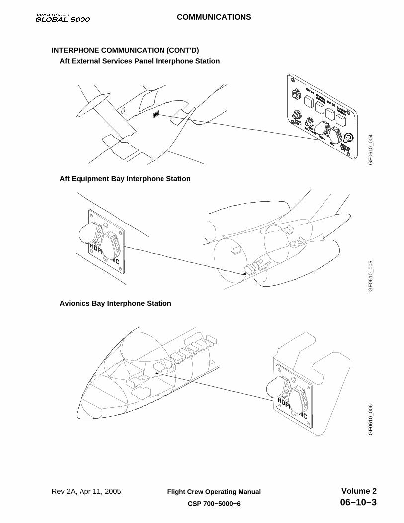
INTERPHONE COMMUNICATION (CONT'D)Aft External Services Panel Interphone Station
GF
0610
_004
Aft Equipment Bay Interphone Station
GF
0610
_005
Avionics Bay Interphone Station
GF
0610
_006
COMMUNICATIONS
Rev 2A, Apr 11, 2005 Flight Crew Operating Manual
CSP 700−5000−6
Volume 206−10−3

INTERPHONE COMMUNICATION (CONT'D)Radio Transmit Switch
Each contol wheel has a toggle switch which activates the selected radio transmitter or theinterphone.
FG
F06
10_0
02
Pilot control wheel is shown, copilot’s opposite.
NOTE
(radio transmitswitch locatedbehind)
AUDIO CONTROL PANEL
The Audio Control Panels (ACPs) operate independently to the remote COMM and NAV units andprovide on-side/cross-side selection. They also control the audio to and from the radios, intercom,PA and aural warning system.
AUDIO CONTROL PANEL INPUT SCHEMATIC
GF
0610
_008
TCAS EGPWS
INTERPHONE AUDIO (flight/service)
AURAL WARNING SYSTEM
PA SYSTEM
MICROPHONE AUDIO (hand, boom and mask mics.)
AUDIO − OPTIONAL SYSTEMS
AUDIO CONTROL PANEL
COMMUNICATIONS
Rev 2A, Apr 11, 2005Flight Crew Operating Manual
CSP 700−5000−6
Volume 206−10−4
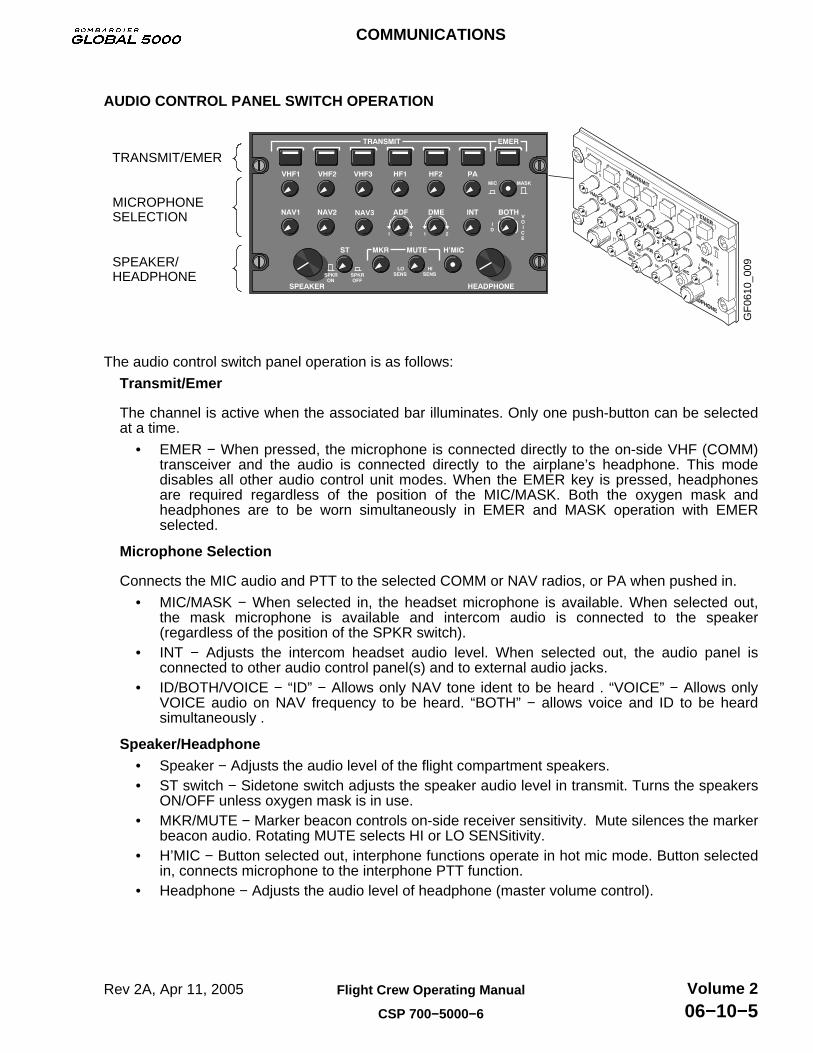
AUDIO CONTROL PANEL SWITCH OPERATION
GF
0610
_009
TRANSMIT/EMER
MICROPHONESELECTION
SPEAKER/HEADPHONE
NAV3
The audio control switch panel operation is as follows:
Transmit/Emer
The channel is active when the associated bar illuminates. Only one push-button can be selectedat a time.
• EMER − When pressed, the microphone is connected directly to the on-side VHF (COMM)transceiver and the audio is connected directly to the airplane’s headphone. This modedisables all other audio control unit modes. When the EMER key is pressed, headphonesare required regardless of the position of the MIC/MASK. Both the oxygen mask andheadphones are to be worn simultaneously in EMER and MASK operation with EMERselected.
Microphone Selection
Connects the MIC audio and PTT to the selected COMM or NAV radios, or PA when pushed in.
• MIC/MASK − When selected in, the headset microphone is available. When selected out,the mask microphone is available and intercom audio is connected to the speaker(regardless of the position of the SPKR switch).
• INT − Adjusts the intercom headset audio level. When selected out, the audio panel isconnected to other audio control panel(s) and to external audio jacks.
• ID/BOTH/VOICE − “ID” − Allows only NAV tone ident to be heard . “VOICE” − Allows onlyVOICE audio on NAV frequency to be heard. “BOTH” − allows voice and ID to be heardsimultaneously .
Speaker/Headphone• Speaker − Adjusts the audio level of the flight compartment speakers.• ST switch − Sidetone switch adjusts the speaker audio level in transmit. Turns the speakers
ON/OFF unless oxygen mask is in use.• MKR/MUTE − Marker beacon controls on-side receiver sensitivity. Mute silences the marker
beacon audio. Rotating MUTE selects HI or LO SENSitivity.• H’MIC − Button selected out, interphone functions operate in hot mic mode. Button selected
in, connects microphone to the interphone PTT function.• Headphone − Adjusts the audio level of headphone (master volume control).
COMMUNICATIONS
Rev 2A, Apr 11, 2005 Flight Crew Operating Manual
CSP 700−5000−6
Volume 206−10−5

RADIO COMMUNICATION SYSTEM
The capability for controlling the operating modes, frequencies and codes can be accomplished byusing the Radio Management Unit (RMU) which is the central control unit for the entire radio system.
The RMU controls all of the VHF COM tuning functions and allows emergency tuning by the FMS.When an FMS tunes the radios, the digital signals from the FMS enter the system where they act inmuch the same manner as if the RMU tuning knob was being operated. This will allow the FMS toenter into the system in an organized manner. For FMS operation, refer to Pilot’s Operating ManualPub No A28-1146-185-00.
The audio section of the VHF COM provides SELCAL outputs used for airplane addressing bytransmitting tones across a VHF COM channel.
VHF 1 and 2 Communications Systems
Two separate, but identical, narrow band width VHF communications systems (VHF 1, VHF 2)which can be operated separately or simultaneously, are provided. These systems are used toprovide AM voice communication between the airplane and a ground station and/or anotherairplane. Frequency tuning and mode selection is by CRT pages and controls on the RMU.
The integrated communications units with transceivers (located in the forward fuselage avionicsbay) provide VHF communication (VHF COM) and Mode S Transponder data link capabilities. Thecommunication transceiver tuning range is as follows:
System Frequency Range Channel Spacing
VHF 1 and 2 118.00 to 151.975 MHz 8.33 kHz
VHF 3 Communications System
The VHF 3 is located in the forward fuselage avionics bay and is used primarily as a data radio. Itdoes not have an ATC transponder but has the capability of operating in the data mode as well asthe voice mode.
The RMU automatically senses when the third VHF COM radio is installed and adds a menuselection to the MENU page. Control of frequency and operating mode is performed by the RMUand FMS CDU. VHF COM 3 works in conjunction with the Data Link System as the data radio. Thecommunication transceiver tuning range is as follows:
System Frequency Range Channel Spacing
VHF 3 118.00 to 151.975 MHz 8.33 kHz
COMMUNICATIONS
Rev 3, Apr 25, 2005Flight Crew Operating Manual
CSP 700−5000−6
Volume 206−10−6
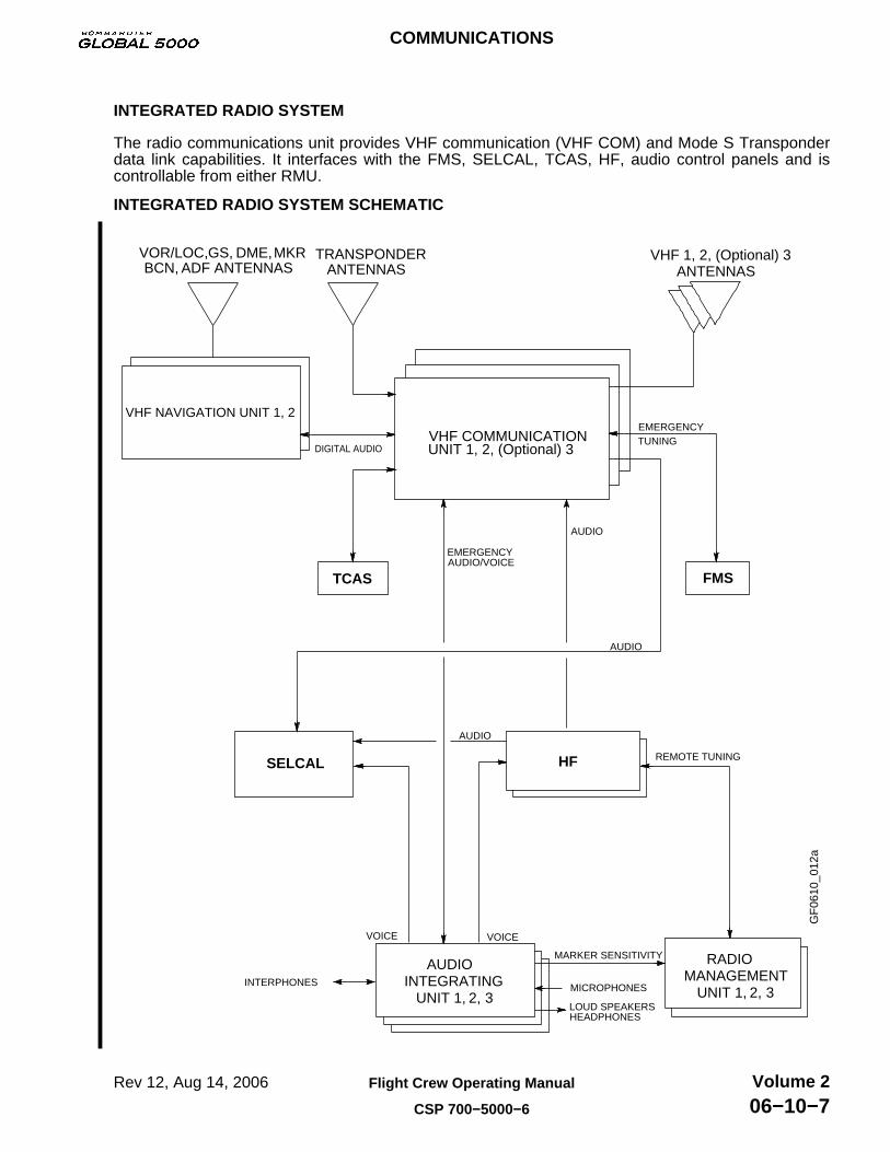
INTEGRATED RADIO SYSTEM
The radio communications unit provides VHF communication (VHF COM) and Mode S Transponderdata link capabilities. It interfaces with the FMS, SELCAL, TCAS, HF, audio control panels and iscontrollable from either RMU.
INTEGRATED RADIO SYSTEM SCHEMATIC
GF
0610
_012
a
VHF NAVIGATION UNIT 1, 2
VHF COMMUNICATION UNIT 1, 2, (Optional) 3
VOR/LOC, GS, DME, MKR BCN, ADF ANTENNAS
TRANSPONDER ANTENNAS
VHF 1, 2, (Optional) 3 ANTENNAS
EMERGENCY TUNING
FMS
AUDIOINTEGRATING
UNIT 1, 2, 3
SELCAL HF
RADIOMANAGEMENT
UNIT 1, 2, 3
TCAS
DIGITAL AUDIO
AUDIO
AUDIO
AUDIO
VOICEVOICE
MICROPHONES
LOUD SPEAKERS HEADPHONES
INTERPHONES
EMERGENCY AUDIO/VOICE
REMOTE TUNING
MARKER SENSITIVITY
COMMUNICATIONS
Rev 12, Aug 14, 2006 Flight Crew Operating Manual
CSP 700−5000−6
Volume 206−10−7

RADIO MANAGEMENT UNIT (RMU) DISPLAY
The following is a description of the panel controls and information available on the RMU.
GF
0610
_013
Transfer Key
Tuning Knobs
Function Keys
Cursor Box
Photo Sensor
Line Select Keys
Main Tuning Page
COM1 NAV1
ATC/TCAS ADF1
TCAS DSPY 1 HF1
NB
MEMORY−1
STANDBY
ALT:
118.00
131.27TEMP−1
131.10
112.00
1605ANT
620.0
REL
NORMAL 2000
2000LV
GF
0610
_014
RMU 1 (Pilot’s) RMU 2 (Copilot’s)
118.02MEMORY−4
ALT:
MEMORY−1110.00
NB
REL
NORMAL
STANDBY ADF
LV
TCAS DSPY 2
ADF2ATC/TCAS
HF2
COM2 NAV2
121.82 117.45
1200 1799.5
15423
15600
NB
REL
NORMAL
STANDBY ADF
LV
118.02MEMORY−4
ALT:
MEMORY−1110.00
ADF1ATC/TCAS
HF1TCAS DSPY 1
COM1 NAV1
121.82 117.45
1200 1799.5
15423
15600
PILOT’SWINDOWContains thefollowing:
COM 1
NAV 1
ATC/TCAS
ADF 1
TCAS DSPY 1
HF 1
COPILOT’SWINDOWContains thefollowing:
COM 2
NAV 2
ATC/TCAS
ADF 2
TCAS DSPY 2
HF 2
COMMUNICATIONS
Rev 2A, Apr 11, 2005Flight Crew Operating Manual
CSP 700−5000−6
Volume 206−10−8

RADIO MANAGEMENT SYSTEM
The RMU is mounted in the centre pedestal. It is a colour Liquid Crystal Display (LCD) based radiotuning controller that provides centralized control and display of frequencies, channels, codes andmodes set on the communications and navigation receivers. Each RMU provides single point controlof both the on-side and cross-side radios. The RMUs provide on-side and cross-side access to thefollowing radios:
RMU − 1 RMU − 2
VHF COM − 1 VHF COM − 2
VHF NAV − 1 VHF NAV − 2
DME − 1 DME − 2
ADF − 1 ADF − 2
ATC − 1 ATC − 2
TCAS DSPY 1 TCAS DSPY 2
HF − 1 HF − 2
The RMU uses the concept of selecting a function by pushing a line select key next to the parameterthat you wish to control. Any selectable parameter may be changed by pressing the correspondingline key next to the displayed parameter and then rotating the concentric tuning knobs to set thedesired value.
The RMU display is divided into dedicated windows. Each window groups the data associated with aparticular function of the radio system. The windows COM, NAV, ATC, HF, ADF and TCAS eachprovide for complete control of frequency and operating mode of the associated function.
The RMU also has other display modes, called pages, which perform additional features andfunctions for the control of the radio system. A menu of the pages is provided to access theseadditional functions.
Located on the front of the RMU is a button labeled PGE, which when pressed, causes the systempage menu to be displayed. Pressing PGE will allow the selection of other functions such as:
• Radio page: Normal tuning.
• COMM memory: Preset COMM frequencies.
• NAV memory: Preset VOR NAV frequencies.
• ATC/TCAS: ATC/TCAS display parameters.
• HF control: Preset and Direct tune modes.
• Maintenance: Access to maintenance data only on ground.
COMMUNICATIONS
Rev 2A, Apr 11, 2005 Flight Crew Operating Manual
CSP 700−5000−6
Volume 206−10−9

RADIO MANAGEMENT SYSTEM (CONT'D)General Colour Philosophy
GF
0610
_016
NB
REL
NORMAL
STANDBY ADF
LV
118.02MEMORY−4
ALT:
MEMORY−1110.00
ADF1ATC/TCAS
HF1TCAS DSPY 1
COM1 NAV1
121.82 117.45
1200 1799.5
15423
15600
For radio parameters the RMU provides a local tune colour and a remote tune colour. Local tune isperformed on same RMU it is observed on. Remote tune is performed on another tuning source:the other RMU or the FMS. Following local tune, the tuned item changes to the local tuned colour.
Item Local Tune Colour Example
VHF 1 and 2 White NAV Display Channel
Preset Data Cyan COM Preset Channel
Mode Data Green ADF Mode
FMS Data Magenta Nav Auto Annunciator
Following remote tune, the tuned item changes to yellow, with one exception − an FMS databasetune (auto tune) of the NAV display channel, which is magenta.
Item Remote Tune Colour Example
Channel Data Yellow NAV Display Channel
Preset Data Yellow COM Preset Channel
Mode Data Yellow ADF Mode
FMS Data Base Magenta Nav AUTO Annunciator
COMMUNICATIONS
Rev 2A, Apr 11, 2005Flight Crew Operating Manual
CSP 700−5000−6
Volume 206−10−10

RADIO MANAGEMENT SYSTEM (CONT'D)General Colour Philosophy (Cont’d)
Other items which are not radio parameters, such as page banners and window labels, also followa general colour philosophy. The page banners and window labels are white when the on-side isselected and are magenta when the off-side system is selected. Example: on RMU #1 the HFwindow label is white when HF 1 is selected and magenta when HF 2 is selected.
Item Fixed Tune Colour Example
Field Labels Cyan TCAS INTRUDER ALTITUDE
Key Labels Cyan Page Menu HF CONTROL Key
Caution/Notice Yellow Transponder ATC ERR
Transfer Keys
The transfer key when pushed, flip-flops the active (top line) frequency and the preset (bottom line)frequency of the respective VHF COM, VHF NAV or HF COM window. Example below:
GF
0610
_020
TEMP−1113.10
ATC/TCAS ADF1
130.27TEMP−1
118.00 112.00COM1 NAV1NB
ATC/TCAS ADF1
118.00TEMP−1 TEMP−1
113.10112.00130.27
COM1 NAV1NB
Line Select Keys
The first push of the line select key moves the yellow cursor to surround the data field associatedwith that particular line select key. It also electronically connects that data field to the tuning knobsso that the frequency or mode may be changed. For some functions, additional pushes of the lineselect key will toggle modes or recall stored frequencies. The line select key, when pressed andheld for certain functions, allows the ADF and ATC memories to be recalled and to enter and exitdirect tune mode for the VHF COM and the VHF NAV.
GF
0610
_021
130.27TEMP−1 TEMP−1
113.10
COM1 NAV1
118.00 112.00
ATC/TCAS ADF1
NB
ADF1
130.27TEMP−1 TEMP−1
113.10
COM1 NAV1
118.00 112.00
ATC/TCAS
1200 1799.5
NB
1 ATC ALT ADF
Function Keys and Tuning Knobs
Function keys provide control of system data/configuration. The tuning knobs are used to modifythe data field inclosed by the cursor. This may be frequency or mode depending on the data field.
GF
0610
_022TUNE CONTROL KNOBS
FUNCTION KEYS
COMMUNICATIONS
Rev 2A, Apr 11, 2005 Flight Crew Operating Manual
CSP 700−5000−6
Volume 206−10−11
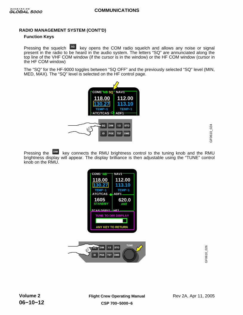
RADIO MANAGEMENT SYSTEM (CONT'D)Function Keys
Pressing the squelch key opens the COM radio squelch and allows any noise or signalpresent in the radio to be heard in the audio system. The letters “SQ” are annunciated along thetop line of the VHF COM window (if the cursor is in the window) or the HF COM window (cursor inthe HF COM window)
The “SQ” for the HF-9000 toggles between “SQ OFF” and the previously selected “SQ” level (MIN,MED, MAX). The “SQ” level is selected on the HF control page.
GF
0610
_024
130.27TEMP−1 TEMP−1
113.10
SQNB NAV1
ATC/TCAS ADF1
COM1
118.00 112.00
Pressing the key connects the RMU brightness control to the tuning knob and the RMUbrightness display will appear. The display brilliance is then adjustable using the “TUNE” controlknob on the RMU.
GF
0610
_026
TCAS DSPY1 HF1
130.27TEMP−1 TEMP−1
113.10
COM1 NAV1
118.00 112.00
1605 620.0ATC/TCAS ADF1
STANDBY ANT
NB
ANY KEY TO RETURN
TUNE TO DIM DISPLAY
COMMUNICATIONS
Rev 2A, Apr 11, 2005Flight Crew Operating Manual
CSP 700−5000−6
Volume 206−10−12

RADIO MANAGEMENT SYSTEM (CONT'D)Function Keys (Cont’d)
Pressing the cross-side key, with the cursor in a window (except ATC /TCAS) displaytransfers the entire RMU operation and display to the cross−side radio system. The legend colourchanges from white to magenta when the RMU is displaying and is in control of, data associatedwith the cross−side system. Pressing the 1/2 key with the cursor on the mode line of theATC−TCAS window and the transponder in other than STANDBY mode allows to switch betweentransponder 1 and 2.
GF
0610
_028
COMMUNICATIONS
Rev 2A, Apr 11, 2005 Flight Crew Operating Manual
CSP 700−5000−6
Volume 206−10−13
RADIO MANAGEMENT SYSTEM (CONT'D)Function Keys (Cont’d)
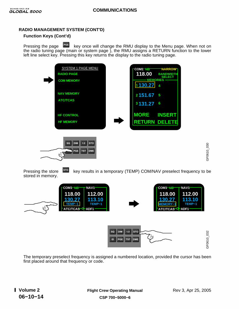
Pressing the page key once will change the RMU display to the Menu page. When not onthe radio tuning page (main or system page ), the RMU assigns a RETURN function to the lowerleft line select key. Pressing this key returns the display to the radio tuning page.
GF
0610
_030
COM1
118.00
130.27
151.67
131.27
2
3
1 4
5
6
INSERTDELETE
MORERETURN
MEMORIES
NB NARROW
BANDWIDTHSELECT
RADIO PAGE
COM MEMORY
NAV MEMORY
ATC/TCAS
HF CONTROL
HF MEMORY
SYSTEM 1 PAGE MENU
Pressing the store key results in a temporary (TEMP) COM/NAV preselect frequency to bestored in memory.
GF
0610
_032
130.27TEMP−1 TEMP−1
113.10
ATC/TCAS ADF1
COM1 NAV1
118.00 112.00NB
130.27MEMORY−1 TEMP−1
113.10
ATC/TCAS ADF1
COM1 NAV1
118.00 112.00NB
The temporary preselect frequency is assigned a numbered location, provided the cursor has beenfirst placed around that frequency or code.
COMMUNICATIONS
Rev 3, Apr 25, 2005Flight Crew Operating Manual
CSP 700−5000−6
Volume 206−10−14

RADIO MANAGEMENT SYSTEM (CONT'D)Function Keys (Cont’d)
While on the main tuning page, press the function key once to display the SYSTEM 1PAGE MENU. Next press the line select key for the COM MEMORY to view the frequency held inmemory.
GF
0610
_033
COM1
118.00
130.27
2
3
1 4
5
6
INSERTDELETE
MORERETURN
MEMORIES
NB NARROW
BANDWIDTHSELECTStep 1
Step 2 SYSTEM 1 PAGE MENU
RADIO PAGE
COM MEMORY130.27MEMORY−1 TEMP−1
113.10
ATC/TCAS ADF1
COM1 NAV1
118.00 112.00NB
Pressing the identification key places the transponder in the identification response mode.The transponder will go into ident mode for approximately 18 seconds when the ID function key ispushed and an ID annunciator will appear.
GF
0610
_035
IdentificationAnnunciator
118.02MEMORY−4
NB
1 ATC ALT ADF
ADF1ATC/TCAS ID
COM1 NAV1
121.82 108.30
1799.5
DME IUL
109.30
1200
COMMUNICATIONS
Rev 3, Apr 25, 2005 Flight Crew Operating Manual
CSP 700−5000−6
Volume 206−10−15

RADIO MANAGEMENT SYSTEM (CONT'D)Function Keys (Cont’d)
A self test sequence of any radio is available. Press/hold the key with the cursor placedaround the frequency or code to activate an internal test sequence of the selected system.
GF
0610
_037
ADF ERR
TESTADF−TEST
TEST
TEST
TEST
HF1
ADF1
HF1
ADF1
HF1
ADF1ATC/TCAS
TCAS DSPY 1
COM1 NAV1
118.00 131.10
1605
2000
ADF1
HF1
131.27MEMORY−1 TEMP−1
112.00
2000ADF PASS
NB
STANDBY
UVALT: RELNORMAL
NOTE
Not all of the test events which can be displayed are shown. Only the ADF Pass/Error example is represented.
OR
ADF1
HF1
NB
ATC/TCAS
TCAS DSPY 1
COM1 NAV1
118.00 131.10
1605 620.0
2000
131.27MEMORY−1 TEMP−1
112.00
2000
STANDBY ANT
UVALT: RELNORMAL
The key must be held down for the duration of the test for approximately:
• 2 seconds for VHF COM and HF COM.• 5 to 7 seconds for DME, ATC, ADF.• 20 seconds for NAV (VOR/ILS).• The TCAS test function is as follows.
After the test is complete, a PASS or ERR (error) legend will appear in the window.
NOTE
If the key is held for 30 seconds or more, the radios areautomatically commanded back into normal operation.
Releasing the key at any time, immediately returns the function to normal operation.
COMMUNICATIONS
Rev 3, Apr 25, 2005Flight Crew Operating Manual
CSP 700−5000−6
Volume 206−10−16

RADIO MANAGEMENT SYSTEM (CONT'D)Function Keys (Cont’d)
Pressing the key “de-slaves” the DME from the active VOR frequency, so a different DMEchannel may be tuned, without changing the active VOR. Successive presses of the “DME” keyenables display and selection of the DME channels in VHF and TACAN formats.
GF
0610
_039
NOTECycling the DME function button will display the following in sequence:VOR/ILS − VOR/ILS and DME − VOR/ILS and TACAN − VOR/ILS
118.02MEMORY−4
RANGE:
H IZZDME
NB
6NORMAL
1 ATC ALT ADF
LV
1799.5
111.90
121.82 108.30
ADF1ATC/TCAS
HF1
COM1 NAV1
1200
15423
15600
ILS/VOR DME Ident
TCAS DSPY 1
COMMUNICATIONS
Rev 2A, Apr 11, 2005 Flight Crew Operating Manual
CSP 700−5000−6
Volume 206−10−17
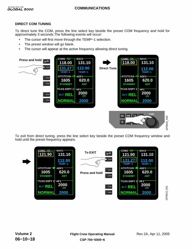
DIRECT COM TUNING
To direct tune the COM, press the line select key beside the preset COM frequency and hold forapproximately 3 seconds.The following events will occur:
• The cursor will first move through the TEMP−1 selection.• The preset window will go blank.• The cursor will appear at the active frequency allowing direct tuning.
GF
0610
_040
HF1
NB
131.27TEMP−1 TEMP−1
112.00
2000
TEMP−1112.00
2000
NB
STANDBY ANT
UV
STANDBY ANT
UVALT: RELNORMAL
ALT: RELNORMAL
620.0ADF1
NAV1
131.10
620.0
2000
ATC/TCAS
COM1
118.00
1605ADF1
HF1
131.10
2000
NAV1
1605ATC/TCAS
118.00COM1Press and hold
Direct Tune
TUNE
TCAS DSPY 1 TCAS DSPY 1
To exit from direct tuning, press the line select key beside the preset COM frequency window andhold until the preset frequency appears.
GF
0610
_041
131.27TEMP−1 TEMP−1
112.00
2000
HF1
NB
STANDBY ANT
UVALT: RELNORMAL
ADF1ATC/TCAS
TCAS DSPY 1
COM1 NAV1
121.90 131.10
1605 620.0
2000
To EXIT
Press and hold
HF1
NB
TEMP−1112.00
2000
STANDBY ANT
UVALT: RELNORMAL
ADF1
NAV1
131.10
620.0
2000
ATC/TCAS
TCAS DSPY 1
COM1
121.90
1605
COMMUNICATIONS
Rev 2A, Apr 11, 2005Flight Crew Operating Manual
CSP 700−5000−6
Volume 206−10−18
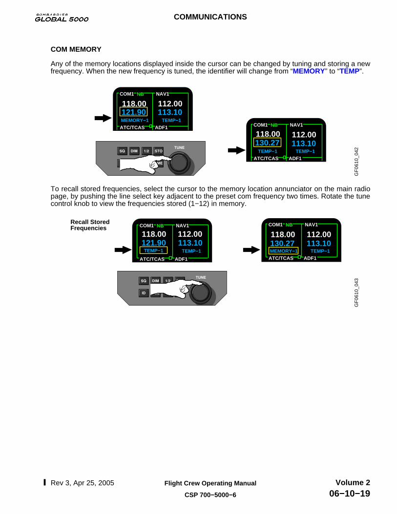
COM MEMORY
Any of the memory locations displayed inside the cursor can be changed by tuning and storing a newfrequency. When the new frequency is tuned, the identifier will change from “MEMORY” to “TEMP”.
GF
0610
_042
121.90MEMORY−1 TEMP−1
113.10
NBCOM1
118.00 112.00
ATC/TCAS ADF1
NAV1
TEMP−1
130.27TEMP−1
113.10
NBCOM1 NAV1
118.00 112.00
ATC/TCAS ADF1
To recall stored frequencies, select the cursor to the memory location annunciator on the main radiopage, by pushing the line select key adjacent to the preset com frequency two times. Rotate the tunecontrol knob to view the frequencies stored (1−12) in memory.
GF
0610
_043
Recall Stored Frequencies
MEMORY−1130.27
TEMP−1113.10121.90
TEMP−1 TEMP−1113.10
NB NBCOM1
118.00 112.00
ATC/TCAS ADF1
NAV1 COM1 NAV1
118.00 112.00
ATC/TCAS ADF1
COMMUNICATIONS
Rev 3, Apr 25, 2005 Flight Crew Operating Manual
CSP 700−5000−6
Volume 206−10−19
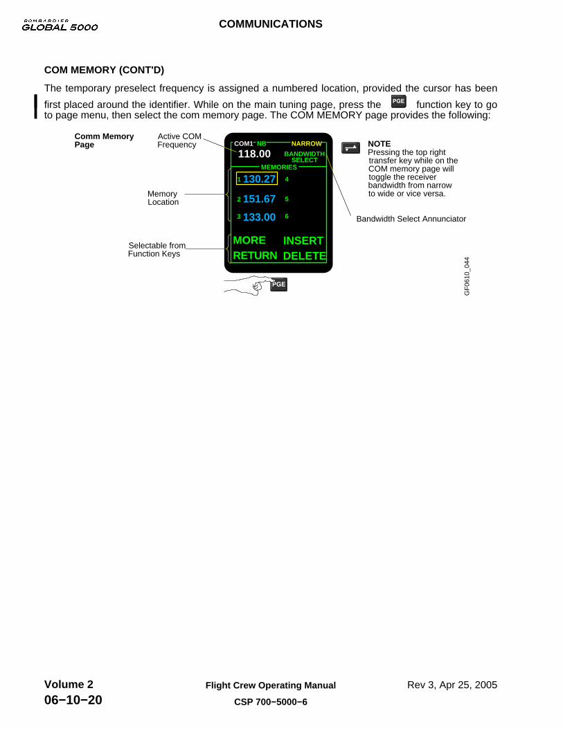
COM MEMORY (CONT'D)
The temporary preselect frequency is assigned a numbered location, provided the cursor has been
first placed around the identifier. While on the main tuning page, press the function key to goto page menu, then select the com memory page. The COM MEMORY page provides the following:
GF
0610
_044
COM1
118.00
130.27
151.67
133.00
2
3
1 4
5
6
INSERTDELETE
MORERETURN
MEMORIES
NB NARROW
BANDWIDTHSELECT
Active COM Frequency
Bandwidth Select Annunciator
Memory Location
Selectable from Function Keys
Pressing the top right transfer key while on the COM memory page will toggle the receiver bandwidth from narrow to wide or vice versa.
Comm Memory Page NOTE
COMMUNICATIONS
Rev 3, Apr 25, 2005Flight Crew Operating Manual
CSP 700−5000−6
Volume 206−10−20

HIGH FREQUENCY (HF) COMMUNICATION SYSTEM
The HF communication system is a dual configuration integrated with the radio system on theairplane. The system provides long range air-to-air and air-to-ground communications, operates inthe 2.0000 to 29.9999 Mhz range and consists of:
• Two transceivers/antenna couplers.• One antenna.
The basic radio control functions are:
• HF COM mode and frequency.• Audio selection and volume control.
Frequency and mode control of the remotely located HF radios can be input from either the RMUs orthe Flight Management System (FMS) CDUs. Both normal Simplex Tuning mode and EmergencyTuning mode are supported by the FMS. The audio control panels provides microphone selection,radio headset/speaker audio selection, volume control and audio control switching.
The HF transceiver units (HF COM 1 and HF COM 2) are located in the Aft Avionics Bay. The HFantenna coupler units are located in the upper Aft Fuselage. The antenna is located in the VerticalStabilizer (forms the leading edge).
The RMUs are the central control for the HF Communication System, providing complete capabilityfor controlling the operational mode and frequencies. Each RMU has the capability to controloperation of its primary (on-side) radio or its secondary (cross-side) radio.
The HF information on each RMU is displayed at the lower right of the radio tuning page. HFemission mode and status are displayed in the HF window. In order to tune a frequency on HF, oneof the two line select keys on the lower right side of the RMU is pressed. This selection will place the“cursor tune box” around the frequency to be tuned and using the RMU tuning knobs will accomplishthe desired frequency. The HF System can operate in the following modes: Upper Sideband Voice(UV), Lower Sideband Voice (LV), Amplitude Modulation Equivalent (AM) and Continuous Wave(CW).
RMU HF DISPLAY
GF
0610
_045
ADF1ATC/TCAS
HF1
COM1 NB NAV1
118.00 131.10
131.27MEMORY−1 TEMP−1
1605 620.0
2000
STANDBY ANT
UV
112.00
HF Line Select Keys
Cursor Box
2000ALT: RELNORMAL
TCAS DSPY 1
COMMUNICATIONS
Rev 3, Apr 25, 2005 Flight Crew Operating Manual
CSP 700−5000−6
Volume 206−10−21

RMU HF DISPLAY (CONT'D)
The RMU HF window is optimized for use with Upper Sideband voice mode. The HF window has twomodes of operation: Preset Tune mode and Direct Tune mode. Both the active and preset aredisplayed when the RMU is in preset tune mode, while only the active frequency is displayed in directtune mode.
The HF will keep the most recently keyed HF tuned to the antenna for 20 seconds after thepush-to-talk key opens. Following 20 seconds the HF reverts to “Dual Receive mode” (neither HFantenna remains tuned to the antenna) providing the squelch is not open.
HF Preset and Direct Tuning Modes
GF
0610
_046
HF 1 Active Mode
HF1
28000UV
26460
HF128000
UV
HF 1 Preset Mode
When the coupler is tuning to match the antenna, a steady tone will be heard from the transceiver.If tuning takes longer than six seconds, the tone will begin to beep, signaling that the coupler wasnot able to tune properly. If this occurs, an “ERR” annunciator is displayed and the frequency datawill dash (− − − − −) on the RMU HF window. To clear this fault, tune any HF parameter on theRMU. For information on additional message annunciations, refer to the manufacturer pilothandbook on HF communication.
HF Fault Annunciation
GF
0610
_047
HF1
26460
ERR
HF communication control and status are accessed and/or displayed on “back” pages of the RMU.These pages are accessed via RMU “PAGE MENU” page:
• HF Control Page.• HF Memory Page.• Maintenance Log.
COMMUNICATIONS
Rev 3, Apr 25, 2005Flight Crew Operating Manual
CSP 700−5000−6
Volume 206−10−22

RMU HF DISPLAY (CONT'D)Menu Page
The menu page is accessed from the radio tuning page by pressing the “PAGE” function key onthe front face of the RMU. All stored frequencies are displayed and there are six memory locationson the first page and an additional six available on the second page.
The HF Maintenance Log provides the maintenance log for on-side HF radio operation. TheMaintenance page is a ground maintenance function and will not be covered in this manual.
GF
0610
_048
SYSTEM 1 PAGE MENU
COM MEMORY
NAV MEMORY
HF CONTROL
HF MEMORY
ATC/TCAS
RETURN TO
SYS SELECT
MAINTENANCERADIOS
COMMUNICATIONS
Rev 3, Apr 25, 2005 Flight Crew Operating Manual
CSP 700−5000−6
Volume 206−10−23

RMU HF DISPLAY (CONT'D)HF Memory and Control Pages
The HF Control page provides active and preset channel tuning, emission mode control, memorychannel recall/store, HF status, squelch level tuning and transmitter power level tuning.
The HF Memory page provides active channel tuning, memory channel tuning and HF status.
GF
0610
_049
HF 1 MEMORY Page HF 1 CONTROL Page
HF 1 MEMORY
12260
MODE:
ACTIVE
LOAD
29000
MORE
RETURN TORADIOS
UV
MEMORY−10
UV
29209MEMORY−11
UV
29200MEMORY−12
UV
SIMPL
HF 1 CONTROL
12260
MODE
ACTIVE
TRANSFER
29000
RETURN TORADIOS
UV
PRESET
UV
TEMP− 1
:SIMPL ACT
LEVELSQUELCH:MAX POWER
TX :MAX
MODE :SIMPL PRE
COMMUNICATIONS
Rev 3, Apr 25, 2005Flight Crew Operating Manual
CSP 700−5000−6
Volume 206−10−24
SELCAL
The Selective Calling System (SELCAL) monitors the ground stations for a four letter tone code thatis transmitted to the airplane on the VHF or HF communication systems. When the SELCAL receivesthe code, it sends a visual and aural message to alert the flight crew.
The SELCAL decoder unit located in the forward avionics equipment bay, has five audio inputchannels used to monitor the audio output from:
• VHF COM 1.• VHF COM 2.• VHF COM 3.• HF COM 1.• HF COM 2.
The SELCAL interfaces with the audio integrating system (audio control panels), flight compartmentspeakers and EICAS. Each airplane is assigned its own SELCAL code at the time of installation.Upon receiving the code for which it was programmed, the SELCAL will signal the audio integratingand EICAS systems that a call has been received.
Operation
The VHF and/or HF communication systems are tuned to a SELCAL frequency that has beenassigned to a ground station.
When a ground station wants to talk to the flight crew, the ground station sends a SELCAL codeon the assigned frequency. The SELCAL unit monitors the VHF and HF communication systemsaudio output channels.
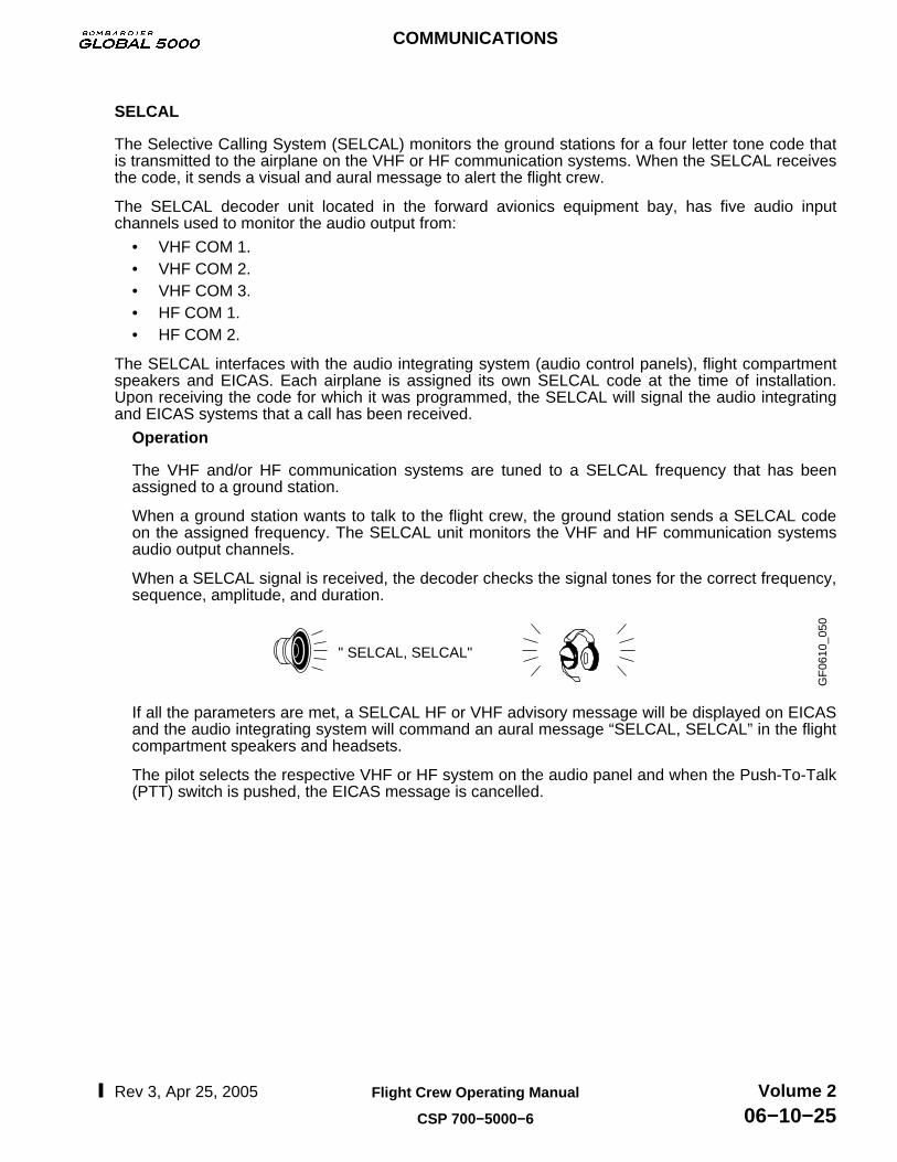
When a SELCAL signal is received, the decoder checks the signal tones for the correct frequency,sequence, amplitude, and duration.
GF
0610
_050
" SELCAL, SELCAL"
If all the parameters are met, a SELCAL HF or VHF advisory message will be displayed on EICASand the audio integrating system will command an aural message “SELCAL, SELCAL” in the flightcompartment speakers and headsets.
The pilot selects the respective VHF or HF system on the audio panel and when the Push-To-Talk(PTT) switch is pushed, the EICAS message is cancelled.
COMMUNICATIONS
Rev 3, Apr 25, 2005 Flight Crew Operating Manual
CSP 700−5000−6
Volume 206−10−25

RADIO ALTIMETER
The Radio Altimeter (RA) system provides airplane altitude above the terrain up to +2550 feet. TheRA system is comprised of two RA transceivers, each connected to two separate antennas. Theantennas are identical and dedicated, one for transmitting and the other for receiving. The antennasare positioned on the bottom centerline of the fuselage to minimize performance degradation in turnsand prior to landing while in the flare on landing.
GF
0610
_051
RAD
Radio Altitude Failure
Boxed "RAD" display replaces RA digits.
Takes priority over miscompare annunciation.
Radio Altitude Miscompare
Boxed "RAD" display above RA digits.
Indicates a miscompare of greater than 10 feet on ground and varies with altitude in flight.
0RAD
2020
2020
The altitude above the terrain indication for approach and landing phases of operation is displayedon the Primary Flight Display (PFD).
GF
0610
_052
MINIMUMS Outer Knob
Height (DH) value on PFD.RAD − Sets the Decision
AP1 104 00HDGVAPP
500 RAD
ASELVNAV
RAD BAROMINIMUMS
The Decision Height (DH) is displayed on the PFD when the minimums on the PFD controller is setto RAD.
The following systems receive RA information:
• TCAS.• EGPWS.• FCUs.• DAUs (to display processors for PFD displays).
Refer to FLIGHT INSTRUMENTS Chapter 11, for additional information on RA indications.
COMMUNICATIONS
Rev 3, Apr 25, 2005Flight Crew Operating Manual
CSP 700−5000−6
Volume 206−10−26

STATIC DISCHARGER
The airplane wings and tail sections contain static wicks installed to discharge static electricity,reducing radio interference. They are installed at the following locations:
• Winglets/wingtips and ailerons.• Elevators, rudder, vertical stabilizer, horizontal stabilizer and tail cone.
GF
0610
_053
There are two parts to each static discharge assembly: the static discharger and the mounting base.If any are found missing during the walkaround, refer to the configuration deviation list of the AFM toverify if you can dispatch.
GF
0610
_054
COMMUNICATIONS
Rev 3, Apr 25, 2005 Flight Crew Operating Manual
CSP 700−5000−6
Volume 206−10−27

COCKPIT VOICE RECORDER
The Cockpit Voice Recorder (CVR) is a crash survivable recording device that simultaneouslyrecords four channels of audio data representing the cockpit acoustic environment. The systemconsists of:
• CVR.• Microphone monitor/control panel.• Remote area microphone.• Impact switch.
CVR LOCATION
The CVR retains the most recent two hours of recorded information in memory. Input is receivedfrom each audio control panel and CVR area microphone. The CVR also receives digital data (GMTtime) from DAU 4 to synchronize the CVR with the flight data recorder.
COCKPIT VOICE RECORDER
GF
0610
_055
The CVR is mounted in the aft equipment bay. The microphone monitor/control panel is located inthe flight compartment right side panel.
MICROPHONE MONITOR CONTROL PANEL
GF
0610
_056
STATUS Display Illuminates as a function of test and/or failure.
ERASE Push button Pushing the ERASE push button initiates a memory erase sequence within the CVR.
HEADSET Monitor Jack Used to monitor tone transmissions during test and audio signals currently being recorded.
TEST Push button Pushing the test button will activate the CVR internal self-test.
COCKPIT VOICE RECORDER MICROPHONE MONITOR
TESTERASE
STATUS HEADPHONE
COMMUNICATIONS
Rev 3, Apr 25, 2005Flight Crew Operating Manual
CSP 700−5000−6
Volume 206−10−28

REMOTE AREA MICROPHONE
An area microphone is mounted in the flight compartment overhead panel.
GF
0610
_057
AREA MICROPHONE
IMPACT SWITCH
The impact switch mounted in the aft avionics bay removes electrical power to the CVR when theairplane experiences an impact.
GF
0610
_058
AFT AV BAY
IMPACT SWITCH
Audio Control Panel Input
The audio panels provide audio inputs to the CVR for recording flight crew voice communicationsand other flight compartment audio signals.
GF
0610
_059
Audio Control Panel
The various audio signals are summed together in the audio panels to form a single audio input tothe CVR from each audio panel.
COMMUNICATIONS
Rev 3, Apr 25, 2005 Flight Crew Operating Manual
CSP 700−5000−6
Volume 206−10−29
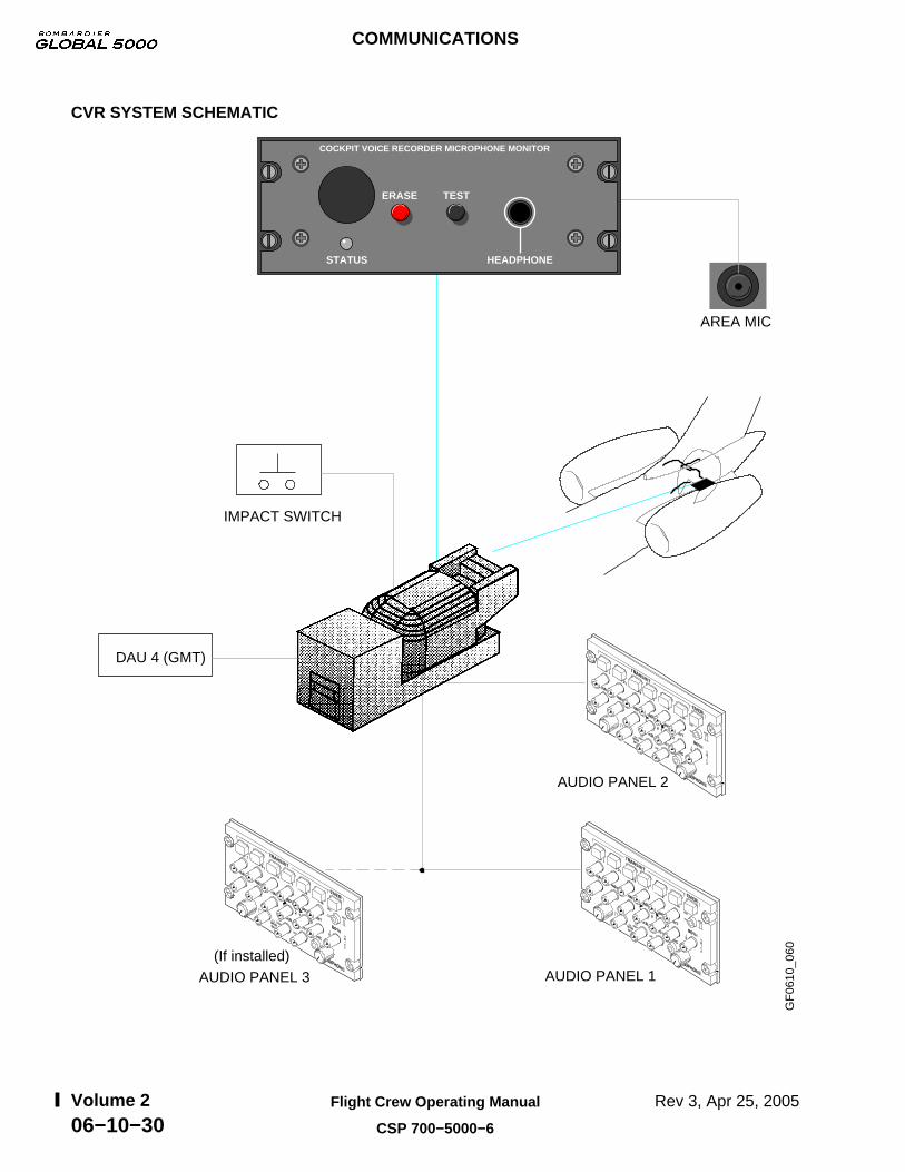
CVR SYSTEM SCHEMATIC
DAU 4 (GMT)
AUDIO PANEL 3
(If installed)
AUDIO PANEL 2
AUDIO PANEL 1
IMPACT SWITCH
AREA MIC
GF
0610
_060
COCKPIT VOICE RECORDER MICROPHONE MONITOR
TESTERASE
STATUS HEADPHONE
COMMUNICATIONS
Rev 3, Apr 25, 2005Flight Crew Operating Manual
CSP 700−5000−6
Volume 206−10−30

MICROPHONE MONITOR CONTROL PANEL TEST
The cockpit voice recorder microphone monitor panel “TEST”, “STATUS” and “ERASE” functions areas follows:
• TEST − Push and hold the “TEST” push-button for approximately one second to activate theCVR internal self-test.
GF
0610
_061
PASSENGER OXYGEN
CLOSED OVERRIDE
NORMAL
FIRST AID
TEST PORT
PASS ONOFF
A successful test will result in the green “STATUS” LED illuminating for one second and a twosecond aural tone will be heard using the headphone.
NOTE
If a failure occurs during the self test, the green “STATUS” LED willilluminate continuously and no aural tone will be heard.
"TONE"G
F06
10_0
62
• STATUS − The operation of the green “STATUS” LED is described above under the “TEST”function.
• ERASE − The “ERASE” push-button is used to initiate a memory erase sequence within theCVR. The CVR logic ensures that the “ERASE” function is only enabled when the airplane ison the ground (WOW) and the parking brake set.
COMMUNICATIONS
Rev 3, Apr 25, 2005 Flight Crew Operating Manual
CSP 700−5000−6
Volume 206−10−31

FLIGHT DATA RECORDER
The Flight Data Recorder (FDR) is a crash survivable data recorder capable of retaining up to25 hours of airplane parameters/flight data. The FDR system consists of:
• Solid state flight data recorder.• High-G accelerometer.
The High-G accelerometer is mounted in the airplane landing gear bay and provides the normalacceleration data for the FDR system.
The DAU 4 receives airplane parameters/flight data from various systems and normal accelerationinput from a dedicated accelerometer. The FDR receives its systems information from DAU 4 andsends status information back to the DAU 4. A FDR self-test is performed on airplane power-up andif a failure is detected at any time (including self-test), an advisory message will be displayed onEICAS.
G−ACCELEROMETER
STATUSDAU 4
INPUTSDATA INPUT
FDR
GF
0610
_063
QUICK ACCESS RECORDER (IF INSTALLED)
The optional Quick Access Recorder (QAR) is an independent flight data recording devise thatrecords the same data as the FDR. The QAR can retain up to 750 hours of airplane parameters/flightdata. If a QAR failure occurs, the FDR FAIL message will be displayed on EICAS.
COMMUNICATIONS
Rev 12, Aug 14, 2006Flight Crew Operating Manual
CSP 700−5000−6
Volume 206−10−32

UNDERWATER LOCATOR BEACON
An Underwater Locator Beacon (ULB) is attached to the CVR as part of the handle to help locate it inthe event of a crash.
GF
0610
_064
UNDERWATER LOCATOR BEACON
The ULBs operating frequency is 37.5 KHz and will operate for 30 days.
EMERGENCY LOCATOR TRANSMITTER
The Emergency Locator Transmitter (ELT) consists of:
• ELT switch.• Emergency locator transmitter.• ELT antenna.
A flight compartment switch located on the overhead panel provides “ON” and “ARM” modes ofoperation. The switch can be used to manually activate the ELT for test purposes or emergencysituations.
LIGHT SENSOR - ELT PANEL
FG
F06
10_0
03LIGHT SENSOR − ELT PANEL
ON − When selected the ELT willbegin to transmit.
− Normal position selected to arm the systemfor automatic activation.
ELT Switch
ARM/RESET
If the system is accidentally activated, the unitcan be reset by placing the switch to ON, then back to ARM/RESET.
NOTE
ELT
FOR AVIATIONEMER USE ONLY
UNAUTHORIZED OPERATION PROHIBITED
ON
ARM/RESET
COMMUNICATIONS
Rev 12, Aug 14, 2006 Flight Crew Operating Manual
CSP 700−5000−6
Volume 206−10−33

LIGHT SENSOR - ELT PANEL (CONT'D)
The ELT transmits signals on 121.5, 243.0 and optional 406.025 MHz. The 406.025 MHz may beinstalled as part of the ELT and its signal is transmitted for satellite relay. Upon activation, the 121.5,243.0 signals operate continuously until the self contained battery pack power is exhausted (typicallylast at least 72 hours) or the unit is reset. If the optional 406 MHz transmitter module is installed, theoutput signal is transmitted for 24 hours (once every 47 seconds) then automatically shuts off. The121.5, 243.0 signals are shut off while the 406 MHz signal is transmitting.
ELT SCHEMATIC
GF
0610
_066
EMERGENCY LOCATOR TRANSMITTER
DAU 2 IACEICAS DISPLAY
EICASADVISORYMESSAGE
ON
ARM
121.5/243.0 MHz406.025 MHz
ELT TRANSMITTING
ELT ANTENNA
ELT
FOR AVIATIONEMER USE ONLY
ON
ARM/RESET
An internally mounted “G” switch is triggered on impact and activates the ELT. The ELT antenna ismounted on the top aft exterior of the airplane and interfaces with all signal outputs. When the ELT istransmitting, a signal is sent to the transmitter to DAU 2. This signal used by the DAU provides anELT transmitting advisory message to EICAS.
COMMUNICATIONS
Rev 12, Aug 14, 2006Flight Crew Operating Manual
CSP 700−5000−6
Volume 206−10−34

AIRBORNE DATA LINK SYSTEM
Airborne Data Link System (ADLS) operation is via the third VHF comm, UHF (telephony) orSATCOM and controllable from all FMS CDUs. The system utilizes the same data loading unit as theFMS with printer interface, air−ground−air and air−to−air capabilities. Crew advisory messages aredisplayed on the CDU scratch pad.
Communication Links
Third VHF COMM − Using the SYSTEM SELECT page on the RMU, the pilot can select COM 3MODE to be VOICE or DATA. When DATA is selected, the data link is in control of the radio; datafrequency is selectable only through the data link.
SATCOM − Automated to this link as required (VHF or UHF not available). Pilot selectable ifdesired.
UHF (Telephony) − Available through the Cabin Communication System. Weather maps(graphical weather) could be routed to the airplane via this medium.
Data Link Features
Flight Planning
• Requests flight plans from service provider.• Reports current flight plan to service provider.
Enroute Winds Aloft
• Request winds aloft for flight plan.• Report current wind at present position.
Position Reporting (ICAO format)
• Send crew initiated position report.• Automatically send position report.
Pre-flight Data Request
• ATIS, terminal weather, departure clearance and oceanic clearance.
In flight Communication
• 000I reports, ETA update, diversion, fuel update, flight delay and airplane problem report.
Messages
• Send message, messages received.
Text Weather
• Terminal, Sigmets and Pireps.
Graphical Weather Maps
• Composite, significant, tops/movement, depiction, satellite and winds/temp aloft.
Configure Data Link System
• VHF, SATCOM, telephony, display telelink configuration, discretes configuration, ARINCports/devices configuration and display telelink faults.
COMMUNICATIONS
Rev 12, Aug 14, 2006 Flight Crew Operating Manual
CSP 700−5000−6
Volume 206−10−35

AIRBORNE DATA LINK SYSTEM (CONT'D)Data Link Features (Cont’d)
The crew can access the DATALINK INDEX PAGE from the NAV INDEX page of the flightmanagement system.
GF
0610
_067
NAV INDEX 1/2
FPL LIST FPL SEL
WPT LIST DATA LINK
DEPARTURE ARRIVAL
POS SENSORS TUNE
DATALINK INDEX 2/2
FLT PLAN WINDS
REPORTS PREFLIGHT
TEXT WX INFLT COMM
WX MAPS MESSAGES
For additional system description and operation, refer to the applicable manufacture handbook.
SATCOM
The multi channel Satellite Communications (SAt-6100) System is provided for worldwide voice anddata communications over L− band frequencies.
The SATCOM system interfaces with a dedicated antenna sub-system to provide satellitecommunications. A minimum of three satellite communications channels are required: two voicechannels and one data channel. One voice channel is dedicated to the flight compartment andanother voice channel is dedicated to the Office In The Sky (OITS) telephone. The data channel isassigned for either the Airborne Flight Information System (AFIS) or the OITS facsimile or modem.
The Rockwell Collins SAT-6000 consists of a six channel SATCOM system and antenna.Components include:
• Satellite data unit (forward avionics bay).• High power amplifier (vertical stabilizer).• Radio frequency unit (forward avionics bay).• High gain antenna (top of vertical stabilizer).• Cabin communication system interface via handset.• IRS.• Airborne data link system.• Maintenance system through CAIMS.• PC data and FAX capability.
Satellite Data Unit (SDU)
Provides interface to all airplane avionics and contains the location of the applicable satellites andrate/frequency translation for two voice communication.
Radio Frequency Unit (RFU)
The RFU provides three additional simultaneous voice communication channels when operated inconjunction with the SDU.
High Power Amplifier (HPA)
The HPA provides rate/frequency power amplification on the L band signals generated by thesatellite data unit or radio frequency unit to a power level required for transmission to the satellite.
COMMUNICATIONS
Rev 12, Aug 14, 2006Flight Crew Operating Manual
CSP 700−5000−6
Volume 206−10−36

SATCOM (CONT'D)High Gain Antenna/Antenna Control Unit
The antenna is steered by the antenna control unit to point a high gain beam in the direction of thedesired satellite.
COMMUNICATION LINK SCHEMATIC
The following schematic depicts the interface between the various components as related to theRockwell Collins SAT-6000, minus buyer furnished equipment. Example: PC data provision, FAX andanalog phones.
GF
0610
_068
DATACOMMUNICATIONS
LONG DISTANTTELEPHONECOMPANIES
LOCALTELEPHONECOMPANY
PHONE HANDSET
FAX
PC/MODEM
PRINTER
HIGH GAIN ANTENNA
AMPLIFIER
RADIOFREQUENCY
UNIT
SATELLITE DATAUNITIRS
COMMUNICATIONSMANAGEMENTCONTROL
SWITCHES SYSTEM
DATA LINK
PRINTER
CABIN DATA
PHONE HANDSET
FAX
PC/MODEM
TRANSMIT
RECEIVE
GROUND SYSTEM AIRBORNE SYSTEM
GROUND STATION
UHF
MAGNASTAR C−2000
COMMUNICATIONS
Rev 12, Aug 14, 2006 Flight Crew Operating Manual
CSP 700−5000−6
Volume 206−10−37

CABIN COMMUNICATION SYSTEM
The Cabin Communication System (CCS) provides a private automatic branch exchange switchingnetwork. This network routes voice and data communications to and from up to nine active devices(handsets/FAXs/modems/data link etc.) in the airplane and provides six air-to-ground channels. Thesystems includes connections of basic telephone/telecomputing equipment to UHF antenna andSATCOM links. In the event a data link device is installed on the airplane, the CCS has the capabilityto communicate with the data link device using an internal modem.
The digital radio components consist of: one UHF antenna, duplexer and one airborne radiotelecommunication unit. The CCS plus all customer supplied handsets/FAXs/Modems is known asthe Office-In-The-Sky (OITS). The system will interface with personal computers, cabin handsets andfacsimile machines.
GF
0610
_069
The digital handset is located in the flight compartment and has a backlit LCD display and telephonestyle keypad used to dial calls and select various options. A credit card reader (for optional billing) isbuilt into the handset and a two-button increase/decrease volume control (side of handset) is alsoinstalled.
Refer to the Magnastar C-2000, G5000 ICG Aerocom A3000B and ICS-100 telephone system userguide for description/function and operation of the system.
COMMUNICATIONS
Rev 12, Aug 14, 2006Flight Crew Operating Manual
CSP 700−5000−6
Volume 206−10−38

FLIGHT COMPARTMENT PRINTER
The flight compartment printer is installed in the copilot’s side console. The printer has ARINC 429and laser quality thermal printer/plotter that is capable of full format and graphic printing from CAIMSand DATALINK.
GF
0610
_070
FA
ULT
LOW
PP
R
OPENPUSH PUSH TO CLOSE
OPENPUSH
The printer can be used to print selected messages and weather data sent to it via the Airborne DataLink System (ADLS). The printer is also used by the Central Aircraft Information MaintenanceSystem (CAIMS) to print out certain maintenance fault and status information. This is accomplishedvia the Portable Maintenance Access Terminal (PMAT).
GF
0610
_071
fault reporting can be printed by pressing the button and a short report will be printed even if no faults are detected.
PRINT MAINT REPORT Button − active PRINT MAINTREPORT
The PMAT can be used to generate an active fault report to the printer by operating the “PRINTMAINT REPORT” button located on the left forward bulkhead in the flight compartment.
COMMUNICATIONS
Rev 12, Aug 14, 2006 Flight Crew Operating Manual
CSP 700−5000−6
Volume 206−10−39
FLIGHT COMPARTMENT PRINTER (CONT'D)
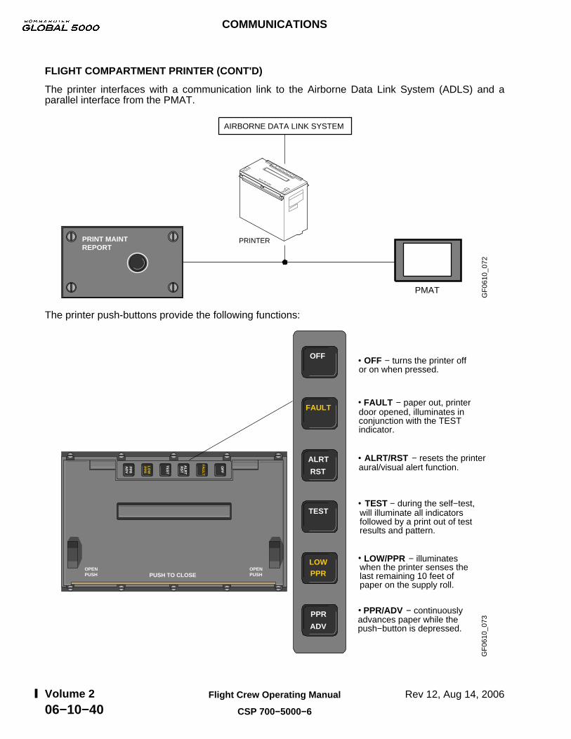
The printer interfaces with a communication link to the Airborne Data Link System (ADLS) and aparallel interface from the PMAT.
GF
0610
_072
PMAT
AIRBORNE DATA LINK SYSTEM
PRINTERPRINT MAINTREPORT
The printer push-buttons provide the following functions:
GF
0610
_073
or on when pressed.
door opened, illuminates in conjunction with the TEST indicator.
aural/visual alert function.
will illuminate all indicators followed by a print out of test results and pattern.
when the printer senses the last remaining 10 feet of paper on the supply roll.
advances paper while the push−button is depressed.
OFF − turns the printer off
FAULT − paper out, printer
ALRT/RST − resets the printer
TEST − during the self−test,
LOW/PPR − illuminates
PPR/ADV − continuously PPR
ADV
LOWPPR
TEST
ALRT
RST
FAULT
OFFF
AU
LT
LOW
PP
R
OPENPUSH PUSH TO CLOSE
OPENPUSH
COMMUNICATIONS
Rev 12, Aug 14, 2006Flight Crew Operating Manual
CSP 700−5000−6
Volume 206−10−40

EICAS MESSAGES
FG
F06
10_0
01
SELCAL HF 1 (2)Annunciated when HF1 or 2 indicates an incoming message.
ELT TRANSMITTINGEmergency locator transmitter is transmitting.
SELCAL VHF 1 (2)(3)
or 2 or 3 indicates an incoming message.
ELT TRANSMITTINGFDR ACCEL FAILFDR FAIL
Annunciated when VHF1
SELCAL HF 1−2SELCAL VHF 1−2−3
FDR FAILFlight Data Recorder has failed.
FDR ACCEL FAILFlight Data Recorder accelerometer has failed.
COMMUNICATIONS
Rev 12, Aug 14, 2006 Flight Crew Operating Manual
CSP 700−5000−6
Volume 206−10−41

COMMUNICATIONS
Rev 12, Aug 14, 2006Flight Crew Operating Manual
CSP 700−5000−6
Volume 206−10−42
THIS PAGE INTENTIONALLY LEFT BLANK

CB - COMM SYSTEM
GF
0620
_002
STAT SYS BUS PREV CNTL TESTPAGE
NEXTPAGE
EMERCNTL
BUS
CIRCUIT BREAKER − SYSTEM 1/2
SYSTEMCIRCUIT BREAKER
AFCS
AIR COND/PRESS
APU
BLEED
CAIMS
COMM
DOORS
ELEC
ENGINE
FIRE
FLT CONTROLS
FUEL
BRT
1/5CB − COMM SYSTEM
2/5CB − COMM SYSTEM
3/5CB − COMM SYSTEM
4/5CB − COMM SYSTEM
5/5CB − COMM SYSTEM
COMMUNICATIONS
EMS CIRCUIT PROTECTION
Rev 2A, Apr 11, 2005 Flight Crew Operating Manual
CSP 700−5000−6
Volume 206−20−1

COMMUNICATIONS
EMS CIRCUIT PROTECTION
Rev 2A, Apr 11, 2005Flight Crew Operating Manual
CSP 700−5000−6
Volume 206−20−2
THIS PAGE INTENTIONALLY LEFT BLANK