bl59a10/s10 photoelectric smode detector ic 1. product
TRANSCRIPT

Shanghai Belling Co., Ltd. BL59A10/BL59S10 Datasheet V1.1
1 / 12
BL59A10/S10 PHOTOELECTRIC SMODE DETECTOR IC
1. Product description 1.1 Basic function:
BL59A10/ S10 is a CMOS LSI used for smoke detection. Ultra-low power analog and
digital circuits are contained in it. Combined with an IR photoelectric chamber,
this IC is used to detect smoke through receiving light scattered by tiny smoke
particles going into the chamber. When smoke is detected, a burst of alarm sounds
are generated by an external piezoelectric buzzer driven by the push-pull output of
this IC.
1.2. Applications:
Smoke detection system.
2. Features Power supply range: 6V ~ 12V
Average supply current: 12uA
Operating temperature range: -10 ~ 60℃
Ideal for battery powered applications.
3. Block diagram of this IC

Shanghai Belling Co., Ltd. BL59A10/BL59S10 Datasheet V1.1
2 / 12
4. Pin assignment

Shanghai Belling Co., Ltd. BL59A10/BL59S10 Datasheet V1.1
3 / 12
5. Pin description
Pin
No. Symbol Input/output Functions
1,2
C1,C2
External
capacitor
connection
By connecting external
capacitor, a voltage feedback
amplifier is formed. The gain of
it is determined by capacitor’s
value.
3
DETECT
I
Detecting input
Connect a photodiode to supply a
signal to the internal
comparator.
4
STROBE
O
Strobe
A strobe voltage output,
referenced to VDD.
When output = VDD -5V, it enables
other internal circuits.
5,14 VDD,GND Power supply To supply the power
6
IRED
O
Output signal
To output pulse drive signal for external NPN transistor which
drives a IR photodiode.
7
I/O
Input/output
It can be used to connect up to
40 detectors to make auxiliary
alarm, remote alarm,
auto-dialer“
8,9
BRASS,SILVER
O
Push-pull
driver’s
output
Push-pull driver outputs signal
to drive external buzzer to
alarm, and to show various
operation states.
10
FEEDBACK
I Feedback
terminal
To feed ‘silver’ signal back to
the push-pull output driver
circuit’s input
11
LED
O
Output signal
It is an open drain output, can
drive LED directly. The LED can
tell the detector’s various
operation states.
12
OSC
I Oscillator’s
input
Connected to external R and C,
which determine the internal
oscillator’s frequency.
13
R1 External R and C
connecting
terminal
Connected to external R and C,
which determine the output pulse
period of IRED.
15
LOW-SUPPLY
I
Low voltage
detecting input
It connected to external
resistor divider between VDD and
LED to get a low supply alarm
threshold voltage
16 TEST I Test terminal This pin is normally low by an
internal pull-down device. When

4 / 12
Shanghai Belling Co., Ltd. BL59A10/BL59S10 Datasheet
it is set high, the IC enters into
a simulated-smoke condition.
When floating, this pin comes
back to VSS (low) by pull-down
device.
6. Function of this IC 6.1. The variable gain photoelectric amplifier is directly connected to IR detector
(photodiode). The amplifier’s gain is determined by external capacitors C1 and C2.
During standby, the amplifier’s gain is at minimum. Under smoke condition, the
amplifier’s gain is at medium. Entering into test condition, the amplifier’s gain
is at maximum. Additionally, under standby state, if the special supervisory circuit
is activated to check the chamber’s sensitivity, the amplifier’s gain is also at its
maximum.
6.2. Using VSS as its reference, the I/O pin can be used to connect up to 40 units together.
When I/O pin is used as an input, its on-chip pull-down resistor can prevent noise from
entering into the unit. Under smoke status, the unit activates I/O driver to send a
signal to its interconnected units to activate remote alarm.
6.3. Display method: LED (connected to LED pin) flashing combined with alarm sound,
indicates a LOCAL SMOKE condition. Only pulsating alarm sound without LED flashing
indicates a REMOTE SMOKE condition.
6.4 Typical Timing
Standby Timing Diagram

5 / 12
Shanghai Belling Co., Ltd. BL59A10/BL59S10 Datasheet
Smoke Timing Diagram
7. Specifications 7.1. Absolute maximum ratings(VSS as reference)
Symbol Parameter Limits Units
VDD Supply voltage -0.5 ~ +12
V
VIN
DC input voltage
C1, C2, Detect -0.25 ~Vdd+0.25
OSC, low-supply trip -0.25 ~Vdd+0.25
I/O -0.25 ~Vdd+0.25
Feedback -15 ~+15
Test -1.0 ~Vdd+0.25
IIN DC input current ±10 mA
IOUT DC output current ±25 mA
IDD Supply current +25/-150 mA
PD Power dissipation in still air, 5Sec 1200
mW Continuous 350
TSTG Storage temperature -55 ~125 ℃
TL Soldering temperature 260 ℃

6 / 12
Shanghai Belling Co., Ltd. BL59A10/BL59S10 Datasheet
7.2 DC Electrical characteristics(Ta = 25 ℃ , VSS as reference, unless otherwise
indicated)
Symbol Parameters Test condition VDD Min. Max. Unit
VDD Power supply voltage range -- 6.0 12 V
VTH Supply threshold voltage,
Low supply alarm voltage
Low supply trip
voltage
VIN = VDD/3
6.5
7.8
V
IDD
Average supply current
Standby,
(See sample
figure)
12
--
12
uA
iDD
Supply peak current
Strobe on,
IRED off
(See sample
figure)
12
--
2.0
mA
VIL
Low level input voltage,
I/O
Feedback
Test
9.0
9.0
9.0
1.5
2.7
7.0
V
VIH
High level input voltage
I/O
Feedback
Test
9.0
9.0
9.0
3.2
6.3
8.5
V
IIN
Input current OSC,
Detect
Low supply trip
Feedback
VIN = VSS or VDD
VIN = VSS or VDD
VIN = VSS or VDD
12
12
12
±100
±100
±100
nA
IIL Low level input current
TEST VIN = VSS 12 -1
uA
IIH
Pull-down current Test
I/O
VIN = VDD
No local smoke, VIN
= VDD
No local smoke,
VIN = 17V
9.0
9.0
12
0.5
25
--
10
100
140
uA
VOL
Low level output voltage,
LED
Silver, Brass
IOUT = 10mA
IOUT = 16mA
6.5
6.5
0.6
1.0
V
VOH High level output voltage
Silver, Brass IOUT = -16mA
6.5
5.5 -
V
VOUT
Output
voltage
(See pin
description)
Strobe
Inactive,
IOUT = -1uA
Active, IOUT =
100uA to 500uA
(load regulation)
-
9.0
VDD -0.1
VDD -4.4
Vdd-5.6
V

7 / 12
Shanghai Belling Co., Ltd. BL59A10/BL59S10 Datasheet
IRED
Inactive,
IOUT =-1uA
Active, IOUT =6uA
(load regulation)
-
9.0
-
2.2
5
0. 1
3.75
IOH
High-level output current,
I/O
Local smoke,
VOUT =4.5V 6.5 -4 --
mA
Local smoke,
VOUT = VSS
(short-circuit
current)
12
--
-16
IOZ
Output off-state leak
current,
LED
VOUT = VSS or VDD
12
-
±1
uA
VIC
Common-mode voltage range
C1, C2, Detect
Local smoke,
Pushbutton test or
chamber
sensitivity test
--
VDD -4
VDD -2
V
VREF
Internal reference voltage
of smoke comparator
Local smoke,
pushbutton test or
chamber
sensitivity test
--
VDD-3.08
VDD-3.92
V
7.3 AC Electrical characteristics(Ta = 25 ℃ , VSS as reference, unless otherwise
indicated, Vdd=9V,R1=100kΩ,C3=1500pF,R2=10MΩ)
No Symbol Parameter Conditions Clock Min. Max. Unit
1 1/fosc OSC Period* Free-Running Sawtooth
Measured at Pin12 1 9.5 11.5 ms
2 Tled
Led Pulse
Period
No Local and Remote Smoke 4096 38.9 47.1 s
3 Tled Remote Smoke,But no
LocalSmoke Only - None s
4 Tled Local Smoke or
Pusgbutton Test 64 0.6 0.74 s
5
Tw(led,stb))
Led and
strobe Pulse
Width
1
9.5
11.5
ms
6 Tired1
Ired Pulse Period
Smoke Test 1024 9.67 11.83 s
7 Tired2 Chamber sensitivity Test without Local Smoke
4096 38.9 47.1 s
8
Tired3
Pusgbutton Test
32
0.302
0.37
s
9 Tw(ired) Ired Pulse Width
Tf* 94 116 us
10 Tr Ired Rise Time - - 30 us Tf Ired Fall Time - - 200 us
11
Tmod
Sliver and Brass Modulation Period
Local or Remote Smoke
-
297
363
ms
11,12
Ton/Tmod Sliver and Brass Duty Cycle
Local or Remote Smoke
-
73
77
%

8 / 12
Shanghai Belling Co., Ltd. BL59A10/BL59S10 Datasheet
C4 BT1
47uF 9V
4.7to22
C1 Test
C2 LowSupplyTrip
Detect Vss
Strobe R1
Vdd Osc
IRED LED
I/O Freedback
Brass SILVER
2
15
* 250K
D2
3 10M
C3
9
3
2
1
1k A
C5
VDD
R8* D1
VDD
TEST R9*
R7
C1 47n
5k C2 4.7n
R11
R14 6.8K 1 16
R10 R2
VDD
14
IR Detector 4 13
R1 100K
R6
R12 D3 VDD VDD
Q1
5 12 1500pf
R3
470 D4
IR Emitter
R13*
6 11 A Visible LED
100uF U2 7 10
R4* 100K
C6 8 0.01uf
R5*
2.2M BUZZER
com
13
Tch
Sliver and Brass Chirp Pulse Period
Low Supply or Degraded
Chamber Sensetivity
4096
38.9
47.1
s
14
Tw(ch)
Sliver and Brass Chirp Pulse Width
Low Supply or Degraded
Chamber Sensetivity
1
9.5
11.5
ms
15
Trr
Rising Edge on I/O to smoke Alarm Response Time
Remoke Smoke, no Local Smoke
-
-
800
ms
16
Tstb
Strobe Out Pulse Period
Smoke Test 1024 9.67 11.83 s
17 Chamber sensitivity Test without Local Smoke
4096 38.9 47.1 s
18 Low Supply Test without Local Smoke
4096 38.9 47.1 s
19 Pushbutton Test - 0.302 0.37 s
OSC Period T(=Tr+Tf)is determined by the external R1 ,R2,and C3,where Tr=(0.6931)R2*C3
and Tf=(0.6931)R1*C3
8. Application sample figure
VDD
4.7K
6.
8k
47K
10
0K
9 / 12
Shanghai Belling Co., Ltd. BL59A10/BL59S10 Datasheet
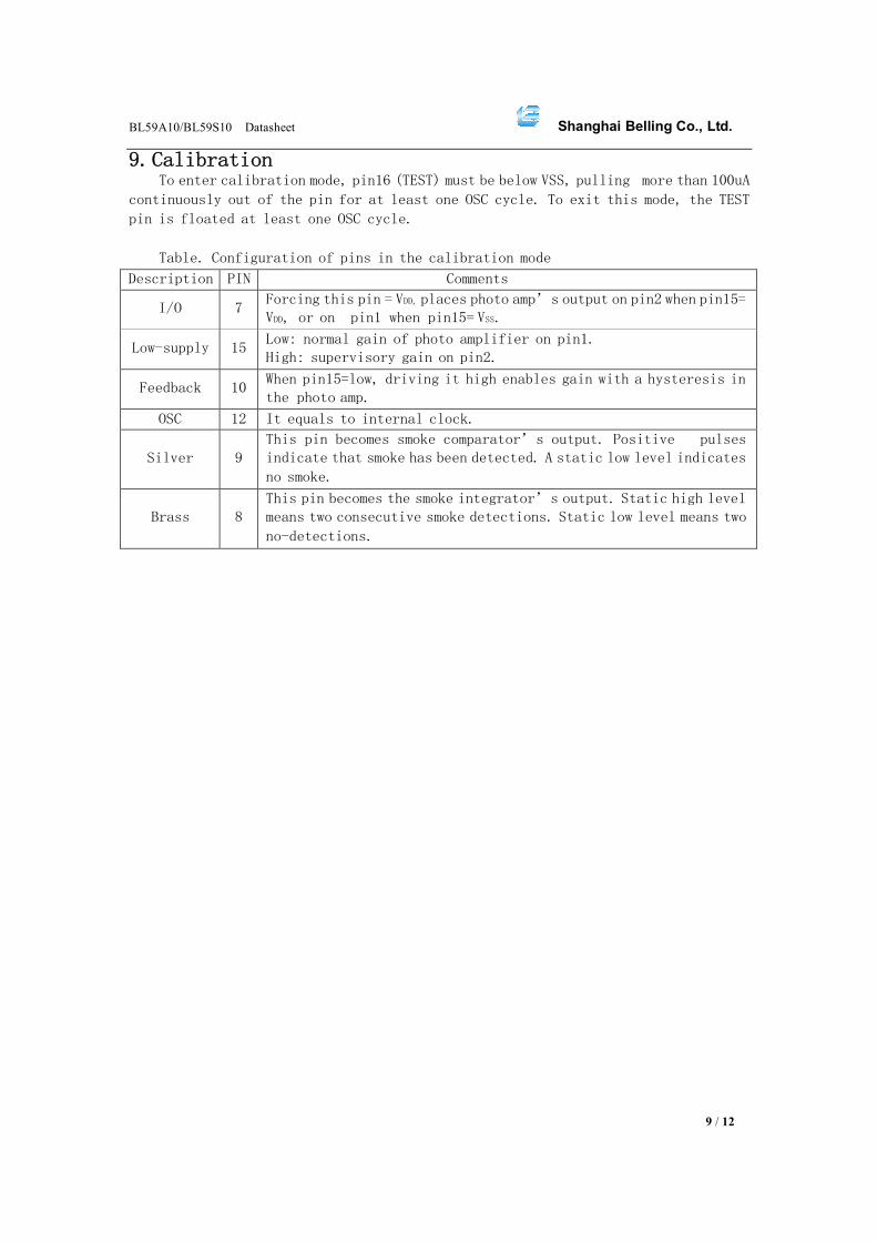
9. Calibration To enter calibration mode, pin16 (TEST) must be below VSS, pulling more than 100uA
continuously out of the pin for at least one OSC cycle. To exit this mode, the TEST
pin is floated at least one OSC cycle.
Table. Configuration of pins in the calibration mode
Description PIN Comments
I/O 7 Forcing this pin = VDD, places photo amp’s output on pin2 when pin15=
VDD, or on pin1 when pin15= VSS.
Low-supply 15 Low: normal gain of photo amplifier on pin1.
High: supervisory gain on pin2.
Feedback 10 When pin15=low, driving it high enables gain with a hysteresis in
the photo amp.
OSC 12 It equals to internal clock.
Silver
9
This pin becomes smoke comparator’s output. Positive pulses
indicate that smoke has been detected. A static low level indicates
no smoke.
Brass
8
This pin becomes the smoke integrator’s output. Static high level
means two consecutive smoke detections. Static low level means two
no-detections.

10 / 12
Shanghai Belling Co., Ltd. BL59A10/BL59S10 Datasheet
PACKAGE DIP16

Shanghai Belling Co., Ltd. BL59A10/BL59S10 Datasheet
11/12
SOP16

Shanghai Belling Co., Ltd. BL59A10/BL59S10 Datasheet
12/12
SOP16W