big area additive manufacturing application in wind
TRANSCRIPT
BIG AREA ADDITIVE MANUFACTURING APPLICATION IN WIND TURBINE
MOLDS
Brian K. Post, Bradley Richardson, Randall Lind, Lonnie J. Love, Peter Lloyd, Vlastimil Kunc,
Breanna J. Rhyne, Alex Roschli, *Jim Hannan, *Steve Nolet, *Kevin Veloso, **Parthiv Kurup,
** Timothy Remo, and **Dale Jenne
Manufacturing Demonstration Facility, Oak Ridge National Laboratory, Knoxville, TN 37932,
USA
*TPI Composites, Inc. PO Box 367, 373 Market Street, Warren, RI 02885, USA
** National Wind Technology Center, National Renewable Energy Laboratory, Boulder, CO
80303, USA
Abstract
Tooling is a primary target for current additive manufacturing (AM), or 3D printing,
technology because of its rapid prototyping capabilities. Molds of many sizes and shapes have
been produced for a variety of industries. However, large tooling remained out of reach until the
development of large-scale composite AM manufacturing processes like the Big Area Additive
Manufacturing (BAAM) system. The Department of Energy’s Oak Ridge National Laboratory
(ORNL) worked with TPI Composites to use the BAAM system to fabricate a wind turbine blade
mold. The fabricated wind turbine blade mold was produced in 16 additively manufactured
sections, was 13 meters long, had heating channels integrated into the design, and was mounted
into a steel frame post fabrication. This research effort serves as a case study to examine the
technological impacts of AM on wind turbine blade tooling and evaluate the efficacy of this
approach in utility scale wind turbine manufacturing.
Introduction
The purpose of this paper is to identify potential use of Additive Manufacturing (AM) in the
production of composite parts for wind energy systems.
AM, more commonly referred to as 3D printing, is a fast-growing industry in which recent
technological advances have expanded its use beyond rapid prototyping. AM encompasses
techniques applicable across multiple material types—most commonly polymers, metals,
composites, and ceramics—that use computer-rendered designs to produce a near-net-shape part,
layer by layer. Current costs for both polymer-based and metal-based AM systems keep AM out
of large-volume production, but advancements in AM techniques will lower per-unit costs
and advance designs beyond the capabilities of current conventionally manufactured (CM)
components.
In the wind industry, current and research and development-level (R&D) AM
technologies have potential for considerable impact on the prototyping and manufacturing cost of
wind energy tooling and components. In the future, AM technologies could enable on-site
manufacturing of turbine components as well as production of site-optimized components that
are tailored to the unique wind and grid resources of a given location. For example, lower-cost
2430
Solid Freeform Fabrication 2017: Proceedings of the 28th Annual InternationalSolid Freeform Fabrication Symposium – An Additive Manufacturing Conference
Reviewed Paper

and faster production of blade molds can increase the rate at which industry prototypes and
conducts full-scale field testing of novel designs. Easier prototyping opportunities could be
extended to customized nacelle designs and turbine configurations. AM could be used to create
specialized tooling for the manufacturing of conventional components. AM will also allow for
the development of components designed to better suit the specifications of their use, including
lower materials requirements.
Insights gained from this project can be applied to the manufacture of other components for
wind energy systems. Additional analysis of AM’s current and newly-designed wind system
components, the use of alternative materials, and on-site manufacturing potential is
recommended. Rapid development of polymer and metal AM capabilities continue to cause costs
to decline, which makes finding break-even points of AM and CM parts a constant moving
target. Future R&D and analysis will further identify cost reduction opportunities and limits to
AM applications.
Big Area Additive Manufacturing
Conventional fused deposition modeling is based on melting and extruding a filament of
thermoplastic feedstock. Prior work shows that the peak flow rate is limited by the rate at which
the filament can be melted [1]. For larger print volumes (at least 15 times the build volume of
desktop-size consumer-level AM systems), technologies are developing. For example, Cincinnati
Incorporated partnered with ORNL to developed the Big Area Additive Manufacturing (BAAM)
process in 2014, which scales the extrusion process from desktop-sized AM systems of 1-5 cubic
inches per hour to over 1000 cubic inches per hour [2]. To achieve high print rates, material
pellets are used, which also significantly lowers the material cost (from $110 – $220/lb to $3 –
$5 / lb), in combination with an optimized feed screw that reduces throttling of the pellet flow
into the material. BAAM is an extrusion process that uses injection molding material for the
feedstock and a single screw extruder for melting and metering the flow rate (see Figure 1) [3].
A gantry system, commercialized by Cincinnati Incorporated (see Figure 2), moves the extruder
in x, y, and z directions to build the part. The extruder is capable of delivering 100 lbs/hour of
thermoplastic materials from pellet feedstock. The gantry system is capable of achieving 200
inch/sec peak velocities with 64.4 in/s2 accelerations and position accuracy in the 0.002”. The
use of carbon fiber reinforcement in the thermoplastic resins increases the part strength and
stiffness [4]. Just as important, carbon fiber reinforcement also increases thermal conductivity
and reduces the coefficient of thermal expansion lessening the need for a heated chamber to
produce large parts (see Figure 3 and Figure 4) [5]. The elimination of the oven significantly
decreases the energy intensity, which is the manufacturing energy required per kilogram of
product. As shown in Figure 5, conventional FDM systems with heated chambers have a 100
kW-hr/kg energy intensity. Desktop systems that have similar production rates have a 5.5 kW-
hr/kg energy intensity suggesting that the oven accounts for 95% of the energy consumption in
FDM production. BAAM further reduces the energy intensity to 1.1 kW-hr/kg by significantly
increasing productivity from 1 ci/hr to 2500 ci/hr, and BAAM parts are manufactured at room
temperature. Due to its higher build rates and build sizes, BAAM’s initial targeted applications
is in the tooling industry. Specifically, in large, complex injection molds that are needed to
produce CM polymeric and metal parts at a low cost.
2431

Figure 1: BAAM Extruder
Figure 2: Cincinnati BAAM
Figure 3: Section of wind turbine mold
Figure 4: Printed prototype house
2432

Figure 5: Energy intensity for manufacturing
Therefore, the combination of lower energy intensity, higher productivity, and lower
material cost suggests that there will be a significant production cost reduction with BAAM
when compared to conventional AM systems.
Applications of Current Additive Manufacturing Systems in Wind Power Systems:
Fabricating Blade Molds
AM is hindered by limited production rates, expensive materials, processing costs, and small
build volumes. These conditions serve to significantly limit the applicability of AM to wind
energy system production. Commercial turbines are large systems where individual components
often exceed 50 meters in length. The sheer size and mass of these components combined with
throughput requirements largely preclude the application of current AM technology in wind
power manufacturing.
However, several application areas have been identified where economic and technological
incentives make AM processes viable for current production. Furthermore, if wind applications
were used as a target to drive the development of AM systems, more applications with
significant economic benefits become achievable.
The first identified wind application for AM, and the target of this study, is in the
manufacture of molds for wind turbine blades. As described previously, tooling is a primary
target for the current state of AM technology given the less stringent requirements for material
2433
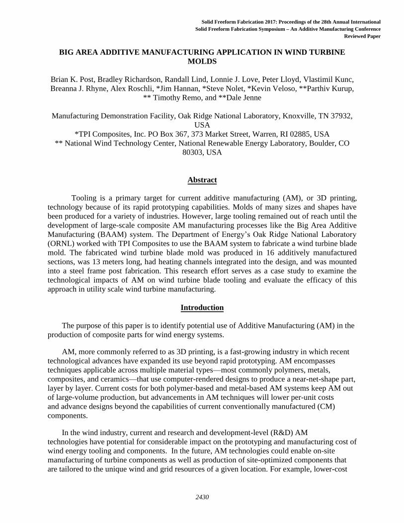
performance and certification. AM molds of various sizes and shapes have been produced for a
variety of industries. Large tooling, however, remained out of reach until the development of
large scale composite AM processes like the BAAM-CI. Figure 6 shows the ORNL/TPI AM
blade mold demonstrator produced as a collaboration between ORNL and TPI and funded by
DOE’s Advanced Manufacturing and Wind and Waterpower Offices.
Figure 6: Additively manufactured blade mold and produced blade section.
The traditional blade mold manufacturing process is a multi-step, expensive operation.
First, a plug is manufactured by subtractive machining of foam and tooling resin. This multi-
piece assembly takes several weeks to months to produce from CAD drawings that are then used
to generate CNC toolpaths. From there, the plug is shipped to the mold manufacturer where it is
qualified and aligned. The mold manufacturer then applies a release agent and lays up fiberglass
of sufficient thickness to support the molding operations. Miles of heating wire is manually
embedded in the underside of the mold and arranged in zones of similar area. Then a steel frame
is manually erected and attached to the mold prior to removal from the plug. From one plug set,
up to eight molds can be produced amortizing the cost. For the production of one prototype
mold, or a small set of molds, this cost can be prohibitively expensive, often reaching millions of
dollars.
ORNL- TPI Scaled Wind Farm Technology (SWiFT) Facility Mold
To study the effect of wakes in large wind farms, the Sandia SWiFT facility uses a scaled
wind farm. These turbines require custom blades to simulate the dynamics of their larger
counterparts. The blades are scheduled to be produced using additively manufactured molds
produced in partnership between ORNL and TPI and funded by the Department of Energy’s
(DOE) Advanced Manufacturing (AMO) and Wind and Water Power Office (WWPO). This
research effort serves as a case study to examine not only the technological impacts of AM on
2434

wind blade production, but also the economics of AM at the large scale using BAAM
technology.
Mold Requirements and Risk Reduction Exercise
The first step to the project was to define the mold requirements. For the resin infusion, there
were a number of critical performance targets for the mold necessary to successfully
manufacture blades. These targets included operating temperature, temperature gradients across
the surface of the molds during service, mold distortion, vacuum, and life. The team identified
three goals for each metric. The first was the target necessary for the success of the project. The
second was a stretch goal that, if passed, would qualify the process for low volume production.
Finally, the ultimate goal for the technology was to meet the targets necessary for full scale
production. The metrics and goals for the project are outlined in Table 2.
Table 2: Project Metrics and Goals
The first phase of the project focused on risk reductions steps. The team designed a series of
experiments to ensure that the BAAM molds would achieve the targets. High risk items included
the heating (achieving the target temperatures and temperature gradients), distortion, and vacuum
integrity. In terms of vacuum integrity, the team elected to coat the printed mold with fiberglass.
The mold was designed 4 mm under the target mold lines. TPI coated the molds with 8 mm of
fiberglass that was then machined to the final surface geometry and finish. The second item was
the heating of the mold. It was determined that additive manufacturing could enable a very
novel approach to heating. Rather than manually inserting miles of conductive heating wires, the
molds could be designed with ducting directly printed into the structure. Small heating elements
and blowers could be easily and rapidly installed in the molds, taking the time for installation of
heaters from weeks and even months to a single day.
2435

Table 2: Performance Metrics and Goals
Figure 7: Integrated ORNL/TPI heater units in blade mold section
Figure demonstrates the arrangement of heater units in the SWiFT mold set for the
uniform heating of the mold surface. Each channel has been designed to be of equal surface area
to reduce non-uniformity of the temperature profile over the surface of the mold. Hot air is
circulated through the mold until the surface temperature reaches the desired set point; then the
set point is lowered to a maintenance level.
Figure 8: Airflow in mold section
A cross sectional view of the second mold section is shown in Figure 8. Arrows
illustrates the heat flow, in that hot air exits the heater unit and flows along the surface of the
mold where it loses energy and recirculates forming a closed loop. The functional structure of the
AM component is used not only to achieve the desired surface geometry, but also to provide a
housing for the heating unit and to distribute the heat uniformly throughout the structure. AM, in
this example, enables functional structure and eliminates the manual labor associated with the
emplacement of the heating system. Furthermore, a failed heating unit is easily replaceable via a
pocket on the underside of the return channel.
2436

A single section was manufactured and evaluated for performance (see Figure 9). A
series of experiments were conducted to evaluate the performance (distortion, temperature
gradient, vacuum integrity) of the mold. A laser tracker (see Figure 10) profiled the accuracy of
the mold at room temperature. The heaters were turned on and the system was then brought up
to the target temperature. At target temperature, the laser scanner measured the hot surface
profile, and thermal imaging cameras measured the temperature gradients across the surface (see
Figure 11, Figure 12, and Figure 13). The temperature gradient was measured at +/- 3C at 40C
exceeding the requirements for the stretch goal. As shown in Figure 14, surface variations are
under +/-0.025”, approximately 0.1% of the chord. In terms of vacuum, the system exceeded the
target of 15 mbar over 60 minutes. Therefore, the risk reduction exercise demonstrated that the
AM mold sections exceeded the stretch goal requirements.
Figure 9: Test section
Figure 10: Laser tracker
2437

Figure 11: Thermal imaging camera
Figure 12: Output of thermal imaging camera and thermocouples
2438

Figure 13: Thermocouple output
Figure 14: Measured surface variation at molding temperature
Printed Mold Manufacturing
After successfully achieving the goals through the risk reduction exercise, the project
transitioned to the development of a full scale 13 m blade mold. From a manufacturing
perspective, the mold proved to be better suited for vertical printing (see Figure 15). The work
volume in the BAAM system was 8 ft wide, 20 ft long, and 6 ft in height. Therefore, each mold
was made from eight segments (see Figure 16) , printed one at a time except for the smaller tip
sections which were printed in twos.
2439

Figure 15: Printed low pressure side section 1 in the BAAM CI printer
Figure 16: Mold sections
2440

Figure 17: ORNL/TPI AM blade mold conceptual model
Each section is printed on end to maximize the resolution of the BAAM process and
reduce the required support material as shown in Figure 15. Figure 18 shows the sections of the
SWiFT AM blade mold printed prior to covering it with fiberglass. While many of the technical
opportunities of AM in wind mold production are addressed in the production of the SWiFT
mold, it also serves as a tool for the evaluation of economic incentives for similar molds on
larger scales.
Figure 18: 5 of the 8 low pressure side SWiFT mold sections
2441

After completion of printing, the molds were coated with fiberglass (see Figure 19) and
machined to the final target surface (see Figure 20). The molds were fitted to be inserted into the
egg crate structure (Figure 21) and were finally polished for operation (Figure 22). As of the
writing of thispaper, one full set of blades has been manufactured (see Figure 23, three in total)
with no discernable wear on the molds.
Figure 19: Fiberglass surfaced printed component
Figure 20: Section being machined
2442

Figure 21: Assembly in egg crate
Figure 22: Final molds (high pressure and low pressure)
2443

Figure 23: Finished blade
Conclusions and Future Applications
AM is finding more and more industrial applications in the area of molds, jigs, and
fixtures. The automotive, aerospace, and appliance industries are rapidly transitioning to printed
tools because of the complexity, high cost, and long lead times associated with these parts.
In terms of scale, there are new equipment manufacturers developing systems that are one
to two orders of magnitude larger and faster than the current abilities of the Cincinnati
BAAM. Ingersoll Machine Tool company announced the partnership with ORNL to develop
the Wide High Additive Manufacturing (WHAM) system, see Figure 24 and Figure 25. The
system will have a build volume that is approximately 25 feet wide, 20 feet tall, and 100 feet
long and is scalable to much larger dimension. The production rate will start at 1000 lb/hr but is
scalable to higher rates. This scale system enables the direct manufacture of parts (molds,
blades, nacelles, etc.) that are competitive with current wind manufacturing needs.
2444

Figure 24: Front view WHAM
Figure 25: Rear view WHAM
Given significant leaps in material properties and out of plane printing, there is potential
to directly manufacture wind turbine blades (see Figure 27). First, from the materials
perspective, everything used to date in the BAAM process is based on short chopped carbon
fiber. These materials are ideal for tooling because of their high stiffness, but they do not have
the strength needed for strength limited structural applications. There will be a need for long or
continuous fiber reinforcement to directly manufacture wind turbine blades. In addition, to keep
part weight down, it will be necessary to print core structures (such as foam) to achieve specific
strength and stiffness requirements. Systems such as the WHAM will have the ability to print,
machine, and coat all within one machining center. At rates of 1000 lb/hr and greater, it is
feasible to envision rapid automated manufacturing of customized wind turbine blades with
multi-material (carbon fiber, glass fiber, foam, etc.) solutions.
Figure 26: 3D printed wind turbine blade
2445

Acknowledgements
This work was sponsored in a joint partnership by the Department of Energy’s Energy
Efficiency and Renewable Energy’s Advanced Manufacturing Office and Wind and Water
Power Technology Office. Cost share was provided by TPI composites in accordance with the
Cooperative Research and Development Agreement. Matthew Sallas was integral to the
fabrication and machining of the printed mold segments and this work would not have been
possible without his hard work.
References
[1] Monzon, M., , Gibson, I., Benitez, A., Lorenzo, L., Hernandez, P., Marrero, M. (2013).
"Process and material behavoir modeling for a new desig of micro-additive fused deposition."
International Journal of Manufacturing Technology 67: 2217-2726.
[2] R.G. Zorrilla, 3D Print. (2013) 1–5.
[3] Holshouser, C., C. Newell, S. Palas, L. J. Love, V. Kunc, R. F. Lind, P. D. Lloyd, J. C.
Rowe, C. A. Blue and C. E. Duty (2013). "Out of bounds additive manufacturing." Advanced
Materials and Processes 171(3).
[4] Tekinalp, H. L., V. Kunc, G. M. Velez-Garcia, C. E. Duty, L. J. Love, A. K. Naskar, C. A.
Blue and S. Ozcan (2014). "Highly oriented carbon fiber–polymer composites via additive
manufacturing." Composites Science and Technology 105: 144-150.
[5] Love, L. J., V. Kunc, O. Rios, C. E. Duty, A. M. Elliott, B. K. Post, R. J. Smith and C. A.
Blue (2014). "The importance of carbon fiber to polymer additive manufacturing." Journal of
Materials Research 29(17): 1893-1898.
[6] Salmi, E. A. a. A. (2012). "Economics of Additive Manufacturing for End-Use Metal Parts."
International Journal of Advanced Manufacturing Technology: 1147-1155.
2446