bhma - davis-inc.com · bhma builders hardware manufacturers asscx:iation builders hardware...
TRANSCRIPT

ANSIIBHMA A156.10-2011Revision of ANSIIBHMA A156.10-2005
STANDARD
FOR
POWER OPERATED PEDESTRIAN DOORS
SPONSOR
••••BHMAbuilders hardware manufacturers
asscx:iation
BUILDERS HARDWARE MANUFACTURERS ASSOCIATION, INC.
American National Standards InstituteApproved August 2, 2011

AMERICAN NATIONAL STANDARD
An American National Standard implies a consensus of those substantially concerned with its scope andprovisions. An American National Standard is intended as a guide to aid the manufacturer, the consumerand the general public. The existence of an American National Standard does not in any respect precludeanyone, whether he has approved the standard or not, from manufacturing, marketing, purchasing, or usingproducts, processes, or procedures not conforming to this standard. American National Standards aresubject to periodic review and users are cautioned to obtain the latest editions.
CAUTION NOTICE: This American National Standard is permitted to be revised or withdrawn at anytime. The procedures of the American National Standards Institute require that action be taken to reaffirm,revise, or withdraw this standard no later than five years from the date of publication. Purchasers ofAmerican National Standards receive current information on all standards by calling or writing theAmerican National Standards Institute.
Published byBUILDERS HARDWARE MANUFACTURERS ASSOCIATION, INC.
355 Lexington Avenue New York, New York 10017
Copyright © 2011 by theBuilders Hardware Manufacturers Association, Inc.
www.buildershardware.com
Not to be reproduced without specific authorization from BHMA
Printed in the USA
This Standard was approved by ANSI under the Canvass Method. BHMA was accredited on 21 March1983 by ANSI as a sponsor using the Canvass Method.
2

FOREWORD(This Foreword is not a part of ANSIIBHMA A156.10)
The general classification of builders hardware includes a wide variety of items which are divided intoseveral categories. To recognize this diversity, a sectional classification system has been established.Power Operated Doors is one such section and this Standard is a result of the collective efforts of membersof the Builders Hardware Manufacturers Association, Inc. who manufacture this product. The total ProductStandards effort is, therefore, a collection of sections, each covering a specific category of items.
Performance tests and, where necessary, dimensional requirements have been established to ensurea degree of safety. There are no restrictions on design except for those dimensional requirements imposedfor reasons of safety.
This Standard is not intended to obstruct but rather to encourage the development of improvedproducts, methods and materials. The BHMA recognizes that errors will be found, items will becomeobsolete, and new products, methods and materials will be developed. With this in mind, the Associationplans to update, correct and revise these Standards on a regular basis. It shall also be the responsibility ofmanufacturers to request such appropriate revisions.
3

TABLE OF CONTENTS
1. GENERAL 5
2. DEFINITIONS OF TERMS USED IN THIS STANDARD.....................................................•..••.....................•..........6
3. SWINGING DOORS 8
4. SLIDING DOORS 8
5. FOLDING DOORS 8
6. GUIDE RAILS 9
7. CONTROL MATS REQUIREMENTS 10
8. SENSORS............................................•••••...•••.........••.••••••••..••...•...............•....................................•................••.•.••.........12
9. KNOWING ACT DOOR ACTIVATION 16
10. ENTRAPMENT PROTECTION 18
11. SIGNAGE........................................•.......••••..•..............••.•.••..•..............................•..................••••••.................................19
12 BREAK AWAY EGRESS TEST FOR SWINGING, FOLDING AND SLIDING DOORS 20
APPENDIX A 24
APPENDIX B................••••.••••••.••.................................................•••.•••...............•.•.•...............................•••..................•............46
APPENDIX C 49
APPENDIX D 52
APPENDIX E ••...•.............•............................•.....•.....•.........••••••••••................................................•..•.•.•..•................................52
4

1. GENERAL
1.1 Scope Requirements in this Standard apply to power operated doors for pedestrian use whichopen automatically when approached by pedestrians and some small vehicular traffic or by a knowingact. Included are provisions to reduce the chance of user injury or entrapment. Power operated doorsfor industrial or trained traffic are not covered in this Standard.
1.1.1 Where this Standard contains specifications relating to minimum or maximum dimensions ofvarious components of power operated doors for pedestrian use and some small vehicular traffic, suchdimensions are included to provide user protection for what are, in the industry, standard applicationconditions. This Standard does not apply to custom installations.
1.2 This Standard does not apply to power assist and low energy power operated doors. Refer toANSI/BHMA A156.19 for Power Assist and Low Energy Power Operated Doors.
1.3 Required dimensions are expressed in US units first; approximate metric equivalents follow inparentheses. The following is a conversion chart for inches to approximate mm equivalents where notgiven in the standard.
TO CONVERT INCHES TO MILLIMETERS, MULTIPLY INCHES BY 25.4TO CONVERT MILLIMETERS TO INCHES, MULTIPLY MILLIMETERS BY 0.03937.
Inches mm Inches mm Inches mm Inches Mm
1/16 1.6 6 152 23 584 45 11431/4 6.35 7 178 24 610 47 11941/2 12.7 8 203 25 635 48 12193/4 19 9 229 26 660 49 1245
1 25.4 10 254 27 686 50 127011/2 38 11 279 28 711 51 129513/4 45 12 304 30 762 52 132111/2 38 13 330 31 787 53 1346
2 51 14 356 32 813 54 13722.26 57 15 381 33 838 55 1397
21/2 63 16 406 34 864 56 14223 76 17 432 36 914 57 1448
3 3/4 95 20 508 40 1016 58 14734 102 21 533 41 1041 60 15245 127 22 559 43 1092 144 3658
1.4 American National Standards referenced in A156.1O are available from BHMA,www.buildershardware.com or the American National Standards Institute, www.ansi.org..
1.5 Tolerances Where only minus tolerances are given, the dimensions are permitted to beexceeded at the option of the manufacturers. All values which do not carry specific tolerances or arenot marked maximum or minimum shall have the following tolerances: Linear dimensions shall be ±1/16 in (1.6 mm). Pounds or pound force shall be ± 2%. Degrees opening shall be ± 2 degrees.Electrical measurements shall be ± 2%.
1.6 Tests described in this standard are performed under laboratory conditions. Measurements shall
5
be taken under neutral air pressure conditions. In actual usage, results vary because of installation,maintenance and environmental conditions.
1.7 Doors used as fire doors or smoke barriers have additional requirements not covered in thisstandard.
1.8 Where required by the authority having jurisdiction, products meeting the requirements of thisStandard are required to comply with UL 325-Fifth Edition June 2002, and be listed or labeled by anationally recognized independent testing laboratory and be under a periodic examination service.
1.9 Tests described in paragraphs 7.6 and 12 shall be performed under the supervision of a nationallyrecognized independent testing laboratory on preproduction samples prior to acceptance of the designfor production and subsequent installation. Production units shall be under an in-plant follow-upinspection service.
2. DEFINITIONS OF TERMS USED IN THIS STANDARD
2.1 Active Area The area where a sensor or control mat detects presence or motion.2.2 Activating Zone An area created by a sensor or control mat such that the door will open whenthe area is entered by (a) person(s) .2.3 Activating Zone, Secondary An area created by a sensor or control mat such that the door willreactivate or reverse and remain active until the door is almost closed.2.4 Automatic Door Operator A power operated mechanism that is attached to a door for thepurpose of mechanically opening and closing a door upon the receipt of an activating signal.2,5 Back Check The checking or slowing down of the speed of door opening before being fullyopened. (Also called Open Check.)2.6 Balanced Door A door equipped with a hinge which moves the hinge pivot point from the hingestile of the door towards the centerline of the door.2.7 Break Away Device A safety device other than an exit device that permits egress underemergency conditions. (Also called Emergency Release.).2.8 Break Out The process of activating a break away device causing the door or panel to swing inthe direction of egress.2.9 Center Pivoted A door which has the pivot point of the hinge located on the centerline of thedoor thickness.2.10 Clear Opening for Automatic Doors The following is for the purpose of sizing activating andsafety zones. Refer to applicable building codes for means of egress clear width requirements.
Swing Doors - With the door open 90 degrees, the clear opening is measured between the face ofthe door and jamb or jamb stop.
Pair of Swing Doors - With the doors open 90 degrees the clear opening is measured between thefaces of the two open doors.
Sliding or Folding Doors - In the fully opened position, the clear opening is measured from theedge of the leading stile to the jamb or jamb stop if present.
Pair of Sliding or Folding Doors - In the fully opened position, the clear opening is measuredbetween the edges of the leading stiles of the two doors.2.11 Closing Cycle Movement of a swinging, folding or sliding door from the fully open position tothe fully closed position.2.12 Closing Time Time from starting of a door closing until it is at rest fully closed.2.13 Control A unit containing electrical components for automatic control of door operation andoverload protection.
6

2.14 Control Mat An activating or safety device placed on the floor on either side of a doorwaysensing the presence of a person. It is constructed of a rubber like material with slip resistant surfaceand is either recessed into or surface mounted on the floor.2.15 Control Mat, Activating A control mat which when activated causes a door to open.2.16 Control Mat, Safety A control mat which when activated prevents a door from opening or holdsa door open.2.17 Custom Installations Where an installation condition exists such that all of the performancecriteria of this standard cannot be met.2.18 Cycle The action of an automatic door operator starting with activating through opening and fullclosing of (a) door(s).2.19 Door Opening for Automatic Doors The following is for the purpose of sizing activating andsafety zones. Refer to applicable building codes for means of egress clear width requirements.
Swing or Folding Doors (Singles or Pairs) The smallest width dimension of a door opening,measured jamb to jamb.
Sliding Doors Same as clear opening.2.20 Double Egress Swing Doors A pair of doors with no mullion that swing in opposite directions2.21 Face of Door The plane of the highest part of the door exposed to view when the door is closed.Does not include hardware or other applied products.2.22 Exposed Area The visible area of a control mat after the trim is installed.2.23 Finger Guard A device applied at the hinge stile of a door or to the hinge jamb adjacent to thedoor preventing damage to hands or fingers.2.24 Folding Door A pivoted swing panel hinged to a passive panel, the other end of which iscaptured in a guide, thus allowing it to slide as both panels swing into a V shape (the fold).2.25 Guide Rail A separator used with power operated doors for traffic separation and control.2.26 Inactive Area The area where a sensor or control mat does not detect presence or motion.2.27 Knowing Act With reference to the act of operating a door operator, such as pressing a switch withthe knowledge of what will happen.2.28 Latch Check The checking or slowing down of the speed of closing a door before being fullyclosed. (Also called Close Check.)2.29 Offset Hung A door which has a hinge pivot point located off the centerline of the doorthickness.2.30 Motion Sensor A sensor designed to detect the movement of a person in the vicinity of thedoorway and give a control signal to the power operated door.2.31 Power Operated Door The combination of door, operator and controls constituting the system.(Also called Automatic Door.)2.32 Presence Sensor A sensor designed to detect the presence of a stationary person in the vicinityof the doorway and give a control signal to the power operated door.2.33 Safety Zone An area of detection provided by presence sensors or control mats on swinging orfolding doors.2.34 Small Vehicular Carts used to transport people or objects.2.35 Telescoping Sliding Doors A type of sliding door with two or more leaves that slide in the samedirection, and arrive at the full open position at the same time.2.36 Threshold A floor mounted horizontal member installed beneath a closed door or in a clear dooropening.2.37 Trained Traffic People trained in the safe use and operation of a particular automatic doorinstallation.2.38 Trim, Mat Material installed around the perimeter of a control mat securing it to the floor.
7
Section 6Section 7 or 8Section 9Section 10Section 11
Section 6Section 7 or 8Section 9Section 10Section 11
3. SWINGING DOORS
3.1 Automatic swing door systems have a variety of configurations, including:• a single door swinging in or out, left-handed or right-handed• a pair of doors simultaneously swinging in the same direction• a pair of doors simultaneously swinging in opposite directions (double egress)
3.2 The door operator is concealed or surface applied. The doors are center pivoted, offset hung,balanced or hinged. No matter what the configuration or system, automatic swinging doors shallinclude guide rails, sensors or control mats, and signage for the safety and convenience of the useraccording to the following:
Guide RailsControl Mats or SensorsKnowing Act (when applicable)EntrapmentSignage
4. SLIDING DOORS
4.1 Automatic sliding doors are flat panels that slide horizontally and linearly. These systems havesuch a variety of configurations that symbols have been assigned to the individual panels that make upan entryway. See Table 1 for definitions of 0, SO, X, SX and P panels.
4.2 No matter what the configuration or system, automatic sliding doors shall include sensors orcontrol mats, and signage for the safety and convenience of the user according to the following:
Control Mats or Sensors Section 7 or 8Knowing Act (when applicable) Section 9Entrapment Section 10Signage Section 11
5. FOLDING DOORS
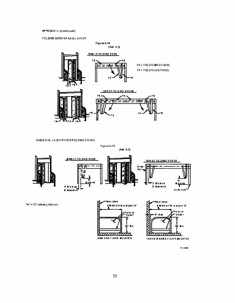
5.1 Automatic folding doors are comprised of two or more separate panels, of which one panel swings,and the other panel slides in a guide. Because of the number of leaves involved, see Figure A-14 fordefinitions of FX and FS panels.
5.2 Automatic folding doors include a variety of configurations, including:• a single folding door folding in or out, left hand or right hand• a pair of doors simultaneously folding in or out, left hand and right hand
5.3 No matter what the configuration or system, automatic folding doors shall include guide rails,sensors or control mats, and signage for the safety and convenience of the user according to thefollowing:
Guide RailsControl Mats or SensorsKnowing Act (when applicable)EntrapmentSignage
8
6. GUIDE RAILS
6.1 Guide Rails for Swing Doors (See Figures A-I, A-2, A-3, A-4, A-II, AI2-A,B,C, AI9-A,B,C)
6.1.1 Two guide rails shall be installed on the swing side of each door. Single doors shall have oneon each side of the door and pairs or double egress shall have one rail on each hinge side. Rails shallproject at least to the leading edge of the widest door in the fully open position.Exception #1: A wall or separator is permitted to be used in place of a rail, provided that it meets thecriteria in 6.1.2 through 6.1.5Exception #2: Guide rails for swinging doors serving both egress and ingress shall project out fromthe face of the door jambs on the swing side to no less than the outside leading edge of the open doorplus 55 in. (See Figures A-2, A-4 &A-12A,C.)Exception #3 If double egress doors or a pair of doors are installed in a hallway, no guide rails arerequired if the distance between the wall and the door in the 90 degree open position does not exceed10 in. (A-19 A,B,C)Exception #4 Guide rails for Knowing Act swinging doors serving both egress and ingress shallproject out from the face of the door jambs on the swing side to no less than the outside leading edge ofthe open door plus 12 in.
6.1.2 A guide rail shall be 30 in. high minimum measured from the finished floor surface.
6.1.3 A guide rail shall have a panel or a divider to inhibit access to the protected area.
6.1.4 There shall be 6 in. maximum clearance between the rail and the door in the fully openposition or between the rail and the leading edge of the door at the point in its arc of travel when it isclosest to the rail. There shall be a 2 in. minimum clearance between the rail at the hinge side and thedoor in the fully open position.
6.1.5 Free standing guide rails shall have a maximum dimension between the rail and jamb (orother adjacent surface) of 6 in.
6.2 Guide Rails for Folding Doors (See Figures A-14, A-15, A-16, A-17-A,B,C,D)
6.2.1 Two guide rails shall be installed on the fold side of the door. Single doors shall have one oneach side of the door; pairs shall have one rail on each hinge side and shall project beyond the foldopen position not less than 12 in.Exception: A wall separator is permitted to be used in place of a rail, provided that it meets thecriteria in 6.1.2 through 6.1.5.
6.2.2 Guide rails shall comply with 6.1.2 through 6.1.5.
9
7. CONTROL MATS REQUIREMENTS
7.1 General Requirements for Mats
7.1.1 The edge of the exposed area of all control mats shall not exceed 1/2 in. thickness. (See FigureA-10.)
7.2 Swinging Doors (See Table I-A)
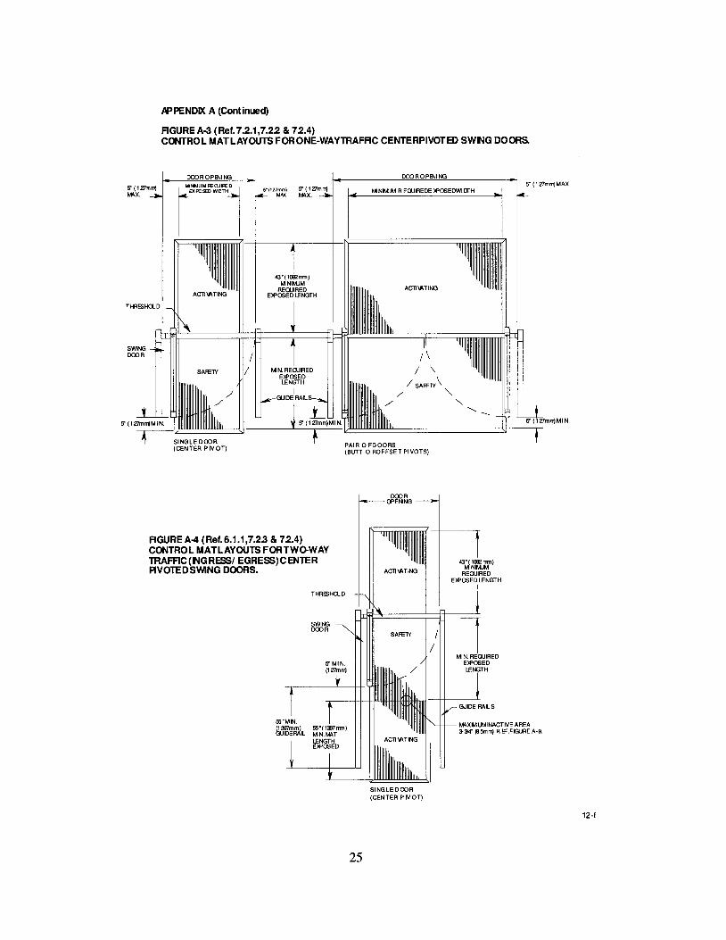
7.2.1 The width of the exposed area of an activating or safety control mat shall be the width of thedoor opening less a maximum of 5 in. measured from both sides for a total maximum of 10 in. (SeeFigures A-I, A-2, A-3, A-4, A-12A.)
7.2.2 A safety zone shall be provided by a safety control mat on the swing side of the door. Thelength of the exposed area shall extend a minimum of 5 in. beyond the lead edge of the door in the openposition. (See Figures A-I, A-2, A-3, A-4, A-12A.)
7.2.3 Swinging doors serving both egress and ingress, including non-knowing act double egressdoors, shall have a series of control mats on the swing side of the door(s) consisting of a safety controlmat nearest the opening with a length of exposed area a minimum of 5 in. beyond the lead edge of thedoor in the open position and one or more activating control mats totaling an additional 55 in. ofexposed length. (See Figure A-2 & A-4.)
7.2.4 The exposed length of the activating mat on the non swing side shall be a minimum of 43 in.(See Figures A-I, A-2, A-3, A-4.)
7.3 Sliding Doors
7.3.1 The width of the exposed area of an activating mat shall be the clear opening width less amaximum of 5 in. measured from both sides for a total maximum of 10 in. (See Figures A-5 & A-6.)
7.3.2 Sliding doors shall have an activating control mat with a minimum exposed length of 43 in.(See Figures A-5 & A-6.)
7.3.3 Sliding doors used for one way traffic shall be provided with a control mat that will hold thedoor open or return the door to the open position when approached by a person from the side notintended for approach. The activating length shall extend a minimum of 24 in. from the face of thedoor. The width of the control mat shall comply with 7.3.1. The control mat shall be deactivated whenthe door(s) is (are) within 6 in. of the fully closed position.
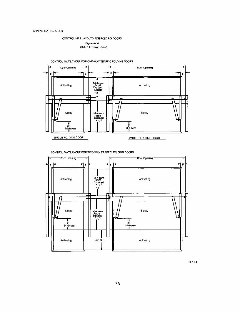
7.4 Folding Doors
7.4.1 The width of the exposed area of an activating or safety control mat shall be the width of thedoor opening less a maximum of 5 in. measuring from both sides for a total maximum of lain. (SeeFigure A-16.)
7.4.2 A safety zone shall be provided by a safety control mat on the fold side of the door. Thelength of the exposed area shall extend a minimum of 5 in. beyond the edge of the door in the openposition. (See Figure A-16.)
7.4.3 Folding doors serving both egress and ingress shall have a series of control mats on the foldside of the door(s) consisting of a safety control mat nearest the opening with a minimum of 5 in.beyond the edge of the FS panel in the open position, and one or more activating control mats totalingan additional 43 in. of exposed length. (See Figure A-16.)
7.4.4 The exposed length ofthe activating mat on the non fold side shall be a minimum of 43 in.
10
7.5 Joining of Control Mats
7.5.1 Control mats are permitted to be fitted side by side with the longest dimension perpendicularto the opening and shall not have an inactive area at the meeting line exceeding 2-112 in. (See FigureA-8.)
7.5.2 Control mats are permitted to be fitted side by side with the longest dimension parallel to thedoor opening and shall not have an inactive area at the meeting line exceeding 3-3/4 in. (See Figure A9.)
7.5.3 Control mats meeting at a threshold shall not have an inactive area exceeding 6 in. includingthreshold width. (See Figure A-7.)
7.5.4 The active area of a control mat shall be a maximum of 1-112 in. from any edge of theexposed area. (See Figure A-lO.)
7.6 Performance Requirements of Control Mats
7.6.1 A control mat circuit shall operate at 30 volts rms or less.
7.6.2 Control Mat Sensitivity Test
7.6.2.1 Circuit shall be activated when a solid steel test disc 2.26 in. in diameter is depressedwith a 25 lbf (110 N) applied vertically, perpendicular to the disc in accordance with 7.6.2.3 and7.6.2.4, except that if the circuit is not activated, a 30 lbf (130 N) shall be applied at the area of theelectrical contact connections and adjacent locations described in 7.6.2.3. Activation is achieved whenthe "off' state circuit resistance and capacitance, which must be greater than 5000 ohms and less than100 nanofarads, changes to an "on" state circuit resistance of less than 400 ohms.
7.6.2.2 The Control Mat shall be divided into 12 equal rectangles covering the active area,except when the length of the mat is such that the length of each rectangle would be greater than 12 in.then the mat shall be divided into 15 or 18 equal rectangles so that the length of each rectangle is notless than 8 in. nor more than 12 in.
7.6.2.3 The test disc shall be placed in the approximate center of each interior rectangle. Forperimeter rectangles, place the disc so that it abuts the edge of the active area 1-112 in. from theexposed edge of the mat at the approximate center line of the rectangle. Compensating for the weightof the disc, apply a force to activate the circuit and take a single reading. If the disc and force fail toactivate the Control Mat at any of the test locations, place the disc on adjacent 90 degree tangents to thetest location(s) within the active area of the mat. The disc shall activate the mat at all adjacentlocations. If a check on the initial reading is desired, a period of at least 10 minutes shall be allowedbetween readings. One test disc diameter shall be omitted from each comer of the mat when testing.The mats shall be tested on a flat, rigid surface.
7.6.2.4 The test shall be conducted at 68 degrees ± 5 degrees F (20 degrees ± 2 degrees C).Mats shall be placed in the test room not less than 4 hours prior to the test.
7.6.3 Control Mat Friction Test
7.6.3.1 A control mat shall have a coefficient of friction when dry and clean of not less than0.66 when tested in accordance with 7.6.3.
7.6.3.2 Coefficient of friction (M) shall be measured using a standard friction block (N) havinga diameter of 4 inches (100 mm), weighing 15 lbs. (7 kg) and equipped with a Neolite bottom 1/4 in.thick. The Neolite composition rubber shall have a smooth flat bottom surface without ridges andShore A hardness of 90 ±3. The sheen shall be removed from the Neolite surface prior to use. To
11
prepare the assembly surface prior to its initial use, place a sheet of 400 grit wet or dry silicon carbidepaper on a flat surface. Sand the Neolite material gently by moving the assembly back and forth fourtimes for a distance of about 4 in. Repeat at an angle of 90 degrees. This constitutes one cycle ofsurface preparation. This procedure is to be repeated for a total of 10 cycles.
7.6.3.3 The block shall be placed in the middle of the mat with a linear scale calibrated inpounds (kilograms) attached.
7.6.3.4 Force required to just begin to move the block in any direction shall be a minimum of a10 lbf (44 N) applied 1/2 in. from the bottom of the block.
7.6.3.5 The test shall be conducted in a room temperature of 68 degrees F ± 5 (20 degrees C ±2). Mats shall be placed in the test room not less than 4 hours prior to the test.
7.6.3.6 The formula used for determining the coefficient of friction (M) shall be M =F -:- Nwhere N =15 lb. (7 kg) weight (See 7.6.3.2) and F =10 lbf (44 N) minimum.
7.6.4 Control Mat Trim. Surface applied control mats shall be secured to the floor with trimhaving a tapered lead up a minimum of 4 times the mat thickness at the exposed edge. (See Figure A10.)
8. SENSORS
8.1 General Requirements for Sensors8.1.1 Activating zones for swinging, sliding and folding doors shall have a minimum width equal to
the width of the clear opening measured at 8 in. and 30 in. perpendicular from the face of the closeddoor(s). The length from the face of the door shall be 43 in. minimum measured at the center of theclear opening. Detection shall be effective to within 5 in. from the face of the door measured at thecenter of the clear opening. Exception: If the 43" activating zone length is not practical due to physicalor environmental conditions, it shall be permissible to be reduced to 30 inches, along with an additionalsign, visible from the side the zone has been reduced on, stating "AUTOMATIC CAUTION DOOR" asdescribed in 11.2.3.
8.1.2 Motion sensors shall detect a 28 in. minimum high person, moving at a rate of 6 in. persecond minimum toward the center of the door within the detection areas described.
8.1.3 Presence sensors shall detect a stationary 28 in. minimum high person within the detectionareas described for a minimum of 30 seconds.
8.2 Swinging Doors8.2.1 Swinging doors shall have an activating zone as defined in 8.1.1.
8.2.2 A safety zone shall be provided on the swing side of all power operated swinging doors.
8.2.2.1 If an overhead presence sensor(s) is used to provide a safety zone, the length of theactive area shall be effective to within 5 in. of the face of the closed door measured at the center of thedoor opening. The safety zone shall extend 5 in. minimum beyond the leading edge of the door in theopen position when measured at the center of the door opening. The width of the active area measuredperpendicular from the face of the closed door shall be the door opening less 5 in. maximum measuringboth sides for a total of 10 in. maximum measured parallel to the face of the door at a distance of 8 in.and 30 in. When the safety zone is occupied by a 28 in. minimum high person fully in the safety zoneof a fully open or closed door, the door operator shall not operate. (See Figure A-12A)
12
8.2.2.2 When an overhead presence sensor on the swing side is prevented from providing asafety signal to the control during the closing cycle, an additional sensor, sensors, or photo beam shallbe used on the swing side to
1) stop the door, or2) continue to close the door, or3) slow the reopening door to a maximum latch edge speed of 4 in. per second measuredwithin 1 in. of the latch edge before any contact is made.
8.2.2.2.1 When using a photo beam, the detection width shall be not less than the clearopening; the beam shall be located between 6 and 28 in. above the finish floor, and not more than 8 in.from the lead edge of the door panel in the full open position (See Figure A-12A).
8.2.2.2.2 When using a door mounted presence sensor, the detection area shall beeffective to within 5 in. from the face of the door, for one half of the width of the door, and to within 1in. of the lead edge, and shall detect a 28 in. minimum high person fully in the defined area. (SeeFigure A-12A).
8.2.2.3 If a door mounted presence sensor is used to provide a safety zone, it shall beeffective to within 5 in. from the face of the door for the width of the door less 5 in. from the pivotpoint and to within 1 in. of the lead edge. A door mounted sensor on either side of the door shall detecta 28 in. minimum high person fully in the swing path, during the opening or closing cycle and shallcause the door to reverse direction, stop or slow down to a maximum latch edge speed of 4 inches persecond measured within 1 in. of the latch edge before any contact is made. (See Figure A-12B&C)
8.2.3 Swinging doors serving both egress and ingress, including non-knowing act doubleegress doors, shall have on the swing side, a safety zone as defined in 8.2.2, and an activating zone.The length of the activating zone shall be established as follows: the activating zone starts adjacent tothe safety zone and extending an additional 55 in. from the leading edge of the door in the openposition. (See Figure A-12A&C&D tbd.) The activating zone shall have a minimum width equal to thewidth of the clear opening measured at 8 in. and 30 in. from the interface of the safety and activatingzones.
8.2.4 If a sensor is used for activating and a safety control mat is used as a safety zone, the exposedarea of the safety control mat shall extend 5 in. minimum beyond the edge of the door in the openposition and:1) extend 5 in. into the non swing side area of the door measured from the face of the door; or2) the door opening area shall be provided with a presence sensor which shall be used to prevent afully open door(s) from closing when a person is in the space between two non overlapping activatingor safety zones; or3) the door closing cycle shall have a delay of 4 seconds minimum after the activating zone is clear;or4) be equipped with a door mounted presence sensor on the non swing side as described in 8.2.2.2.
8.2.4.1 The width of a safety control mat shall be in accordance with 7.2.1. (See Figure A-12A)
8.2.5 When sensors are used to provide both an activating and a safety zone, if the distance betweenthe two non overlapping zones exceeds 8 in. the door system shall:1) be equipped with a safety control mat; or2) be equipped with a presence sensor across the door opening; or3) have a door closing cycle delay of 4 seconds minimum after the activating zone is clear; or4) be equipped with a door mounted presence sensor on the non swing side as described in 8.2.2.3.
13
8.3 Sliding Doors
8.3.1 Sliding doors shall have an activating zone as defined in 8.1.1.
8.3.2 A presence sensor shall be used to detect a person fully in the space between two nonoverlapping activating zones for the width of the clear opening as follows:
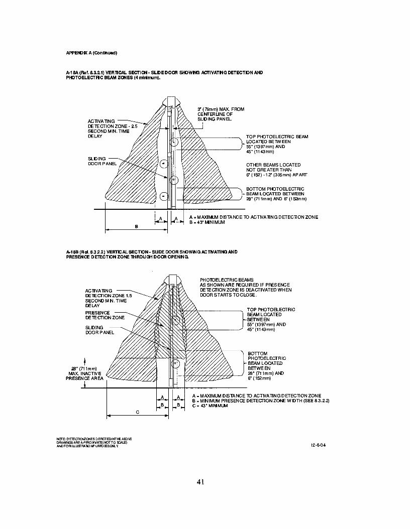
8.3.2.1 If photo electric beams are used (See Figure A-18A):(1) A minimum of four photo electric beams shall be installed, two minimum on each side of thesliding door. The beams' location shall alternate from side to side. The lowest beam shall be installed6 to 28 in. from the floor and the other three at a spacing between 6 and 12 in. apart with the top beamat 45-55 in. from the floor. The photo electric beam area of detection shall extend across the clear dooropening. (See Figure A-18A); and(2) The beams shall be installed within 3 in. from the centerline of the slide door; and(3) The beams shall remain active from fully open to within 6 in. of closed; and(4) The door shall remain fully open for 2.5 seconds minimum after loss of detection.
8.3.2.2 If an overhead presence sensor is used through the door opening it (See Figure A18B.):(1) Shall detect a 28 in. minimum high person and extend out a minimum of 5 in. from the face ofthe door on each side; and(2) The detection zone shall remain active from open to within 6 in. of closed, or shall have anoverhead presence sensor active area within 3 in. from the face of the door or, a minimum of two photoelectric beams on one side of the door, with the lower beam installed 6-28 in. and top beam 45-55 in.from the floor. (See Figure A-18B.)(3) If beams are required they shall be installed within 3 in. from the centerline of the slide door andremain active from fully open to within 6 in. of closed.(4) The door shall remain fully open for 1.5 seconds minimum after loss of detection.
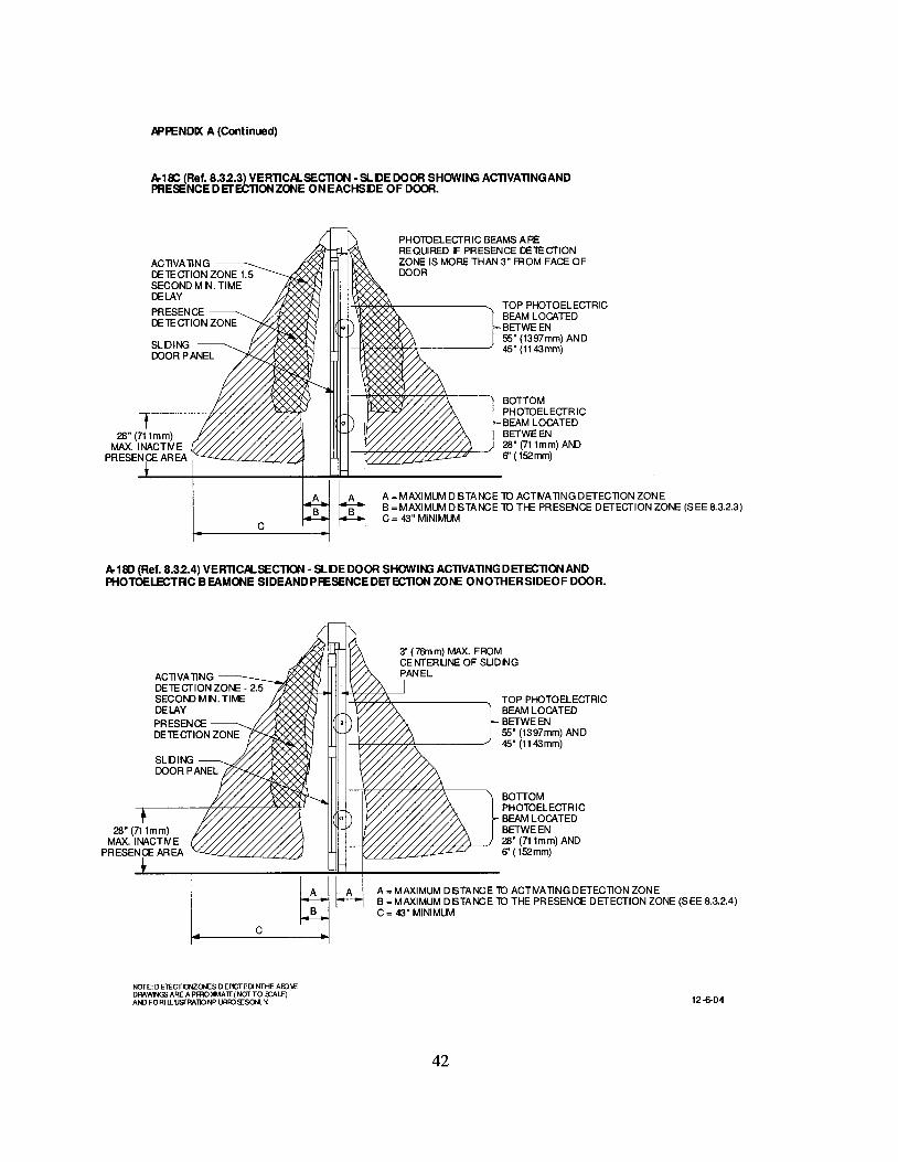
8.3.2.3 If overhead presence sensors are installed on each side of the sliding door opening (SeeFigure A-18C.):(1) They shall not have an inactive area more than 5 in. extending out from the face of the door. If theinactive area exceeds 3 in. from the face of the door, it shall have a minimum of two photo electricbeams on one side of the door, with the lower beam installed 6-28 in., and top beam 45-55 in. from thefloor; and(2) The detection zone shall remain active from open to within 6 in. of closed.(3) If beams are required they shall be installed within 3 in. from the centerline of the slide door andremain active from fully open to within 6 in. of closed.(4) The door shall remain fully open for 1.5 seconds minimum after loss of detection.
8.3.2.4 If photo electric beams are used on one side of the door and an overhead presence sensoris installed on the opposite side of the sliding door opening (See Figure A-18D):
(1) A minimum of two photo electric beams shall be installed on one side of the door with the lowerbeam installed 6-28 in. and top beam 45-55 in. from the floor; and
(2) The beams shall be installed within 3 in. from the centerline of the slide door; and(3) The overhead presence sensor installed on the side opposite the beams shall not have an inactive
area more than 5 in. extending out from the face of the door; and(4) The beams and overhead presence sensor must remain active from fully open to within 6 in. of
closed; and
14
(5) The door shall remain fully open for 2.5 seconds minimum after loss of detection.
8.3.3 Sliding doors used for one way traffic shall be provided with a secondary activating zone onthe side not intended for approach. The secondary activating zone shall extend a minimum of 24 in.from the face of the door and be effective to within 5 in. from the face of the door measured at thecenter of the door opening. The zone shall have a minimum width equal to the width of the clearopening measured at 8 inches perpendicular from the face of the closed door. The sensor shall bedeactivated when the door(s) is (are) within 6 in. of the fully closed position.
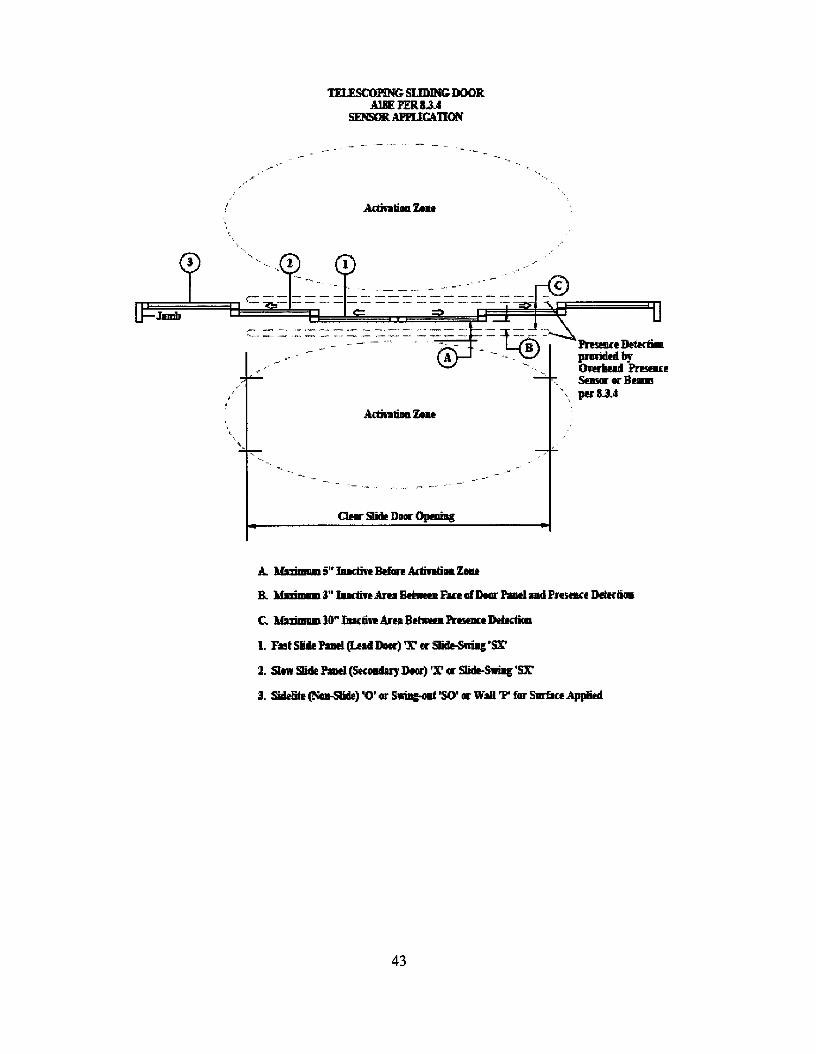
8.3.4 Telescoping Sliding Doors Activating sensors, overhead presence sensors, and beams aremeasured to the closest sliding panel on the side they are installed. If overhead presence sensors orbeams are used, they shall not have an inactive area more than three inches from the face of the closestsliding panel, and not create an inactive area greater than 10 inches between the two non overlappingzones, and shall comply with the methods listed in 8.3.2.1 through 8.3.3. If the inactive area betweenthe two non-overlapping zones exceeds 8 inches, the door shall remain fully open for 2.5 secondsminimum after loss of detection.
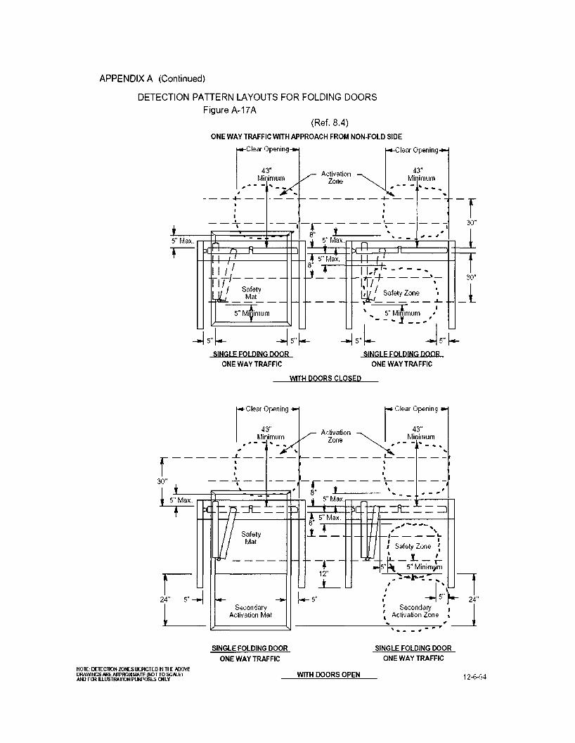
8.4 Folding Doors
8.4.1 Folding doors shall have an activating zone as defined in 8.1.1.
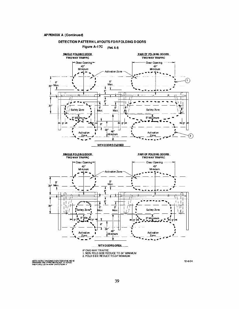
8.4.2 A safety zone shall be provided on the fold side of all power operated folding doors that shallextend 5 in. minimum beyond the edge of the FS panel measured when open. Detection shall beeffective to within 5 in. from the face of the door. The width of the safety zone when the door is closedshall be equal to the door opening less 5 in. maximum from both sides for a total of lOin. maximum.The width of the safety zone when the door is open shall be equal to the clear opening less 5 in.maximum from both sides for a total of 10 in. maximum measured 8 in. perpendicular to the door.When the safety zone is occupied by a 28 in. minimum high person fully in the safety zone of a fullyopen or closed door, the door operator shall not operate. (See figure A-17A, 17B, 17C & 17D.)
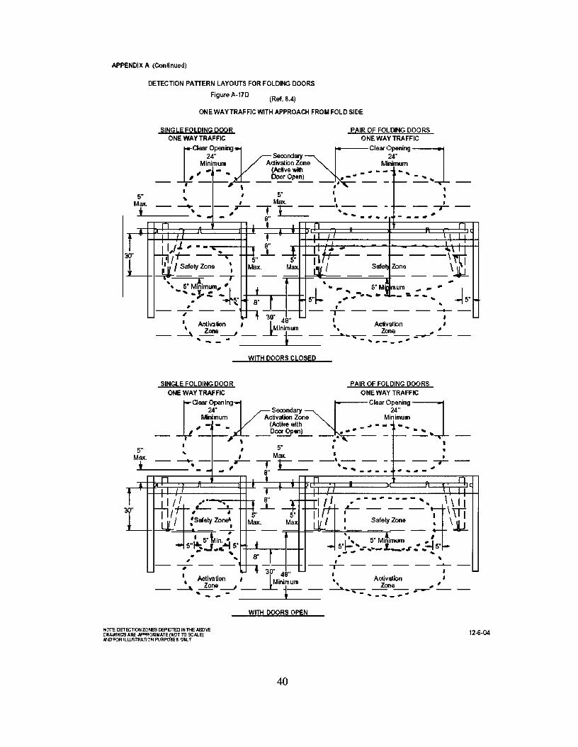
8.4.2.1 One way traffic doors with an intended approach from the fold side of the door shall havea secondary activating zone that extends a minimum of 24 in. on the non-fold side from the face of theclosed door and be effective within 5 in. from the face of the door measured at the center of the clearopening. The zone shall be deactivated when the door(s) is (are) within 6 in. or less of the fully closedposition. (See Figure A-17D.)
8.4.2.2 One way traffic doors with an intended approach from the fold side shall have anactivating zone on the fold side with a minimum width equal to the clear opening measured at 8 in. and30 in. from the outer edge of the safety zone and perpendicular to the face of the closed door. (SeeFigure A-17D.)
8.4.2.3 Folding doors for one way traffic with intended approach from the non-fold side shallhave, on the folding side of the door, both a safety zone as defined in 8.4.2 and a secondary activatingzone. The length of the secondary activating zone on the fold side shall be established as follows: Thezone starts adjacent to the safety zone and shall extend 24 in. beyond the edge of the FS panel whenopen. (See Figure A-17A&B.) The zone shall have a minimum width equal to the width of the clearopening measured at 8 in. from the outer edge of the safety zone and perpendicular to the face of theclosed door. The sensor shall be deactivated when the door(s) is (are) within 6 in. of the fully closedposition.
8.4.3 Folding doors serving both egress and ingress shall have, on the folding side of the door, both
15
a safety zone as defined in 8.4.2 and an activating zone. The length of the activating zone shall beestablished as follows: The activating zone (as defined in 8.4.1) starts adjacent to the safety zone andshall be effective to within 5 in. and shall extend 48 in. beyond the edge of the FS panel when open.(See Figure A-17C.) . The activating zone shall have a minimum width equal to the width of the clearopening measured at 8 in. and 30 in. from the outer edge of the safety zone and perpendicular to theface of the closed door.
8.4.4 When both activating and safety control mats are used in combination with sensors they shallbe in accordance with section 7.4. (See Figure A-l7A & A-17B)
8.4.5 If a sensor is used for activating and a safety control mat is used as a safety zone, the exposedarea of the safety control mat shall extend 5 in. minimum beyond the edge of the FS panel in the openposition and:1) extend 5 in. into the approach area of the door measured from the face of the door in the closedposition; or2) the door opening area shall be provided with a presence sensor which shall be used to prevent afully open door(s) from closing when a person is in the space between two non overlappingactivating/safety zone; or3) the door closing cycle shall have a delay of 4 seconds minimum after the activating zone is clear.(See Figure A-l7A & A-l7B.)
8.4.6 When sensors are used to provide both an activating and safety zones, if the distance betweenthe two non overlapping zones exceeds 8 in. the door system shall:1) be equipped with a safety control mat; or2) the door opening shall be equipped with a presence sensor across the door opening; or3) have a door closing cycle delay of 4 seconds minimum after the activating zone is clear. (SeeFigure A-17A & A-17B.)
9. KNOWING ACT DOOR ACTIVATION
9.1 Swinging (except double egress), Sliding, and Folding DoorsUse of a knowing act activating device which requires a knowing act to activate the automatic door,shall meet the following requirements:
9.1.1 Be installed in a location within view ofthe automatic door.9.1.2 Have an installation height of a minimum of 36 in. and a maximum of 48 in., or as specified
by the local building codes.9.1.3 Shallremain accessible from the swing or fold side when the door is opened and shall not be
located in a position where the user would be in the path of the moving door.9.1.4 The door shall remain fully open for a minimum time delay of five seconds after release of
the knowing act device. If located more than 12 feet from the center of the door, there shall be anadditional time delay of one second for each additional foot. For example, if the knowing act device islocated 14 feet from the door, the delay shall be seven seconds.
9.1.5 The door shall be equipped with safety zones, time delays, and guide rails as required in thisstandard for the type door and detection system selected.
9.1.6 Sliding and folding doors for one or two way traffic require a secondary activating zone oneach side the door extending a minimum of 24 in. from the face of the door and effective to within 5 in.from the face of the door measured at the center of the door opening. The secondary activating zoneshall have a minimum width equal to the clear door opening, and shall be deactivated when the door (s)is (are) within 6 in. of the fully closed position.
16
9.1.7 Swinging (except double egress), doors for one or two way traffic require the secondaryactivating zone only on the non swing side of the door. The secondary activating zone must remainactive while the door is closing and shall be deactivated within the last 10 degrees of closing. Also,one of the following requirements shall be met:
1) The secondary activating zone(s) shall extend a minimum of 24 in. from the face of the door andbe effective to within 5 in. from the face of the closed door measured at the center of the dooropening. The secondary activating zone shall have a minimum width equal to the clear dooropening, or2) Door mounted sensors complying with 8.2.2.3 are acceptable to be used as a secondaryactivating zone.
9.1.8 Swinging and folding door safety zones shall be active when the door (s) are closed and shallhave the same zone sizes as required for non-knowing act activation.
9.2 Double Egress Automatic Swing Doors The activating device shall meet the requirements of9.1.1 through 9.1.4.
9.2.1 One ofthe following safety zones is required:a. If an overhead presense sensor(s) is used to provide a safety zone, the length of the active
area shall be effective to within 5 in. of the face of the closed door measured at the center of thedoor opening. The safety zone shall extend 5 in. minimum beyond the leading edge of the doorin the open position when measured at the center of the door opening. Overhead mountedsensors shall provide a detection zone equal to the door panel width minus 5 in. from the pivotjamb and to within 5 in. of the lead edge of the door, measured at 8 and 30 in. parallel to thedoor face (A-19A).
b. Door mounted sensors shall meet 8.2.2.3. (A-19B)c. Mats The safety zone shall extend 5 in. minimum beyond the leading edge of the door in the
open position when measured at the center of the door opening. Mats shall provide a detectionzone equal to the door panel width minus 5 in. from the pivot jamb, and to within 5in. of thelead edge ofthe door. (A-19C)
9.2.2 The door shall be equipped with a secondary activating zone on the approach side of theswing door as it swings away from the user. (A-19A, A-19B, A-19C)
a. The secondary activating zone for sensors shall come to within 5 in. of the face of the doormeasured at the center of the door opening and shall extend a minimum 24 in. from the face ofthe door.
b. Door mounted sensors shall meet 8.2.2.3. (A-19B)c. When control mats are used they shall extend a minimum 24 in. from the face of the door.d. The width of the secondary activating zone shall be equal to the width of the door panel less
5 in. from each side in the closed position.e. The secondary activating zone must remain active while the door is closing and shall be
deactivated within the last 10 degrees of closing.
9.2.3 The doors shall be simultaneously activated.
17
10. ENTRAPMENT PROTECTION
10.1 Sliding Doors10.1.1 A sliding door shall be adjusted so that the closing speed is one foot per second maximum
per leaf to latch check for doors weighing up to and including 160 lbs (71 kg):For doors weighing more than 160 lbs (71 kg):
V = .J161/W where:V =Velocity in ft/secW =Weight of Door in lbs
10.1.2 Latch check shall occur for sliding doors at no less than 2 in. from the closed position ofeach sliding door leaf.
10.1.3 A stopped sliding door shall not require more than 30 lbf (133 N), measured at the leadingedge, to prevent it from closing at any point in the closing cycle.
10.1.4 Sliding doors provided with a break away device shall require no more than a 50 lbf (222 N)applied 1 inch (25 mm) from the leading edge of the lock stile for the break out panel to open. Breakaway devices (swinging panels) for doors that slide on the egress side of an opening shall be equippedwith a self closing device or interrupt automatic operation when used in the break out mode. Breakaway devices incorporating swing out sidelites shall interrupt automatic operation when used in thebreak out mode.
10.1.5 Sliding doors utilizing sensors or control mats shall remain fully open a minimum of 1.5seconds after loss of detection, unless otherwise specified within this standard.
10.2 Swinging Doors10.2.1 The opening time of a swing door to 80 degrees shall not be less than 1.5 seconds.
10.2.2 The force required to prevent a stopped power operated swinging door in the last 10 degreesof opening from moving in the direction of opening shall not exceed 30 lbf (133 N) measured 1 in.from the lock edge of the door.
10.2.3 Back check shall occur at no less than 10 degrees of full open position.
10.2.4 Swing doors utilizing sensors or control mats shall remain open a minimum of 1.5 secondsafter loss of detection unless otherwise specified within this standard.
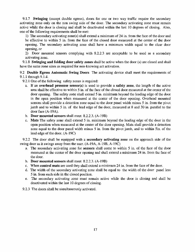
10.2.5 A swinging door shall be adjusted so that closing times to latch check shall be the minimumvalues in the following table:
(D) Inches 36 & under 36 42 42 48 48(W) Pounds (kg) to 100 (45) to 140 (64) to 110 (50) to 150 (68) to 120 (55) to 160 (73)(T) Seconds 2.0 2.3 2.3 2.7 2.8 3.2
For doors of other weights and widths:
T = D.JW /188 where:W =Weight of door in poundsD = Width of door in inchesT =Closing time to latch check in seconds
10.2.6 Latch check shall occur for swinging door at no less than 10 degrees from closed positionand the door shall not close through the final 10 degrees in less than 1.5 seconds.
10.2.7 The force required to prevent a stopped power operated swinging door from moving in the
18
direction of closing shall not exceed a 30 Ibf (133 N) measured 1 in. from the lock edge of the door atany point in the closing cycle.
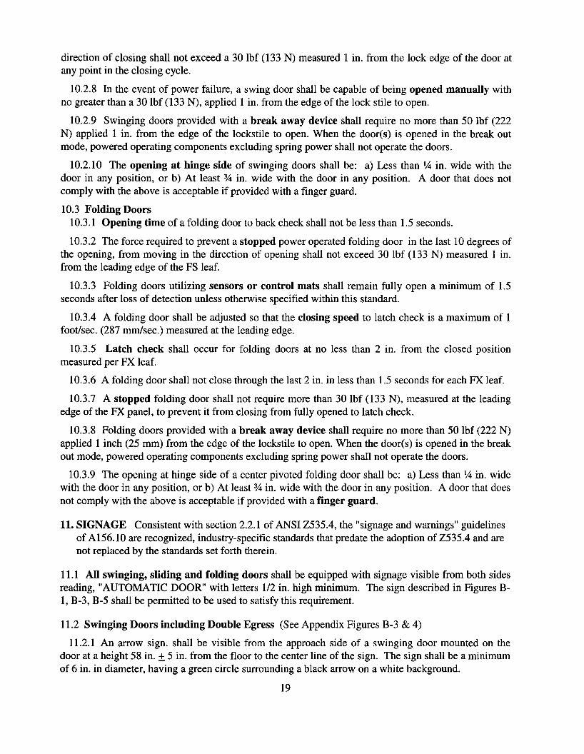
10.2.8 In the event of power failure, a swing door shall be capable of being opened manually withno greater than a 30 lbf (133 N), applied 1 in. from the edge of the lock stile to open.
10.2.9 Swinging doors provided with a break away device shall require no more than 50 lbf (222N) applied 1 in. from the edge of the lockstile to open. When the door(s) is opened in the break outmode, powered operating components excluding spring power shall not operate the doors.
10.2.10 The opening at hinge side of swinging doors shall be: a) Less than 1,4 in. wide with thedoor in any position, or b) At least % in. wide with the door in any position. A door that does notcomply with the above is acceptable if provided with a finger guard.
10.3 Folding Doors10.3.1 Opening time of a folding door to back check shall not be less than 1.5 seconds.
10.3.2 The force required to prevent a stopped power operated folding door in the last 10 degrees ofthe opening, from moving in the direction of opening shall not exceed 30 Ibf (133 N) measured 1 in.from the leading edge of the FS leaf.
10.3.3 Folding doors utilizing sensors or control mats shall remain fully open a minimum of 1.5seconds after loss of detection unless otherwise specified within this standard.
10.3.4 A folding door shall be adjusted so that the closing speed to latch check is a maximum of 1foot/sec. (287 mm/sec.) measured at the leading edge.
10.3.5 Latch check shall occur for folding doors at no less than 2 in. from the closed positionmeasured per FX leaf.
10.3.6 A folding door shall not close through the last 2 in. in less than 1.5 seconds for each FX leaf.
10.3.7 A stopped folding door shall not require more than 30 Ibf (133 N), measured at the leadingedge of the FX panel, to prevent it from closing from fully opened to latch check.
10.3.8 Folding doors provided with a break away device shall require no more than 50 Ibf (222 N)applied 1 inch (25 mm) from the edge of the lockstile to open. When the door(s) is opened in the breakout mode, powered operating components excluding spring power shall not operate the doors.
10.3.9 The opening at hinge side of a center pivoted folding door shall be: a) Less than 1,4 in. widewith the door in any position, or b) At least % in. wide with the door in any position. A door that doesnot comply with the above is acceptable if provided with a finger guard.
11. SIGNAGE Consistent with section 2.2.1 of ANSI Z535.4, the "signage and warnings" guidelinesof A156.10 are recognized, industry-specific standards that predate the adoption of Z535.4 and arenot replaced by the standards set forth therein.
11.1 All swinging, sliding and folding doors shall be equipped with signage visible from both sidesreading, "AUTOMATIC DOOR" with letters 1/2 in. high minimum. The sign described in Figures B1, B-3, B-5 shall be permitted to be used to satisfy this requirement.
11.2 Swinging Doors including Double Egress (See Appendix Figures B-3 & 4)
11.2.1 An arrow sign. shall be visible from the approach side of a swinging door mounted on thedoor at a height 58 in. ± 5 in. from the floor to the center line of the sign. The sign shall be a minimumof 6 in. in diameter, having a green circle surrounding a black arrow on a white background.
19

11.2.2 An international "DO NOT ENTER" sign shall be visible from the side of doors that swingstowards pedestrians attempting to travel in the wrong direction mounted on the door at a height 58 in. ±5 in. from the floor to the center line of the sign. The sign shall be a minimum of 6 in. in diameter,having a red circle with the wording, "DO NOT ENTER", in the red circle.
11.2.3 Swinging doors serving both egress and ingress shall be marked with a decal, visible from theswing side of the door, with the words "AUTOMATIC CAUTION DOOR". The sign shall bemounted on the door at a height 58 in. ± 5 in. from the floor to the center line of the sign. The signshall be a minimum of 6 in. in diameter and with black lettering on a yellow background.
11.3 Sliding Doors (See Appendix Figures B-1 & 2)
11.3.1 Sliding doors with swinging leaves shall be provided with signs reading, "IN EMERGENCYPUSH TO OPEN". The signs shall have red backgrounds with contrasting letters 1 in. high minimum.The signs shall read horizontally and be located adjacent to the lock stile on a center line 36 in.minimum and 60 in. maximum from the floor applied to the side appropriate for egress.
11.3.2 Sliding doors that slide alongside an adjacent sidelite or wall shall be equipped with a signthat instructs users to stand clear of the sliding door travel path. The letters shall be 1 in. high minimumon contrasting background and located at 36 to 60 inches from the floor.
11.4 Folding Doors (See Appendix Figures B-5 & 6)
11.4.1 For one way traffic folding doors, an arrow sign, shall be visible from the approach side of afolding door mounted on the door at a height 58 in. ± 5 in. from the floor to the center line of the signon the FX panel. The sign shall conform to the sign described in paragraph 11.2.1. On the nonapproach side the international "DO NOT ENTER" sign as described in paragraph 11.2.2 shall bevisible. If folding doors are being used in pairs, each FX panel is required to have signs.
11.4.2 Folding doors serving both egress and ingress shall be marked with an arrow sign asdescribed in paragraph 11.2.1, visible from the non fold side and the fold side shall be marked with the"AUTOMATIC CAUTION DOOR" sign as described in paragraph 11.2.3.
11.4.3 Folding doors shall be provided with signs as described in paragraph 11.3.1, mounted on theFX panel applied to the side appropriate for egress and a "DO NOT ENTER" sign as described inparagraph 11.2.2 shall be applied to the appropriate sides of the FX panel as determined by trafficflow.
11.5 Knowing Act Doors (See Appendix Figures B-1 & 3 & 5)
11.5.1 The door shall have signage which says "Automatic Door" along with other required signagevisible from each side of the door. In addition the door shall have signage which says "Activate Switchto Operate" on the side of the door having the Knowing Act switch. Each sign in Y2" high minimumletters.
12 BREAK AWAY EGRESS TEST FOR SWINGING, FOLDING AND SLIDING DOORS.
12.1 Cycle Test Doors with power operators shall be installed in a simulated wall and door framingassembly of sufficient strength to withstand all forces required by the tests. Installation shall be inaccordance with manufacturer's printed instructions. Maintenance and repair of other than break awayequipment is permitted to be performed during the testing cycles.
12.1.1 The test specimen shall be of the largest door size to be listed by the manufacturer.
12.1.2 Cycle for 300,000 cycles at a rate of 5 to 8 per minute.
20
12.1.3 Break away devices shall not be lubricated or adjusted during the test.
12.1.4 At every 50,000 cycles during the test, the doors shall undergo 1,000 break out cycles. At theconclusion ofthe test, break out forces shall not exceed those listed in 10.1.4, 10.2.9, and 10.3.8.
12.2 Salt Spray Test
12.2.1 A sample of the latching and hinge assembly of the break away device of a power operateddoor contained in an approximately 25 in. wide panel shall be subjected to a salt fog test in accordancewith ANSJlBHMA A156.18-2006 for Materials and Finishes for 168 hours.
12.2.2 Record the release force prior to conducting the test. This shall not exceed 50 lbf (222 N).12.2.3 At the conclusion of the exposure time, remove the sample and allow to dry for 24 hours
without cleaning.12.2.4 Then cycle the sample 10 times. The release force for the first cycle shall not exceed a 100
lbf (445 N). Release forces for the next 9 cycles shall not exceed 50 lbf (222 N).
21
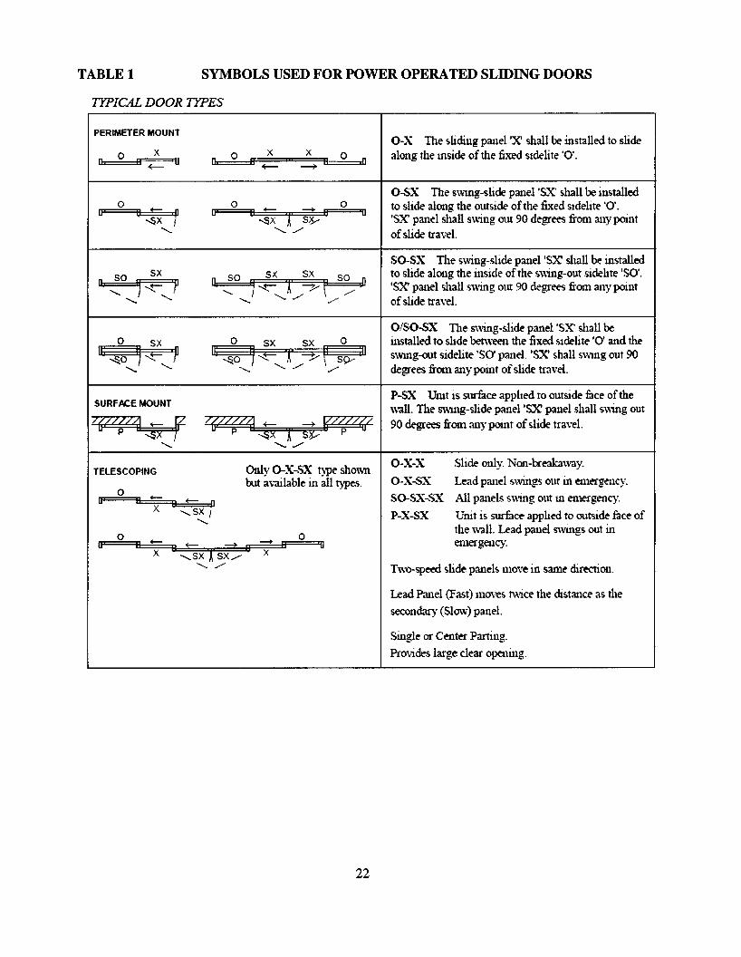
TABLE 1 SYMBOLS USED FOR POWER OPERATED SLIDING DOORS
TYPIC4L DOOR TYPES
PERIMETER MOUNT
0 X 0 X X~n
-E-- U n Ff -E-- ---4II
0 0 - --+0
U ., t= f u I.(
II U-.,sx -.,sx Sy
"' "' .,/
o-x TIle sliding panel 'X' shall be installed to slidealong the inside ofthe fixed sldelite '0'.
o-sx TIle S\ving-slide panel 's.X' shall be installedto slide along the outside ofthe fixed sldelite '0'.'SX' panel shall swing out 90 degrees from any pointofslide travel.
so sx
o 5XII:~
"' "'SURFN:.E MOUNT
qz~
"'
so 5X SX soOJ i--t- X ~r n
so-SX The swing-slide panel 'SX' shall be installedto slide along the inside ofthe swing-out sidelite 'SO'.'SX' panel shall Sv.ing out 90 degrees frOIll any pointofslide travel.
O/SO-SX The swing-slide panel 'SX' shall beinstalled to slide between the fixed sidelite '0' and theSWl11g-out sidelite 'SO' panel. 'SX' shall S'Wl11g out 90degrees from anypoult ofslide travel.
P-SX Unit is surface applied to outside face of thewall. The swing-slide panel'SX' panel shall swing out90 degrees from any poult of slide tra\'el.
Two-speed slide panels move in S3111e direction.
TELESCOPING
0~U IX
0~U IX
Only O-X-SX t)T!e shO\\nbut available 111 all types.
ou
O-X-X
O-X-SX
SO-SX-SX
P-X-SX
Slide only. Non-breabway.
Lead panel s'wings out in emergency.
All panels swing out Ul emergency.
Unit is surface applied to outside face ofthe wall. Lead panel swings out inen1e£gency.
22
Lead Panel (Fast) moves t'Wice the distance as the
secondary (Slow) panel.
Single. or Center Parting.
Provides large clear opening.

onvert me es to mm mu tlPly ,,,
Door Min. Width Activating Safety Mat Safety MatOpening Size Required Side - Min. Min. Length Min. Length
in. in. Length 3 in. Threshold lin. Thresholdin. m. in.
36 26 43 36 % 37 %37 27 43 36 % 37 % CENTER42 32 43 42 % 43 % PIVOT43 33 43 42 % 43 % SINGLES44 34 43 44 % 45 %45 35 43 44% 45 %48 38 43 48 % 49 %49 39 43 48 % 49 %
48 38 43 24 % 25 % CENTER50 40 43 24 % 25 % PIVOT60 50 43 30 % 31 % PAIRS62 52 43 30 % 31 %72 62 43 36 % 37 %74 64 43 36 % 37 %84 74 43 42 % 43 %86 76 43 42 % 43 %
36 26 43 41 % 41 % BUTTHINGE &
42 32 43 47 % 47 % OFFSET44 34 43 49 % 49 % PIVOTS48 38 43 53 % 53 % (SINGLE)
48 38 43 29 % 29 % BUTTHINGE &
60 50 43 35 % 35 % OFFSET72 62 43 41 % 41 % PIVOTS84 74 43 47 % 47 % (PAIRS)
TABLE I-A MINIMUM EXPOSED MAT SIZES FOR SWINGING DOORS (See 7.2)To c . hI' 1 b 25 4
23
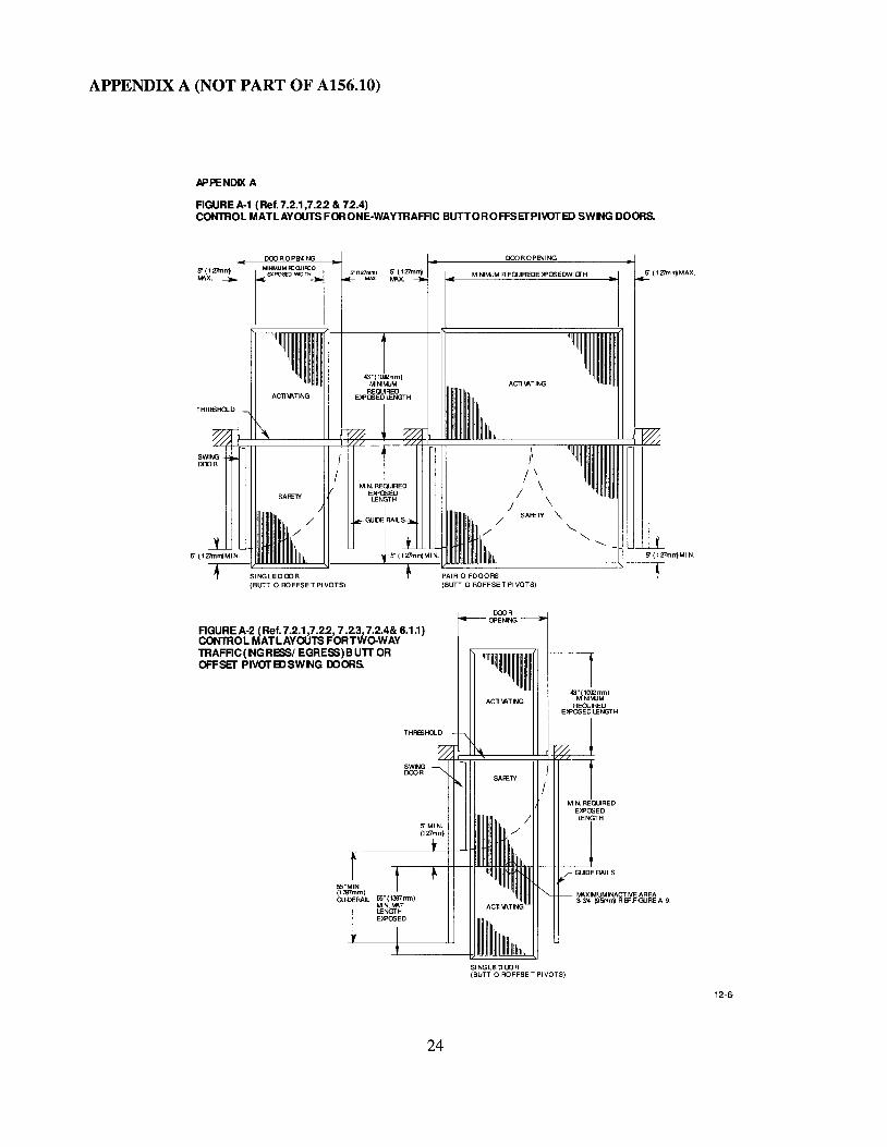
APPENDIX A (NOT PART OF A156.10)
APPENDD< A
AGUREA-1 (Ref. 7.2.1,7.22 & 72.4)CONTROL MATLAYOUTS FORONE-WAYTRAFAC BUTTOROFFSETPIVOTED SWNG DOORS.
DOOROPINING DCX)ROP8'JING
5"(127mn1MAx'
ACll\AT1NG
,\/ \
/ \/ \
/ SAFElY "-
/' "-'-..
----- -LIU...l.J....L
M NIMJM R EOOIREDE )f'OSEDWI crH5"(127mm) 5" (127mrrtMAX. Ml\x.r'NMU"~WI~1I ••__• I
S' (127m",MIN.
~IJJIJIIJJ~IJJIJIIJJU:::~J------....:...r....:...-llIJpA~,R~OIJJlJllJJFD~O~O~RS1J:==========!,,]---r
(BUTT 0 ROFFSE T PI VOTS)
S' (127m",....x.
THREl)HQ.O
AGUREA-2 (Ref. 7.2.1,7.22,7.2.3,7.2.4& 6.1.1)CONTROL MATLAYOUTS FOR TWO-WAYTRAFAC(NGRESSI EGRESS)BUTTOROFFSET PIVOTEDSWNG DOORS.
SWINGDOOR
G.)IDERAllS
M\XIMUMINACTIVEAREA3-3'4" 195m", REF.FIGUREA-'
SINGLE DOOR(BUTT 0 ROFFSE T PIVOTS)
12·6-
24
APPENDIX A (Continued)
RGUREA-3 (Ref.7.2.1,7.22 & 72.4)CONTROL MATLAYOUTS FORONE-WAYTRAFRC CENTERPIVOTB> SWNG DOORS.
S (l27mlTjMIIX.
THRESHO-D
DOOR OPENI NG
SINGLE DOOR(CENTER PIVOT)
S" (127mm) 5" (1 Zlm n1MAX ~X.
DOOROPENINGS (127mrrjMAX.
M NIMJM R EQUIREDE lPOSEDWI DrH
ACll'ATING
I/ \
/ "/ SAf£1Y"
/ "/' "
S(l27mrrjMIN.
DOOROPENING
RGUREA-4 (Ref. 6.1.1,7.23 & 72.4)CONTROL MATLAYOUTS FORTWo-WAYTRAFRC(NGRESSI EGRESS)CENTERPIVOTED SWING DOORS.
THRESHa..D
SWINGDOOR
25
MIIXIMUMINACTIVE AREA3-:Y4" (95mrrj R 8'.FIGURE A-S.
SINGLE DOOR(CENTER P IVOTI
12-(

" (127mm)
CLEAR OPENIWIDT
MINIMUM
~~~~~I WIDT I
43" (1092mm) MIN.ACTIVATIN REQUIRED (f)
EXPosr LENG1fi
'-------"SINGLE SLIDE DOOR
5" (127m
II PANICII BREAKAWAYI
~
t43" (1092mm) MIN.
REQUIRED tM
~~~~~~~~====~il EXPOT LENG
LJ --1
APPENDIX A (Continued)
FIGURE A-S (Ref. 7.3.1 and 7.3.2)CONTROL MAT LAYOUTS FORSINGLE SLIDE DOORS.
12-6-04
ACTIVATING
CLEAR OPENING I~---WIDTH-----
I---MINIMUM REQU~ 15" (127mm)I EXPOSED WID I -
II PANICII BREAKAWAY
~.
r43" (1092mm) MJN.
REQUIRED ~)
EXPosr LENGTH
~~~~~~=~~~~~~
I -11 43" (10~2mm) MIN.
II REQUIRED WEXPosr LENGTH
~~~::===::'==:=========:=:=?--------BI-PARTING SLIDE DOOR
CD SEE 7.3.3 FOR ONE-WAY TRAFFICEXPOSED LENGTH IS 24" MINIMUM
5" (127mm
FIGURE A-6 (Ref. 7.3.1 and 7.3.2)CONTROL MAT LAYOUTS FORBIPARTING SLIDE DOORS.
26
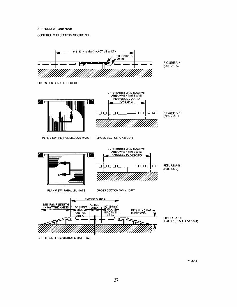
APP8'JDIX A (CClltimsd)
CONTRa... MATSCROSS SECTIONS.
6" 152mm MAX. INACTIVE WIDTH
CROSS SECTON atTHRESHOLD
2-1/Z' (64mm) MAX. NACTIVEAREA WHEN MATS ARE
PERPENDICULAR mOPENNG
FIGUREA-7(Ref. 7.5.3)
FIGUREA-8(Ref. 7.5.1)
PLAN VIEW- PERPENDICULAR MATS
PLAN VIEW- PARALLEL MATS
CROSS SECTON A-A at JONT
3-3/4" (95mm) MAX. NACTIVEAREA WHEN MATS AREPARALLEL TO OPENING
CROSS SECTON B-B at JONT
FIGUREA-9(Ref. 7.5.2)
EXPOSE D ARE A
MIN. RAMP LENGTH ACllVE4x MATTHICKNESS 1-1/2' (38mm)
....1-----........ MAX. ~""'R~14INACTIVE
CROSS SECTON atSURFACE MAT TRIM
27
1/2" (13mm) MAT 1THICKNESS
FIGUREA-10(Ref. 7.1, 7.5.4, and 7.6.4)
11-1-04
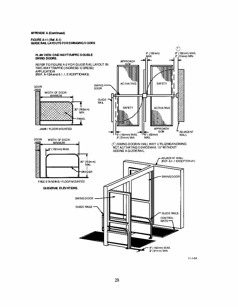
APPENDD< A (Continued)
FIGURE A·11 (Ref.6.1)GUIDE RAL LAYOUTS FORSVVlNGING DOORS
PLAN VIEW-ONE·WAYTRAFAC DOUBLESWIN3 DOORS.
REFER TOFIGUREA-2 FOR GUIDERAILLAYOUT INTWO-WAY TRAFF IC (INGRESSI EGRESS)APPLICATON(REF. A-12Aand 6.1.1, EXCEPrON#2).
Q)6" (l52mm) MAX.Z' (51mm) MIN.
ACTIVATING
6" (l52mm)MAX.
b APPROACHSIDE
6" (l52mm)MAX.
APPROACH
ACTIVATING
(f) SWING DOOR IN HALLWAY UTILIZING KNOWING)l;tT ACTIVATING DEVICEMAX 10"WITHOUTADDII'{J A GUIDE RAIL
GUIDERAL
SWINGDOOR
~" (762mm)MIN.
IDIVIDER
~"(762mm)
MIN.I
PANEL
1::' (l52mm) MAX.
WIDTH a= DOORMINIMUM
GUIDERAL ELEVATDNS.
FREE STANDNGI FLOOR MOJNTED
JAMB I FLOOR MOJNTED
DOOR WIDTH a= DOOR-J MINIMUM
SWING DOOR __.l-f+t--
11-1-04
28
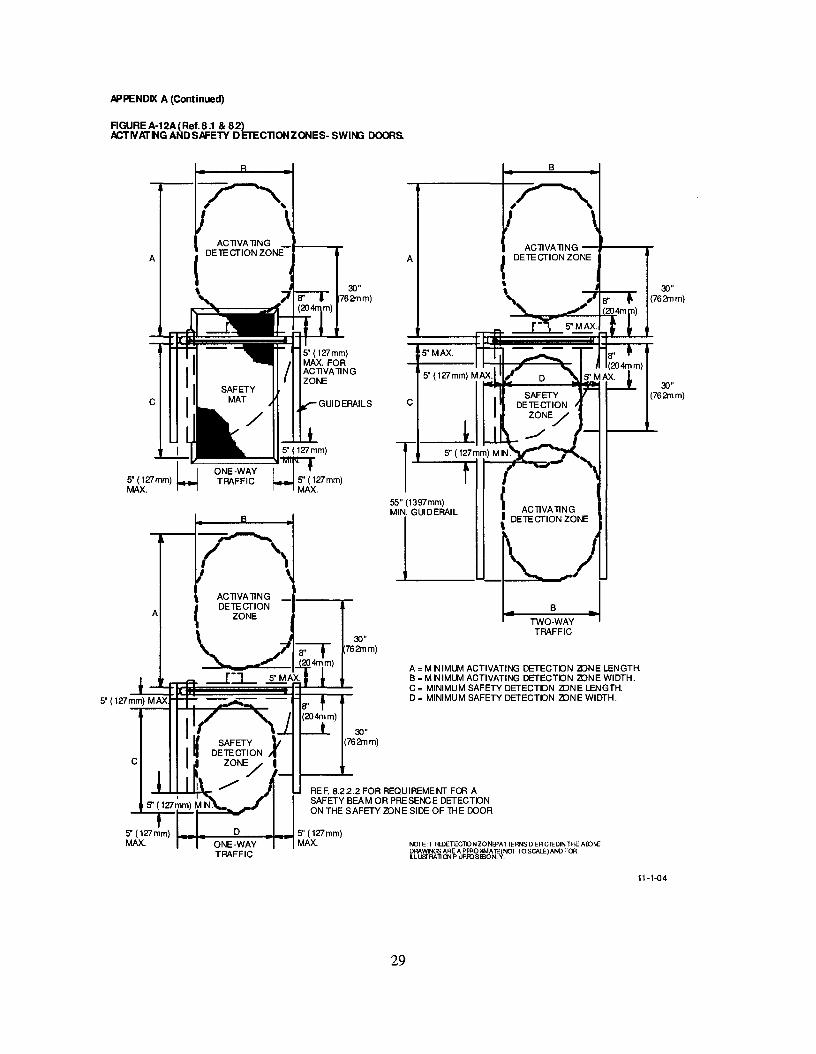
APPENDIX A (Continued)
F1GUREA-12A(Ref.8.1 & 82)ACT IIfAT NG AND SAFETY DErECllONZONES-SWING DOORS,
B
REF. 8.22.2 FOR REQUIREMENT Fffi ASAFETY BEAM OR PRESENCE DETECTONON THE SAFETY 2DN E SIDE OF lH E DOOR
30"(762mm)
30"(762mm)
TWO·WAYTRAFFIC
B
ACllVA liNG --J---.....DETECTION ZONE
A =MNIMUM ACTIVATING DETECTON 2DNE LENGTH.B =MNIMUM ACTIVATING DETECTON 2DNE WIDTH.C = MINIMUM SAFETY DETECTON 2DNE LENGTH.D = MINIMUM SAFETY DETECTON 2DNE WIDTH.
A
5"MAX.
C
T-55" (1397mm)
~c
30"762mm)
30"(762mm)
30"762mm)
ACllVAliNG -t---r( DETECTION ZONEA
A
C
C
5" (127mm) 1-~__~D::""_-fo-l5"(127mm)MAX. ONE.WAY MAX.
TRAFFICNOTE: T HBJETECllONZONfPATTERNS 0 ER ClEDINTHE AED\E
ilL~m~'1.t~rm~6'~~NOTTOSCAlE)ANDFOR
11·1·04
29
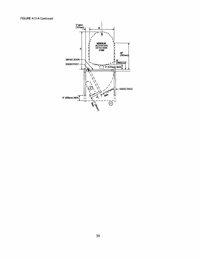
FIGURE A12-A Continued
5" MAX.(127mm)
I61
- ---;;;' -f'"I -,, ', ..I '
I '\
' ... j"" 7'< - ' (204mm)L_J 5" (127mm) MAX.
A
SWINGOOOR
OOORPIVOT
MINIMUMACTIVATINGDETECTION
ZONE
I,I\ 30"I (762nvn)
'8"
\\ I\\ /
r, \\ /\~ \\ /\0\ \\ /
~/ ,,1«\«\'
~~\.,,\"
8" (203mm) MAX.D' -\ '(~.11.#\ "r------- II
~~. - r.-\LJ"-~ \.!J. ~
~
30
GUIDE RAILS
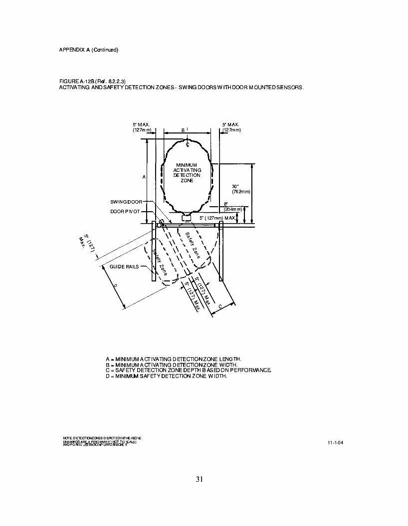
APPENDIX A (Cootimsd)
FIG URE A-12B (Ref. a2.2.3)ACTIVATING ANDSAFETYDETECTION ZONES- SWING DOORSW ITH DOOR MOUNTEDSENSORS.
5"MAX.(127mm
A
SWINGDOOR
DOOR P IVOT
MINIMUMACllVAllNGDElECTION
ZONE30"(762mm)
I, , 8"
\.... J - (204mm)e S' (127mm) MAX.
A = MINIMUM AcrlVATING DETECTIONZONE LENGTH.B = MINIMUM AcrlVATING DETECTIONZONE WIDTH.C = SAFETY DETECTION ZONE DEPTH BASEDON PERFORMANCED = MINIMUM SAFETY DETECTION ZONE WIDTH.
31
11-1-04

APPENDIX A (Cmtim.ed)
FIGUREA-12C (Ref. 8.2.3)ACTIVATING ANDSAFETVDETECTION ZONES- SWING DOORSW ITHDOOR MOUNTEDSENSORSTWO-WAYTRAFFIC.
A
SWING DOOR
DOOR PIVOT
~~
'" "::>~ ~./
GUIDE RAILS
T55" (1397mm)MIN. GUIDERAIL
LI ACllVA llNGI DElECTION ZONEI
B
TWO-WAYTRAFFIC
5"MAX.(127mm)
30"(762mm)
A = MINIMUMAcrlVATING DETECTION ZONE LENGTH.B = MINIMUMAcrlVATING DETECTION ZONE WIDTH.
SEE FIGUFE A-12B FOR SAFETYZONEDIMENSIONS.
NOTE: 0 ETECTIGlZO'lES 0 EACTEDI NTHE AlDIEDRAWlNGSARE APFR014MATE(NOf TO s::AL.EIAND FORI LLUsrRAllONP URfO~Sor-Ly.
32
11-1-04
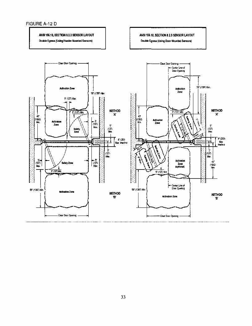
FIGURE A-12 D
ANSI 1&6.10, SECTION 8.2.3 SENSOR LAYOUT
Dollble Egrll5s(Using Huder Mounled Sensotsl
ANSI 156.10, SECTION 8,2.3 SENSOR LAYOUT
Double EgIS" (Using Door Moooted 5enSOlS)
METHOD'A'
METHOD'B'
56' (1m~ Mln~
Il'(:<m)lAin
__-+"""'I-+-+.L..lnilClive
I
I-Get'lIef UneCl000< Opering
ActIvIUon ZOOt
1---CleM DooI Op.nlllg
8"(Il3)Millt InaeIlVe
METHOD'B'
METHOO'I(
-----~--------~..~-~-~~~-~--~-~-_ .._-~---~~
33
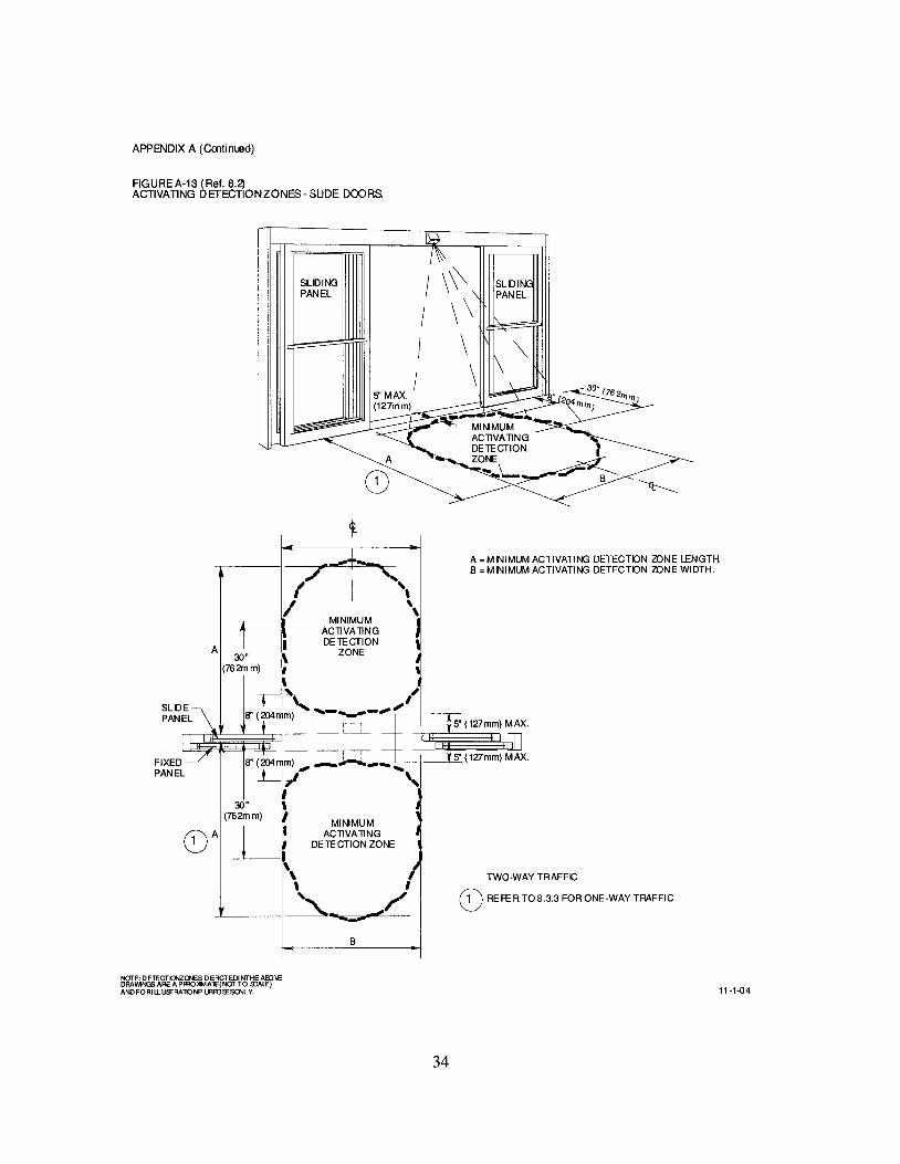
APPENDIX A (Cmtimed)
FIGUREA-13 (Ref. 8.2)ACTIVATING DETECTIONZONES- SUDE DOORS.
MINIMUMACllVAllNGDE1£CTION
ZONE ~
... >-..~- B:::::A
I \\0I \ \JI~~III \I \
5" MAX.(127mm)
SLIDINGPANEL
A
FIXEDPANEL
A = MINIMUM ACTIVATING DETECTON 20NE LENGTH.B=MINIMUMACTIVATING DETECTON 2ONEWIDTH.
"\MINIMUMACllVAllNGDE1£CTION
ZONE
r-, 5' (127mm) MAX.--'--'-
-r--,- - ;08" (204mm) _ ....;,'....'......-.,J-_I__~5n (127mm) MAX.
1-,1" "
(0A
MINIMUMACllVAllNG
DE 1£ CTION ZONE
TWO·WAY TRAFFIC
(0 REFER T08.3.3 FOR ONE·WAY TRAFFIC
B
NOTE: D ElECTIO>IZCNES DEACTEDI NTHE ABJIEDRAWINGS ARE A PFRO~AlE(NOT TO s::ALE)ANDFORI LLusrRATlONP URRJlESQNL~ 11-1-04
34
AP PEND D( A (Continued I
FOLDING DOORSPANELLAYOUT
Figure A·14
(Ref. 5.0)
SING LE FOLDING DOOR
FS
PAIROF FO LD NG DOORS
FS= FOLD SVY'ING PANEL
FX= FOLD SLIDE PANEL
FS
GUIDE RAL LA YO UTS FO R FO LDING DOORS
FigureA-15(Ref. 6.2)
SINGLE FOLDING DOOR
Glll:le Rail
PAIRO F FO LDING DOORS
e 11"'Ili It J
[or II ~ lnlm'A'
II~Ii" 1Ii11lmlm
,'"
-J
11//!Ju-l
FfA'Uillmim
or II II InlmJ
Ii" lIallmlm
"A"=12 i nches,(3J5mm)Daar Jam b
Palel arDIIICle r
t.'I===~-,-
3 '1111.
Pan I arDillcl! r
3 ' 1111.
JAIIB AND FLOO R 110 UN TE D FREESlJ' NDNG FLOOR 110 UNTED
ll-HU
35
APPENDIX A (Continued)
CONTFOL MAT LAYOUTS FOR FOLDING DOORS
FigureA-16
(Ref. 7.4 through 7.4.4.)
CONTFOL MATLAYOUT FOR ONE- WAY TRAFFIC FOLDING DOORS
-DoorOpenirg Door Openirg- S' - -5" - - 5"1-- - 5" -t
Aclivalirg M~<TJm AclivalirgExposedL.erglh43"1- - -
I-
W MLf-
W ~I-
Safety Safetytx:;q'd
l~'t J,5"
Mi~mum Mirmum
SINGLE FQ..D1NG DOOR PAIR OF FOLDNG DOOR
CONTFOL MATLAYOUT FOR TWO-WAY TRAFFe FOLDING DOORS
DoorOpenirg- Door Openirg- 5" I-- - 5" r-- - 5" I-- - S' -f
Aclivalirg MinimJm AclivalirgReq'
1j>~td
r-
W,,,., ff-
W\~
,....
SafetyMinimumRe 'd
l~d• •S' 5"Mi~mum Mi1mum
lAclivalirg 43" Min. Aclivalirg
1
11-1-04
36
APPENDIX A (Continued)
DETECTION PATTERN LAYOUTS FOR FOLDING DOORSFigure A-17A
['~U""'"'_ rc"~o""",-4~" V Activation 4~"
Minimum ZonE< ~ IvhnllllUIll._- ....;:< --- ..., -- , --~" ,---4--- --- 1-------+--- -- -fI I
I I
I I, I 30·, --,-- ---I-.------,-- I8" t ' .. !5" Max. - - • S"lv1ax. • - -
, - ..,--- DI , , l :JI
If- _~ 5" Max. I I I I
1I I I I8"
1 I..r 1- - - - ..~_._-1:--1- - - -- 1- -,7;- + - -- -,-If S::i:,"lit I _l' f I-It:-Safety Zone _..:...
~Mi~imun~ -
f- I- --- ,5" Mi~imum I.. .
-- .. 1 __ .. '
(Ref. 8.4)ONE WAY TRAFFIC WITH APPROACH FROM NON·FOLD SIDE
(I
SING! E FOI DING DOORONE WAY TRAFFIC
SINGLE FOLDING DOORONE WAYTRAFFIC
WITH DOORS CLOSED
If=- 24"
~
rC'", 0""", • rc.~ 0""", •43" . . 43". . Activation ..
Minimum / Zone ~ Mlnllllulll#_-'-/.. #--,~ - ~ . - ~ ,.... ..___ ~ ____________ c _____t ,, ,I I, --- I ,--,-- -.-----,-----. 8" t ' •- • 5" Max. .. - - #-,
pC
w=~-" , . DI f .... Jt: ~ =::Ji-'
~. 5" Max.I- - ,,----.1.._ , ... ......wsm,~ - -/----1-Mat , I
- ~~-I Safety' Zone ~
----- I- --.-- ' 1.. '• 5"1:\ - 5"lv1inilTl~
12" _ : .....lfi..-: p... -.
..i- ,~S~'~5"
,I-- -- .
I
Secondary, Secondary, •Activation Ivlat , Activation Zone ,.. ....- - .. - ....
I24" 5"-1
~SINGLE FOLDING DOOR
ONE WAY TRAFFIC
SINGLE FOLDING DOORONE WAY TRAFFIC
NOTE: DETECTION ZONES DEPICTED IN THE H30VE
~1I~~miT~rg:Jtf'~~ lflLFf/lLE) WITH DOORS OPEN 12·6-04

APPENDIX A (Continued)
DETECTION PATIERN LAYOUTS FORFOLDING DOORS
Figure A·17C (Ref. 8.4)
StlGLE FOLDtlG DOOR
TWO WAY TRAFRCPAIR CF R:>LIlNG DOORS
TWO WAY TRAFFIC
laea~pen.,~ ~aear~.,g:J
Millmum Mill mum, ... _ .. ActivalionZore _, _. "r:.--- ,,' ---'~ -- -5"- -- --: ------ - -~, :--0--
1M '\ , Max. 1 ,
30'1" r - ~,---- ---r r - -,- -. - - --,-----1-____ .. _ ,.,,' 8" ~- ... - _ • til - " _ - --,
~+!=Pe±::~t=::ft::===¢:P~=l=i:t:P:~~=:::ft=====:"'C====::Jt=+~±,IC
~ -tr)~---'~ -t[-fql#-~--"----"---"-"'~L- ::I//safetYZore ~ ~x._~. 1L! _ ~etYZore __ liL
~-==---i..= ---r • .1. _
~'\ ,~M~im~m-~" ~'_ 5"MI:: ... --J11- - """..._. C ~_ I
~ ~ ,-' -- -- \----;- ~-:-I:- ~ {- -- -- -- --'~~" .. ActziVonalei,on ~ 1__ IMi:.[Um __ ~ Activalion ~ r--..----. _ ~ ~,....- ~one ~~ --102---- -,--.--
WITH DOORSCLDSED
StiGLE FOLDtiG DOORTWO WAY TRAFFIC
PAIR CF R:>LIlNG DOORSTWO WAY TRAFFIC
IIIe
i r11 / / ,,-- .., 8" T ~1 I / - - .- - - - - - ... \ \ 1
30" 1[1 irf-,- ----T 1. l -t --+1/+ l- - - -'IT\~'-,--l--lH---Y,L/ !.safety Zore~ ~x. _ Max. Ll': Safety Zore _' IJd-
1 .~. ' ~ .~ ,_ "" ~ 5"~n~ "" i"'" • _ 1_'.. _ 5" Me _"! I "~"I-• .J_c,'""'l" - 5"~ __,~ I,_-l5
-- 8" + - - ,- -'. - ,-- ,- -- -- '--. '"iJ~:- -- +- -- -- -- -- ~ -'. Activalion 1 IMi ri mum ~. Activalion ,
.. Zone ~ ---l::::1 __ ----.19"e__~~-',---::--~ -- y-- -- -~ -.-."- .,,-~
r.Clear~~in~ ~aear~ng:]
Mill mum Mill mum
." - - ... Activation Zore t#'" .- - - - - - " .....
~ -- T--- '~ -- -5"- -- --: -- -- - - --' :
i" Mr -- -------, - -- ,L -rMf- - --\-- -- . - -- ----:-~ -1-__..., "_ -' ~ I .... ,-,-.----,
WITH DOORS OPEN
IF ON E-WAY TRAFFIC1. fION R)LD SIDE REDUCE TO 24" MINIMUM2. FOLD SIDE REDlICE TO 24" MINIMUM
NOTE: 0 ElECTICJ'IIZQI.IES 0 EACTEDI NTHE ABJ\EDRAWINGS AREA PffiOJ4MA1E(NOf TO S::ALE)ANO FORI LlUSfRAllONP URR)fESQNl V.
12-6-04
39
APPENDIX A (Continued)
(R.ef.Il.4)
ONE WAYTRAFFIC WITH APPROACH FROM FOLD SIDE
DETECTION PATIERN LAYOUTS FOR FOLDING DOORS
Figure A-l1D
5"Max.i
SINGLE FOLDING DOOR PAIR OF FOLDING DOORSONE WAY TRAFFIC ONE WAY TRAFFIC
la::~t:k~~~~:~~~Clea:~~::g:J"..... (Active with .. _ .. .. .. .. .. _
__ " _~. __D:lorOpe!i- __ ,,- f-- ~ .., 'I I 5' I 1.. I Max. I :-- ~ - -- " 'C-= --\-- -- - I-- -- --.-
...... -~ S" ... ~_.~~ --_."..
1. 11,/1 ... --~.. ,r .. -ll::~- \010.\'\11i 11":1/t- - - ..- 5" ~ If ,/ "N"'jt .1 11 , Safety Zone ~ Max. Max ~ , Safell Zone \l,L-"---+-I~ - - ---, - - =r=~F'ilt:::::::=-==--==..J:--- - - ...
...... ~·M~i~~m".'1 of I .... - 5·M~mum ..... '" I,:'- "':.t(foo S· r ~ 5"1- : ~ J __ ':. -........ -15'
-- --,- -- -- .. -, 30' 48" --.-- -- -- -- -- ~
\ Ac~ivation, IMinimum ~. _ ..~ A~~_b_n " ,,'~ ---E,.ne ---.J __ -.r: ~.__ __ _ ~ _ ~
, ... _.. J - .. ~-_ .....
WITH DOORS CLOSED
•
SINGLE FOLDING DOOR PAIR OF FOLDING DOORSONE WAY TRAFFIC ONE WAY TRAFFIC
la:i~r~~kJ=~~~n~Clear:~~~n~:J
' - - _ (Acl;"e\\ilh .. -.. .. ...__ , _ _ __Dca Open..L.... __ ., .... -__ _ _ .:...::. ..
" .5" I I 5' I :
Max. _" '--r Mr __I, __ _ '* -- •---.-- , t.. -- - -- -r-......----- - .... ~, 8" ...... _~-- ...... -.,
1L J
-,-
f -}ill,.....W' "T I- '- -"1 I I, :safe~ Zo~......-+-I-1l ~" __I,
I 5'~in "- 5"~J...~~ 5'1-I-~+.....--1_-1-1
.. ... r" .. S"
h 30' 48"\ Activation, IMinimum~ ... Zone ---.J -- -i: 1-- -- • Activatbn
.. Zone~ ....-..--- ...---...- --...- ..
," '....- --
WITH DOORS OPEN
12-6-04
40
APPEtI)l)( A (Contilued)
A-18A (Ref. 8.3.2.1) VERllCAL SECTIQII· SLDE DOOR SHOWtlG ACTIVATtiG DETECTION ANDPHOTOELECTFIC BEAM ZQII ES (4 m1rimum).
ACllVATlNG --~DETECTION ZONE - 2.5SECOND M N. TIMEDELAY
B
3" (76mm) MAX. FROMCENTERUNE OFSLDING PANEL
TOP PHOTOELECTRIC BEAMLOCATED BElWEEN55" (1397mm) AND45" (1143mm)
OTHER BEAMS LOCATEDNOT GRE ATER THAN6" ( 152) -1 Z' (3C5mm) AP ART
BOTTOM PHOTOELECTRICBEAM LOCATED BETWEEN28" (711m m) AND 6" (152m m)
A = MAXIMUM DISTANCE 10 ACTIlfATlNG DETECTION ZONEB =43" MINIMUM
A-18B (Rei. 83.2.2) VERTCALSECTION· SUDE DOOR SHOWtlG ACTIVATING ANDPRESENCE DETECTION ZONE lliROUGH DOOR OPENtiG.
ACTIVATINGDETECTION ZONE 1.5SECOND MN. TIMEDELAY
PRESENCEDETECTION ZONE
SLDINGDOOR PANEL
NOI"E: oElECTICNZCNES 0 EACTEDI NTHE AID\£DRAWINGS ARE APFRO~MAlE(NOTTO s::ALE)A~ FORlU.usrRAlIONPURR)!ESCNL Y.
C
PH010ELECTRIC BEAMSAS SHOWN ARE REQUIRED IF PRESENCEDETECTION ZONE IS DEACTIVATED WHENDOOR STARTS TOCLOSE.
TOP PHOTOELECTRICBEAM LOCATEDBETWEEN55" (1397mm) AND45" (1143mm)
BOTTOMPH010ELECTRICBEAM LOCATEDBETWEEN28" (711mm) AND6"(152mm)
A = MAXIMUM DISTANCE 10 ACTIlfATlNGDETECTlON ZONEB =MNIMUM PRESENCE DETECTION ZONE WDTH (SEE 83.2.2)C = 43" MINIMUM
12-6-04
41
APPENDIX A (Continued)
A-1/1; (Ref. 8.32.3) VERl1CALSECl1ON· SLDE DOOR SHOWn'1> ACl1VAl1NGANDPRESENCE DETEC"TlONZONE ON EACHSDE OF DOOR.
ACllVAllNGDElECTION ZONE 1.5SECOND M N. TIMEDELAY
PRESENCEDElECTION ZONE
SLOINGDOOR PANEL
C
PHOlOELECTRIC BEAMS AREREQUIRED F PRESENCE DElECTIONZONE IS MORE THAN 3" FROM FACE OFDOOR
TOP PHOTOELECTRICBEAM LOCATEDBETWEEN55" (1397mm) AND45" (ll43mm)
BOTTOMPHOlOELECTRICBEAM LOCATEDBETWEEN28" (711mm) AND6" (l52mm)
A; MAXIMUM DISTANCE 10 ACTIVAllNG DETECllON ZONEB; MAXIMUM DISTANCE 10 THE PRESENCE DETECTION ZONE (SEE 8.3.2.3)C; 43" MINIMUM
A-1lD (Ref. 8.32.4) VERl1CALSECl1ON • SLDE DOOR SHOWlfIG ACl1VAl1NG DETECl10N ANDPHOTOELECTRC BEAMONE SIDEANDP~SENCEDETECl1ONZONE ONOTHERSIDEOFDOOR.
ACllVAllNGDElECTION ZONE - 2.5SECOND M N. TIMEDELAY
PRESENCEDElECTION ZONE
SLOINGDOOR PANEL
C
NOTE: DE1EGTlCNZalES D EACTEDI NTHE AID\EDRAWlNGSARE A PFROl4MA1E(NOT TO s::ALE)AND FORI LLUsrRA1lONP URFOiESCN..Y.
3" (76m m) MAX. FROMCENTERUNE OF SUDNGPANEL
TOP PHOTOELECTRICBEAM LOCATEDBETWEEN55" (1397mm) AND45" (ll43mm)
BOTTOMPHOlOELECTRICBEAM LOCATEDBETWEEN28" (711mm) AND6" (l52mm)
A; MAXIMUM DISTANCE 10 ACTIVAllNGDETECllON ZONEB; MAXIMUM DISTANCE 10 THE PRESENCE DETECTION ZONE (SEE 8.3.2.4)C; 43" MINIMUM
12-6-04
42
'l'ELESCOPINGSLIDING DOORAlIEP'ERUA
SENSOlt APl'LICA'IION
._.,--~ ._-- --- -,..--- .~_."'- --
Al'nseIlctDnec:tiE
nJricWln'P .Oftrllead PreslBKeSemor w Belllll!perU.4
A. lfa1imam:5" JudiftBtMre Adina. ZoIIf
B. llDimal3" Iudift.Vu Betwelm E1ce afDlarPmelULd PHStIICf DetKtiaa
C. lfuimDm1000.bKtMAm BetweB Pire:seJD DeUdima
1. Fast SlidePael (l.nd DD«) 'X' .. SIilIt-S1riag 'SX'
1. sr.w Slide PEel (Su0llduyDear) 'r or SlD-SwiBg'SX'
3. SideIite (NiaJI-SIid2) '0' GI'.~ 'SO' or Wall 'P' for S1Irf.Ke Applied.
43
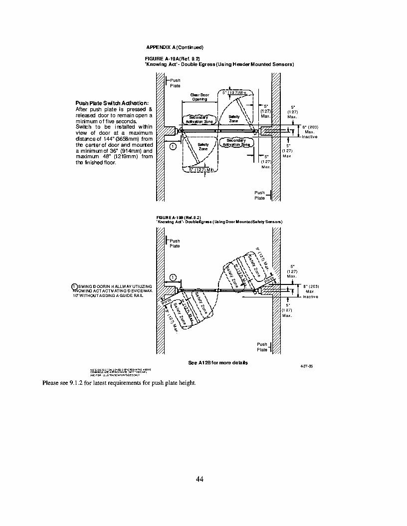
APPENDIX A(Continued)
FIGURE A-19A{Ref. 9.2)'Knowl1lJ Act'- Double Egress {Using Header Mounted Sensors)
Push Plate Switch Adivation:After push plate is pressed &releasoo door to remain open amirimum of five seconds.Switch to be installed withinview of door at a maximumdistalce of 144" (3658mm) fromthe cerner of door and mourteda minimum of 36" (914mm) andmaximum 48" (1219mm) fromthe finished floor.
fi)SWING 0 OCRIN HALLWAY UTIUZING):)<low ING ACT ACTIV ATING 0 EVICE MAX.10'WITHOUTADDING AGUIDE RAIL
I'"'C-t._--:::--,,\aesrDoor r 5" (127)M.jg,;._~
O~n~g ~~'~;>-l/' \!
I I \ I5eCord..,y--- I Safety \ \ J
AcIIvslloo 2bne Zooe \ \
FGURE A-191l (REI.9.2)'Knowing Act'· OoubleEgress (Using Door Mounled5afety Sensors)
NOTE:DETECOON ZONES 0 8"ICTEDI NTliE ABOVEORNNINGS "'FE APPROXIMATE (NOTTOSCIt.E}AN) FOR I LLUSTllATlONPUAPOseSONlY.
See A128 for more dela ils4-27-05
Please see 9.1.2 for latest requirements for push plate height.
44

Appendix A (Continued)
AGUREA·19C (Ref. 9.2)'Knowing Act'· Double Egress (Using Control Mats)
5" (127) Min.
Note: See 7.5lor t1Yesholdrequirements.
-~
Secondary LActivation Mal
~ 5"(127Max_
II
I
/
~~-
5"9r /\'r/ "(127) / ,\Max. r-------l / \ \
j safely,'Secondary " Mat ,\
ActlvaUonMat , ,
Push Plate Switch Activation:After push plate is pressed &released door to remain open aminimum of fiveseconds.Switch to be installed withinview of door at a maximumdistance of 144" (3658mm) fromthe center of door and mounteda minimum of36" (914mm) andmaximum 48" (1219mm) fromthe finished floor.
SEE DETAlLA7 FOR THRESHOLD DETAIL
45
APPENDIX B (NOT A PART OF ANSIIBHMA A156.10)
APPENDIX B
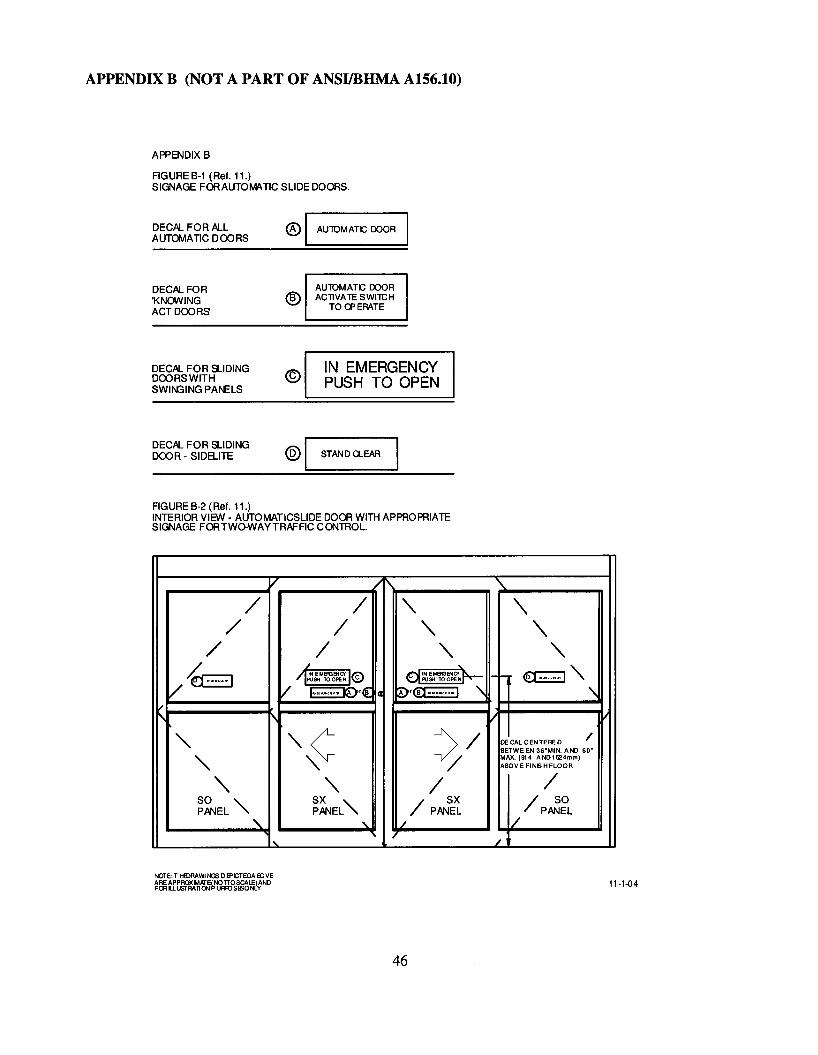
FIGURE B-1 (Ref. 11.)SIGNAGE FOR AUTOIvlATlC SLIDE DOORS.
DECAL FOR ALLAUTOIvIATIC DOORS
® I AUlOMATC DOOR I
DECAL FOR'KNOWINGACT DOORS
DECAL FOR SLIDINGDOORS WITHSWIr--GING PANELS
®
©
AUlOMATC DOORACllVA1E SWITCH
TOCPERATE
IN EMERGENCYPUSH TO OPEN
DECAL FOR SLIDINGDOOR - SIDELITE ® I STAND U-EAR
FIGURE B-2 (Ref. 11.)INTERIOR VIEW - AUTOMATICSLlDE DOOR WITH APPROPRIATESIGNAGE FORTWO-WAY TRAFFIC CO\lTROL.
V .1\
/ / " '\/ / " '\
/ / " "L ~
dINEMeGENCf~~"/I~~M~~~ I(§)
/~ .~
/ ~r{ ~r®.,..,".. 1 '\ '\vf\ 1'\ V ~
'" ,,~ )/ DECAL CENTERED /BETWEEN 36-MIN. AND 60·
'"MAX. (914 AND1524mm)
" / ABOVEFINISHFLOOR
'" " / /SO '" SX "
/ SX / SOPANEL PANEL PANEL 1/ PANEL
'" "- /
I ... /
46
11-1-04
APPENDIX 9
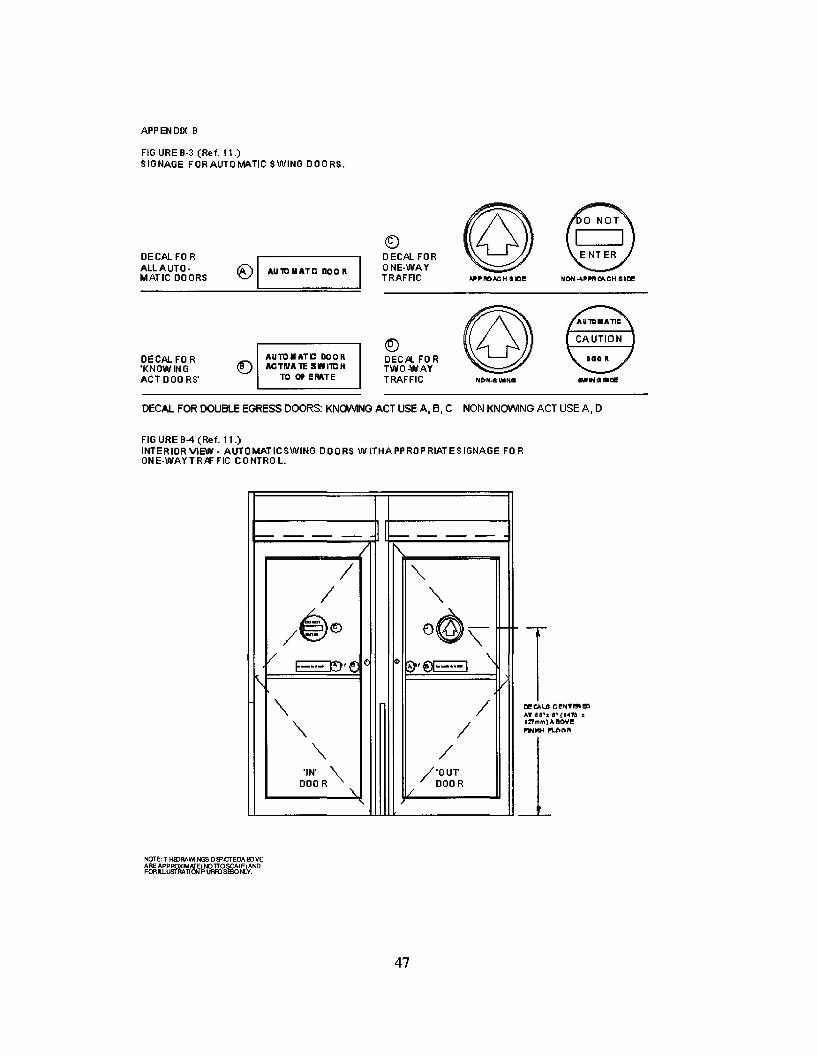
FIG URE 9-3 (Ref. 11.)SIGNAGE FORAUTOMATIC SWING DOORS.
DECAL FO RALLAUTOMATIC DOORS
DECAL FO R'KNOWINGACT 000 RS'
~ I AU1CIIATC DOOR I
AUTO II ATC DOO RACTntA 1C SllIIllC H
TO OP EMTE
®DECAL FORONE-WAYTRAFFIC
®DECA. FO RTWO-WAYTRAFFIC lIl\IfINlIiIlOl!
DECAL FOR DOUBLE EGRESS DOORS: KNQl.i\ANG ACT USE A,B, C NON KNOVVING ACT USE A, D
FIG URE 9-4 (Ref. 11.)INTERIOR VIEW - AUTOMATlCSWING DOORS W ITHAPPROPRIATESIGNAGE FO RON E-WAYTRAF FIC CONTRO L.
1
--- -- -- f--- -- -- --/ '\
/ '"/ '"/@~ 0@",/~,~c: ~ ~'€lI·_..-1 \
'\ i/
'" /
'" /
'" /'IN' '"
/'OUTDOOR "- / DOOR
47
TOI! e.>.L& e!N''''' I!IlAT l!l!I·t l!I·lloilWi :tl:nt"Il'I"l)" !lOY!~1oIH I'U>O~
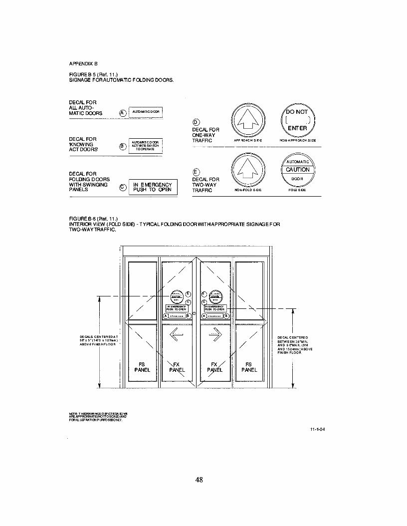
APPENDIX 8
FIGURE 8-5 (Ref. 11.)SIGNAGE FORAUTOMATIC FOLDING DOORS.
DECAL FOR
©All. AUTO- ([) I AuroM\~CDcm IMATICDOORS
C0DECAL FORONE-WAY
DECAL FOR TRAFFIC APPROACH BilE NON-APPROO!CH SIDE'KNOWING @)ACT DOORS
©DECAL FOR @)FOLIlNG DOORS DECAL FORWITH SWINGING 8 IN EMERGENCY TWO-WAYPANELS PUSH TO OPEN TRAFFIC NON.f'OLD SIDE FOLD SIDE
FIGURE 8-6 (Ref. 11.)INTERIOR VIEW (FOLD SIDE) - TYPICAL FOLDING DOORWITHAPPROPRIATE SIGNAGE FORTWO-WAYTRAFFIC.
DE CAL C EN TERE 0BETWE EN 36~tvUN.
AND 6 O"MAX. (914AN 0 1524mm )A BQVEFIN ISH FLOOR
J
/ '"/ '"r- -7 -~~ ()@'"mo. (C'J I(C") mO'
/ I~~M~~~ I I~N EMERiENCr'~PUSH TOOPEN
V A ........ B ®...m ...·I@ "-
r--
~ ~ENTEREDAT '" /3t127mm)
'" /ISHFLOOR
FS VX FX/ FSPANEL P~ ~EL PANEL
/
DECALS C58" tS" (147ABOVE FIN
NOTE:T HlDRAWINGS DEPICTEDA BJVEARE APPROXIMI<TE(NOTTOSCALE) ANDFOR ILLusrRA~ON P URfQSBSONLY.
11-1-04
48
APPENDIX C (NOT A PART OF ANSIIBHMA A156.10)
DEFINITIONS OF TERMS AS USED IN THE POWER OPERATED DOOR INDUSTRY.
Air Lock Air space between doors such as in a vestibule where only one door or set of doors can beopened at one time.
Approach Beam Photo-electric control beam used to activate an automatic door.
Automatic Entrance Package Complete entrance way containing door(s), frame, controls, andautomatic operator.
Bi-Parting Sliding Doors A pair of door leaves sliding away from each other to form a singlecommon door opening.
Bottom Arm (Hardware). The arm mechanism attached to the bottom rail of a door and connectingto the spindle of a floor closer, pivot or automatic door operator.
Break Out Opening The clear space in a doorway when a swinging or sliding door is operated in theemergency mode. This opening is not necessarily the same as the clear opening in the doorway whenthe door is operated in the normal mode.
Break Out Side The side of the opening to which the door swings when broken out.
Concealed Mounting Automatic door operators which are mounted above or below the door andpower the door through an inconspicuous pivot or arm.
Cover Plate In reference to door hardware, a finish plate used to cover the exposed face of a floorcloser not covered by the threshold; also a plate used to cover the exposed face of a closer or automaticdoor operator mounted in the head of the door frame.
Door Arm A device which is usually located in the top or bottom rail of a swinging automatic door.The function of this device is to provide suitable connection of the automatic door operator to the door. Itis concealed, semi-concealed or surface applied.
Door Light The glass area in a glazed door.
Door Size (Actual) For swinging or sliding doors, the actual width and height of the door leaf itself.
Flush Glazing A method of setting glass whereby glazing beads are recessed and flushed with the edgeof the frame.
Guard Bar. A protective bar applied to the lower portion of a door or sidelight to prevent collisionwith the glass.
Harness. A combination of wires and connectors providing connection of electrical controls tooperating equipment.
"In" Door. An automatic door installation designed for traffic into a building, space, etc.
In-Header Operator. A door operator completely contained in the door header requiring only electric,pneumatic or hydraulic power.
Left Hand Traffic. The traffic routing when the entrance door is placed to the left of adjacent exitdoors as viewed from the outside.
49
Lintel A horizontal structural member spanning an opening at its head to carry construction above theopening.
Masonry Opening. The wall opening into which the door is installed.
Meeting Stile The vertical edge of a door or window, in a pair, which is adjacent to the other door orwindow. A parallel meeting stile is one which has a beveled edge paralleling the edge of the door. Around meeting stile is one having a rounded edge.
Neolite Material is available from Biltrite Corp., P.O. Box 9045, Waltham, MA 02254.
Opening Cycle Movement of a swinging or sliding door from closed position to fully open. Forswinging doors, this is normally 90 degrees.
"Out" Door. An automatic door installation designed for traffic out of a building or space.
Photoelectric Control A device which employs the use of a visible or invisible light beam across orthrough an opening. When the beam is interrupted by a person or object, a signal is generated.
Power Closing. The closing of a door by energy supplied from hydraulics, pneumatics or electricity.
Power Open The opening of a door by energy supplied by other than manual means.
Power Unit A remote mechanical device used to convert energy (usually electrical) to pneumatic,hydraulic, or mechanical energy for transmission to the actuator.
Pressure Relief. A safety device to guard against excessive pressure buildup. Usually withreference to pneumatic or hydraulic systems.
Prismatic Prismatic doors are used to identify bi-parting sliding doors that meet at an inside angle ofless than 180 degrees.
Pull Cord Switch A switch located above the doorway having a cord with handle extending downto approximately 6 feet above the floor. When the cord is pulled, a switch is closed and a signalgenerated which can be used to activate an automatic door operator.
Recessed Frame (Setting Frame) A frame set into the floor during construction which secures matsinto a frame provide flush condition between floor and mat surface.
Recycle A mode of operation of an automatic door operator that occurs when the door is in the closingportion of its travel and is actuated causing the door to immediately reverse and go to the open position.
Right Hand Traffic The traffic routing when the entrance door is placed to the right of adjacent exitdoors as viewed from the outside.
Self-contained Operator An automatic operator in which the actuator and the power unit are made as asingle unit.
Sequential or Latching Operation Operation of push switch to actuate and push switch to de-actuate.
Setting Blocks Small pieces of neoprene, lead or other material which are placed under the lower edgeof a sheet of glass to support it within a frame.
Single Slide Automatic Door An automatic door which has one sliding leaf, either left hand or righthand.
Sliding Left Hand Automatic Door. Automatic sliding doors are said to be left hand when the door isviewed from the break out side of the opening and it travels to the left side of the viewer to open.
50

Sliding Right Hand Automatic Door. Automatic sliding doors are said to be right hand when the dooris viewed from the break out side of the opening and it travels to the right side of the viewer to open.
Spring Closing The closing of a door by energy supplied by springs.
Strike An opening or retaining device provided in a frame, threshold or in the edge of a stile of aninactive door to receive a lock or latch bolt. (Also referred to as a Keeper or Strike Plate).
Synchronized Operators Operators connected together either mechanically or electrically forsimultaneous operation. (Synonyms - coactive, simultaneous.)
Trim, Recessed Mat. Material installed around the perimeter of a control mat securing it recessed intothe floor.
Unknowing Act. Activating a door operator, such as pressing a switch, without specific knowledge ofhow it is done or what will happen.
Variable Time Delay A device which is adjusted to change the time a door remains open, after removalof the activation signal.
Visible Mounting Automatic door operators which are mounted above the door, protruding from thewall, and drive the door with a visible bracket and arm are said to be visibly mounted.
Definitions of other terms are found in the American National Standard for Nomenclature for Steel Doorsand Steel Door Frames, ANSI A250.7, and in the other ANSI/BHMA A156 Series of Standards.
51
APPENDIX D (NOT A PART OF ANSIIBHMA A156.10)
Dl. REFERENCE TO OTHER STANDARDS
D1.1 When power operated fire doors are used, they are subject to the requirements of the Standardfor Fire Doors and Windows ANSIINFPA 80.
D1.2 Glazing in doors are subject to criteria in the Standard, Performance Specifications andMethods of Test for Safety Glazing Material Used in Buildings, ANSI Z97.1 or CPSC requirements.
D1.3 Where required by the authority having jurisdiction, products meeting the requirements of thisStandard shall also comply with applicable local building code requirements.
APPENDIX E (NOT A PART OF ANSIIBHMA A156.10)
E-1 CONFORMANCE CRITERIA
Certification that products offered meet the requirements of this Standard and conform to individualmanufacturer's drawings, specifications, standards and quality assurance practices are available and insome circumstances are required. Buyer requirements determine the need for proof of conformancesuch as first article inspection, test laboratory reports, or listings. Specifiers requiring assertions ofconformance utilize statements of conformance by individual manufacturers, or test reports acceptableto the buyer.
E-2 PRESERVATION, PACKAGING AND PACKING
Unless other arrangements between buyer and seller are made, preservation, packaging andpacking shall be sufficient to protect containers and their contents under normal shipping and handlingconditions from the source of supply to the destination point.
E-3 MARKING
Unless other arrangements between buyer and seller are made, marking shall be in accordance with theindividual manufacturer's standard practice.
E-4 MAINTENANCE
Automatic pedestrian doors require periodic maintenance and inspection to ensure compliance withthis standard. It is strongly recommended that all automatic pedestrian doors be inspected at the time ofinstallation, and at a minimum annually thereafter, by an inspector certified by the AmericanAssociation of Automatic Door Manufacturers (AAADM). It is also recommended that the doors bemaintained on a regular basis by a qualified professional per the manufacturer's instructions. AAADMencourages compliance to current standards at the time of service.
E-5 RECOMMENDED PRACTICES AND OTHER INFORMATION
Sensors The intent of this standard is to provide reasonable safety to humans. To establish sensorcompliance, human characteristics are required. Humans have instincts to protect themselves thatcannot otherwise be duplicated.
Sensor mounting varies from one installation to another, and field tests should be conducted on eachinstallation. AAADM has established a sensor walk test as part of its training of inspectors forcertification to this standard. The method is to use humans to conduct the walk test.
It is recommended that the AAADM procedure be used to establish sensor compliance with thisstandard. If new methods are determined AAADM can adopt them at a shorter cycle than it would taketo establish procedures through this standard.
52
This revision of the standard allows for reducing the Activating Zone Length below the required 43"length due to physical restrictions or environmental conditions that make it impractical to comply withthe 43" approach.
The exception will allow more automatic doors to be installed that may not qualify without theexception and is needed to expand the use of automatic doors for accessibility.
Examples that make it impractical or ineffective to comply with the 43" minimum activating length aredoors that are installed in a storefront with a narrow sidewalk or the inside of a store with conditionsthat are tight and cross traffic not intending to use the door would cause high recycle resulting in loss ofheat, AC or uncomfortable temperature control to the building and its employees.
Shorter vestibule depth may be desirable to create an airlock but doors spaced as normallyrecommended is not available. The shorter activating zone length can be placed inside the vestibule tohelp create a better air lock
Under these conditions the standard allows activating length to be reduced to 30" minimum and a"Caution Automatic Door" sign is required to be applied to the operating door panel.
Also where conditions exist as described above, another option is to follow the Knowing ActActivation where the re-activating zone can be reduced to 24" but in this condition the door must firstbe activated by a Knowing Act Switch such as a common push switch which would than tum on theactivating sensor/mat and across door presence sensors. This method has application in hospitalinteriors at a cross isle or other locations or where card access is required for security control.
Knowing Act Activation The knowing act switch should:
• preferably be located within one to five feet from the door; but never more than twelve feet.
• remain accessible from the swing side when the door is opened.
• not be located in a position where the user would be in the path of the moving door.
• be mounted so the user is in full sight of the door when activating the switch.
• have a installation height of a minimum of 24 in. and a maximum of 48 in.
• Fixed non-contact switches should have a detection range no greater than 12 in. (305mm) toensure a knowing act is utilized to activate the door.
Consult A1l7.! and other applicable building codes for additional information regarding accessibilityrequirements for the door and area around the door.
53
Vestibule depth Vestibule depth should be a minimum of 10 feet between doors to keep sensors ormats from overlapping and to give some degree of air lock.
Double Egress Swing Doors Added to the Standard in the 2005 edition. Their primary use is inhallways of office or hospital buildings where an automated door is needed. They are similar toKnowing Act Doors except due to location, use and type of user, a separate section was added toaddress preferred practices.
Two-Way traffic Caution In general, it is not recommended to design traffic flow for two way trafficthrough an automatic swing door. The better choice is an IN-OUT swing door, automatic sliding door,or folding door. However, where it is necessary due to space constraints, or to preserve an entrance forhistorical reasons, the standard provides the best practice.
Custom Installations The following comments are provided for guidance recognizing there will becertain installations that will require deviation from the Standard requirements. It is important toobtain guidance and approval from qualified experts. Slower speeds and lower forces should beconsidered to compensate for other variances.
Examples include but are not limited to:
• Special security installations such as airport checkpoints or government buildings.
• Historical or other existing buildings.
• Heavy draft and stack pressures.
• Security grilles needed to protect the automatic entrance during the night. Placement of guide railsin the required position may interfere, necessitating setting the rail back an inch or so.
• Air locks in office buildings with high stack pressure needed next to a revolving door foraccessibility.
These should be countered by additional caution signage or sensors, restricting traffic, or reducing thedoor speed in both opening and closing. Activating zone, opening and closing force, speed, and safetyzone requirements should be considered.
Determination of sliding door closing speeds Typical 48 inch aluminum door panels with JA glassdo not exceed the 160 pound weight limit established in 10.1.1. Double glazed or stainless steel claddoors do exceed the limit, and the closing speed need to be adjusted. For example, a 200 pound doorwould be set to a closing speed of 1.25 seconds per foot maximum; a 250 pound door would be set to aclosing speed 1.5 seconds per foot maximum. See formula in 10.1.
54