berger automating with simatic s7-300 inside tia...
TRANSCRIPT

Berger Automating with SIMATIC S7-300 inside TIA Portal
Automating with SIMATIC S7-300 inside TIA PortalConfiguring Programming and Testing with STEP 7 Professional
by Hans Berger
2nd edition 2014
Publicis Publishing
The Deutsche Nationalbibliothek lists this publication in the Deutsche Nationalbibliografie detailed bibliographic data are available on the Internet at httpdnbd-nbde
The author translators and publisher have taken great care with all texts and illustrations in this book Nevertheless errors can never be completely avoided The author translators and publisher accept no liability for whatever legal reasons for any damage resulting from the use of the programming examples
wwwpublicis-booksde
Print ISBN 978-3-89578-443-9 ePDF ISBN 978-3-89578-924-3
2nd edition 2014
Editor Siemens Aktiengesellschaft Berlin and Munich Publisher Publicis Publishing Erlangencopy 2014 by Publicis Erlangen Zweigniederlassung der PWW GmbH
The publication and all parts thereof are protected by copyright Any use of it outside the strict provisions of the copyright law without the consent of the publisher is forbidden and will incur penalties This applies particularly to reproduction translation microfilming or other processing and to storage or processing in electronic systems It also applies to the use of individual figures and extracts from the text
Printed in Germany
Preface
5
Preface
The SIMATIC automation system unites all of the subsystems of an automationsolution under a uniform system architecture to form a homogenous whole fromthe field level right up to process control
The Totally Integrated Automation (TIA) concept permits uniform handling of all au-tomation components using a single system platform and tools with uniform oper-ator interfaces These requirements are fulfilled by the SIMATIC automation sys-tem which provides uniformity for configuration programming data manage-ment and communication
This book describes the hardware components of the SIMATIC S7-300 automationsystem with standard controllers and the features provided for designing a distrib-uted control concept with PROFIBUS and PROFINET To permit communication withother automation systems the controllers offer integrated bus interfaces for multi-point interface (MPI) PROFIBUS and Industrial Ethernet
The STEP 7 Professional engineering software inside TIA Portal makes it possible touse the complete functionality of the S7-300 controllers STEP 7 Professional is thecommon tool for hardware configuration generation of the user program and forprogram testing and diagnostics
STEP 7 Professional provides five programming languages for generation of the us-er program Ladder logic (LAD) with a graphic representation similar to a circuit di-agram function block diagram (FBD) with a graphic representation based on elec-tronic circuitry systems statement list (STL) with formulation of the control task asa list of commands at machine level a high-level Structured Control Language(SCL) similar to Pascal and finally GRAPH as a sequencer with sequential process-ing of the user program
STEP 7 Professional supports testing of the user program by means of watch tablesfor monitoring control and forcing of tag values by representation of the programwith the current tag values during ongoing operation and by offline simulation ofthe programmable controller
This book describes the configuration programming and testing of the S7-300 au-tomation system with the STEP 7 Professional engineering software Version 12 withService Pack 1 Update 2
Erlangen June 2014 Hans Berger
The contents of the book at a glance
6
The contents of the book at a glance
Start
Overview of the SIMATIC S7-300 automation system
Introduction to the SIMATIC STEP 7 Professional V12 engineering software
The basis of the automation solution Creating and editing a project
SIMATIC S7-300 automation system
Overview of the SIMATIC S7-300 modules Design of an automation system CPUs signal function and communication modules
Device configuration
Configuration of a station parameterization of modules and networking of stations
Tags addressing and data types
The properties of inputs outputs IO bit memories data and temporary local data as oper-and areas and how they are addressed absolute symbolic and indirect
Description of elementary and compound data types data types for block parameters point-ers and user data types
Program execution
How the CPU responds in the STARTUP RUN and STOP modes
How the user program is structured with blocks what the properties of these blocks are and how they are called
How the user program is executed startup characteristics main program interrupt process-ing troubleshooting and diagnostics
The program editor
Working with the PLC tag table creating and editing code and data blocks compiling blocks and evaluating program information
The ladder logic programming language LAD
The characteristics of LAD programming series and parallel connection of contacts the use of coils standard boxes Q boxes and ENENO boxes
The function block diagram programming language FBD
The characteristics of FBD programming boxes for binary logic operations the use of stan-dard boxes Q boxes and ENENO boxes
The statement list programming language STL
The characteristics of STL programming programming of binary logic operations applica-tion of digital functions and control of program execution
The contents of the book at a glance
7
The structured control language SCL
The characteristics of SCL programming operators and expressions working with binary and digital functions control of program execution using control statements
The S7-GRAPH sequential controller
What a sequential control is and what its elements are sequencers steps transitions and branches How a sequential control is configured using S7-GRAPH
Description of the control functions
Basic functions Functions for binary signals binary logic operations memory functions edge evaluations SIMATIC and IEC timer and counter functions
Digital functions Functions for digital tags transfer comparison arithmetic math conver-sion shift and logic functions
Program flow control Working with status bits programming jump functions calling and closing blocks using the master control relay
Online operation and program test
Connecting a programming device to the PLC station switching on online mode transfer-ring the project data and protecting the user program
Loading modifying deleting and comparing the user blocks
Working with the hardware diagnostics and testing the user program
Distributed IO
Overview The ET 200 distributed IO system
How a PROFINET IO system is configured and what properties it has
How a PROFIBUS DP master system is configured and what properties it has
How an actuatorsensor interface system is configured and what properties it has
Communication
The properties of S7 basic communication and of S7 communication and with what commu-nication functions they are programmed
The communication functions used to implement open user communication
Appendix
How external source files are created and imported for STL and SCL blocks
How a project created using STEP 7 V5x is migrated to the TIA Portal
How the user program is tested offline using the S7-PLCSIM simulation software
How the Web server is configured in the CPU and what features it offers
How block parameters and local tags are saved in the memory
Table of contents
8
Table of contents
1 Introduction 22
11 Overview of the S7-300 automation system 22111 SIMATIC S7-300 programmable controller 23112 Overview of STEP 7 Professional V12 24113 Five programming languages 26114 Execution of the user program 28115 Data management in the SIMATIC automation system 30
12 Introduction to STEP 7 Professional V12 31121 Installing STEP 7 31122 Automation License Manager 31123 Starting STEP 7 Professional 32124 Portal view 32125 The windows of the Project view 33126 Help information system 36127 Adapting the user interface 36
13 Editing a SIMATIC project 37131 Structured representation of project data 38132 Project data and editors for a PLC station 39133 Creating and editing a project 42134 Working with reference projects 44135 Creating and editing libraries 45
2 SIMATIC S7-300 automation system 46
21 S7-300 station components 4622 S7-300 CPUs 48
221 CPU versions 48222 Control and display elements 50223 SIMATIC Micro Memory Card 51224 Memory areas in an S7-300 station 51225 Bus interfaces 53
23 Signal modules 55231 Digital input modules 55232 Digital output modules 56233 Digital inputoutput modules 56234 Analog input modules 57235 Analog output modules 57236 Analog inputoutput modules 58
24 Function modules 59
25 Communication modules 60
Table of contents
9
26 Other modules 61261 Interface modules (IM) 61262 Power supply modules (PS) 62263 Simulator module 62264 Dummy module 62
27 SIPLUS S7-300 63
3 Device configuration 65
31 Introduction 65
32 Configuring a station 68321 Adding a PLC station 68322 Adding a module 68323 Adding an expansion rack 69
33 Parameterization of modules 70331 Parameterization of CPU properties 70332 Addressing modules 73333 Assigning parameters to signal modules 75
34 Configuring the network 76341 Introduction overview 76342 Networking stations 77343 Node addresses in a subnet 79344 Connections 80345 Configuring an MPI subnet 82346 Configuring a PROFIBUS subnet 83347 Configuring a PROFINET subnet 85348 Configuring an AS-i subnet 89
4 Tags addressing and data types 90
41 Operands and tags 90411 Introduction overview 90412 Operand areas inputs and outputs 91413 Operand area bit memory 93414 Operand area data 94415 Operand area temporary local data 95
42 Addressing of operands and tags 96421 Signal path 96422 Absolute addressing of tags 97423 Symbolic addressing of tags 101424 Addressing constants 102
43 Indirect addressing 103431 Memory-indirect addressing with STL 104432 Register-indirect addressing with STL 107433 Working with the address registers with STL 109434 Direct access to complex local tags with STL 116435 Indirect addressing with SCL 118
Table of contents
10
44 Elementary data types 120441 Introduction 120442 Bit-serial data types BOOL BYTE WORD and DWORD 123443 BCD numbers BCD16 and BCD32 123444 Fixed-point data types with sign INT and DINT 123445 Floating-point data type REAL 125446 Data type CHAR 126447 Data types for durations and points in time 127
45 Complex data types 128451 Data type DATE_AND_TIME 128452 Data type STRING 129453 Data type ARRAY 131454 Data type STRUCT 133
46 Parameter types and pointers 135461 Parameter types 135462 Pointer 136463 ldquoVariablerdquo ANY pointer with STL 139464 ldquoVariablerdquo ANY pointer with SCL 140
47 PLC data types 140
48 Start information 143
5 Program execution 145
51 Operating states of the CPU 145511 STOP operating state 146512 STARTUP operating state 147513 RUN operating state 149514 HOLD operating state 149515 Reset CPU memory 150516 Restoring the factory settings 150517 Retentive behavior of operands 150
52 Creating a user program 151521 Program draft 151522 Program execution 155523 Block types 156524 Editing block properties 158525 Block interface 161526 Example of use of block parameters 163
53 Calling blocks 165531 General information on calling of code blocks 165532 Calling functions (FC) 165533 Calling function blocks (FB) 167534 ldquoPassing onrdquo of block parameters 170
54 Startup program 171541 Organization block OB 100 171542 Determining a module address 171543 Parameterization of modules 173
Table of contents
11
55 Main program 176551 Organization block OB 1 176552 Process image updating 177553 Cycle time and response time 178554 Hold stop and protect program 181555 Time 182556 Read system time 184557 Runtime meter 184
56 Interrupt processing 186561 Introduction to interrupt processing 186562 Priority classes 187563 Time-of-day interrupt organization block OB 10 188564 Time-delay interrupts organization blocks OB 20 and OB 21 191565 Cyclic interrupts organization blocks OB 32 to OB 35 193566 Hardware interrupt organization block OB 40 195567 Interrupts for DPV1 organization blocks OB 55 to OB 57 196568 Isochronous mode interrupt organization block OB 61 197569 Reading additional interrupt information 199
57 Error handling 200571 Causes of errors and error responses 200572 Synchronous error 201573 Enabling and disabling synchronous error processing 202574 Enter substitute value 205575 Asynchronous errors 206576 Disable delay and enable interrupts and asynchronous errors 209
58 Diagnostics 211581 Diagnostic error interrupt organization block OB 82 211582 Read system state list 212583 Read start information 214584 Write user diagnostic event to the diagnostic buffer 215585 System diagnostics with Report System Errors 216
6 Program editor 218
61 Introduction 218
62 PLC tag table 218621 Working with PLC tag tables 219622 Defining and processing PLC tags 220623 Comparing PLC tags 221624 Exporting and importing a PLC tag table 222625 Constants tables 223
63 Programming a code block 223631 Creating a new code block 223632 Working area of the program editor for code blocks 224633 Specifying code block properties 226634 Programming a block interface 226635 Programming a control function 228
Table of contents
12
636 Editing tags 232637 Working with program comments 234
64 Programming a data block 236641 Creating a new data block 236642 Working area of program editor for data blocks 236643 Defining properties for data blocks 237644 Declaring data tags 238645 Entering data tags in global data blocks 239
65 Compiling blocks 239651 Starting the compilation 239652 Compiling SCL blocks 241653 Eliminating errors following compilation 241
66 Program information 242661 Cross-reference list 242662 Assignment list 244663 Call structure 245664 Dependency structure 246665 Consistency check 247666 Memory utilization of the CPU 248
7 Ladder logic LAD 249
71 Introduction 249711 Programming with LAD in general 249712 Program elements of ladder logic 251
72 Programming binary logic operations with LAD 252721 NO and NC contacts 252722 Series and parallel connection of contacts 253723 T branch open parallel branch 254724 Negating result of logic operation 255725 Edge evaluation of a binary tag 255726 Comparison contacts 256
73 Programming memory functions with LAD 257731 Simple coil assignment 257732 Set and reset coils 258733 Retentive response due to latching 259734 Coils with time response 260735 Coils with counter response 260
74 Programming Q boxes with LAD 261741 Memory boxes 261742 Edge evaluation of current flow 262743 SIMATIC timer functions 263744 SIMATIC counter functions 264745 IEC timer functions 265746 IEC counter functions 266
75 Programming ENENO boxes with LAD 267751 Transfer function MOVE 268
Table of contents
13
752 Arithmetic functions 269753 Math functions 269754 Conversion functions 270755 Shift functions 272756 Word logic operations 272
76 Controlling the program flow with LAD 274761 Working with status bits in the ladder logic 274762 ENENO mechanism with LAD 276763 Jump functions 277764 Block functions 278765 Master Control Relay (MCR) 280
8 Function block diagram FBD 282
81 Introduction 282811 Programming with FBD in general 282812 Program elements of the function block diagram 284
82 Programming binary logic operations with FBD 285821 Scanning for signal states ldquo1rdquo and ldquo0rdquo 285822 Programming a binary logic operation in the function block diagram 286823 AND function 287824 OR function 287825 Exclusive OR function 288826 Combined binary logic operations negating result of logic operation 288827 T branch 289828 Edge evaluation of binary tags 289829 Comparison functions 290
83 Programming standard boxes with FBD 291831 Assign box 291832 Set and reset boxes 292833 Standard boxes with time response 293834 Standard boxes with counter response 294
84 Programming Q boxes with FBD 294841 Memory boxes 295842 Edge evaluation of result of logic operation 296843 SIMATIC timer functions 297844 SIMATIC counter functions 297845 IEC timer functions 298846 IEC counter functions 299
85 Programming ENENO boxes with FBD 300851 Transfer function MOVE 301852 Arithmetic functions 302853 Math functions 303854 Conversion functions 303855 Shift functions 305856 Word logic operations 306
Table of contents
14
86 Controlling the program flow with FBD 307861 Working with status bits in the function block diagram 308862 ENENO mechanism with FBD 309863 Jump functions 310864 Block functions 312865 Master Control Relay (MCR) 313
9 Statement list STL 315
91 Introduction 315911 Programming with STL in general 315912 Structure of an STL statement 316
92 Programming binary logic operations with STL 317921 Processing of a binary logic operation operation step 317922 Scanning for signal states ldquo1rdquo and ldquo0rdquo 319923 Programming a binary logic operation in the statement list 320924 AND function 321925 OR function 321926 Exclusive OR function 321927 Combined binary logic operations 322928 Control of result of logic operation 324
93 Programming memory functions with STL 325931 Assignment 326932 Setting and resetting 326933 Edge evaluation 327
94 Programming timer and counter functions with STL 328941 SIMATIC timer functions 328942 SIMATIC counter functions 330943 IEC timer functions 331944 IEC counter functions 332
95 Programming digital functions with STL 333951 Transfer functions 333952 Comparison functions 333953 Arithmetic functions 337954 Math functions 340955 Conversion functions 341956 Shift functions 342957 Word logic operations 345
96 Controlling the program flow with STL 347961 Working with status bits in the statement list 347962 ENENO mechanism with STL 349963 Jump functions 351964 Jump list 352965 Loop jump 353966 Block functions 354967 Master Control Relay (MCR) 356
Table of contents
15
97 Further STL functions 358971 Accumulator functions 358972 Adding of constants to accumulator 1 360973 Decrementing incrementing 361974 Null instructions 361
10 Structured Control Language SCL 363
101 Introduction to programming with SCL 3631011 Programming with SCL in general 3631012 SCL statements and operators 365
102 Programming binary logic operations with SCL 3671021 Scanning for signal states ldquo1rdquo and ldquo0rdquo 3671022 AND function 3681023 OR function 3691024 Exclusive OR function 3691025 Combined binary logic operations 3691026 Negating result of logic operation 370
103 Programming memory functions with SCL 3701031 Value assignment of a binary tag 3711032 Setting and resetting 3711033 Edge evaluation 371
104 Programming timer and counter functions with SCL 3721041 SIMATIC timer functions 3721042 SIMATIC counter functions 3731043 IEC timer functions 3741044 IEC counter functions 375
105 Programming digital functions with SCL 3751051 Transfer function value assignment of a digital tag 3761052 Comparison functions 3761053 Arithmetic functions 3771054 Math functions 3781055 Conversion functions 3791056 Shift functions 3801057 Word logic operations logic expression 381
106 Controlling the program flow with SCL 3821061 Working with the ENO tag 3821062 ENENO mechanism with SCL 3831063 Control statements 3851064 Block functions 394
11 S7-GRAPH sequential control 397
111 Introduction 3971111 What is a sequential control 3971112 Properties of a sequential control 3981113 Program for a sequential control quantity framework 3991114 Operating modes 399
Table of contents
16
1115 Procedure for configuration 400
112 Elements of a sequential control 4001121 Steps and transitions 4001122 Jumps in a sequential control 4021123 Branching of a sequencer 4021124 GRAPH-specific tags 4031125 Permanent instructions 4041126 Step and transition functions 4051127 Processing of actions 408
113 Configuring a sequential control 4141131 Programming the GRAPH function block 4141132 Configuring the sequencer structure 4151133 Programming steps and transitions 4171134 Programming permanent instructions 4181135 Configuring block-independent alarms 4191136 Attributes of the GRAPH function block 4191137 Using the GRAPH function block 420
114 Testing the sequential control 4221141 Loading the GRAPH function block 4221142 Settings for program testing 4221143 Using operating modes 4231144 Synchronization of a sequencer 4241145 Testing with program status 425
12 Basic functions 427
121 Binary logic operations 4271211 Introduction 4271212 Working with binary signals 4281213 AND function series connection 4311214 OR function parallel connection 4321215 Exclusive OR function non-equivalence function 4321216 Negate result of logic operation NOT contact 433
122 Memory functions 4351221 Introduction 4351222 Standard coil assignment 4351223 Single setting and resetting 4361224 Dominant setting and resetting memory function 4371225 Edge evaluation 438
123 SIMATIC timer functions 4431231 Overview 4431232 Programming a timer function 4441233 Timer response as pulse 4491234 Timer response as extended pulse 4511235 Timer response as ON delay 4531236 Timer response as retentive ON delay 4551237 Timer response as OFF delay 457
Table of contents
17
124 IEC timer functions 4591241 Introduction 4591242 Pulse generation TP 4591243 ON delay TON 4601244 OFF delay TOF 461
125 SIMATIC counter functions 4621251 Overview 4621252 Programming a counter function 4631253 Principle of operation of a counter function 4671254 Enabling a counter function with STL 468
126 IEC counter functions 4701261 Introduction 4701262 Up counter CTU 4701263 Down counter CTD 4711264 Updown counter CTUD 472
13 Digital functions 475
131 General information 475
132 Transfer functions 4761321 General information on the ldquosimplerdquo transfer function 4761322 MOVE box with LAD and FBD 4761323 Loading and transferring with STL 4781324 Value assignments with SCL 4791325 Copying and filling a data area in the work memory 4811326 Transfer data area from and to load memory 4831327 Control memory area with MCR dependency 485
133 Comparison functions 4871331 Execution of ldquosimplerdquo comparison function 4881332 Comparison function T_COMP 4881333 Comparison function S_COMP 490
134 Arithmetic functions 4911341 General function description 4911342 Data types and status bits for an arithmetic function 4931343 Execution of the arithmetic function 4941344 Arithmetic functions for date and time 495
135 Math functions 4961351 General function description 4961352 General execution of a math function 4971353 Trigonometric functions SIN COS TAN 4981354 Arc functions ASIN ACOS ATAN 4991355 Additional math functions 499
136 Conversion functions 5001361 Implicit data type conversion 5011362 Data type conversion of fixed-point numbers 5011363 Data type conversion of floating-point numbers 5051364 Data type conversion for datetime with T_CONV 507
Table of contents
18
1365 Data type conversion for data type STRING with S_CONV 5091366 Data type conversion of hexadecimal numbers 5101367 Scaling and unscaling 5111368 Further conversion functions 513
137 Shift functions 5141371 General function description 5141372 General execution of a shift function 5141373 Shift to right 5161374 Shift to left 5171375 Rotate to right 5181376 Rotate to left 5181377 Rotating by the condition code bit CC1 (STL) 519
138 Logic functions 5191381 Word logic operations 5191382 Invert 5221383 Code bit and set bit number 5231384 Selection and limiting functions 524
139 Functions for strings 526
14 Program flow control 530
141 Status bits 5311411 Description of the status bits 5311412 Controlling the status bits 5331413 Setting and resetting the result of logic operation 5341414 Controlling the binary result 5351415 Evaluating the status bits 538
142 Jump functions 5391421 Introduction 5391422 Absolute jump 5391423 Conditional jump functions 5411424 Jump functions depending on status bits 542
143 Block end functions 5451431 Block end function RET (LAD and FBD) 5451432 Block end functions BEC BEU and BE (STL) 5461433 RETURN statement (SCL) 546
144 Calling of code blocks 5471441 General information on block calls 5471442 Calling a function (FC) 5471443 Calling a function block (FB) 5491444 Change to a block without block parameter 551
145 Data block functions 5531451 Open data block 5551452 Additional data block functions with STL 5551453 Creating deleting and testing data blocks 556
146 Master control relay 5601461 Introduction 560
Table of contents
19
1462 MCR dependency 5601463 MCR area and MCR zone 5601464 MCR area and MCR zone with a block change 5631465 Instructions for the master control relay 563
15 Online operation and program test 564
151 Connection of a programming device to the PLC station 5651511 Settings on the programming device 5651512 Connecting the programming device to the PLC station 5661513 Switching on online mode 566
152 Transferring project data 5681521 Loading project data for the first time 5681522 Reloading the project data 5701523 Protection of the user program 5711524 Editing of online project without offline project 5721525 Working with the Micro Memory Card 573
153 Working with blocks in online mode 5741531 Introduction 5741532 Editing the online version of a block 5751533 Downloading a block to the CPU 5751534 Packing the work memory 5771535 Uploading blocks from the CPU 5771536 Working with setpoints 5791537 Comparing blocks 581
154 Hardware diagnostics 5831541 Status displays on the modules 5831542 Diagnostic information 5841543 Diagnostic buffer 5851544 Diagnostic functions 5861545 Online tools 5861546 Further diagnostic information via the programming device 587
155 Testing the user program 5881551 Defining the call environment 5891552 Testing with program status 5891553 Testing in single step mode 5931554 Monitoring of PLC tags 5961555 Monitoring of data tags 5961556 Testing with watch tables 5971557 Monitoring and modifying in the STOP operating state 6021558 Testing with the force table 603
16 Distributed IO 607
161 Introduction overview 607
162 ET 200 distributed IO system 6081621 ET 200M 6081622 ET 200MP 609
Table of contents
20
1623 ET 200S 6091624 ET 200SP 6101625 ET 200iSP 6111626 ET 200pro 6111627 ET 200eco and ET 200eco PN 612
163 PROFINET IO 6131631 PROFINET IO components 6131632 Addresses with PROFINET IO 6151633 Special PROFINET configurations 6181634 Configuring PROFINET IO 6191635 Coupling modules for PROFINET IO 6231636 Real-time communication in PROFINET 624
164 PROFIBUS DP 6281641 PROFIBUS DP components 6281642 Addresses with PROFIBUS DP 6321643 Configuring PROFIBUS DP 6351644 Coupling modules for PROFIBUS DP 6381645 Special functions for PROFIBUS DP 640
165 Isochronous mode 6411651 Introduction 6411652 Isochronous mode with PROFINET IO 6411653 Isochronous mode with PROFIBUS 645
166 System blocks for distributed IO 6481661 System blocks for PROFIBUS DP 6481662 System blocks for PROFIBUS DP and PROFINET IO 6521663 System blocks for PROFINET IO 655
167 Actuatorsensor interface 6571671 Components of actuatorsensor interface 6571672 Addresses on the actuatorsensor interface 6601673 Configuring the actuatorsensor interface with CP 343-2P 6601674 System functions for AS-i 661
17 Communication 663
171 Overview 663
172 S7 basic communication 6641721 Basics of station-internal S7 basic communication 6641722 Configuring of station-internal S7 basic communication 6651723 System blocks for station-internal S7 basic communication 6651724 Basics of station-external S7 basic communication 6671725 Configuring of station-external S7 basic communication 6681726 System blocks for station-external S7 basic communication 668
173 S7 communication 6711731 Basics 6711732 Configuring S7 communication 6711733 One-way data exchange 674
Table of contents
21
1734 Two-way data exchange 6751735 Monitoring functions 678
174 Open user communication 6781741 Basics 6781742 Establishing and clearing connections 6801743 Data transfer with TCP native or ISO-on-TCP 6821744 Data transfer with UDP 685
18 Appendix 687
181 Working with source files 6871811 General procedure 6871812 Programming a code block in the source file 6881813 Programming a data block in the source file 6921814 Programming a PLC data type in the source file 695
182 Migrating projects 696183 Simulation with the TIA Portal 700
1831 Differences from a real CPU 7001832 Starting and saving the simulation 7011833 Using the simulation 7021834 Testing the program with the simulation 7051835 Additional functions of PLCSIM 707
184 Web server 7071841 Enable Web server 7071842 Reading out Web information 7081843 Standard Web pages 709
185 Storage of local tags 7121851 Storage in global data blocks 7121852 Storage in instance data blocks 7131853 Storage in the temporary local data 7131854 Data storage of the block parameters of a function (FC) 7151855 Data storage of the block parameters of a function block (FB) 7171856 Data storage of a local instance in a multi-instance 718
Index 721
1 Introduction
22
1 Introduction
11 Overview of the S7-300 automation system
SIMATIC S7-300 is the modular mini PLC system for the lower and medium perfor-mance ranges (Fig 11) Different versions of the controllers allow the performanceto be matched to the respective application Depending on the requirements theprogrammable controller can be expanded by inputoutput modules for digital andanalog signals in up to four racks with eight modules each
Further expansion with inputoutput modules is made possible by the distributedIO over PROFIBUS or PROFINET Special designs of these modules for increased me-chanical demands allow their installation directly on site on the machine or plantSTEP 7 is used to configure and program the SIMATIC S7-300 controllers Data ex-change between the controllers the distributed IO and the programming deviceis carried out over SIMATIC NET
Fig 11 Components of the SIMATIC S7-300 automation system
SIMATIC controllers controlthe machine or plant
The distributed IO expands theinterface to the machine or plant
SIMATIC NET
SIMATIC DP STEP 7Professional V12
SIMATIC S7-300
Networking allowsand central online access
data exchange
Several versions of the controllersexpand the range of use
STEP 7 is the engineering softwarefor configuring and programming
SIMATIC S7-300 automation system
11 Overview of the S7-300 automation system
23
111 SIMATIC S7-300 programmable controller
The most important components of an S7-300 programmable controller are shownin Fig 12
The CPU contains the operating system and the user program The user program issaved powerfail-proof on the Micro Memory Card (MMC) which is inserted in theCPU The user program is executed in the CPUs work memory The bus interfacespresent on the CPU establish the connection to other programmable controllers
Signal modules (SM) are responsible for the connection to the controlled plantThese input and output modules are available for digital and analog signals
The function modules (FM) are signal-preprocessing ldquointelligentrdquo IO moduleswhich prepare signals coming from the process independent of the CPU and eitherreturn them directly to the process or make them available at the CPUs internal in-terface Function modules are responsible for handling functions which the CPUcannot usually execute quickly enough such as counting pulses positioning orcontrolling drives
The CP modules allow data transfer in excess of the possibilities provided by thestandard interfaces with regard to protocols and communication functions
In the case of an expansion the interface modules (IM) connect the central rackto a maximum of three expansion racks
Finally a power supply module provides the voltage required by the programma-ble controller
Fig 12 Components of an S7-300 controller
Expansion rack
Central rack SM modules
FM modules
CP modules
IM module
IM moduleCPU module
PS module
Rack
Components of an S7-300 controller
1 Introduction
24
112 Overview of STEP 7 Professional V12
STEP 7 is the central automation tool for SIMATIC STEP 7 requires authorization(licensing) and is executed on the current Microsoft Windows operating systemsConfiguration of an S7-300 controller is carried out in two views the Portal viewand the Project view
The Portal view is task-oriented
In the Start portal you can open an existing project create a new project or migratea project A ldquoprojectrdquo is a data structure containing all the programs and data re-quired for your automation task The most important STEP 7 tools and functionscan be accessed from here via further portals (Fig 13)
b In the Devices amp networks portal you configure the programmable controllersie you position the modules in a rack and set their parameters
b In the PLC programming portal you create the user program in the form of indi-vidual sections referred to as ldquoblocksrdquo
b The Visualization portal provides the most important tools for configuration andsimulation of HMI systems using SIMATIC WinCC
b In the Motion amp Technology portal you insert a technology object for PID Controland edit it
Fig 13 Tools in the Start portal of STEP 7 Professional V12
11 Overview of the S7-300 automation system
25
b The Online amp Diagnostics portal allows you to connect the programming deviceonline to a CPU You can control the CPUs operating modes and transfer and testthe user program
The Project view is an object-oriented view with several windows whose contentschange depending on the current activity In the Device configuration the focalpoint is the working area with the device to be configured The Device view in-cludes the rack and the modules which have already been positioned (Fig 14) Afurther window ndash the inspector window ndash displays the properties of the selectedmodule and the task card provides support by means of the hardware catalog withthe available modules The Network view allows networking between PLC and HMIstations
When carrying out PLC programming you edit the selected block in the workingarea You are again shown the properties of the selected object in the inspector win-dow where you can adjust them In this case the task card contains the programelements catalog with the available program elements and instructions The sameapplies to the processing of PLC tags or to online program testing using watch ta-bles
Fig 14 Example of a Project view working area of the device configuration
1 Introduction
26
And you always have a view of the project tree This contains all objects of the STEP 7project You can therefore select an object at any time for example a program blockor watch table and edit this object using the corresponding editors which start au-tomatically when the object is opened
113 Five programming languages
You can select between five programming languages for the user program ladderlogic (LAD) function block diagram (FBD) statement list (STL) structured controllanguage (SCL) and sequential control (GRAPH)
Using the ladder logic you program the control task based on the circuit diagramOperations on binary signal states are represented by serial or parallel arrange-ment of contacts and coils (Fig 15) Complex functions such as arithmetic func-tions are represented by boxes which you arrange like contacts or coils in the ladderlogic
Using the function block diagram you program the control task based on electroniccircuitry systems Binary operations are implemented by linking AND and OR func-tions and are terminated by memory boxes (Fig 16) Complex boxes are used to han-dle the operations on digital tags for example with arithmetic functions
Fig 15 Example of representation in ladder logic
Fig 16 Example of representation in function block diagram
11 Overview of the S7-300 automation system
27
Using the statement list you program the control task using a sequence of state-ments Every STL statement contains the specification of what has to be done andpossibly an operand with which the operation is executed STL is equally suitable forbinary and digital operations and for programming complex open-loop control tasks(Fig 17)
Fig 17 Example of STL statements
Fig 18 Example of SCL statements
Fig 19 Example of a GRAPH sequencer and step configuration
1 Introduction
28
Structured control language is particularly suitable for programming complex al-gorithms or for tasks in the area of data management The program is made up of SCLstatements which for example can be value assignments comparisons or controlstatements (Fig 18)
Using GRAPH you program a control task as a sequential control in which a se-quence of actions prevails The individual steps and branches are enabled by step en-abling conditions which can be programmed using LAD or FBD (Fig 19)
114 Execution of the user program
After the power supply has been switched on the control processor checks the con-sistency of the hardware and parameterizes the modules A startup program is thenexecuted once if present The startup program belongs to the user program whichyou produce Modules can be initialized for example by the startup program
The user program is usually divided into individual sections called ldquoblocksrdquo Orga-nization blocks (OB) represent the interface between operating system and userprogram The operating system calls an organization block for specific events andthe user program is then processed in it (Fig 110)
Function blocks (FB) and functions (FC) are available for structuring the programFunction blocks have a memory in which local tags are saved permanently func-tions do not have this memory
Fig 110 Execution of the user program
Startupprogram
Alarm and errorprogram
Mainprogram
Execution of the user program
Switching on
Updating of inputsand outputs
Interruption(alarm or error)
Operating modeSTARTUP
Operating system User program
Operating modeRUN
OB
OB
FBFC
FBFC
FBFC
FBFC
FBFC
FBFC
OB
Interruption
11 Overview of the S7-300 automation system
29
Program instructions are available for calling function blocks and functions (startof execution) Each block call can be assigned inputs and outputs referred to asldquoblock parametersrdquo During calling tags can be transferred with which the pro-gram in the block is to work In this manner a block can be repeatedly called with acertain function (eg addition of three tags) but with different parameters sets(eg for different calculations) (Fig 111)
The data of the user program is saved in data blocks (DB) Instance data blocks havea fixed assignment to a call of a function block and are the tag memory of the func-tion block Global data blocks contain data which is not assigned to any block
Following a startup the control processor updates the input and output signals inthe process images and calls the organization block OB 1 The main program ispresent here Structuring is also possible (and recommended) in the main pro-gram Once the main program has been processed the control processor returns tothe operating system retains (for example) communication with the programmingdevice updates the input and output signals and then recommences with execu-tion of the main program
Cyclic program execution is a feature of programmable logic controllers The userprogram is even executed if no actions are requested ldquofrom outsiderdquo eg if the con-trolled machine is not running This provides advantages when programmingFor example you program the ladder logic as if you were drawing a circuit diagramor program the function block diagram as if you were connecting electronic compo-nents Roughly speaking a programmable controller has a characteristic like forexample a contactor or relay control the many programmed operations are effec-tive quasi simultaneously ldquoin parallelrdquo
In addition to the cyclically executed main program it is possible to carry out inter-rupt-controlled program execution You must enable the corresponding interrupt
Fig 111 Example of two block calls with different tags in each case
Preface
5
Preface
The SIMATIC automation system unites all of the subsystems of an automationsolution under a uniform system architecture to form a homogenous whole fromthe field level right up to process control
The Totally Integrated Automation (TIA) concept permits uniform handling of all au-tomation components using a single system platform and tools with uniform oper-ator interfaces These requirements are fulfilled by the SIMATIC automation sys-tem which provides uniformity for configuration programming data manage-ment and communication
This book describes the hardware components of the SIMATIC S7-300 automationsystem with standard controllers and the features provided for designing a distrib-uted control concept with PROFIBUS and PROFINET To permit communication withother automation systems the controllers offer integrated bus interfaces for multi-point interface (MPI) PROFIBUS and Industrial Ethernet
The STEP 7 Professional engineering software inside TIA Portal makes it possible touse the complete functionality of the S7-300 controllers STEP 7 Professional is thecommon tool for hardware configuration generation of the user program and forprogram testing and diagnostics
STEP 7 Professional provides five programming languages for generation of the us-er program Ladder logic (LAD) with a graphic representation similar to a circuit di-agram function block diagram (FBD) with a graphic representation based on elec-tronic circuitry systems statement list (STL) with formulation of the control task asa list of commands at machine level a high-level Structured Control Language(SCL) similar to Pascal and finally GRAPH as a sequencer with sequential process-ing of the user program
STEP 7 Professional supports testing of the user program by means of watch tablesfor monitoring control and forcing of tag values by representation of the programwith the current tag values during ongoing operation and by offline simulation ofthe programmable controller
This book describes the configuration programming and testing of the S7-300 au-tomation system with the STEP 7 Professional engineering software Version 12 withService Pack 1 Update 2
Erlangen June 2014 Hans Berger
The contents of the book at a glance
6
The contents of the book at a glance
Start
Overview of the SIMATIC S7-300 automation system
Introduction to the SIMATIC STEP 7 Professional V12 engineering software
The basis of the automation solution Creating and editing a project
SIMATIC S7-300 automation system
Overview of the SIMATIC S7-300 modules Design of an automation system CPUs signal function and communication modules
Device configuration
Configuration of a station parameterization of modules and networking of stations
Tags addressing and data types
The properties of inputs outputs IO bit memories data and temporary local data as oper-and areas and how they are addressed absolute symbolic and indirect
Description of elementary and compound data types data types for block parameters point-ers and user data types
Program execution
How the CPU responds in the STARTUP RUN and STOP modes
How the user program is structured with blocks what the properties of these blocks are and how they are called
How the user program is executed startup characteristics main program interrupt process-ing troubleshooting and diagnostics
The program editor
Working with the PLC tag table creating and editing code and data blocks compiling blocks and evaluating program information
The ladder logic programming language LAD
The characteristics of LAD programming series and parallel connection of contacts the use of coils standard boxes Q boxes and ENENO boxes
The function block diagram programming language FBD
The characteristics of FBD programming boxes for binary logic operations the use of stan-dard boxes Q boxes and ENENO boxes
The statement list programming language STL
The characteristics of STL programming programming of binary logic operations applica-tion of digital functions and control of program execution
The contents of the book at a glance
7
The structured control language SCL
The characteristics of SCL programming operators and expressions working with binary and digital functions control of program execution using control statements
The S7-GRAPH sequential controller
What a sequential control is and what its elements are sequencers steps transitions and branches How a sequential control is configured using S7-GRAPH
Description of the control functions
Basic functions Functions for binary signals binary logic operations memory functions edge evaluations SIMATIC and IEC timer and counter functions
Digital functions Functions for digital tags transfer comparison arithmetic math conver-sion shift and logic functions
Program flow control Working with status bits programming jump functions calling and closing blocks using the master control relay
Online operation and program test
Connecting a programming device to the PLC station switching on online mode transfer-ring the project data and protecting the user program
Loading modifying deleting and comparing the user blocks
Working with the hardware diagnostics and testing the user program
Distributed IO
Overview The ET 200 distributed IO system
How a PROFINET IO system is configured and what properties it has
How a PROFIBUS DP master system is configured and what properties it has
How an actuatorsensor interface system is configured and what properties it has
Communication
The properties of S7 basic communication and of S7 communication and with what commu-nication functions they are programmed
The communication functions used to implement open user communication
Appendix
How external source files are created and imported for STL and SCL blocks
How a project created using STEP 7 V5x is migrated to the TIA Portal
How the user program is tested offline using the S7-PLCSIM simulation software
How the Web server is configured in the CPU and what features it offers
How block parameters and local tags are saved in the memory
Table of contents
8
Table of contents
1 Introduction 22
11 Overview of the S7-300 automation system 22111 SIMATIC S7-300 programmable controller 23112 Overview of STEP 7 Professional V12 24113 Five programming languages 26114 Execution of the user program 28115 Data management in the SIMATIC automation system 30
12 Introduction to STEP 7 Professional V12 31121 Installing STEP 7 31122 Automation License Manager 31123 Starting STEP 7 Professional 32124 Portal view 32125 The windows of the Project view 33126 Help information system 36127 Adapting the user interface 36
13 Editing a SIMATIC project 37131 Structured representation of project data 38132 Project data and editors for a PLC station 39133 Creating and editing a project 42134 Working with reference projects 44135 Creating and editing libraries 45
2 SIMATIC S7-300 automation system 46
21 S7-300 station components 4622 S7-300 CPUs 48
221 CPU versions 48222 Control and display elements 50223 SIMATIC Micro Memory Card 51224 Memory areas in an S7-300 station 51225 Bus interfaces 53
23 Signal modules 55231 Digital input modules 55232 Digital output modules 56233 Digital inputoutput modules 56234 Analog input modules 57235 Analog output modules 57236 Analog inputoutput modules 58
24 Function modules 59
25 Communication modules 60
Table of contents
9
26 Other modules 61261 Interface modules (IM) 61262 Power supply modules (PS) 62263 Simulator module 62264 Dummy module 62
27 SIPLUS S7-300 63
3 Device configuration 65
31 Introduction 65
32 Configuring a station 68321 Adding a PLC station 68322 Adding a module 68323 Adding an expansion rack 69
33 Parameterization of modules 70331 Parameterization of CPU properties 70332 Addressing modules 73333 Assigning parameters to signal modules 75
34 Configuring the network 76341 Introduction overview 76342 Networking stations 77343 Node addresses in a subnet 79344 Connections 80345 Configuring an MPI subnet 82346 Configuring a PROFIBUS subnet 83347 Configuring a PROFINET subnet 85348 Configuring an AS-i subnet 89
4 Tags addressing and data types 90
41 Operands and tags 90411 Introduction overview 90412 Operand areas inputs and outputs 91413 Operand area bit memory 93414 Operand area data 94415 Operand area temporary local data 95
42 Addressing of operands and tags 96421 Signal path 96422 Absolute addressing of tags 97423 Symbolic addressing of tags 101424 Addressing constants 102
43 Indirect addressing 103431 Memory-indirect addressing with STL 104432 Register-indirect addressing with STL 107433 Working with the address registers with STL 109434 Direct access to complex local tags with STL 116435 Indirect addressing with SCL 118
Table of contents
10
44 Elementary data types 120441 Introduction 120442 Bit-serial data types BOOL BYTE WORD and DWORD 123443 BCD numbers BCD16 and BCD32 123444 Fixed-point data types with sign INT and DINT 123445 Floating-point data type REAL 125446 Data type CHAR 126447 Data types for durations and points in time 127
45 Complex data types 128451 Data type DATE_AND_TIME 128452 Data type STRING 129453 Data type ARRAY 131454 Data type STRUCT 133
46 Parameter types and pointers 135461 Parameter types 135462 Pointer 136463 ldquoVariablerdquo ANY pointer with STL 139464 ldquoVariablerdquo ANY pointer with SCL 140
47 PLC data types 140
48 Start information 143
5 Program execution 145
51 Operating states of the CPU 145511 STOP operating state 146512 STARTUP operating state 147513 RUN operating state 149514 HOLD operating state 149515 Reset CPU memory 150516 Restoring the factory settings 150517 Retentive behavior of operands 150
52 Creating a user program 151521 Program draft 151522 Program execution 155523 Block types 156524 Editing block properties 158525 Block interface 161526 Example of use of block parameters 163
53 Calling blocks 165531 General information on calling of code blocks 165532 Calling functions (FC) 165533 Calling function blocks (FB) 167534 ldquoPassing onrdquo of block parameters 170
54 Startup program 171541 Organization block OB 100 171542 Determining a module address 171543 Parameterization of modules 173
Table of contents
11
55 Main program 176551 Organization block OB 1 176552 Process image updating 177553 Cycle time and response time 178554 Hold stop and protect program 181555 Time 182556 Read system time 184557 Runtime meter 184
56 Interrupt processing 186561 Introduction to interrupt processing 186562 Priority classes 187563 Time-of-day interrupt organization block OB 10 188564 Time-delay interrupts organization blocks OB 20 and OB 21 191565 Cyclic interrupts organization blocks OB 32 to OB 35 193566 Hardware interrupt organization block OB 40 195567 Interrupts for DPV1 organization blocks OB 55 to OB 57 196568 Isochronous mode interrupt organization block OB 61 197569 Reading additional interrupt information 199
57 Error handling 200571 Causes of errors and error responses 200572 Synchronous error 201573 Enabling and disabling synchronous error processing 202574 Enter substitute value 205575 Asynchronous errors 206576 Disable delay and enable interrupts and asynchronous errors 209
58 Diagnostics 211581 Diagnostic error interrupt organization block OB 82 211582 Read system state list 212583 Read start information 214584 Write user diagnostic event to the diagnostic buffer 215585 System diagnostics with Report System Errors 216
6 Program editor 218
61 Introduction 218
62 PLC tag table 218621 Working with PLC tag tables 219622 Defining and processing PLC tags 220623 Comparing PLC tags 221624 Exporting and importing a PLC tag table 222625 Constants tables 223
63 Programming a code block 223631 Creating a new code block 223632 Working area of the program editor for code blocks 224633 Specifying code block properties 226634 Programming a block interface 226635 Programming a control function 228
Table of contents
12
636 Editing tags 232637 Working with program comments 234
64 Programming a data block 236641 Creating a new data block 236642 Working area of program editor for data blocks 236643 Defining properties for data blocks 237644 Declaring data tags 238645 Entering data tags in global data blocks 239
65 Compiling blocks 239651 Starting the compilation 239652 Compiling SCL blocks 241653 Eliminating errors following compilation 241
66 Program information 242661 Cross-reference list 242662 Assignment list 244663 Call structure 245664 Dependency structure 246665 Consistency check 247666 Memory utilization of the CPU 248
7 Ladder logic LAD 249
71 Introduction 249711 Programming with LAD in general 249712 Program elements of ladder logic 251
72 Programming binary logic operations with LAD 252721 NO and NC contacts 252722 Series and parallel connection of contacts 253723 T branch open parallel branch 254724 Negating result of logic operation 255725 Edge evaluation of a binary tag 255726 Comparison contacts 256
73 Programming memory functions with LAD 257731 Simple coil assignment 257732 Set and reset coils 258733 Retentive response due to latching 259734 Coils with time response 260735 Coils with counter response 260
74 Programming Q boxes with LAD 261741 Memory boxes 261742 Edge evaluation of current flow 262743 SIMATIC timer functions 263744 SIMATIC counter functions 264745 IEC timer functions 265746 IEC counter functions 266
75 Programming ENENO boxes with LAD 267751 Transfer function MOVE 268
Table of contents
13
752 Arithmetic functions 269753 Math functions 269754 Conversion functions 270755 Shift functions 272756 Word logic operations 272
76 Controlling the program flow with LAD 274761 Working with status bits in the ladder logic 274762 ENENO mechanism with LAD 276763 Jump functions 277764 Block functions 278765 Master Control Relay (MCR) 280
8 Function block diagram FBD 282
81 Introduction 282811 Programming with FBD in general 282812 Program elements of the function block diagram 284
82 Programming binary logic operations with FBD 285821 Scanning for signal states ldquo1rdquo and ldquo0rdquo 285822 Programming a binary logic operation in the function block diagram 286823 AND function 287824 OR function 287825 Exclusive OR function 288826 Combined binary logic operations negating result of logic operation 288827 T branch 289828 Edge evaluation of binary tags 289829 Comparison functions 290
83 Programming standard boxes with FBD 291831 Assign box 291832 Set and reset boxes 292833 Standard boxes with time response 293834 Standard boxes with counter response 294
84 Programming Q boxes with FBD 294841 Memory boxes 295842 Edge evaluation of result of logic operation 296843 SIMATIC timer functions 297844 SIMATIC counter functions 297845 IEC timer functions 298846 IEC counter functions 299
85 Programming ENENO boxes with FBD 300851 Transfer function MOVE 301852 Arithmetic functions 302853 Math functions 303854 Conversion functions 303855 Shift functions 305856 Word logic operations 306
Table of contents
14
86 Controlling the program flow with FBD 307861 Working with status bits in the function block diagram 308862 ENENO mechanism with FBD 309863 Jump functions 310864 Block functions 312865 Master Control Relay (MCR) 313
9 Statement list STL 315
91 Introduction 315911 Programming with STL in general 315912 Structure of an STL statement 316
92 Programming binary logic operations with STL 317921 Processing of a binary logic operation operation step 317922 Scanning for signal states ldquo1rdquo and ldquo0rdquo 319923 Programming a binary logic operation in the statement list 320924 AND function 321925 OR function 321926 Exclusive OR function 321927 Combined binary logic operations 322928 Control of result of logic operation 324
93 Programming memory functions with STL 325931 Assignment 326932 Setting and resetting 326933 Edge evaluation 327
94 Programming timer and counter functions with STL 328941 SIMATIC timer functions 328942 SIMATIC counter functions 330943 IEC timer functions 331944 IEC counter functions 332
95 Programming digital functions with STL 333951 Transfer functions 333952 Comparison functions 333953 Arithmetic functions 337954 Math functions 340955 Conversion functions 341956 Shift functions 342957 Word logic operations 345
96 Controlling the program flow with STL 347961 Working with status bits in the statement list 347962 ENENO mechanism with STL 349963 Jump functions 351964 Jump list 352965 Loop jump 353966 Block functions 354967 Master Control Relay (MCR) 356
Table of contents
15
97 Further STL functions 358971 Accumulator functions 358972 Adding of constants to accumulator 1 360973 Decrementing incrementing 361974 Null instructions 361
10 Structured Control Language SCL 363
101 Introduction to programming with SCL 3631011 Programming with SCL in general 3631012 SCL statements and operators 365
102 Programming binary logic operations with SCL 3671021 Scanning for signal states ldquo1rdquo and ldquo0rdquo 3671022 AND function 3681023 OR function 3691024 Exclusive OR function 3691025 Combined binary logic operations 3691026 Negating result of logic operation 370
103 Programming memory functions with SCL 3701031 Value assignment of a binary tag 3711032 Setting and resetting 3711033 Edge evaluation 371
104 Programming timer and counter functions with SCL 3721041 SIMATIC timer functions 3721042 SIMATIC counter functions 3731043 IEC timer functions 3741044 IEC counter functions 375
105 Programming digital functions with SCL 3751051 Transfer function value assignment of a digital tag 3761052 Comparison functions 3761053 Arithmetic functions 3771054 Math functions 3781055 Conversion functions 3791056 Shift functions 3801057 Word logic operations logic expression 381
106 Controlling the program flow with SCL 3821061 Working with the ENO tag 3821062 ENENO mechanism with SCL 3831063 Control statements 3851064 Block functions 394
11 S7-GRAPH sequential control 397
111 Introduction 3971111 What is a sequential control 3971112 Properties of a sequential control 3981113 Program for a sequential control quantity framework 3991114 Operating modes 399
Table of contents
16
1115 Procedure for configuration 400
112 Elements of a sequential control 4001121 Steps and transitions 4001122 Jumps in a sequential control 4021123 Branching of a sequencer 4021124 GRAPH-specific tags 4031125 Permanent instructions 4041126 Step and transition functions 4051127 Processing of actions 408
113 Configuring a sequential control 4141131 Programming the GRAPH function block 4141132 Configuring the sequencer structure 4151133 Programming steps and transitions 4171134 Programming permanent instructions 4181135 Configuring block-independent alarms 4191136 Attributes of the GRAPH function block 4191137 Using the GRAPH function block 420
114 Testing the sequential control 4221141 Loading the GRAPH function block 4221142 Settings for program testing 4221143 Using operating modes 4231144 Synchronization of a sequencer 4241145 Testing with program status 425
12 Basic functions 427
121 Binary logic operations 4271211 Introduction 4271212 Working with binary signals 4281213 AND function series connection 4311214 OR function parallel connection 4321215 Exclusive OR function non-equivalence function 4321216 Negate result of logic operation NOT contact 433
122 Memory functions 4351221 Introduction 4351222 Standard coil assignment 4351223 Single setting and resetting 4361224 Dominant setting and resetting memory function 4371225 Edge evaluation 438
123 SIMATIC timer functions 4431231 Overview 4431232 Programming a timer function 4441233 Timer response as pulse 4491234 Timer response as extended pulse 4511235 Timer response as ON delay 4531236 Timer response as retentive ON delay 4551237 Timer response as OFF delay 457
Table of contents
17
124 IEC timer functions 4591241 Introduction 4591242 Pulse generation TP 4591243 ON delay TON 4601244 OFF delay TOF 461
125 SIMATIC counter functions 4621251 Overview 4621252 Programming a counter function 4631253 Principle of operation of a counter function 4671254 Enabling a counter function with STL 468
126 IEC counter functions 4701261 Introduction 4701262 Up counter CTU 4701263 Down counter CTD 4711264 Updown counter CTUD 472
13 Digital functions 475
131 General information 475
132 Transfer functions 4761321 General information on the ldquosimplerdquo transfer function 4761322 MOVE box with LAD and FBD 4761323 Loading and transferring with STL 4781324 Value assignments with SCL 4791325 Copying and filling a data area in the work memory 4811326 Transfer data area from and to load memory 4831327 Control memory area with MCR dependency 485
133 Comparison functions 4871331 Execution of ldquosimplerdquo comparison function 4881332 Comparison function T_COMP 4881333 Comparison function S_COMP 490
134 Arithmetic functions 4911341 General function description 4911342 Data types and status bits for an arithmetic function 4931343 Execution of the arithmetic function 4941344 Arithmetic functions for date and time 495
135 Math functions 4961351 General function description 4961352 General execution of a math function 4971353 Trigonometric functions SIN COS TAN 4981354 Arc functions ASIN ACOS ATAN 4991355 Additional math functions 499
136 Conversion functions 5001361 Implicit data type conversion 5011362 Data type conversion of fixed-point numbers 5011363 Data type conversion of floating-point numbers 5051364 Data type conversion for datetime with T_CONV 507
Table of contents
18
1365 Data type conversion for data type STRING with S_CONV 5091366 Data type conversion of hexadecimal numbers 5101367 Scaling and unscaling 5111368 Further conversion functions 513
137 Shift functions 5141371 General function description 5141372 General execution of a shift function 5141373 Shift to right 5161374 Shift to left 5171375 Rotate to right 5181376 Rotate to left 5181377 Rotating by the condition code bit CC1 (STL) 519
138 Logic functions 5191381 Word logic operations 5191382 Invert 5221383 Code bit and set bit number 5231384 Selection and limiting functions 524
139 Functions for strings 526
14 Program flow control 530
141 Status bits 5311411 Description of the status bits 5311412 Controlling the status bits 5331413 Setting and resetting the result of logic operation 5341414 Controlling the binary result 5351415 Evaluating the status bits 538
142 Jump functions 5391421 Introduction 5391422 Absolute jump 5391423 Conditional jump functions 5411424 Jump functions depending on status bits 542
143 Block end functions 5451431 Block end function RET (LAD and FBD) 5451432 Block end functions BEC BEU and BE (STL) 5461433 RETURN statement (SCL) 546
144 Calling of code blocks 5471441 General information on block calls 5471442 Calling a function (FC) 5471443 Calling a function block (FB) 5491444 Change to a block without block parameter 551
145 Data block functions 5531451 Open data block 5551452 Additional data block functions with STL 5551453 Creating deleting and testing data blocks 556
146 Master control relay 5601461 Introduction 560
Table of contents
19
1462 MCR dependency 5601463 MCR area and MCR zone 5601464 MCR area and MCR zone with a block change 5631465 Instructions for the master control relay 563
15 Online operation and program test 564
151 Connection of a programming device to the PLC station 5651511 Settings on the programming device 5651512 Connecting the programming device to the PLC station 5661513 Switching on online mode 566
152 Transferring project data 5681521 Loading project data for the first time 5681522 Reloading the project data 5701523 Protection of the user program 5711524 Editing of online project without offline project 5721525 Working with the Micro Memory Card 573
153 Working with blocks in online mode 5741531 Introduction 5741532 Editing the online version of a block 5751533 Downloading a block to the CPU 5751534 Packing the work memory 5771535 Uploading blocks from the CPU 5771536 Working with setpoints 5791537 Comparing blocks 581
154 Hardware diagnostics 5831541 Status displays on the modules 5831542 Diagnostic information 5841543 Diagnostic buffer 5851544 Diagnostic functions 5861545 Online tools 5861546 Further diagnostic information via the programming device 587
155 Testing the user program 5881551 Defining the call environment 5891552 Testing with program status 5891553 Testing in single step mode 5931554 Monitoring of PLC tags 5961555 Monitoring of data tags 5961556 Testing with watch tables 5971557 Monitoring and modifying in the STOP operating state 6021558 Testing with the force table 603
16 Distributed IO 607
161 Introduction overview 607
162 ET 200 distributed IO system 6081621 ET 200M 6081622 ET 200MP 609
Table of contents
20
1623 ET 200S 6091624 ET 200SP 6101625 ET 200iSP 6111626 ET 200pro 6111627 ET 200eco and ET 200eco PN 612
163 PROFINET IO 6131631 PROFINET IO components 6131632 Addresses with PROFINET IO 6151633 Special PROFINET configurations 6181634 Configuring PROFINET IO 6191635 Coupling modules for PROFINET IO 6231636 Real-time communication in PROFINET 624
164 PROFIBUS DP 6281641 PROFIBUS DP components 6281642 Addresses with PROFIBUS DP 6321643 Configuring PROFIBUS DP 6351644 Coupling modules for PROFIBUS DP 6381645 Special functions for PROFIBUS DP 640
165 Isochronous mode 6411651 Introduction 6411652 Isochronous mode with PROFINET IO 6411653 Isochronous mode with PROFIBUS 645
166 System blocks for distributed IO 6481661 System blocks for PROFIBUS DP 6481662 System blocks for PROFIBUS DP and PROFINET IO 6521663 System blocks for PROFINET IO 655
167 Actuatorsensor interface 6571671 Components of actuatorsensor interface 6571672 Addresses on the actuatorsensor interface 6601673 Configuring the actuatorsensor interface with CP 343-2P 6601674 System functions for AS-i 661
17 Communication 663
171 Overview 663
172 S7 basic communication 6641721 Basics of station-internal S7 basic communication 6641722 Configuring of station-internal S7 basic communication 6651723 System blocks for station-internal S7 basic communication 6651724 Basics of station-external S7 basic communication 6671725 Configuring of station-external S7 basic communication 6681726 System blocks for station-external S7 basic communication 668
173 S7 communication 6711731 Basics 6711732 Configuring S7 communication 6711733 One-way data exchange 674
Table of contents
21
1734 Two-way data exchange 6751735 Monitoring functions 678
174 Open user communication 6781741 Basics 6781742 Establishing and clearing connections 6801743 Data transfer with TCP native or ISO-on-TCP 6821744 Data transfer with UDP 685
18 Appendix 687
181 Working with source files 6871811 General procedure 6871812 Programming a code block in the source file 6881813 Programming a data block in the source file 6921814 Programming a PLC data type in the source file 695
182 Migrating projects 696183 Simulation with the TIA Portal 700
1831 Differences from a real CPU 7001832 Starting and saving the simulation 7011833 Using the simulation 7021834 Testing the program with the simulation 7051835 Additional functions of PLCSIM 707
184 Web server 7071841 Enable Web server 7071842 Reading out Web information 7081843 Standard Web pages 709
185 Storage of local tags 7121851 Storage in global data blocks 7121852 Storage in instance data blocks 7131853 Storage in the temporary local data 7131854 Data storage of the block parameters of a function (FC) 7151855 Data storage of the block parameters of a function block (FB) 7171856 Data storage of a local instance in a multi-instance 718
Index 721
1 Introduction
22
1 Introduction
11 Overview of the S7-300 automation system
SIMATIC S7-300 is the modular mini PLC system for the lower and medium perfor-mance ranges (Fig 11) Different versions of the controllers allow the performanceto be matched to the respective application Depending on the requirements theprogrammable controller can be expanded by inputoutput modules for digital andanalog signals in up to four racks with eight modules each
Further expansion with inputoutput modules is made possible by the distributedIO over PROFIBUS or PROFINET Special designs of these modules for increased me-chanical demands allow their installation directly on site on the machine or plantSTEP 7 is used to configure and program the SIMATIC S7-300 controllers Data ex-change between the controllers the distributed IO and the programming deviceis carried out over SIMATIC NET
Fig 11 Components of the SIMATIC S7-300 automation system
SIMATIC controllers controlthe machine or plant
The distributed IO expands theinterface to the machine or plant
SIMATIC NET
SIMATIC DP STEP 7Professional V12
SIMATIC S7-300
Networking allowsand central online access
data exchange
Several versions of the controllersexpand the range of use
STEP 7 is the engineering softwarefor configuring and programming
SIMATIC S7-300 automation system
11 Overview of the S7-300 automation system
23
111 SIMATIC S7-300 programmable controller
The most important components of an S7-300 programmable controller are shownin Fig 12
The CPU contains the operating system and the user program The user program issaved powerfail-proof on the Micro Memory Card (MMC) which is inserted in theCPU The user program is executed in the CPUs work memory The bus interfacespresent on the CPU establish the connection to other programmable controllers
Signal modules (SM) are responsible for the connection to the controlled plantThese input and output modules are available for digital and analog signals
The function modules (FM) are signal-preprocessing ldquointelligentrdquo IO moduleswhich prepare signals coming from the process independent of the CPU and eitherreturn them directly to the process or make them available at the CPUs internal in-terface Function modules are responsible for handling functions which the CPUcannot usually execute quickly enough such as counting pulses positioning orcontrolling drives
The CP modules allow data transfer in excess of the possibilities provided by thestandard interfaces with regard to protocols and communication functions
In the case of an expansion the interface modules (IM) connect the central rackto a maximum of three expansion racks
Finally a power supply module provides the voltage required by the programma-ble controller
Fig 12 Components of an S7-300 controller
Expansion rack
Central rack SM modules
FM modules
CP modules
IM module
IM moduleCPU module
PS module
Rack
Components of an S7-300 controller
1 Introduction
24
112 Overview of STEP 7 Professional V12
STEP 7 is the central automation tool for SIMATIC STEP 7 requires authorization(licensing) and is executed on the current Microsoft Windows operating systemsConfiguration of an S7-300 controller is carried out in two views the Portal viewand the Project view
The Portal view is task-oriented
In the Start portal you can open an existing project create a new project or migratea project A ldquoprojectrdquo is a data structure containing all the programs and data re-quired for your automation task The most important STEP 7 tools and functionscan be accessed from here via further portals (Fig 13)
b In the Devices amp networks portal you configure the programmable controllersie you position the modules in a rack and set their parameters
b In the PLC programming portal you create the user program in the form of indi-vidual sections referred to as ldquoblocksrdquo
b The Visualization portal provides the most important tools for configuration andsimulation of HMI systems using SIMATIC WinCC
b In the Motion amp Technology portal you insert a technology object for PID Controland edit it
Fig 13 Tools in the Start portal of STEP 7 Professional V12
11 Overview of the S7-300 automation system
25
b The Online amp Diagnostics portal allows you to connect the programming deviceonline to a CPU You can control the CPUs operating modes and transfer and testthe user program
The Project view is an object-oriented view with several windows whose contentschange depending on the current activity In the Device configuration the focalpoint is the working area with the device to be configured The Device view in-cludes the rack and the modules which have already been positioned (Fig 14) Afurther window ndash the inspector window ndash displays the properties of the selectedmodule and the task card provides support by means of the hardware catalog withthe available modules The Network view allows networking between PLC and HMIstations
When carrying out PLC programming you edit the selected block in the workingarea You are again shown the properties of the selected object in the inspector win-dow where you can adjust them In this case the task card contains the programelements catalog with the available program elements and instructions The sameapplies to the processing of PLC tags or to online program testing using watch ta-bles
Fig 14 Example of a Project view working area of the device configuration
1 Introduction
26
And you always have a view of the project tree This contains all objects of the STEP 7project You can therefore select an object at any time for example a program blockor watch table and edit this object using the corresponding editors which start au-tomatically when the object is opened
113 Five programming languages
You can select between five programming languages for the user program ladderlogic (LAD) function block diagram (FBD) statement list (STL) structured controllanguage (SCL) and sequential control (GRAPH)
Using the ladder logic you program the control task based on the circuit diagramOperations on binary signal states are represented by serial or parallel arrange-ment of contacts and coils (Fig 15) Complex functions such as arithmetic func-tions are represented by boxes which you arrange like contacts or coils in the ladderlogic
Using the function block diagram you program the control task based on electroniccircuitry systems Binary operations are implemented by linking AND and OR func-tions and are terminated by memory boxes (Fig 16) Complex boxes are used to han-dle the operations on digital tags for example with arithmetic functions
Fig 15 Example of representation in ladder logic
Fig 16 Example of representation in function block diagram
11 Overview of the S7-300 automation system
27
Using the statement list you program the control task using a sequence of state-ments Every STL statement contains the specification of what has to be done andpossibly an operand with which the operation is executed STL is equally suitable forbinary and digital operations and for programming complex open-loop control tasks(Fig 17)
Fig 17 Example of STL statements
Fig 18 Example of SCL statements
Fig 19 Example of a GRAPH sequencer and step configuration
1 Introduction
28
Structured control language is particularly suitable for programming complex al-gorithms or for tasks in the area of data management The program is made up of SCLstatements which for example can be value assignments comparisons or controlstatements (Fig 18)
Using GRAPH you program a control task as a sequential control in which a se-quence of actions prevails The individual steps and branches are enabled by step en-abling conditions which can be programmed using LAD or FBD (Fig 19)
114 Execution of the user program
After the power supply has been switched on the control processor checks the con-sistency of the hardware and parameterizes the modules A startup program is thenexecuted once if present The startup program belongs to the user program whichyou produce Modules can be initialized for example by the startup program
The user program is usually divided into individual sections called ldquoblocksrdquo Orga-nization blocks (OB) represent the interface between operating system and userprogram The operating system calls an organization block for specific events andthe user program is then processed in it (Fig 110)
Function blocks (FB) and functions (FC) are available for structuring the programFunction blocks have a memory in which local tags are saved permanently func-tions do not have this memory
Fig 110 Execution of the user program
Startupprogram
Alarm and errorprogram
Mainprogram
Execution of the user program
Switching on
Updating of inputsand outputs
Interruption(alarm or error)
Operating modeSTARTUP
Operating system User program
Operating modeRUN
OB
OB
FBFC
FBFC
FBFC
FBFC
FBFC
FBFC
OB
Interruption
11 Overview of the S7-300 automation system
29
Program instructions are available for calling function blocks and functions (startof execution) Each block call can be assigned inputs and outputs referred to asldquoblock parametersrdquo During calling tags can be transferred with which the pro-gram in the block is to work In this manner a block can be repeatedly called with acertain function (eg addition of three tags) but with different parameters sets(eg for different calculations) (Fig 111)
The data of the user program is saved in data blocks (DB) Instance data blocks havea fixed assignment to a call of a function block and are the tag memory of the func-tion block Global data blocks contain data which is not assigned to any block
Following a startup the control processor updates the input and output signals inthe process images and calls the organization block OB 1 The main program ispresent here Structuring is also possible (and recommended) in the main pro-gram Once the main program has been processed the control processor returns tothe operating system retains (for example) communication with the programmingdevice updates the input and output signals and then recommences with execu-tion of the main program
Cyclic program execution is a feature of programmable logic controllers The userprogram is even executed if no actions are requested ldquofrom outsiderdquo eg if the con-trolled machine is not running This provides advantages when programmingFor example you program the ladder logic as if you were drawing a circuit diagramor program the function block diagram as if you were connecting electronic compo-nents Roughly speaking a programmable controller has a characteristic like forexample a contactor or relay control the many programmed operations are effec-tive quasi simultaneously ldquoin parallelrdquo
In addition to the cyclically executed main program it is possible to carry out inter-rupt-controlled program execution You must enable the corresponding interrupt
Fig 111 Example of two block calls with different tags in each case

The contents of the book at a glance
7
The structured control language SCL
The characteristics of SCL programming operators and expressions working with binary and digital functions control of program execution using control statements
The S7-GRAPH sequential controller
What a sequential control is and what its elements are sequencers steps transitions and branches How a sequential control is configured using S7-GRAPH
Description of the control functions
Basic functions Functions for binary signals binary logic operations memory functions edge evaluations SIMATIC and IEC timer and counter functions
Digital functions Functions for digital tags transfer comparison arithmetic math conver-sion shift and logic functions
Program flow control Working with status bits programming jump functions calling and closing blocks using the master control relay
Online operation and program test
Connecting a programming device to the PLC station switching on online mode transfer-ring the project data and protecting the user program
Loading modifying deleting and comparing the user blocks
Working with the hardware diagnostics and testing the user program
Distributed IO
Overview The ET 200 distributed IO system
How a PROFINET IO system is configured and what properties it has
How a PROFIBUS DP master system is configured and what properties it has
How an actuatorsensor interface system is configured and what properties it has
Communication
The properties of S7 basic communication and of S7 communication and with what commu-nication functions they are programmed
The communication functions used to implement open user communication
Appendix
How external source files are created and imported for STL and SCL blocks
How a project created using STEP 7 V5x is migrated to the TIA Portal
How the user program is tested offline using the S7-PLCSIM simulation software
How the Web server is configured in the CPU and what features it offers
How block parameters and local tags are saved in the memory
Table of contents
8
Table of contents
1 Introduction 22
11 Overview of the S7-300 automation system 22111 SIMATIC S7-300 programmable controller 23112 Overview of STEP 7 Professional V12 24113 Five programming languages 26114 Execution of the user program 28115 Data management in the SIMATIC automation system 30
12 Introduction to STEP 7 Professional V12 31121 Installing STEP 7 31122 Automation License Manager 31123 Starting STEP 7 Professional 32124 Portal view 32125 The windows of the Project view 33126 Help information system 36127 Adapting the user interface 36
13 Editing a SIMATIC project 37131 Structured representation of project data 38132 Project data and editors for a PLC station 39133 Creating and editing a project 42134 Working with reference projects 44135 Creating and editing libraries 45
2 SIMATIC S7-300 automation system 46
21 S7-300 station components 4622 S7-300 CPUs 48
221 CPU versions 48222 Control and display elements 50223 SIMATIC Micro Memory Card 51224 Memory areas in an S7-300 station 51225 Bus interfaces 53
23 Signal modules 55231 Digital input modules 55232 Digital output modules 56233 Digital inputoutput modules 56234 Analog input modules 57235 Analog output modules 57236 Analog inputoutput modules 58
24 Function modules 59
25 Communication modules 60
Table of contents
9
26 Other modules 61261 Interface modules (IM) 61262 Power supply modules (PS) 62263 Simulator module 62264 Dummy module 62
27 SIPLUS S7-300 63
3 Device configuration 65
31 Introduction 65
32 Configuring a station 68321 Adding a PLC station 68322 Adding a module 68323 Adding an expansion rack 69
33 Parameterization of modules 70331 Parameterization of CPU properties 70332 Addressing modules 73333 Assigning parameters to signal modules 75
34 Configuring the network 76341 Introduction overview 76342 Networking stations 77343 Node addresses in a subnet 79344 Connections 80345 Configuring an MPI subnet 82346 Configuring a PROFIBUS subnet 83347 Configuring a PROFINET subnet 85348 Configuring an AS-i subnet 89
4 Tags addressing and data types 90
41 Operands and tags 90411 Introduction overview 90412 Operand areas inputs and outputs 91413 Operand area bit memory 93414 Operand area data 94415 Operand area temporary local data 95
42 Addressing of operands and tags 96421 Signal path 96422 Absolute addressing of tags 97423 Symbolic addressing of tags 101424 Addressing constants 102
43 Indirect addressing 103431 Memory-indirect addressing with STL 104432 Register-indirect addressing with STL 107433 Working with the address registers with STL 109434 Direct access to complex local tags with STL 116435 Indirect addressing with SCL 118
Table of contents
10
44 Elementary data types 120441 Introduction 120442 Bit-serial data types BOOL BYTE WORD and DWORD 123443 BCD numbers BCD16 and BCD32 123444 Fixed-point data types with sign INT and DINT 123445 Floating-point data type REAL 125446 Data type CHAR 126447 Data types for durations and points in time 127
45 Complex data types 128451 Data type DATE_AND_TIME 128452 Data type STRING 129453 Data type ARRAY 131454 Data type STRUCT 133
46 Parameter types and pointers 135461 Parameter types 135462 Pointer 136463 ldquoVariablerdquo ANY pointer with STL 139464 ldquoVariablerdquo ANY pointer with SCL 140
47 PLC data types 140
48 Start information 143
5 Program execution 145
51 Operating states of the CPU 145511 STOP operating state 146512 STARTUP operating state 147513 RUN operating state 149514 HOLD operating state 149515 Reset CPU memory 150516 Restoring the factory settings 150517 Retentive behavior of operands 150
52 Creating a user program 151521 Program draft 151522 Program execution 155523 Block types 156524 Editing block properties 158525 Block interface 161526 Example of use of block parameters 163
53 Calling blocks 165531 General information on calling of code blocks 165532 Calling functions (FC) 165533 Calling function blocks (FB) 167534 ldquoPassing onrdquo of block parameters 170
54 Startup program 171541 Organization block OB 100 171542 Determining a module address 171543 Parameterization of modules 173
Table of contents
11
55 Main program 176551 Organization block OB 1 176552 Process image updating 177553 Cycle time and response time 178554 Hold stop and protect program 181555 Time 182556 Read system time 184557 Runtime meter 184
56 Interrupt processing 186561 Introduction to interrupt processing 186562 Priority classes 187563 Time-of-day interrupt organization block OB 10 188564 Time-delay interrupts organization blocks OB 20 and OB 21 191565 Cyclic interrupts organization blocks OB 32 to OB 35 193566 Hardware interrupt organization block OB 40 195567 Interrupts for DPV1 organization blocks OB 55 to OB 57 196568 Isochronous mode interrupt organization block OB 61 197569 Reading additional interrupt information 199
57 Error handling 200571 Causes of errors and error responses 200572 Synchronous error 201573 Enabling and disabling synchronous error processing 202574 Enter substitute value 205575 Asynchronous errors 206576 Disable delay and enable interrupts and asynchronous errors 209
58 Diagnostics 211581 Diagnostic error interrupt organization block OB 82 211582 Read system state list 212583 Read start information 214584 Write user diagnostic event to the diagnostic buffer 215585 System diagnostics with Report System Errors 216
6 Program editor 218
61 Introduction 218
62 PLC tag table 218621 Working with PLC tag tables 219622 Defining and processing PLC tags 220623 Comparing PLC tags 221624 Exporting and importing a PLC tag table 222625 Constants tables 223
63 Programming a code block 223631 Creating a new code block 223632 Working area of the program editor for code blocks 224633 Specifying code block properties 226634 Programming a block interface 226635 Programming a control function 228
Table of contents
12
636 Editing tags 232637 Working with program comments 234
64 Programming a data block 236641 Creating a new data block 236642 Working area of program editor for data blocks 236643 Defining properties for data blocks 237644 Declaring data tags 238645 Entering data tags in global data blocks 239
65 Compiling blocks 239651 Starting the compilation 239652 Compiling SCL blocks 241653 Eliminating errors following compilation 241
66 Program information 242661 Cross-reference list 242662 Assignment list 244663 Call structure 245664 Dependency structure 246665 Consistency check 247666 Memory utilization of the CPU 248
7 Ladder logic LAD 249
71 Introduction 249711 Programming with LAD in general 249712 Program elements of ladder logic 251
72 Programming binary logic operations with LAD 252721 NO and NC contacts 252722 Series and parallel connection of contacts 253723 T branch open parallel branch 254724 Negating result of logic operation 255725 Edge evaluation of a binary tag 255726 Comparison contacts 256
73 Programming memory functions with LAD 257731 Simple coil assignment 257732 Set and reset coils 258733 Retentive response due to latching 259734 Coils with time response 260735 Coils with counter response 260
74 Programming Q boxes with LAD 261741 Memory boxes 261742 Edge evaluation of current flow 262743 SIMATIC timer functions 263744 SIMATIC counter functions 264745 IEC timer functions 265746 IEC counter functions 266
75 Programming ENENO boxes with LAD 267751 Transfer function MOVE 268
Table of contents
13
752 Arithmetic functions 269753 Math functions 269754 Conversion functions 270755 Shift functions 272756 Word logic operations 272
76 Controlling the program flow with LAD 274761 Working with status bits in the ladder logic 274762 ENENO mechanism with LAD 276763 Jump functions 277764 Block functions 278765 Master Control Relay (MCR) 280
8 Function block diagram FBD 282
81 Introduction 282811 Programming with FBD in general 282812 Program elements of the function block diagram 284
82 Programming binary logic operations with FBD 285821 Scanning for signal states ldquo1rdquo and ldquo0rdquo 285822 Programming a binary logic operation in the function block diagram 286823 AND function 287824 OR function 287825 Exclusive OR function 288826 Combined binary logic operations negating result of logic operation 288827 T branch 289828 Edge evaluation of binary tags 289829 Comparison functions 290
83 Programming standard boxes with FBD 291831 Assign box 291832 Set and reset boxes 292833 Standard boxes with time response 293834 Standard boxes with counter response 294
84 Programming Q boxes with FBD 294841 Memory boxes 295842 Edge evaluation of result of logic operation 296843 SIMATIC timer functions 297844 SIMATIC counter functions 297845 IEC timer functions 298846 IEC counter functions 299
85 Programming ENENO boxes with FBD 300851 Transfer function MOVE 301852 Arithmetic functions 302853 Math functions 303854 Conversion functions 303855 Shift functions 305856 Word logic operations 306
Table of contents
14
86 Controlling the program flow with FBD 307861 Working with status bits in the function block diagram 308862 ENENO mechanism with FBD 309863 Jump functions 310864 Block functions 312865 Master Control Relay (MCR) 313
9 Statement list STL 315
91 Introduction 315911 Programming with STL in general 315912 Structure of an STL statement 316
92 Programming binary logic operations with STL 317921 Processing of a binary logic operation operation step 317922 Scanning for signal states ldquo1rdquo and ldquo0rdquo 319923 Programming a binary logic operation in the statement list 320924 AND function 321925 OR function 321926 Exclusive OR function 321927 Combined binary logic operations 322928 Control of result of logic operation 324
93 Programming memory functions with STL 325931 Assignment 326932 Setting and resetting 326933 Edge evaluation 327
94 Programming timer and counter functions with STL 328941 SIMATIC timer functions 328942 SIMATIC counter functions 330943 IEC timer functions 331944 IEC counter functions 332
95 Programming digital functions with STL 333951 Transfer functions 333952 Comparison functions 333953 Arithmetic functions 337954 Math functions 340955 Conversion functions 341956 Shift functions 342957 Word logic operations 345
96 Controlling the program flow with STL 347961 Working with status bits in the statement list 347962 ENENO mechanism with STL 349963 Jump functions 351964 Jump list 352965 Loop jump 353966 Block functions 354967 Master Control Relay (MCR) 356
Table of contents
15
97 Further STL functions 358971 Accumulator functions 358972 Adding of constants to accumulator 1 360973 Decrementing incrementing 361974 Null instructions 361
10 Structured Control Language SCL 363
101 Introduction to programming with SCL 3631011 Programming with SCL in general 3631012 SCL statements and operators 365
102 Programming binary logic operations with SCL 3671021 Scanning for signal states ldquo1rdquo and ldquo0rdquo 3671022 AND function 3681023 OR function 3691024 Exclusive OR function 3691025 Combined binary logic operations 3691026 Negating result of logic operation 370
103 Programming memory functions with SCL 3701031 Value assignment of a binary tag 3711032 Setting and resetting 3711033 Edge evaluation 371
104 Programming timer and counter functions with SCL 3721041 SIMATIC timer functions 3721042 SIMATIC counter functions 3731043 IEC timer functions 3741044 IEC counter functions 375
105 Programming digital functions with SCL 3751051 Transfer function value assignment of a digital tag 3761052 Comparison functions 3761053 Arithmetic functions 3771054 Math functions 3781055 Conversion functions 3791056 Shift functions 3801057 Word logic operations logic expression 381
106 Controlling the program flow with SCL 3821061 Working with the ENO tag 3821062 ENENO mechanism with SCL 3831063 Control statements 3851064 Block functions 394
11 S7-GRAPH sequential control 397
111 Introduction 3971111 What is a sequential control 3971112 Properties of a sequential control 3981113 Program for a sequential control quantity framework 3991114 Operating modes 399
Table of contents
16
1115 Procedure for configuration 400
112 Elements of a sequential control 4001121 Steps and transitions 4001122 Jumps in a sequential control 4021123 Branching of a sequencer 4021124 GRAPH-specific tags 4031125 Permanent instructions 4041126 Step and transition functions 4051127 Processing of actions 408
113 Configuring a sequential control 4141131 Programming the GRAPH function block 4141132 Configuring the sequencer structure 4151133 Programming steps and transitions 4171134 Programming permanent instructions 4181135 Configuring block-independent alarms 4191136 Attributes of the GRAPH function block 4191137 Using the GRAPH function block 420
114 Testing the sequential control 4221141 Loading the GRAPH function block 4221142 Settings for program testing 4221143 Using operating modes 4231144 Synchronization of a sequencer 4241145 Testing with program status 425
12 Basic functions 427
121 Binary logic operations 4271211 Introduction 4271212 Working with binary signals 4281213 AND function series connection 4311214 OR function parallel connection 4321215 Exclusive OR function non-equivalence function 4321216 Negate result of logic operation NOT contact 433
122 Memory functions 4351221 Introduction 4351222 Standard coil assignment 4351223 Single setting and resetting 4361224 Dominant setting and resetting memory function 4371225 Edge evaluation 438
123 SIMATIC timer functions 4431231 Overview 4431232 Programming a timer function 4441233 Timer response as pulse 4491234 Timer response as extended pulse 4511235 Timer response as ON delay 4531236 Timer response as retentive ON delay 4551237 Timer response as OFF delay 457
Table of contents
17
124 IEC timer functions 4591241 Introduction 4591242 Pulse generation TP 4591243 ON delay TON 4601244 OFF delay TOF 461
125 SIMATIC counter functions 4621251 Overview 4621252 Programming a counter function 4631253 Principle of operation of a counter function 4671254 Enabling a counter function with STL 468
126 IEC counter functions 4701261 Introduction 4701262 Up counter CTU 4701263 Down counter CTD 4711264 Updown counter CTUD 472
13 Digital functions 475
131 General information 475
132 Transfer functions 4761321 General information on the ldquosimplerdquo transfer function 4761322 MOVE box with LAD and FBD 4761323 Loading and transferring with STL 4781324 Value assignments with SCL 4791325 Copying and filling a data area in the work memory 4811326 Transfer data area from and to load memory 4831327 Control memory area with MCR dependency 485
133 Comparison functions 4871331 Execution of ldquosimplerdquo comparison function 4881332 Comparison function T_COMP 4881333 Comparison function S_COMP 490
134 Arithmetic functions 4911341 General function description 4911342 Data types and status bits for an arithmetic function 4931343 Execution of the arithmetic function 4941344 Arithmetic functions for date and time 495
135 Math functions 4961351 General function description 4961352 General execution of a math function 4971353 Trigonometric functions SIN COS TAN 4981354 Arc functions ASIN ACOS ATAN 4991355 Additional math functions 499
136 Conversion functions 5001361 Implicit data type conversion 5011362 Data type conversion of fixed-point numbers 5011363 Data type conversion of floating-point numbers 5051364 Data type conversion for datetime with T_CONV 507
Table of contents
18
1365 Data type conversion for data type STRING with S_CONV 5091366 Data type conversion of hexadecimal numbers 5101367 Scaling and unscaling 5111368 Further conversion functions 513
137 Shift functions 5141371 General function description 5141372 General execution of a shift function 5141373 Shift to right 5161374 Shift to left 5171375 Rotate to right 5181376 Rotate to left 5181377 Rotating by the condition code bit CC1 (STL) 519
138 Logic functions 5191381 Word logic operations 5191382 Invert 5221383 Code bit and set bit number 5231384 Selection and limiting functions 524
139 Functions for strings 526
14 Program flow control 530
141 Status bits 5311411 Description of the status bits 5311412 Controlling the status bits 5331413 Setting and resetting the result of logic operation 5341414 Controlling the binary result 5351415 Evaluating the status bits 538
142 Jump functions 5391421 Introduction 5391422 Absolute jump 5391423 Conditional jump functions 5411424 Jump functions depending on status bits 542
143 Block end functions 5451431 Block end function RET (LAD and FBD) 5451432 Block end functions BEC BEU and BE (STL) 5461433 RETURN statement (SCL) 546
144 Calling of code blocks 5471441 General information on block calls 5471442 Calling a function (FC) 5471443 Calling a function block (FB) 5491444 Change to a block without block parameter 551
145 Data block functions 5531451 Open data block 5551452 Additional data block functions with STL 5551453 Creating deleting and testing data blocks 556
146 Master control relay 5601461 Introduction 560
Table of contents
19
1462 MCR dependency 5601463 MCR area and MCR zone 5601464 MCR area and MCR zone with a block change 5631465 Instructions for the master control relay 563
15 Online operation and program test 564
151 Connection of a programming device to the PLC station 5651511 Settings on the programming device 5651512 Connecting the programming device to the PLC station 5661513 Switching on online mode 566
152 Transferring project data 5681521 Loading project data for the first time 5681522 Reloading the project data 5701523 Protection of the user program 5711524 Editing of online project without offline project 5721525 Working with the Micro Memory Card 573
153 Working with blocks in online mode 5741531 Introduction 5741532 Editing the online version of a block 5751533 Downloading a block to the CPU 5751534 Packing the work memory 5771535 Uploading blocks from the CPU 5771536 Working with setpoints 5791537 Comparing blocks 581
154 Hardware diagnostics 5831541 Status displays on the modules 5831542 Diagnostic information 5841543 Diagnostic buffer 5851544 Diagnostic functions 5861545 Online tools 5861546 Further diagnostic information via the programming device 587
155 Testing the user program 5881551 Defining the call environment 5891552 Testing with program status 5891553 Testing in single step mode 5931554 Monitoring of PLC tags 5961555 Monitoring of data tags 5961556 Testing with watch tables 5971557 Monitoring and modifying in the STOP operating state 6021558 Testing with the force table 603
16 Distributed IO 607
161 Introduction overview 607
162 ET 200 distributed IO system 6081621 ET 200M 6081622 ET 200MP 609
Table of contents
20
1623 ET 200S 6091624 ET 200SP 6101625 ET 200iSP 6111626 ET 200pro 6111627 ET 200eco and ET 200eco PN 612
163 PROFINET IO 6131631 PROFINET IO components 6131632 Addresses with PROFINET IO 6151633 Special PROFINET configurations 6181634 Configuring PROFINET IO 6191635 Coupling modules for PROFINET IO 6231636 Real-time communication in PROFINET 624
164 PROFIBUS DP 6281641 PROFIBUS DP components 6281642 Addresses with PROFIBUS DP 6321643 Configuring PROFIBUS DP 6351644 Coupling modules for PROFIBUS DP 6381645 Special functions for PROFIBUS DP 640
165 Isochronous mode 6411651 Introduction 6411652 Isochronous mode with PROFINET IO 6411653 Isochronous mode with PROFIBUS 645
166 System blocks for distributed IO 6481661 System blocks for PROFIBUS DP 6481662 System blocks for PROFIBUS DP and PROFINET IO 6521663 System blocks for PROFINET IO 655
167 Actuatorsensor interface 6571671 Components of actuatorsensor interface 6571672 Addresses on the actuatorsensor interface 6601673 Configuring the actuatorsensor interface with CP 343-2P 6601674 System functions for AS-i 661
17 Communication 663
171 Overview 663
172 S7 basic communication 6641721 Basics of station-internal S7 basic communication 6641722 Configuring of station-internal S7 basic communication 6651723 System blocks for station-internal S7 basic communication 6651724 Basics of station-external S7 basic communication 6671725 Configuring of station-external S7 basic communication 6681726 System blocks for station-external S7 basic communication 668
173 S7 communication 6711731 Basics 6711732 Configuring S7 communication 6711733 One-way data exchange 674
Table of contents
21
1734 Two-way data exchange 6751735 Monitoring functions 678
174 Open user communication 6781741 Basics 6781742 Establishing and clearing connections 6801743 Data transfer with TCP native or ISO-on-TCP 6821744 Data transfer with UDP 685
18 Appendix 687
181 Working with source files 6871811 General procedure 6871812 Programming a code block in the source file 6881813 Programming a data block in the source file 6921814 Programming a PLC data type in the source file 695
182 Migrating projects 696183 Simulation with the TIA Portal 700
1831 Differences from a real CPU 7001832 Starting and saving the simulation 7011833 Using the simulation 7021834 Testing the program with the simulation 7051835 Additional functions of PLCSIM 707
184 Web server 7071841 Enable Web server 7071842 Reading out Web information 7081843 Standard Web pages 709
185 Storage of local tags 7121851 Storage in global data blocks 7121852 Storage in instance data blocks 7131853 Storage in the temporary local data 7131854 Data storage of the block parameters of a function (FC) 7151855 Data storage of the block parameters of a function block (FB) 7171856 Data storage of a local instance in a multi-instance 718
Index 721
1 Introduction
22
1 Introduction
11 Overview of the S7-300 automation system
SIMATIC S7-300 is the modular mini PLC system for the lower and medium perfor-mance ranges (Fig 11) Different versions of the controllers allow the performanceto be matched to the respective application Depending on the requirements theprogrammable controller can be expanded by inputoutput modules for digital andanalog signals in up to four racks with eight modules each
Further expansion with inputoutput modules is made possible by the distributedIO over PROFIBUS or PROFINET Special designs of these modules for increased me-chanical demands allow their installation directly on site on the machine or plantSTEP 7 is used to configure and program the SIMATIC S7-300 controllers Data ex-change between the controllers the distributed IO and the programming deviceis carried out over SIMATIC NET
Fig 11 Components of the SIMATIC S7-300 automation system
SIMATIC controllers controlthe machine or plant
The distributed IO expands theinterface to the machine or plant
SIMATIC NET
SIMATIC DP STEP 7Professional V12
SIMATIC S7-300
Networking allowsand central online access
data exchange
Several versions of the controllersexpand the range of use
STEP 7 is the engineering softwarefor configuring and programming
SIMATIC S7-300 automation system
11 Overview of the S7-300 automation system
23
111 SIMATIC S7-300 programmable controller
The most important components of an S7-300 programmable controller are shownin Fig 12
The CPU contains the operating system and the user program The user program issaved powerfail-proof on the Micro Memory Card (MMC) which is inserted in theCPU The user program is executed in the CPUs work memory The bus interfacespresent on the CPU establish the connection to other programmable controllers
Signal modules (SM) are responsible for the connection to the controlled plantThese input and output modules are available for digital and analog signals
The function modules (FM) are signal-preprocessing ldquointelligentrdquo IO moduleswhich prepare signals coming from the process independent of the CPU and eitherreturn them directly to the process or make them available at the CPUs internal in-terface Function modules are responsible for handling functions which the CPUcannot usually execute quickly enough such as counting pulses positioning orcontrolling drives
The CP modules allow data transfer in excess of the possibilities provided by thestandard interfaces with regard to protocols and communication functions
In the case of an expansion the interface modules (IM) connect the central rackto a maximum of three expansion racks
Finally a power supply module provides the voltage required by the programma-ble controller
Fig 12 Components of an S7-300 controller
Expansion rack
Central rack SM modules
FM modules
CP modules
IM module
IM moduleCPU module
PS module
Rack
Components of an S7-300 controller
1 Introduction
24
112 Overview of STEP 7 Professional V12
STEP 7 is the central automation tool for SIMATIC STEP 7 requires authorization(licensing) and is executed on the current Microsoft Windows operating systemsConfiguration of an S7-300 controller is carried out in two views the Portal viewand the Project view
The Portal view is task-oriented
In the Start portal you can open an existing project create a new project or migratea project A ldquoprojectrdquo is a data structure containing all the programs and data re-quired for your automation task The most important STEP 7 tools and functionscan be accessed from here via further portals (Fig 13)
b In the Devices amp networks portal you configure the programmable controllersie you position the modules in a rack and set their parameters
b In the PLC programming portal you create the user program in the form of indi-vidual sections referred to as ldquoblocksrdquo
b The Visualization portal provides the most important tools for configuration andsimulation of HMI systems using SIMATIC WinCC
b In the Motion amp Technology portal you insert a technology object for PID Controland edit it
Fig 13 Tools in the Start portal of STEP 7 Professional V12
11 Overview of the S7-300 automation system
25
b The Online amp Diagnostics portal allows you to connect the programming deviceonline to a CPU You can control the CPUs operating modes and transfer and testthe user program
The Project view is an object-oriented view with several windows whose contentschange depending on the current activity In the Device configuration the focalpoint is the working area with the device to be configured The Device view in-cludes the rack and the modules which have already been positioned (Fig 14) Afurther window ndash the inspector window ndash displays the properties of the selectedmodule and the task card provides support by means of the hardware catalog withthe available modules The Network view allows networking between PLC and HMIstations
When carrying out PLC programming you edit the selected block in the workingarea You are again shown the properties of the selected object in the inspector win-dow where you can adjust them In this case the task card contains the programelements catalog with the available program elements and instructions The sameapplies to the processing of PLC tags or to online program testing using watch ta-bles
Fig 14 Example of a Project view working area of the device configuration
1 Introduction
26
And you always have a view of the project tree This contains all objects of the STEP 7project You can therefore select an object at any time for example a program blockor watch table and edit this object using the corresponding editors which start au-tomatically when the object is opened
113 Five programming languages
You can select between five programming languages for the user program ladderlogic (LAD) function block diagram (FBD) statement list (STL) structured controllanguage (SCL) and sequential control (GRAPH)
Using the ladder logic you program the control task based on the circuit diagramOperations on binary signal states are represented by serial or parallel arrange-ment of contacts and coils (Fig 15) Complex functions such as arithmetic func-tions are represented by boxes which you arrange like contacts or coils in the ladderlogic
Using the function block diagram you program the control task based on electroniccircuitry systems Binary operations are implemented by linking AND and OR func-tions and are terminated by memory boxes (Fig 16) Complex boxes are used to han-dle the operations on digital tags for example with arithmetic functions
Fig 15 Example of representation in ladder logic
Fig 16 Example of representation in function block diagram
11 Overview of the S7-300 automation system
27
Using the statement list you program the control task using a sequence of state-ments Every STL statement contains the specification of what has to be done andpossibly an operand with which the operation is executed STL is equally suitable forbinary and digital operations and for programming complex open-loop control tasks(Fig 17)
Fig 17 Example of STL statements
Fig 18 Example of SCL statements
Fig 19 Example of a GRAPH sequencer and step configuration
1 Introduction
28
Structured control language is particularly suitable for programming complex al-gorithms or for tasks in the area of data management The program is made up of SCLstatements which for example can be value assignments comparisons or controlstatements (Fig 18)
Using GRAPH you program a control task as a sequential control in which a se-quence of actions prevails The individual steps and branches are enabled by step en-abling conditions which can be programmed using LAD or FBD (Fig 19)
114 Execution of the user program
After the power supply has been switched on the control processor checks the con-sistency of the hardware and parameterizes the modules A startup program is thenexecuted once if present The startup program belongs to the user program whichyou produce Modules can be initialized for example by the startup program
The user program is usually divided into individual sections called ldquoblocksrdquo Orga-nization blocks (OB) represent the interface between operating system and userprogram The operating system calls an organization block for specific events andthe user program is then processed in it (Fig 110)
Function blocks (FB) and functions (FC) are available for structuring the programFunction blocks have a memory in which local tags are saved permanently func-tions do not have this memory
Fig 110 Execution of the user program
Startupprogram
Alarm and errorprogram
Mainprogram
Execution of the user program
Switching on
Updating of inputsand outputs
Interruption(alarm or error)
Operating modeSTARTUP
Operating system User program
Operating modeRUN
OB
OB
FBFC
FBFC
FBFC
FBFC
FBFC
FBFC
OB
Interruption
11 Overview of the S7-300 automation system
29
Program instructions are available for calling function blocks and functions (startof execution) Each block call can be assigned inputs and outputs referred to asldquoblock parametersrdquo During calling tags can be transferred with which the pro-gram in the block is to work In this manner a block can be repeatedly called with acertain function (eg addition of three tags) but with different parameters sets(eg for different calculations) (Fig 111)
The data of the user program is saved in data blocks (DB) Instance data blocks havea fixed assignment to a call of a function block and are the tag memory of the func-tion block Global data blocks contain data which is not assigned to any block
Following a startup the control processor updates the input and output signals inthe process images and calls the organization block OB 1 The main program ispresent here Structuring is also possible (and recommended) in the main pro-gram Once the main program has been processed the control processor returns tothe operating system retains (for example) communication with the programmingdevice updates the input and output signals and then recommences with execu-tion of the main program
Cyclic program execution is a feature of programmable logic controllers The userprogram is even executed if no actions are requested ldquofrom outsiderdquo eg if the con-trolled machine is not running This provides advantages when programmingFor example you program the ladder logic as if you were drawing a circuit diagramor program the function block diagram as if you were connecting electronic compo-nents Roughly speaking a programmable controller has a characteristic like forexample a contactor or relay control the many programmed operations are effec-tive quasi simultaneously ldquoin parallelrdquo
In addition to the cyclically executed main program it is possible to carry out inter-rupt-controlled program execution You must enable the corresponding interrupt
Fig 111 Example of two block calls with different tags in each case
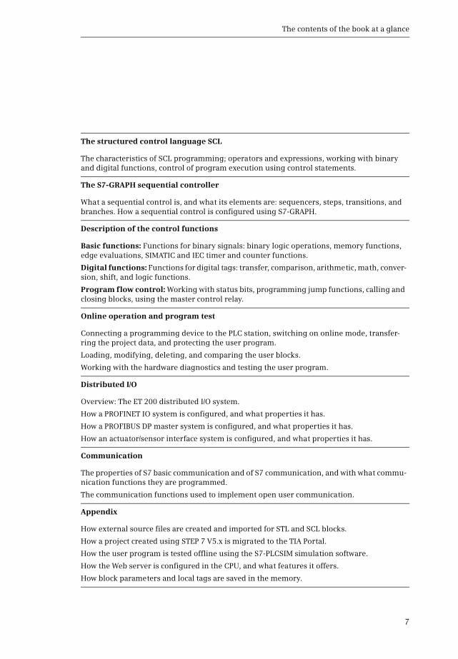
Table of contents
12
636 Editing tags 232637 Working with program comments 234
64 Programming a data block 236641 Creating a new data block 236642 Working area of program editor for data blocks 236643 Defining properties for data blocks 237644 Declaring data tags 238645 Entering data tags in global data blocks 239
65 Compiling blocks 239651 Starting the compilation 239652 Compiling SCL blocks 241653 Eliminating errors following compilation 241
66 Program information 242661 Cross-reference list 242662 Assignment list 244663 Call structure 245664 Dependency structure 246665 Consistency check 247666 Memory utilization of the CPU 248
7 Ladder logic LAD 249
71 Introduction 249711 Programming with LAD in general 249712 Program elements of ladder logic 251
72 Programming binary logic operations with LAD 252721 NO and NC contacts 252722 Series and parallel connection of contacts 253723 T branch open parallel branch 254724 Negating result of logic operation 255725 Edge evaluation of a binary tag 255726 Comparison contacts 256
73 Programming memory functions with LAD 257731 Simple coil assignment 257732 Set and reset coils 258733 Retentive response due to latching 259734 Coils with time response 260735 Coils with counter response 260
74 Programming Q boxes with LAD 261741 Memory boxes 261742 Edge evaluation of current flow 262743 SIMATIC timer functions 263744 SIMATIC counter functions 264745 IEC timer functions 265746 IEC counter functions 266
75 Programming ENENO boxes with LAD 267751 Transfer function MOVE 268
Table of contents
13
752 Arithmetic functions 269753 Math functions 269754 Conversion functions 270755 Shift functions 272756 Word logic operations 272
76 Controlling the program flow with LAD 274761 Working with status bits in the ladder logic 274762 ENENO mechanism with LAD 276763 Jump functions 277764 Block functions 278765 Master Control Relay (MCR) 280
8 Function block diagram FBD 282
81 Introduction 282811 Programming with FBD in general 282812 Program elements of the function block diagram 284
82 Programming binary logic operations with FBD 285821 Scanning for signal states ldquo1rdquo and ldquo0rdquo 285822 Programming a binary logic operation in the function block diagram 286823 AND function 287824 OR function 287825 Exclusive OR function 288826 Combined binary logic operations negating result of logic operation 288827 T branch 289828 Edge evaluation of binary tags 289829 Comparison functions 290
83 Programming standard boxes with FBD 291831 Assign box 291832 Set and reset boxes 292833 Standard boxes with time response 293834 Standard boxes with counter response 294
84 Programming Q boxes with FBD 294841 Memory boxes 295842 Edge evaluation of result of logic operation 296843 SIMATIC timer functions 297844 SIMATIC counter functions 297845 IEC timer functions 298846 IEC counter functions 299
85 Programming ENENO boxes with FBD 300851 Transfer function MOVE 301852 Arithmetic functions 302853 Math functions 303854 Conversion functions 303855 Shift functions 305856 Word logic operations 306
Table of contents
14
86 Controlling the program flow with FBD 307861 Working with status bits in the function block diagram 308862 ENENO mechanism with FBD 309863 Jump functions 310864 Block functions 312865 Master Control Relay (MCR) 313
9 Statement list STL 315
91 Introduction 315911 Programming with STL in general 315912 Structure of an STL statement 316
92 Programming binary logic operations with STL 317921 Processing of a binary logic operation operation step 317922 Scanning for signal states ldquo1rdquo and ldquo0rdquo 319923 Programming a binary logic operation in the statement list 320924 AND function 321925 OR function 321926 Exclusive OR function 321927 Combined binary logic operations 322928 Control of result of logic operation 324
93 Programming memory functions with STL 325931 Assignment 326932 Setting and resetting 326933 Edge evaluation 327
94 Programming timer and counter functions with STL 328941 SIMATIC timer functions 328942 SIMATIC counter functions 330943 IEC timer functions 331944 IEC counter functions 332
95 Programming digital functions with STL 333951 Transfer functions 333952 Comparison functions 333953 Arithmetic functions 337954 Math functions 340955 Conversion functions 341956 Shift functions 342957 Word logic operations 345
96 Controlling the program flow with STL 347961 Working with status bits in the statement list 347962 ENENO mechanism with STL 349963 Jump functions 351964 Jump list 352965 Loop jump 353966 Block functions 354967 Master Control Relay (MCR) 356
Table of contents
15
97 Further STL functions 358971 Accumulator functions 358972 Adding of constants to accumulator 1 360973 Decrementing incrementing 361974 Null instructions 361
10 Structured Control Language SCL 363
101 Introduction to programming with SCL 3631011 Programming with SCL in general 3631012 SCL statements and operators 365
102 Programming binary logic operations with SCL 3671021 Scanning for signal states ldquo1rdquo and ldquo0rdquo 3671022 AND function 3681023 OR function 3691024 Exclusive OR function 3691025 Combined binary logic operations 3691026 Negating result of logic operation 370
103 Programming memory functions with SCL 3701031 Value assignment of a binary tag 3711032 Setting and resetting 3711033 Edge evaluation 371
104 Programming timer and counter functions with SCL 3721041 SIMATIC timer functions 3721042 SIMATIC counter functions 3731043 IEC timer functions 3741044 IEC counter functions 375
105 Programming digital functions with SCL 3751051 Transfer function value assignment of a digital tag 3761052 Comparison functions 3761053 Arithmetic functions 3771054 Math functions 3781055 Conversion functions 3791056 Shift functions 3801057 Word logic operations logic expression 381
106 Controlling the program flow with SCL 3821061 Working with the ENO tag 3821062 ENENO mechanism with SCL 3831063 Control statements 3851064 Block functions 394
11 S7-GRAPH sequential control 397
111 Introduction 3971111 What is a sequential control 3971112 Properties of a sequential control 3981113 Program for a sequential control quantity framework 3991114 Operating modes 399
Table of contents
16
1115 Procedure for configuration 400
112 Elements of a sequential control 4001121 Steps and transitions 4001122 Jumps in a sequential control 4021123 Branching of a sequencer 4021124 GRAPH-specific tags 4031125 Permanent instructions 4041126 Step and transition functions 4051127 Processing of actions 408
113 Configuring a sequential control 4141131 Programming the GRAPH function block 4141132 Configuring the sequencer structure 4151133 Programming steps and transitions 4171134 Programming permanent instructions 4181135 Configuring block-independent alarms 4191136 Attributes of the GRAPH function block 4191137 Using the GRAPH function block 420
114 Testing the sequential control 4221141 Loading the GRAPH function block 4221142 Settings for program testing 4221143 Using operating modes 4231144 Synchronization of a sequencer 4241145 Testing with program status 425
12 Basic functions 427
121 Binary logic operations 4271211 Introduction 4271212 Working with binary signals 4281213 AND function series connection 4311214 OR function parallel connection 4321215 Exclusive OR function non-equivalence function 4321216 Negate result of logic operation NOT contact 433
122 Memory functions 4351221 Introduction 4351222 Standard coil assignment 4351223 Single setting and resetting 4361224 Dominant setting and resetting memory function 4371225 Edge evaluation 438
123 SIMATIC timer functions 4431231 Overview 4431232 Programming a timer function 4441233 Timer response as pulse 4491234 Timer response as extended pulse 4511235 Timer response as ON delay 4531236 Timer response as retentive ON delay 4551237 Timer response as OFF delay 457
Table of contents
17
124 IEC timer functions 4591241 Introduction 4591242 Pulse generation TP 4591243 ON delay TON 4601244 OFF delay TOF 461
125 SIMATIC counter functions 4621251 Overview 4621252 Programming a counter function 4631253 Principle of operation of a counter function 4671254 Enabling a counter function with STL 468
126 IEC counter functions 4701261 Introduction 4701262 Up counter CTU 4701263 Down counter CTD 4711264 Updown counter CTUD 472
13 Digital functions 475
131 General information 475
132 Transfer functions 4761321 General information on the ldquosimplerdquo transfer function 4761322 MOVE box with LAD and FBD 4761323 Loading and transferring with STL 4781324 Value assignments with SCL 4791325 Copying and filling a data area in the work memory 4811326 Transfer data area from and to load memory 4831327 Control memory area with MCR dependency 485
133 Comparison functions 4871331 Execution of ldquosimplerdquo comparison function 4881332 Comparison function T_COMP 4881333 Comparison function S_COMP 490
134 Arithmetic functions 4911341 General function description 4911342 Data types and status bits for an arithmetic function 4931343 Execution of the arithmetic function 4941344 Arithmetic functions for date and time 495
135 Math functions 4961351 General function description 4961352 General execution of a math function 4971353 Trigonometric functions SIN COS TAN 4981354 Arc functions ASIN ACOS ATAN 4991355 Additional math functions 499
136 Conversion functions 5001361 Implicit data type conversion 5011362 Data type conversion of fixed-point numbers 5011363 Data type conversion of floating-point numbers 5051364 Data type conversion for datetime with T_CONV 507
Table of contents
18
1365 Data type conversion for data type STRING with S_CONV 5091366 Data type conversion of hexadecimal numbers 5101367 Scaling and unscaling 5111368 Further conversion functions 513
137 Shift functions 5141371 General function description 5141372 General execution of a shift function 5141373 Shift to right 5161374 Shift to left 5171375 Rotate to right 5181376 Rotate to left 5181377 Rotating by the condition code bit CC1 (STL) 519
138 Logic functions 5191381 Word logic operations 5191382 Invert 5221383 Code bit and set bit number 5231384 Selection and limiting functions 524
139 Functions for strings 526
14 Program flow control 530
141 Status bits 5311411 Description of the status bits 5311412 Controlling the status bits 5331413 Setting and resetting the result of logic operation 5341414 Controlling the binary result 5351415 Evaluating the status bits 538
142 Jump functions 5391421 Introduction 5391422 Absolute jump 5391423 Conditional jump functions 5411424 Jump functions depending on status bits 542
143 Block end functions 5451431 Block end function RET (LAD and FBD) 5451432 Block end functions BEC BEU and BE (STL) 5461433 RETURN statement (SCL) 546
144 Calling of code blocks 5471441 General information on block calls 5471442 Calling a function (FC) 5471443 Calling a function block (FB) 5491444 Change to a block without block parameter 551
145 Data block functions 5531451 Open data block 5551452 Additional data block functions with STL 5551453 Creating deleting and testing data blocks 556
146 Master control relay 5601461 Introduction 560
Table of contents
19
1462 MCR dependency 5601463 MCR area and MCR zone 5601464 MCR area and MCR zone with a block change 5631465 Instructions for the master control relay 563
15 Online operation and program test 564
151 Connection of a programming device to the PLC station 5651511 Settings on the programming device 5651512 Connecting the programming device to the PLC station 5661513 Switching on online mode 566
152 Transferring project data 5681521 Loading project data for the first time 5681522 Reloading the project data 5701523 Protection of the user program 5711524 Editing of online project without offline project 5721525 Working with the Micro Memory Card 573
153 Working with blocks in online mode 5741531 Introduction 5741532 Editing the online version of a block 5751533 Downloading a block to the CPU 5751534 Packing the work memory 5771535 Uploading blocks from the CPU 5771536 Working with setpoints 5791537 Comparing blocks 581
154 Hardware diagnostics 5831541 Status displays on the modules 5831542 Diagnostic information 5841543 Diagnostic buffer 5851544 Diagnostic functions 5861545 Online tools 5861546 Further diagnostic information via the programming device 587
155 Testing the user program 5881551 Defining the call environment 5891552 Testing with program status 5891553 Testing in single step mode 5931554 Monitoring of PLC tags 5961555 Monitoring of data tags 5961556 Testing with watch tables 5971557 Monitoring and modifying in the STOP operating state 6021558 Testing with the force table 603
16 Distributed IO 607
161 Introduction overview 607
162 ET 200 distributed IO system 6081621 ET 200M 6081622 ET 200MP 609
Table of contents
20
1623 ET 200S 6091624 ET 200SP 6101625 ET 200iSP 6111626 ET 200pro 6111627 ET 200eco and ET 200eco PN 612
163 PROFINET IO 6131631 PROFINET IO components 6131632 Addresses with PROFINET IO 6151633 Special PROFINET configurations 6181634 Configuring PROFINET IO 6191635 Coupling modules for PROFINET IO 6231636 Real-time communication in PROFINET 624
164 PROFIBUS DP 6281641 PROFIBUS DP components 6281642 Addresses with PROFIBUS DP 6321643 Configuring PROFIBUS DP 6351644 Coupling modules for PROFIBUS DP 6381645 Special functions for PROFIBUS DP 640
165 Isochronous mode 6411651 Introduction 6411652 Isochronous mode with PROFINET IO 6411653 Isochronous mode with PROFIBUS 645
166 System blocks for distributed IO 6481661 System blocks for PROFIBUS DP 6481662 System blocks for PROFIBUS DP and PROFINET IO 6521663 System blocks for PROFINET IO 655
167 Actuatorsensor interface 6571671 Components of actuatorsensor interface 6571672 Addresses on the actuatorsensor interface 6601673 Configuring the actuatorsensor interface with CP 343-2P 6601674 System functions for AS-i 661
17 Communication 663
171 Overview 663
172 S7 basic communication 6641721 Basics of station-internal S7 basic communication 6641722 Configuring of station-internal S7 basic communication 6651723 System blocks for station-internal S7 basic communication 6651724 Basics of station-external S7 basic communication 6671725 Configuring of station-external S7 basic communication 6681726 System blocks for station-external S7 basic communication 668
173 S7 communication 6711731 Basics 6711732 Configuring S7 communication 6711733 One-way data exchange 674
Table of contents
21
1734 Two-way data exchange 6751735 Monitoring functions 678
174 Open user communication 6781741 Basics 6781742 Establishing and clearing connections 6801743 Data transfer with TCP native or ISO-on-TCP 6821744 Data transfer with UDP 685
18 Appendix 687
181 Working with source files 6871811 General procedure 6871812 Programming a code block in the source file 6881813 Programming a data block in the source file 6921814 Programming a PLC data type in the source file 695
182 Migrating projects 696183 Simulation with the TIA Portal 700
1831 Differences from a real CPU 7001832 Starting and saving the simulation 7011833 Using the simulation 7021834 Testing the program with the simulation 7051835 Additional functions of PLCSIM 707
184 Web server 7071841 Enable Web server 7071842 Reading out Web information 7081843 Standard Web pages 709
185 Storage of local tags 7121851 Storage in global data blocks 7121852 Storage in instance data blocks 7131853 Storage in the temporary local data 7131854 Data storage of the block parameters of a function (FC) 7151855 Data storage of the block parameters of a function block (FB) 7171856 Data storage of a local instance in a multi-instance 718
Index 721
1 Introduction
22
1 Introduction
11 Overview of the S7-300 automation system
SIMATIC S7-300 is the modular mini PLC system for the lower and medium perfor-mance ranges (Fig 11) Different versions of the controllers allow the performanceto be matched to the respective application Depending on the requirements theprogrammable controller can be expanded by inputoutput modules for digital andanalog signals in up to four racks with eight modules each
Further expansion with inputoutput modules is made possible by the distributedIO over PROFIBUS or PROFINET Special designs of these modules for increased me-chanical demands allow their installation directly on site on the machine or plantSTEP 7 is used to configure and program the SIMATIC S7-300 controllers Data ex-change between the controllers the distributed IO and the programming deviceis carried out over SIMATIC NET
Fig 11 Components of the SIMATIC S7-300 automation system
SIMATIC controllers controlthe machine or plant
The distributed IO expands theinterface to the machine or plant
SIMATIC NET
SIMATIC DP STEP 7Professional V12
SIMATIC S7-300
Networking allowsand central online access
data exchange
Several versions of the controllersexpand the range of use
STEP 7 is the engineering softwarefor configuring and programming
SIMATIC S7-300 automation system
11 Overview of the S7-300 automation system
23
111 SIMATIC S7-300 programmable controller
The most important components of an S7-300 programmable controller are shownin Fig 12
The CPU contains the operating system and the user program The user program issaved powerfail-proof on the Micro Memory Card (MMC) which is inserted in theCPU The user program is executed in the CPUs work memory The bus interfacespresent on the CPU establish the connection to other programmable controllers
Signal modules (SM) are responsible for the connection to the controlled plantThese input and output modules are available for digital and analog signals
The function modules (FM) are signal-preprocessing ldquointelligentrdquo IO moduleswhich prepare signals coming from the process independent of the CPU and eitherreturn them directly to the process or make them available at the CPUs internal in-terface Function modules are responsible for handling functions which the CPUcannot usually execute quickly enough such as counting pulses positioning orcontrolling drives
The CP modules allow data transfer in excess of the possibilities provided by thestandard interfaces with regard to protocols and communication functions
In the case of an expansion the interface modules (IM) connect the central rackto a maximum of three expansion racks
Finally a power supply module provides the voltage required by the programma-ble controller
Fig 12 Components of an S7-300 controller
Expansion rack
Central rack SM modules
FM modules
CP modules
IM module
IM moduleCPU module
PS module
Rack
Components of an S7-300 controller
1 Introduction
24
112 Overview of STEP 7 Professional V12
STEP 7 is the central automation tool for SIMATIC STEP 7 requires authorization(licensing) and is executed on the current Microsoft Windows operating systemsConfiguration of an S7-300 controller is carried out in two views the Portal viewand the Project view
The Portal view is task-oriented
In the Start portal you can open an existing project create a new project or migratea project A ldquoprojectrdquo is a data structure containing all the programs and data re-quired for your automation task The most important STEP 7 tools and functionscan be accessed from here via further portals (Fig 13)
b In the Devices amp networks portal you configure the programmable controllersie you position the modules in a rack and set their parameters
b In the PLC programming portal you create the user program in the form of indi-vidual sections referred to as ldquoblocksrdquo
b The Visualization portal provides the most important tools for configuration andsimulation of HMI systems using SIMATIC WinCC
b In the Motion amp Technology portal you insert a technology object for PID Controland edit it
Fig 13 Tools in the Start portal of STEP 7 Professional V12
11 Overview of the S7-300 automation system
25
b The Online amp Diagnostics portal allows you to connect the programming deviceonline to a CPU You can control the CPUs operating modes and transfer and testthe user program
The Project view is an object-oriented view with several windows whose contentschange depending on the current activity In the Device configuration the focalpoint is the working area with the device to be configured The Device view in-cludes the rack and the modules which have already been positioned (Fig 14) Afurther window ndash the inspector window ndash displays the properties of the selectedmodule and the task card provides support by means of the hardware catalog withthe available modules The Network view allows networking between PLC and HMIstations
When carrying out PLC programming you edit the selected block in the workingarea You are again shown the properties of the selected object in the inspector win-dow where you can adjust them In this case the task card contains the programelements catalog with the available program elements and instructions The sameapplies to the processing of PLC tags or to online program testing using watch ta-bles
Fig 14 Example of a Project view working area of the device configuration
1 Introduction
26
And you always have a view of the project tree This contains all objects of the STEP 7project You can therefore select an object at any time for example a program blockor watch table and edit this object using the corresponding editors which start au-tomatically when the object is opened
113 Five programming languages
You can select between five programming languages for the user program ladderlogic (LAD) function block diagram (FBD) statement list (STL) structured controllanguage (SCL) and sequential control (GRAPH)
Using the ladder logic you program the control task based on the circuit diagramOperations on binary signal states are represented by serial or parallel arrange-ment of contacts and coils (Fig 15) Complex functions such as arithmetic func-tions are represented by boxes which you arrange like contacts or coils in the ladderlogic
Using the function block diagram you program the control task based on electroniccircuitry systems Binary operations are implemented by linking AND and OR func-tions and are terminated by memory boxes (Fig 16) Complex boxes are used to han-dle the operations on digital tags for example with arithmetic functions
Fig 15 Example of representation in ladder logic
Fig 16 Example of representation in function block diagram
11 Overview of the S7-300 automation system
27
Using the statement list you program the control task using a sequence of state-ments Every STL statement contains the specification of what has to be done andpossibly an operand with which the operation is executed STL is equally suitable forbinary and digital operations and for programming complex open-loop control tasks(Fig 17)
Fig 17 Example of STL statements
Fig 18 Example of SCL statements
Fig 19 Example of a GRAPH sequencer and step configuration
1 Introduction
28
Structured control language is particularly suitable for programming complex al-gorithms or for tasks in the area of data management The program is made up of SCLstatements which for example can be value assignments comparisons or controlstatements (Fig 18)
Using GRAPH you program a control task as a sequential control in which a se-quence of actions prevails The individual steps and branches are enabled by step en-abling conditions which can be programmed using LAD or FBD (Fig 19)
114 Execution of the user program
After the power supply has been switched on the control processor checks the con-sistency of the hardware and parameterizes the modules A startup program is thenexecuted once if present The startup program belongs to the user program whichyou produce Modules can be initialized for example by the startup program
The user program is usually divided into individual sections called ldquoblocksrdquo Orga-nization blocks (OB) represent the interface between operating system and userprogram The operating system calls an organization block for specific events andthe user program is then processed in it (Fig 110)
Function blocks (FB) and functions (FC) are available for structuring the programFunction blocks have a memory in which local tags are saved permanently func-tions do not have this memory
Fig 110 Execution of the user program
Startupprogram
Alarm and errorprogram
Mainprogram
Execution of the user program
Switching on
Updating of inputsand outputs
Interruption(alarm or error)
Operating modeSTARTUP
Operating system User program
Operating modeRUN
OB
OB
FBFC
FBFC
FBFC
FBFC
FBFC
FBFC
OB
Interruption
11 Overview of the S7-300 automation system
29
Program instructions are available for calling function blocks and functions (startof execution) Each block call can be assigned inputs and outputs referred to asldquoblock parametersrdquo During calling tags can be transferred with which the pro-gram in the block is to work In this manner a block can be repeatedly called with acertain function (eg addition of three tags) but with different parameters sets(eg for different calculations) (Fig 111)
The data of the user program is saved in data blocks (DB) Instance data blocks havea fixed assignment to a call of a function block and are the tag memory of the func-tion block Global data blocks contain data which is not assigned to any block
Following a startup the control processor updates the input and output signals inthe process images and calls the organization block OB 1 The main program ispresent here Structuring is also possible (and recommended) in the main pro-gram Once the main program has been processed the control processor returns tothe operating system retains (for example) communication with the programmingdevice updates the input and output signals and then recommences with execu-tion of the main program
Cyclic program execution is a feature of programmable logic controllers The userprogram is even executed if no actions are requested ldquofrom outsiderdquo eg if the con-trolled machine is not running This provides advantages when programmingFor example you program the ladder logic as if you were drawing a circuit diagramor program the function block diagram as if you were connecting electronic compo-nents Roughly speaking a programmable controller has a characteristic like forexample a contactor or relay control the many programmed operations are effec-tive quasi simultaneously ldquoin parallelrdquo
In addition to the cyclically executed main program it is possible to carry out inter-rupt-controlled program execution You must enable the corresponding interrupt
Fig 111 Example of two block calls with different tags in each case
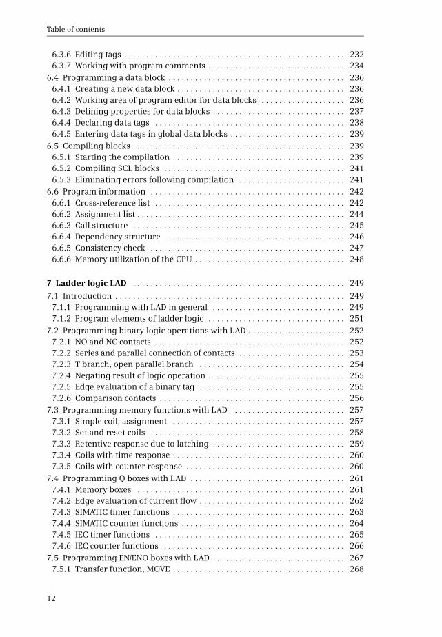
Table of contents
15
97 Further STL functions 358971 Accumulator functions 358972 Adding of constants to accumulator 1 360973 Decrementing incrementing 361974 Null instructions 361
10 Structured Control Language SCL 363
101 Introduction to programming with SCL 3631011 Programming with SCL in general 3631012 SCL statements and operators 365
102 Programming binary logic operations with SCL 3671021 Scanning for signal states ldquo1rdquo and ldquo0rdquo 3671022 AND function 3681023 OR function 3691024 Exclusive OR function 3691025 Combined binary logic operations 3691026 Negating result of logic operation 370
103 Programming memory functions with SCL 3701031 Value assignment of a binary tag 3711032 Setting and resetting 3711033 Edge evaluation 371
104 Programming timer and counter functions with SCL 3721041 SIMATIC timer functions 3721042 SIMATIC counter functions 3731043 IEC timer functions 3741044 IEC counter functions 375
105 Programming digital functions with SCL 3751051 Transfer function value assignment of a digital tag 3761052 Comparison functions 3761053 Arithmetic functions 3771054 Math functions 3781055 Conversion functions 3791056 Shift functions 3801057 Word logic operations logic expression 381
106 Controlling the program flow with SCL 3821061 Working with the ENO tag 3821062 ENENO mechanism with SCL 3831063 Control statements 3851064 Block functions 394
11 S7-GRAPH sequential control 397
111 Introduction 3971111 What is a sequential control 3971112 Properties of a sequential control 3981113 Program for a sequential control quantity framework 3991114 Operating modes 399
Table of contents
16
1115 Procedure for configuration 400
112 Elements of a sequential control 4001121 Steps and transitions 4001122 Jumps in a sequential control 4021123 Branching of a sequencer 4021124 GRAPH-specific tags 4031125 Permanent instructions 4041126 Step and transition functions 4051127 Processing of actions 408
113 Configuring a sequential control 4141131 Programming the GRAPH function block 4141132 Configuring the sequencer structure 4151133 Programming steps and transitions 4171134 Programming permanent instructions 4181135 Configuring block-independent alarms 4191136 Attributes of the GRAPH function block 4191137 Using the GRAPH function block 420
114 Testing the sequential control 4221141 Loading the GRAPH function block 4221142 Settings for program testing 4221143 Using operating modes 4231144 Synchronization of a sequencer 4241145 Testing with program status 425
12 Basic functions 427
121 Binary logic operations 4271211 Introduction 4271212 Working with binary signals 4281213 AND function series connection 4311214 OR function parallel connection 4321215 Exclusive OR function non-equivalence function 4321216 Negate result of logic operation NOT contact 433
122 Memory functions 4351221 Introduction 4351222 Standard coil assignment 4351223 Single setting and resetting 4361224 Dominant setting and resetting memory function 4371225 Edge evaluation 438
123 SIMATIC timer functions 4431231 Overview 4431232 Programming a timer function 4441233 Timer response as pulse 4491234 Timer response as extended pulse 4511235 Timer response as ON delay 4531236 Timer response as retentive ON delay 4551237 Timer response as OFF delay 457
Table of contents
17
124 IEC timer functions 4591241 Introduction 4591242 Pulse generation TP 4591243 ON delay TON 4601244 OFF delay TOF 461
125 SIMATIC counter functions 4621251 Overview 4621252 Programming a counter function 4631253 Principle of operation of a counter function 4671254 Enabling a counter function with STL 468
126 IEC counter functions 4701261 Introduction 4701262 Up counter CTU 4701263 Down counter CTD 4711264 Updown counter CTUD 472
13 Digital functions 475
131 General information 475
132 Transfer functions 4761321 General information on the ldquosimplerdquo transfer function 4761322 MOVE box with LAD and FBD 4761323 Loading and transferring with STL 4781324 Value assignments with SCL 4791325 Copying and filling a data area in the work memory 4811326 Transfer data area from and to load memory 4831327 Control memory area with MCR dependency 485
133 Comparison functions 4871331 Execution of ldquosimplerdquo comparison function 4881332 Comparison function T_COMP 4881333 Comparison function S_COMP 490
134 Arithmetic functions 4911341 General function description 4911342 Data types and status bits for an arithmetic function 4931343 Execution of the arithmetic function 4941344 Arithmetic functions for date and time 495
135 Math functions 4961351 General function description 4961352 General execution of a math function 4971353 Trigonometric functions SIN COS TAN 4981354 Arc functions ASIN ACOS ATAN 4991355 Additional math functions 499
136 Conversion functions 5001361 Implicit data type conversion 5011362 Data type conversion of fixed-point numbers 5011363 Data type conversion of floating-point numbers 5051364 Data type conversion for datetime with T_CONV 507
Table of contents
18
1365 Data type conversion for data type STRING with S_CONV 5091366 Data type conversion of hexadecimal numbers 5101367 Scaling and unscaling 5111368 Further conversion functions 513
137 Shift functions 5141371 General function description 5141372 General execution of a shift function 5141373 Shift to right 5161374 Shift to left 5171375 Rotate to right 5181376 Rotate to left 5181377 Rotating by the condition code bit CC1 (STL) 519
138 Logic functions 5191381 Word logic operations 5191382 Invert 5221383 Code bit and set bit number 5231384 Selection and limiting functions 524
139 Functions for strings 526
14 Program flow control 530
141 Status bits 5311411 Description of the status bits 5311412 Controlling the status bits 5331413 Setting and resetting the result of logic operation 5341414 Controlling the binary result 5351415 Evaluating the status bits 538
142 Jump functions 5391421 Introduction 5391422 Absolute jump 5391423 Conditional jump functions 5411424 Jump functions depending on status bits 542
143 Block end functions 5451431 Block end function RET (LAD and FBD) 5451432 Block end functions BEC BEU and BE (STL) 5461433 RETURN statement (SCL) 546
144 Calling of code blocks 5471441 General information on block calls 5471442 Calling a function (FC) 5471443 Calling a function block (FB) 5491444 Change to a block without block parameter 551
145 Data block functions 5531451 Open data block 5551452 Additional data block functions with STL 5551453 Creating deleting and testing data blocks 556
146 Master control relay 5601461 Introduction 560
Table of contents
19
1462 MCR dependency 5601463 MCR area and MCR zone 5601464 MCR area and MCR zone with a block change 5631465 Instructions for the master control relay 563
15 Online operation and program test 564
151 Connection of a programming device to the PLC station 5651511 Settings on the programming device 5651512 Connecting the programming device to the PLC station 5661513 Switching on online mode 566
152 Transferring project data 5681521 Loading project data for the first time 5681522 Reloading the project data 5701523 Protection of the user program 5711524 Editing of online project without offline project 5721525 Working with the Micro Memory Card 573
153 Working with blocks in online mode 5741531 Introduction 5741532 Editing the online version of a block 5751533 Downloading a block to the CPU 5751534 Packing the work memory 5771535 Uploading blocks from the CPU 5771536 Working with setpoints 5791537 Comparing blocks 581
154 Hardware diagnostics 5831541 Status displays on the modules 5831542 Diagnostic information 5841543 Diagnostic buffer 5851544 Diagnostic functions 5861545 Online tools 5861546 Further diagnostic information via the programming device 587
155 Testing the user program 5881551 Defining the call environment 5891552 Testing with program status 5891553 Testing in single step mode 5931554 Monitoring of PLC tags 5961555 Monitoring of data tags 5961556 Testing with watch tables 5971557 Monitoring and modifying in the STOP operating state 6021558 Testing with the force table 603
16 Distributed IO 607
161 Introduction overview 607
162 ET 200 distributed IO system 6081621 ET 200M 6081622 ET 200MP 609
Table of contents
20
1623 ET 200S 6091624 ET 200SP 6101625 ET 200iSP 6111626 ET 200pro 6111627 ET 200eco and ET 200eco PN 612
163 PROFINET IO 6131631 PROFINET IO components 6131632 Addresses with PROFINET IO 6151633 Special PROFINET configurations 6181634 Configuring PROFINET IO 6191635 Coupling modules for PROFINET IO 6231636 Real-time communication in PROFINET 624
164 PROFIBUS DP 6281641 PROFIBUS DP components 6281642 Addresses with PROFIBUS DP 6321643 Configuring PROFIBUS DP 6351644 Coupling modules for PROFIBUS DP 6381645 Special functions for PROFIBUS DP 640
165 Isochronous mode 6411651 Introduction 6411652 Isochronous mode with PROFINET IO 6411653 Isochronous mode with PROFIBUS 645
166 System blocks for distributed IO 6481661 System blocks for PROFIBUS DP 6481662 System blocks for PROFIBUS DP and PROFINET IO 6521663 System blocks for PROFINET IO 655
167 Actuatorsensor interface 6571671 Components of actuatorsensor interface 6571672 Addresses on the actuatorsensor interface 6601673 Configuring the actuatorsensor interface with CP 343-2P 6601674 System functions for AS-i 661
17 Communication 663
171 Overview 663
172 S7 basic communication 6641721 Basics of station-internal S7 basic communication 6641722 Configuring of station-internal S7 basic communication 6651723 System blocks for station-internal S7 basic communication 6651724 Basics of station-external S7 basic communication 6671725 Configuring of station-external S7 basic communication 6681726 System blocks for station-external S7 basic communication 668
173 S7 communication 6711731 Basics 6711732 Configuring S7 communication 6711733 One-way data exchange 674
Table of contents
21
1734 Two-way data exchange 6751735 Monitoring functions 678
174 Open user communication 6781741 Basics 6781742 Establishing and clearing connections 6801743 Data transfer with TCP native or ISO-on-TCP 6821744 Data transfer with UDP 685
18 Appendix 687
181 Working with source files 6871811 General procedure 6871812 Programming a code block in the source file 6881813 Programming a data block in the source file 6921814 Programming a PLC data type in the source file 695
182 Migrating projects 696183 Simulation with the TIA Portal 700
1831 Differences from a real CPU 7001832 Starting and saving the simulation 7011833 Using the simulation 7021834 Testing the program with the simulation 7051835 Additional functions of PLCSIM 707
184 Web server 7071841 Enable Web server 7071842 Reading out Web information 7081843 Standard Web pages 709
185 Storage of local tags 7121851 Storage in global data blocks 7121852 Storage in instance data blocks 7131853 Storage in the temporary local data 7131854 Data storage of the block parameters of a function (FC) 7151855 Data storage of the block parameters of a function block (FB) 7171856 Data storage of a local instance in a multi-instance 718
Index 721
1 Introduction
22
1 Introduction
11 Overview of the S7-300 automation system
SIMATIC S7-300 is the modular mini PLC system for the lower and medium perfor-mance ranges (Fig 11) Different versions of the controllers allow the performanceto be matched to the respective application Depending on the requirements theprogrammable controller can be expanded by inputoutput modules for digital andanalog signals in up to four racks with eight modules each
Further expansion with inputoutput modules is made possible by the distributedIO over PROFIBUS or PROFINET Special designs of these modules for increased me-chanical demands allow their installation directly on site on the machine or plantSTEP 7 is used to configure and program the SIMATIC S7-300 controllers Data ex-change between the controllers the distributed IO and the programming deviceis carried out over SIMATIC NET
Fig 11 Components of the SIMATIC S7-300 automation system
SIMATIC controllers controlthe machine or plant
The distributed IO expands theinterface to the machine or plant
SIMATIC NET
SIMATIC DP STEP 7Professional V12
SIMATIC S7-300
Networking allowsand central online access
data exchange
Several versions of the controllersexpand the range of use
STEP 7 is the engineering softwarefor configuring and programming
SIMATIC S7-300 automation system
11 Overview of the S7-300 automation system
23
111 SIMATIC S7-300 programmable controller
The most important components of an S7-300 programmable controller are shownin Fig 12
The CPU contains the operating system and the user program The user program issaved powerfail-proof on the Micro Memory Card (MMC) which is inserted in theCPU The user program is executed in the CPUs work memory The bus interfacespresent on the CPU establish the connection to other programmable controllers
Signal modules (SM) are responsible for the connection to the controlled plantThese input and output modules are available for digital and analog signals
The function modules (FM) are signal-preprocessing ldquointelligentrdquo IO moduleswhich prepare signals coming from the process independent of the CPU and eitherreturn them directly to the process or make them available at the CPUs internal in-terface Function modules are responsible for handling functions which the CPUcannot usually execute quickly enough such as counting pulses positioning orcontrolling drives
The CP modules allow data transfer in excess of the possibilities provided by thestandard interfaces with regard to protocols and communication functions
In the case of an expansion the interface modules (IM) connect the central rackto a maximum of three expansion racks
Finally a power supply module provides the voltage required by the programma-ble controller
Fig 12 Components of an S7-300 controller
Expansion rack
Central rack SM modules
FM modules
CP modules
IM module
IM moduleCPU module
PS module
Rack
Components of an S7-300 controller
1 Introduction
24
112 Overview of STEP 7 Professional V12
STEP 7 is the central automation tool for SIMATIC STEP 7 requires authorization(licensing) and is executed on the current Microsoft Windows operating systemsConfiguration of an S7-300 controller is carried out in two views the Portal viewand the Project view
The Portal view is task-oriented
In the Start portal you can open an existing project create a new project or migratea project A ldquoprojectrdquo is a data structure containing all the programs and data re-quired for your automation task The most important STEP 7 tools and functionscan be accessed from here via further portals (Fig 13)
b In the Devices amp networks portal you configure the programmable controllersie you position the modules in a rack and set their parameters
b In the PLC programming portal you create the user program in the form of indi-vidual sections referred to as ldquoblocksrdquo
b The Visualization portal provides the most important tools for configuration andsimulation of HMI systems using SIMATIC WinCC
b In the Motion amp Technology portal you insert a technology object for PID Controland edit it
Fig 13 Tools in the Start portal of STEP 7 Professional V12
11 Overview of the S7-300 automation system
25
b The Online amp Diagnostics portal allows you to connect the programming deviceonline to a CPU You can control the CPUs operating modes and transfer and testthe user program
The Project view is an object-oriented view with several windows whose contentschange depending on the current activity In the Device configuration the focalpoint is the working area with the device to be configured The Device view in-cludes the rack and the modules which have already been positioned (Fig 14) Afurther window ndash the inspector window ndash displays the properties of the selectedmodule and the task card provides support by means of the hardware catalog withthe available modules The Network view allows networking between PLC and HMIstations
When carrying out PLC programming you edit the selected block in the workingarea You are again shown the properties of the selected object in the inspector win-dow where you can adjust them In this case the task card contains the programelements catalog with the available program elements and instructions The sameapplies to the processing of PLC tags or to online program testing using watch ta-bles
Fig 14 Example of a Project view working area of the device configuration
1 Introduction
26
And you always have a view of the project tree This contains all objects of the STEP 7project You can therefore select an object at any time for example a program blockor watch table and edit this object using the corresponding editors which start au-tomatically when the object is opened
113 Five programming languages
You can select between five programming languages for the user program ladderlogic (LAD) function block diagram (FBD) statement list (STL) structured controllanguage (SCL) and sequential control (GRAPH)
Using the ladder logic you program the control task based on the circuit diagramOperations on binary signal states are represented by serial or parallel arrange-ment of contacts and coils (Fig 15) Complex functions such as arithmetic func-tions are represented by boxes which you arrange like contacts or coils in the ladderlogic
Using the function block diagram you program the control task based on electroniccircuitry systems Binary operations are implemented by linking AND and OR func-tions and are terminated by memory boxes (Fig 16) Complex boxes are used to han-dle the operations on digital tags for example with arithmetic functions
Fig 15 Example of representation in ladder logic
Fig 16 Example of representation in function block diagram
11 Overview of the S7-300 automation system
27
Using the statement list you program the control task using a sequence of state-ments Every STL statement contains the specification of what has to be done andpossibly an operand with which the operation is executed STL is equally suitable forbinary and digital operations and for programming complex open-loop control tasks(Fig 17)
Fig 17 Example of STL statements
Fig 18 Example of SCL statements
Fig 19 Example of a GRAPH sequencer and step configuration
1 Introduction
28
Structured control language is particularly suitable for programming complex al-gorithms or for tasks in the area of data management The program is made up of SCLstatements which for example can be value assignments comparisons or controlstatements (Fig 18)
Using GRAPH you program a control task as a sequential control in which a se-quence of actions prevails The individual steps and branches are enabled by step en-abling conditions which can be programmed using LAD or FBD (Fig 19)
114 Execution of the user program
After the power supply has been switched on the control processor checks the con-sistency of the hardware and parameterizes the modules A startup program is thenexecuted once if present The startup program belongs to the user program whichyou produce Modules can be initialized for example by the startup program
The user program is usually divided into individual sections called ldquoblocksrdquo Orga-nization blocks (OB) represent the interface between operating system and userprogram The operating system calls an organization block for specific events andthe user program is then processed in it (Fig 110)
Function blocks (FB) and functions (FC) are available for structuring the programFunction blocks have a memory in which local tags are saved permanently func-tions do not have this memory
Fig 110 Execution of the user program
Startupprogram
Alarm and errorprogram
Mainprogram
Execution of the user program
Switching on
Updating of inputsand outputs
Interruption(alarm or error)
Operating modeSTARTUP
Operating system User program
Operating modeRUN
OB
OB
FBFC
FBFC
FBFC
FBFC
FBFC
FBFC
OB
Interruption
11 Overview of the S7-300 automation system
29
Program instructions are available for calling function blocks and functions (startof execution) Each block call can be assigned inputs and outputs referred to asldquoblock parametersrdquo During calling tags can be transferred with which the pro-gram in the block is to work In this manner a block can be repeatedly called with acertain function (eg addition of three tags) but with different parameters sets(eg for different calculations) (Fig 111)
The data of the user program is saved in data blocks (DB) Instance data blocks havea fixed assignment to a call of a function block and are the tag memory of the func-tion block Global data blocks contain data which is not assigned to any block
Following a startup the control processor updates the input and output signals inthe process images and calls the organization block OB 1 The main program ispresent here Structuring is also possible (and recommended) in the main pro-gram Once the main program has been processed the control processor returns tothe operating system retains (for example) communication with the programmingdevice updates the input and output signals and then recommences with execu-tion of the main program
Cyclic program execution is a feature of programmable logic controllers The userprogram is even executed if no actions are requested ldquofrom outsiderdquo eg if the con-trolled machine is not running This provides advantages when programmingFor example you program the ladder logic as if you were drawing a circuit diagramor program the function block diagram as if you were connecting electronic compo-nents Roughly speaking a programmable controller has a characteristic like forexample a contactor or relay control the many programmed operations are effec-tive quasi simultaneously ldquoin parallelrdquo
In addition to the cyclically executed main program it is possible to carry out inter-rupt-controlled program execution You must enable the corresponding interrupt
Fig 111 Example of two block calls with different tags in each case
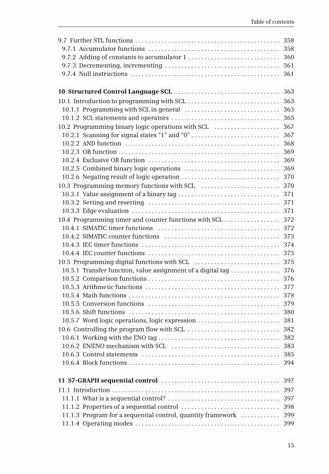
Table of contents
18
1365 Data type conversion for data type STRING with S_CONV 5091366 Data type conversion of hexadecimal numbers 5101367 Scaling and unscaling 5111368 Further conversion functions 513
137 Shift functions 5141371 General function description 5141372 General execution of a shift function 5141373 Shift to right 5161374 Shift to left 5171375 Rotate to right 5181376 Rotate to left 5181377 Rotating by the condition code bit CC1 (STL) 519
138 Logic functions 5191381 Word logic operations 5191382 Invert 5221383 Code bit and set bit number 5231384 Selection and limiting functions 524
139 Functions for strings 526
14 Program flow control 530
141 Status bits 5311411 Description of the status bits 5311412 Controlling the status bits 5331413 Setting and resetting the result of logic operation 5341414 Controlling the binary result 5351415 Evaluating the status bits 538
142 Jump functions 5391421 Introduction 5391422 Absolute jump 5391423 Conditional jump functions 5411424 Jump functions depending on status bits 542
143 Block end functions 5451431 Block end function RET (LAD and FBD) 5451432 Block end functions BEC BEU and BE (STL) 5461433 RETURN statement (SCL) 546
144 Calling of code blocks 5471441 General information on block calls 5471442 Calling a function (FC) 5471443 Calling a function block (FB) 5491444 Change to a block without block parameter 551
145 Data block functions 5531451 Open data block 5551452 Additional data block functions with STL 5551453 Creating deleting and testing data blocks 556
146 Master control relay 5601461 Introduction 560
Table of contents
19
1462 MCR dependency 5601463 MCR area and MCR zone 5601464 MCR area and MCR zone with a block change 5631465 Instructions for the master control relay 563
15 Online operation and program test 564
151 Connection of a programming device to the PLC station 5651511 Settings on the programming device 5651512 Connecting the programming device to the PLC station 5661513 Switching on online mode 566
152 Transferring project data 5681521 Loading project data for the first time 5681522 Reloading the project data 5701523 Protection of the user program 5711524 Editing of online project without offline project 5721525 Working with the Micro Memory Card 573
153 Working with blocks in online mode 5741531 Introduction 5741532 Editing the online version of a block 5751533 Downloading a block to the CPU 5751534 Packing the work memory 5771535 Uploading blocks from the CPU 5771536 Working with setpoints 5791537 Comparing blocks 581
154 Hardware diagnostics 5831541 Status displays on the modules 5831542 Diagnostic information 5841543 Diagnostic buffer 5851544 Diagnostic functions 5861545 Online tools 5861546 Further diagnostic information via the programming device 587
155 Testing the user program 5881551 Defining the call environment 5891552 Testing with program status 5891553 Testing in single step mode 5931554 Monitoring of PLC tags 5961555 Monitoring of data tags 5961556 Testing with watch tables 5971557 Monitoring and modifying in the STOP operating state 6021558 Testing with the force table 603
16 Distributed IO 607
161 Introduction overview 607
162 ET 200 distributed IO system 6081621 ET 200M 6081622 ET 200MP 609
Table of contents
20
1623 ET 200S 6091624 ET 200SP 6101625 ET 200iSP 6111626 ET 200pro 6111627 ET 200eco and ET 200eco PN 612
163 PROFINET IO 6131631 PROFINET IO components 6131632 Addresses with PROFINET IO 6151633 Special PROFINET configurations 6181634 Configuring PROFINET IO 6191635 Coupling modules for PROFINET IO 6231636 Real-time communication in PROFINET 624
164 PROFIBUS DP 6281641 PROFIBUS DP components 6281642 Addresses with PROFIBUS DP 6321643 Configuring PROFIBUS DP 6351644 Coupling modules for PROFIBUS DP 6381645 Special functions for PROFIBUS DP 640
165 Isochronous mode 6411651 Introduction 6411652 Isochronous mode with PROFINET IO 6411653 Isochronous mode with PROFIBUS 645
166 System blocks for distributed IO 6481661 System blocks for PROFIBUS DP 6481662 System blocks for PROFIBUS DP and PROFINET IO 6521663 System blocks for PROFINET IO 655
167 Actuatorsensor interface 6571671 Components of actuatorsensor interface 6571672 Addresses on the actuatorsensor interface 6601673 Configuring the actuatorsensor interface with CP 343-2P 6601674 System functions for AS-i 661
17 Communication 663
171 Overview 663
172 S7 basic communication 6641721 Basics of station-internal S7 basic communication 6641722 Configuring of station-internal S7 basic communication 6651723 System blocks for station-internal S7 basic communication 6651724 Basics of station-external S7 basic communication 6671725 Configuring of station-external S7 basic communication 6681726 System blocks for station-external S7 basic communication 668
173 S7 communication 6711731 Basics 6711732 Configuring S7 communication 6711733 One-way data exchange 674
Table of contents
21
1734 Two-way data exchange 6751735 Monitoring functions 678
174 Open user communication 6781741 Basics 6781742 Establishing and clearing connections 6801743 Data transfer with TCP native or ISO-on-TCP 6821744 Data transfer with UDP 685
18 Appendix 687
181 Working with source files 6871811 General procedure 6871812 Programming a code block in the source file 6881813 Programming a data block in the source file 6921814 Programming a PLC data type in the source file 695
182 Migrating projects 696183 Simulation with the TIA Portal 700
1831 Differences from a real CPU 7001832 Starting and saving the simulation 7011833 Using the simulation 7021834 Testing the program with the simulation 7051835 Additional functions of PLCSIM 707
184 Web server 7071841 Enable Web server 7071842 Reading out Web information 7081843 Standard Web pages 709
185 Storage of local tags 7121851 Storage in global data blocks 7121852 Storage in instance data blocks 7131853 Storage in the temporary local data 7131854 Data storage of the block parameters of a function (FC) 7151855 Data storage of the block parameters of a function block (FB) 7171856 Data storage of a local instance in a multi-instance 718
Index 721
1 Introduction
22
1 Introduction
11 Overview of the S7-300 automation system
SIMATIC S7-300 is the modular mini PLC system for the lower and medium perfor-mance ranges (Fig 11) Different versions of the controllers allow the performanceto be matched to the respective application Depending on the requirements theprogrammable controller can be expanded by inputoutput modules for digital andanalog signals in up to four racks with eight modules each
Further expansion with inputoutput modules is made possible by the distributedIO over PROFIBUS or PROFINET Special designs of these modules for increased me-chanical demands allow their installation directly on site on the machine or plantSTEP 7 is used to configure and program the SIMATIC S7-300 controllers Data ex-change between the controllers the distributed IO and the programming deviceis carried out over SIMATIC NET
Fig 11 Components of the SIMATIC S7-300 automation system
SIMATIC controllers controlthe machine or plant
The distributed IO expands theinterface to the machine or plant
SIMATIC NET
SIMATIC DP STEP 7Professional V12
SIMATIC S7-300
Networking allowsand central online access
data exchange
Several versions of the controllersexpand the range of use
STEP 7 is the engineering softwarefor configuring and programming
SIMATIC S7-300 automation system
11 Overview of the S7-300 automation system
23
111 SIMATIC S7-300 programmable controller
The most important components of an S7-300 programmable controller are shownin Fig 12
The CPU contains the operating system and the user program The user program issaved powerfail-proof on the Micro Memory Card (MMC) which is inserted in theCPU The user program is executed in the CPUs work memory The bus interfacespresent on the CPU establish the connection to other programmable controllers
Signal modules (SM) are responsible for the connection to the controlled plantThese input and output modules are available for digital and analog signals
The function modules (FM) are signal-preprocessing ldquointelligentrdquo IO moduleswhich prepare signals coming from the process independent of the CPU and eitherreturn them directly to the process or make them available at the CPUs internal in-terface Function modules are responsible for handling functions which the CPUcannot usually execute quickly enough such as counting pulses positioning orcontrolling drives
The CP modules allow data transfer in excess of the possibilities provided by thestandard interfaces with regard to protocols and communication functions
In the case of an expansion the interface modules (IM) connect the central rackto a maximum of three expansion racks
Finally a power supply module provides the voltage required by the programma-ble controller
Fig 12 Components of an S7-300 controller
Expansion rack
Central rack SM modules
FM modules
CP modules
IM module
IM moduleCPU module
PS module
Rack
Components of an S7-300 controller
1 Introduction
24
112 Overview of STEP 7 Professional V12
STEP 7 is the central automation tool for SIMATIC STEP 7 requires authorization(licensing) and is executed on the current Microsoft Windows operating systemsConfiguration of an S7-300 controller is carried out in two views the Portal viewand the Project view
The Portal view is task-oriented
In the Start portal you can open an existing project create a new project or migratea project A ldquoprojectrdquo is a data structure containing all the programs and data re-quired for your automation task The most important STEP 7 tools and functionscan be accessed from here via further portals (Fig 13)
b In the Devices amp networks portal you configure the programmable controllersie you position the modules in a rack and set their parameters
b In the PLC programming portal you create the user program in the form of indi-vidual sections referred to as ldquoblocksrdquo
b The Visualization portal provides the most important tools for configuration andsimulation of HMI systems using SIMATIC WinCC
b In the Motion amp Technology portal you insert a technology object for PID Controland edit it
Fig 13 Tools in the Start portal of STEP 7 Professional V12
11 Overview of the S7-300 automation system
25
b The Online amp Diagnostics portal allows you to connect the programming deviceonline to a CPU You can control the CPUs operating modes and transfer and testthe user program
The Project view is an object-oriented view with several windows whose contentschange depending on the current activity In the Device configuration the focalpoint is the working area with the device to be configured The Device view in-cludes the rack and the modules which have already been positioned (Fig 14) Afurther window ndash the inspector window ndash displays the properties of the selectedmodule and the task card provides support by means of the hardware catalog withthe available modules The Network view allows networking between PLC and HMIstations
When carrying out PLC programming you edit the selected block in the workingarea You are again shown the properties of the selected object in the inspector win-dow where you can adjust them In this case the task card contains the programelements catalog with the available program elements and instructions The sameapplies to the processing of PLC tags or to online program testing using watch ta-bles
Fig 14 Example of a Project view working area of the device configuration
1 Introduction
26
And you always have a view of the project tree This contains all objects of the STEP 7project You can therefore select an object at any time for example a program blockor watch table and edit this object using the corresponding editors which start au-tomatically when the object is opened
113 Five programming languages
You can select between five programming languages for the user program ladderlogic (LAD) function block diagram (FBD) statement list (STL) structured controllanguage (SCL) and sequential control (GRAPH)
Using the ladder logic you program the control task based on the circuit diagramOperations on binary signal states are represented by serial or parallel arrange-ment of contacts and coils (Fig 15) Complex functions such as arithmetic func-tions are represented by boxes which you arrange like contacts or coils in the ladderlogic
Using the function block diagram you program the control task based on electroniccircuitry systems Binary operations are implemented by linking AND and OR func-tions and are terminated by memory boxes (Fig 16) Complex boxes are used to han-dle the operations on digital tags for example with arithmetic functions
Fig 15 Example of representation in ladder logic
Fig 16 Example of representation in function block diagram
11 Overview of the S7-300 automation system
27
Using the statement list you program the control task using a sequence of state-ments Every STL statement contains the specification of what has to be done andpossibly an operand with which the operation is executed STL is equally suitable forbinary and digital operations and for programming complex open-loop control tasks(Fig 17)
Fig 17 Example of STL statements
Fig 18 Example of SCL statements
Fig 19 Example of a GRAPH sequencer and step configuration
1 Introduction
28
Structured control language is particularly suitable for programming complex al-gorithms or for tasks in the area of data management The program is made up of SCLstatements which for example can be value assignments comparisons or controlstatements (Fig 18)
Using GRAPH you program a control task as a sequential control in which a se-quence of actions prevails The individual steps and branches are enabled by step en-abling conditions which can be programmed using LAD or FBD (Fig 19)
114 Execution of the user program
After the power supply has been switched on the control processor checks the con-sistency of the hardware and parameterizes the modules A startup program is thenexecuted once if present The startup program belongs to the user program whichyou produce Modules can be initialized for example by the startup program
The user program is usually divided into individual sections called ldquoblocksrdquo Orga-nization blocks (OB) represent the interface between operating system and userprogram The operating system calls an organization block for specific events andthe user program is then processed in it (Fig 110)
Function blocks (FB) and functions (FC) are available for structuring the programFunction blocks have a memory in which local tags are saved permanently func-tions do not have this memory
Fig 110 Execution of the user program
Startupprogram
Alarm and errorprogram
Mainprogram
Execution of the user program
Switching on
Updating of inputsand outputs
Interruption(alarm or error)
Operating modeSTARTUP
Operating system User program
Operating modeRUN
OB
OB
FBFC
FBFC
FBFC
FBFC
FBFC
FBFC
OB
Interruption
11 Overview of the S7-300 automation system
29
Program instructions are available for calling function blocks and functions (startof execution) Each block call can be assigned inputs and outputs referred to asldquoblock parametersrdquo During calling tags can be transferred with which the pro-gram in the block is to work In this manner a block can be repeatedly called with acertain function (eg addition of three tags) but with different parameters sets(eg for different calculations) (Fig 111)
The data of the user program is saved in data blocks (DB) Instance data blocks havea fixed assignment to a call of a function block and are the tag memory of the func-tion block Global data blocks contain data which is not assigned to any block
Following a startup the control processor updates the input and output signals inthe process images and calls the organization block OB 1 The main program ispresent here Structuring is also possible (and recommended) in the main pro-gram Once the main program has been processed the control processor returns tothe operating system retains (for example) communication with the programmingdevice updates the input and output signals and then recommences with execu-tion of the main program
Cyclic program execution is a feature of programmable logic controllers The userprogram is even executed if no actions are requested ldquofrom outsiderdquo eg if the con-trolled machine is not running This provides advantages when programmingFor example you program the ladder logic as if you were drawing a circuit diagramor program the function block diagram as if you were connecting electronic compo-nents Roughly speaking a programmable controller has a characteristic like forexample a contactor or relay control the many programmed operations are effec-tive quasi simultaneously ldquoin parallelrdquo
In addition to the cyclically executed main program it is possible to carry out inter-rupt-controlled program execution You must enable the corresponding interrupt
Fig 111 Example of two block calls with different tags in each case
Table of contents
21
1734 Two-way data exchange 6751735 Monitoring functions 678
174 Open user communication 6781741 Basics 6781742 Establishing and clearing connections 6801743 Data transfer with TCP native or ISO-on-TCP 6821744 Data transfer with UDP 685
18 Appendix 687
181 Working with source files 6871811 General procedure 6871812 Programming a code block in the source file 6881813 Programming a data block in the source file 6921814 Programming a PLC data type in the source file 695
182 Migrating projects 696183 Simulation with the TIA Portal 700
1831 Differences from a real CPU 7001832 Starting and saving the simulation 7011833 Using the simulation 7021834 Testing the program with the simulation 7051835 Additional functions of PLCSIM 707
184 Web server 7071841 Enable Web server 7071842 Reading out Web information 7081843 Standard Web pages 709
185 Storage of local tags 7121851 Storage in global data blocks 7121852 Storage in instance data blocks 7131853 Storage in the temporary local data 7131854 Data storage of the block parameters of a function (FC) 7151855 Data storage of the block parameters of a function block (FB) 7171856 Data storage of a local instance in a multi-instance 718
Index 721
1 Introduction
22
1 Introduction
11 Overview of the S7-300 automation system
SIMATIC S7-300 is the modular mini PLC system for the lower and medium perfor-mance ranges (Fig 11) Different versions of the controllers allow the performanceto be matched to the respective application Depending on the requirements theprogrammable controller can be expanded by inputoutput modules for digital andanalog signals in up to four racks with eight modules each
Further expansion with inputoutput modules is made possible by the distributedIO over PROFIBUS or PROFINET Special designs of these modules for increased me-chanical demands allow their installation directly on site on the machine or plantSTEP 7 is used to configure and program the SIMATIC S7-300 controllers Data ex-change between the controllers the distributed IO and the programming deviceis carried out over SIMATIC NET
Fig 11 Components of the SIMATIC S7-300 automation system
SIMATIC controllers controlthe machine or plant
The distributed IO expands theinterface to the machine or plant
SIMATIC NET
SIMATIC DP STEP 7Professional V12
SIMATIC S7-300
Networking allowsand central online access
data exchange
Several versions of the controllersexpand the range of use
STEP 7 is the engineering softwarefor configuring and programming
SIMATIC S7-300 automation system
11 Overview of the S7-300 automation system
23
111 SIMATIC S7-300 programmable controller
The most important components of an S7-300 programmable controller are shownin Fig 12
The CPU contains the operating system and the user program The user program issaved powerfail-proof on the Micro Memory Card (MMC) which is inserted in theCPU The user program is executed in the CPUs work memory The bus interfacespresent on the CPU establish the connection to other programmable controllers
Signal modules (SM) are responsible for the connection to the controlled plantThese input and output modules are available for digital and analog signals
The function modules (FM) are signal-preprocessing ldquointelligentrdquo IO moduleswhich prepare signals coming from the process independent of the CPU and eitherreturn them directly to the process or make them available at the CPUs internal in-terface Function modules are responsible for handling functions which the CPUcannot usually execute quickly enough such as counting pulses positioning orcontrolling drives
The CP modules allow data transfer in excess of the possibilities provided by thestandard interfaces with regard to protocols and communication functions
In the case of an expansion the interface modules (IM) connect the central rackto a maximum of three expansion racks
Finally a power supply module provides the voltage required by the programma-ble controller
Fig 12 Components of an S7-300 controller
Expansion rack
Central rack SM modules
FM modules
CP modules
IM module
IM moduleCPU module
PS module
Rack
Components of an S7-300 controller
1 Introduction
24
112 Overview of STEP 7 Professional V12
STEP 7 is the central automation tool for SIMATIC STEP 7 requires authorization(licensing) and is executed on the current Microsoft Windows operating systemsConfiguration of an S7-300 controller is carried out in two views the Portal viewand the Project view
The Portal view is task-oriented
In the Start portal you can open an existing project create a new project or migratea project A ldquoprojectrdquo is a data structure containing all the programs and data re-quired for your automation task The most important STEP 7 tools and functionscan be accessed from here via further portals (Fig 13)
b In the Devices amp networks portal you configure the programmable controllersie you position the modules in a rack and set their parameters
b In the PLC programming portal you create the user program in the form of indi-vidual sections referred to as ldquoblocksrdquo
b The Visualization portal provides the most important tools for configuration andsimulation of HMI systems using SIMATIC WinCC
b In the Motion amp Technology portal you insert a technology object for PID Controland edit it
Fig 13 Tools in the Start portal of STEP 7 Professional V12
11 Overview of the S7-300 automation system
25
b The Online amp Diagnostics portal allows you to connect the programming deviceonline to a CPU You can control the CPUs operating modes and transfer and testthe user program
The Project view is an object-oriented view with several windows whose contentschange depending on the current activity In the Device configuration the focalpoint is the working area with the device to be configured The Device view in-cludes the rack and the modules which have already been positioned (Fig 14) Afurther window ndash the inspector window ndash displays the properties of the selectedmodule and the task card provides support by means of the hardware catalog withthe available modules The Network view allows networking between PLC and HMIstations
When carrying out PLC programming you edit the selected block in the workingarea You are again shown the properties of the selected object in the inspector win-dow where you can adjust them In this case the task card contains the programelements catalog with the available program elements and instructions The sameapplies to the processing of PLC tags or to online program testing using watch ta-bles
Fig 14 Example of a Project view working area of the device configuration
1 Introduction
26
And you always have a view of the project tree This contains all objects of the STEP 7project You can therefore select an object at any time for example a program blockor watch table and edit this object using the corresponding editors which start au-tomatically when the object is opened
113 Five programming languages
You can select between five programming languages for the user program ladderlogic (LAD) function block diagram (FBD) statement list (STL) structured controllanguage (SCL) and sequential control (GRAPH)
Using the ladder logic you program the control task based on the circuit diagramOperations on binary signal states are represented by serial or parallel arrange-ment of contacts and coils (Fig 15) Complex functions such as arithmetic func-tions are represented by boxes which you arrange like contacts or coils in the ladderlogic
Using the function block diagram you program the control task based on electroniccircuitry systems Binary operations are implemented by linking AND and OR func-tions and are terminated by memory boxes (Fig 16) Complex boxes are used to han-dle the operations on digital tags for example with arithmetic functions
Fig 15 Example of representation in ladder logic
Fig 16 Example of representation in function block diagram
11 Overview of the S7-300 automation system
27
Using the statement list you program the control task using a sequence of state-ments Every STL statement contains the specification of what has to be done andpossibly an operand with which the operation is executed STL is equally suitable forbinary and digital operations and for programming complex open-loop control tasks(Fig 17)
Fig 17 Example of STL statements
Fig 18 Example of SCL statements
Fig 19 Example of a GRAPH sequencer and step configuration
1 Introduction
28
Structured control language is particularly suitable for programming complex al-gorithms or for tasks in the area of data management The program is made up of SCLstatements which for example can be value assignments comparisons or controlstatements (Fig 18)
Using GRAPH you program a control task as a sequential control in which a se-quence of actions prevails The individual steps and branches are enabled by step en-abling conditions which can be programmed using LAD or FBD (Fig 19)
114 Execution of the user program
After the power supply has been switched on the control processor checks the con-sistency of the hardware and parameterizes the modules A startup program is thenexecuted once if present The startup program belongs to the user program whichyou produce Modules can be initialized for example by the startup program
The user program is usually divided into individual sections called ldquoblocksrdquo Orga-nization blocks (OB) represent the interface between operating system and userprogram The operating system calls an organization block for specific events andthe user program is then processed in it (Fig 110)
Function blocks (FB) and functions (FC) are available for structuring the programFunction blocks have a memory in which local tags are saved permanently func-tions do not have this memory
Fig 110 Execution of the user program
Startupprogram
Alarm and errorprogram
Mainprogram
Execution of the user program
Switching on
Updating of inputsand outputs
Interruption(alarm or error)
Operating modeSTARTUP
Operating system User program
Operating modeRUN
OB
OB
FBFC
FBFC
FBFC
FBFC
FBFC
FBFC
OB
Interruption
11 Overview of the S7-300 automation system
29
Program instructions are available for calling function blocks and functions (startof execution) Each block call can be assigned inputs and outputs referred to asldquoblock parametersrdquo During calling tags can be transferred with which the pro-gram in the block is to work In this manner a block can be repeatedly called with acertain function (eg addition of three tags) but with different parameters sets(eg for different calculations) (Fig 111)
The data of the user program is saved in data blocks (DB) Instance data blocks havea fixed assignment to a call of a function block and are the tag memory of the func-tion block Global data blocks contain data which is not assigned to any block
Following a startup the control processor updates the input and output signals inthe process images and calls the organization block OB 1 The main program ispresent here Structuring is also possible (and recommended) in the main pro-gram Once the main program has been processed the control processor returns tothe operating system retains (for example) communication with the programmingdevice updates the input and output signals and then recommences with execu-tion of the main program
Cyclic program execution is a feature of programmable logic controllers The userprogram is even executed if no actions are requested ldquofrom outsiderdquo eg if the con-trolled machine is not running This provides advantages when programmingFor example you program the ladder logic as if you were drawing a circuit diagramor program the function block diagram as if you were connecting electronic compo-nents Roughly speaking a programmable controller has a characteristic like forexample a contactor or relay control the many programmed operations are effec-tive quasi simultaneously ldquoin parallelrdquo
In addition to the cyclically executed main program it is possible to carry out inter-rupt-controlled program execution You must enable the corresponding interrupt
Fig 111 Example of two block calls with different tags in each case

1 Introduction
22
1 Introduction
11 Overview of the S7-300 automation system
SIMATIC S7-300 is the modular mini PLC system for the lower and medium perfor-mance ranges (Fig 11) Different versions of the controllers allow the performanceto be matched to the respective application Depending on the requirements theprogrammable controller can be expanded by inputoutput modules for digital andanalog signals in up to four racks with eight modules each
Further expansion with inputoutput modules is made possible by the distributedIO over PROFIBUS or PROFINET Special designs of these modules for increased me-chanical demands allow their installation directly on site on the machine or plantSTEP 7 is used to configure and program the SIMATIC S7-300 controllers Data ex-change between the controllers the distributed IO and the programming deviceis carried out over SIMATIC NET
Fig 11 Components of the SIMATIC S7-300 automation system
SIMATIC controllers controlthe machine or plant
The distributed IO expands theinterface to the machine or plant
SIMATIC NET
SIMATIC DP STEP 7Professional V12
SIMATIC S7-300
Networking allowsand central online access
data exchange
Several versions of the controllersexpand the range of use
STEP 7 is the engineering softwarefor configuring and programming
SIMATIC S7-300 automation system
11 Overview of the S7-300 automation system
23
111 SIMATIC S7-300 programmable controller
The most important components of an S7-300 programmable controller are shownin Fig 12
The CPU contains the operating system and the user program The user program issaved powerfail-proof on the Micro Memory Card (MMC) which is inserted in theCPU The user program is executed in the CPUs work memory The bus interfacespresent on the CPU establish the connection to other programmable controllers
Signal modules (SM) are responsible for the connection to the controlled plantThese input and output modules are available for digital and analog signals
The function modules (FM) are signal-preprocessing ldquointelligentrdquo IO moduleswhich prepare signals coming from the process independent of the CPU and eitherreturn them directly to the process or make them available at the CPUs internal in-terface Function modules are responsible for handling functions which the CPUcannot usually execute quickly enough such as counting pulses positioning orcontrolling drives
The CP modules allow data transfer in excess of the possibilities provided by thestandard interfaces with regard to protocols and communication functions
In the case of an expansion the interface modules (IM) connect the central rackto a maximum of three expansion racks
Finally a power supply module provides the voltage required by the programma-ble controller
Fig 12 Components of an S7-300 controller
Expansion rack
Central rack SM modules
FM modules
CP modules
IM module
IM moduleCPU module
PS module
Rack
Components of an S7-300 controller
1 Introduction
24
112 Overview of STEP 7 Professional V12
STEP 7 is the central automation tool for SIMATIC STEP 7 requires authorization(licensing) and is executed on the current Microsoft Windows operating systemsConfiguration of an S7-300 controller is carried out in two views the Portal viewand the Project view
The Portal view is task-oriented
In the Start portal you can open an existing project create a new project or migratea project A ldquoprojectrdquo is a data structure containing all the programs and data re-quired for your automation task The most important STEP 7 tools and functionscan be accessed from here via further portals (Fig 13)
b In the Devices amp networks portal you configure the programmable controllersie you position the modules in a rack and set their parameters
b In the PLC programming portal you create the user program in the form of indi-vidual sections referred to as ldquoblocksrdquo
b The Visualization portal provides the most important tools for configuration andsimulation of HMI systems using SIMATIC WinCC
b In the Motion amp Technology portal you insert a technology object for PID Controland edit it
Fig 13 Tools in the Start portal of STEP 7 Professional V12
11 Overview of the S7-300 automation system
25
b The Online amp Diagnostics portal allows you to connect the programming deviceonline to a CPU You can control the CPUs operating modes and transfer and testthe user program
The Project view is an object-oriented view with several windows whose contentschange depending on the current activity In the Device configuration the focalpoint is the working area with the device to be configured The Device view in-cludes the rack and the modules which have already been positioned (Fig 14) Afurther window ndash the inspector window ndash displays the properties of the selectedmodule and the task card provides support by means of the hardware catalog withthe available modules The Network view allows networking between PLC and HMIstations
When carrying out PLC programming you edit the selected block in the workingarea You are again shown the properties of the selected object in the inspector win-dow where you can adjust them In this case the task card contains the programelements catalog with the available program elements and instructions The sameapplies to the processing of PLC tags or to online program testing using watch ta-bles
Fig 14 Example of a Project view working area of the device configuration
1 Introduction
26
And you always have a view of the project tree This contains all objects of the STEP 7project You can therefore select an object at any time for example a program blockor watch table and edit this object using the corresponding editors which start au-tomatically when the object is opened
113 Five programming languages
You can select between five programming languages for the user program ladderlogic (LAD) function block diagram (FBD) statement list (STL) structured controllanguage (SCL) and sequential control (GRAPH)
Using the ladder logic you program the control task based on the circuit diagramOperations on binary signal states are represented by serial or parallel arrange-ment of contacts and coils (Fig 15) Complex functions such as arithmetic func-tions are represented by boxes which you arrange like contacts or coils in the ladderlogic
Using the function block diagram you program the control task based on electroniccircuitry systems Binary operations are implemented by linking AND and OR func-tions and are terminated by memory boxes (Fig 16) Complex boxes are used to han-dle the operations on digital tags for example with arithmetic functions
Fig 15 Example of representation in ladder logic
Fig 16 Example of representation in function block diagram
11 Overview of the S7-300 automation system
27
Using the statement list you program the control task using a sequence of state-ments Every STL statement contains the specification of what has to be done andpossibly an operand with which the operation is executed STL is equally suitable forbinary and digital operations and for programming complex open-loop control tasks(Fig 17)
Fig 17 Example of STL statements
Fig 18 Example of SCL statements
Fig 19 Example of a GRAPH sequencer and step configuration
1 Introduction
28
Structured control language is particularly suitable for programming complex al-gorithms or for tasks in the area of data management The program is made up of SCLstatements which for example can be value assignments comparisons or controlstatements (Fig 18)
Using GRAPH you program a control task as a sequential control in which a se-quence of actions prevails The individual steps and branches are enabled by step en-abling conditions which can be programmed using LAD or FBD (Fig 19)
114 Execution of the user program
After the power supply has been switched on the control processor checks the con-sistency of the hardware and parameterizes the modules A startup program is thenexecuted once if present The startup program belongs to the user program whichyou produce Modules can be initialized for example by the startup program
The user program is usually divided into individual sections called ldquoblocksrdquo Orga-nization blocks (OB) represent the interface between operating system and userprogram The operating system calls an organization block for specific events andthe user program is then processed in it (Fig 110)
Function blocks (FB) and functions (FC) are available for structuring the programFunction blocks have a memory in which local tags are saved permanently func-tions do not have this memory
Fig 110 Execution of the user program
Startupprogram
Alarm and errorprogram
Mainprogram
Execution of the user program
Switching on
Updating of inputsand outputs
Interruption(alarm or error)
Operating modeSTARTUP
Operating system User program
Operating modeRUN
OB
OB
FBFC
FBFC
FBFC
FBFC
FBFC
FBFC
OB
Interruption
11 Overview of the S7-300 automation system
29
Program instructions are available for calling function blocks and functions (startof execution) Each block call can be assigned inputs and outputs referred to asldquoblock parametersrdquo During calling tags can be transferred with which the pro-gram in the block is to work In this manner a block can be repeatedly called with acertain function (eg addition of three tags) but with different parameters sets(eg for different calculations) (Fig 111)
The data of the user program is saved in data blocks (DB) Instance data blocks havea fixed assignment to a call of a function block and are the tag memory of the func-tion block Global data blocks contain data which is not assigned to any block
Following a startup the control processor updates the input and output signals inthe process images and calls the organization block OB 1 The main program ispresent here Structuring is also possible (and recommended) in the main pro-gram Once the main program has been processed the control processor returns tothe operating system retains (for example) communication with the programmingdevice updates the input and output signals and then recommences with execu-tion of the main program
Cyclic program execution is a feature of programmable logic controllers The userprogram is even executed if no actions are requested ldquofrom outsiderdquo eg if the con-trolled machine is not running This provides advantages when programmingFor example you program the ladder logic as if you were drawing a circuit diagramor program the function block diagram as if you were connecting electronic compo-nents Roughly speaking a programmable controller has a characteristic like forexample a contactor or relay control the many programmed operations are effec-tive quasi simultaneously ldquoin parallelrdquo
In addition to the cyclically executed main program it is possible to carry out inter-rupt-controlled program execution You must enable the corresponding interrupt
Fig 111 Example of two block calls with different tags in each case

11 Overview of the S7-300 automation system
23
111 SIMATIC S7-300 programmable controller
The most important components of an S7-300 programmable controller are shownin Fig 12
The CPU contains the operating system and the user program The user program issaved powerfail-proof on the Micro Memory Card (MMC) which is inserted in theCPU The user program is executed in the CPUs work memory The bus interfacespresent on the CPU establish the connection to other programmable controllers
Signal modules (SM) are responsible for the connection to the controlled plantThese input and output modules are available for digital and analog signals
The function modules (FM) are signal-preprocessing ldquointelligentrdquo IO moduleswhich prepare signals coming from the process independent of the CPU and eitherreturn them directly to the process or make them available at the CPUs internal in-terface Function modules are responsible for handling functions which the CPUcannot usually execute quickly enough such as counting pulses positioning orcontrolling drives
The CP modules allow data transfer in excess of the possibilities provided by thestandard interfaces with regard to protocols and communication functions
In the case of an expansion the interface modules (IM) connect the central rackto a maximum of three expansion racks
Finally a power supply module provides the voltage required by the programma-ble controller
Fig 12 Components of an S7-300 controller
Expansion rack
Central rack SM modules
FM modules
CP modules
IM module
IM moduleCPU module
PS module
Rack
Components of an S7-300 controller
1 Introduction
24
112 Overview of STEP 7 Professional V12
STEP 7 is the central automation tool for SIMATIC STEP 7 requires authorization(licensing) and is executed on the current Microsoft Windows operating systemsConfiguration of an S7-300 controller is carried out in two views the Portal viewand the Project view
The Portal view is task-oriented
In the Start portal you can open an existing project create a new project or migratea project A ldquoprojectrdquo is a data structure containing all the programs and data re-quired for your automation task The most important STEP 7 tools and functionscan be accessed from here via further portals (Fig 13)
b In the Devices amp networks portal you configure the programmable controllersie you position the modules in a rack and set their parameters
b In the PLC programming portal you create the user program in the form of indi-vidual sections referred to as ldquoblocksrdquo
b The Visualization portal provides the most important tools for configuration andsimulation of HMI systems using SIMATIC WinCC
b In the Motion amp Technology portal you insert a technology object for PID Controland edit it
Fig 13 Tools in the Start portal of STEP 7 Professional V12
11 Overview of the S7-300 automation system
25
b The Online amp Diagnostics portal allows you to connect the programming deviceonline to a CPU You can control the CPUs operating modes and transfer and testthe user program
The Project view is an object-oriented view with several windows whose contentschange depending on the current activity In the Device configuration the focalpoint is the working area with the device to be configured The Device view in-cludes the rack and the modules which have already been positioned (Fig 14) Afurther window ndash the inspector window ndash displays the properties of the selectedmodule and the task card provides support by means of the hardware catalog withthe available modules The Network view allows networking between PLC and HMIstations
When carrying out PLC programming you edit the selected block in the workingarea You are again shown the properties of the selected object in the inspector win-dow where you can adjust them In this case the task card contains the programelements catalog with the available program elements and instructions The sameapplies to the processing of PLC tags or to online program testing using watch ta-bles
Fig 14 Example of a Project view working area of the device configuration
1 Introduction
26
And you always have a view of the project tree This contains all objects of the STEP 7project You can therefore select an object at any time for example a program blockor watch table and edit this object using the corresponding editors which start au-tomatically when the object is opened
113 Five programming languages
You can select between five programming languages for the user program ladderlogic (LAD) function block diagram (FBD) statement list (STL) structured controllanguage (SCL) and sequential control (GRAPH)
Using the ladder logic you program the control task based on the circuit diagramOperations on binary signal states are represented by serial or parallel arrange-ment of contacts and coils (Fig 15) Complex functions such as arithmetic func-tions are represented by boxes which you arrange like contacts or coils in the ladderlogic
Using the function block diagram you program the control task based on electroniccircuitry systems Binary operations are implemented by linking AND and OR func-tions and are terminated by memory boxes (Fig 16) Complex boxes are used to han-dle the operations on digital tags for example with arithmetic functions
Fig 15 Example of representation in ladder logic
Fig 16 Example of representation in function block diagram
11 Overview of the S7-300 automation system
27
Using the statement list you program the control task using a sequence of state-ments Every STL statement contains the specification of what has to be done andpossibly an operand with which the operation is executed STL is equally suitable forbinary and digital operations and for programming complex open-loop control tasks(Fig 17)
Fig 17 Example of STL statements
Fig 18 Example of SCL statements
Fig 19 Example of a GRAPH sequencer and step configuration
1 Introduction
28
Structured control language is particularly suitable for programming complex al-gorithms or for tasks in the area of data management The program is made up of SCLstatements which for example can be value assignments comparisons or controlstatements (Fig 18)
Using GRAPH you program a control task as a sequential control in which a se-quence of actions prevails The individual steps and branches are enabled by step en-abling conditions which can be programmed using LAD or FBD (Fig 19)
114 Execution of the user program
After the power supply has been switched on the control processor checks the con-sistency of the hardware and parameterizes the modules A startup program is thenexecuted once if present The startup program belongs to the user program whichyou produce Modules can be initialized for example by the startup program
The user program is usually divided into individual sections called ldquoblocksrdquo Orga-nization blocks (OB) represent the interface between operating system and userprogram The operating system calls an organization block for specific events andthe user program is then processed in it (Fig 110)
Function blocks (FB) and functions (FC) are available for structuring the programFunction blocks have a memory in which local tags are saved permanently func-tions do not have this memory
Fig 110 Execution of the user program
Startupprogram
Alarm and errorprogram
Mainprogram
Execution of the user program
Switching on
Updating of inputsand outputs
Interruption(alarm or error)
Operating modeSTARTUP
Operating system User program
Operating modeRUN
OB
OB
FBFC
FBFC
FBFC
FBFC
FBFC
FBFC
OB
Interruption
11 Overview of the S7-300 automation system
29
Program instructions are available for calling function blocks and functions (startof execution) Each block call can be assigned inputs and outputs referred to asldquoblock parametersrdquo During calling tags can be transferred with which the pro-gram in the block is to work In this manner a block can be repeatedly called with acertain function (eg addition of three tags) but with different parameters sets(eg for different calculations) (Fig 111)
The data of the user program is saved in data blocks (DB) Instance data blocks havea fixed assignment to a call of a function block and are the tag memory of the func-tion block Global data blocks contain data which is not assigned to any block
Following a startup the control processor updates the input and output signals inthe process images and calls the organization block OB 1 The main program ispresent here Structuring is also possible (and recommended) in the main pro-gram Once the main program has been processed the control processor returns tothe operating system retains (for example) communication with the programmingdevice updates the input and output signals and then recommences with execu-tion of the main program
Cyclic program execution is a feature of programmable logic controllers The userprogram is even executed if no actions are requested ldquofrom outsiderdquo eg if the con-trolled machine is not running This provides advantages when programmingFor example you program the ladder logic as if you were drawing a circuit diagramor program the function block diagram as if you were connecting electronic compo-nents Roughly speaking a programmable controller has a characteristic like forexample a contactor or relay control the many programmed operations are effec-tive quasi simultaneously ldquoin parallelrdquo
In addition to the cyclically executed main program it is possible to carry out inter-rupt-controlled program execution You must enable the corresponding interrupt
Fig 111 Example of two block calls with different tags in each case
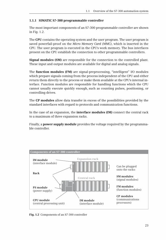
1 Introduction
24
112 Overview of STEP 7 Professional V12
STEP 7 is the central automation tool for SIMATIC STEP 7 requires authorization(licensing) and is executed on the current Microsoft Windows operating systemsConfiguration of an S7-300 controller is carried out in two views the Portal viewand the Project view
The Portal view is task-oriented
In the Start portal you can open an existing project create a new project or migratea project A ldquoprojectrdquo is a data structure containing all the programs and data re-quired for your automation task The most important STEP 7 tools and functionscan be accessed from here via further portals (Fig 13)
b In the Devices amp networks portal you configure the programmable controllersie you position the modules in a rack and set their parameters
b In the PLC programming portal you create the user program in the form of indi-vidual sections referred to as ldquoblocksrdquo
b The Visualization portal provides the most important tools for configuration andsimulation of HMI systems using SIMATIC WinCC
b In the Motion amp Technology portal you insert a technology object for PID Controland edit it
Fig 13 Tools in the Start portal of STEP 7 Professional V12
11 Overview of the S7-300 automation system
25
b The Online amp Diagnostics portal allows you to connect the programming deviceonline to a CPU You can control the CPUs operating modes and transfer and testthe user program
The Project view is an object-oriented view with several windows whose contentschange depending on the current activity In the Device configuration the focalpoint is the working area with the device to be configured The Device view in-cludes the rack and the modules which have already been positioned (Fig 14) Afurther window ndash the inspector window ndash displays the properties of the selectedmodule and the task card provides support by means of the hardware catalog withthe available modules The Network view allows networking between PLC and HMIstations
When carrying out PLC programming you edit the selected block in the workingarea You are again shown the properties of the selected object in the inspector win-dow where you can adjust them In this case the task card contains the programelements catalog with the available program elements and instructions The sameapplies to the processing of PLC tags or to online program testing using watch ta-bles
Fig 14 Example of a Project view working area of the device configuration
1 Introduction
26
And you always have a view of the project tree This contains all objects of the STEP 7project You can therefore select an object at any time for example a program blockor watch table and edit this object using the corresponding editors which start au-tomatically when the object is opened
113 Five programming languages
You can select between five programming languages for the user program ladderlogic (LAD) function block diagram (FBD) statement list (STL) structured controllanguage (SCL) and sequential control (GRAPH)
Using the ladder logic you program the control task based on the circuit diagramOperations on binary signal states are represented by serial or parallel arrange-ment of contacts and coils (Fig 15) Complex functions such as arithmetic func-tions are represented by boxes which you arrange like contacts or coils in the ladderlogic
Using the function block diagram you program the control task based on electroniccircuitry systems Binary operations are implemented by linking AND and OR func-tions and are terminated by memory boxes (Fig 16) Complex boxes are used to han-dle the operations on digital tags for example with arithmetic functions
Fig 15 Example of representation in ladder logic
Fig 16 Example of representation in function block diagram
11 Overview of the S7-300 automation system
27
Using the statement list you program the control task using a sequence of state-ments Every STL statement contains the specification of what has to be done andpossibly an operand with which the operation is executed STL is equally suitable forbinary and digital operations and for programming complex open-loop control tasks(Fig 17)
Fig 17 Example of STL statements
Fig 18 Example of SCL statements
Fig 19 Example of a GRAPH sequencer and step configuration
1 Introduction
28
Structured control language is particularly suitable for programming complex al-gorithms or for tasks in the area of data management The program is made up of SCLstatements which for example can be value assignments comparisons or controlstatements (Fig 18)
Using GRAPH you program a control task as a sequential control in which a se-quence of actions prevails The individual steps and branches are enabled by step en-abling conditions which can be programmed using LAD or FBD (Fig 19)
114 Execution of the user program
After the power supply has been switched on the control processor checks the con-sistency of the hardware and parameterizes the modules A startup program is thenexecuted once if present The startup program belongs to the user program whichyou produce Modules can be initialized for example by the startup program
The user program is usually divided into individual sections called ldquoblocksrdquo Orga-nization blocks (OB) represent the interface between operating system and userprogram The operating system calls an organization block for specific events andthe user program is then processed in it (Fig 110)
Function blocks (FB) and functions (FC) are available for structuring the programFunction blocks have a memory in which local tags are saved permanently func-tions do not have this memory
Fig 110 Execution of the user program
Startupprogram
Alarm and errorprogram
Mainprogram
Execution of the user program
Switching on
Updating of inputsand outputs
Interruption(alarm or error)
Operating modeSTARTUP
Operating system User program
Operating modeRUN
OB
OB
FBFC
FBFC
FBFC
FBFC
FBFC
FBFC
OB
Interruption
11 Overview of the S7-300 automation system
29
Program instructions are available for calling function blocks and functions (startof execution) Each block call can be assigned inputs and outputs referred to asldquoblock parametersrdquo During calling tags can be transferred with which the pro-gram in the block is to work In this manner a block can be repeatedly called with acertain function (eg addition of three tags) but with different parameters sets(eg for different calculations) (Fig 111)
The data of the user program is saved in data blocks (DB) Instance data blocks havea fixed assignment to a call of a function block and are the tag memory of the func-tion block Global data blocks contain data which is not assigned to any block
Following a startup the control processor updates the input and output signals inthe process images and calls the organization block OB 1 The main program ispresent here Structuring is also possible (and recommended) in the main pro-gram Once the main program has been processed the control processor returns tothe operating system retains (for example) communication with the programmingdevice updates the input and output signals and then recommences with execu-tion of the main program
Cyclic program execution is a feature of programmable logic controllers The userprogram is even executed if no actions are requested ldquofrom outsiderdquo eg if the con-trolled machine is not running This provides advantages when programmingFor example you program the ladder logic as if you were drawing a circuit diagramor program the function block diagram as if you were connecting electronic compo-nents Roughly speaking a programmable controller has a characteristic like forexample a contactor or relay control the many programmed operations are effec-tive quasi simultaneously ldquoin parallelrdquo
In addition to the cyclically executed main program it is possible to carry out inter-rupt-controlled program execution You must enable the corresponding interrupt
Fig 111 Example of two block calls with different tags in each case

11 Overview of the S7-300 automation system
25
b The Online amp Diagnostics portal allows you to connect the programming deviceonline to a CPU You can control the CPUs operating modes and transfer and testthe user program
The Project view is an object-oriented view with several windows whose contentschange depending on the current activity In the Device configuration the focalpoint is the working area with the device to be configured The Device view in-cludes the rack and the modules which have already been positioned (Fig 14) Afurther window ndash the inspector window ndash displays the properties of the selectedmodule and the task card provides support by means of the hardware catalog withthe available modules The Network view allows networking between PLC and HMIstations
When carrying out PLC programming you edit the selected block in the workingarea You are again shown the properties of the selected object in the inspector win-dow where you can adjust them In this case the task card contains the programelements catalog with the available program elements and instructions The sameapplies to the processing of PLC tags or to online program testing using watch ta-bles
Fig 14 Example of a Project view working area of the device configuration
1 Introduction
26
And you always have a view of the project tree This contains all objects of the STEP 7project You can therefore select an object at any time for example a program blockor watch table and edit this object using the corresponding editors which start au-tomatically when the object is opened
113 Five programming languages
You can select between five programming languages for the user program ladderlogic (LAD) function block diagram (FBD) statement list (STL) structured controllanguage (SCL) and sequential control (GRAPH)
Using the ladder logic you program the control task based on the circuit diagramOperations on binary signal states are represented by serial or parallel arrange-ment of contacts and coils (Fig 15) Complex functions such as arithmetic func-tions are represented by boxes which you arrange like contacts or coils in the ladderlogic
Using the function block diagram you program the control task based on electroniccircuitry systems Binary operations are implemented by linking AND and OR func-tions and are terminated by memory boxes (Fig 16) Complex boxes are used to han-dle the operations on digital tags for example with arithmetic functions
Fig 15 Example of representation in ladder logic
Fig 16 Example of representation in function block diagram
11 Overview of the S7-300 automation system
27
Using the statement list you program the control task using a sequence of state-ments Every STL statement contains the specification of what has to be done andpossibly an operand with which the operation is executed STL is equally suitable forbinary and digital operations and for programming complex open-loop control tasks(Fig 17)
Fig 17 Example of STL statements
Fig 18 Example of SCL statements
Fig 19 Example of a GRAPH sequencer and step configuration
1 Introduction
28
Structured control language is particularly suitable for programming complex al-gorithms or for tasks in the area of data management The program is made up of SCLstatements which for example can be value assignments comparisons or controlstatements (Fig 18)
Using GRAPH you program a control task as a sequential control in which a se-quence of actions prevails The individual steps and branches are enabled by step en-abling conditions which can be programmed using LAD or FBD (Fig 19)
114 Execution of the user program
After the power supply has been switched on the control processor checks the con-sistency of the hardware and parameterizes the modules A startup program is thenexecuted once if present The startup program belongs to the user program whichyou produce Modules can be initialized for example by the startup program
The user program is usually divided into individual sections called ldquoblocksrdquo Orga-nization blocks (OB) represent the interface between operating system and userprogram The operating system calls an organization block for specific events andthe user program is then processed in it (Fig 110)
Function blocks (FB) and functions (FC) are available for structuring the programFunction blocks have a memory in which local tags are saved permanently func-tions do not have this memory
Fig 110 Execution of the user program
Startupprogram
Alarm and errorprogram
Mainprogram
Execution of the user program
Switching on
Updating of inputsand outputs
Interruption(alarm or error)
Operating modeSTARTUP
Operating system User program
Operating modeRUN
OB
OB
FBFC
FBFC
FBFC
FBFC
FBFC
FBFC
OB
Interruption
11 Overview of the S7-300 automation system
29
Program instructions are available for calling function blocks and functions (startof execution) Each block call can be assigned inputs and outputs referred to asldquoblock parametersrdquo During calling tags can be transferred with which the pro-gram in the block is to work In this manner a block can be repeatedly called with acertain function (eg addition of three tags) but with different parameters sets(eg for different calculations) (Fig 111)
The data of the user program is saved in data blocks (DB) Instance data blocks havea fixed assignment to a call of a function block and are the tag memory of the func-tion block Global data blocks contain data which is not assigned to any block
Following a startup the control processor updates the input and output signals inthe process images and calls the organization block OB 1 The main program ispresent here Structuring is also possible (and recommended) in the main pro-gram Once the main program has been processed the control processor returns tothe operating system retains (for example) communication with the programmingdevice updates the input and output signals and then recommences with execu-tion of the main program
Cyclic program execution is a feature of programmable logic controllers The userprogram is even executed if no actions are requested ldquofrom outsiderdquo eg if the con-trolled machine is not running This provides advantages when programmingFor example you program the ladder logic as if you were drawing a circuit diagramor program the function block diagram as if you were connecting electronic compo-nents Roughly speaking a programmable controller has a characteristic like forexample a contactor or relay control the many programmed operations are effec-tive quasi simultaneously ldquoin parallelrdquo
In addition to the cyclically executed main program it is possible to carry out inter-rupt-controlled program execution You must enable the corresponding interrupt
Fig 111 Example of two block calls with different tags in each case

1 Introduction
26
And you always have a view of the project tree This contains all objects of the STEP 7project You can therefore select an object at any time for example a program blockor watch table and edit this object using the corresponding editors which start au-tomatically when the object is opened
113 Five programming languages
You can select between five programming languages for the user program ladderlogic (LAD) function block diagram (FBD) statement list (STL) structured controllanguage (SCL) and sequential control (GRAPH)
Using the ladder logic you program the control task based on the circuit diagramOperations on binary signal states are represented by serial or parallel arrange-ment of contacts and coils (Fig 15) Complex functions such as arithmetic func-tions are represented by boxes which you arrange like contacts or coils in the ladderlogic
Using the function block diagram you program the control task based on electroniccircuitry systems Binary operations are implemented by linking AND and OR func-tions and are terminated by memory boxes (Fig 16) Complex boxes are used to han-dle the operations on digital tags for example with arithmetic functions
Fig 15 Example of representation in ladder logic
Fig 16 Example of representation in function block diagram
11 Overview of the S7-300 automation system
27
Using the statement list you program the control task using a sequence of state-ments Every STL statement contains the specification of what has to be done andpossibly an operand with which the operation is executed STL is equally suitable forbinary and digital operations and for programming complex open-loop control tasks(Fig 17)
Fig 17 Example of STL statements
Fig 18 Example of SCL statements
Fig 19 Example of a GRAPH sequencer and step configuration
1 Introduction
28
Structured control language is particularly suitable for programming complex al-gorithms or for tasks in the area of data management The program is made up of SCLstatements which for example can be value assignments comparisons or controlstatements (Fig 18)
Using GRAPH you program a control task as a sequential control in which a se-quence of actions prevails The individual steps and branches are enabled by step en-abling conditions which can be programmed using LAD or FBD (Fig 19)
114 Execution of the user program
After the power supply has been switched on the control processor checks the con-sistency of the hardware and parameterizes the modules A startup program is thenexecuted once if present The startup program belongs to the user program whichyou produce Modules can be initialized for example by the startup program
The user program is usually divided into individual sections called ldquoblocksrdquo Orga-nization blocks (OB) represent the interface between operating system and userprogram The operating system calls an organization block for specific events andthe user program is then processed in it (Fig 110)
Function blocks (FB) and functions (FC) are available for structuring the programFunction blocks have a memory in which local tags are saved permanently func-tions do not have this memory
Fig 110 Execution of the user program
Startupprogram
Alarm and errorprogram
Mainprogram
Execution of the user program
Switching on
Updating of inputsand outputs
Interruption(alarm or error)
Operating modeSTARTUP
Operating system User program
Operating modeRUN
OB
OB
FBFC
FBFC
FBFC
FBFC
FBFC
FBFC
OB
Interruption
11 Overview of the S7-300 automation system
29
Program instructions are available for calling function blocks and functions (startof execution) Each block call can be assigned inputs and outputs referred to asldquoblock parametersrdquo During calling tags can be transferred with which the pro-gram in the block is to work In this manner a block can be repeatedly called with acertain function (eg addition of three tags) but with different parameters sets(eg for different calculations) (Fig 111)
The data of the user program is saved in data blocks (DB) Instance data blocks havea fixed assignment to a call of a function block and are the tag memory of the func-tion block Global data blocks contain data which is not assigned to any block
Following a startup the control processor updates the input and output signals inthe process images and calls the organization block OB 1 The main program ispresent here Structuring is also possible (and recommended) in the main pro-gram Once the main program has been processed the control processor returns tothe operating system retains (for example) communication with the programmingdevice updates the input and output signals and then recommences with execu-tion of the main program
Cyclic program execution is a feature of programmable logic controllers The userprogram is even executed if no actions are requested ldquofrom outsiderdquo eg if the con-trolled machine is not running This provides advantages when programmingFor example you program the ladder logic as if you were drawing a circuit diagramor program the function block diagram as if you were connecting electronic compo-nents Roughly speaking a programmable controller has a characteristic like forexample a contactor or relay control the many programmed operations are effec-tive quasi simultaneously ldquoin parallelrdquo
In addition to the cyclically executed main program it is possible to carry out inter-rupt-controlled program execution You must enable the corresponding interrupt
Fig 111 Example of two block calls with different tags in each case
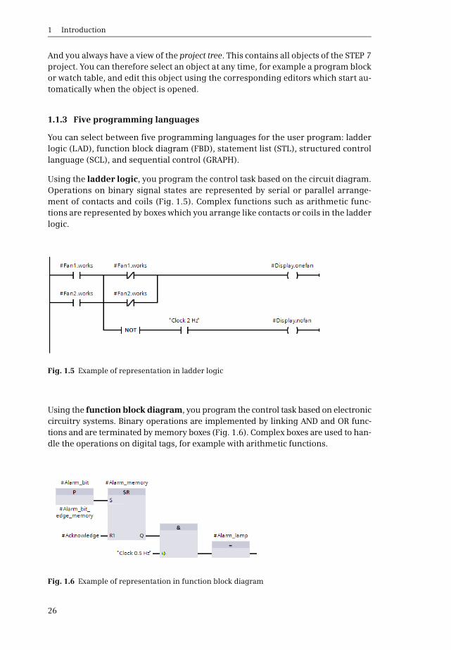
11 Overview of the S7-300 automation system
27
Using the statement list you program the control task using a sequence of state-ments Every STL statement contains the specification of what has to be done andpossibly an operand with which the operation is executed STL is equally suitable forbinary and digital operations and for programming complex open-loop control tasks(Fig 17)
Fig 17 Example of STL statements
Fig 18 Example of SCL statements
Fig 19 Example of a GRAPH sequencer and step configuration
1 Introduction
28
Structured control language is particularly suitable for programming complex al-gorithms or for tasks in the area of data management The program is made up of SCLstatements which for example can be value assignments comparisons or controlstatements (Fig 18)
Using GRAPH you program a control task as a sequential control in which a se-quence of actions prevails The individual steps and branches are enabled by step en-abling conditions which can be programmed using LAD or FBD (Fig 19)
114 Execution of the user program
After the power supply has been switched on the control processor checks the con-sistency of the hardware and parameterizes the modules A startup program is thenexecuted once if present The startup program belongs to the user program whichyou produce Modules can be initialized for example by the startup program
The user program is usually divided into individual sections called ldquoblocksrdquo Orga-nization blocks (OB) represent the interface between operating system and userprogram The operating system calls an organization block for specific events andthe user program is then processed in it (Fig 110)
Function blocks (FB) and functions (FC) are available for structuring the programFunction blocks have a memory in which local tags are saved permanently func-tions do not have this memory
Fig 110 Execution of the user program
Startupprogram
Alarm and errorprogram
Mainprogram
Execution of the user program
Switching on
Updating of inputsand outputs
Interruption(alarm or error)
Operating modeSTARTUP
Operating system User program
Operating modeRUN
OB
OB
FBFC
FBFC
FBFC
FBFC
FBFC
FBFC
OB
Interruption
11 Overview of the S7-300 automation system
29
Program instructions are available for calling function blocks and functions (startof execution) Each block call can be assigned inputs and outputs referred to asldquoblock parametersrdquo During calling tags can be transferred with which the pro-gram in the block is to work In this manner a block can be repeatedly called with acertain function (eg addition of three tags) but with different parameters sets(eg for different calculations) (Fig 111)
The data of the user program is saved in data blocks (DB) Instance data blocks havea fixed assignment to a call of a function block and are the tag memory of the func-tion block Global data blocks contain data which is not assigned to any block
Following a startup the control processor updates the input and output signals inthe process images and calls the organization block OB 1 The main program ispresent here Structuring is also possible (and recommended) in the main pro-gram Once the main program has been processed the control processor returns tothe operating system retains (for example) communication with the programmingdevice updates the input and output signals and then recommences with execu-tion of the main program
Cyclic program execution is a feature of programmable logic controllers The userprogram is even executed if no actions are requested ldquofrom outsiderdquo eg if the con-trolled machine is not running This provides advantages when programmingFor example you program the ladder logic as if you were drawing a circuit diagramor program the function block diagram as if you were connecting electronic compo-nents Roughly speaking a programmable controller has a characteristic like forexample a contactor or relay control the many programmed operations are effec-tive quasi simultaneously ldquoin parallelrdquo
In addition to the cyclically executed main program it is possible to carry out inter-rupt-controlled program execution You must enable the corresponding interrupt
Fig 111 Example of two block calls with different tags in each case
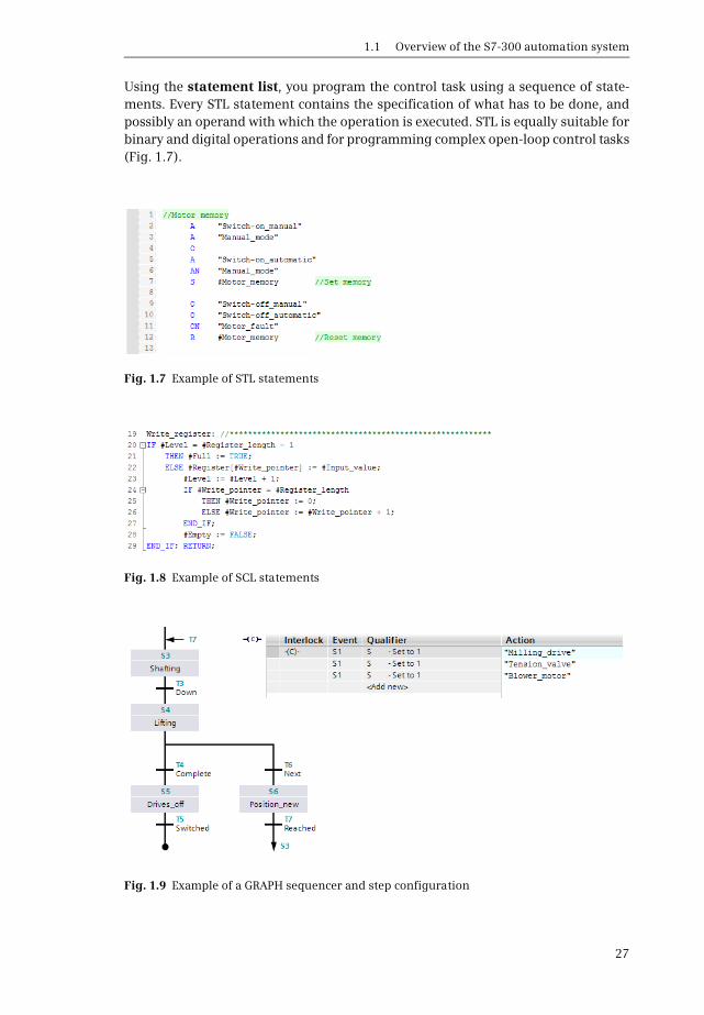