battery status monitor - schneider electric · relay chargers ... track energy consumption and...
TRANSCRIPT

Installation &Operator’s Guide
TM500ABattery Status Monitor
™
© 2001 Xantrex Technology Inc.P/N 973-0012-01-02 Rev. A 05/01
About XantrexXantrex Technology Inc., is a world-leading supplier of advanced power
electronics and controls with products from 50 watt portables to 1 megawattutility-scale systems for wind, solar, batteries, fuel cells, microturbines, andbackup power applications in both grid-connected and stand-alone systems.Xantrex products include inverters, battery chargers, programmable powersupplies, and variable speed drives that convert, supply, control, clean, anddistribute electrical power.
TrademarksTrace is a trademark of Xantrex Technology Inc. Xantrex is a registered
trademark of Xantrex Technology Inc.
Notice of CopyrightXantrex TM500A Battery Status Monitor © May 2001 Xantrex Technology.
All rights reserved.
DisclaimersWhile every precaution has been taken to ensure the accuracy of the
contents of this guide, Xantrex Technology Inc., assumes no responsibility forerrors or omissions. Note as well that specifications and product functional-ity may change without notice.
Since the use of this manual and the conditions or methods of installa-tion, operation, use and maintenance of the unit are beyond the control ofXantrex Technology Inc., the company does not assume responsibility andexpressly disclaims liability for loss, damage, or expense arising out of or anyway connected with such installation, operation, use, or maintenance.
Due to continual improvement through product updates, photographsand/or illustrations used in this manual may not exactly match your unit.Xantrex Technology Inc., reserves the right to update this product withoutnotice or releasing an updated manual when fit, form or function are notaffected.
Date and RevisionMay 2001, Revision A
Part Number973-0012-01-02
Contact InformationWeb: www.xantrex.comEmail: [email protected]: 360/435.8826Fax: 360/474.0616

© 2001 Xantrex Technology Inc.P/N 973-0012-01-02 Rev. A 05/01
i
Table of Contents
1.0 INTRODUCTION ...............................................................1The TM500A .......................................................................................... 1Unpacking and Inspection ..................................................................... 2TM500A (12/24 Volt) ............................................................................. 2TM500A - NS (12/24 Volt) ..................................................................... 2TM48 (48 Volt) ....................................................................................... 2
2.0 INSTALLATION ................................................................3Required Tools ....................................................................................... 3Pre-Installation ....................................................................................... 3Mounting ................................................................................................ 3
Surface Mounting .............................................................................. 4Flush Mounting .................................................................................. 6Extended Length Installations ........................................................... 8
Deltec™ Shunt ...................................................................................... 9Mounting/Wiring the Shunt ................................................................ 9Mounting Circuit Board to an Existing Shunt .................................. 10Connecting the Shunt Board ........................................................... 11
3.0 CONFIGURATION........................................................... 12Setup ................................................................................................... 12Restoring the Factory Defaults ........................................................... 12Setting Parameters .............................................................................. 13Charge Efficiency % .......................................................................... 14
Setting the Charge Efficiency Factor ............................................. 14
Amp Hours Ah .................................................................................... 15Setting the Amp Hours .................................................................... 15
CHARGED Indicator Setup ............................................................ 17 Trigger on Voltage Only ..................................................................... 17
Trigger on Voltage and Amperage .................................................. 19Trigger on Voltage and Time ........................................................... 21Charger Considerations .................................................................. 23
Relay Chargers ........................................................................... 23Taper Chargers ........................................................................... 23Three-stage Chargers ................................................................ 23
Low-Voltage Indicator V ................................................................... 24Configuring the Low-Voltage Alarm ............................................... 24

© 2001 Xantrex Technology Inc.P/N 973-0012-01-02 Rev. A 05/01
ii
Table of Contents(continued)
4.0 OPERATION ................................................................... 25Indicators and Controls ....................................................................... 25Buttons ................................................................................................ 25
Select Button ................................................................................... 25Reset Button .................................................................................... 25INVERTER ON/OFF Button .............................................................. 25
Basic Meters ....................................................................................... 26Available Meters ............................................................................. 26
% (state-of charge) .................................................................... 26V (Volts) ...................................................................................... 26A (AMPS) ..................................................................................... 26Ah (AMP HOURS) ....................................................................... 27
Power Saving Mode ........................................................................ 27Data Monitors ...................................................................................... 28Reminders and Indicators ................................................................... 30
Amp-hour Reminder ........................................................................ 30Low-Voltage Indicator ..................................................................... 31CHARGED Indicator ......................................................................... 32
5.0 TROUBLESHOOTING .................................................... 33
6.0 SERVICE INFORMATION ............................................... 34
7.0 SPECIFICATIONS .......................................................... 35
8.0 WARRANTY .................................................................... 36

© 2001 Xantrex Technology Inc.P/N 973-0012-01-02 Rev. A 05/01
IMPORTANT SAFETY INSTRUCTIONS
This manual contains important safety instructions that should be followedduring the installation and maintenance of this product.
To reduce the risk of electrical shock, and to ensure the safe installation andoperation of this product, the following safety symbols have been placedthroughout this manual to indicate dangerous conditions and important safetyinstructions.
WARNING - A dangerous voltage or condition exists in this area.Use extreme caution when performing these tasks.
AVERTISSEMENT - Une tension ou condition dangereuse existe danscette zone. Faire preuve d’extrême prudence lors de la réalisation deces tâches.
CAUTION - This procedure is critical to the safe installation oroperation of the unit. Follow these instructions closely.
ATTENTION - Cette procédure est essentielle à l’installation oul’utilisation de l’unité en toute sécurité. Suivre ces instructions deprès.
NOTE - This statement is important. Follow instructions closely.
NOTE - Cette déclaration est importante. Suivre les instructions deprès.
• All electrical work must be done in accordance with local, national,and/or international electrical codes.
• Before installing or using this device, read all instructions and cautionarymarkings located in (or on) the TM500A, the manual, the batteries, theinverter, the PV array, etc.
• Do not expose this unit to rain, snow or liquids of any type. This product isdesigned only for indoor mounting.
• To reduce the chance of short-circuits when installing or working with theinverter, the batteries, or the PV array, use insulated tools.
• Remove all jewelry such as rings, bracelets, necklaces, etc., whileinstalling this system. This will greatly reduce the chance of accidentalexposure to live circuits.
• The inverter contains more than one live circuit (batteries, PV array, andAC). Power may be present at more than one source.
• This product contains no user-serviceable parts. Do not attempt to repairthis unit.
iii

© 2001 Xantrex Technology Inc.P/N 973-0012-01-02 Rev. A 05/01
BATTERY SAFETY INFORMATION• Always wear eye protection, such as safety glasses, when working with
batteries.
• Remove all loose jewelry before working with batteries.
• Never work alone. Have someone assist you with the installation or beclose enough to come to your aid when working with batteries.
• NEVER smoke in the vicinity of a battery or generator.
• Always connect the batteries first, then connect the cables to the invertervia a DC disconnect switched OFF. This will greatly reduce the chance ofspark in the vicinity of the batteries.
• Use insulated tools when working with batteries.
• When connecting batteries, always verify proper voltage and polarity.
• Do not short-circuit battery cables. Fire or explosion can occur.
• In the event of exposure to battery electrolyte, wash the area with soapand water. If acid enters the eyes, flood them with running cold water forat least 15 minutes and get immediate medical attention.
SAVE THESE INSTRUCTIONSiv

1© 2001 Xantrex Technology Inc.P/N 973-0012-01-02 Rev. A 05/01
The TM500AThe TM500A features six data monitoring functions and three indicators
including:
• State of charge/amp-hour content (full or percent of capacity)
• State of charge/voltage (real-time voltage level, historical high and lowsystem voltage)
• Amps (real-time amps, total charging amps, total load amps)
• Amp hours removed
• Days since fully charged
• Cumulative amp hours
• Recharge indicator
• Low-voltage indicator
• Full-charge indicator
The unit is configurable for specific system or application functions suchas setting the CHARGED indication parameters, battery capacity, chargingefficiency, low-battery warning conditions and a recharge reminder. TheTM500A can monitor any battery supply from approximately 8 to 65 volts,track energy consumption and estimate remaining battery life.
In addition to its status monitoring features, the unit can act as a remotecontrol, switching the inverter OFF or ON (only on inverters incorporating anRC4/RC8 compatible remote control jack).
The TM500A operates on 12-, 24-, or 48-volt battery systems (48-voltsystems require an optional shunt board).
Figure 1-1The TM500A
14.2
1.0 INTRODUCTION
2 © 2001 Xantrex Technology Inc.P/N 973-0012-01-02 Rev. A 05/01
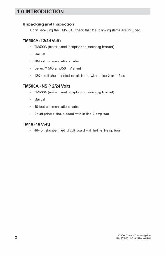
Unpacking and InspectionUpon receiving the TM500A, check that the following items are included.
TM500A (12/24 Volt)• TM500A (meter panel, adaptor and mounting bracket)
• Manual
• 50-foot communications cable
• Deltec™ 500 amp/50 mV shunt
• 12/24 volt shunt-printed circuit board with in-line 2-amp fuse
TM500A - NS (12/24 Volt)• TM500A (meter panel, adaptor and mounting bracket)
• Manual
• 50-foot communications cable
• Shunt-printed circuit board with in-line 2-amp fuse
TM48 (48 Volt)• 48-volt shunt-printed circuit board with in-line 2-amp fuse
1.0 INTRODUCTION

3© 2001 Xantrex Technology Inc.P/N 973-0012-01-02 Rev. A 05/01
Required Tools• Phillips screw driver• 3/32" and 3/16" drill bits• Hole saw
If the TM500A will also function as a remote control (INVERTER ON/OFF),an additional cable must be ordered. Available lengths are:
10 feet–TC/10 25 feet–TC/2550 feet–TC/50 100 feet–TC/100
Pre-InstallationBefore installing the TM500A, read all instructions and cautionary
markings located in this manual. The unit should be mounted in a clean, dry,protected environment.
Determine the wire route to the batteries (and inverter, if the remoteINVERTER ON/OFF function is desired).
NOTE: Check for existing electrical, plumbing or other potentialareas of accidental damage prior to making cuts in structuralsurfaces.
MountingThe unit can be surface mounted (using the adaptor supplied) or flush
mounted into a rectangular opening. Provide at least one inch clearancebehind the meter circuit board for the cabling when flush mounting.
The TM500A ships in three sections:
• TM500A• Adaptor for surface mounting• Mounting Bracket
Figure 2-1TM500A and Mounting Components
Trace MeterPanel
Adaptor Mounting
2.0 INSTALLATION

4 © 2001 Xantrex Technology Inc.P/N 973-0012-01-02 Rev. A 05/01
Surface Mounting• Using the mounting bracket as a template, mark the positions for the
screw holes and an area where the cable(s) will feed through.
• Drill out the four screws holes (if required) and wire access opening.Use a 3/16" bit if the supplied plastic anchors are used. If placing thescrews directly into the backing material, use a 3/32" bit. The wireaccess hole should be at least 1/2" diameter to allow the connector topass through.
• Mount the bracket using the screws (and anchors if necessary)supplied. See Figure 2-2. Do not overtighten the screws.
• Install the adaptor onto the bracket by pressing it tightly into place.
• Connect the communications cable (from the shunt) to the “J1 TOSHUNT ONLY” jack on the TM500A. See Figure 2-3.
• If the TM500A is to function as an ON/OFF remote control for theinverter, connect the remote control cable (not supplied) to the “J2INVERTER ONLY” jack. This connector only functions if the invertercontains a REMOTE jack that allows operation with an RC4 or RC8remote control.
CAUTION: Do not reverse these cables or the TM500Acircuit board will be permanently damaged.
• Install the meter onto the adaptor by pressing it tightly into place.
2.0 INSTALLATION

5© 2001 Xantrex Technology Inc.P/N 973-0012-01-02 Rev. A 05/01
Figure 2-2Surface Mounting the TM500A Using the Adaptor
WireAccess
Hole
Trace MeterBracket
Trace MeterAdaptor
Trace Meter
Figure 2-3Communication and Remote Cable Connections
J2 TOINVERTER
ONLYJ1 TO
SHUNTONLY
SPADE LUG
2.0 INSTALLATION

6 © 2001 Xantrex Technology Inc.P/N 973-0012-01-02 Rev. A 05/01
Flush MountingTo flush mount the TM500A , an opening must be cut in the backing
material to allow room for the circuit board, wires and connectors. Allow atleast one inch depth behind the circuit board for the connectors and wires.
• Use the bracket as a template and mark the positions for the screwholes. Mark the open area to be cut out for the circuit board.
NOTE: Carefully cut out the circuit board area from the backingmaterial (i.e., wallboard). Cut inside the lines so there is enougharea left to securely hold the screws.
• Drill out the four screw’s holes (if required) and wire access opening.Use a 3/16" bit if the supplied plastic anchors are used. If placing thescrews directly into the backing material, use a 3/32" bit.
• Mount the bracket using the screws (and anchors if necessary)supplied. See Figure 2-4. Do not overtighten the screws.
• Connect the communications cable (from the shunt) to the “J1 TOSHUNT ONLY” jack (Figure 2-5).
• If the TM500A is to function as an ON/OFF remote control for theinverter, connect the remote control cable (not supplied) to the “J2INVERTER ONLY” jack. This connector only functions if the invertercontains a REMOTE jack that allows operation with an RC4 or RC8remote control.
CAUTION: Do not reverse these cables or the TM500A circuitboard will be permanently damaged. This is not coveredunder warranty.
• Install the meter onto the bracket by pressing it tightly into place.
2.0 INSTALLATION

7© 2001 Xantrex Technology Inc.P/N 973-0012-01-02 Rev. A 05/01
Figure 2-4Flush Mounting the TM500A
Area To Be Cut-Out
Trace MeterBracket
Trace Meter
Figure 2-5Communication and Remote Cable Connections
J2 TOINVERTER
ONLYJ1 TO
SHUNTONLY
SPADE LUG
2.0 INSTALLATION

8 © 2001 Xantrex Technology Inc.P/N 973-0012-01-02 Rev. A 05/01
Extended Length InstallationsIf the TM500A is mounted in excess of 100 feet from the inverter, an
additional wire (with a spade lugs on both ends) must be connected betweenthe TM500A and shunt spade lugs. This wire acts as a ground reference andensures the meter will read accurately.
Use the following gauge wire for the distance the TM500A is mountedfrom the inverter.
Maximum Distance Wire Gauge
250 feet #16 AWG400 feet #14 AWG630 feet #12 AWG
1000 feet #10 AWG
J2 TOINVERTER
ONLYJ1 TO
SHUNTONLY
SPADE LUG
SPADE LUG
Interconnect for distances over100 feet
Figure 2-6Extended Length Ground Wire
2.0 INSTALLATION

9© 2001 Xantrex Technology Inc.P/N 973-0012-01-02 Rev. A 05/01
Deltec™ Shunt
WARNING: BEFORE WIRING THE SHUNT TO THE BATTERIES,SWITCH THE DC DISCONNECT TO OFF AND/OR REMOVETHE DC FUSE.
Mounting/Wiring the ShuntThe shunt connects between the inverter and batteries in the
negative (–) line (Figure 2-10).
• Mount the shunt on or near the battery enclosure close to the negative(–) battery terminal. Use appropriate screws to secure the shunt to thebattery enclosure.
• Disconnect the NEGATIVE cable (that connects between the inverterand battery) from the battery’s negative (–) terminal.
• Connect the free end of the negative cable to the shunt’s terminallabeled “INVERTER.” Ensure all connections are tight.
• Connect a short length of cable (same gauge) between the battery’snegative(–) terminal and the shunt’s terminal labeled “BAT MINUS.”Ensure all connections are tight.
• Connect the cables and hardware to the shunt as shown in Figure 2-7.
NOTE: The cable connection must be flat against the shunt blockwith nothing between it for a good connection.
Figure 2-7Shunt Connections
To Inverter’sNegative Terminal
To Battery’sNegative Terminal
Shunt Hex Bolt (9/16 inch head)Split Lock WasherLarge WasherCable LugShunt
2.0 INSTALLATION

10 © 2001 Xantrex Technology Inc.P/N 973-0012-01-02 Rev. A 05/01
Mounting Circuit Board to an Existing ShuntModel TM500A - NS is supplied without a shunt and is intended to be
wired to an existing shunt. The kit includes two brass 8-32 x 5/8 inchmachine screws, two lock-washers and two metal standoffs.
NOTE: The shunt must be of the proper type (50 mV/500 amps) andhave the necessary threaded screw holes to accommodate the shuntboard.
• Remove the existing two machine screws (if installed) and hardwarefrom the side of the shunt.
• Install the shunt circuit board and supplied hardware exactly as shownin Figure 2-8.
NOTE: Use only the hardware supplied in the kit.
Figure 2-8Shunt Circuit Board and Hardware
Brass Screw
Metal Standoff
Brass LockWasher
Spade Lug(for extended length installations)
2.0 INSTALLATION

11© 2001 Xantrex Technology Inc.P/N 973-0012-01-02 Rev. A 05/01
Connecting the Shunt Board• Remove the fuse from the in-line fuse holder by rotating the fuse holder
cap counterclockwise.
• Connect the ring terminal from the fuse holder to the battery’s positiveterminal.
• Connect the shunt communications cable into the RJ11 jack on the shuntboard. This cable can be extended up to 100 feet (30 meters).
• Replace the fuse in the fuse holder. Replace the fuse holder cap bypushing and rotating it clockwise.
INVERTER
-
SHUNT
DC FUSEDISCONNECT
SHUNT IN-LINE FUSE
SHUNT WIRE
3507-00B-F01
J2J1
INVERTERRC4/RC8REMOTE
JACK
GROUND WIRE(IF RUN IS OVER
100 FEET)
SHUNT JACKREMOTE JACK
INVERTER ON/OFFREMOTE CABLE
TC10, TC25, TC50, TC100(NOT SUPPLIED)TRACE
METER(Back View)
BATTERY
+ -+
Figure 2-10Circuit Diagram
Figure 2-9In-line Fuse
In-line Fuse
To battery’spositiveterminal
To J1connector on
back ofmeter
2.0 INSTALLATION

12 © 2001 Xantrex Technology Inc.P/N 973-0012-01-02 Rev. A 05/01
SetupThe TM500A is configured at the factory for monitoring a 12 VDC
system. These settings can be changed to meet specific system parameters.
The default settings are:
% Charge Efficiency 94 %
V Voltage (full-charge) 14.4 volts DC
A Amperage DC 35 amps
Ah Amp Hours 200 HoursLow-Voltage Indicator 11.2 volts DCRecharge Reminder OFF
Restoring the Factory DefaultsThe factory defaults can be restored to their original settings if desired.
The default values will return to those listed above and are for a 12 VDCsystem.
To restore the factory defaults:
1. Set the TM500A into the power saving mode by repeatedly pressing theSELECT button until the LED display goes blank.
2. Press and hold the RESET button. The display will indicate “ALL”flashing in the display. Continue to hold the RESET button until the LEDdisplay remains blank.
The factory defaults are now restored.
Figure 3-1Resetting to Factory Defaults
A L L
Step 2 = ALL then blank
12
3.0 CONFIGURATION

© 2001 Xantrex Technology Inc. 13P/N 973-0012-01-02 Rev. A 05/01
Setting ParametersIndividual system parameters can be set by the following procedure:
1. Press the SELECT button until the mode selection indicator to be set isilluminated.
2. Press the SELECT and RESET buttons simulataniously. Release bothbuttons when the LED display flashes.
3. Press and release the RESET button to scroll through the selections (orvalues) slowly, or hold the RESET button to scroll rapidly.
4. When the desired value is shown in the LED display, press the SELECTbutton to accept it.
Figure 3-2Setting Parameters
1
Mode Indicators
Select Value
2
4
14.4
3
3.0 CONFIGURATION
14 © 2001 Xantrex Technology Inc.P/N 973-0012-01-02 Rev. A 05/01
Setting Parameters (continued)
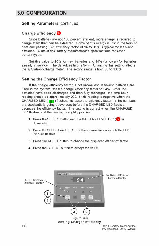
Charge Efficiency %
Since batteries are not 100 percent efficient, more energy is required tocharge them than can be extracted. Some of this energy is lost in the form ofheat and gassing. An efficiency factor of 94 to 98% is typical for lead-acidbatteries. Consult the battery manufacturer’s specifications for otherbattery types.
Set this value to 96% for new batteries and 94% (or lower) for batteriesalready in service. The default setting is 94%. Changing this setting affectsthe % State-of-Charge meter. The setting range is from 60 to 100%.
Setting the Charge Efficiency FactorIf the charge efficiency factor is not known and lead-acid batteries are
used in the system, set the charge efficiency factor to 94%. After thebatteries have been discharged and then fully recharged, the amp-hourreading should be approximately 000. If this reading is negative when theCHARGED LED ( ) flashes, increase the efficiency factor. If the numbersare substantially going above zero before the CHARGED LED flashes,decrease the efficiency factor. The setting is correct when the CHARGEDLED flashes and the reading is slightly positive.
1. Press the SELECT button until the BATTERY LEVEL LED ( % ) isilluminated.
2. Press the SELECT and RESET buttons simulataniously until the LEDdisplay flashes.
3. Press the RESET button to change the displayed efficiency factor.
4. Press the SELECT button to accept the value.
Figure 3-3Setting Charger Efficiency
Set Battery EfficiencyFactor in Display
% LED IndicatesEfficiency Function
4
1
2 3
9 4
3.0 CONFIGURATION

© 2001 Xantrex Technology Inc. 15P/N 973-0012-01-02 Rev. A 05/01
Setting Parameters (continued)
Amp Hours Ah
The amp-hour setting should be set to a value equal or lower than theactual amp-hour capacity of the system’s battery bank. Using a number thatis lower than the actual amp-hour capacity allows the % Battery State-of-Charge meter to provide a more conservative indication for the use of thebatteries to avoid excessively discharging them.
Also note the temperature at which the battery capacity is rated. Theamp-hour capacity of the batteries decreases at temperatures lower than therated value.
The amp-hour rating is usually printed on the battery’s label. If thesystem contains batteries in parallel, then the amp-hour rating of the parallelbatteries is added together (i.e., two 120 amp-hour rated batteries in parallelequals 240 amp hours). The amp-hour capacity of a bank does not increasefor series-wired batteries and is equal to the lowest rated battery in theseries string. If the amp-hour capacity is not listed on the battery, consult thebattery manufacturer or dealer for assistance.
Setting the Amp Hours1. Press the SELECT button until the AMP-HOURS LED ( Ah ) is illuminated.
2. Press the SELECT and RESET buttons simulataniously until the LEDdisplay flashes.
3. Press the RESET button to change the displayed amp hours to a valueslightly lower than the system’s total battery amp-hour capacity.
4. Press the SELECT button to accept the new value. The selection rangeis between 10 (010.) to 2,550 (2.55) Ah.
NOTE: When the flashing display indicates between 010. to 990.(decimal point after the right most digit), read the display directly.When the flashing display indicates between 1.00 to 2.55 (decimalpoint two places to the left), multiply the reading by 1000 (i.e., aflashing 160. equals 160 amp hours; a flashing 1.60 in the displayequals 1,600 amp hours).
3.0 CONFIGURATION

16 © 2001 Xantrex Technology Inc.P/N 973-0012-01-02 Rev. A 05/01
Figure 3-4Setting the Amp Hours
Setting Parameters (continued)
4
280.
Set Battery Amp-HourRating
2 31
Ah LED IndicatesAmp-Hour Function is
Selected
3.0 CONFIGURATION

© 2001 Xantrex Technology Inc. 17P/N 973-0012-01-02 Rev. A 05/01
Setting Parameters (continued)
CHARGED Indicator Setup The CHARGED indicator LED can be programmed to light when the
batteries are fully charged based on several different parameters:
• Trigger the LED when voltage only parameters are met• Trigger the LED when voltage and current parameters are met• Trigger the LED when voltage and time parameters are met
Trigger on Voltage OnlyWhen the TM500A is setup to trigger on voltage only, the CHARGED LED
illuminates when the voltage reaches the level programmed into the TM500A.
NOTE: This mode must be setup first before setting the Voltage andCurrent or Voltage and Time modes.
Step A Setting the Fully-Charged Voltage Level
1A. Press the SELECT button until the Voltage LED ( V ) is illuminated.
2A. Press the SELECT and RESET buttons simulataniously until the LEDdisplay flashes.
3A. Press the RESET button to change the displayed voltage to thedesired fully-charged voltage level:
• For a 12 VDC system, set this voltage between 14.3–14.9 volts forlead-acid batteries.
• For a 24 VDC system, set this voltage between 28.6–29.6 volts forlead-acid batteries.
• For a 48 VDC system, set this voltage between 57.2–59.2 volts forlead-acid batteries.
Refer to the battery manufacturer’s recommendation for other typesof batteries.
4A. Press the SELECT button to accept the new value. The selectionrange is between 10 to 64.9 VDC.
5A. Proceed to Step B.
NOTE: In 32–48 VDC systems, whenever a voltage above 35.0 voltsis selected, the display multiplies the actual voltage by 2 for theTM48 (48 V shunt adapter).
3.0 CONFIGURATION

18 © 2001 Xantrex Technology Inc.P/N 973-0012-01-02 Rev. A 05/01
Setting Parameters (continued)
CHARGED Indicator Setup (continued)
The fully-charged voltage parameters are now set. To allow the voltageonly setting to trigger the fully-charged LED, the amperage setting must beswitched OFF.
Step B Switching OFF the Amperage Detection
1B. Press the SELECT button until the Amperage LED ( A ) is illuminated.
2B. Press the SELECT and RESET buttons simulataniously until the LEDdisplay flashes.
3B. Press the RESET button until the display indicates OFF.4B. Press SELECT button to accept.
The TM500A is now setup to trigger the CHARGED indicator LED ( )when the voltage level equals or exceeds the value programmed in Step A.When this voltage parameter is met, the CHARGED indicator LED flashesapproximately every four seconds.
NOTE: The CHARGED indicator remains ON (solid) even when thebatteries are discharging, until reset.
Figure 3-5Setting the CHARGED Indicator Voltage Level
Figure 3-6Turn Amps OFF for VOLTAGE ONLY Detection
14.4Set Voltage Level
2A
Voltage LEDIlluminates to Indicatethe Voltage Function
is Selected
3A1A
4A
OFF
Set Amps toOFF
1B
4B
2B
Amperage LEDIlluminates to Indicate
the AmperageFunction is Selected
3B
3.0 CONFIGURATION

© 2001 Xantrex Technology Inc. 19P/N 973-0012-01-02 Rev. A 05/01
Setting Parameters (continued)
CHARGED Indicator Setup (continued)
Trigger on Voltage and AmperageWhen this mode is selected, the CHARGED indicator LED illuminates
when the voltage reaches the programmed level (Step A) and the amperagedecreases to the value set in Step B.
As batteries charge, their voltage slowly increases and the chargingcurrent decreases. Setting these parameters allows the CHARGED indicatorLED to illuminate when specified conditions are met. However, if a suffi-ciently high amperage is being drawn from DC loads during charging, themeter detects this current, and it prevents the TM500A from illuminating theCHARGED indicator LED. To set the meter to illuminate the CHARGED LED, theamperage trigger level must be increased to account for the additionalDC loads.
NOTE: The batteries may not be fully charged if DC loads are in thesystem and the current level is increased.
To determine the appropriate fully charged amperage for the system,divide the battery bank amp-hour capacity by 20. For example; if the batterybank’s amp-hour rating equals 880 amp hours, divide this value by 20 for anamperage setting of 44 amps.
Step A Setting the Fully-Charged Voltage Level
1A. Press the SELECT button until the Voltage LED ( V ) is illuminated.
2A. Press the SELECT and RESET buttons simulataniously until the LEDdisplay flashes.
3A. Press the RESET button to change the displayed voltage to thedesired fully charged voltage level:
• For a 12 VDC system, set this voltage between 14.3–14.9 volts forlead-acid batteries.
• For a 24 VDC system, set this voltage between 28.6–29.6 volts forlead-acid batteries.
• For a 48 VDC system, set this voltage between 57.2–59.2 volts forlead-acid batteries.
Refer to the battery manufacturer’s recommendation for other typesof batteries.
4A. Press the SELECT button to accept the new value. The selectionrange is between 10 to 64.9 VDC.
3.0 CONFIGURATION
20 © 2001 Xantrex Technology Inc.P/N 973-0012-01-02 Rev. A 05/01
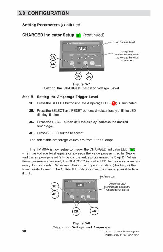
Step B Setting the Amperage Trigger Level
1B. Press the SELECT button until the Amperage LED ( A ) is illuminated.
2B. Press the SELECT and RESET buttons simulataniously until the LEDdisplay flashes.
3B. Press the RESET button until the display indicates the desiredamperage.
4B. Press SELECT button to accept.
The selectable amperage values are from 1 to 99 amps.
The TM500A is now setup to trigger the CHARGED indicator LED ( )when the voltage level equals or exceeds the value programmed in Step Aand the amperage level falls below the value programmed in Step B. Whenthese parameters are met, the CHARGED indicator LED flashes approximatelyevery four seconds. Whenever the current goes negative (discharge) thetimer resets to zero. The CHARGED indicator must be manually reset to turnit OFF.
Setting Parameters (continued)
CHARGED Indicator Setup (continued)
Figure 3-7Setting the CHARGED Indicator Voltage Level
Figure 3-8Trigger on Voltage and Amperage
14.4
Set Voltage Level
1A
4A
2A
Voltage LEDIlluminates to Indicatethe Voltage Function
is Selected
3A
44A
Set Amperage
Amperage LEDIlluminates to Indicate the
Amperage Function is
2B 3B
4B
1B
3.0 CONFIGURATION

© 2001 Xantrex Technology Inc. 21P/N 973-0012-01-02 Rev. A 05/01
Setting Parameters (continued)
CHARGED Indicator Setup (continued)
Trigger on Voltage and TimeWhen this mode is selected, the CHARGED indicator LED illuminates
when the voltage reaches the programmed level (Step A) and the amperageremains positive for the specified time (Step B).
Step A Setting the Fully-Charged Voltage Level
1A. Press the SELECT button until the Voltage LED ( V ) is illuminated.
2A. Press the SELECT and RESET buttons simulataniously until the LEDdisplay flashes.
3A. Press the RESET button to change the displayed voltage to thedesired fully charged voltage level.
• For a 12 VDC system, set this voltage between 14.3–14.9 volts forlead-acid batteries.
• For a 24 VDC system, set this voltage between 28.6–29.6 volts forlead-acid batteries.
• For a 48 VDC system, set this voltage between 57.2–59.2 volts forlead-acid batteries.
Refer to the battery manufacturer’s recommendation for other typesof batteries.
4A. Press the SELECT button to accept the new value.The selection range is between 10 to 64.9 VDC.
5A. Proceed to Step B.
14.4
Set Voltage Level
1A
4A
2A
Voltage LED Illuminatesto Indicate the VoltageFunction is Selected
3A
Figure 3-9Setting the CHARGED Indicator Voltage Level
3.0 CONFIGURATION

22 © 2001 Xantrex Technology Inc.P/N 973-0012-01-02 Rev. A 05/01
Setting Parameters (continued)
CHARGED Indicator Setup (continued)
Step B Setting the Time Duration
1B. Press the SELECT button until the Amperage LED ( A ) is illuminated.
2B. Press the SELECT and RESET buttons simulataniously until the LEDdisplay flashes.
3B. Press the RESET button until the display reaches the hour settings.These selections are available following the amperage settings.Select the desired time (in hours or tenths of hours); the voltage mustremain at this level to trigger the CHARGED LED.
4B. Press SELECT button to accept. The selectable amperage values arefrom 0.2H to 2.0H (12 minutes to 2 hours).
The TM500A is now setup to trigger the CHARGED indicator LED ( )when the voltage level equals or exceeds the value programmed in Step Aand the current remains positive for the time duration programmed in Step B.When these parameters are met, the CHARGED indicator LED flashesapproximately every four seconds. Whenever the current goes negative(discharging), the timer will reset to zero. The CHARGED indicator LED mustbe manually reset to turn it OFF.
Figure 3-10Trigger on Voltage and Time
1. H
Set Time Duration
1B
4B
3B2B
Amperage LEDIlluminates toIndicate theAmperageFunction isSelected
3.0 CONFIGURATION

© 2001 Xantrex Technology Inc. 23P/N 973-0012-01-02 Rev. A 05/01
Setting Parameters (continued)
CHARGED Indicator Setup (continued)
Charger ConsiderationsThere are several different types of chargers (relay, taper or three-
stage) which can affect the settings and prevent the CHARGE LED fromilluminating.
Relay ChargersRelay type chargers raise the battery to a set voltage level then shut
OFF using only voltage as their parameter. Set the TM500A to the voltageonly mode and set the voltage slightly below the charger turnoff setting.
Taper ChargersTaper type chargers raise the battery to a specified voltage and shut
OFF when the amperage decreases to a specified level. When usingtaper type chargers (pulse-width-modulated), set the voltage and taperamperage parameters slightly below that of the charger.
If the taper charger is a type that charges up to a certain level and thenwaits for a period of time to determine if the batteries are charged, thenset the TM500A to a voltage slightly below the charger’s settings. Set thetime a little shorter than the charger’s time period.
Three-stage ChargersThree-stage chargers raise the battery to a specified voltage level and
then maintain the batteries at a “Float” voltage and trickle current. Adjustthe TM500A’s voltage parameters slightly below the charger’s float voltagesetting. Set the amperage slightly below the charger’s float amperagesetting.
3.0 CONFIGURATION
24 © 2001 Xantrex Technology Inc.P/N 973-0012-01-02 Rev. A 05/01
Setting Parameters (continued)
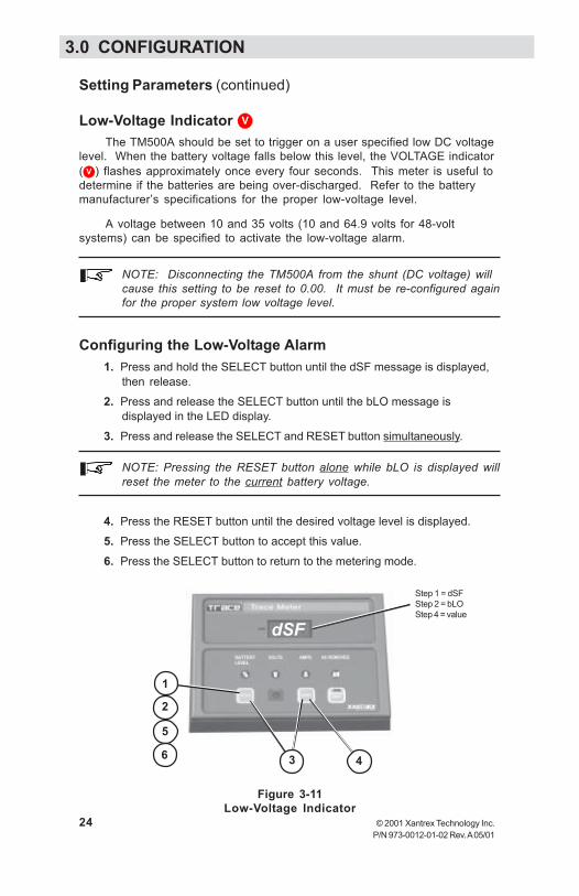
Low-Voltage Indicator V
The TM500A should be set to trigger on a user specified low DC voltagelevel. When the battery voltage falls below this level, the VOLTAGE indicator( V ) flashes approximately once every four seconds. This meter is useful todetermine if the batteries are being over-discharged. Refer to the batterymanufacturer’s specifications for the proper low-voltage level.
A voltage between 10 and 35 volts (10 and 64.9 volts for 48-voltsystems) can be specified to activate the low-voltage alarm.
NOTE: Disconnecting the TM500A from the shunt (DC voltage) willcause this setting to be reset to 0.00. It must be re-configured againfor the proper system low voltage level.
Configuring the Low-Voltage Alarm1. Press and hold the SELECT button until the dSF message is displayed,
then release.2. Press and release the SELECT button until the bLO message is
displayed in the LED display.
3. Press and release the SELECT and RESET button simultaneously.
NOTE: Pressing the RESET button alone while bLO is displayed willreset the meter to the current battery voltage.
4. Press the RESET button until the desired voltage level is displayed.5. Press the SELECT button to accept this value.
6. Press the SELECT button to return to the metering mode.
Figure 3-11Low-Voltage Indicator
dSF
4
1
5
2
3
Step 1 = dSFStep 2 = bLOStep 4 = value
6
3.0 CONFIGURATION

© 2001 Xantrex Technology Inc. 25P/N 973-0012-01-02 Rev. A 05/01
Indicators and ControlsThe TM500A contains the following controls and indicators.
• Large three-digit LED display• Four red mode indicators• One green CHARGED indicator• One green INVERTER ON/OFF indicator• Three pressure sensitive push-buttons
The three-digit LED displays alphanumeric messages with a resolution to0.00. A negative value (–) indicator is positioned to the left of the display.
Buttons
SELECT ButtonThe SELECT button is used to switch the TM500A between the
different meters and modes. One of the LEDs located above the buttonsilluminate, indicating the active function.
RESET ButtonThe RESET button is used to change the metering parameters and to
reset the CHARGED indicator.
INVERTER ON/OFF ButtonThe INVERTER ON/OFF button remotely controls the inverter’s ON/
OFF function via the RC4 or RC8 remote control jack. This buttonduplicates the function of the inverter’s power switch. The LEDduplicates the indications of the RC8 remote control. Refer to the RC4/RC8 documentation (supplied with the cable) for LED indications andmodes available (depends on inverter). Remote control cables areavailable in 10, 25, 50 and 100 foot lengths. This button/LED does notfunction if a remote control cable is not connected or if the inverter doesnot support an RC4 or RC8 remote control.
Figure 4-1Front Panel Controls and Indicators
3-digitDisplay
Negative
ModeIndicators
Select
CHARGEDIndicator
Reset Button
InverterON/OFFButton
Inverter Mode LED(on Button)
4.0 OPERATION

26 © 2001 Xantrex Technology Inc.P/N 973-0012-01-02 Rev. A 05/01
Indicators and Controls (continued)
Basic MetersTo display one of the four meters;
• Press the SELECT button until the desired indicator illuminates.• The LED display indicates the values for the selected function.
Available Meters
% (state-of charge)When this indicator is illuminated, the LED display shows the battery’s
state-of-charge based upon the amp-hour reading divided by the amp-hourcapacity of the batteries (or battery bank). The values displayed are:
LO (when battery is below 27.5%)30 to 90% numerical value (in 5% increments)FULL when the battery’s state-of-charge is over 92.5% capacity
V (VOLTS)When this indicator is illuminated, the LED display shows the real time
voltage from 08.0 to 35 volts (for 12- to 24-volt systems) ±0.1 volt accuracy,or 16.0 to 69.9 volts (for 48-volt systems) ±0.2 volt accuracy.
A (AMPS)When this indicator is illuminated, the LED display shows the real-time
charge or load current in amps. The range is from ±0.1 to ±999 amps witha refresh rate of one second. The accuracy is ±1.5%.
Figure 4-2Meter Selection and LED Indicators
12.4
Value for selectedmode appears inthe display
Press SELECT until thedesired function LEDilluminates
Polarity Indicator
4.0 OPERATION

© 2001 Xantrex Technology Inc. 27P/N 973-0012-01-02 Rev. A 05/01
Indicators and Controls (continued)
Ah (AMP HOURS)When this indicator is illuminated, the LED display shows the total amp
hours used since the last time the amp-hour meter was reset. The range isfrom ±0.00 to ±167,000 amp hours. When the decimal point flashes,multiply the reading by 1000 (i.e., 111. = 111,000). This meter automaticallyresets to zero approximately one minute after the CHARGED LED remainsON solid (stops flashing).
Power Saving ModeThe TM500A can be put into a low-power/power-saving mode by repeat-
edly pressing the SELECT button until the display goes blank. In this mode,none of the LED indicators illuminate. The power consumption of the unit isreduced from 32 mA maximum to approximately 18 mA. Pressing theSELECT button again exits the power-saving mode.
% State-of-Charge Indicator
Full
Battery Voltage Indicator
Amp Hours(Receiving orUsed) Indicator
Amperage Indicator(Load or Charge)
Figure 4-3Mode Indicator LEDs
4.0 OPERATION

28 © 2001 Xantrex Technology Inc.P/N 973-0012-01-02 Rev. A 05/01
Indicators and Controls (continued)
Data MonitorsThere are several additional data displays available, accessed by
pressing and holding the SELECT button until “dSF” appears in the display.Pressing and releasing the SELECT button alternates between its value, thenscrolls to the next menu item.
The available data monitor functions are:
dSF (Days Since Full)
This meter shows the number of days since the batteries were fullycharged. The range on this meter is from 0.00 to 655 days. The valueresets to zero when the battery is recharged (CHARGE LED flashes) or ismanually reset.
cAH (Cumulative Amp Hours)
This meter measures the cumulative amp hours used from the batteries.This function can be used as a battery life indicator. The range is from 00.0to 999,000. Multiply the displayed value by 1000 when the decimal pointflashes. The cumulative value remains in memory even if the TM500A isdisconnected. This meter can be manually reset to zero.
bHI (High Battery Voltage)
This meter displays the highest battery voltage detected. Use this meterto determine if an overvoltage condition occurred or that the chargingsources are charging to the voltage setting of the charger. The meterresets to the current battery voltage value when it is disconnected andreconnected to the DC shunt or is manually reset.
bLO (Low Battery Voltage)
This meter displays the lowest battery voltage detected. Use this meterto determine if the batteries are being over-discharged. This meter resetsto the current battery voltage value when the RESET button is pressed andmust be manually reconfigured after the DC power is cycled or when firstinstalled.
4.0 OPERATION

© 2001 Xantrex Technology Inc. 29P/N 973-0012-01-02 Rev. A 05/01
Indicators and Controls (continued)To access the Data Monitor Function:
• Press and hold the SELECT button until dSF appears in the LED display.The display alternates between the data monitor function and its data.
• Press the RESET button to display the value for the selected function.
• Continue pressing the SELECT button to scroll through all the availabledisplays and their data.
• When the “bLO” data has been accessed, another press of the SELECTbutton returns to the basic meters function.
To reset the data monitor values to zero (or the present value) press andhold the RESET button for approximately 5 seconds (the data monitor valueflashes three times and then updates).
4.0 OPERATION

30 © 2001 Xantrex Technology Inc.P/N 973-0012-01-02 Rev. A 05/01
Reminders and IndicatorsThe TM500A features a programmable recharge reminder as well as low-
voltage and charged indicators.
Amp-Hour ReminderThe Amp-Hour LED can be configured to flash at a specified interval
following recharge as a reminder that it is time to charge the batteries. Therange is from 1 to 99 days or it can be turned off. When the number of daysprogrammed into this counter is exceeded, the Amp-Hour ( Ah ) LED flashes.The specified value remains in memory until power is removed from theTM500A. Recharging the batteries synchronizes the % State-of-Charge andAmp-hours meters.
To configure this function:
1. Press and hold the SELECT button until the dSF message is displayedin the LED display, then release the button.
2. Press and release the SELECT and RESET buttons together.
3. Press the RESET button repeatedly until the desired value appears inthe display.
4. Press the SELECT button to accept the value. The range is from 1 to 99days or OFF.
dSF
2
4
1
Step 1 = dSFStep 3 = value
3
Figure 4-4Meter Selection and LED Indicators
4.0 OPERATION

© 2001 Xantrex Technology Inc. 31P/N 973-0012-01-02 Rev. A 05/01
Reminders and Indicators (continued)
Low-Voltage IndicatorA voltage between 10 and 35 volts (10 and 64.9 volts for 48-volt systems)
can be specified to activate the low-voltage alarm. When the battery voltagefalls below this level, the voltage indicator ( V ) flashes approximately onceevery four seconds.
To configure this alarm:
1. Press and hold the SELECT button until the dSF message is displayed,then release.
2. Press and release the SELECT button until the bLO message isdisplayed in the LED display.
3. Press and release the SELECT and RESET button together.
4. Press the RESET button until the desired voltage level is displayed.
5. Press the SELECT button to accept this value.
6. Press the SELECT button to return to the metering mode.
Figure 4-5Low Voltage Indicator
dSF
4
1
5
2
3
Step 1 = dSFStep 2 = bLOStep 4 = value
6
4.0 OPERATION
32 © 2001 Xantrex Technology Inc.P/N 973-0012-01-02 Rev. A 05/01
Reminders and Indicators (continued)
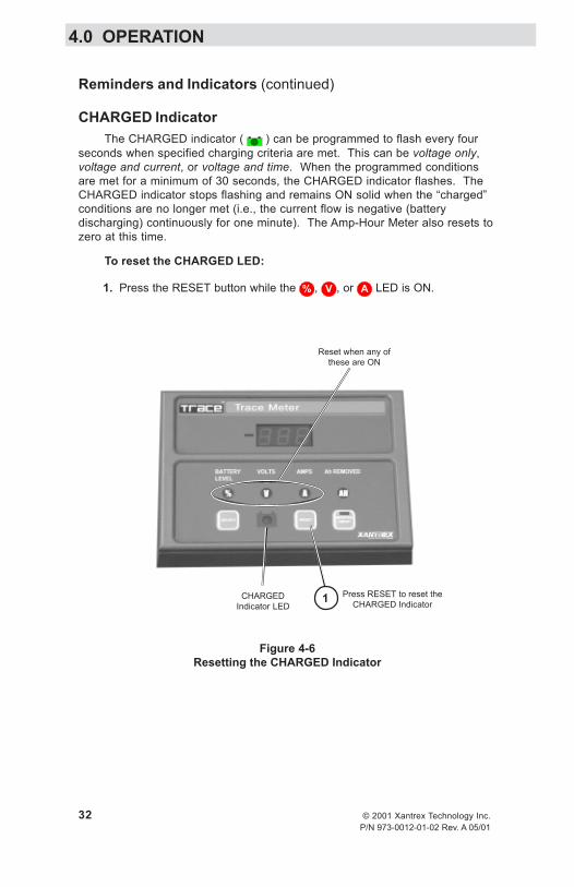
CHARGED IndicatorThe CHARGED indicator ( ) can be programmed to flash every four
seconds when specified charging criteria are met. This can be voltage only,voltage and current, or voltage and time. When the programmed conditionsare met for a minimum of 30 seconds, the CHARGED indicator flashes. TheCHARGED indicator stops flashing and remains ON solid when the “charged”conditions are no longer met (i.e., the current flow is negative (batterydischarging) continuously for one minute). The Amp-Hour Meter also resets tozero at this time.
To reset the CHARGED LED:
1. Press the RESET button while the % , V , or A LED is ON.
CHARGEDIndicator LED
Reset when any ofthese are ON
Figure 4-6Resetting the CHARGED Indicator
Press RESET to reset theCHARGED Indicator1
4.0 OPERATION

© 2001 Xantrex Technology Inc. 33P/N 973-0012-01-02 Rev. A 05/01
motpmyS esuaCelbissoP noituloS
FFO/NORETREVNIniDEL.thgiltonseodhctiws
otnideggulptongulp2J.retrevniehtroA005MT
aevahtonseodretrevnI.kcaJelbatapmoc
dnaA005MTotnielbacgulPetomer8CR/4CRs'retrevnI
.kcajlortnoc
lortnocetomerretrevniehTsledomnosetarepoylno
8CR/4CRnahtiwdeppiuqe.tupnilortnocetomer
nodeyalpsidegatloV.tcerroctonsisretem
siegatlovA005MTehTstlov0.53evobaderugifnoc.metsystlov-42ro-21arof
siegatlovA005MTehTstlov0.53wolebderugifnoc
.metsystlov-84arof
rofA005MTehterugifnoceRegatlovmetsystcerroceht
,3noitceSees(degrahC,noitarugifnoC
.)pu-teSrotacidnI
egrahC-fo-etatSyrettaBnehw"LLUF"syalpsid
.wolsiegatlov
.wolootsignittesruoh-pmA otsruohpmaehterugifnoceRyrettaB-gnittestcerroceht
,3noitceSees(ezisknabgnitteS,noitarugifnoC
.)sruoHpmA,sretemaraP
foegatlovasyalpsidOLb.0.00
tonsawretemOLbehTro,pu-tesgnirudderugifnoc
detcennocsidgniebretfa.tnuhsehtmorf
egatloV-woLehterugifnoceRtcerrocehtrof)OLb(rotacidnI
ees(egatlovyrettab-wol,noitarugifnoC,3noitceS-woL,sretemaraPgnitteS
.)rotacidnIegatloV
seunitnocDELDEGRAHCehthguohtnevehsalfot
evitagensiwolftnerruc)gnigrahcsidyrettab(
.etunimenorofylsuounitnoc
YLNOEGATLOVehtrofnoitarugifnoc
puteSrotacidnIdegrahC.woloottesebyam
DEGRAHCehterugifnoceRetairporppanaotegatlov
arofV6.21,.e.i(eulavnoitceSees(,)metsystlov-21
gnitteS,noitarugifnoC,3degrahC,sretemaraP
.)puteSrotacidnI
rotacidniDEGRAHCehTnrutotteseryllaunamebtsum
.FFOti
A100-D-2100-379
5.0 TROUBLESHOOTING

34 © 2001 Xantrex Technology Inc.P/N 973-0012-01-02 Rev. A 05/01
Xantrex Technology Inc., takes great pride in its products and makesevery effort to ensure your unit fully meets your independent poweringneeds.
If your product needs repair, contact our Customer Service departmentat: (360) 435-8826 to obtain an RMA# and shipping information; or, fax thispage with the following information to: (360) 474-0616. Or contact theXantrex Warranty Department at [email protected].
Please provide:
Model Number: _________________________________
Serial Number: _________________________________
Purchase Date: _________________________________
Problem: ______________________________________
Include a telephone number where you can be reached during businesshours and a complete return shipping address (P.O. Box numbers are notacceptable).
Name: __________________________________________
Address: ________________________________________
City: ___________________________________________
State / Province: __________________________________
Zip / Postal Code: _________________________________
Country: ________________________________________
Phone: (____) ____________________________________
FAX: (____) _____________________________________
E-mail Address: ___________________________________
visit our website at: www.xantrex.comor e-mail us at: xantrex.com
6.0 SERVICE INFORMATION

©2001 Xantrex Technology Inc. 35P/N 973-0012-01-02 Rev. A 05/01
Specifications
Function Range Accuracy
Battery Volts 8.0–35 volts ± 0.1 volt16.0–70 volts ± 0.2 volt
Battery Amps 0.1–999 amps ± 1.5%(+ least significant digit)
Battery Amps Resolution0.1 to 99.9 amps ± 0.1 amp100 to 999 amps ± 1.0 amp
Battery Level % Low (< 27.5%) ~ 2.5% accuracy30–90% in 5% incrementsFULL (> 92.5%)
Current DrawPower Saving Mode 18 mA maximumAll other modes 32 mA maximum
Amp Hours -0.00 to ±167,000 amp hoursBattery Capacity 10 to 2550 amp hours
Data Monitoring FunctionsdSF–Days Since Full 0.01–655 dayscAH–Cumulative Ah Removed 0–999,000 in nonvolatile memorybHI–Battery High Volts to 35.1 VDC resettable (12–24 VDC)
to 70.2 VDC (w/optional 48 VDC adaptor)bLO–Battery Low Volts 8.0 volts, resettable (12–24 VDC)
16.0 volts, resettable (w/48 VDC adaptor)
LED Display 3-digit, 7-segment red LEDwith 5 additional indicators
LED IndicatorsState of Charge(SOC)/Battery EfficiencyBattery VoltageAmpsAmp Hours Removed/Battery CapacityRecharge Reminder (adjustable)Low Battery Voltage (adjustable)
Dimensions 3-7/8" H x 5-3/8" W x 1-1/4" D(14 cm H x 9.5 cm W x 3.2 cm D)
Weight approximately 3 lb (1.36 kg)
MountingSurface using molded plastic adaptorFlush using plastic mounting bracket
Specifications @ 25 °C.Specifications subject to change without notice.
7.0 SPECIFICATIONS

36 © 2001 Xantrex Technology Inc.P/N 973-0012-01-02 Rev. A 05/01
Limited Warranty
Xantrex Technology Inc., warrants its power products against defects inmaterials and workmanship for a period of two (2) years from the date of purchase,established by proof of purchase or formal warranty registration, and extends thiswarranty to all purchasers or owners of the product during the warranty period.Xantrex does not warrant its products from any and all defects:
arising out of material or workmanship not provided by Xantrex orits Authorized Service Centers;when the product is installed or exposed to an unsuitable environment asevidenced by generalized corrosion or biological infestation;resulting from abnormal use of the product, alteration, or use in violation of theinstructions;in components, parts, or products expressly warranted by another manufacturer.
Xantrex agrees to supply all parts and labor to repair or replace defectscovered by this warranty with parts or products of original or improved design, atthe company's option. Xantrex also reserves the right to improve the design of itsproducts without obligation to modify or upgrade those previously manufactured.Defective products must be returned to Xantrex or its Authorized Service Center inthe original packaging or equivalent. The cost of transportation and insurance onitems returned for service is the responsibility of the customer. Return transporta-tion (UPS Ground or equivalent) as well as insurance on all repaired items is paidby Xantrex.
All remedies and the measure of damages are limited to the above. Xantrexshall in no event be liable for consequential, incidental, contingent, or specialdamages, even if Xantrex has been advised of the possibility of such damages.Any and all other warranties, expressed or implied, arising by law, course ofdealing, course of performance, usage of trade or otherwise, including, but notlimited to, implied warranties of merchantability and fitness for a particularpurpose, are limited in duration for a period of two (2) years from the original dateof purchase.
Some states or countries do not allow limitations on the term of an impliedwarranty, or the exclusion or limitation of incidental or consequential damage,which means the limitations and exclusions of this warranty may not apply to you.Even though this warranty gives you specific legal rights, you may also have otherrights which vary from state to state.
5916 - 195th Street N.E., Arlington, WA 98223 Phone: (360) 435-8826 Fax: (360) 435-2229
visit our website at: www.xantrex.com
8.0 WARRANTY


Xantrex Technology Inc.5916 195th NortheastArlington, WA 98223U.S.A.t: 360/435.8826f: 360/435.3945www.xantrex.com Printed in U.S.A.
© 2001 Xantrex Technology Inc.
P/N 973-0012-01-02 Rev. A 05/01