industrial battery chargers list prices & policies€¦ · industrial battery chargers list...
TRANSCRIPT

4328 Bridgeton Industrial Dr. Bridgeton, MO 63044 Tel. (314) 739-1414 Fax.(314) 739-1277
Industrial Battery ChargersList Prices & Policies
FERRO MAGNETICS CORPORATION

Ferro Magnetics Corporation Price and Policy Catalog
Price & Policies Catalog
TABLE OF CONTENTS
1. Introduction ContactsProduct descriptions
2. Ordering information & procedures Order Form
3. Charger Controls
4. 80% ~ 8 hour H Series Charger
5. 100% ~ 8 hour X Series Charger
6. 100% ~ 6 hour XR Series Charger
7. Controlled Chargers Controlled P Series 100% ~ 8 hour or less Controlled R Series 100% ~ 5.5 hour or less Green Machine – High Frequency chargers
8. 100% Mine Chargers
9. Specialty Chargers 16 hour ST Chargers Top Mount Chargers Constant Current Charger Multi Cell Charger
10. Options / Accessories / Kits Factory Installed Options AccessoriesTobi Management System Watering System Components Control Retrofit-Kits Application Analysis Tools & Battery Modules
11. Parts
12. Warranty

Ferro Magnetics Corporation Standard Operating Procedures 1
General
INTRODUCTION
Welcome Ferro Magnetics Corporation has been manufacturing private-brand industrial battery chargers since 1974. Ferro backs its products with our strength in development and design of industrial electronics, magnetics, and complete cabinetry as well as having a dedicated team to support your sales and service needs. We are pleased to have the opportunity to serve your company and are confident we will meet your growth needs through the years.
Introduction This price-sheet catalog contains all of the standard product lines currently manufactured by Ferro Magnetics Corp. All charger products that we manufacture are built in accordance with BCI (Battery Council International) standards. Most lines carry a UL and cUL listing. Charger designs or ratings not shown in this catalog may be designed and built to customer specifications based on quantity for many applications or battery types. Ferro Magnetics is very flexible in manufacturing techniques and possesses many years of engineering expertise in charger design. Please contact us for details and pricing.

Ferro Magnetics Corporation Standard Operating Procedures 2
FERRO MAGNETICS CONTACTS
Tel. 314-739-1414 Fax. 314-739-1277 General E-mail. [email protected] Sales & Marketing Rex Palmatier [email protected]
Connie VanHorn [email protected]
Technical Assistance / Engineering Tim Mallet [email protected] Chris Potts [email protected]
Accounts Receivable
Paula Gonzalez [email protected] Accounts Payable
Paula Gonzalez [email protected]

Ferro Magnetics Corporation Price and Policy Catalog 3
PRODUCT DESCRIPTIONS
Various Charge Parameters
o Recharge Times - 2 hours to 16 hours
o Starting Rates - The standard start rates for the most common charger lines are: XR=25 amps per hundred, XP=18 amps per hundred, HP=14.7 amps per hundred, ST/TSS=6.6 amps per hundred.
o Finish Rates - A finish rate of 4.5% at 2.6 volts per cell is standard on the HP and XP ferro resonant models, 4% is standard on the ST and TM models. 5% at 2.6 volts per cell is standard on controlled product.
o AC Voltages - From 120 to 600 as standard, custom voltages available up to 1500.
o AC Hz.- 60 & 50 Hz
o Cells - 1 to 162 Lead Acid or 1 to 270 Ni-Cad (UL & cUL Listed) Chargers for a higher number of cells available, consult factory
o Discharge Standard- HP - 80% Discharged @ 6 Hour Rate XP - 100% Discharged @ 6 Hour Rate XR - 100% Discharged @ 6 Hour Rate
o Chargers for other rates available, consult factory
Motive Power Charger Model Prefixes
Product Line H Series
[8 hr / 80%]
Single Ph Three Ph
X Series [8 hr / 100%]
Single Ph Three Ph
Rapid Recovery [6 hr / 100%]
Single Ph Three Ph
Ferro-Resonant HPS HPT XPS XPT - XRT
Controlled Ferro - - CPS CPT - CRT
Mine Skid - - - MSP - MSR
High Frequency - - XHF XHF RHF RHF
Product Line
16 hr / 80%
Single Ph Three Ph
Fixed Output
Single Ph Three Ph
Constant Current - - LS/CCS CCSSweet Sixteen ST - -
Top Mount TSS - - -

Ferro Magnetics Corporation Price and Policy Catalog 4
Product Line Definitions Ferro-Resonant H Series (HPS, HPT)
HP (80% in 8 hours) The HP charger line will recharge a flooded lead acid battery in 8 hours, of matched amp-hour size that has been discharged 80% at the 6-hour discharge rate. This charger is designed for two or three shift application. The Ferro-Resonant HP model has a starting rate, at nominal AC line, of 14.7 amps output for each 100 amp-hour size of the charger rating. The finish rate is 4.5 amps output for each 100 amp-hour size of the charger rating at 2.6 VPC (+/-1% with a line variation of +10/-6%). The start and finish rates are fixed. (UL and cUL listed)
Ferro-Resonant X Series (XPS, XPT)
XP (100% in 8 hours) The XP charger line will recharge a flooded lead acid battery in 8 hours of matched amp-hour size that has been discharged 100% at the 6-hour discharge rate. This charger is primarily designed for two or three shift application. The 100% XP model will handle applications where customers do not follow battery manufacturers' warranty recommendations of discharging the battery only to 80% depth of discharge. The customer may also want the security of handling occasional peak production periods. The Ferro-Resonant Premium model has a starting rate, at nominal AC line, of 18 amps output for each 100 amp-hour size of the charger rating. The finish rate is 4.5 amps output for each 100 amp-hour size of the charger rating at 2.6 VPC (+/-1% with a line variation of +10/-6%). The start and finish rates are fixed. (UL and cUL listed) Ferro-Resonant Rapid Recovery Line (XRT) XR (100% in 6 hours) The FR charger line will recharge, in 6 hours, a flooded lead acid battery of matched amp-hour size that has been discharged 100% at the 6-hour discharge rate. This charger is ideal for very abusive three shift and cold storage applications. Customers may want the security of handling occasional peak production periods. The Rapid Recovery model has a start rate, at nominal AC line, of 25 amps output for each 100 amp-hour size of the charger rating. The finish rate is 4.5 amps output for each 100 amp-hour size of the charger rating or 2.6 VPC (+/-1% with a line variation of +10/-6%). The start and finish rates are fixed.(UL and cUL listed)
Ferro Magnetics Corporation Price and Policy Catalog 5
Controlled Ferro Line (CP, CR & CFD)
The Controlled Ferro is designed for those applications where regulation of the charger’s output is required, such as manufacturer’s specific profiles for sealed batteries. The Controlled Ferro line is provided with the 046-0272 control. (UL and cUL listed) CP (100% in 8 hours) The CP charger is designed to charge a 100 % discharged sealed or flooded lead-acid battery of matched size within 8 hours. The start rate at nominal AC line is regulated at 18 amps output for each 100 amp-hour size of the charger rating. The finish rate is regulated at 5 amps output [standard for the flooded battery algorithm] for each 100 amp-hour size of the charger rating at 2.6 VPC. The charging profile is pre-set by selectable algorithms within the control board. The algorithms are based on battery manufacturer’s charge profile specifications. CR (100% in 6 hours) The CP charger is designed to charge a 100 % discharged sealed or flooded lead-acid battery of matched size within 6 hours. The start rate at nominal AC line is regulated at 25 amps output for each 100 amp-hour size of the charger rating. The finish rate is regulated at 5 amps output [standard for the flooded battery algorithm] for each 100 amp-hour size of the charger rating at 2.6 VPC. The charging profile is pre-set by selectable algorithms within the control board. The algorithms are based on battery manufacturer’s charge profile specifications. CFD (100% in 3 hours) The CFD charger is designed to charge a 100 % discharged flooded lead-acid battery of matched amp hour size within 3 hours. The start rate at nominal AC line is regulated at 50 amps output for each 100 amp-hour size of the battery up to the maximum amp rating of the charger. The finish rate is regulated at 5 amps output [standard for the flooded battery algorithm] for each 100 amp-hour size of the charger rating at 2.6 VPC. The charging profile is pre-set by selectable algorithms within the control board. The algorithms are based on battery manufacturer’s charge profile specifications. Mine-Skid Line (MSP, MSR) The Mine Skid chargers are standard ferro-resonant skid/sled mounted chargers designed for abusive application where mobility is needed; such as underground mining, construction sites, tunneling operations, oilrigs, railroad yards, etc. The charger is constructed on a structural steel sled that can be towed to the point of use. The standard models are the MSR, (Mine Skid Rapid Recovery), and the MSP, (Mine Skid Premium). This charger is supplied standard with 15 feet of DC cable, without a connector. The MSR charger is designed to charge a 100 % discharged flooded lead-acid battery of matched size within 6.5 hours. Typical start rate at nominal AC line is 21 amps output for each 100 amp-hour size of the charger rating. The MSP charger is designed to charge a 100 % discharged flooded lead-acid battery of matched size within 8 hours. Typical start rate at nominal AC line is 16.6 amps output for each 100 amp-hour size of the charger rating. The finish rate for both models is 4 amps output for each 100 amp-hour size of the charger rating or 2.6 VPC (+/-1% with a line variation of +10/-6%). The start and finish rates are fixed.

Ferro Magnetics Corporation Price and Policy Catalog 6
Constant-Current Loaner (LS) The LS (Loaner Charger) is a universal ferro-resonant charger, with fixed constant current output of 28 amps. It will charge any cell combination within 2 to 24 cells at the constant current rating specified on the nameplate. With an automatic control, this unit is ideal for rental fleets and as a loaner charger. The design provides the ease of stocking a single charger to charge several battery sizes. The charger is mounted on a sturdy wheeled cart for ease of transportation and use. Input voltage is 120 single-phase and draws a maximum of 15 amps, so it can be plugged into any standard AC wall outlet. Charge time is based on amp-hour size of the battery connected and D.O.D. Constant- Current Shop (CCS)
The CCS models are designed for higher output current requirements. These models are available in both single and three phase. Because of the AC input current draws needed; these chargers are typically used in a fixed location and hard wired to the building AC service. The CCS line is available with automatic control or mechanical timer. The constant current chargers are designed to have a nearly flat charge curve. The output will taper only slightly in order to maintain the AC amp draw as the battery voltage rises Sweet Sixteen (ST) The ST chargers are standard ferro-resonant designed to charge an 80 % discharged flooded lead-acid battery, at the 6-hour discharge rate, of matched size within 16 hours. Typical start rate at nominal AC line is 6.6 amps output for each 100 amp-hour size of the charger rating. The finish rate is 4.5 amps output for each 100 amp-hour size of the charger rating at 2.6 VPC (+/-1% with a line variation of +10/-6%). The start and finish rates are fixed. The ST model is built in a non-accessible light duty cabinet and single-phase configuration only.
Top Mount (TSS) The Top Mount is designed to be mounted on the top of the battery tray or on the vehicle which contains the battery. This charger is available in 16 hour models and is designed to recharge an 80% discharged battery. Chargers are available in single phase set-voltage only.

Ferro Magnetics Corporation Price and Policy Catalog 7
Charger Model Numbering System XPS6-180K – 2 XP S 6 - 180 K - 2
# circuits if more than 1
AC Volt Code
A. Hrs
# Cells
Phase
Type
Type: Standard Ferro: HP = 80%~8hr / XP = 100%~8hr / XR = 100%~6.5hr Controlled Ferro: CP = 100%~8hr / CR=100%~6.5hr Phase: S = Phase (S=Single / T=Three Phase) Voltage Codes: (A= 120/208/240, B=208/240/480, etc. see voltage code chart) A through AZ for 60Hz or 50Hz applications
AC Voltage Code
Code AC Volts Hz * A 120 / 208 / 240 60 B 208 / 240 / 480 60 C 120 60 D 240 60 E 480 60 K 480 / 575 60
* 50Hz applications consult factory for information NOTE: A, C & D codes are for Single Phase only

Ferro Magnetics Corporation Price and Policy Catalog 8
AC cord sets on factory shipped chargers Chargers requiring cord sets for 120 VAC input operation are shipped with the following plugs: For 15-amp draw or less, a standard 15 amp NEMA 5-15P-type plug will be installed. For 15.1 amps to 30 amps draw, a 30 amp NEMA L5-30P type plug will be installed.
If your customer requests a special type plug other than our standard configuration, please consult the factory. Cabinet Configurations 500 Series Cabinet The following figures represent the standard 500 case configurations for the following product lines:
Ferro-Resonant • Controlled Ferro-Resonant • Constant Current Ferro-Resonant The amp-hour rating and voltage of the charger determine which cabinet size is used.
1714
2012
26
2414
28
3814
H X W X D500 - 201
2 X 1714 X 143
4501 - 26 X 241
4 X 2458
502 - 28 X 3814 X 275
8
501500
502
Ferro Magnetics Corporation Price and Policy Catalog 9
Gang Unit
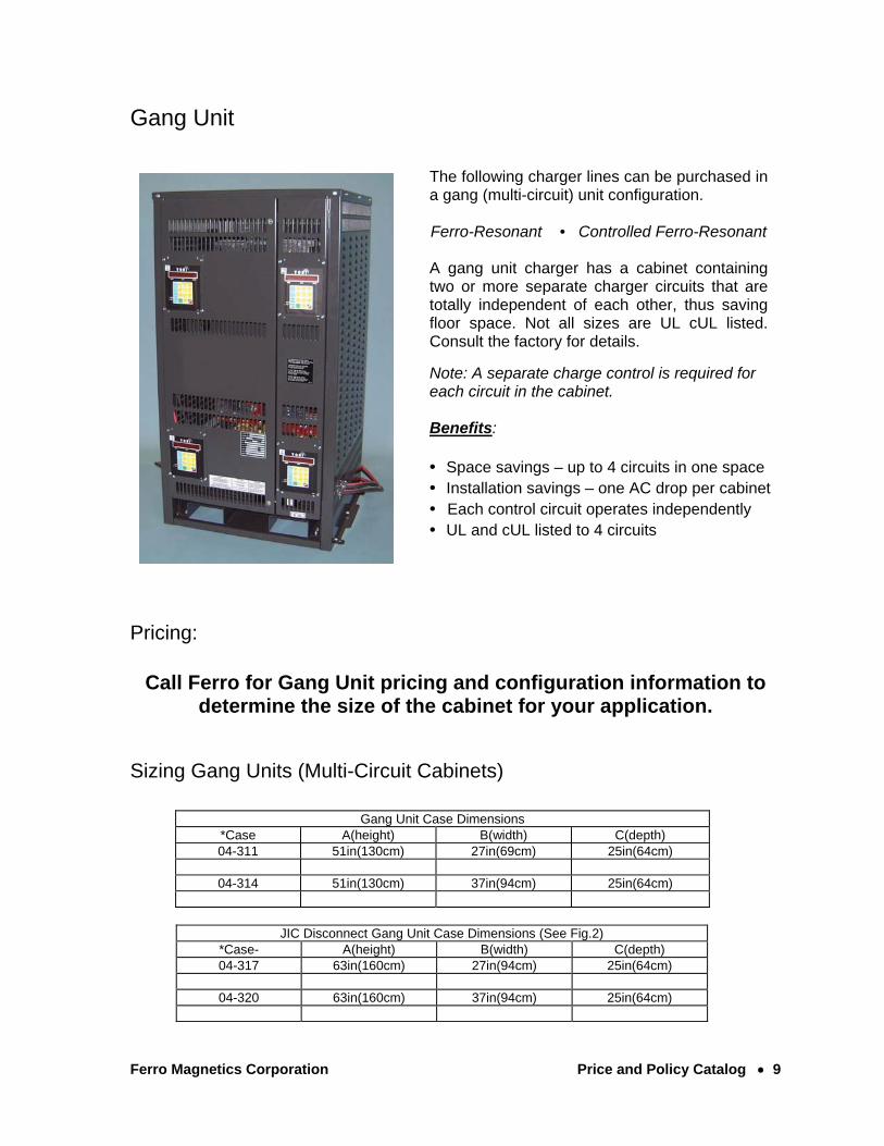
The following charger lines can be purchased in a gang (multi-circuit) unit configuration. Ferro-Resonant • Controlled Ferro-Resonant A gang unit charger has a cabinet containing two or more separate charger circuits that are totally independent of each other, thus saving floor space. Not all sizes are UL cUL listed. Consult the factory for details. Note: A separate charge control is required for each circuit in the cabinet.
Benefits:
• Space savings – up to 4 circuits in one space • Installation savings – one AC drop per cabinet • Each control circuit operates independently • UL and cUL listed to 4 circuits
Pricing:
Call Ferro for Gang Unit pricing and configuration information to determine the size of the cabinet for your application.
Sizing Gang Units (Multi-Circuit Cabinets)
Gang Unit Case Dimensions *Case A(height) B(width) C(depth) 04-311 51in(130cm) 27in(69cm) 25in(64cm)
04-314 51in(130cm) 37in(94cm) 25in(64cm)
JIC Disconnect Gang Unit Case Dimensions (See Fig.2) *Case- A(height) B(width) C(depth) 04-317 63in(160cm) 27in(94cm) 25in(64cm)
04-320 63in(160cm) 37in(94cm) 25in(64cm)

Ferro Magnetics Corporation Price and Policy Catalog 10
Gang Unit Case (Fig.1)
TOBITOBI
TOBITOBI
CB
18.000
B -28.375
A
A - 04-314
B - 04-311

Ferro Magnetics Corporation Price and Policy Catalog 11
JIC Disconnect Gang Unit (Fig.2)
TOBITOBI
TOBITOBI
CB
18
.0
00
A
B -28.375
-38.375
BASE MOUNTING DIMENSIONS:
A
A - 04-320
B - 04-317

Ferro Magnetics Corporation Price and Policy Catalog 12
Sweet Sixteen (ST)
14.000 10.625
10
.7
50
FRONT SIDE BACK
CONTROL
Top Mount (TSS)

Section 2
Ferro Magnetics Corporation Price and Policy Catalog 1
Order Information & Procedures
GENERALFerro Magnetics must receive orders in writing. They may be mailed, faxed, Emailed, or downloaded via computer. All orders are handled and filled on a first-in first-out basis, regardless as to size of order, or sales volumes of the purchaser. All cancellation requests must be received in writing.
[email protected] Fax. 314-739-1277 Tel. 314-739-1414
PROCEDURESOrders should be entered on the Ferro Magnetics order form sheet or use this sheet as a guide for the minimal information required to process the order correctly. This sheet may be mailed, emailed or faxed to us. All necessary information must be filled in, including any special instructions or requests for options. An agent profile will be kept, that details the standard order information initially established at the conception of the working relationship. A copy of the order form is included in this section. It can be used to make copies. Agents will receive a Faxed confirmation from Ferro showing scheduled ship dates, product ordered, special options and instructions as well as any corrections to part numbers/pricing.
SHIPPINGChargers will be shipped via a common carrier designated by Ferro Magnetics unless stated other wise by agent. Shipping is pre-paid F.O.B. St. Louis to the first destination within the continental USA except for ST/TM models, mine chargers and gang units.
SHIPPING DAMAGE Any shipping damage claims must be handled between the carrier, and the consignee. It is the responsibility of the consignee to closely examine the charger cabinet for any concealed damages.

Section 2
Ferro Magnetics Corporation Price and Policy Catalog 2
CANCELLATIONS Cancellation of orders will be handled as follows:
a. Four weeks prior to shipment - No Charge b. Three weeks prior to shipment - 25% of Order c. Two weeks prior to shipment - 50% of Order d. No credit given after charger has shipped
NOTE: Any non-standard chargers or materials that have been special ordered for an order that is canceled, and that cannot be returned to a supplier for credit, will be shipped and invoiced to the purchaser. All cancellation requests must be received in writing.
QUOTESFerro Magnetics will be pleased to quote prices on large quantity, custom designed or odd sized chargers. To protect everyone's best interest, quotes will only be given in writing to personnel pre-authorized by the agent. Unless otherwise approved and noted on the written quote, quotes expire after 30 days.
TAXESIn order to comply with the majority of state and local sales tax law requirements, it is necessary to have in our files a properly executed exemption certificate from all our distributors who claim sales tax exemption. An example of this form is shown below.

Ferro Magnetics Corporation • PO Box 4039 • Hazelwood, MO • 63042Rev. 6.03
FERRO MAGNETICS CORP. ~ SALES ORDERPhone 314-739-1414 • Fax. 314-739-1277 • [email protected]
BILL TO: DATE:
ADDRESS: PO#:
CITY/ST/PROV: ZIP/POST CODE:
Phone: Fax:
Order Written By: Quick Ship: ?NOTE: All orders and cancellations must be submitted by fax or e-mail
CHARGER:Qty: Model No: Control:
Input Voltage Range: / / Set At: Hertz: Phase: Connector: Cabinet Size: Battery Type:
Special Instructions:
Requested Ship Date:
TOTAL NET CHARGER PRICE:
OPTIONS:
Qty: Option No: Description: Net Price: Qty: Option No: Description: Net Price: Qty: Option No: Description: Net Price:
TOTAL NET OPTIONS PRICE:
SHIPPING INSTRUCTIONS:SHIP TO:
ADDRESS:
CITY/ST/PROV: ZIP/POST CODE:
MARK SHIPMENT [Att: or PO #]:
Section 3
Ferro Magnetics Corporation Price and Policy Catalog 1 rev 4.10
Charger Controls
CONTROL MODELSThere are three basic controls available not including the mechanical timer (28-11) that is sometimes used on mine application chargers. The complexity and capabilities of the controls goes from competitive level (046-0166), to the standard-features level (046-0271), and the top-end level (046-0272). The Charge Control (046-0166) is currently only available on the 16 hour Sweet Sixteen (ST) and Top Mount (TSS) chargers.
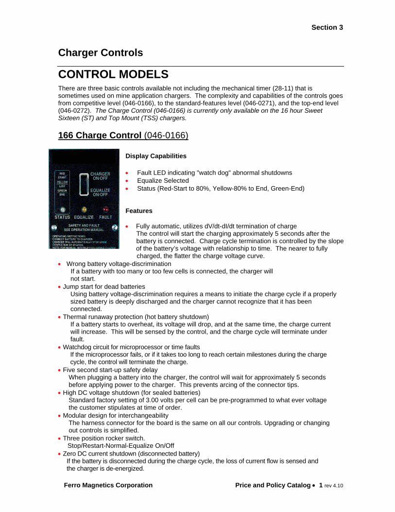
166 Charge Control (046-0166)
Display Capabilities
Fault LED indicating "watch dog" abnormal shutdowns Equalize Selected Status (Red-Start to 80%, Yellow-80% to End, Green-End)
Features
Fully automatic, utilizes dV/dt-dI/dt termination of charge The control will start the charging approximately 5 seconds after the battery is connected. Charge cycle termination is controlled by the slope of the battery’s voltage with relationship to time. The nearer to fully charged, the flatter the charge voltage curve.
Wrong battery voltage-discrimination If a battery with too many or too few cells is connected, the charger will not start. Jump start for dead batteries
Using battery voltage-discrimination requires a means to initiate the charge cycle if a properly sized battery is deeply discharged and the charger cannot recognize that it has been connected. Thermal runaway protection (hot battery shutdown)
If a battery starts to overheat, its voltage will drop, and at the same time, the charge current will increase. This will be sensed by the control, and the charge cycle will terminate under fault.
Watchdog circuit for microprocessor or time faults If the microprocessor fails, or if it takes too long to reach certain milestones during the charge cycle, the control will terminate the charge.
Five second start-up safety delay When plugging a battery into the charger, the control will wait for approximately 5 seconds before applying power to the charger. This prevents arcing of the connector tips.
High DC voltage shutdown (for sealed batteries) Standard factory setting of 3.00 volts per cell can be pre-programmed to what ever voltage the customer stipulates at time of order.
Modular design for interchangeability The harness connector for the board is the same on all our controls. Upgrading or changing out controls is simplified.
Three position rocker switch. Stop/Restart-Normal-Equalize On/Off
Zero DC current shutdown (disconnected battery) If the battery is disconnected during the charge cycle, the loss of current flow is sensed and the charger is de-energized.
CHARGE CONTROL

Section 3
Ferro Magnetics Corporation Price and Policy Catalog 2 rev 4.10
271 Control (046-0271)
Display Capabilities LED/LCD display test at startup Digital LCD display Charging, Complete and Fault LED’s Digital LCD readout indicating ten numeric fault codes Delayed Start time remaining End of charge Voltage (VPC), Amps, Run time, Total Amp-hours, % returned, End voltage, End Amps
Features Fully automatic, utilizes dV/dt-dI/dt termination of charge
The control will start charging approximately 5 seconds after the battery is connected. Charge cycle termination is controlled by the slope of the battery’s voltage with relationship to time.
The nearer to fully charged, the flatter the charge voltage curve. Wrong battery voltage-discrimination If a battery with too many or too few cells is connected, the charger will not start.
Jump start for dead batteries Using battery voltage-discrimination requires a means to initiate the charge cycle if a properly sized battery is deeply discharged and the charger cannot see it.
Thermal runaway protection (hot battery shutdown) If a battery starts to overheat, its voltage will drop, and at the same time, the charge current will increase. This will be sensed by the control, and the charge cycle will terminate.
Watchdog circuit for microprocessor or time faults If the microprocessor fails, or if it takes too long to reach certain milestones during the charge cycle, the control will terminate the charge.
High DC voltage shutdown Factory setting of 2.80 volts per cell
Timed delay start (0-24:00). Delays charge until after AC Peak Demand Periods settable in 1 minute increments.
Zero DC current shutdown (disconnected battery) If the battery is disconnected during the charge cycle, the loss of current flow is sensed and the charger is de-energized.
Manual/Auto equalize (by number of cycles) In addition to the manual equalize keypad button, an automatic equalize by charge cycles (settable 1-30) is settable.
Refresh (automatic re-charge cycling) Allows the charger to cycle on and refresh the battery as long as it remains connected to the charger; settable from 0-72:00. Refresh cycles will not add to auto Equalize count.
Membrane Keypad Buttons (Eliminates broken switches) Programmable for simple setup

Section 3
Ferro Magnetics Corporation Price and Policy Catalog 3 rev 4.10
272 Control (046-0272)
Display Capabilities
LED/LCD digital display test at startup Accumulated amp-hours, amps output, volts per cell, volts, % returned Total time of charge to present, or to end of charge Time of day, delayed-start time Faults and errors Equalize mode set. Current Mode of Charger
Features Fully automatic, utilizes dV/dt-dI/dt termination of charge. The control will start the charging approximately 5 seconds after the battery is connected. Charge cycle termination is controlled by the slope of the battery’s voltage with relationship to time. The nearer to fully charged, the flatter the charge voltage curve. Wrong battery voltage-discrimination. If a battery with too many or too few cells is connected to the charger it will not start. Jump start for dead batteries. Using battery voltage-discrimination requires a means to initiate the charge cycle if a properly sized battery is so discharged that the charger does not see it. Battery thermal protection The 272 control has a hardwire thermistor capability as well as the capability to receive the battery temperature from the TOBi PI. The 272 control has three separate settable temperature protection points; Okay to charge, low charge rate and No charge. Watchdog circuit for microprocessor and timed faults. If the microprocessor fails, or if it takes too long to reach certain milestones during the charge cycle, the control realizes it and terminates the charge. High DC voltage shutdown (primarily for sealed batteries). Standard factory setting of 2.80 volts-per-cell can be re-programmed to what ever voltage the customer desires. Timed delay start (0-24:00 hours). Prevents opportunity charging or delays charge until after AC Peak Demand Periods Time-of-day delay start. Delays charge until after AC Peak Demand Periods, programmable by time of day Zero DC current shutdown (disconnected battery). If the battery is disconnected during the charge cycle, the loss of current flow is sensed and the charger is de-energized. Manual/auto equalize (by number of cycles or day of week). In addition to the manual equalize keypad button, a default factory setting of automatic equalize every 7 charge cycles is programmed into the control. It is field changeable from 0 to 30 cycles via the control keypad. Overcharge adjustment (cold storage, undersized AH batteries etc.) Allows adjustment of the end of charge-cycle time Adjustable hysteresis loop (automatic re-charge cycling). Allows the charger to cycle on and off based on a pre-set self discharge point. Capable of automatic watering of the battery. Serial cable-ready for Battery Management System computer TOBi PI communication is by RF signal over the DC cables, the TOBi PI can change the TOBi control programming to meet a custom charge requirement when the TOBi control has battery module communication enabled.