marine battery chargers - installation tips ... battery charger tips an… · marine battery...
TRANSCRIPT
Marine Battery Chargers - Installation Tips & Considerations:
This article written by: RC Collins of Compass Marine Inc. Images in this .pdf copyright of Compass
Marine Service
With battery banks getting larger & larger and battery technology becoming more and more expensive a quality
battery charger is not the place you want to skimp on features or quality.
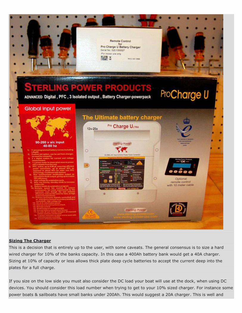
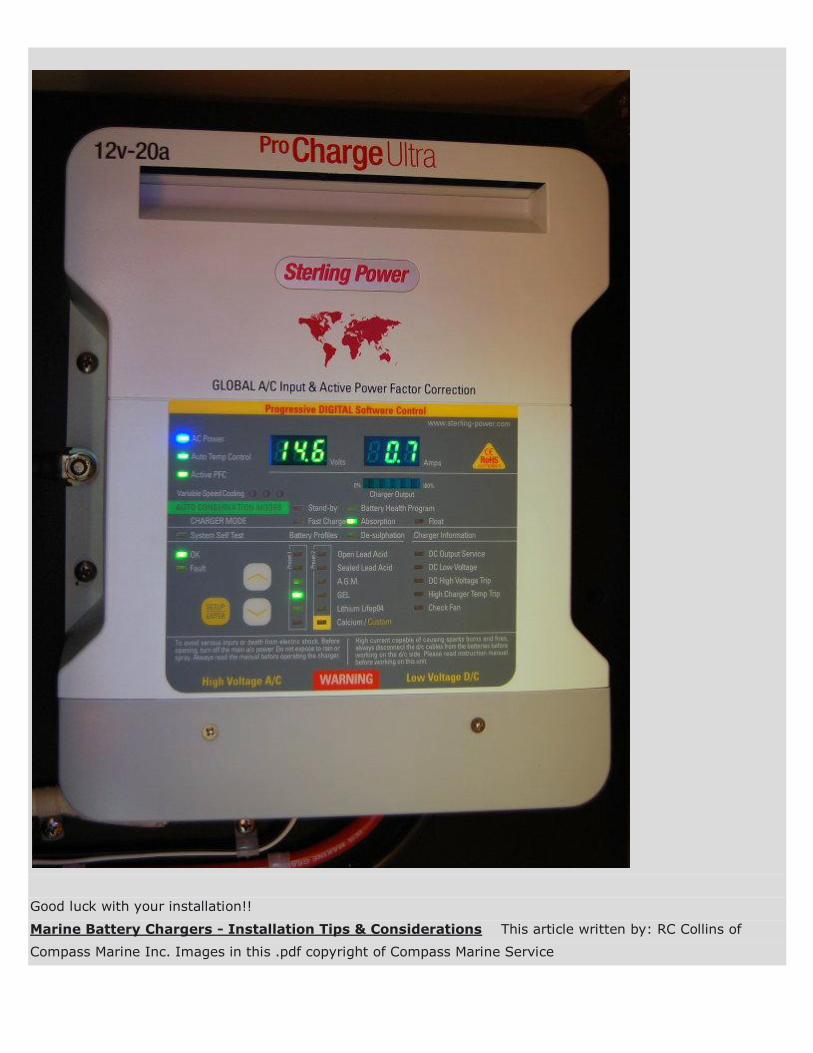
For this article I am installing a Sterling Pro Charge Ultra. When selecting a marine battery charger there are
certain things I find to be important.
1- The charger should be built to ABYC / UL 1236 standards. These standards are specific to the marine
industry, though I think the emergency market such as rescue and ambulance also use UL 1236. This standard
is created around safety and isolation of AC & DC. A UL 1236 charger has undergone a 1500 volt test to ensure
there is adequate AC/DC isolation inside the charger. 1500 VOLTS !!!!! While there are some non-marine
chargers that can do quite well in the marine environment the UL 1236 or "ABYC" compliant statement or logo
will be a good guide and won't leave you guessing if the charger you chose can handle the environment or is
well suited to a marine application.
This quote was published in an ABYC referenced article and written by corrosion survey specialist Stanley Konz.
"WHAT WE FOUND
Ø Burnt and corroded shore power cords
Ø Improper AC Neutral to DC negative connections
Ø Reversed battery cables
Ø The failure of an automatic inverter ground switch
Ø Oversized breakers
Ø A BATTERY CHARGER INPUTTING 110AC INTO THE BATTERIES
Ø Wire nuts used
Ø Undersized wire
Ø Hard (house type) untinned wires"
A BATTERY CHARGER INPUTTING 110AC INTO THE BATTERIES!!!!!!!!!!!!!!!! It is critical you choose a well built
charger and wire it properly. If you don't fully understand the above points made by Mr. Konz you should
consider consulting a qualified marine electrical systems specialist for this install.
That article goes onto say that nearly 1/3 of the boats in that marina were leaking AC current directly into the
water! DIY wiring mistakes, even by those meaning well, can often be a major player in these "leaks". Please
be careful and follow acceptable safety guidelines.
2- The charger should work on varying input voltages and not suffer from output limiting. This Sterling PCU is a
"World Voltage" power factor corrected charger and will work on any voltage from 90-260 volts/ 40-80 hz and
still supply 100% of its rated output. You can plug this charger in to voltages in just about all countries on the
planet. If you're a cruiser this is a critically important feature. If you have a US voltage charger you're stuck
charging at US voltage/hz docks.. There are MANY docks out there with voltage drop issues and even at 90
volts AC, with the Sterling PCU, you're still getting the full rated charger output.
3- The charger should ideally offer battery temperature sensing and come with the sensor as standard
equipment, not an "extra".
4- The charger needs to have a good warranty and the manufacturer should have a good reputation for
customer service/support. This charger carries a 5 year warranty and the Support at Sterling Power USA has
been outstanding.
5- The charger should include multiple options for charging voltages/programs.
6- The charger should be multi-stage with at least Bulk, Absorption, Float. I prefer them to also include a
Conditioning/Equalizing program.
7- The charger should work well with marine generators. Many chargers, especially non-marine units, do not
work well with a marine gen set as the generators do not output a pure sine wave.
8- For charging wet cell batteries I prefer a charger that will revert to an absorption voltage periodically when
left in standby/float mode. This programmed absorption voltage cycle helps to minimize electrolyte
stratification. Float current alone is often not enough to prevent the electrolyte from stratifying. An absorption
voltage, run periodically for a short duration, very often prevents the effects of stratification.
Stratification is when the acid sinks to the bottom of the battery case and the water rises to the top of the
battery case. It creates uneven plate wear and can lead to premature death of the battery. A cyclic absorption
voltage will get the electrolyte moving again and minimize any effects of stratification. Not all chargers offer
this very useful "cyclic absorption" feature.
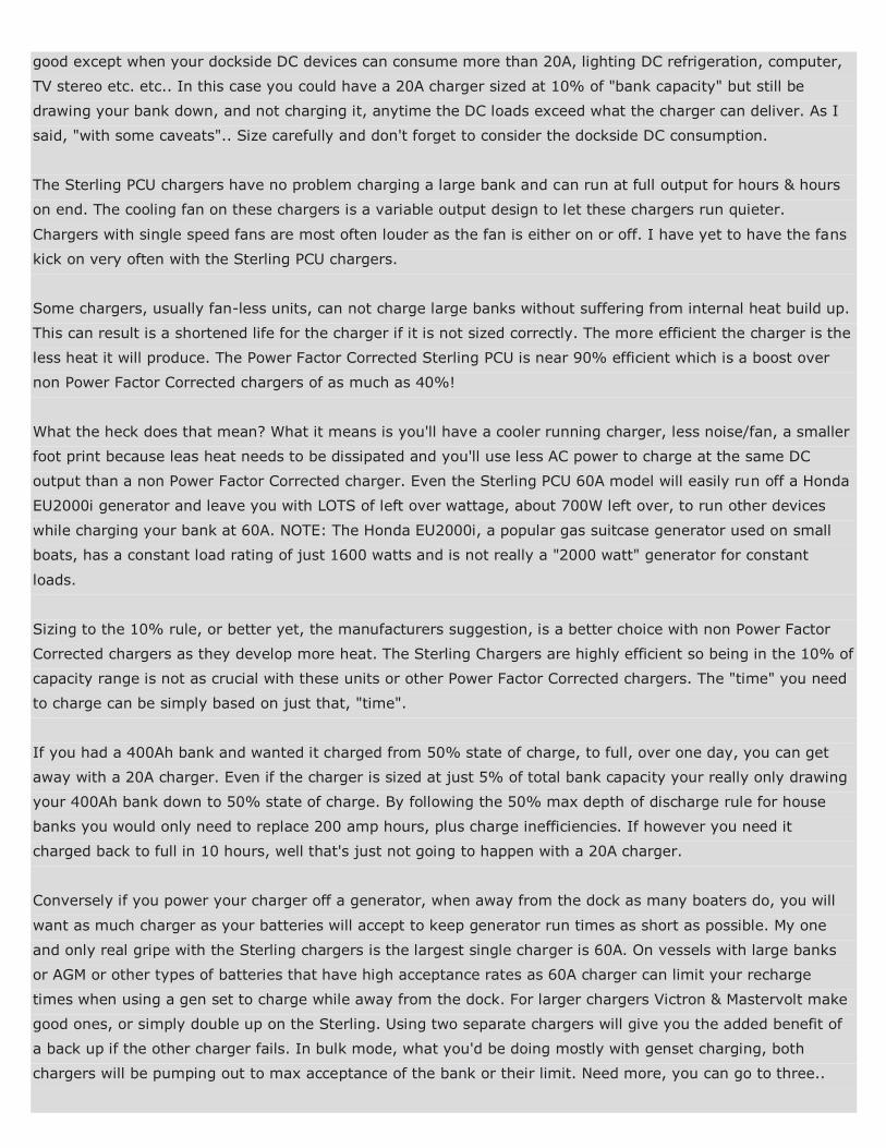
Sizing The Charger
This is a decision that is entirely up to the user, with some caveats. The general consensus is to size a hard
wired charger for 10% of the banks capacity. In this case a 400Ah battery bank would get a 40A charger.
Sizing at 10% of capacity or less allows thick plate deep cycle batteries to accept the current deep into the
plates for a full charge.
If you size on the low side you must also consider the DC load your boat will use at the dock, when using DC
devices. You should consider this load number when trying to get to your 10% sized charger. For instance some
power boats & sailboats have small banks under 200Ah. This would suggest a 20A charger. This is well and
good except when your dockside DC devices can consume more than 20A, lighting DC refrigeration, computer,
TV stereo etc. etc.. In this case you could have a 20A charger sized at 10% of "bank capacity" but still be
drawing your bank down, and not charging it, anytime the DC loads exceed what the charger can deliver. As I
said, "with some caveats".. Size carefully and don't forget to consider the dockside DC consumption.
The Sterling PCU chargers have no problem charging a large bank and can run at full output for hours & hours
on end. The cooling fan on these chargers is a variable output design to let these chargers run quieter.
Chargers with single speed fans are most often louder as the fan is either on or off. I have yet to have the fans
kick on very often with the Sterling PCU chargers.
Some chargers, usually fan-less units, can not charge large banks without suffering from internal heat build up.
This can result is a shortened life for the charger if it is not sized correctly. The more efficient the charger is the
less heat it will produce. The Power Factor Corrected Sterling PCU is near 90% efficient which is a boost over
non Power Factor Corrected chargers of as much as 40%!
What the heck does that mean? What it means is you'll have a cooler running charger, less noise/fan, a smaller
foot print because leas heat needs to be dissipated and you'll use less AC power to charge at the same DC
output than a non Power Factor Corrected charger. Even the Sterling PCU 60A model will easily run off a Honda
EU2000i generator and leave you with LOTS of left over wattage, about 700W left over, to run other devices
while charging your bank at 60A. NOTE: The Honda EU2000i, a popular gas suitcase generator used on small
boats, has a constant load rating of just 1600 watts and is not really a "2000 watt" generator for constant
loads.
Sizing to the 10% rule, or better yet, the manufacturers suggestion, is a better choice with non Power Factor
Corrected chargers as they develop more heat. The Sterling Chargers are highly efficient so being in the 10% of
capacity range is not as crucial with these units or other Power Factor Corrected chargers. The "time" you need
to charge can be simply based on just that, "time".
If you had a 400Ah bank and wanted it charged from 50% state of charge, to full, over one day, you can get
away with a 20A charger. Even if the charger is sized at just 5% of total bank capacity your really only drawing
your 400Ah bank down to 50% state of charge. By following the 50% max depth of discharge rule for house
banks you would only need to replace 200 amp hours, plus charge inefficiencies. If however you need it
charged back to full in 10 hours, well that's just not going to happen with a 20A charger.
Conversely if you power your charger off a generator, when away from the dock as many boaters do, you will
want as much charger as your batteries will accept to keep generator run times as short as possible. My one
and only real gripe with the Sterling chargers is the largest single charger is 60A. On vessels with large banks
or AGM or other types of batteries that have high acceptance rates as 60A charger can limit your recharge
times when using a gen set to charge while away from the dock. For larger chargers Victron & Mastervolt make
good ones, or simply double up on the Sterling. Using two separate chargers will give you the added benefit of
a back up if the other charger fails. In bulk mode, what you'd be doing mostly with genset charging, both
chargers will be pumping out to max acceptance of the bank or their limit. Need more, you can go to three..

Sizing can be a personal preference often based on how "quickly" you need to replenish the bank or
necessitated by the charger you choose and its abilities. Deep cycle batteries like to be slow charged, so if your
alternator is large, then it may make sense to have a smaller 120V charger for good deep slow charges of your
bank. With boats we often don't have a choice but to "fast charge" our banks, especially if off cruising.
If your vessel is at a dock for long periods of time, or your boat is used weekends only, the added cost and size
of a large charger, and the associated wiring, are often wasted if not really needed. Always check with your
charger manufacturer to see how long the charger you're considering can be run at full output, especially if
sizing on the small side of the charge/time equation. Some won't tolerate full output for very long, and others
will barely feel it.
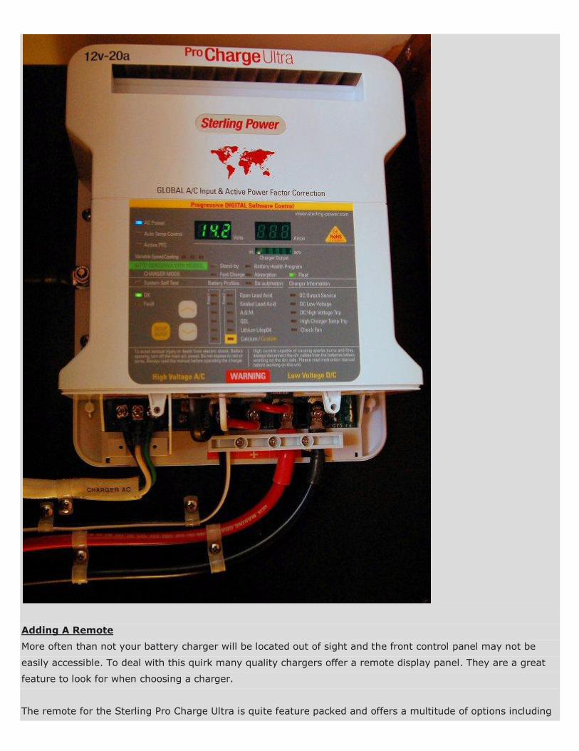
Adding A Remote
More often than not your battery charger will be located out of sight and the front control panel may not be
easily accessible. To deal with this quirk many quality chargers offer a remote display panel. They are a great
feature to look for when choosing a charger.
The remote for the Sterling Pro Charge Ultra is quite feature packed and offers a multitude of options including
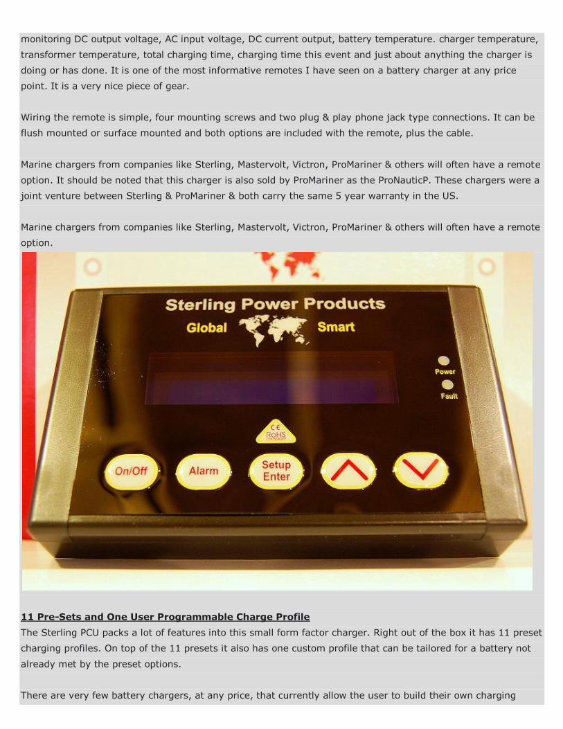
monitoring DC output voltage, AC input voltage, DC current output, battery temperature. charger temperature,
transformer temperature, total charging time, charging time this event and just about anything the charger is
doing or has done. It is one of the most informative remotes I have seen on a battery charger at any price
point. It is a very nice piece of gear.
Wiring the remote is simple, four mounting screws and two plug & play phone jack type connections. It can be
flush mounted or surface mounted and both options are included with the remote, plus the cable.
Marine chargers from companies like Sterling, Mastervolt, Victron, ProMariner & others will often have a remote
option. It should be noted that this charger is also sold by ProMariner as the ProNauticP. These chargers were a
joint venture between Sterling & ProMariner & both carry the same 5 year warranty in the US.
Marine chargers from companies like Sterling, Mastervolt, Victron, ProMariner & others will often have a remote
option.
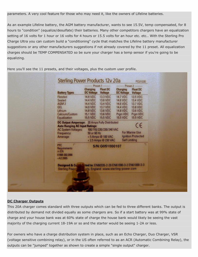
11 Pre-Sets and One User Programmable Charge Profile
The Sterling PCU packs a lot of features into this small form factor charger. Right out of the box it has 11 preset
charging profiles. On top of the 11 presets it also has one custom profile that can be tailored for a battery not
already met by the preset options.
There are very few battery chargers, at any price, that currently allow the user to build their own charging
parameters. A very cool feature for those who may need it, like the owners of Lifeline batteries.
As an example Lifeline battery, the AGM battery manufacturer, wants to see 15.5V, temp compensated, for 8
hours to "condition" (equalize/desulfate) their batteries. Many other competitors chargers have an equalization
setting of 16 volts for 1 hour or 16 volts for 4 hours or 15.5 volts for an hour etc. etc.. With the Sterling Pro
Charge Ultra you can custom build a "conditioning" cycle that matches the Lifeline battery manufacturer
suggestions or any other manufacturers suggestions if not already covered by the 11 preset. All equalization
charges should be TEMP COMPENSATED so be sure your charger has a temp sensor if you're going to be
equalizing.
Here you'll see the 11 presets, and their voltages, plus the custom user profile.
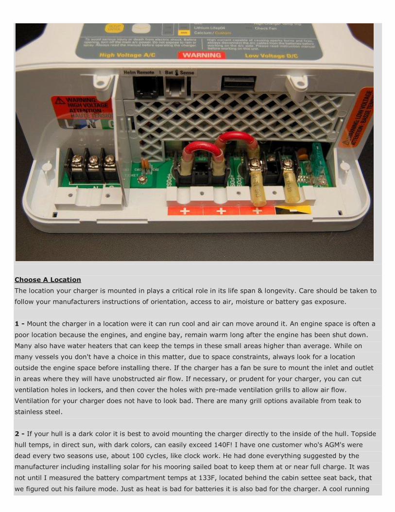
DC Charger Outputs
This 20A charger comes standard with three outputs which can be fed to three different banks. The output is
distributed by demand not divided equally as some chargers are. So if a start battery was at 99% state of
charge and your house bank was at 60% state of charge the house bank would likely be seeing the vast
majority of the charging current 18-19A or so and the starter would be seeing 1-2A or less.
For owners who have a charge distribution system in place, such as an Echo Charger, Duo Charger, VSR
(voltage sensitive combining relay), or in the US often referred to as an ACR (Automatic Combining Relay), the
outputs can be "jumped" together as shown to create a simple "single output" charger.
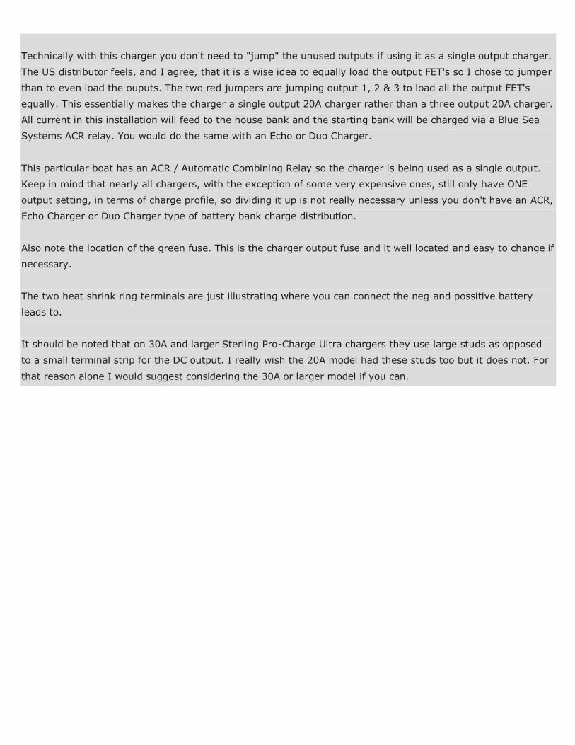
Technically with this charger you don't need to "jump" the unused outputs if using it as a single output charger.
The US distributor feels, and I agree, that it is a wise idea to equally load the output FET's so I chose to jumper
than to even load the ouputs. The two red jumpers are jumping output 1, 2 & 3 to load all the output FET's
equally. This essentially makes the charger a single output 20A charger rather than a three output 20A charger.
All current in this installation will feed to the house bank and the starting bank will be charged via a Blue Sea
Systems ACR relay. You would do the same with an Echo or Duo Charger.
This particular boat has an ACR / Automatic Combining Relay so the charger is being used as a single output.
Keep in mind that nearly all chargers, with the exception of some very expensive ones, still only have ONE
output setting, in terms of charge profile, so dividing it up is not really necessary unless you don't have an ACR,
Echo Charger or Duo Charger type of battery bank charge distribution.
Also note the location of the green fuse. This is the charger output fuse and it well located and easy to change if
necessary.
The two heat shrink ring terminals are just illustrating where you can connect the neg and possitive battery
leads to.
It should be noted that on 30A and larger Sterling Pro-Charge Ultra chargers they use large studs as opposed
to a small terminal strip for the DC output. I really wish the 20A model had these studs too but it does not. For
that reason alone I would suggest considering the 30A or larger model if you can.
Choose A Location
The location your charger is mounted in plays a critical role in its life span & longevity. Care should be taken to
follow your manufacturers instructions of orientation, access to air, moisture or battery gas exposure.
1 - Mount the charger in a location were it can run cool and air can move around it. An engine space is often a
poor location because the engines, and engine bay, remain warm long after the engine has been shut down.
Many also have water heaters that can keep the temps in these small areas higher than average. While on
many vessels you don't have a choice in this matter, due to space constraints, always look for a location
outside the engine space before installing there. If the charger has a fan be sure to mount the inlet and outlet
in areas where they will have unobstructed air flow. If necessary, or prudent for your charger, you can cut
ventilation holes in lockers, and then cover the holes with pre-made ventilation grills to allow air flow.
Ventilation for your charger does not have to look bad. There are many grill options available from teak to
stainless steel.
2 - If your hull is a dark color it is best to avoid mounting the charger directly to the inside of the hull. Topside
hull temps, in direct sun, with dark colors, can easily exceed 140F! I have one customer who's AGM's were
dead every two seasons use, about 100 cycles, like clock work. He had done everything suggested by the
manufacturer including installing solar for his mooring sailed boat to keep them at or near full charge. It was
not until I measured the battery compartment temps at 133F, located behind the cabin settee seat back, that
we figured out his failure mode. Just as heat is bad for batteries it is also bad for the charger. A cool running
charger is a happy charger. If your chargers fan runs constantly it may be trying to tell you something..
3 - Battery chargers should not be mounted in a battery compartment/space despite being ignition protected.
Corrosive battery gas can damage the metals in the charger and lead to shorter life or corrosive damage. All
lead acid batteries, WET, GEL and AGM have the potential to vent corrosive gas. Just because your battery is a
VRLA design does not mean it won't vent corrosive gas if over temped or over charged. A battery compartment
is an absolute last resort location for a charger.
4 - Try to find a location that is dry and will not have the possibility of water dripping on the charger. If there's
even a slight potential of water exposure a drip shield should be constructed to protect the charger. The drip
shield should prevent water from damaging the charger, but also allow for proper cooling. This is not always an
easy task so mounting in a known dry spot is always the best approach. Generally speaking, higher in the boat
is often better than lower in the boat for a charger mounting location. Areas closer to the bilge, or with direct
ambient access to the moist bilge air, tend to be more humid and corrosive environments.
5 - Try to mount the charger as close to the battery bank/banks as possible without mounting in the battery or
engine compartment. Shorter wire runs mean less installation cost, less voltage drop can make for better
charger performance over the long haul.
6 - The area on your vessel where the charger is mounted should be clean and free of oils, vapors or other
sorts of contamination. While UL 1236/ABYC chargers are "ignition protected" it is not recommend to install
them where any gas vapor can accumulate. This includes LPG, gasoline, hydrogen gas or where stored solvents
could spill & leak.
DC WIRING
The DC wiring is a very critical part of a chargers performance. Most manufacturers want to see a max voltage
drop of between 1% & 3%. Voltage drop is determined by the amperage flowing through the cable over the
"round trip" length. This means you add the full length of the negative and positive wires plus the max
amperage that will flow to determine to your voltage drop. This 20A charger was wired up for less than a 1%
voltage drop using 6GA wire. I personally prefer as little drop as possible. Realistically I could have easily wired
this with 10GA wire and been at 2.75% voltage drop but Sterling ideally wants to see less than that and I don't
stock 8GA wire, so 6GA it was..
A 3% voltage drop at 14.6V is roughly 0.44A of lost voltage between the charger and battery bank. This can
potentially leave you with a charging voltage at the battery of just 14.14V. With DC charging sources bigger
wire is almost always better..
I very often use this voltage drop calculator: Voltage Drop Calculator

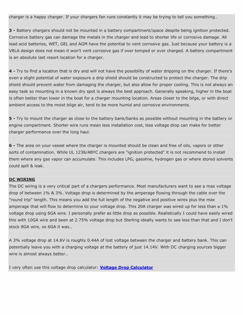
The Temperature Sensor
Temperature sensing of your batteries can be very important to the longevity of a bank especially with valve
regulated lead acid batteries such as AGM/TPPL or GEL. The hotter the climate you are in the more important
temperature compensation is. Temperature compensation is more critical as temperatures rise rather than fall.
As the battery temperature goes up, the battery charging voltage must come down. As battery temperatures
drop the charging voltage can go up.
Heat is one of the number one enemies of batteries. If you have them in an engine room, which is not advised,
you really do need a charger that has temperature compensation to reduce the charging voltage when the
batteries begin to heat up. If your batteries can regularly exceed 80F then you'll ideally want a charger with
temperature compensation. Earlier temp compensation on some chargers was sporadically successful at best,
bordering on "dumb", as in not very smart. With newer technologies they can be accurate to within a degree or
two which is more than enough.
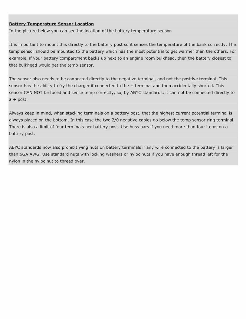
Battery Temperature Sensor Location
In the picture below you can see the location of the battery temperature sensor.
It is important to mount this directly to the battery post so it senses the temperature of the bank correctly. The
temp sensor should be mounted to the battery which has the most potential to get warmer than the others. For
example, if your battery compartment backs up next to an engine room bulkhead, then the battery closest to
that bulkhead would get the temp sensor.
The sensor also needs to be connected directly to the negative terminal, and not the positive terminal. This
sensor has the ability to fry the charger if connected to the + terminal and then accidentally shorted. This
sensor CAN NOT be fused and sense temp correctly, so, by ABYC standards, it can not be connected directly to
a + post.
Always keep in mind, when stacking terminals on a battery post, that the highest current potential terminal is
always placed on the bottom. In this case the two 2/0 negative cables go below the temp sensor ring terminal.
There is also a limit of four terminals per battery post. Use buss bars if you need more than four items on a
battery post.
ABYC standards now also prohibit wing nuts on battery terminals if any wire connected to the battery is larger
than 6GA AWG. Use standard nuts with locking washers or nyloc nuts if you have enough thread left for the
nylon in the nyloc nut to thread over.
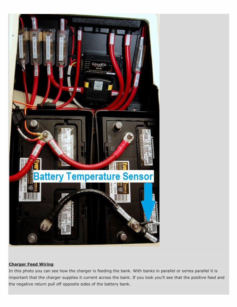
Charger Feed Wiring
In this photo you can see how the charger is feeding the bank. With banks in parallel or series parallel it is
important that the charger supplies it current across the bank. If you look you'll see that the positive feed and
the negative return pull off opposite sides of the battery bank.
Wiring this way forces the current to flow through the entire bank and helps to minimize any intrabank
imbalances. This is one of the most often violated rules of charging I witness on boats. It is important to note
that this is not just for charging sources such as chargers, alternators, wind or solar but also for the DC loads.
Always connect across your bank to keep intrabank imbalances to a minimum. As banks get larger there are
more precise ways of wiring that can lead to better balancing but doing it this was gets you a lot further ahead
than pulling everything off one end.
You will also note the three bussed ANL fuses on the left which protect the ALTERNATOR, HOUSE BANK and
CHARGER wiring. The ABYC requires that any device connected directly to a battery be fused within 7" of the +
battery post to protect the wiring. These fuses are not intended to protect the devices but rather the wiring in
the case of a dead short to ground. While the 7" rule is often very tough to meet always try to get the fuses as
close as you can to the battery + post. The wire marked HOUSE BANK + FEED is about 16" long but runs in a
conduit for about 9", under the quarter berth, then comes out at the fuse.
Because the alternator and charger do not use the same size wiring as the house bank feed to the battery
switch, they each need their own fuse to protect the wire.
When you parallel banks you add or combine the amperage as in Ah's, cranking amps or short circuit
amperage. These group 31 wet cell batteries can pump out in excess of 1200 cranking amps at 70F. For just
two of these batteries that is 2400+ amps of cranking current at 70F. The short circuit current is always slightly
higher than CA at 70F. Marine Cranking Amps (MCA) are rated at 32F and Cold Cranking Amps (CCA) are rated
at 0F. As temps drop you have less available cranking amps and as the temp climbs the more amps you have
to fry things. 2400 amps is enough to weld metal with and that is not even the short circuit rating!
I have one customer with 4 Odyssey thin plate pure lead (TPPL) batteries w/ over 20,000 short circuit amps as
a bank. If you short this bank the insulation will catch fire in mere seconds. Always fuse devices connected
directly to the battery and fuse it for the WIRES ampacity rating.
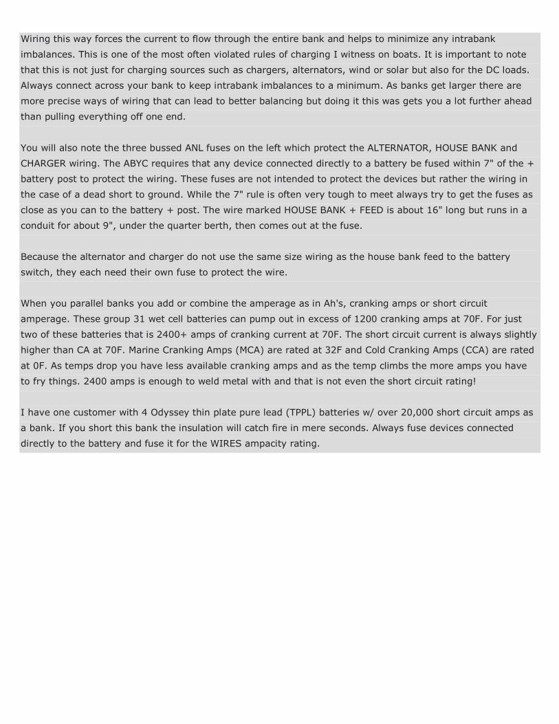
Fuse Distribution Close-Up
This is the fuse distribution buss I talked about in the last photo. The three ANL fuses are bussed together with
copper bar stock at the top of the fuses. The source wire from the house bank comes in the top and the
ALTERNATOR, BATTERY SWITCH FEED, CHARGER/ACR are protected out the bottom.
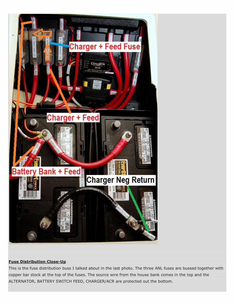
There are many ways to fuse devices and banks like this. For this application I found the bussed ANL fuses a
good fit.
The inverter fuse on the right is controlled via the battery switch and as such it was not "bussed" with the
alternator, battery switch and charger/ACR.....
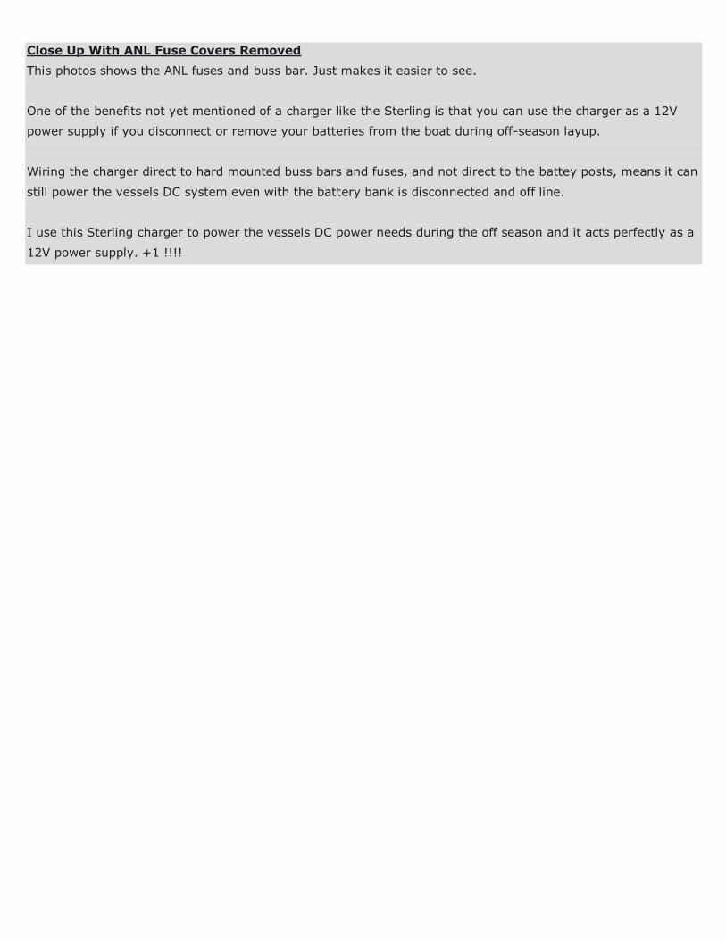
Close Up With ANL Fuse Covers Removed
This photos shows the ANL fuses and buss bar. Just makes it easier to see.
One of the benefits not yet mentioned of a charger like the Sterling is that you can use the charger as a 12V
power supply if you disconnect or remove your batteries from the boat during off-season layup.
Wiring the charger direct to hard mounted buss bars and fuses, and not direct to the battey posts, means it can
still power the vessels DC system even with the battery bank is disconnected and off line.
I use this Sterling charger to power the vessels DC power needs during the off season and it acts perfectly as a
12V power supply. +1 !!!!

Parallel Batteries - Correct Hook Up
This illustration will better show how to connect charger sources and loads. Connect "across" the bank and it
will force the batteries to charge & discharge more evenly and uniformly. This is the recommended diagram by
every battery manufacturer I know of from Trojan, Lifeline, Deka/East Penn to Rolls Battery and just about
everyone in-between.
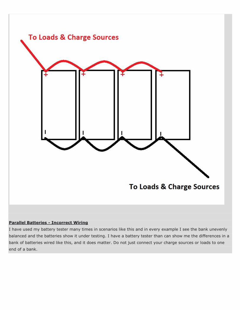
Parallel Batteries - Incorrect Wiring
I have used my battery tester many times in scenarios like this and in every example I see the bank unevenly
balanced and the batteries show it under testing. I have a battery tester than can show me the differences in a
bank of batteries wired like this, and it does matter. Do not just connect your charge sources or loads to one
end of a bank.
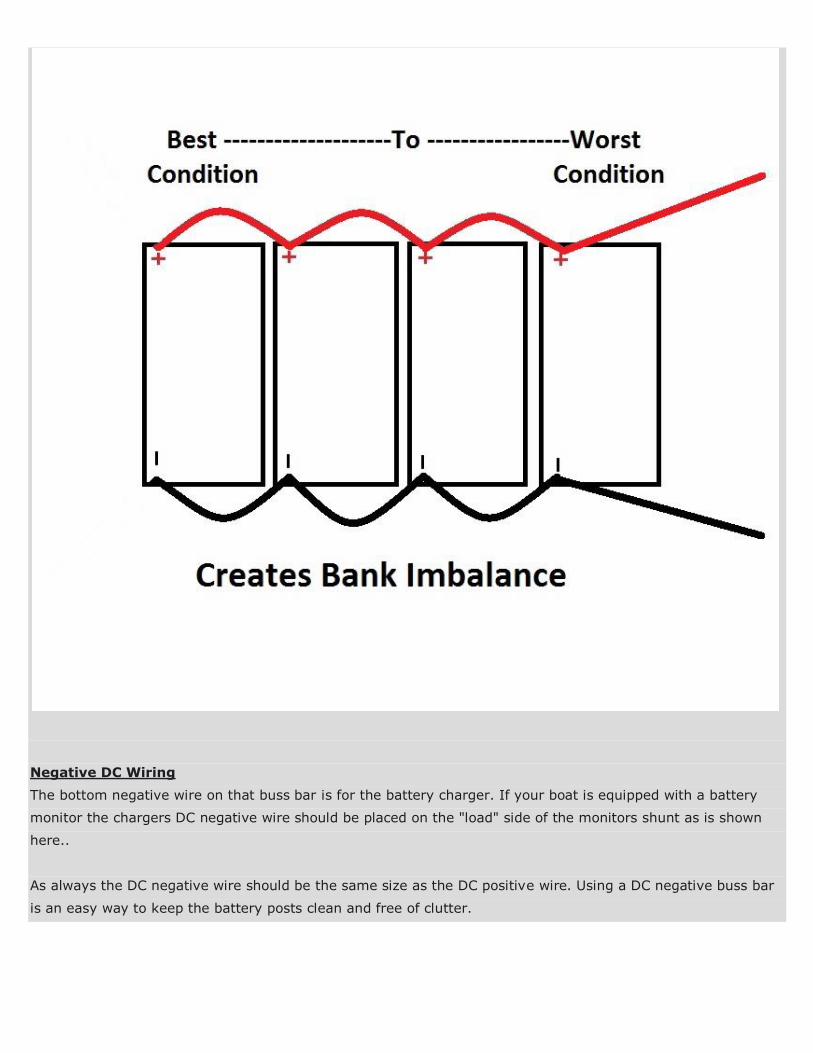
Negative DC Wiring
The bottom negative wire on that buss bar is for the battery charger. If your boat is equipped with a battery
monitor the chargers DC negative wire should be placed on the "load" side of the monitors shunt as is shown
here..
As always the DC negative wire should be the same size as the DC positive wire. Using a DC negative buss bar
is an easy way to keep the battery posts clean and free of clutter.
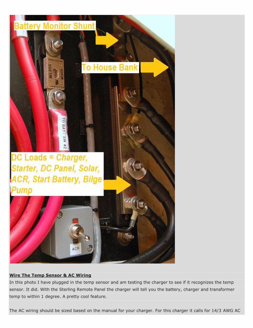
Wire The Temp Sensor & AC Wiring
In this photo I have plugged in the temp sensor and am testing the charger to see if it recognizes the temp
sensor. It did. With the Sterling Remote Panel the charger will tell you the battery, charger and transformer
temp to within 1 degree. A pretty cool feature.
The AC wiring should be sized based on the manual for your charger. For this charger it calls for 14/3 AWG AC
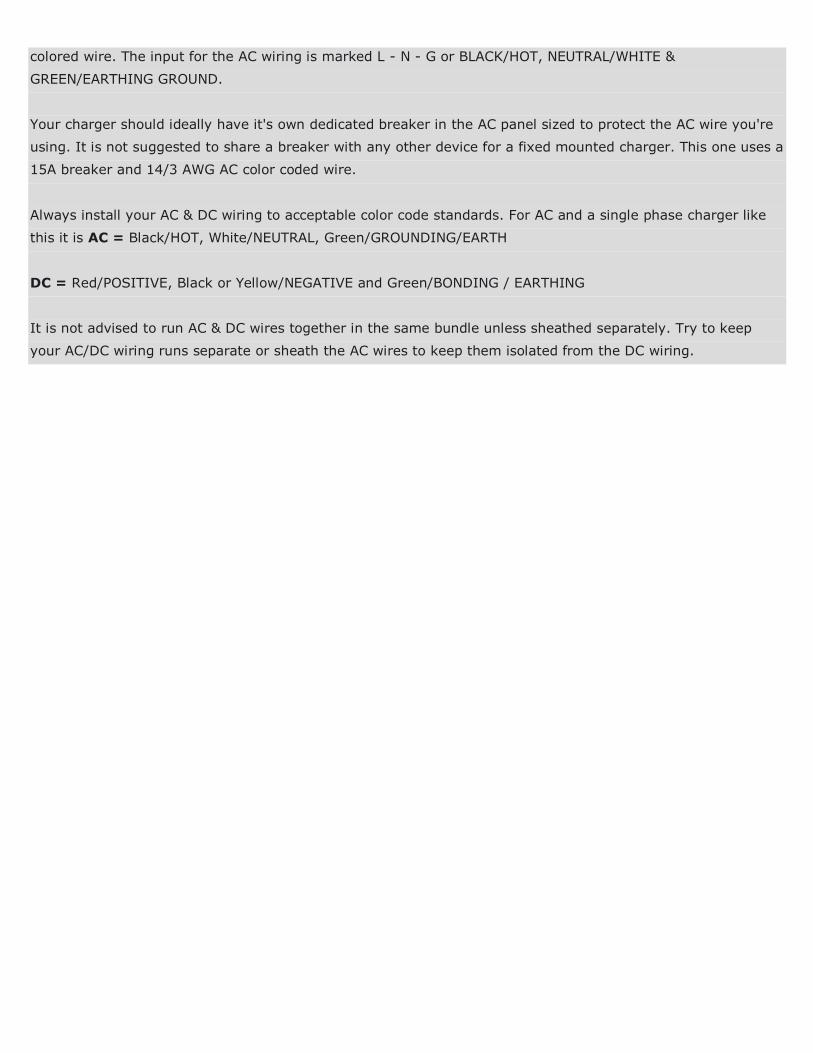
colored wire. The input for the AC wiring is marked L - N - G or BLACK/HOT, NEUTRAL/WHITE &
GREEN/EARTHING GROUND.
Your charger should ideally have it's own dedicated breaker in the AC panel sized to protect the AC wire you're
using. It is not suggested to share a breaker with any other device for a fixed mounted charger. This one uses a
15A breaker and 14/3 AWG AC color coded wire.
Always install your AC & DC wiring to acceptable color code standards. For AC and a single phase charger like
this it is AC = Black/HOT, White/NEUTRAL, Green/GROUNDING/EARTH
DC = Red/POSITIVE, Black or Yellow/NEGATIVE and Green/BONDING / EARTHING
It is not advised to run AC & DC wires together in the same bundle unless sheathed separately. Try to keep
your AC/DC wiring runs separate or sheath the AC wires to keep them isolated from the DC wiring.
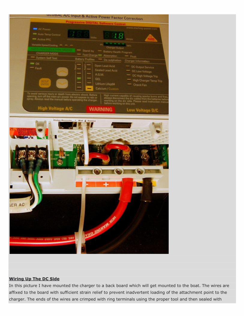
Wiring Up The DC Side
In this picture I have mounted the charger to a back board which will get mounted to the boat. The wires are
affixed to the board with sufficient strain relief to prevent inadvertent loading of the attachment point to the
charger. The ends of the wires are crimped with ring terminals using the proper tool and then sealed with
adhesive lined heat shrink. I also coat the lugs with a terminal grease to prevent oxidation/corrosion at the
lug/terminal strip interface.
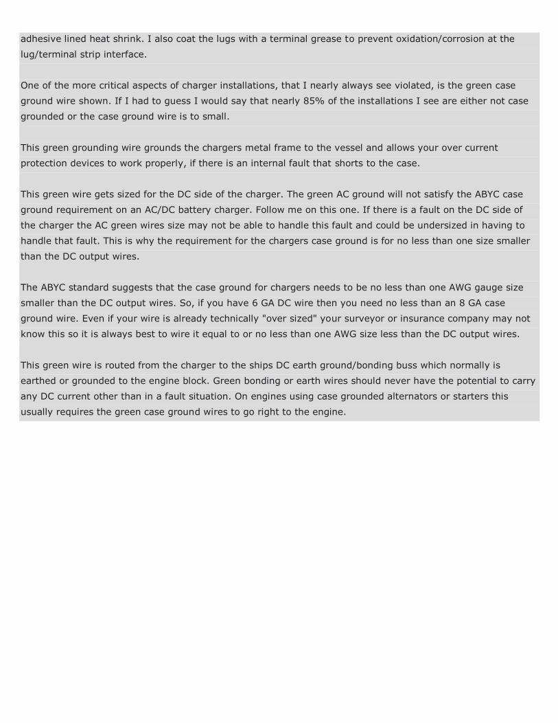
One of the more critical aspects of charger installations, that I nearly always see violated, is the green case
ground wire shown. If I had to guess I would say that nearly 85% of the installations I see are either not case
grounded or the case ground wire is to small.
This green grounding wire grounds the chargers metal frame to the vessel and allows your over current
protection devices to work properly, if there is an internal fault that shorts to the case.
This green wire gets sized for the DC side of the charger. The green AC ground will not satisfy the ABYC case
ground requirement on an AC/DC battery charger. Follow me on this one. If there is a fault on the DC side of
the charger the AC green wires size may not be able to handle this fault and could be undersized in having to
handle that fault. This is why the requirement for the chargers case ground is for no less than one size smaller
than the DC output wires.
The ABYC standard suggests that the case ground for chargers needs to be no less than one AWG gauge size
smaller than the DC output wires. So, if you have 6 GA DC wire then you need no less than an 8 GA case
ground wire. Even if your wire is already technically "over sized" your surveyor or insurance company may not
know this so it is always best to wire it equal to or no less than one AWG size less than the DC output wires.
This green wire is routed from the charger to the ships DC earth ground/bonding buss which normally is
earthed or grounded to the engine block. Green bonding or earth wires should never have the potential to carry
any DC current other than in a fault situation. On engines using case grounded alternators or starters this
usually requires the green case ground wires to go right to the engine.
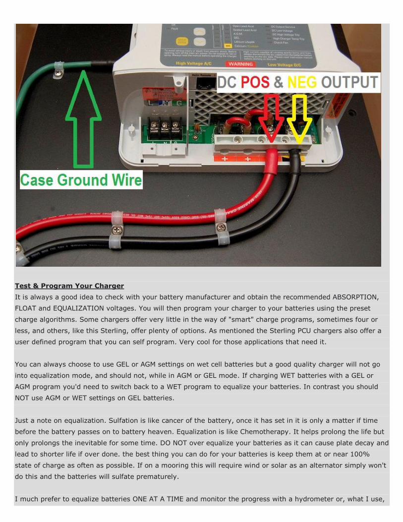
Test & Program Your Charger
It is always a good idea to check with your battery manufacturer and obtain the recommended ABSORPTION,
FLOAT and EQUALIZATION voltages. You will then program your charger to your batteries using the preset
charge algorithms. Some chargers offer very little in the way of "smart" charge programs, sometimes four or
less, and others, like this Sterling, offer plenty of options. As mentioned the Sterling PCU chargers also offer a
user defined program that you can self program. Very cool for those applications that need it.
You can always choose to use GEL or AGM settings on wet cell batteries but a good quality charger will not go
into equalization mode, and should not, while in AGM or GEL mode. If charging WET batteries with a GEL or
AGM program you'd need to switch back to a WET program to equalize your batteries. In contrast you should
NOT use AGM or WET settings on GEL batteries.
Just a note on equalization. Sulfation is like cancer of the battery, once it has set in it is only a matter if time
before the battery passes on to battery heaven. Equalization is like Chemotherapy. It helps prolong the life but
only prolongs the inevitable for some time. DO NOT over equalize your batteries as it can cause plate decay and
lead to shorter life if over done. the best thing you can do for your batteries is keep them at or near 100%
state of charge as often as possible. If on a mooring this will require wind or solar as an alternator simply won't
do this and the batteries will sulfate prematurely.
I much prefer to equalize batteries ONE AT A TIME and monitor the progress with a hydrometer or, what I use,
a sight refractometer. A good charger with temp sensor should monitor the temp but it never hurts to have a
digital infrared thermometer on hand while equalizing. Please DO NOT equalize batteries unattended! It is very
wise to be there during equalization. If you are unfamiliar with equalization PLEASE research this before hitting
the button. To equalize one at a time simply disconnect the batteries not being equalized.
Thoroughly test your charger before leaving it to do it's thing. I personally don't like "unattended" charging
even with the best built chargers in the world. This is just MY personal preference, so consider it, but don't take
it as gospel. For unattended charging I use solar. It works for us, but may not for you.
Unfortunately for many boaters in warmer climates, with WET cell batteries, the ambient temps require that
chargers be left on and most often "unattended". This is due to the exacerbation of battery self discharge in
warmer temperatures. Heat kills batteries, cold helps prolong life.
Sulfation and self discharge greatly accelerate the warmer battery temps are, so do keep your batteries topped
up as often as you can. In a perfect world all chargers would perform flawlessly for 20+ years. Sadly for the
boating public we don't live in a perfect world and many a charger has taken out a perfectly good bank when it
decided to pack it in, I see it OFTEN. When owners leave a charger on constantly when the charger fails it often
takes the batteries out with it. This simple charger failure now becomes an entire new bank and a new charger
as opposed to just a charger. If you don't need your charger on constantly consider NOT leaving it on and
unattended, if you don't absolutely need to. Balancing unattended charging & its potentials for failure modes,
versus the potential for self discharge and the resulting sulfation is one you'll have to tackle on your own.
Good luck with your installation!!
Marine Battery Chargers - Installation Tips & Considerations This article written by: RC Collins of
Compass Marine Inc. Images in this .pdf copyright of Compass Marine Service
Good luck with your installation!!
Marine Battery Chargers - Installation Tips & Considerations This article written by: RC Collins of
Compass Marine Inc. Images in this .pdf copyright of Compass Marine Service