bacnet integration manual itg-vt7600-bac-e01 · 2012-02-22 · bacnet integration manual...
TRANSCRIPT

1
VT7600 Series Programmable & Non-Programmable Thermostats
For Commercial HVAC Applications
BACnet Integration Manual ITG-VT7600-BAC-E01

2
Product Overview
The VT7600 PI thermostat family is specifically designed for single stage and multi-stage control of heating/cooling equipment such as rooftop and self-contained units. The product features an intuitive, menu-driven, backlit LCD display that walks users through the programming steps, making the process extremely simple. Accurate temperature control is achieved due to the product’s PI time proportional control algorithm, which virtually eliminates temperature offset associated with traditional, differential-based thermostats.
All models contain two digital inputs, which can be set by the user to monitor filter status, activate a remote temporary occupancy switch, and/or used as a general purpose service indicator. In addition, depending on the model, up to three remote sensors inputs are available. All programmable models contain a SPST auxiliary switch, which can be used to control lighting or disable the economizer function. For more advanced applications, an economizer control logic has been integrated onto the thermostat for use with proportional damper economizer actuators.
The additional following documentation is available on www.Lynxspring.com • Detailed information on the thermostat (VT76xxX1020), is available on document LIT-VT7600-E01. Contents
Subject Page VT7600 series Protocol Implementation Conformance Statements (PICS) 3
Objects Table 4 Standard Object Types Supported 8 List of Proprietary Properties 8 List of Property Value Range 9 List of Property Enumeration Set for BIs and BVs 9 List of Property Enumeration Set for MVs 10 Integration - Global commands 12 Integration - Graphic User Interface (GUI) Objects 13 Integration - Configuration objects 14 Wiring Guide 14
Overview 14 Network Configuration 15 Maximum number of devices 16 Maximum cable length 16 EI-485 Repeaters 17 End Of Line Resistors 18
Network Adapter 18 Default Device Name and Device ID 19 Tips And thing You Need To Know 19 Troubleshooting Section 20 Document Control 20
3
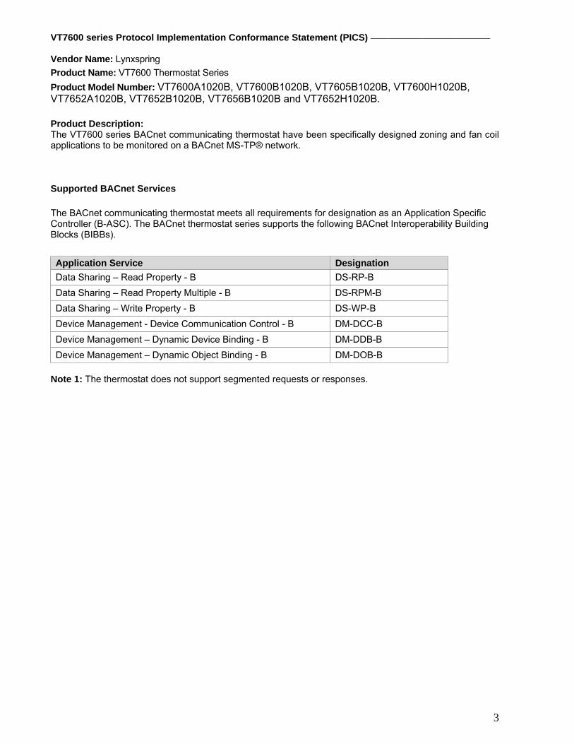
VT7600 series Protocol Implementation Conformance Statement (PICS) Vendor Name: Lynxspring Product Name: VT7600 Thermostat Series Product Model Number: VT7600A1020B, VT7600B1020B, VT7605B1020B, VT7600H1020B, VT7652A1020B, VT7652B1020B, VT7656B1020B and VT7652H1020B. Product Description: The VT7600 series BACnet communicating thermostat have been specifically designed zoning and fan coil applications to be monitored on a BACnet MS-TP® network. Supported BACnet Services
The BACnet communicating thermostat meets all requirements for designation as an Application Specific Controller (B-ASC). The BACnet thermostat series supports the following BACnet Interoperability Building Blocks (BIBBs). Application Service Designation Data Sharing – Read Property - B DS-RP-B Data Sharing – Read Property Multiple - B DS-RPM-B Data Sharing – Write Property - B DS-WP-B Device Management - Device Communication Control - B DM-DCC-B Device Management – Dynamic Device Binding - B DM-DDB-B Device Management – Dynamic Object Binding - B DM-DOB-B
Note 1: The thermostat does not support segmented requests or responses.

4
Objects Table
Object Name Type and Instance Object Property Thermostat Parameter
VT7600xYYYYB Device 76004
Object_Identifier (R,W) Unique ID number of a device on a network
Object_Name (R,W) Unique name of a Device on a network
Max_Master (R,W) Maximum master devices allowed to be part of the network
Major_Version (R) N/A
MS/TP_Address (R,W) BACnet Address
MS/TP_Baud_Rate (R,W) N/A
Object Name Type and Instance Object Property
VT76
00A
1020
B
VT76
00B
1020
B
VT76
05B
1020
B
VT76
00H
1020
B
VT76
52A
1020
B
VT76
52B
1020
B
VT76
56B
1020
B
VT76
52H
1020
B
Room Temperature AV 7 Present_Value (R,W) √ √ √ √ √ √ √ √
Room Temp Override BV 8 Present_Value (R,W) √ √ √ √ √ √ √ √
Outdoor Temperature AV 9 Present_Value (R,W) √ √ √ √ √ √ √ √
Outdoor Temp Override BV 10 Present_Value (R,W) √ √ √ √ √ √ √ √
Occupancy MV 11 Present_Value (R,W) √ √ √ √ √ √ √ √ System Mode HPU MV 12 Present_Value (R,W) √ √
System Mode RTU MV 13 Present_Value (R,W) √ √ √ √ √ √
Fan Mode MV 14 Present_Value (R,W) √ √ √ √ √ √ √ √ Supply Temperature AI 15 Present_Value (R) √ √ √ √ √ √ √ √
Keypad Lockout MV 16 Present_Value (R,W) √ √ √ √ √ √ √ √ Present_Value (R,W) √ √ √ √
Occupancy Status
Monday
Tuesday
Wednesday
Thursday
Friday
Saturday
Schedule SCH 78
Weekly_Schedule (R,W)
Sunday The Weekly_Schedule property will contain all the schedules for the week.
5
Object Name
Type and Instance Object Property
VT76
00A
1020
B
VT76
00B
1020
B
VT76
05B
1020
B
VT76
00H
1020
B
VT76
52A
1020
B
VT76
52B
1020
B
VT76
56B
1020
B
VT76
52H
1020
B
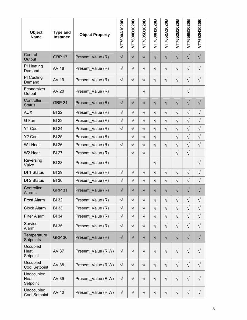
Control Output GRP 17 Present_Value (R) √ √ √ √ √ √ √ √
PI Heating Demand AV 18 Present_Value (R) √ √ √ √ √ √ √ √
PI Cooling Demand AV 19 Present_Value (R) √ √ √ √ √ √ √ √
Economizer Output AV 20 Present_Value (R) √ √
Controller Status GRP 21 Present_Value (R) √ √ √ √ √ √ √ √
AUX BI 22 Present_Value (R) √ √ √ √ √ √ √ √ G Fan BI 23 Present_Value (R) √ √ √ √ √ √ √ √ Y1 Cool BI 24 Present_Value (R) √ √ √ √ √ √ √ √ Y2 Cool BI 25 Present_Value (R) √ √ √ √ √ √ W1 Heat BI 26 Present_Value (R) √ √ √ √ √ √ √ √ W2 Heat BI 27 Present_Value (R) √ √ √ √
Reversing Valve BI 28 Present_Value (R) √ √
DI 1 Status BI 29 Present_Value (R) √ √ √ √ √ √ √ √ DI 2 Status BI 30 Present_Value (R) √ √ √ √ √ √ √ √ Controller Alarms GRP 31 Present_Value (R) √ √ √ √ √ √ √ √
Frost Alarm BI 32 Present_Value (R) √ √ √ √ √ √ √ √ Clock Alarm BI 33 Present_Value (R) √ √ √ √ √ √ √ √ Filter Alarm BI 34 Present_Value (R) √ √ √ √ √ √ √ √ Service Alarm BI 35 Present_Value (R) √ √ √ √ √ √ √ √
Temperature Setpoints GRP 36 Present_Value (R) √ √ √ √ √ √ √ √
Occupied Heat Setpoint
AV 37 Present_Value (R,W) √ √ √ √ √ √ √ √
Occupied Cool Setpoint AV 38 Present_Value (R,W) √ √ √ √ √ √ √ √
Unoccupied Heat Setpoint
AV 39 Present_Value (R,W) √ √ √ √ √ √ √ √
Unoccupied Cool Setpoint AV 40 Present_Value (R,W) √ √ √ √ √ √ √ √

6
Object Name
Type and Instance Object Property
VT76
00A
1020
B
VT76
00B
1020
B
VT76
05B
1020
B
VT76
00H
1020
B
VT76
52A
1020
B
VT76
52B
1020
B
VT76
56B
1020
B
VT76
52H
1020
B
General Options 1 GRP 41 Present_Value (R) √ √ √ √ √ √ √ √
Temperature Scale BV 42 Present_Value (R,W) √ √ √ √ √ √ √ √
Heating Setpoint Limit
AV 43 Present_Value (R,W) √ √ √ √ √ √ √ √
Cooling Setpoint Limit
AV 44 Present_Value (R,W) √ √ √ √ √ √ √ √
Heating Lockout Temperature
AV 45 Present_Value (R,W) √ √ √ √ √ √ √ √
Cooling Lockout Temperature
AV 46 Present_Value (R,W) √ √ √ √ √ √ √ √
Deadband AV 47 Present_Value (R,W) √ √ √ √ √ √ √ √ Heating CPH MV 48 Present_Value (R,W) √ √ √ √ √ √ √ √ Cooling CPH MV 49 Present_Value (R,W) √ √ √ √ √ √ √ √ Frost Protection BV 50 Present_Value (R,W) √ √ √ √ √ √ √ √
General Options 2 GRP 51 Present_Value (R) √ √ √ √ √ √ √ √
Power-up Delay AV 52 Present_Value (R,W) √ √ √ √ √ √ √ √
Temporary Occupancy Time
MV 53 Present_Value (R,W) √ √ √ √ √ √ √ √
Fan Control BV 54 Present_Value (R,W) √ √ √ √ √ √ √ √ Min. On/Off Time MV 55 Present_Value (R,W) √ √ √ √ √ √ √ √
Fan Purge Delay BV 56 Present_Value (R,W) √ √ √ √ √ √ √ √
DI 1 Configuration MV 57 Present_Value (R,W) √ √ √ √ √ √ √ √
DI 2 Configuration MV 58 Present_Value (R,W) √ √ √ √ √ √ √ √

7
Object Name Type and Instance Object Property
VT76
00A
1020
B
VT76
00B
1020
B
VT76
05B
1020
B
VT76
00H
1020
B
VT76
52A
1020
B
VT76
52B
1020
B
VT76
56B
1020
B
VT76
52H
1020
B
Program Options GRP 59 Present_Value (R) √ √ √ √ √ √ √ √
Aux Contact BV 60 Present_Value (R,W) √ √ √ √ √ √ √ √ Progressive Recovery BV 61 Present_Value (R,W) √ √ √ √
Event Display MV 62 Present_Value (R,W) √ √ √ √ Stages GRP 63 Present_Value (R) √ √ √ √ √ √
Heating Stages MV 64 Present_Value (R,W) √ √ √ √
Cooling Stages MV 65 Present_Value (R,W) √ √ √ √
Heat Pump Stages MV 66 Present_Value (R,W) √ √
Economizer GRP 67 Present_Value (R) √ √
Economizer Changeover Setpoint
AV 68 Present_Value (R,W) √ √
Economizer Minimum Position
AV 69 Present_Value (R,W) √ √
Mechanical Cooling BV 70 Present_Value (R,W) √ √
Mixed Air Setpoint AV 71 Present_Value (R,W) √ √
Heat Pump GRP 72 Present_Value (R) √ √
High Balance Point AV 73 Present_Value (R,W) √ √
Low Balance Point AV 74 Present_Value (R,W) √ √
Comfort Mode BV 75 Present_Value (R,W) √ √
Reversing Valve Configuration
BV 76 Present_Value (R,W) √ √
Compressor Interlock BV 77 Present_Value (R,W) √ √

8
Standard Object Types Supported
Object Type Supported Objects
Dynamically Creatable
Dynamically Deletable
Optional Properties Supported
Writable Properties
Analog Input Reliability Out_of_Service
Analog Value Reliability Present_Valuea Out_of_Servicea Object_Nameb
Binary Input Reliability
Active_Text Inactive_Text
Out_of_Service
Binary Value Reliability
Active_Text Inactive_Text
Present_Value Out_of_Service
Device Max_Master Max_Info_frames
Object_Identifier Object_name Max_Master
Group N/A N/A
Multi-state Value Reliability States_Text
Present_Value Out_of_Service
Schedule Weekly_schedule Present_Value Weekly_Schedule
a: Present_Value and Out_of_Service properties are writable for every AV objects except :
PI Heating Demand (AV18) PI Cooling Demand (AV19) Economizer Output (AV20)
b: Object_Name property is writable for 2 objects only : Room_Temperature (AV6) Outdoor_Temperature (AV8)
List of proprietary properties
Property name ID BACnet Data type Description
Major_Version 1000 CharacterString The version number of the BACnet communications module. This the hardware version number
MS/TP_Address 1001 Unsigned Display the MAC layer address of the module
MS/TP_Baud_Rate 1002 Unsigned Display the communication baud rate of the module
Sensor_Offset 1005 REAL Display the temperature or humidity calibration value. The range is –5.0 deg F to 5.0 deg F for a temperature and –15% to 15% for humidity.

9
List of property value range restrictions
Object name Object Type and instance
Under range value
Over range value Default value
Supply Temperature AI15 -40°F (-40°C) 122°F (50°C) N/A Room Temperature AV7 -40°F (-40°C) 122°F (50°C) N/A Outdoor Temperature AV9 -40°F (-40°C) 122°F (50°C) N/A PI Heating demand AV18 0% 100% 0% PI Cooling demand AV19 0% 100% 0% Economizer Output AV20 0% 100% 0% Occupied Heat Setpoint AV37 40°F (4.5°C) 90°F (32°C) 72°F (22°C) Occupied Cool Setpoint AV38 54°F (12°C) 100°F (37.5°C) 75°F (24°C) Unoccupied Heat Setpoint AV39 40°F (4.5°C) 90°F (32°C) 62°F (16.5°C) Unoccupied Cool Setpoint AV40 54°F (12°C) 100°F (37.5) 80°F (26.5°C) Heating Setpoint Limit AV43 40°F (4.5°C) 90°F (32°C) 90°F (32°C) Cooling Setpoint Limit AV44 54°F (12°C) 100°F (37.5) 54°F (12°C) Heating Lockout Temperature AV45 -15°F (-26°C) 120°F (49°C) 120°F (49°C) Cooling Lockout Temperature AV46 -40°F (-40°C) 95°F (35°C) -40°F (-40°C) Deadband AV47 2°F (1°C) 5°F (2.5°C) 2°F (1°C) Power-Up Delay AV52 10 sec 120 sec 10 sec Economizer Changeover Setpoint AV68 14°F (-10°C) 70°F (21°C) 55°F (13°C) Economizer Minimum Position AV69 0% 100% 0% Mixed Air Setpoint AV71 50°F (10°C) 90°F (32°C) 55°F (13°C) High Balance Point AV73 34°F (1°C) 90°F (32°C) 90°F (32°C) Low Balance Point AV74 -40°F (-40°C) 30°F (-1°C) -12°F (-24°C)
List of property enumeration sets for BV objects and BI objects
Object Name Object Type and instance Inactive_Text Active_Text Default
value Room Temp Override BV8 Normal Override Normal Outdoor Temp Override BV10 Normal Override Normal Aux BI22 Off On Off G Fan BI23 Off On Off Y1 Cool BI24 Off On Off Y2 Cool BI25 Off On Off W1 Heat BI26 Off On Off W2 Heat BI27 Off On Off Reversing Valve BI28 Off On Off DI 1 Status BI29 Activated Not Activated Not Activated DI 2 Status BI30 Activated Not Activated Not Activated Frost Alarm BI32 Off On Off Clock Alarm BI33 Off On Off Filter Alarm BI34 Off On Off Service Alarm BI35 Off On Off Temperature Scale BV42 C F °F Frost Protection BV50 Off On Off Fan Control BV54 Off On On Fan Purge Delay BV56 Off On Off Aux Contact BV60 N.O. N.C. N.O. Progressive Recovery BV61 Off Active Off Mechanical Cooling BV70 Off On Off Comfort Mode BV75 Comfort Economy Comfort Reversing Valve Configuration BV76 Normally Heat Normally
Cool Normally Cool
Compressor Interlock BV77 Off On Off

10
List of property enumeration sets for MV objects
Object Name Object
Type and instance
BACnet Index Text Default value
1 Resume Schedule 2 Occupied 3 Unoccupied
Occupancy MV11
4 Temporary Occupied
Resume Schedule
1 Off 2 Auto 3 Cool 4 Heat
System Mode HPU MV12
5 Emergency
Auto
1 Off 2 Auto 3 Cool
System Mode RTU MV13
4 Heat
Auto
1 On 2 Auto Fan Mode MV14 3 Smart
Auto
1 Level 0 2 Level 1 Keypad Lockout MV16 3 Level 2
Level 0
1 3 CPH 2 4 CPH 3 5 CPH 4 6 CPH 5 7 CPH
Heating CPH MV48
6 8 CPH
4 CPH
1 3 CPH Cooling CPH MV49
2 4 CPH 4 CPH
1 0 hour 2 1 hour 3 2 hours 4 3 hours 5 4 hours 6 5 hours 7 6 hours 8 7 hours 9 8 hours 10 9 hours 11 10 hours 12 11 hours
Temporary Occupancy Time MV53
13 12 hours
3 hours
1 0 minute 2 1 minute 3 2 minutes 4 3 minutes 5 4 minutes
Minimum On/Off Time MV55
6 5 minutes
2 minutes

11
Object Name Object
Type and instance
BACnet Index Text Default value
1 None 2 Rem NSB 3 Override 4 Filter
DI1 Configuration MV57
5 Service
None
1 None 2 Rem NSB 3 Override 4 Filter
DI2 Configuration MV58
5 Service
None
1 2 Events Event Display MV62
2 4 Events 2 Event
1 1 Stage Heating Stages MV64
2 2 Stages 2 Stages
1 1 Stage Cooling Stages MV65
2 2 Stages 2 Stages
1 1 Stage Heat Pump Stages MV66
2 2 Stages 2 Stages

12
Integration – Global Commands The following figure shows which objects from the thermostat can be monitored and commanded from the
Global Command Control Level Device Level
Figure 1: Global commands from a BAS front-end to a VT7600 series thermostat
MSTP Network
BAS front-end VT7600 series tstat
Outdoor Temperature Outdoor Temperature (AV9)
Schedule Occupancy (MV11)
BAS current energy savings mode
Schedule and Outdoor Temperature
Fan Mode (MV14)
Occupied Heating Setpoint (AV37)Unoccupied Heating Setpoint (AV39)Occupied Cooling Setpoint (AV38)Unoccupied Cooling Setpoint (AV40)
Restrict user access to thermostat Keypad Lockout (MV16)
Outdoor Temperature and HVAC plant current mode System Mode (MV13)
Global commands all devices( All thermostats )
Global commands specific devices( Specific area thermostats )
Room Temperaturefor testing and override Room Temperature (AV7)

13
Integration – Graphic User Interface (GUI) objects The following objects should be typically used in a GUI:
Room Temperature (AV7); Occupied and Unoccupied Heat Setpoints (AV 37 and AV39); Occupied and Unoccupied Cool Setpoints (AV 38 and AV40); Outdoor Temperature (AV9); Supply Temperature (AI15) (If available); Occupancy (MV11); System Mode RTU (MV13) or System Mode HPU (MV12); G Fan (BI23); Y1 Cool (BI24); Y2 Cool (BI25); W1 Heat (BI26); W2 Heat (BI27) or Reversing Valve (BI28); Economizer Output (AV20) (if available); Aux (BI22); DI 1 Status (BI 29); DI 2 Status (BI 30); Frost Alarm (BI32) (if available); Filter Alarm (BI34) (if available); Service Alarm (BI 35) (if available);
14
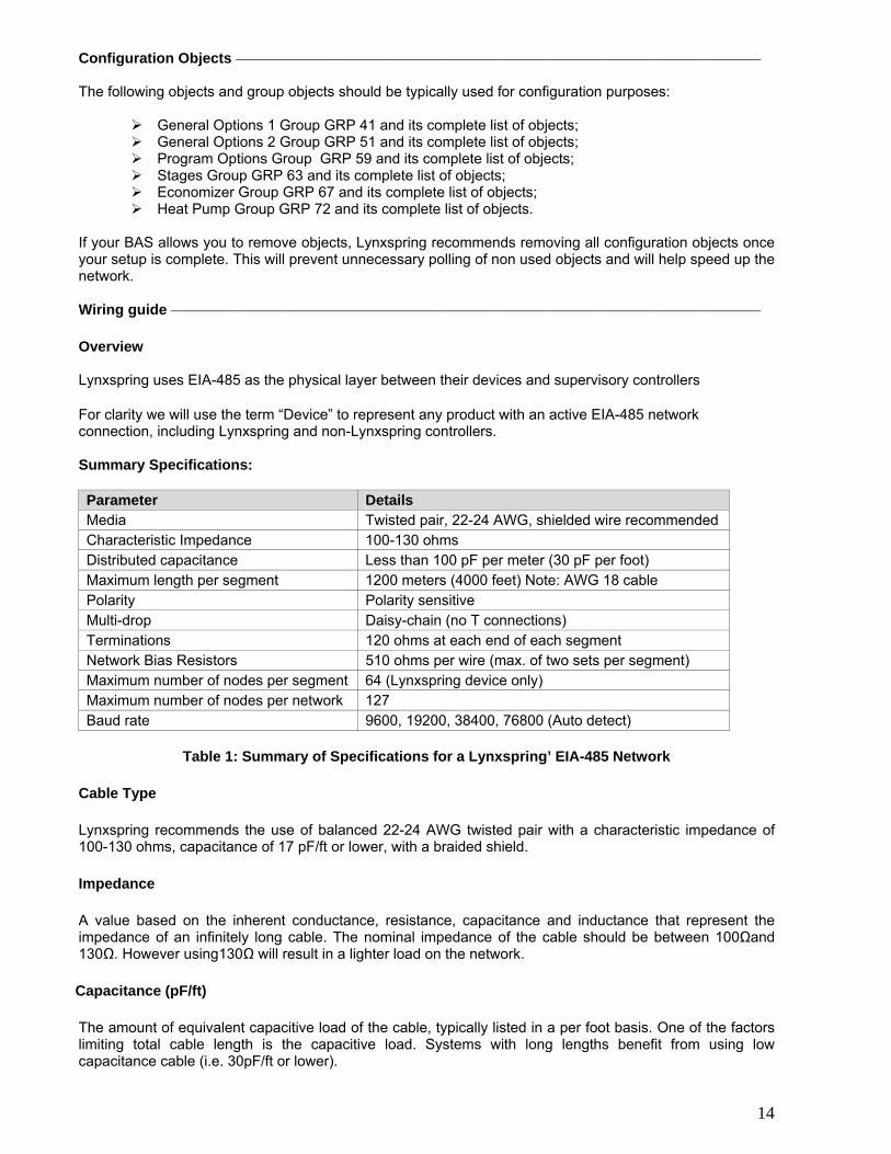
Configuration Objects The following objects and group objects should be typically used for configuration purposes:
General Options 1 Group GRP 41 and its complete list of objects; General Options 2 Group GRP 51 and its complete list of objects; Program Options Group GRP 59 and its complete list of objects; Stages Group GRP 63 and its complete list of objects; Economizer Group GRP 67 and its complete list of objects; Heat Pump Group GRP 72 and its complete list of objects.
If your BAS allows you to remove objects, Lynxspring recommends removing all configuration objects once your setup is complete. This will prevent unnecessary polling of non used objects and will help speed up the network. Wiring guide Overview Lynxspring uses EIA-485 as the physical layer between their devices and supervisory controllers
For clarity we will use the term “Device” to represent any product with an active EIA-485 network connection, including Lynxspring and non-Lynxspring controllers. Summary Specifications: Parameter Details Media Twisted pair, 22-24 AWG, shielded wire recommended Characteristic Impedance 100-130 ohms Distributed capacitance Less than 100 pF per meter (30 pF per foot) Maximum length per segment 1200 meters (4000 feet) Note: AWG 18 cable Polarity Polarity sensitive Multi-drop Daisy-chain (no T connections) Terminations 120 ohms at each end of each segment Network Bias Resistors 510 ohms per wire (max. of two sets per segment) Maximum number of nodes per segment 64 (Lynxspring device only) Maximum number of nodes per network 127 Baud rate 9600, 19200, 38400, 76800 (Auto detect)
Table 1: Summary of Specifications for a Lynxspring’ EIA-485 Network Cable Type Lynxspring recommends the use of balanced 22-24 AWG twisted pair with a characteristic impedance of 100-130 ohms, capacitance of 17 pF/ft or lower, with a braided shield. Impedance A value based on the inherent conductance, resistance, capacitance and inductance that represent the impedance of an infinitely long cable. The nominal impedance of the cable should be between 100Ωand 130Ω. However using130Ω will result in a lighter load on the network. Capacitance (pF/ft) The amount of equivalent capacitive load of the cable, typically listed in a per foot basis. One of the factors limiting total cable length is the capacitive load. Systems with long lengths benefit from using low capacitance cable (i.e. 30pF/ft or lower).

15
Network Configuration EIA-485 networks use a daisy chain configuration. A daisy chain means that there is only one main cable and every network device is connected directly along its path.
Figure 3 illustrates two improper network configurations and the proper daisy chain configuration.
Other methods of wiring an EIA-485 network may give unreliable and unpredictable results. There are no troubleshooting methods for these types of networks. Therefore, a great deal of site experimentation may have to be done, making this a difficult task with no guarantee of success. Lynxspring will only support daisy chain configurations.
Figure 3: Three different network configurations: star, bus, and daisy chain. Only the daisy chain configuration is correct for an EIA-485 network.
Maximum Number of Devices A maximum of 64 nodes is allowed on a single daisy chain segment. A node is defined as any device (Panel, Zone, Repeater, etc) connected to the RS485 network. Terminators do not count as a node.
To determine the number of nodes on a network, add the following:
One node for each device, including main panels One node for each repeater on the chain
For the example in Figure 4, we have one node for the main Panel, plus 4 for the controllers, for a total of 5 nodes.
Figure 4: Five nodes network example. If you have more than 64 devices, then repeaters are required to extend the network.

16
Maximum Cable Length The maximum length of a chain is related to its transmission speed. The longer the chain, the slower the speed. Using proper cable, the maximum length of an EIA-485 daisy chain is 4000-ft (1200 m). This will only work reliably for data rates up to 100,000 bps. Lynxspring’ maximum data rate is 76,800 bps.
If you require a maximum network length of more than 4000 feet, then repeaters are required to extend the network. EIA-485 Repeaters
If you have more than 64 devices, or require a maximum network length of more than 4000 feet, then repeaters are required to extend the network. The best configuration is to daisy chain the repeaters to the main panel. From each of these repeaters, a separate daisy chain will branch off. Figure 5 demonstrates a valid use of repeaters in an EIA-485 network.
Figure 5: Correct usage – repeaters are daisy chained to the supervisory controller and separate daisy chains branch from each repeater.

17
Do not install repeaters in series, as this may result in network reliability problems. Figure 6 demonstrates an incorrect use of a repeater in an EIA-485 network.
Figure 6: Incorrect usage – the second repeater in series may result in an unreliable system
End Of Line (EOL) Resistors
MS/TP network must be properly terminated. For daisy chain configurations, you must install an EOL resistor at each end of the daisy chain. The recommended resistance value of the EOL resistor is 120 Ω at each end of the link.

18
Network adapter The polarity of the connection to the cable is important. From one module to the other it is important that the same colored wire be connected to “plus” or “+” and the other colored wire be connected to the “minus” or ”-“. Figure 7 shows the proper MS/TP connections and the location of the Status LED. This Status LED may help to troubleshoot network problems.
Figure 7: Correct MS/TP connections and location of a Status LED on a BACnet module
Table 2 shows the different possibilities with the Status LED behavior of the BACnet module.
Condition of the Status LED Possible Cause Solution
A T7600 BACnet module has been installed on a VT7600 thermostat
Install a VT7600 BACnet module on the thermostat
1 short blink
A VT7600 module has been installed on a T7600 thermostat
Install the BACnet module on a VT7600 thermostat model
2 short blink (no wires connected to the module)
The right module has been installed on the right thermostat model N/A
2 short blink (wires connected to the module)
Module is not at the same baud rate as the network
Power off and on the thermostat
2 short blinks and a longer blink (wires connected to the module)
The module has detected the presence of a network N/A
Right after power is applied: 2 long blinks and then no blinking
Polarity has been reversed at the module
Reverse polarity at the module
Table 2: Status LED condition and possible solutions

19
Default Device Name and default Device ID Default Device Name is set to: Model number – MAC:
Where MAC is the current MAC address of the device. Where Model number is Lynxspring part number.
The device name will be upgraded as soon as there is a change to the device MAC address.
Default Device ID is set to: 76000 + MAC Where MAC is the current MAC address of the device.
The device ID will also be upgraded as soon as there is a change to the device’s MAC. For example, when a VT7600C1000B thermostat with a MAC address of 63 is connected to a network, its default Device Name will be VT7600C1000B-63 and its default Device ID will be 73063. Both objects can be renamed from a front end to a new desired value Tips and Things You Need To Know
After the initial configuration of your device and if your BAS allows you to remove objects, we suggest that you remove all the configuration objects to prevent unnecessary polling of non used objects and to help speed up the network.
All configuration objects are available and accessible locally from the device itself using the
local configuration routine. Please refer to the Technical Manual LIT-VT7600-E01 for details.
In its default mode of operation, the device will automatically match its baud rate to the baud rate of the network. Automatic baud rate detection will occur when the MS/TP communication port is initialized (on power up). If the network speed is changed, the device will keep listening at the previously detected speed for 10 minutes before resuming auto-bauding. Re-powering the devices will force right away auto-bauding.
If the device should go off-line, the following binded thermostat parameters will be released:
Room Temperature Outdoor Temperature Occupancy
The BACnet Data Link layer has two key parameters: the device object name and the device
object ID. The device object name must be unique from any other BACnet device object name on the BACnet network (i.e. not just the MS/TP sub-network). The device object ID must be unique from any other BACnet device object ID on the entire BACnet network (i.e. not just the MS/TP sub-network).

20
Troubleshooting Section
Error / Trouble Condition
Possible Cause Solution
Two or more controllers have the same MAC address.
Modify each duplicate address to a unique number.
The MS/TP network has too many devices.
Do not exceed the maximum number of devices and maximum length allowed by the EIA-485 specifications.
Too many devices were installed without any repeaters.
Repeaters need to be installed as specified in this document.
The MS/TP cable runs are broken Locate the break and correct wiring
MS/TP connections at the module were reversed
Respect polarity of the wires on a MS/TP network.
Thermostat does not come online
The thermostat does not have power Apply power to the thermostat
Document Control Document Name: ITG-VT7600-BAC-E01 Document Filename: ITG-VT7600-BAC-E01.doc
Revision Changes 1.0 Created to coincide with release of the VT7600 as a BTL listed product.