vt7600 series programmable & non-programmable thermostats ... · vt7600 series programmable...
TRANSCRIPT
VT7600 Series Programmable & Non-Programmable Thermostats
For Commercial HVAC Applications (Issue Date June 17, 2008 – 028-0132 R8
Product overview
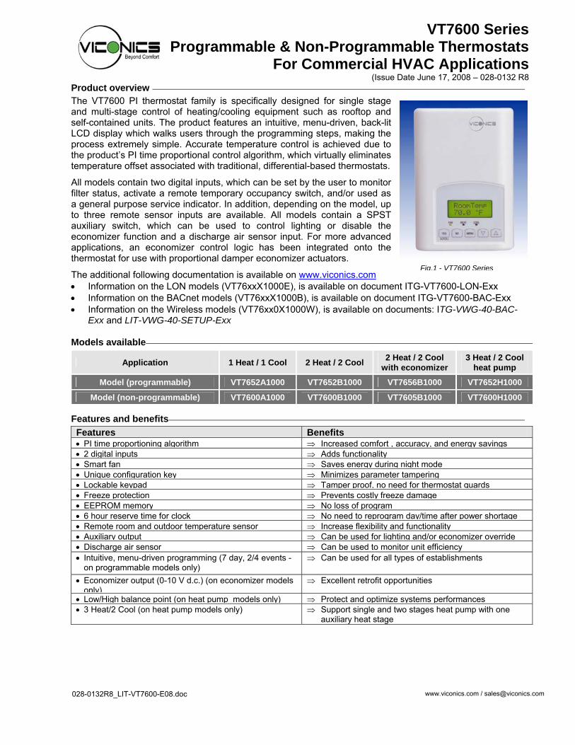
The VT7600 PI thermostat family is specifically designed for single stage and multi-stage control of heating/cooling equipment such as rooftop and self-contained units. The product features an intuitive, menu-driven, back-lit LCD display which walks users through the programming steps, making the process extremely simple. Accurate temperature control is achieved due to the product’s PI time proportional control algorithm, which virtually eliminates temperature offset associated with traditional, differential-based thermostats.
All models contain two digital inputs, which can be set by the user to monitor filter status, activate a remote temporary occupancy switch, and/or used as a general purpose service indicator. In addition, depending on the model, up to three remote sensor inputs are available. All models contain a SPST auxiliary switch, which can be used to control lighting or disable the economizer function and a discharge air sensor input. For more advanced applications, an economizer control logic has been integrated onto the thermostat for use with proportional damper economizer actuators.
The additional following documentation is available on www.viconics.com • Information on the LON models (VT76xxX1000E), is available on document ITG-VT7600-LON-Exx • Information on the BACnet models (VT76xxX1000B), is available on document ITG-VT7600-BAC-Exx • Information on the Wireless models (VT76xx0X1000W), is available on documents: ITG-VWG-40-BAC-
Exx and LIT-VWG-40-SETUP-Exx Models available
Application 1 Heat / 1 Cool 2 Heat / 2 Cool 2 Heat / 2 Cool with economizer
3 Heat / 2 Cool heat pump
Model (programmable) VT7652A1000 VT7652B1000 VT7656B1000 VT7652H1000
Model (non-programmable) VT7600A1000 VT7600B1000 VT7605B1000 VT7600H1000 Features and benefits
Features Benefits• PI time proportioning algorithm ⇒ Increased comfort , accuracy, and energy savings• 2 digital inputs ⇒ Adds functionality• Smart fan ⇒ Saves energy during night mode • Unique configuration key ⇒ Minimizes parameter tampering • Lockable keypad ⇒ Tamper proof, no need for thermostat guards• Freeze protection ⇒ Prevents costly freeze damage • EEPROM memory ⇒ No loss of program• 6 hour reserve time for clock ⇒ No need to reprogram day/time after power shortage• Remote room and outdoor temperature sensor ⇒ Increase flexibility and functionality • Auxiliary output ⇒ Can be used for lighting and/or economizer override• Discharge air sensor ⇒ Can be used to monitor unit efficiency • Intuitive, menu-driven programming (7 day, 2/4 events -
on programmable models only) ⇒ Can be used for all types of establishments
• Economizer output (0-10 V d.c.) (on economizer models only)
⇒ Excellent retrofit opportunities
• Low/High balance point (on heat pump models only) ⇒ Protect and optimize systems performances• 3 Heat/2 Cool (on heat pump models only) ⇒ Support single and two stages heat pump with one
auxiliary heat stage 028-0132R8_LIT-VT7600-E08.doc www.viconics.com / [email protected]
Fig.1 - VT7600 Series

2
Theory of operation
The VT7600 uses a Viconics proprietary adaptive logic algorithm to control the space temperature. This algorithm controls the heating / air conditioning system to minimize overshoot while still providing comfort. It provides exceptional accuracy due to its unique PI time proportioning control algorithm, which virtually eliminates temperature offset associated with traditional, differential-based on/off thermostats.
Fig.2 - On/Off mechanical control vs PI electronic control. Features overview
• 7 day programmable models, 2 or 4 events • Gas/oil or electric system compatibility for all type
of applications • Remote indoor averaging sensing capability • Temperature averaging with 2, 3, 4, 9 or 16
sensors • Remote outdoor sensing capability for added
flexibility - System mode lock out - Heat pump balance point settings
• Remote discharge air sensor input for monitoring purpose - System efficiency feedback
• Lockable keypads for tamper proofing. No need for thermostat guards
• Automatic frost protection to prevents costly freeze damage
• Anti short cycle and minimum on/off run time protection. Reduces wear and maximizes life span of mechanical equipment.
• 2 programmable digital inputs for added flexibility. Each input can be programmed as the following: - None: No function will be associated with the
input - Service: a backlit flashing Service alarm will be
displayed on the thermostat LCD screen when the input is energized. It can be tied in to the AC unit control card, which provides an alarm in case of malfunction.
- Filter: a backlit flashing Filter alarm will be displayed on the thermostat LCD screen when the input is energized. It can be tied to a differential pressure switch that monitor filters
- Rem NSB: remote NSB timer clock input. Will disable the internal scheduling of the thermostat. The scheduling will now be set as per the digital input. The menu part related to scheduling is disabled and no longer accessible. It provides low cost setback operation via occupancy sensor or from a dry contact
- RemOVR: temporary occupancy contact. Disables all override menu function of the thermostat. . The override function is now controlled by a manual remote momentarily closed contact. When configured in this mode, the input operates in a toggle mode. With this function enabled it is now possible to toggle between unoccupied & occupied setpoints for the amount of time set by parameter (TOccTime) temporary occupancy time. • Programmable smart fan operation saves
energy during night mode • Non volatile EEPROM memory prevents loss of
parameters during power shortage • Built in default profile set-up for easier start up
and commissioning • Configurable SPST output relay on
programmable models for lighting, exhaust fan or fresh air control
• 6 hour typical reserve time for clock in case of power loss
• 0 to 10 Vdc economizer output for more retrofit opportunities - Built in dry bulb economizer logic using
outdoor temperature sensor - Input for supply/mixed air temperature sensor
Heat pump model specific features
• Selectable single or dual stage compressor stages
• High balance point: Locks out auxiliary heating when outside air temperature is above this value
• Low balance point: Locks out heat pump compressor operation when outside air temperature is below this value
• Comfort/economy mode: In economy mode, heat pump use is maximized before turning On auxiliary heating
• Compressor/auxiliary interlock: Adds flexibility by locking out heat pump operation during auxiliary heating to prevent high pressure trip when the coil is downstream of the auxiliary heat source.
3Installation
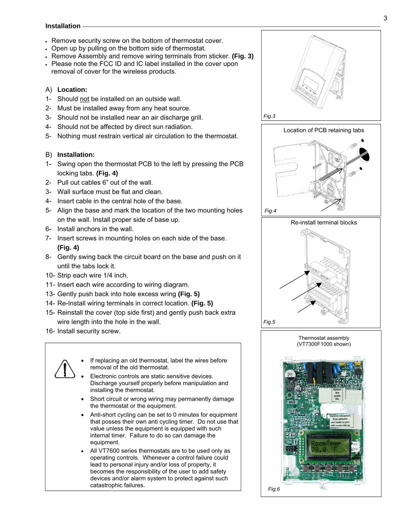
• Remove security screw on the bottom of thermostat cover. • Open up by pulling on the bottom side of thermostat. • Remove Assembly and remove wiring terminals from sticker. (Fig. 3) • Please note the FCC ID and IC label installed in the cover upon
removal of cover for the wireless products. A) Location: 1- Should not be installed on an outside wall. 2- Must be installed away from any heat source. 3- Should not be installed near an air discharge grill. 4- Should not be affected by direct sun radiation. 5- Nothing must restrain vertical air circulation to the thermostat. B) Installation: 1- Swing open the thermostat PCB to the left by pressing the PCB
locking tabs. (Fig. 4) 2- Pull out cables 6” out of the wall. 3- Wall surface must be flat and clean. 4- Insert cable in the central hole of the base. 5- Align the base and mark the location of the two mounting holes
on the wall. Install proper side of base up. 6- Install anchors in the wall. 7- Insert screws in mounting holes on each side of the base.
(Fig. 4) 8- Gently swing back the circuit board on the base and push on it
until the tabs lock it. 10- Strip each wire 1/4 inch. 11- Insert each wire according to wiring diagram. 13- Gently push back into hole excess wring (Fig. 5) 14- Re-Install wiring terminals in correct location. (Fig. 5) 15- Reinstall the cover (top side first) and gently push back extra
wire length into the hole in the wall. 16- Install security screw.
• If replacing an old thermostat, label the wires before removal of the old thermostat.
• Electronic controls are static sensitive devices. Discharge yourself properly before manipulation and installing the thermostat.
• Short circuit or wrong wiring may permanently damage the thermostat or the equipment.
• Anti-short cycling can be set to 0 minutes for equipment that posses their own anti cycling timer. Do not use that value unless the equipment is equipped with such internal timer. Failure to do so can damage the equipment.
• All VT7600 series thermostats are to be used only as operating controls. Whenever a control failure could lead to personal injury and/or loss of property, it becomes the responsibility of the user to add safety devices and/or alarm system to protect against such catastrophic failures.
Location of PCB retaining tabs
Re-install terminal blocks
Thermostat assembly
(VT7300F1000 shown)
Fig.6
Fig.3
Fig.5
Fig.4
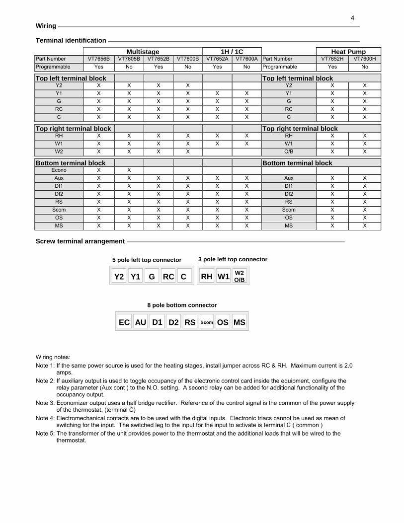
4Wiring Terminal identification
Multistage 1H / 1C Heat PumpPart Number VT7656B VT7605B VT7652B VT7600B VT7652A VT7600A Part Number VT7652H VT7600H Programmable Yes No Yes No Yes No Programmable Yes No
Top left terminal block Top left terminal blockY2 X X X X Y2 X X Y1 X X X X X X Y1 X X G X X X X X X G X X
RC X X X X X X RC X X C X X X X X X C X X
Top right terminal block Top right terminal blockRH X X X X X X RH X X W1 X X X X X X W1 X X W2 X X X X O/B X X
Bottom terminal block Bottom terminal blockEcono X X
Aux X X X X X X Aux X X DI1 X X X X X X DI1 X X DI2 X X X X X X DI2 X X RS X X X X X X RS X X
Scom X X X X X X Scom X X OS X X X X X X OS X X MS X X X X X X MS X X
Screw terminal arrangement
Wiring notes:
Note 1: If the same power source is used for the heating stages, install jumper across RC & RH. Maximum current is 2.0 amps.
Note 2: If auxiliary output is used to toggle occupancy of the electronic control card inside the equipment, configure the relay parameter (Aux cont ) to the N.O. setting. A second relay can be added for additional functionality of the occupancy output.
Note 3: Economizer output uses a half bridge rectifier. Reference of the control signal is the common of the power supply of the thermostat. (terminal C)
Note 4: Electromechanical contacts are to be used with the digital inputs. Electronic triacs cannot be used as mean of switching for the input. The switched leg to the input for the input to activate is terminal C ( common )
Note 5: The transformer of the unit provides power to the thermostat and the additional loads that will be wired to the thermostat.
EC AU D1 D2 RS Scom OS MS
Y2 Y1 G RC C RH W1 W2O/B
5 pole left top connector 3 pole left top connector
8 pole bottom connector
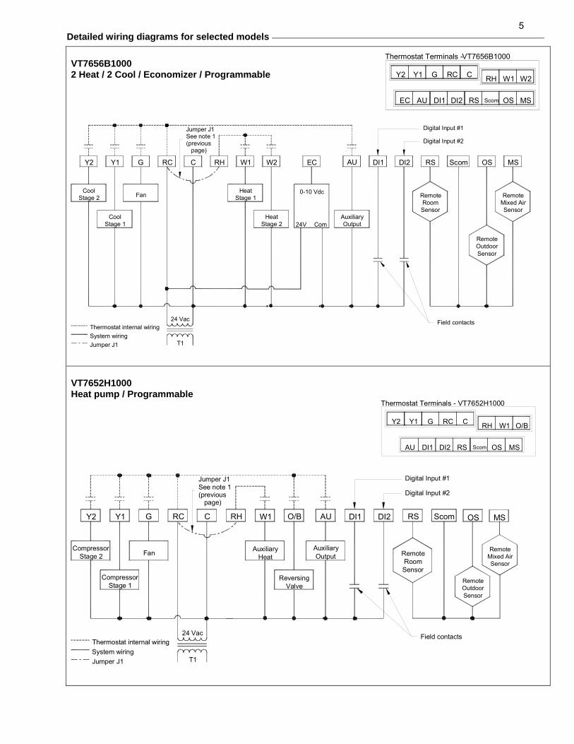
5Detailed wiring diagrams for selected models
VT7656B1000 2 Heat / 2 Cool / Economizer / Programmable
HeatStage 2
CoolStage 1
System wiringThermostat internal wiring
Jumper J1 T1
24 Vac
CoolStage 2
Y2 Y1
Jumper J1See note 1(previous page)
Fan
RCG C
HeatStage 1
W1RH W2
AuxiliaryOutput
Field contacts
Com24V
RemoteOutdoorSensor
Digital Input #2
Digital Input #1
RemoteRoomSensor
0-10 Vdc
EC AU DI1 DI2 RS
RemoteMixed AirSensor
MSScom OS
VT7652H1000 Heat pump / Programmable
AuxiliaryHeat
W1
System wiringJumper J1
Thermostat internal wiring
CompressorStage 1
24 Vac
T1
CompressorStage 2
Y2
Jumper J1See note 1(previous page)
Fan
GY1 RC C RH
RemoteRoomSensor
Field contacts
ReversingValve
Digital Input #2
Digital Input #1
AuxiliaryOutput
O/B AU DI1 DI2 ScomRS
RemoteOutdoorSensor
RemoteMixed AirSensor
MSOS
Thermostat Terminals - VT7652H1000
Y2
DI1 DI2AU
Y1 RCG O/B
OSRS Scom
RHC W1
MS
Thermostat Terminals -VT7656B1000
Y2
EC
RCGY1
AU DI1 DI2
W2
MS
W1RHC
ScomRS OS

6
AU
D1
RS
Scom
C
D2
Scom
RS
Scom
RS
C
DI
Aux
Scom
RS
Scom
RS
Scom
RS
Scom
RS
VT7600 Series Thermostat
2x S3010W1000 and 1x S3020W1000 Remote wiring 3 sensors S2-1 = OFF / S2-2 = OFF
AU
D1
RS
Scom
C
D2
Scom
RS
Scom
RS
C
DI
Aux
Scom
RS
Scom
RS
Scom
RS
Scom
RS
C
DI
Aux
VT7600 SeriesThermostat
1x S3010W1000 and 2x S3020W1000 Remote wiring 3 sensors S2-1 = OFF / S2-2 = OFF
Remote sensor accessories
Model no. Description S3010W1000 Wall mounted temperature sensor S3020W1000 Wall mounted temperature sensor with override button and occupancy status LED S2020E1000 Outdoor temperature sensor S2060A1000 Averaging temperature sensor S2000D1000 Duct mounted temperature sensor
Remote mount temperature sensors use 10K NTC thermistors.
• This sensor can be used for: • 3 thermistors with 2 dip switches are provided with each sensor for various
averaging combinations • Optional occupancy led • Optional override key
Fig.8 – S3020W1000 wall mounted sensor
Wiring example of single remote room sensor:
Wiring examples of 2 remote room sensors for averaging applications:
Wiring examples of 3 remote room sensors for averaging applications:
Notes for averaging applications:
• S3010W1000 and S3020W1000 can be mixed matched.
• S3010W1000 and S3020W1000 are to be wired in parallel.
• Respect the dip switch setting in each remote sensor.
AU
D1
RS
Scom
C
D2
Scom
RS
Scom
RS
C
DI
Aux
Scom
RS
Scom
RSOR
AU
D1
RS
Scom
C
D2
Scom
RS
Scom
RS
C
DI
Aux
Scom
RS
Scom
RS
C
DI
Aux
AU
D1
RS
Scom
C
D2
Scom
RS
Scom
RS
Scom
RS
Scom
RS
C
DI
Aux
VT7600 Series Thermostat
1x S3020W1000 Remote wiring 1 sensor S2-1 = ON / S2-2 = ON
S3010W1000 Remote wiring 1 sensor S2-1 = ON / S2-2 = ON
VT7600 Series Thermostat
2x S3020W1000 Remote wiring 2 sensors S2-1 = OFF / S2-2 = ON
AU
D1
RS
Scom
C
D2
Scom
RS
Scom
RS
Scom
RS
Scom
RS
2x S3010W1000 Remote wiring 2 sensors S2-1 = OFF / S2-2 = ON
VT7600 Series Thermostat
VT7600 Series Thermostat
1x S3010W1000 and 1x S3020W1000 Remote wiring 2 sensors S2-1 = OFF / S2-2 = ON
1 2
ONDip switch setting for:
1 sensor
S2-1 = ON
S2-2 = ON
1 2
ONDip switchsetting for:2 sensors
S2-1 = OFF
S2-2 = ON
1 2
ONDip switchsetting for:3 sensors
S2-1 = OFF
S2-2 = OFF
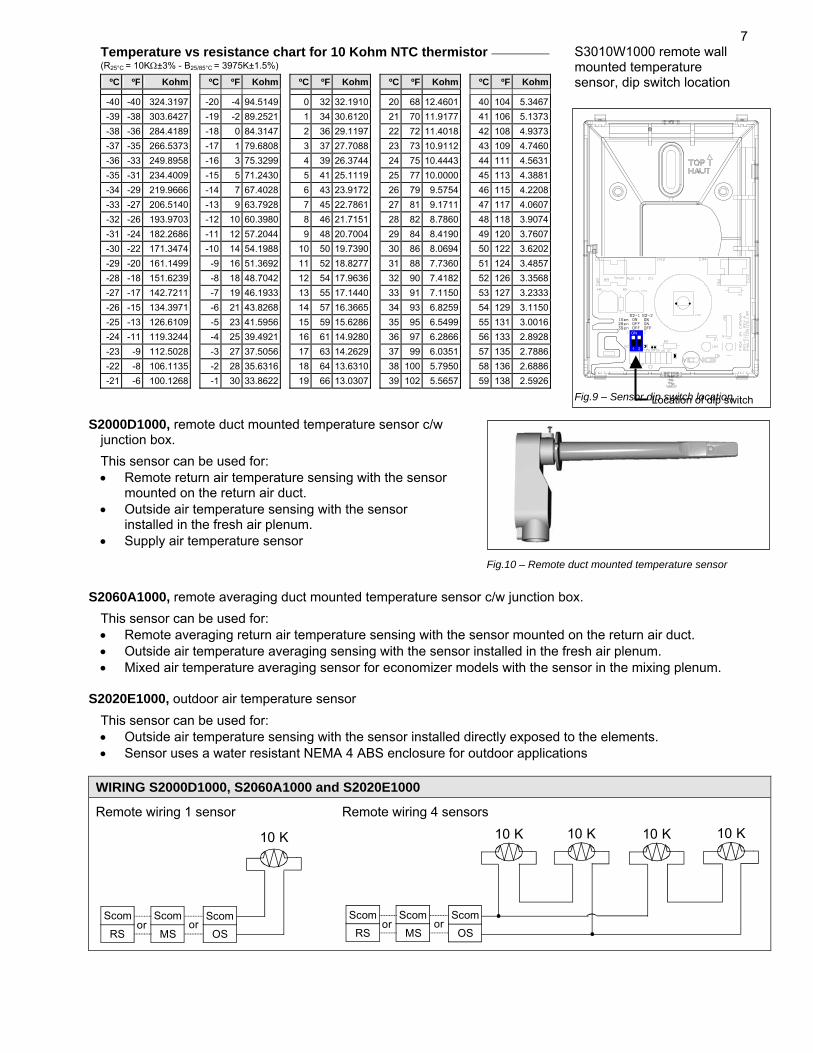
7Temperature vs resistance chart for 10 Kohm NTC thermistor (R25°C = 10KΩ±3% - B25/85°C = 3975K±1.5%)
ºC ºF Kohm ºC ºF Kohm ºC ºF Kohm ºC ºF Kohm ºC ºF Kohm
-40 -40 324.3197 -20 -4 94.5149 0 32 32.1910 20 68 12.4601 40 104 5.3467-39 -38 303.6427 -19 -2 89.2521 1 34 30.6120 21 70 11.9177 41 106 5.1373-38 -36 284.4189 -18 0 84.3147 2 36 29.1197 22 72 11.4018 42 108 4.9373-37 -35 266.5373 -17 1 79.6808 3 37 27.7088 23 73 10.9112 43 109 4.7460-36 -33 249.8958 -16 3 75.3299 4 39 26.3744 24 75 10.4443 44 111 4.5631-35 -31 234.4009 -15 5 71.2430 5 41 25.1119 25 77 10.0000 45 113 4.3881-34 -29 219.9666 -14 7 67.4028 6 43 23.9172 26 79 9.5754 46 115 4.2208-33 -27 206.5140 -13 9 63.7928 7 45 22.7861 27 81 9.1711 47 117 4.0607-32 -26 193.9703 -12 10 60.3980 8 46 21.7151 28 82 8.7860 48 118 3.9074-31 -24 182.2686 -11 12 57.2044 9 48 20.7004 29 84 8.4190 49 120 3.7607-30 -22 171.3474 -10 14 54.1988 10 50 19.7390 30 86 8.0694 50 122 3.6202-29 -20 161.1499 -9 16 51.3692 11 52 18.8277 31 88 7.7360 51 124 3.4857-28 -18 151.6239 -8 18 48.7042 12 54 17.9636 32 90 7.4182 52 126 3.3568-27 -17 142.7211 -7 19 46.1933 13 55 17.1440 33 91 7.1150 53 127 3.2333-26 -15 134.3971 -6 21 43.8268 14 57 16.3665 34 93 6.8259 54 129 3.1150-25 -13 126.6109 -5 23 41.5956 15 59 15.6286 35 95 6.5499 55 131 3.0016-24 -11 119.3244 -4 25 39.4921 16 61 14.9280 36 97 6.2866 56 133 2.8928-23 -9 112.5028 -3 27 37.5056 17 63 14.2629 37 99 6.0351 57 135 2.7886-22 -8 106.1135 -2 28 35.6316 18 64 13.6310 38 100 5.7950 58 136 2.6886-21 -6 100.1268 -1 30 33.8622 19 66 13.0307 39 102 5.5657 59 138 2.5926
S3010W1000 remote wall mounted temperature sensor, dip switch location
S2000D1000, remote duct mounted temperature sensor c/w junction box.
This sensor can be used for: • Remote return air temperature sensing with the sensor
mounted on the return air duct. • Outside air temperature sensing with the sensor
installed in the fresh air plenum. • Supply air temperature sensor
Fig.10 – Remote duct mounted temperature sensor
S2060A1000, remote averaging duct mounted temperature sensor c/w junction box.
This sensor can be used for: • Remote averaging return air temperature sensing with the sensor mounted on the return air duct. • Outside air temperature averaging sensing with the sensor installed in the fresh air plenum. • Mixed air temperature averaging sensor for economizer models with the sensor in the mixing plenum.
S2020E1000, outdoor air temperature sensor
This sensor can be used for: • Outside air temperature sensing with the sensor installed directly exposed to the elements. • Sensor uses a water resistant NEMA 4 ABS enclosure for outdoor applications
WIRING S2000D1000, S2060A1000 and S2020E1000
Remote wiring 1 sensor Remote wiring 4 sensors
10 K 10 K 10 K 10 K 10 K
Scom
MS
Scom
OS
Scom
RSoror
Scom
MS
Scom
OS
Scom
RSoror
(
Fig.9 – Sensor dip switch location
1 2
ON
Location of dip switch
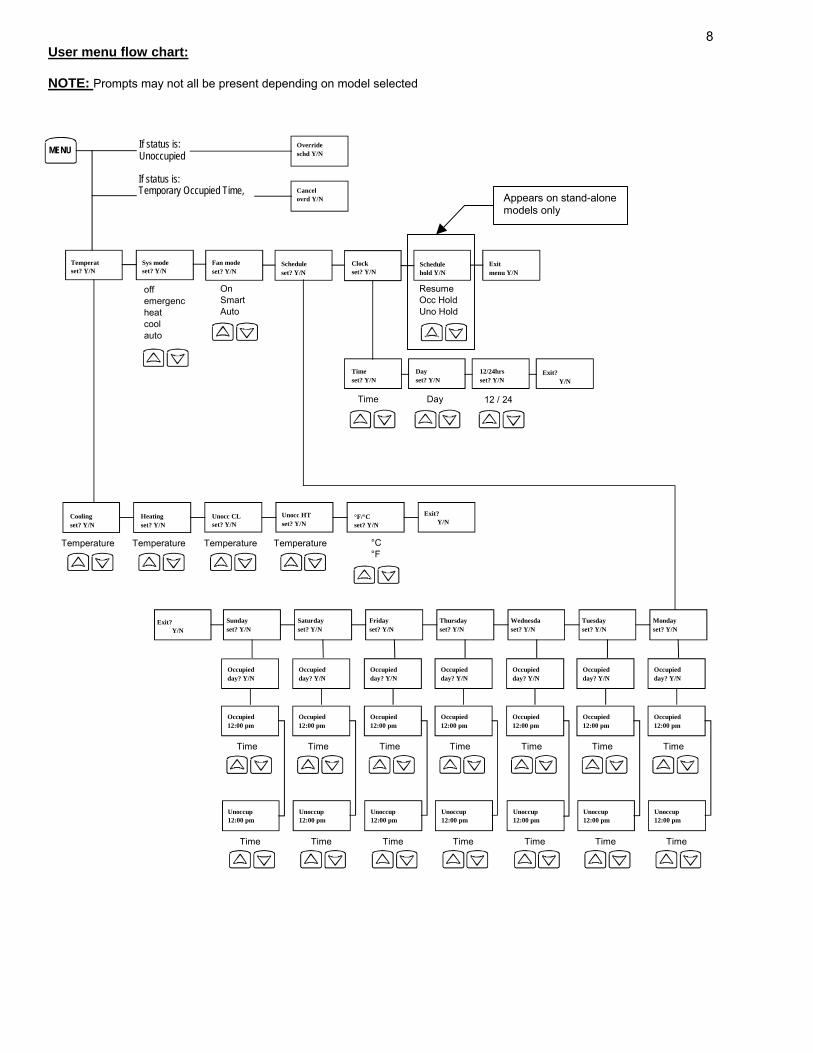
8User menu flow chart: NOTE: Prompts may not all be present depending on model selected
Schedule set? Y/N
Sys mode set? Y/N Clock
set? Y/NTemperat set? Y/N Schedule
hold Y/NExitmenu Y/N
Unocc HT set? Y/N °F/°C
set? Y/NHeating set? Y/N
Unocc CL set? Y/N Cooling
set? Y/N °C°F
Exit? Y/N
Temperature Temperature Temperature Temperature
MENU
12/24hrsset? Y/N
12 / 24
Timeset? Y/N
Time
Dayset? Y/N
Day
Fan mode set? Y/N
On SmartAuto
Sunday set? Y/N
Saturday set? Y/N
Fridayset? Y/N
Thursdayset? Y/N
Wednesdaset? Y/N
Tuesday set? Y/N
Mondayset? Y/N
Exit? Y/N
Occupied day? Y/N
Occupied 12:00 pm
Time
Unoccup 12:00 pm
Time
Occupied day? Y/N
Occupied 12:00 pm
Time
Unoccup 12:00 pm
Time
Occupiedday? Y/N
Occupied12:00 pm
Time
Unoccup12:00 pm
Time
Occupiedday? Y/N
Occupied12:00 pm
Time
Unoccup12:00 pm
Time
Occupiedday? Y/N
Occupied12:00 pm
Time
Unoccup12:00 pm
Time
Occupied day? Y/N
Occupied 12:00 pm
Time
Unoccup 12:00 pm
Time
Occupiedday? Y/N
Occupied12:00 pm
Time
Unoccup12:00 pm
Time
ResumeOcc HoldUno Hold
Exit? Y/N
off emergenc heat cool auto
Override schd Y/N
Cancel ovrd Y/N
If status is: Unoccupied
If status is: Temporary Occupied Time,
Appears on stand-alone models only
9Programming and status display instructions
1. Status display
The thermostat features a two-line, eight-character display. There is a low level back-light level that is always active and can only be seen at night. When left unattended, the thermostat has an auto scrolling display that shows the actual status of the system. Each item is scrolled one by one with the back lighting off. Pressing any key will cause the back light to come on. Sequence of auto-scroll status display:
Room temperature Clock status System mode Schedule status Outdoor temperature Alarms
RoomTemp Monday Sys mode Occupied Outdoor Service x.x °C or °F 12.00 AM auto x.x °C or°F
Sys mode off
Occupied hold Frost ON
Sys mode heat
Unoccup SetClock
Sys mode cool
Unoccup hold Filter
Sys mode emergenc Override
Manual scroll of each menu item is achieved by pressing the Yes ( scroll ) key repetitively. The last item viewed will be shown on the display for 30 seconds before returning to automatic scrolling. Temperature is automatically updated when scrolling is held.
Outdoor air temperature display is only enabled when outdoor air temperature sensor is connected. • A maximum range status display of 50 °C ( 122 °F ) indicates a shorted sensor. Associated functions, such as mode
lockouts and economizer function are automatically disabled. • A minimum range status -40 °C ( -40 °F ) is not displayed and indicates a opened sensor or a sensor not connected.
Associated functions, such as mode lockouts and economizer function are automatically disabled. If alarms are detected, they will automatically be displayed at the end of the status display scroll. During an alarm message display, the back lit screen will light up at the same time as the message and shut off during the rest of the status display. Two alarms maximum can appear at any given time. The priority for the alarms is as follows:
Frost ON Indicates that the heating is energized by the low limit frost protection room temperature setpoint 5.6 °C ( 42 °F ) SetClock Indicates that the clock needs to be reset. There has been a power failure which has lasted longer than 6 hours Service Indicates that there is a service alarm as per one of the programmable digital input ( DI1 or DI2 ) Filter Indicates that the filters are dirty as per one of the programmable digital input ( DI1 or DI2 )
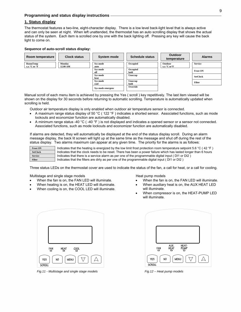
Three status LEDs on the thermostat cover are used to indicate the status of the fan, a call for heat, or a call for cooling. Multistage and single stage models • When the fan is on, the FAN LED will illuminate. • When heating is on, the HEAT LED will illuminate. • When cooling is on, the COOL LED will illuminate.
Fig.11 - Multistage and single stage models
Heat pump models • When the fan is on, the FAN LED will illuminate. • When auxiliary heat is on, the AUX HEAT LED
will illuminate. • When compressor is on, the HEAT-PUMP LED
will illuminate.
Fig.12 – Heat pump models

102. User programming instructions menu The VT7600 series of thermostat feature an intuitive, menu-driven, back-lit LCD display that walks users through the programming steps, making the programming process extremely simple. This menu is typically accessed by the user to set the parameters such as temperature and time events, system mode, fan mode, etc.
It is possible to bring up the user menu at any time by depressing the MENU key. The status display automatically resumes after exiting the user-programming menu.
If the user pauses at any given time during programming, Auto Help text is displayed to help and guide the user through the usage and programming of the thermostat.
Ex.:
Press yes key to change cooling temperature setpoint Use the up or down arrow to adjust cooling setpoint
Each of the sections in the menu are accessed and programmed using 5 keys on the thermostat cover. The priority for the alarms is as follows:
The YES key is used to confirm a selection, to move onto the next menu item and to manually scroll through the displayed information.
The NO key is used when you do not desire a parameter change, and to advance to the next menu item. Can also be used to toggle between heating and cooling setpoints.
The MENU key is used to access the Main User Menu or exit the menu.
The down arrow key is used to decrease temperature setpoint and to adjust the desired values when programming and configuring the thermostat.
The up arrow key is used to increase temperature setpoint and to adjust the desired values when programming and configuring the thermostat.
When left unattended for 45 seconds, the display will resume automatic status display scrolling. To turn on the back light, press any key on the front panel. The back lit display will turn off when the thermostat is left unattended for 45 seconds Sequence of user menu:
Override Resume Temperature
setpoints System mode setting Fan mode setting Schedules setting Clock setting Schedule hold
Override schd Y/N
Temperat set Y/N
Sys mode set Y/N
Fan mode set Y/N
Schedule set Y/N
Clock set Y/N
Schedule hold Y/N
Appears only in unoccupied mode
Appears only on stand-alone models
Cancel ovrd Y/N
Appears only in override mode
There is a default profile set in the thermostat from the factory. This enables the thermostat to operate as a non-programmable unit in day mode operation at start up.
Programmed default temperature setpoints: Programmed default modes:
Occupied cooling setpoint = 24 °C ( 75 °F ) System mode = Auto
Occupied heating setpoint = 22 °C ( 72 °F )
Unoccupied cooling setpoint = 28 °C ( 82 °F )
Fan mode = Smart (for models with a communication module or programmable stand-alone models)
Fan mode = Auto (for non-programmable stand-alone models)
Unoccupied heating setpoint = 18 °C ( 65 °F ) Programmed default schedules:
Fahrenheit scale Monday through Sunday
Setpoint type = permanent Occupied time is: 12 00 AM
Unoccupied time is: 11:59 PM
There will be a 1 minute unoccupied period every night at 11:59 PM with this default configuration.

11 A) Override an unoccupied period
Override schd Y/N
This menu will appear only when the thermostat is in unoccupied mode. The unoccupied mode is enabled either by the internal timer scheduling or by a remote NSB contact via DI1 or DI2. If DI1 or DI2 is configured to operate as a remote temporary override contact, this menu will be disabled.
Answering yes to this prompt will cause the thermostat to go into occupied mode for an amount of time equal to the parameter “TOccTime” (1 to 12 hours). B) Resume regular scheduling
Cancel ovrd Y/N
This menu does not appear in regular operation. It will appear only when the thermostat is in Unoccupied override mode.
Answering “Yes” to this question will cause the thermostat to resume the regular programmed setpoints & scheduling. C) Temperature setpoints Permanent setpoint changes
Temperat set Y/N
This menu permits the adjustment of all permanent temperature setpoints (occupied and unoccupied) as well as the desired temperature units (°F or °C). Permanent setpoints are written to RAM and EEPROM
Cooling setpoint Occupied mode
Heating setpoint Occupied mode
Cooling setpoint Unoccupied mode
Heating setpoint Unoccupied mode
°F or °C display setting
Cooling set? Y/N
No next → Yes down ↓
Heating set? Y/N
No next → Yes down ↓
Unocc CL set? Y/N
No next → Yes down ↓
Unocc HT set? Y/N
No next → Yes down ↓
°F or °C set? Y/N
No next → Yes down ↓
Use ▲▼ keys to set value, Yes key to confirm Cooling 70.0 °F
Use ▲▼ To set value
Heating 68.00 °F
Use ▲▼ To set value
Unocc CL 80.0 °F
Use ▲▼ To set value
Unocc HT 60.0 °F
Use ▲▼ To set value
Units °F
Use ▲▼ To set value
Temporary setpoint changes Temporary setpoints can be modified through the Up arrow key (▲) and the Down arrow keys (▼). User will be prompted with the present mode (Heating or Cooling) of the thermostat and its setpoint. The Up (▲) arrow key will increment the setpoint by 0.5 degree (F or C). The Down (▼) arrow key will decrement the setpoint by 0.5 degree (F or C). Press the Yes key to accept the new setpoint. Local changes to the heating or cooling setpoints made by the user directly using the up or down arrow are temporary. They will remain effective for the duration specified by ToccTime. Setpoints will revert back to their default value after internal timer ToccTime expires. If a permanent change to the setpoints is required, use the Temperat set ? menu D) System mode setting
Sys mode set Y/N
This menu is accessed to set system mode operation Use ▲▼ to set value, Yes key to confirm
Sys mode auto
Automatic mode Automatic changeover mode between heating and cooling operation
Sys mode cooling
Cooling mode Cooling operation mode only
Sys mode heating
Heating mode Heating operation mode only
Sys mode emergency
Emergency heat mode ( heat pump models only ) Forced auxiliary heat operation mode only
Sys mode off
Off mode Normal cooling or heating operation disabled If enabled in installer parameters, only the automatic heating frost protection at 50 °F ( 10 °C ) is enabled

12
E) Fan mode setting
Fan mode set Y/N
This section of the menu is permits the setting of the fan mode operation. Use ▲▼ to set value, Yes key to confirm
Fan mode On
On fan mode Fan is on continuously, even when system mode is OFF.
Fan mode Auto
Automatic fan mode Fan cycles on a call for heating or cooling for both occupied & unoccupied periods.
Fan mode Smart
Smart fan mode During occupied periods, fan is on continuously. In unoccupied mode, fan cycles on a call for heating or cooling. This selection is available on all models with a communication module, on all stand-alone programmable models or if DI1 or DI2 is set to RemNSB on stand-alone non-programmable models
F) Schedule set (2 events) Scheduling can have 2 or 4 events per day. This is set in the configuration menu as per parameter (2/4event )
Schedule set Y/N
This section of the menu permits the user to set the whether 2 or 4 events is needed. Each day can be tailored to specific schedules if needed. • 2 events can be programmed per day. • Occupied & unoccupied periods can be set for each day.
Monday timer Schedule set
Tuesday timer Schedule set
Wednesday timer Schedule set
Other days are identical
Monday set? Y/N
No next → Yes down ↓
Tuesday set? Y/N
No next → Yes down ↓
Wednesda set? Y/N
No next → Yes down ↓
Selects the day to be programmed or modified
Yes key to access day scheduling, No key to jump to next day Occupied Day? Y/N
No next → Yes down ↓
Occupied Day? Y/N
No next → Yes down ↓
Occupied Day? Y/N
No next → Yes down ↓
Yes = Daily schedules will be accessed No = Unoccupied mode all day
Yes key to access day scheduling, No key to jump to next day
Copy Y/N Previous
Yes next → No down ↓
Copy Y/N Previous
Yes next → No down ↓
Yes = Will copy previous day schedule No = Daily schedules will be accessed
Yes key to copy previous day, No key to set new time value for each day Occupied 00:00 AM
Use ▲▼ To set value
Occupied 00:00 AM
Use ▲▼ To set value
Occupied 00:00 AM
Use ▲▼ To set value
Sets Event # 1 Occupied time Will activate occupied setpoints
Use ▲▼ to set value, Yes key to confirm Unoccup 00:00 AM
Use ▲▼ To set value
Unoccup 00:00 AM
Use ▲▼ To set value
Unoccup 00:00 AM
Use ▲▼ To set value
Sets Event # 2 Unoccupied time Will activate unoccupied setpoints
Use ▲▼ to set value, Yes key to confirm Typical examples of a 2 event office schedule Ex. #1 Office building closed all weekend
Event Period #1 - Event #1 Period #1 - Event #2 Occupied Unoccupied
Cool Heat Cool Heat Daily Setpoint 72 °F 70 °F 80 °F 62 °F Occupancy Monday 7.00 AM 6.00 PM Day time only Tuesday 7.00 AM 6.00 PM Day time only Wednesday 7.00 AM 6.00 PM Day time only Thursday 7.00 AM 6.00 PM Day time only Friday 7.00 AM 6.00 PM Day time only Saturday 12.00 PM * 12.00 PM * Unoccupied Sunday 12.00 PM * 12.00 PM * Unoccupied
* Programming consecutive events to the same time will cause the thermostat to choose the last event as the time at which it will set its schedule. In the above example, the thermostat will control to the unoccupied set point until 7:00 AM Monday.
Ex. #2 Commercial building which is occupied all weekend Event Period #1 - Event #1 Period #1 - Event #2 Occupied Unoccupied
Cool Heat Cool Heat Daily Setpoint 72 °F 70 °F 80 °F 62 °F Occupancy Monday 8.00 AM 5.00 PM Day time only Tuesday 8.00 AM 5.00 PM Day time only Wednesday 8.00 AM 5.00 PM Day time only Thursday 8.00 AM 5.00 PM Day time only Friday 8.00 AM 5.00 PM Day time only Saturday 12.00 AM ** 11.59 PM ** Occupied Sunday 12.00 AM ** 11.59 PM ** Occupied
** To program a day as occupied for 24 hours, set that day Occupied time to 12:00 AM and Unoccupied time to 11:59 PM There will be a 1 minute unoccupied period every night at 11:59 PM with this schedule configuration.
Note: 12:00 PM = Noon 12:00 AM = Midnight
13
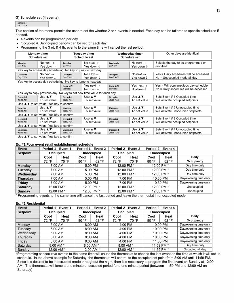
G) Schedule set (4 events)
Schedule set Y/N
This section of the menu permits the user to set the whether 2 or 4 events is needed. Each day can be tailored to specific schedules if needed. • 4 events can be programmed per day. • Occupied & Unoccupied periods can be set for each day. • Programming the 3 rd. & 4 th. events to the same time will cancel the last period.
Monday timer Schedule set
Tuesday timer Schedule set
Wednesday timer Schedule set
Other days are identical
Monday set? Y/N
No next → Yes down ↓
Tuesday set? Y/N
No next → Yes down ↓
Wednesda set? Y/N
No next → Yes down ↓
Selects the day to be programmed or modified
Yes key to access day scheduling, No key to jump to next day Occupied Day? Y/N
No next → Yes down ↓
Occupied Day? Y/N
No next → Yes down ↓
Occupied Day? Y/N
No next → Yes down ↓
Yes = Daily schedules will be accessed No = Unoccupied mode all day
Yes key to access day scheduling, No key to jump to next day
Copy Y/N Previous
Yes next → No down ↓
Copy Y/N Previous
Yes next → No down ↓
Yes = Will copy previous day schedule No = Daily schedules will be accessed
Yes key to copy previous day, No key to set new time value for each day Occupied 00:00 AM
Use ▲▼ To set value
Occupied 00:00 AM
Use ▲▼ To set value
Occupied 00:00 AM
Use ▲▼ To set value
Sets Event # 1 Occupied time Will activate occupied setpoints
Use ▲▼ to set value, Yes key to confirm Unoccup 00:00 AM
Use ▲▼ To set value
Unoccup 00:00 AM
Use ▲▼ To set value
Unoccup 00:00 AM
Use ▲▼ To set value
Sets Event # 2 Unoccupied time Will activate unoccupied setpoints
Use ▲▼ to set value, Yes key to confirm Occupie2 00:00 AM
Use ▲▼ To set value
Occupie2 00:00 AM
Use ▲▼ To set value
Occupie2 00:00 AM
Use ▲▼ To set value
Sets Event # 3 Occupied time Will activate occupied setpoints
Use ▲▼ to set value, Yes key to confirm Unoccup2 00:00 AM
Use ▲▼ To set value
Unoccup2 00:00 AM
Use ▲▼ To set value
Unoccup2 00:00 AM
Use ▲▼ To set value
Sets Event # 4 Unoccupied time Will activate unoccupied setpoints
Use ▲▼ to set value, Yes key to confirm Ex. #1 Four event retail establishment schedule
Event Period 1 - Event 1 Period 1 - Event 2 Period 2 - Event 3 Period 2 - Event 4 Setpoint Occupied Unoccupied Occupied Unoccupied Cool Heat Cool Heat Cool Heat Cool Heat Daily 72 °F 70 °F 80 °F 62 °F 72 °F 70 °F 80 °F 62 °F Occupancy Monday 7.00 AM 5.00 PM 12.00 PM * 12.00 PM * Day time only Tuesday 7.00 AM 5.00 PM 12.00 PM * 12.00 PM * Day time only Wednesday 7.00 AM 5.00 PM 12.00 PM * 12.00 PM * Day time only Thursday 7.00 AM 5.00 PM 7.00 PM 10.30 PM Day/evening time only Friday 7.00 AM 5.00 PM 7.00 PM 10.30 PM Day/evening time only Saturday 12.00 PM * 12.00 PM * 12.00 PM * 12.00 PM * Unoccupied Sunday 12.00 PM * 12.00 PM * 12.00 PM * 12.00 PM * Unoccupied
* Programming events to the same time will cancel the last period and leave the thermostat in unoccupied mode Ex. #2 Residential
Event Period 1 - Event 1 Period 1 - Event 2 Period 2 - Event 3 Period 2 - Event 4 Setpoint Occupied Unoccupied Occupied Unoccupied Cool Heat Cool Heat Cool Heat Cool Heat Daily 72 °F 70 °F 80 °F 62 °F 72 °F 70 °F 80 °F 62 °F Occupancy Monday 6:00 AM 8:00 AM 4:00 PM 10:00 PM Day/evening time only Tuesday 6:00 AM 8:00 AM 4:00 PM 10:00 PM Day/evening time only Wednesday 6:00 AM 8:00 AM 4:00 PM 10:00 PM Day/evening time only Thursday 6:00 AM 8:00 AM 4:00 PM 10:00 PM Day/evening time only Friday 6:00 AM 8:00 AM 4:00 PM 11:30 PM Day/evening time only Saturday 8:00 AM * 8:00 AM * 8:00 AM * 11:59 PM * Day time only Sunday 12:00 AM * 12:00 AM * 12:00 AM * 11:59 PM * Occupied all day
* Programming consecutive events to the same time will cause the thermostat to choose the last event as the time at which it will set its schedule. In the above example for Saturday, the thermostat will control to the occupied set point from 8:00 AM until 11:59 PM. Since it is desired to be in occupied mode throughout the night, then it is necessary to program the first event on Sunday at 12:00 AM. The thermostat will force a one minute unoccupied period for a one minute period (between 11:59 PM and 12:00 AM on Saturday)
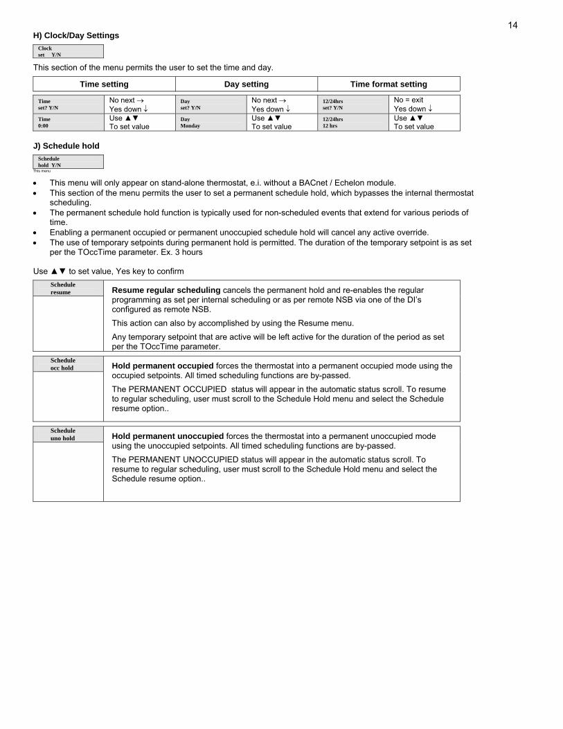
14H) Clock/Day Settings
Clock set Y/N
This section of the menu permits the user to set the time and day.
Time setting Day setting Time format setting
Time set? Y/N
No next → Yes down ↓
Day set? Y/N
No next → Yes down ↓
12/24hrs set? Y/N
No = exit Yes down ↓
Time 0:00
Use ▲▼ To set value
Day Monday
Use ▲▼ To set value
12/24hrs 12 hrs
Use ▲▼ To set value
J) Schedule hold
Schedule hold Y/N
This menu
• This menu will only appear on stand-alone thermostat, e.i. without a BACnet / Echelon module. • This section of the menu permits the user to set a permanent schedule hold, which bypasses the internal thermostat
scheduling. • The permanent schedule hold function is typically used for non-scheduled events that extend for various periods of
time. • Enabling a permanent occupied or permanent unoccupied schedule hold will cancel any active override. • The use of temporary setpoints during permanent hold is permitted. The duration of the temporary setpoint is as set
per the TOccTime parameter. Ex. 3 hours Use ▲▼ to set value, Yes key to confirm
Schedule resume
Resume regular scheduling cancels the permanent hold and re-enables the regular programming as set per internal scheduling or as per remote NSB via one of the DI’s configured as remote NSB.
This action can also by accomplished by using the Resume menu.
Any temporary setpoint that are active will be left active for the duration of the period as set per the TOccTime parameter.
Schedule occ hold
Hold permanent occupied forces the thermostat into a permanent occupied mode using the occupied setpoints. All timed scheduling functions are by-passed.
The PERMANENT OCCUPIED status will appear in the automatic status scroll. To resume to regular scheduling, user must scroll to the Schedule Hold menu and select the Schedule resume option..
Schedule uno hold
Hold permanent unoccupied forces the thermostat into a permanent unoccupied mode using the unoccupied setpoints. All timed scheduling functions are by-passed.
The PERMANENT UNOCCUPIED status will appear in the automatic status scroll. To resume to regular scheduling, user must scroll to the Schedule Hold menu and select the Schedule resume option..
15
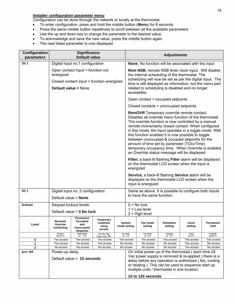
Installer configuration parameter menu Configuration can be done through the network or locally at the thermostat. • To enter configuration, press and hold the middle button (Menu) for 8 seconds • Press the same middle button repetitively to scroll between all the available parameters • Use the up and down key to change the parameter to the desired value. • To acknowledge and save the new value, press the middle button again. • The next listed parameter is now displayed
Configuration
parameters Significance Default value Adjustments
DI 1
Digital input no.1 configuration
Open contact input = function not energized
Closed contact input = function energized
Default value = None
None, No function will be associated with the input
Rem NSB, remote NSB timer clock input. Will disable the internal scheduling of the thermostat. The scheduling will now be set as per the digital input. The time is still displayed as information, but the menu part related to scheduling is disabled and no longer accessible.
Open contact = occupied setpoints
Closed contacts = unoccupied setpoints
RemOVR Temporary override remote contact. Disables all override menu function of the thermostat. The override function is now controlled by a manual remote momentarily closed contact. When configured in this mode, the input operates in a toggle mode. With this function enabled it is now possible to toggle between unoccupied & occupied setpoints for the amount of time set by parameter (TOccTime) temporary occupancy time. When Override is enabled, an Override status message will be displayed
Filter, a back-lit flashing Filter alarm will be displayed on the thermostat LCD screen when the input is energized
Service, a back-lit flashing Service alarm will be displayed on the thermostat LCD screen when the input is energized
DI 2 Digital input no. 2 configuration
Default value = None
Same as above. It is possible to configure both inputs to have the same function.
lockout Keypad lockout levels
Default value = 0 No lock
0 = No lock 1 = Low level 2 = High level
Level Resume/ Override
scheduling
Permanent Occupied
and Unoccupied
Setpoints
Temporary setpoints
using arrows
System mode setting
Fan mode setting
Schedules setting
Clock setting
Permanent hold
Resume sched Y/N
RoomTemp set Y/N
Up key (▲) Down key (▼)
Sys mode set Y/N
Fan mode set Y/N
Schedule set Y/N
Clock set Y/N
Schedule hold Y/N
0 Yes access Yes access Yes access Yes access Yes access Yes access Yes access Yes access 1 Yes access No access Yes access No access No access No access Yes access No access 2 No access No access No access No access No access No access Yes access No access
pwr del Power-up delay
Default value = 10 seconds
On initial power up of the thermostat ( each time 24 Vac power supply is removed & re-applied ) there is a delay before any operation is authorized ( fan, cooling or heating ). This can be used to sequence start up multiple units / thermostat in one location.
10 to 120 seconds
16
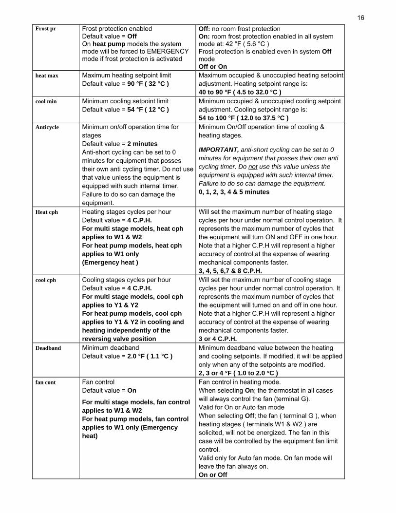
Frost pr Frost protection enabled Default value = Off On heat pump models the system mode will be forced to EMERGENCY mode if frost protection is activated
Off: no room frost protection On: room frost protection enabled in all system mode at: 42 °F ( 5.6 °C ) Frost protection is enabled even in system Off mode Off or On
heat max Maximum heating setpoint limit Default value = 90 °F ( 32 °C )
Maximum occupied & unoccupied heating setpoint adjustment. Heating setpoint range is: 40 to 90 °F ( 4.5 to 32.0 °C )
cool min Minimum cooling setpoint limit Default value = 54 °F ( 12 °C )
Minimum occupied & unoccupied cooling setpoint adjustment. Cooling setpoint range is: 54 to 100 °F ( 12.0 to 37.5 °C )
Anticycle Minimum on/off operation time for stages Default value = 2 minutes Anti-short cycling can be set to 0 minutes for equipment that posses their own anti cycling timer. Do not use that value unless the equipment is equipped with such internal timer. Failure to do so can damage the equipment.
Minimum On/Off operation time of cooling & heating stages. IMPORTANT, anti-short cycling can be set to 0 minutes for equipment that posses their own anti cycling timer. Do not use this value unless the equipment is equipped with such internal timer. Failure to do so can damage the equipment. 0, 1, 2, 3, 4 & 5 minutes
Heat cph Heating stages cycles per hour Default value = 4 C.P.H. For multi stage models, heat cph applies to W1 & W2 For heat pump models, heat cph applies to W1 only (Emergency heat )
Will set the maximum number of heating stage cycles per hour under normal control operation. It represents the maximum number of cycles that the equipment will turn ON and OFF in one hour. Note that a higher C.P.H will represent a higher accuracy of control at the expense of wearing mechanical components faster. 3, 4, 5, 6,7 & 8 C.P.H.
cool cph Cooling stages cycles per hour Default value = 4 C.P.H. For multi stage models, cool cph applies to Y1 & Y2 For heat pump models, cool cph applies to Y1 & Y2 in cooling and heating independently of the reversing valve position
Will set the maximum number of cooling stage cycles per hour under normal control operation. It represents the maximum number of cycles that the equipment will turned on and off in one hour. Note that a higher C.P.H will represent a higher accuracy of control at the expense of wearing mechanical components faster. 3 or 4 C.P.H.
Deadband Minimum deadband Default value = 2.0 °F ( 1.1 °C )
Minimum deadband value between the heating and cooling setpoints. If modified, it will be applied only when any of the setpoints are modified. 2, 3 or 4 °F ( 1.0 to 2.0 °C )
fan cont Fan control Default value = On
For multi stage models, fan control applies to W1 & W2 For heat pump models, fan control applies to W1 only (Emergency heat)
Fan control in heating mode. When selecting On; the thermostat in all cases will always control the fan (terminal G). Valid for On or Auto fan mode When selecting Off; the fan ( terminal G ), when heating stages ( terminals W1 & W2 ) are solicited, will not be energized. The fan in this case will be controlled by the equipment fan limit control. Valid only for Auto fan mode. On fan mode will leave the fan always on. On or Off
17
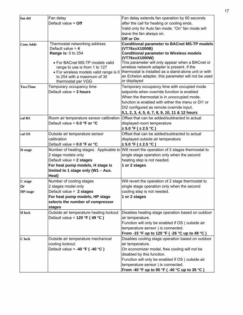
fan del Fan delay Default value = Off
Fan delay extends fan operation by 60 seconds after the call for heating or cooling ends. Valid only for Auto fan mode. “On” fan mode will leave the fan always on. Off or On
Com Addr Thermostat networking address Default value = 4 Range is: 0 to 254
• For BACnet MS-TP models valid range to use is from 1 to 127
• For wireless models valid range is 0 to 254 with a maximum of 30 thermostat per VGG
Conditional parameter to BACnet MS-TP models(VT76xxX1000B) Conditional parameter to Wireless models (VT76xxX1000W) This parameter will only appear when a BACnet or wireless network adapter is present. If the thermostat is installed as a stand-alone unit or with an Echelon adapter, this parameter will not be used or displayed
ToccTime Temporary occupancy time Default value = 3 hours
Temporary occupancy time with occupied mode setpoints when override function is enabled When the thermostat is in unoccupied mode, function is enabled with either the menu or DI1 or DI2 configured as remote override input. 0,1, 2, 3, 4, 5, 6, 7, 8, 9, 10, 11 & 12 hours
cal RS Room air temperature sensor calibrationDefault value = 0.0 °F or °C
Offset that can be added/subtracted to actual displayed room temperature ± 5.0 °F ( ± 2.5 °C )
cal OS Outside air temperature sensor calibration Default value = 0.0 °F or °C
Offset that can be added/subtracted to actual displayed outside air temperature ± 5.0 °F ( ± 2.5 °C )
H stage Number of heating stages. Applicable to 2 stage models only Default value = 2 stages For heat pump models, H stage is limited to 1 stage only (W1 – Aux. Heat)
Will revert the operation of 2 stages thermostat to single stage operation only when the second heating step is not needed. 1 or 2 stages
C stage Or HP stage
Number of cooling stages 2 stages model only Default value = 2 stages For heat pump models, HP stage selects the number of compressor stages
Will revert the operation of 2 stage thermostat to single stage operation only when the second cooling step is not needed. 1 or 2 stages
H lock Outside air temperature heating lockout Default value = 120 °F ( 49 °C )
Disables heating stage operation based on outdoor air temperature. Function will only be enabled if OS ( outside air temperature sensor ) is connected. From -15 °F up to 120 °F ( -26 °C up to 49 °C )
C lock Outside air temperature mechanical cooling lockout. Default value = -40 °F ( -40 °C )
Disables cooling stage operation based on outdoor air temperature. On economizer model, free cooling will not be disabled by this function. Function will only be enabled if OS ( outside air temperature sensor ) is connected. From -40 °F up to 95 °F ( -40 °C up to 35 °C )
18
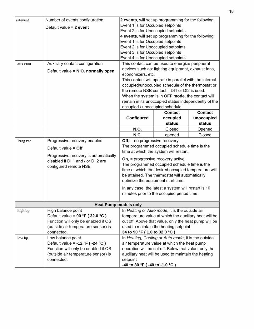
2/4event Number of events configuration Default value = 2 event
2 events, will set up programming for the following Event 1 is for Occupied setpoints Event 2 is for Unoccupied setpoints 4 events, will set up programming for the following Event 1 is for Occupied setpoints Event 2 is for Unoccupied setpoints Event 3 is for Occupied setpoints Event 4 is for Unoccupied setpoints
aux cont Auxiliary contact configuration
Default value = N.O. normally open
This contact can be used to energize peripheral devices such as: lighting equipment, exhaust fans, economizers, etc. This contact will operate in parallel with the internal occupied/unoccupied schedule of the thermostat or the remote NSB contact if DI1 or DI2 is used. When the system is in OFF mode, the contact will remain in its unoccupied status independently of the occupied / unoccupied schedule.
Configured
Contact occupied
status
Contact unoccupied
status N.O. Closed Opened N.C. opened Closed Prog rec Progressive recovery enabled
Default value = Off
Progressive recovery is automatically disabled if DI 1 and / or DI 2 are configured remote NSB
Off, = no progressive recovery The programmed occupied schedule time is the time at which the system will restart.
On, = progressive recovery active. The programmed occupied schedule time is the time at which the desired occupied temperature will be attained. The thermostat will automatically optimize the equipment start time.
In any case, the latest a system will restart is 10 minutes prior to the occupied period time.
Heat Pump models only high bp High balance point
Default value = 90 °F ( 32.0 °C ) Function will only be enabled if OS (outside air temperature sensor) is connected.
In Heating or Auto mode, it is the outside air temperature value at which the auxiliary heat will be cut off. Above that value, only the heat pump will be used to maintain the heating setpoint 34 to 90 °F ( 1.0 to 32.0 °C )
low bp Low balance point Default value = -12 °F ( -24 °C ) Function will only be enabled if OS (outside air temperature sensor) is connected.
In Heating, Cooling or Auto mode, it is the outside air temperature value at which the heat pump operation will be cut off. Below that value, only the auxiliary heat will be used to maintain the heating setpoint -40 to 30 °F ( -40 to -1.0 °C )

19
Comf/eco
Comfort or economy mode Default value = Comfort
Sets the operation and interaction mode of the heat pump with the auxiliary heat. Comfort mode. In Heating mode. If the heat pump is not able to satisfy the heating setpoint, the auxiliary heat will be energized to satisfy the same heating setpoint. Economy mode. In Heating mode. If the heat pump is not able to satisfy the heating setpoint, the auxiliary heat will be energized to satisfy only when the temperature has dropped 2.0 °F ( 1.1 °C ) below the heating setpoint. Selecting economy mode will add a deadband between the heatpump & auxiliary heat in heating mode. The actual temperature maintained will be lower than the true heating setpoint to maximize the heat pump operation. When the outdoor air temperature drops below the low balance point, the deadband will be eliminated and the auxiliary heat will maintain the true heating setpoint alone. Economy mode. In Emergency mode. If Emergency heat mode is selected, the setpoint maintained, will be the heating setpoint.
re valve Reversing valve operation O/B Default value = O
Heat pump reversing valve operation O will energize the valve in cooling operation. B will energize the valve in heating operation O or B
comp/aux Compressor/auxiliary interlock Default value = Off
Sets the operation and interaction mode of the heat pump with the auxiliary heat. Interlock Off. In Heating mode. If the heat pump is not able to satisfy the heating setpoint, the auxiliary heat will be energized at the same time as the heat pump stage. Typically applies when the air handler heat pump coil is installed before the auxiliary heat. ( all electric systems ) Interlock On. In Heating mode. If the heat pump is not able to satisfy the heating setpoint, the auxiliary heat will be energized and the heat pump will be cut off. Typically applies when the air handler heat pump coil is installed after the auxiliary heat. ( add on systems ) There is a 2 minute delay to restart the heat pump, when the auxiliary heat is shut down Off or On
Notes for Heat Pump models: When the outside air sensor is not connected or is shorted, the thermostat bypasses: • The heating lockout • The cooling lockout • The low balance point • The high balance point
Heat Pump model when set in Emergency mode bypasses heating lockout and permits auxiliary heating whenever a heating demand occurs.
20
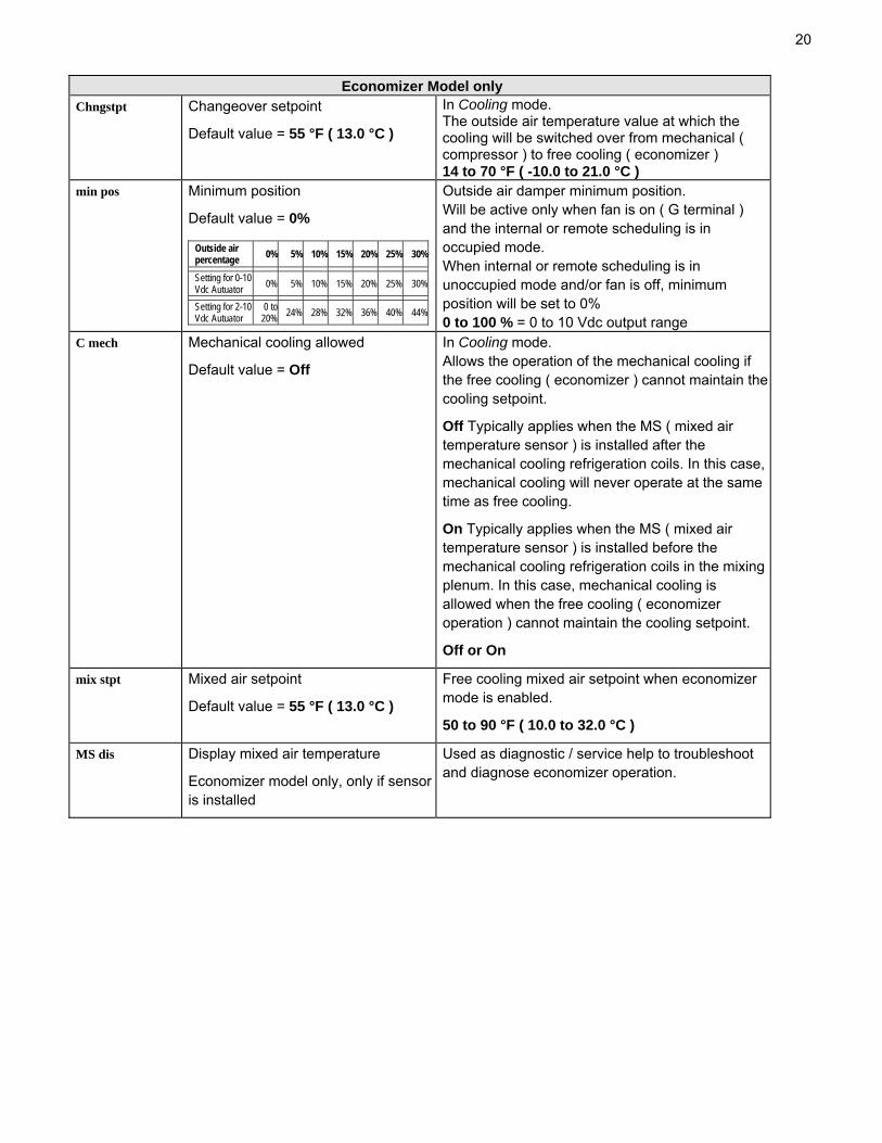
Economizer Model only Chngstpt Changeover setpoint
Default value = 55 °F ( 13.0 °C )
In Cooling mode. The outside air temperature value at which the cooling will be switched over from mechanical ( compressor ) to free cooling ( economizer ) 14 to 70 °F ( -10.0 to 21.0 °C )
min pos Minimum position
Default value = 0%
Outside air damper minimum position. Will be active only when fan is on ( G terminal ) and the internal or remote scheduling is in occupied mode. When internal or remote scheduling is in unoccupied mode and/or fan is off, minimum position will be set to 0% 0 to 100 % = 0 to 10 Vdc output range
C mech Mechanical cooling allowed
Default value = Off
In Cooling mode. Allows the operation of the mechanical cooling if the free cooling ( economizer ) cannot maintain the cooling setpoint.
Off Typically applies when the MS ( mixed air temperature sensor ) is installed after the mechanical cooling refrigeration coils. In this case, mechanical cooling will never operate at the same time as free cooling.
On Typically applies when the MS ( mixed air temperature sensor ) is installed before the mechanical cooling refrigeration coils in the mixing plenum. In this case, mechanical cooling is allowed when the free cooling ( economizer operation ) cannot maintain the cooling setpoint.
Off or On
mix stpt Mixed air setpoint
Default value = 55 °F ( 13.0 °C )
Free cooling mixed air setpoint when economizer mode is enabled.
50 to 90 °F ( 10.0 to 32.0 °C )
MS dis Display mixed air temperature
Economizer model only, only if sensor is installed
Used as diagnostic / service help to troubleshoot and diagnose economizer operation.
Outside air percentage 0% 5% 10% 15% 20% 25% 30%
Setting for 0-10 Vdc Autuator 0% 5% 10% 15% 20% 25% 30%
Setting for 2-10 Vdc Autuator
0 to 20% 24% 28% 32% 36% 40% 44%
21
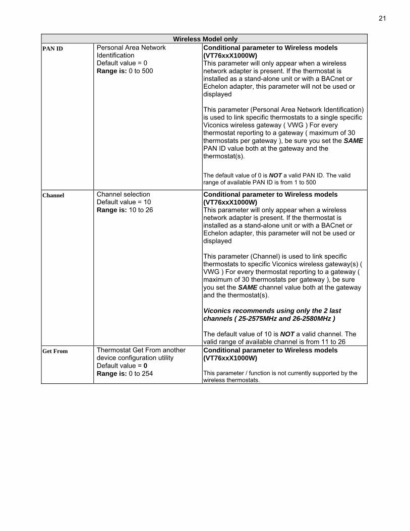
Wireless Model only PAN ID Personal Area Network
Identification Default value = 0 Range is: 0 to 500
Conditional parameter to Wireless models (VT76xxX1000W) This parameter will only appear when a wireless network adapter is present. If the thermostat is installed as a stand-alone unit or with a BACnet or Echelon adapter, this parameter will not be used or displayed This parameter (Personal Area Network Identification) is used to link specific thermostats to a single specific Viconics wireless gateway ( VWG ) For every thermostat reporting to a gateway ( maximum of 30 thermostats per gateway ), be sure you set the SAME PAN ID value both at the gateway and the thermostat(s).
The default value of 0 is NOT a valid PAN ID. The valid range of available PAN ID is from 1 to 500
Channel Channel selection Default value = 10 Range is: 10 to 26
Conditional parameter to Wireless models (VT76xxX1000W) This parameter will only appear when a wireless network adapter is present. If the thermostat is installed as a stand-alone unit or with a BACnet or Echelon adapter, this parameter will not be used or displayed This parameter (Channel) is used to link specific thermostats to specific Viconics wireless gateway(s) ( VWG ) For every thermostat reporting to a gateway ( maximum of 30 thermostats per gateway ), be sure you set the SAME channel value both at the gateway and the thermostat(s). Viconics recommends using only the 2 last channels ( 25-2575MHz and 26-2580MHz ) The default value of 10 is NOT a valid channel. The valid range of available channel is from 11 to 26
Get From Thermostat Get From another device configuration utility Default value = 0 Range is: 0 to 254
Conditional parameter to Wireless models (VT76xxX1000W) This parameter / function is not currently supported by the wireless thermostats.

22Troubleshooting guide All models
Symptom Possible Cause Corrective Action Absent or incorrect supply voltage
1. Check power supply voltage between C & RC to be from 19-30 Vac
2. Check for tripped fuse or circuit breaker
No display on the thermostat
Overloaded power transformer
Verify that the transformer used is powerful enough (enough VA’s) to supply all controlled devices including the thermostat
Keyboard menu does not access all functions
Keyboard locked Change configuration parameter LOCKOUT to value “0” to access all levels of the menu
Temperature setpoints revert to original value after a certain time period
Temporary setpoint option selected
1. The thermostat needs to be in Permanent setpoint mode for the new setpoint to be kept and memory and used all the time
2. Go to the Set temperature menu. 3. The last prompt is setpoint type. Set it to
Permanent setpoint
Wrong mode selected Select heating mode Thermostat in Unoccupied mode
Select Occupied Hold in Schedule hold or Override to force the thermostat Occupied heating setpoint
Anticycle delay active Wait, the anticycling period will end and the equipment will start
Heating setpoint is satisfied Raise the Heating setpoint Heating lockout attained 1. Mode is locked out based on outside air
temperature 2. Change configuration parameter H Lock to value
120 °F ( 49 °C ) to by-pass lockout
Thermostat will not call for heating
Wiring error 1. Start the Fan by forcing the Fan ON mode 2. Put a jumper across terminals RH & W1. The
heating should come ON. If it does not, verify wiring and check if a jumper is required between RC & RH
Wrong mode selected Select cooling mode Thermostat in Unoccupied mode
Select Occupied Hold in Schedule hold or Override to force the thermostat Occupied cooling setpoint
Anticycle delay active Wait, the anticycling period will end and the equipment will start
Cooling setpoint is satisfied Lower the cooling setpoint Cooling lockout attained 1. Mode is locked out based on outside air
temperature 2. Change configuration parameter C Lock to value -
40 °F ( -40 °C ) to by-pass lockout
Thermostat will not call for cooling
Wiring error 1. Start the Fan by forcing the Fan ON mode 2. Put a jumper across terminals RC & Y1. The
cooling should come ON. If it does not, verify wiring
Wrong mode selected The thermostat will not turn on the fan Wiring error
1. Start the Fan by forcing the Fan ON mode 2. Put a jumper across terminals RC & G. The fan
should come ON. If it does not, verify wiring
Digital display shows missing digits or erratic segments
Defective display Replace thermostat

23Troubleshooting guide Heatpump models
Wrong mode selected Select emergency heat mode Thermostat in Unoccupied mode
Select Occupied Hold in Schedule hold or Override to force the thermostat Occupied heating setpoint
Anticycle delay active Wait, the anticycling period will end and the equipment will start
Heating setpoint is satisfied Raise the Heating setpoint High Balance point attained 1. Mode is locked out based on outside air
temperature 2. Change configuration parameter High BP to value
90 °F ( 32 °C ) to by-pass lockout Heating lockout attained 1. Mode is locked out based on outside air
temperature 2. Change configuration parameter H Lock to value
120 °F ( 49 °C ) to by-pass lockout
Auxiliary heat does not operate
Wiring error 1. Start the Fan by forcing the Fan ON mode 2. Put a jumper across terminals RH & W1. The
heating should come ON. If it does not, verify wiring and check if a jumper is required between RC & RH
Heat pump does not operate in heating mode
Wrong mode selected Select heating mode
Thermostat in Unoccupied mode
Select Occupied Hold in Schedule hold or Override to force the thermostat Occupied heating setpoint
Anticycle delay active Wait, the anticycling period will end and the equipment will start
Heating setpoint is satisfied Raise the Heating setpoint Low Balance point attained 1. Mode is locked out based on outside air
temperature 2. Change configuration parameter Low BP to value -
12 °F ( -24 °C ) to by-pass lockout Heating lockout attained 1. Mode is locked out based on outside air
temperature 2. Change configuration parameter H Lock to value
120 °F ( 49 °C ) to by-pass lockout Wiring error 1. Start the Fan by forcing the Fan ON mode
2. Put a jumper across terminals RH & W1. The heating should come ON. If it does not, verify wiring and check if a jumper is required between RC & RH
Wrong reversing valve configuration
1. Wrong selection of parameter Re Valve 2. Select O will energize the valve in cooling
operation. Valve is normally heat. 3. Select B will energize the valve in heating
operation. Valve is normally cool.
24
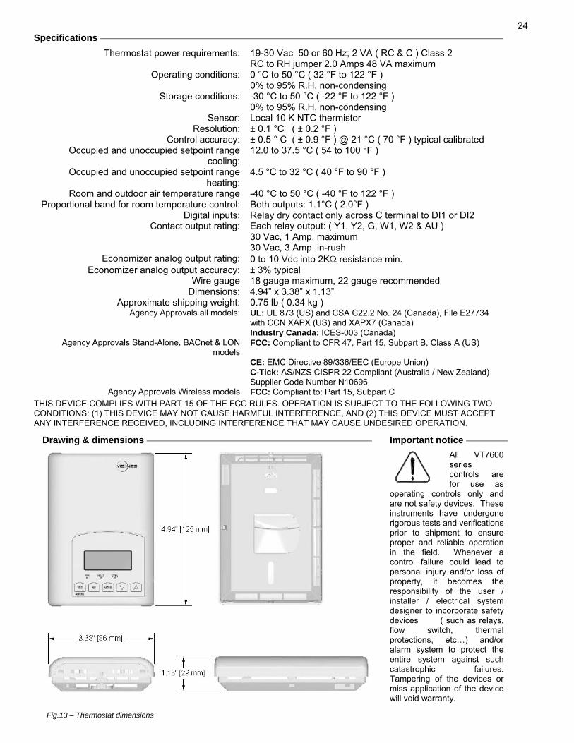
Specifications
Thermostat power requirements: 19-30 Vac 50 or 60 Hz; 2 VA ( RC & C ) Class 2 RC to RH jumper 2.0 Amps 48 VA maximum
Operating conditions: 0 °C to 50 °C ( 32 °F to 122 °F ) 0% to 95% R.H. non-condensing
Storage conditions: -30 °C to 50 °C ( -22 °F to 122 °F ) 0% to 95% R.H. non-condensing
Sensor: Local 10 K NTC thermistor Resolution: ± 0.1 °C ( ± 0.2 °F )
Control accuracy: ± 0.5 ° C ( ± 0.9 °F ) @ 21 °C ( 70 °F ) typical calibrated Occupied and unoccupied setpoint range
cooling:12.0 to 37.5 °C ( 54 to 100 °F )
Occupied and unoccupied setpoint range heating:
4.5 °C to 32 °C ( 40 °F to 90 °F )
Room and outdoor air temperature range -40 °C to 50 °C ( -40 °F to 122 °F ) Proportional band for room temperature control: Both outputs: 1.1°C ( 2.0°F )
Digital inputs: Relay dry contact only across C terminal to DI1 or DI2 Contact output rating: Each relay output: ( Y1, Y2, G, W1, W2 & AU )
30 Vac, 1 Amp. maximum 30 Vac, 3 Amp. in-rush
Economizer analog output rating: 0 to 10 Vdc into 2KΩ resistance min. Economizer analog output accuracy: ± 3% typical
Wire gauge 18 gauge maximum, 22 gauge recommended Dimensions: 4.94” x 3.38” x 1.13”
Approximate shipping weight: 0.75 lb ( 0.34 kg ) Agency Approvals all models: UL: UL 873 (US) and CSA C22.2 No. 24 (Canada), File E27734
with CCN XAPX (US) and XAPX7 (Canada) Industry Canada: ICES-003 (Canada)
Agency Approvals Stand-Alone, BACnet & LON models
FCC: Compliant to CFR 47, Part 15, Subpart B, Class A (US)
CE: EMC Directive 89/336/EEC (Europe Union) C-Tick: AS/NZS CISPR 22 Compliant (Australia / New Zealand)
Supplier Code Number N10696 Agency Approvals Wireless models FCC: Compliant to: Part 15, Subpart C
THIS DEVICE COMPLIES WITH PART 15 OF THE FCC RULES. OPERATION IS SUBJECT TO THE FOLLOWING TWO CONDITIONS: (1) THIS DEVICE MAY NOT CAUSE HARMFUL INTERFERENCE, AND (2) THIS DEVICE MUST ACCEPT ANY INTERFERENCE RECEIVED, INCLUDING INTERFERENCE THAT MAY CAUSE UNDESIRED OPERATION.
Drawing & dimensions
Important notice
All VT7600 series controls are for use as
operating controls only and are not safety devices. These instruments have undergone rigorous tests and verifications prior to shipment to ensure proper and reliable operation in the field. Whenever a control failure could lead to personal injury and/or loss of property, it becomes the responsibility of the user / installer / electrical system designer to incorporate safety devices ( such as relays, flow switch, thermal protections, etc…) and/or alarm system to protect the entire system against such catastrophic failures. Tampering of the devices or miss application of the device will void warranty.
Fig.13 – Thermostat dimensions