aviation project group 2f - barry van niekerk
TRANSCRIPT


Aviation project group 2F
Landing Gear
Index
Summary ................................................................................................................................................. 1
Introduction ............................................................................................................................................. 2
1 Function Analysis ............................................................................................................................. 3
1.1 Support .................................................................................................................................... 3
1.1.1 Landing gear layout of a 747-400 .................................................................................... 3
1.1.2 Weight distribution ......................................................................................................... 4
1.1.3 Shock absorber ................................................................................................................ 4
1.2 Manoeuvring ........................................................................................................................... 4
1.2.1 Nose gear ......................................................................................................................... 4
1.2.2 Main gear ......................................................................................................................... 5
1.3 Braking ..................................................................................................................................... 6
1.4 Folding ..................................................................................................................................... 7
1.4.1 Resistance of the aircraft ................................................................................................. 7
1.4.2 Safety due to folding ....................................................................................................... 7
1.4.3 Position nose gear ........................................................................................................... 7
1.4.4 Position main gear ........................................................................................................... 7
2 Construction analyse ....................................................................................................................... 8
2.1 Position landing gear ............................................................................................................... 8
2.1.1 Location ........................................................................................................................... 8
2.1.2 Ground clearance ............................................................................................................ 8
2.2 Nose gear ................................................................................................................................. 8
2.2.1 Parts ................................................................................................................................. 8
2.2.2 Steering ............................................................................................................................ 9
2.2.3 Anti-shimmy .................................................................................................................. 10
2.3 Main gear............................................................................................................................... 10
2.4 Gear select lock ..................................................................................................................... 11
2.4.1 Landing gear retracted lock ........................................................................................... 11
2.4.2 Landing gear down lock ................................................................................................. 11
2.5 Tires ....................................................................................................................................... 12
2.5.1 Categories ...................................................................................................................... 12
2.5.2 Construction of the tire ................................................................................................. 13
2.5.3 Hydro planning .............................................................................................................. 14
2.5.4 Reverted rubber ............................................................................................................ 14
2.6 Braking system ...................................................................................................................... 15
2.6.1 Converting kinetic energy .............................................................................................. 15

Aviation project group 2F
Landing Gear
2.6.2 Activating the braking system ....................................................................................... 15
2.6.3 Braking due to tires ....................................................................................................... 17
2.6.4 Deactivating the braking system ................................................................................... 18
3 Associated systems ........................................................................................................................ 18
3.1 Indicated systems .................................................................................................................. 18
3.1.1 Air/ground logic system ................................................................................................ 18
3.1.2 Gear position indication ................................................................................................ 18
3.1.3 Brake temperature indicators ....................................................................................... 19
3.2 Controlling systems ............................................................................................................... 19
3.2.1 Hydraulic system ........................................................................................................... 20
3.2.2 Anti-skid unit ................................................................................................................. 20
3.2.3 Auto brake ..................................................................................................................... 21
3.2.4 Parking brake ................................................................................................................. 22
3.2.5 Self-centering ................................................................................................................ 22
3.2.6 Tilt system...................................................................................................................... 22
3.3 Warning system ..................................................................................................................... 22
3.3.1 Air ground logic ............................................................................................................. 22
3.3.2 Ground proximity warning system ................................................................................ 22
3.3.3 Warning horn ................................................................................................................. 23
3.4 Conclusion ............................................................................................................................. 23
Sources .................................................................................................................................................. 24
Appendix ............................................................................................................................................... 25

Aviation project group 2F
1 Landing Gear
Summary Amsterdam Aviation Engineering has assigned group 2F of Aviation Studies to analyse the landing gear of a Boeing 747-400 to see whether this industry is worthy to be invested in or not. Therefore this analysis consists of a comprehensive study of the function, construction and operation of the landing gear called the technical analysis. Which is divided into 2 parts, “Part A” consist the functional and construction analysis, about the relations of the functions of the Boeing 747-400 and “Part B” the mechanical analysis, about the external loads of the landing gear according to the CS-25. Part B also describes three critical situations as exemplified by the static load and shows which parts have the greatest loads. The landing gear is a crucial structure that consists of a main gear assembly and a nose gear assembly that supports the aircraft on the ground. This support structure allows the aircraft to manoeuvre itself over the ground during taxiing, take-off and landing. Once the aircraft has taken off the landing gear is retracted into the fuselage to decrease the resistance and the retraction is also crucial for the safety. To stop the aircraft, its kinetic energy has to be converted by brakes into thermal energy via friction. All these functions are possible due to the construction of the landing gear that has to withstand the forces they have to endure. All the gear its assemblies are suited; with wheels on the bogeys to roll over the ground and a shock strut to balance the upward force by damping the vertical oscillations. The construction of the nose gear is able to steer with their double-wheel bogie but not to brake unlike the main gear. The main gear exists out of a body gear and a wing gear. Each of them has two four-wheel bogies with braking gear units. These braking gear units consist of rotors and stators which are squeezed against each other when they decelerate the aircraft. The performances of these functions are based on the air/ground logic system that registers whether the aircraft is airborne or on the ground. This information is extensively showed in the cockpit by indicating systems that indicate the position of the gears and the status of the brake temperature. To ensure a safe and effective use of the landing gear there are control systems. The controlling systems provide guidance and adjustments of the landing gear by making use of hydraulic systems, anti-skid units, differential brake systems and a tilt system to retract the gear assemblies. If a problem occurs with any of these systems the pilots are informed by warning/safety systems that indicate what the problems are and where the problems occurred. Based on the analysis of the landing gear of the Boeing 747-400 it has become clear how essential the landing gear is of an aircraft. It is a complex construction that is controlled by many systems that allow an aircraft to perform at their best.

Aviation project group 2F
2 Landing Gear
Introduction Amsterdam Aviation Engineering AAE is a supplier of high technique parts for aviation industry. The direction of AAE wants to expand the number of products. Therefore the direction has gathered project group 2F to make a technical analysis of a landing gear. The direction wants to know whether it is useful to investigate in landing gears. This will be tested by written test procedures for certification of CS-25. Project group 2F consists of eight people. All of the eight people are second years Aviation Studies students. The group will be led by a project supervisor who will guide the group on their work and will ensure them for improvement of this functional analyse. This functional analysis “Part A” is divided into three chapters. First the functions of the landing gear of the Boeing 747-400 (the chosen airliner) are given (1). Hereby a clear description is given of the landing gear. The first function that is described is support. The second function of the landing gear is enabling the aircraft to manoeuvre. As third function of the landing gear the braking is described. Also the landing gear must fold. This should be done for security reasons and the aircraft will be more streamlined. In the second chapter (2) the construction of the landing gear is described because this part of the function analyses has AAE’s interest. In the beginning is made clear why the landing gear has a determined position. Further the construction of the nose gear, main gear and the main parts of the landing gear will be described. Just as the braking system which converts the kinetic energy into thermal energy. In the last chapter (3) the operation of the landing gear will be discussed. This is described because a good operation of the landing gear can be achieved using associated systems. These systems consist of: indicating systems, controlling system and warning systems plus safety systems. The indicating systems provide indications of the status of the aircraft. The controlling systems provide guidance and adjustment. The warning systems provide the pilots information so that the pilots can ensure a safe flight. These systems indicate the pilot and computers of any problems in flight or on ground. The mechanical analysis will be described in “Part B” of the technical analysis. The common sources that are used the most are the, ATPL book (2011) and the document Boeing 747-400 Aircraft Manual (2009). Further the appendixes can be found at the end of the report. The appendixes consist of main figures and data.

Aviation project group 2F
3 Landing Gear
1 Function Analysis ‘Landing gear’ is not the best name for the system because the landing gear is not only used for landing. Another purpose for the landing gear is to support (1.1) the aircraft. Besides that the landing gear is also used to manoeuvre (1.2) the aircraft on the ground to and from the gate. Another task of the landing gear is to slow down the aircraft during landing or during a rejected take-off with other words, braking (1.3). At last the landing gear has to be fold up (1.4) after taking-off and during flight to minimalize the drag of the airplane to save fuel, but especially for the safety of the landing gear so it will not be damaged.
1.1 Support The main purpose of the landing gear is to support the plane’s weight. The 747-400 uses a tricycle layout where the main gear supports 90% of its weight. This layout (1.1.1) has several advantages over a conventional gear. The large kinetic energy that occurs with landing can damage the runway if the forces are not distributed well. This distribution can be done by a larger amount of wheels. This lowers the aircraft classification number whereby the aircraft could land at less stronger runways (1.1.2). The high kinetic energy during touch down could also damage the aircraft and will not give a comfortable ride while taxiing. Therefore a plane consists of a spring which converts the kinetic energy. Unfortunately the spring causes vertical oscillations. These oscillations have to be damped with a damper. There are variations of springs and dampers. The 747-400 uses an oleo-strut which works on gas and oil (1.1.3). 1.1.1 Landing gear layout of a 747-400 The landing gear of a 747 is arranged in a sort of tricycle layout (Figure 1). This contains of a nose
gear (1) and a main gear around the centre of gravity. The main gear consists of the body gear (2)
and the wing gear (3). The main gear will support 90% of the plane’s weight. This arrangement of
wheels in comparison with a conventional gear, with a tail wheel instead of a nose wheel, gives the
pilot a good visibility on ground. A conventional gear is also more vulnerable to ground loop. Ground
loop is a rapid rotation of an aircraft on ground caused by aerodynamic forces. Due the negative
angle of attack of a tricycle gear the plane is easier to handle on the ground. Conventional aircrafts
have on the ground a positive angle of attack and with rough winds it could generate lift at one of the
wings. This makes it harder to handle on ground because there is not enough weight on the landing
gear for braking and steering.
Figure 1 : Positioning landing gear Boeing 747
Aviation project group 2F
4 Landing Gear
1.1.2 Weight distribution The main gear of a 747-400 consists of 16 wheels. These wheels are divided over four trucks, also called four wheel bogies, which support the plane’s weight by a point load. The amount of wheels gives the aircraft a low and good aircraft classification number. The aircraft classification number (ACN) is a dimensionless number and indicates the effect of an airplane landing on a runway. The more wheels the more forces are distributed. Otherwise the runway will be harmed under the high amount of kinetic energy due a too low distribution. This number is connected with the pavement classification number (PCN). This number represents the strength of the pavement of the runway. The PCN also exists of a dimensionless number. When the ACN of an aircraft is lower or equal to the PCN of a runway aircraft can land on that runway unrestricted. 1.1.3 Shock absorber The aircraft needs a system that handles the high amount of kinetic energy during the touchdown and a rejected take off. The aircraft needs also a system that handles the oscillation that can appear while taxiing, otherwise heavy oscillations can cause heavy peak loads what could damage the aircraft structure. Therefore forces need to be conversed. A way to convert those forces is to make use of a spring. A spring converses kinetic energy into a power stroke. The kinetic energy forces the spring to compress. The more the spring compresses the more opposite normal stress will occur. Eventually the normal stress is bigger than the compressive stress and begins to push back the spring to its original form. A negative phenomenon what will happen is vertical harmonic oscillation. This happens because when the spring will spring back it will override its equilibrium causing the spring again to spring back and so on. To stop these oscillations the spring has to be damped. Damping converts the kinetic energy into thermal energy. Eventually the spring returns to its equilibrium. By preventing those oscillations the aircraft will not bounce over the runway. In other words the aircraft keeps good surface contact. Surface contact is of great significance when it comes to braking. The kinetic energy during the support of the aircraft and during the take-off and landing of the aircraft can be absorbed by different types of struts. The kind of shock absorber used on the Boeing 747-400 is the oleo-pneumatic strut. There are a variety of different shock absorbers of this kind but the most basic strut exists of a cylinder filled with nitrogen and oil.
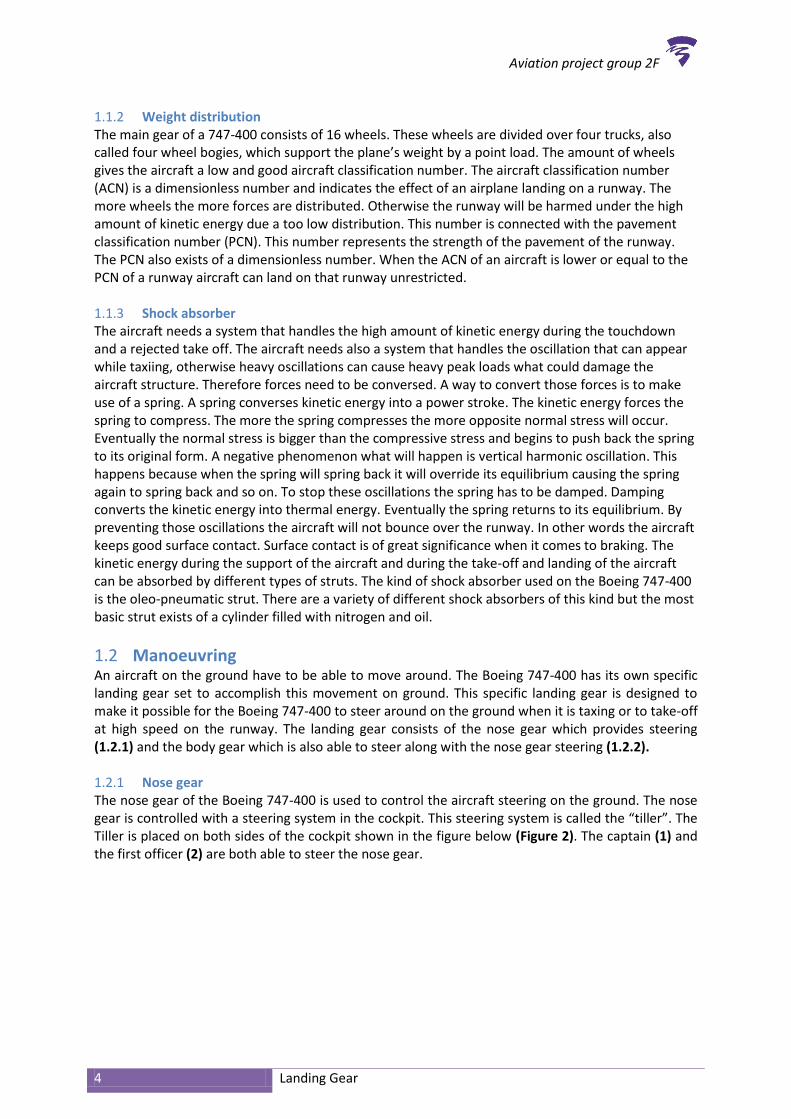
1.2 Manoeuvring An aircraft on the ground have to be able to move around. The Boeing 747-400 has its own specific landing gear set to accomplish this movement on ground. This specific landing gear is designed to make it possible for the Boeing 747-400 to steer around on the ground when it is taxing or to take-off at high speed on the runway. The landing gear consists of the nose gear which provides steering (1.2.1) and the body gear which is also able to steer along with the nose gear steering (1.2.2). 1.2.1 Nose gear The nose gear of the Boeing 747-400 is used to control the aircraft steering on the ground. The nose gear is controlled with a steering system in the cockpit. This steering system is called the “tiller”. The Tiller is placed on both sides of the cockpit shown in the figure below (Figure 2). The captain (1) and the first officer (2) are both able to steer the nose gear.
Aviation project group 2F
5 Landing Gear
Figure 2: Boeing 747 Tiller
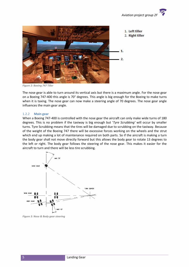
The nose gear is able to turn around its vertical axis but there is a maximum angle. For the nose gear on a Boeing 747-400 this angle is 70° degrees. This angle is big enough for the Boeing to make turns when it is taxing. The nose gear can now make a steering angle of 70 degrees. The nose gear angle influences the main gear angle. 1.2.2 Main gear When a Boeing 747-400 is controlled with the nose gear the aircraft can only make wide turns of 180 degrees. This is no problem if the taxiway is big enough but ‘Tyre Scrubbing’ will occur by smaller turns. Tyre Scrubbing means that the tires will be damaged due to scrubbing on the taxiway. Because of the weight of the Boeing 747 there will be excessive forces working on the wheels and the strut which end up making a lot of maintenance required on both parts. So if the aircraft is making a turn the body gear shall not move directly forward but this allows the body gear to rotate 13 degrees to the left or right. The body gear follows the steering of the nose gear. This makes it easier for the aircraft to turn and there will be less tire scrubbing.
Figure 3: Nose & Body gear steering

Aviation project group 2F
6 Landing Gear
1.3 Braking When a Boeing 747-400 gains velocity it also gains kinetic energy (Equation 1). Brakes are needed to decelerate the aircraft. The purpose of braking is to convert kinetic energy into thermal energy, via friction and dissipate some of the heat to the atmosphere. Therefore the energy required to stop an aircraft is equal to the kinetic energy of the aircraft; a function of the mass of the aircraft multiplied by the square of its speed multiplied with a half.
Kinetic energy
With:
Equation 1: Kinetic energy
The conversion of the kinetic energy into thermal energy for the Boeing 747-400 is for 80% carried out by the brake units. Also when the tires touch the surface, a little of the kinetic energy will already be converted into thermal energy by the acceleration of the wheels. For both situations the kinetic energy will be converted via friction, because in both situations there is a moving part and a stationary part which rub against each other. The amount of friction is depending on the type of material. Therefore a part of the brake equation consists of friction coefficient. The other term of the brake equation is depending on the braking pressure (Equation 2). Assumed is that using the law of Bernoulli the volume remains the same so the area will also remain the same. Therefore the area is not present by the equation of Brake force.
Brake force With: (Assumed 0,4 in good conditions)
Equation 2: Brake force
A Boeing 747-400 has different kind of brakes. Each main gear wheel has a multiple disc carbon brake. The nose wheels have no brakes because the nose gear is not build for the brake forces. The brake system includes:
Normal brake hydraulic system This is a hydraulic system which connects the brake pedals with the multiple disc brakes (Appendix VI: Normal brake system diagram). The brake pedals provide independent control of the left and right brakes.
Alternate/reserve brake hydraulic system This is a back-up hydraulic system.
Brake accumulator The brake accumulator provides for parking brake application. The brake accumulator provides sufficient pressure to set and hold the parking brakes when all other sources of brake pressure fail.
Antiskid protection

Aviation project group 2F
7 Landing Gear
The antiskid system prevents the aircraft from skid. This is done by sensors which are mounted on each wheel. Those sensors measure the wheel rotation speed. The most effective way of braking is with a wheel speed that is around 85 to 90% of the ground speed. When the wheel speed is much lower than the ground speed the antiskid system will release the brake at that certain wheel.
Auto brake system The auto brake system provides braking at preselected deceleration rates for landing and full pressure for rejected take-off. The system operates only when the normal brake system is functioning. The automatic braking system will operate when the wheel speed increases to 60kts or more during touchdown. A selector makes it possible to allow five deceleration levels and a rejected take-off mode.
Parking brake
1.4 Folding The folding of the landing gear is necessary in order to ensure that the procedure of the flight can be performed safely after taking off. Folding of the landing gear (Appendix I: Wheel well doors of 747-400) will have a significant impact on the resistance of the aircraft (1.4.1). Besides the impact on the resistance the landing gear also folds out of precaution so that the remainder of the flight and the landing of the aircraft will not be damaged (1.4.2) and the flight can be performed safely. To retract the landing gear there has to be a storage place inside the fuselage of the aircraft intended for the nose gear (1.4.3) and one for the main gear (1.4.4). 1.4.1 Resistance of the aircraft The resistance of an aircraft is based on the shape of the model. By making the shape of an aircraft more streamlined it has to suffer less resistance. Therefore as an aircraft takes off it is important to retract the landing gear to streamline the fuselage. The benefit of reducing the resistance is saving fuel as there will not be as much fuel needed during a flight with folded landing gear compared to a situation where the landing gear cannot be retracted. This means that when the landing gear is folded in the aircraft is environmentally better too. 1.4.2 Safety due to folding The retraction of the landing gear is not only beneficial for a better streamlined aircraft but also for safety. When the landing gear is not retracted it is possible that the landing gear will be damaged during touchdown by ice build-ups and bird strikes. According to the limitations of the landing gear an aircraft may not fly long in icing condition with gear down. Hereby the materials of the landing gear, including the brakes, can freeze. So therefore it is possible that the brakes will not work during the landing. It is essential that the wheel well doors are closed during flight. Otherwise there will be a huge area where snow and birds can gather. 1.4.3 Position nose gear The Boeing 747-400 has two wheels in front of the hull that can be retracted (Appendix I: Wheel well doors of 747-400). These two wheels form the nose gear. As the nose gear is retracted into the fuselage of the aircraft it is stowed at the wheel well. This area is locked down by two wheel well doors. These wheel well doors ensure the streamline of the shape of the aircraft as the nose gear is folded during a flight. 1.4.4 Position main gear The Boeing 747-400 has also another part of the landing gear called the main gear (Appendix I: Wheel well doors of 747-400). The main gear is mounted behind the centre of gravity of the aircraft. This is essential otherwise the aircraft would not be able to stand on his wheels but it would fall on

Aviation project group 2F
8 Landing Gear
his tail. The main gear is also retracted into the fuselage of the aircraft and it is stowed at the wheel well. The wing gear and body gear stowed behind eight wheel well doors.
2 Construction analyse The structure of the landing gear of the Boeing 747 must be able to withstand forces. The landing gear must handle the forces so the position (2.1) has to be aligned with the centre of gravity. For the nose gear (2.2) a special construction is made to let it extent and retract while making the gear able to steer around its vertical axis. The main gear (2.3) is made to withstand the certified forces. The structure of the body gear must be able to steer as well. When the landing gear is down or retracted it has to be locked (2.4). The wheels and tires (2.5) are made from specific materials for longevity. Landing at speeds around 130-160 knots is normal for a Boeing 747-400. To de-accelerate this large aircraft it needs brakes and braking systems (2.6).
2.1 Position landing gear The position of the landing gear is essential. Most forces act on the main gear therefore this must be balanced with the centre of gravity. The location (2.1.1) of the landing gear on the 747-400 is determined so that the aircraft is fully stabile. An aircraft lands with a pitch angle on the runway. At this angle the tail may not touch the ground. This is called ground clearance (2.1.2). 2.1.1 Location The nose gear of the Boeing 747-400 is placed under the nose of the aircraft. This is to provide stability because the centre of gravity may now lie between the nose and the wings. For the Boeing 747-400 the centre of gravity is more close to the wings. This makes the aircraft highly stable on ground. The placement of the gear is shown in the next figure (Appendix II: Dimensions Gear). Shown is the nose gear which is placed 25 feet from the nose of the aircraft. Also the dimensions of the body gear and the wing gear are shown. More dimensions of the Boeing 747-400 can be found in the: (Appendix IV: Dimensions 747) 2.1.2 Ground clearance The main landing gear is placed in such way that during rotation the tail of the aircraft does not come into contact with the ground. The aircraft must be able to achieve ninety per cent of the critical angle of attack without tail strike. The amount of ground clearance for the aircraft can be obtained from the appendix (Appendix V: Ground clearance).
2.2 Nose gear The construction of the nose gear must be strong. It is therefore important to know the whole structure of the nose gear. The parts (2.2.1) used in the nose gear are linked together so it makes a whole complex gear with several parts that work together so that landing gear can function. For the nose gear to steer (2.2.2) some special hydraulic and turn able parts are used. After all the nose gear runs on two tyres. This is to counter the shimmy (2.2.3) effect. 2.2.1 Parts The nose gear of a Boeing 747-400 consists of a lot of different parts. Looking at all the parts of the nose gear makes it easier to determine what they do and whether they take part in strong force moments. The nose gear of the B747-400 is shown beneath in the picture (Figure 4). Arguably the most import parts of the landing gear are the wheels and tyres (1) as they serve as the point of contact between the aircraft and the ground. The wheels’ rotation is provided by an axle (2) which is attached to the shock strut’s inner cylinder (3). The inner cylinder is inserted into the outer cylinder (4). The Inner and outer cylinders are held together by the lower (5) and upper (6) torsion links. On the outer cylinder the torsion link is attached to the forward (7) and aft (8) steering collar, which can

Aviation project group 2F
9 Landing Gear
rotate around the cylinder. The rotation of the collar is controlled by the steering actuators (9) which are fixed to the outer cylinder. This combination of torsion link and steering collar means that the inner cylinder can only rotate inside the outer cylinder when a steering input is made, preventing undesired rotations due to external forces. To strengthen the nose gear the outer cylinder is supported by two side braces (10) and the lower tripod brace (11). The cylinder and the side braces are attached to the aircraft itself by the trunnion fittings (12). The trunnion fitting can absorb forces in y and z direction. The trunnion fittings are hinged imposed in y direction and fixed imposed in x and z direction. It is hinged imposed in y direction to allow the whole nose gear to rotate forward into the fuselage during retraction. The torque required for this rotation is provided by the nose gear actuator (13). The lower tripod brace is also connected to the trunnion via the upper tripod brace (14). The drag strut (15) absorbs longitudinal forces on the gear (mainly caused by air and ground friction). The drag strut contains a locking mechanism to secure the gear in the up or down position. This lock is operated by a hydraulic actuator (16). This, four bars linked construction, will go forward by an extraction of the nose gear. If the nose gear retraction construction does not work the gear has an alternate extension method by free fall.
Figure 4: Nose gear parts Boeing 747
2.2.2 Steering The maximum steering angle that a pilot can make with the nose wheel is 70 degrees this can be realized with the tiller. A tiller movement of 140 degrees results in a steering motion of 70 degrees. The steering construction is illustrated in the top view of part A of (Figure 4), as can be seen in (Figure 5). Tiller movement is transmitted via cables to a control metering valve (1). From the metering valve there will be forces passed on to the wheel steering actuator (2) through the hydraulic system. Then the steering actuator will be activated and the forces will pass to the attach pin (3) in both directions. Through these pins a torque reaches the forward steering collar (4). The torque will wind up with the upper torsion link, which is linked with lower torsion link. The upper torsion link sends the inner cylinder to the left or right. The cylinder controls the axis of the wheels and this will result in a turning motion.

Aviation project group 2F
10 Landing Gear
Figure 5: Top view Nose gear part
In addition to the normal control there is also another way to steer the nose wheels. Namely with the help of the rudder pedals, which are connected to the nose wheel steering system. The pilot can control the aircraft in this way only if the weight of the aircraft presses on the nose gear. This way the nose gear can make an angle of about 10 degrees. 2.2.3 Anti-shimmy The flexibility of the side walls of the tires give vibrations, also known as shimmy, in the nose-wheel. Especially at high speeds the shimmy of the nose wheel can cause many vibrations to the entire aircraft. This does not only wear on the nose wheel but is also very dangerous because the vibrations can damage the aircraft. Shimmy can be caused by wear on the nose wheel bearings, worn shimmy dampers, worn tires spring washers and uneven tire pressure. To counter the Shimmy there are some Anti-Shimmy solutions:
Twin contact wheels (wheels with two contacts on the surface) Shimmy damper (Light aircraft - friction damper, large aircraft - Hydraulic dampers) Mounting heavy self-centring springs Double nose wheels
The Boeing 747 uses dual nose wheels so that it has an anti-shimmy function. Because of the weight of the aircraft the surface of these two wheels are also needed for the support of the aircraft and it is possible to land with one flat tire on the Nose Gear.
2.3 Main gear Normally an aircraft has three landing gear units, but the Boeing 747 can carry more weight by dividing the forces over the extra landing gear units. As earlier is told in (1.1.1) Landing gear Layout the main gear of the Boeing 747 consist out of the wing gear and the body gear, this is illustrated in (Appendix II: Dimensions Gear). The wing gear has two landing gear units on the outside, which are placed underneath the rear wing. The body gear has two landing gear units in the middle, which are slightly after the wing gear. The body gear is attached to the fuselage. The Boeing 747 has a bicycle-type landing gear; this landing gear consists of parts and assemblies. The main gear of the Boeing 747 (Figure 6) is attached to the air frame by trunnion fittings (1). These trunnion fittings are hinges that allow the landing gear to rotate around the longitudinal axis, as is described in (2.2). The trunnion fittings are attached to the shock strut (2). The shock strut is an oleo-pneumatic system or oil-air hydraulic. It contains of an inner and outer cylinder which uses nitrogen and oil. The nitrogen supports the weight when the airplane is stationary on ground. During landing

Aviation project group 2F
11 Landing Gear
or taxiing, the nitrogen in the strut gets compressed and starts to vertically oscillate. The oil will then absorb these oscillations. The inner cylinder which is attached to the wheel can move up- and downwards into the outer cylinder to decrease the force on the aircraft by damping the vertical oscillations. The outer cylinder is attached to the airframe. There are also other objects in the construction that support the aircraft and these objects are the torque links (3). With the torque links it is possible to put the landing gear in an oblique position to improve the landing position. Underneath the torque links there is a jointly and sprung truck/bogie beam (4) that connects the axle (5), a central shaft to the wheels and tires (6) that are attached to allow the movement of the aircraft. The movement of the aircraft is stopped by the wheel brakes (7). The construction of the landing gear should also be able to be retracted. Therefore there is a retract cylinder (8) incorporated into the construction. This retract cylinder is attached to a fixed brace (9), a side brace (10), a drag brace (11) and down lock links (12). The forces on the side brace work on the lateral axis and the forces on the drag brace work on the longitudinal axis. The combination of this construction allows the landing gear to stay steady in downward position, so it won’t fold in (over centred). The main gear door (13) and the strut door (14) are the parts of the construction that seal the body.
Figure 6: Main gear
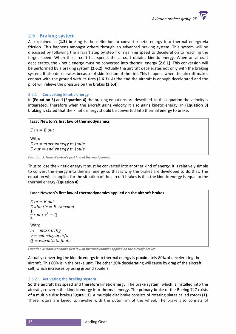
2.4 Gear select lock When the landing gear is retracted it musts stay in position and therefore it will be locked (2.4.1). The same applies if the landing gear is down (2.4.2). 2.4.1 Landing gear retracted lock To keep the gear behind the wheel well doors, the 747 makes use of a locking mechanism. The gear is locked with the use of a hook around the locking wheel, which is connected to the strut. This hook can be held in position by a spring and is controlled by the hydraulic system or with an electric actuator. How the nose- and main landing gear is folded in the aircraft is illustrated in (Appendix III: Retracted uplocks). 2.4.2 Landing gear down lock Not only if the landing gear is retracted, but also if the landing gear is down, must the gear be locked. The lock down mechanism that has to lock the gear into place mechanical, makes sure it is able to land on its gear when the hydraulic systems are malfunctioned. The lock mechanism (Figure 7) is the jury strut also known as side brace. It has an unlocked position which is used in the transit of the
Aviation project group 2F
12 Landing Gear
landing gear. When the landing gear is down the construction goes to an over centre position. This is the mechanical limit where the construction is locked. With the over centred position the forces work at the construction (X axis) so there are no forces that work on the jury strut or side brace (Y axis).
Figure 7: Mechanical Lock
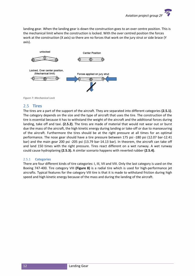
2.5 Tires The tires are a part of the support of the aircraft. They are separated into different categories (2.5.1). The category depends on the size and the type of aircraft that uses the tire. The construction of the tire is essential because it has to withstand the weight of the aircraft and the additional forces during landing, take off and taxi. (2.5.2). The tires are made of material that would not wear out or burst due the mass of the aircraft, the high kinetic energy during landing or take-off or due to manoeuvring of the aircraft. Furthermore the tires should be at the right pressure at all times for an optimal performance. The nose gear should have a tire pressure between 175 psi -180 psi (12.07 bar-12.41 bar) and the main gear 200 psi -205 psi (13.79 bar-14.13 bar). In theorem, the aircraft can take off and land 150 times with the right pressure. Tires react different on a wet runway. A wet runway could cause hydroplaning (2.5.3). A similar scenario happens with reverted rubber (2.5.4). 2.5.1 Categories There are four different kinds of tire categories: I, III, VII and VIII. Only the last category is used on the Boeing 747-400. Tire category VIII (Figure 8) is a radial tire which is used for high-performance jet aircrafts. Typical features for the category VIII tire is that it is made to withstand friction during high speed and high kinetic energy because of the mass and during the landing of the aircraft.

Aviation project group 2F
13 Landing Gear
Figure 9: Tire frame
Figure 8: Structure
2.5.2 Construction of the tire An aircraft tire should be made of the right material, so it would withstand high amount of forces during landing and rejected take-off. Typical for an aircraft tire is that it is flexible, so it would not crack because of the high kinetic energy during landing or when manoeuvring through the bends of the runway. Because of the flexibility of the tire, the tire has more surfaces and so on more contact with the ground. So the aircraft can decelerate better. To achieve this, the tire should be made of the right material and with the right layers. There are a few main components that are necessary for an aircraft tire (Figure 9) such as:
1. Bead 2. Carcass plies 3. Tried 4. Side wall
Ad 1. Bead
Tire beads are made of high strength carbon steel wire that anchors the tire carcass and provides a dimensioned, firm mounting surface for the tire on the wheel rim. The amount of beads each side of the tire depends on the size and the load of the aircraft. Another function of the tire bead is to make the tire fit against the flange of the wheel rim. Also the bead transfers the impact load and deflection forces to the wheel rim. The wheel rim is the outer edge of the wheel, holding the tire. Ad 2. Carcass plies
Carcass plies are layers of nylon, sandwiched between two layers of rubber. They are used to form the tire. The purpose of the carcass plies are to give the tire strength and form the carcass body of the tire. The carcass plies are applied in layers. Each layer is wrapped around the bead on both sides of the tire to anchor it.

Aviation project group 2F
14 Landing Gear
Ad 3. Tread
The tread is the part of the tire that makes contact with the ground. Because of that it has to be made of a type of rubber that could resist wear, abrasion, cutting and cracking. The main reason why it should be rubber is that it is flexible. It should also be able to resist heat because of the friction with the ground that is developed during movement. Also most of the tire tread have grooves in it to provide the tire with more adhesion to the ground surface. The grooves are also designed to provide cooling. The more surface the more thermal energy absorbed by the atmosphere. There are different kinds of tire treads designed for different kind of applications. The most common tire treads are shown in the figure below (Figure 10). The most common tire tread is a rub tread (1) designed for paved surfaces. The tire tread designed for unpaved runways has a diamond shape pattern (2). The rub and diamond shape pattern together makes an all-weather tread (3). The last tire tread that is shown in the figure is a smooth tire tread (4) mostly seen on older, slow aircrafts without brakes. This tire designed to brake this kind of aircrafts.
Figure 10: different kind of tire tread
Ad 4. Side walls
The side walls of the tires are also made of rubber and are designed to protect the carcass plies. The side walls of the area have less chance to be damaged. So it is the best place for the information about the tire, information about what sort of tire it is and the dimensions. The side of the tire also consists of a rubber liner adhered to the inner surface. This liner prevents the tube from chafing on the carcass plies. Tubeless tires are designed a bit different; those tires have a thicker, less permeable rubber. This thicker rubber replaces the tube and contains the nitrogen or inflation air within the tire and keeps form seeping through the carcass plies. On the lower sidewall of the tire are vent holes placed, small amounts of nitrogen, or air seep through the liner into the carcass plies. If the gas is trapped between the plies it could expand when the temperature rises and causes vulnerable spots that can cause lethal situation. To prevent this, seeping holes are made. Those holes are marked with a dot of paint, most times yellow, green or white. Tube-type tires do also have this system to allow air trapped between the tube and the tire to escape 2.5.3 Hydro planning Hydroplaning is caused by a layer of water lying on the runway. The layer of water between the runway and the tire causes for a loss of traction. The effect of the loss of traction could prevent the aircraft from reacting to steering inputs. If this phenomenon occurs to all the wheels, the aircraft could become unmanageable. The water on the runway works as a sort of lubricant (Appendix IX: Hydroplaning). 2.5.4 Reverted rubber Reverted rubber is comparable with hydroplaning that occurs when an aircraft is breaking so heavily that it results in a prolonged locked-wheel skid. The skidding tires generate plenty of heat to evaporate the water into a steamy cloud. At this point, the tires are skidding over the runway which revert the rubber to its original uncured state.
Aviation project group 2F
15 Landing Gear
2.6 Braking system As explained in (1.3) braking is the definition to convert kinetic energy into thermal energy via friction. This happens amongst others through an advanced braking system. This system will be discussed by following the aircraft step by step from gaining speed to deceleration to reaching the target speed. When the aircraft has speed, the aircraft obtains kinetic energy. When an aircraft decelerates, the kinetic energy must be converted into thermal energy (2.6.1). This conversion will be performed by a braking system (2.6.2). Actually the aircraft decelerates not only with the braking system. It also decelerates because of skin friction of the tire. This happens when the aircraft makes contact with the ground with its tires (2.6.3). At the end the aircraft is enough decelerated and the pilot will relieve the pressure on the brakes (2.6.4).
2.6.1 Converting kinetic energy In (Equation 3) and (Equation 4) the braking equations are described. In this equation the velocity is integrated. Therefore when the aircraft gains velocity it also gains kinetic energy. In (Equation 3) braking is stated that the kinetic energy should be converted into thermal energy to brake.
Isaac Newton’s first law of thermodynamics
With:
Equation 3: Isaac Newton’s first law of thermodynamics
Thus to lose the kinetic energy it must be converted into another kind of energy. It is relatively simple to convert the energy into thermal energy so that is why the brakes are developed to do that. The equation which applies for the situation of the aircraft brakes is that the kinetic energy is equal to the thermal energy (Equation 4).
Isaac Newton’s first law of thermodynamics applied on the aircraft brakes
With:
Equation 4: Isaac Newton’s first law of thermodynamics applied on the aircraft brakes
Actually converting the kinetic energy into thermal energy is proximately 80% of decelerating the aircraft. This 80% is in the brake unit. The other 20% decelerating will cause by drag of the aircraft self, which increases by using ground spoilers. 2.6.2 Activating the braking system So the aircraft has speed and therefore kinetic energy. The brake system, which is installed into the aircraft, converts the kinetic energy into thermal energy. The primary brake of the Boeing 747 exists of a multiple disc brake (Figure 11). A multiple disc brake consists of rotating plates called rotors (1). These rotors are keyed to revolve with the outer rim of the wheel. The brake also consists of

Aviation project group 2F
16 Landing Gear
stationary plates carrying the friction material called stators (2). They are keyed to remain stationary with the hub of the wheel. The brake consist further of pistons (3), a torque plate (4) and a thrust plate (5). When the brake is applied hydraulic pressure pushes the actuating pistons, which are situated into the torque plate, squeezing the rotors and stators between the pressure plate and the thrust plate. As described in 1.3 Braking occurs, the real energy conversion due to shear stress (Equation 2: Brake force). Because of the pressure of the pressure plate and the thrust plate, the rotors are rubbing against the stators. The stators are made of inorganic material which causes a lot of friction. So when the rotors rub against the stators, the rotors want to move on as well as the stators try to decelerate the rotors. The force of pressure of the pressure plate and the thrust plate are perpendicular to the rotors and stators. The friction material of the stators has a friction coefficient and as described in equation (Equation 2: Brake force) brake force is created. The harder the brake pedal is pressed, the greater the braking result will be. This is an advantage of disc brakes because then the braking force is easy to dose. A disadvantage of disc brakes is that a lot of pressure is needed to actually decelerate the rotors. Therefore the multiple disc brakes are driven by a hydraulic system. If the pilot presses the brake pedal to hard, the carbon brakes can break. At this moment the ability to slow down the aircraft decreases. In (Appendix VI: Normal brake system diagram) is illustrated how the pedals are linked with the whole brake system.

Aviation project group 2F
17 Landing Gear
Figure 11: A typical multiple disc brake unit
In chapter (2.6.2) is described that the kinetic energy is converted into thermal energy. This thermal energy is mostly absorbed by the disc brakes. A little of the thermal energy is absorbed by air molecules because of the braking due to spoilers. How much energy the disc brake absorbs depends mostly on two factors:
1. The area 2. The type of material of the disc brakes
Ad 1. The area
The larger the area of the disc brakes, the more heat it can absorb. The disc brakes must have a large enough area to absorb the thermal energy obtained during braking. On the other hand the disc brakes area must not be too large because of the mass which provide extra fuel consume. This consideration must be made when the disc brakes are designed. Ad 2. The type of material of the disc brakes
Different types of material have different types of thermal capacity. Most of the disc brakes these days are made of steel of carbon. Brakes of carbon have the advantage of weight saving but the disadvantage of high costs and the carbon brakes won’t fade as metal brakes, but carbon brakes will
break more easily, because carbon is brittle. Carbon has a thermal capacity of 0,85
whereas
steel has a thermal capacity of 0,53
. Therefore carbon can absorb more thermal energy than
steel. 2.6.3 Braking due to tires Decelerating a Boeing 747 does not only happen through the braking system, but also by the occurrence of friction between the tires and the asphalt. The tires are made of rubber as described in (2.5). The friction coefficient of rubber-asphalt comprises 0.4 to 0.8. This is important for getting a grip so that no skid occurs. The braking system, which is explained in (2.6), only works when the tires have grip. If the tires have no grip and begin to slip, the brake system will fail because the tires have no further possibility to slow down. The wheels slow down because of the friction with the asphalt.
Aviation project group 2F
18 Landing Gear
Each wheel however is provided individually with antiskid protection when normal brakes are operative. When skidding is initially detected, the antiskid controller commands the respective antiskid valve to reduce brake pressure which protects the wheel from further skidding. 2.6.4 Deactivating the braking system When the pilot releases the pressure on the brake pedals, the piston will move the pressure plate away from the stators and rotor assemblies, thus allowing them to move slightly apart. The internal construction of the piston allows them to maintain a constant running clearance when the brake is off and thereby automatically compensating for brake wear. Because of the brake wear the thickness of the brake lining material is carefully monitored. Too little brake lining material on a single disc brake system may become excessively worn or grooved. On a multiple disc brake, the remaining material overheats and erodes extremely fast. If the return spring inside the adjuster assembly ceases to function, or if the unit is wrongly adjusted, then they could be the cause of a brake not releasing correctly. This is termed brake drag. Brake drag will generate a lot of heat and can be responsible for brake fade occurring sooner than it otherwise would.
3 Associated systems A lot of systems are required to let the landing gear operate correctly and safe. Those systems can be categorized into different systems such as indication systems provide indications of the status of the aircraft (3.1). The controlling systems that provide guidance and adjustment (3.2). The warning systems provide safety and alert the pilot when something goes wrong (3.3).
3.1 Indicated systems There are four important systems that indicate the status of the landing gear. The air/ground logic system (3.1.1) indicates whether the aircraft is airborne or not. Further there is the gear position indication (3.1.2) that indicates if the landing gear is locked down, in transit or locked up. The brake temperature indicator (3.1.3). 3.1.1 Air/ground logic system The criterion of whether the aircraft is airborne or not can be indicated via micro switches or proximity sensing devices. These micro switches or devices are placed on the main landing gear oleos to register the movement of the oleo strut. The position of the oleo strut will change when it is compressed by the weight of the aircraft during landing. Therefore, as an aircraft takes off there will not be any more weight upon the wheels and bogie assembly and thus it extends the oleo strut. In both cases a controlling signal will be sent to a bank or multiple relays that switch the affected circuits to the required position. 3.1.2 Gear position indication As known the landing gear can be extended or retracted, only the landing gear is not visible for the pilots, so they can not know whether the landing gear is extended or retracted. Hereby the Boeing 747 has a system that indicates whether the landing gear is locked down, in transit or locked up. This system is the gear position indication. It consists of micro switches which are placed on the up-locks and down-locks. The micro switches make or break when the locks operate, which are connected to a landing gear position indicator on the instrument panel. There is a display (Figure 12) connected to the system which indicates the status of the landing gear. If all the landing gear units have the same status then the display shows simply the status of the landing gear units (1). DOWN (green), all landing gear units are down and locked. Crosshatched (white), the landing gear units are in transit. UP (white), all landing gear units are up and locked. Empty box (white), all landing gear position indicators are inoperative. If all the landing gear units have a different status, then the display has an expanded gear position indication (2). DN (green) related landing gear unit is down and locked.

Aviation project group 2F
19 Landing Gear
Crosshatched (white), related landing gear unit is in transit. UP (white), related landing gear unit is up and locked. When all landing gear position indicators are inoperative the display shows five crosshatches (amber) (3).
Figure 12: Gear position indication
3.1.3 Brake temperature indicators The brakes of a Boeing 747 are suited with sensors that arrange to sample the temperature of the brakes of each wheel individually. These indicators are used to display the temperature of the wheels on the system control panel (Figure 13) called Engine-Indicating and Crew-Alerting System (EICAS). The brake temperature (1) is indicated on a scale from zero to nine in each wheel. As the temperature rises the number will rise as well and the colour of the indicator will change from white normal range to amber high range. With the information about the brake assemblies there is a constant knowledge of the temperatures that should not rise above a predetermined level. In case of the exceeding of the temperature it is possible for the operator to locate the brake that triggers the alarm. Besides the temperature status, the indicator also provides the control panel with information about the status of the gear doors (2). If one of the gear doors is not closed yet the display will show a crosshatch instead of closed.
Figure 13: EICAS System
3.2 Controlling systems Controlling systems provide guidance and adjustment. A hydraulic system (3.2.1) controls the brake system, an anti-skid unit (3.2.2) detects skidding wheels and adjust the brakes, the auto brake (3.2.3) controls the automatic braking, the parking brake (3.2.4) is to set the brakes, self-centring (3.2.5) of the nose gear is needed to adjust the position of the nose gear when it is retracted and a tilt system (3.2.6) is needed to set the main gear in the retract position.

Aviation project group 2F
20 Landing Gear
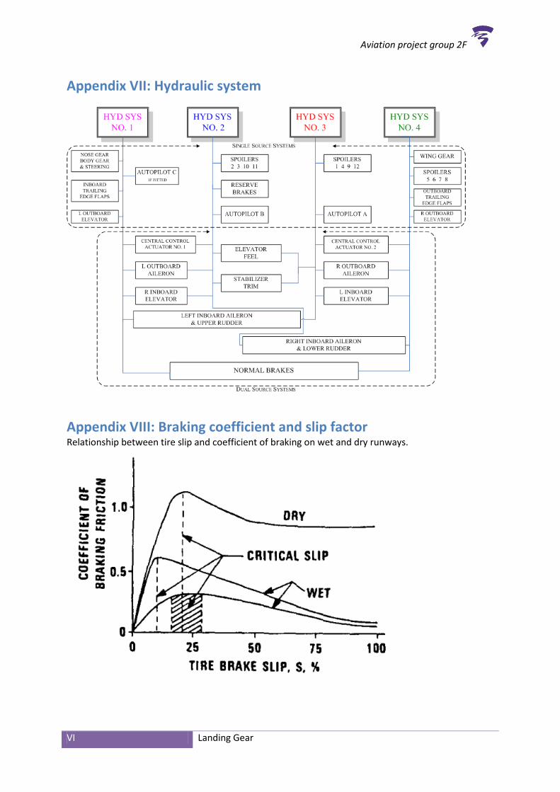
3.2.1 Hydraulic system A hydraulic system is required for controlling systems which are controlled with excessive forces. Hydraulic power is supplied by four independent systems. Each system incorporates an engine driven hydraulic pump and an air driven hydraulic pump. The pumps reservoir and associated components are located at the engine and nacelle area. This is a housing, which separated from the fuselage that holds engines, fuel or equipment in an aircraft. An electric driven hydraulic pump in system 4 is provided primarily for operation of the brake system during ground operations. Hydraulic power is utilized for the operation of the flight control system including the trailing edge flaps, stabilizer and the landing gear system including braking and steering. Normal power for landing gear extension and retraction is supplied by two independent hydraulic sources: Hydraulic system 1 for the nose and body gear and system 4 for the wing gear (Appendix VII: Hydraulic system). The alternate extension system uses electric motors to unlock the doors of the landing gear. Landing gear weight and air loading extend the gear to the locked position. Manual extension is also provided for the nose gear. Landing gear doors require hydraulic power to close after being opened. During initial retraction, automatic braking is applied to the main gear wheels. 3.2.2 Anti-skid unit When an aircraft lands on the runway the wheels will spin heavily. The pilot will apply the brakes. The friction between the runway and the tires is way less than the friction between the wheels and the brakes. If the pilot will not stop applying the brakes fast enough, the wheels of the landing gear will lock and the aircraft will begin to skid. A skidding wheel provides very little braking effect as described in chapter. The pilot is unable to sense when the wheel is going to skid. Therefore anti-skid protection is provided. The Boeing 747 uses an Anti-Skid Unit (A.S.U.) which provides the aircraft of touch down protection (3.2.2.a), skid prevention (3.2.2.b) and locked wheel protection (3.2.2.c). Furthermore utilizes the aircraft a torque limiter (3.2.2.d). 3.2.2.a Touch down protection
This will prevent the brakes being applied before touch down. An electronic controller monitors the wheel speed and the air/ground logic. When the aircraft touches the ground the wheels will ‘spin up’ and the air/ground logic, described in (3.1.1), notices that the aircraft is on the ground. Both will give a signal to the electronic controller and the controller will enable the pilot to use the brakes. 3.2.2.b Skid prevention
A Boeing 747-400 uses a second generation electronic anti-skid system which consists of three main elements:
1. Wheel speed sensors 2. A control box 3. Control valves
Ad 1. Wheel speed sensors
The wheel speed sensors are mounted in each wheel. Those sensors measure the wheel rotation speed or slip factor. When the wheel rotation speed becomes approximately 25% lower than the ground speed, the wheel will begin to lock and thus the anti-skid protection will release the brake at that certain wheel. The sensor does not sense the type of ground the aircraft runs on. This means that if the aircraft runs on ice and the pilot applies the braking system the anti-skid system will intervene too late which results in skidding wheels or hydroplaning when the aircraft runs on a wet runway. Ad 2. A control box
The control box receives the signal of the wheel speed sensors and determines the severity of the impending skid. Next, it sends the correcting signal to the relative control valve.

Aviation project group 2F
21 Landing Gear
Ad 3. Control valves
The control valve of the skidding wheel will receive a signal of the control box and will serve as bypass of the braking system. Through this the hydraulic pressure on the braking pistons will decrease and therefore the braking will diminish. When the normal brake hydraulic system is operating it provides each main gear wheel with individual antiskid protection following the ideal slip factor (Appendix VIII: Braking coefficient and slip factor). When the wheel speed sensor detects a skid, the associated antiskid valve reduces brake pressure until the skidding stops. When the alternate brake hydraulic system is operating it provides antiskid protection to wheel pairs rather than to individual wheels. To enable the pilot to have full control of the brakes during taxying and manoeuvring, the anti-skid system is deactivated when the aircraft has a velocity of approximately 20 miles per hour or lower.
3.2.2.c Locked wheel position
When the anti-skid protection will not provide the wheels from stop skidding, the wheel will lock. Then the locked wheel protection will release the pressure to that wheel completely until the wheel spins up again. 3.2.2.d Torque limiting
An excessive torque during braking can cause damage to the brake unit. Therefore a brake torque sensor is provided at each wheel. When excessive torque stress is detected, a signal is sent to the antiskid valve and brake pressure to that wheel is released. When the alternate brake system is used, the brake torque is still sensed on every individual wheel basis. However, the signal is sent to the alternate antiskid valve and brake pressure is released on a laterally paired wheel basis. 3.2.3 Auto brake The auto brake system provides braking at a preselected deceleration rate. The auto brake brakes with a constant deceleration which is adjusted to the aircraft speed. It also provides full pressure for rejected takeoff. The system operates only when the normal brake system is functioning. In the figure below (Figure 14) the auto brake knob of the Boeing 747 is shown. The auto brake of a Boeing 747 has five deceleration rates (1). The deceleration rates 1, 2 and 3 command 4, 5 and 6 ft/sec² deceleration with 0,2 seconds delay at the maximum control pressure of 1500, 1750 and 2000 PSI. Selection 4 and max auto command a deceleration of 7,5 and 11 ft/sec² with 0.2 seconds delay at the maximum control pressure of 2400 and 3000 PSI. The RTO (rejected take off) mode provides maximum braking but only when all thrust levers are closed and the ground speed is above 85 knots (2). When the knob is in disarm modus the auto brake is disarmed (3) and when the auto brake is in off modus the auto brake is disarmed and will also be reset(4).
Figure 14: auto brake knob
Aviation project group 2F
22 Landing Gear
During auto brake operation anti-skid protection is provided. When one of the five auto brakes is selected, the air/ground logic is in ground mode and the wheels are spinning the brakes will be automatically applied and will provide braking to a complete stop or until the auto brakes are disarmed. Protective features are installed that will automatically disarm the system when a fault exists or when the auto brakes are not operating. The auto brake system will not operate when using the alternate brake system. This alternate brake system will take over if an error occurs in the normal brake system. If hydraulic system 4 pressure is low, hydraulic system 1 supplies pressurize the brake system. If hydraulic pressure in both systems 4 and 1 are low, system 2 pressurize the brake system. 3.2.4 Parking brake The parking brake is developed for the aircraft when it is stationary on the ground and can´t be influenced by wind or a slope. The parking brake can be set with the normal or alternate brake hydraulic system pressurized. If the normal and alternate brake systems are not pressurized, parking brake pressure is maintained by the brake accumulator. The brake accumulator is pressurized by hydraulic system 4. Accumulator pressure is shown on the brake accumulator pressure indicator. 3.2.5 Self-centering Automatic self-centring of the nose wheel is essential for the retraction of the landing gear. If the nose wheel is not located in a central position, prior to the limited space available for the storage, will liberate serious damage to the aircraft as the hydraulic system forces the gear up. 3.2.6 Tilt system The tilt system controls the retraction of the landing gear. When the landing gear lever is moved to up, the landing gear begins to retract and automatic braking occurs. The landing gear doors open and the down lock system hydraulically tilt the main gear to the retract position. The EICAS, landing gear position indication display, changes from a green down indication to a white crosshatch in-transit indication as the landing gear retract into the wheel wells. After retraction, the main gear is held in the up position by up locks. The nose gear is mechanically locked in the up position. The EICAS landing gear position indication changes to up, for ten seconds and then blanks. Positioning the landing gear lever to off depressurizes the landing gear system.
3.3 Warning system For the Boeing 747-400 it is important to use warning systems to indicate the pilot and computers for any problems in flight or on ground. In most cases it is probably just an indication for the pilot or the computer. For the aircraft to know it is on ground there has to be air ground logic (3.3.1) which can detect the landing gear touching the ground when landing. This is shown in the cockpit and sends to the brakes. The signs shown in the cockpit can be seen as warnings. There is a system called Ground Proximity Warning System (3.3.2) which provides the pilot of extra information on approach. Whether the pilot sees the warnings send out from such system is not to judge but there is an extra warning system to help, the warning horn (3.3.3). 3.3.1 Air ground logic Since the Air ground logic has already been explained, it is no longer needed to be furthermore explained but it is important to be known in this chapter. The Air ground logic sends information through the cockpit. The information that is received in the cockpit can be seen as a warning signal. For example a hard landing is shown in the cockpit as warning, since the brakes are sometimes possible to catch fire after braking too hard this has to be warned in the cockpit. 3.3.2 Ground proximity warning system The so called Ground Proximity Warning System (GPWS) is made to provide information on approach. It provides different warnings for the pilot such as warning for whether they are in the

Aviation project group 2F
23 Landing Gear
glide scope or not. It can detect various in the terrain below or if the aircraft is banking when it is aiming for the runway, such as wind shearing can have a huge influence on the landing, this is shown as warnings to the pilots. The GPWS Provides all different types of things that may go wrong before landing and the GPWS will therefore warn the pilot to concentrate on these problems so they will not evolve into a catastrophe or such when the aircraft is going to land. 3.3.3 Warning horn There is a warning horn installed on the aircraft to provide the pilot of an extra signal if something goes wrong and has to be warned. Most warnings are shown in the cockpit as light indications; a warning horn in the cockpit provides an extra safety and alertness.
3.4 Conclusion Now the functional analysis “Part A” is known, we can draw some conclusions of how the landing gear functions. First of the landing gear performs different functions. It does not only function as support for the aircraft when standing still on ground, but it also functions as support during take-off and landing of the aircraft. Thereafter is manoeuvring the aircraft on ground a main function of the landing gear. Another function of the landing gear is to decelerate the aircraft. Not only ground spoilers but also brakes help the aircraft to decelerate. Braking and manoeuvring is only possible if there is a good support function, so support is a main function of this two functions. The final function of the landing gear of the aircraft is that it is able to fold in. During flight the landing gear can be fold up to minimalize the drag of the aircraft and minimalize the damage of the landing gear. The folding function ensures that the other function stays intact while flying through icy conditions and during bird strikes. The function folding is a safety function but an aircraft is also not certified to fly with the landing gear down. All those functions are fulfilled by a combination of landing gears, such as the nose gear and the main gear. The nose gear is mainly used for manoeuvring the aircraft with some support from the movable body gear. The main functions of the main gear are braking and support with some help of the suspensions and damping. To make sure the landing gear stays in position when extracted and retracted, it makes use of the gear lock system. Furthermore the landing gear makes use of breaking systems, the brakes of the landing gear uses disc brakes to decelerate the aircraft. To make sure the landing gear works safe and correctly a few systems are designed, those systems can be divided into three categories. First off the indication system, this system gives an indication of the status of the aircraft, such as the landing gear. Information about the position of the landing gear, retracted or extracted, and the temperature of the braking system is crucial for a safe flight. The controlling systems which provide guidance and adjustment. Finally the warning system that makes sure that the landing gear is not damaged and warns the pilot in the cockpit if there is something wrong with the landing gear. As conclusion to the question: “How does the landing gear function?” we could answer: “The relationships found between the functions of the landing gear on the 747-400 are present to ensure the safest possible flight and to warn of danger.”

Aviation project group 2F
24 Landing Gear
Sources Sources books: Auteur Important information Year title Print Place Editor Used?
Boeing Anti-skid protection December 1999
747 operating manual
16 September
Aerospace Engineering
Structure landing gear March 1996
Landing gear structural integrity
17 September
Boeing Manouvring van Boeing 747
December 2002
GROUND MANEUVERING
5 September
FAA Banden formatie Unkown Aircraft Landing Gear Systems
September
Banden, remsysteem, control systems
ATPL September
Sources internet: Source Important information Auteur Chapter Used?
https://sites.google.com/site/b747classicgbbo00/gallery-landing-gear
Landing gear boeing 747, anti-skid system, brake pressure indicator
Unkown 1; 3.2; 3.1 September
http://www.groveaircraft.com/wbproducts.html
Definitie van het remmen Grove aircraft landing gear systems
1.3 5 September
http://www.natuurwetenschappen.nl/modules.php?name=News&file=article&sid=130
Wet van behoud van energie Martin 2.5 12 September
http://www.meriweather.com/flightdeck/747/ped/autobrake.html#
Autobrake Jerome Meriweather
3.2.4 17 September
http://pilotshop.com/catalog/files/13-07568.pdf
Anti skid system Unkown 3.2 17 September
http://www.fs.uni-lj.si/mma_bin.php?id=2012082908484829
Materiaal remmen Boeing 2.5 22 September
http://www.joostdevree.nl/bouwkunde2/warmtecapaciteit.htm
Soortelijke warmte staal Joost de Vree
2.5 22 September

Aviation project group 2F
25 Landing Gear
Appendix index
Appendix I: Wheel well doors of 747-400 ................................................................................................ I
Appendix II: Dimensions Gear .................................................................................................................. I
Appendix III: Retracted uplocks ............................................................................................................... II
Appendix IV: Dimensions 747 ................................................................................................................. III
Appendix V: Ground clearance ............................................................................................................... IV
Appendix VI: Normal brake system diagram ........................................................................................... V
Appendix VII: Hydraulic system .............................................................................................................. VI
Appendix VIII: Braking coefficient and slip factor .................................................................................. VI
Appendix IX: Hydroplaning .................................................................................................................... VII

Aviation project group 2F
I Landing Gear
Appendix I: Wheel well doors of 747-400 Wheel well doors and Nose and Main gear of the 747-400
Appendix II: Dimensions Gear Dimensions of the Nose gear, Wing gear and Body gear in feet and inches.

Aviation project group 2F
II Landing Gear
Appendix III: Retracted uplocks Main Landing gear retracted up locks:
Nose Landing gear retracted up locks:

Aviation project group 2F
III Landing Gear
Appendix IV: Dimensions 747 Dimensions for Boeing 747-400 DOMESTIC

Aviation project group 2F
IV Landing Gear
Appendix V: Ground clearance Ground Clearance for Boeing 747-400

Aviation project group 2F
V Landing Gear
Appendix VI: Normal brake system diagram
Aviation project group 2F
VI Landing Gear
Appendix VII: Hydraulic system
Appendix VIII: Braking coefficient and slip factor Relationship between tire slip and coefficient of braking on wet and dry runways.

Aviation project group 2F
VII Landing Gear
Appendix IX: Hydroplaning Relationship of the friction coefficient and aircraft speeds as function of the water depth.