automation system s7-400, cpu specifications s7-300 and s7-400 ladder logic (lad) ... s7-300 and...
TRANSCRIPT
Preface, Contents
Structure of a CPU 41x1
Special functions of a 41x CPU2
S7-400 in PROFIBUS DP mode3
Memory Concept and StartupScenarios
4
Cycle and Reaction Times of theS7-400
5
Technical Specifications6
IF 964-DP Interface Submodule7
Index
Edition 08/2008A5E00267840-03
Automation System S7-400CPU Specifications
Reference Manual
SIMATIC
This manual is part of the documentationpackage with the order number6ES7498-8AA04-8BA0
!Danger
indicates that death, severe personal injury or substantial property damage will result if proper precautionsare not taken.
!Warning
indicates that death, severe personal injury or substantial property damage can result if properprecautions are not taken.
!Caution
indicates that minor personal injury can result if proper precautions are not taken.
Caution
indicates that property damage can result if proper precautions are not taken.
Notice
draws your attention to particularly important information on the product, handling the product, or to aparticular part of the documentation.
Qualified PersonnelOnly qualified personnel should be allowed to install and work on this equipment. Qualified persons aredefined as persons who are authorized to commission, to ground and to tag circuits, equipment, andsystems in accordance with established safety practices and standards.
Correct UsageNote the following:
!Warning
This device and its components may only be used for the applications described in the catalog or thetechnical description, and only in connection with devices or components from other manufacturers whichhave been approved or recommended by Siemens.
This product can only function correctly and safely if it is transported, stored, set up, and installedcorrectly, and operated and maintained as recommended.
TrademarksSIMATIC®, SIMATIC HMI® and SIMATIC NET® are registered trademarks of SIEMENS AG.
Third parties using for their own purposes any other names in this document which refer to trademarksmight infringe upon the rights of the trademark owners.
Safety GuidelinesThis manual contains notices intended to ensure personal safety, as well as to protect the products andconnected equipment against damage. These notices are highlighted by the symbols shown below andgraded according to severity by the following texts:
We have checked the contents of this manual for agreementwith the hardware and software described. Since deviationscannot be precluded entirely, we cannot guarantee fullagreement. However, the data in this manual are reviewedregularly and any necessary corrections included insubsequent editions. Suggestions for improvement arewelcomed.
Disclaim of LiabilityCopyright Siemens AG 2006 All rights reserved
The reproduction, transmission or use of this document or itscontents is not permitted without express written authority.Offenders will be liable for damages. All rights, including rightscreated by patent grant or registration of a utility model ordesign, are reserved.
Siemens AGIndustry SectorPostfach 4848D- 90327 Nuernberg
Siemens AG 2008Technical data subject to change.
Siemens Aktiengesellschaft A5E00267840
iiiAutomation System S7-400 CPU SpecificationsA5E00267840-03
Preface
Purpose of the Manual
The manual contains reference information on operator actions, descriptions offunctions and technical specifications of the central processing units, power supplymodules and interface modules of the S7-400.
How to configure, assemble and wire these modules (and other) in an S7-400system is described in the installation manuals for each system.
Required Basic Knowledge
You will need general knowledge of automation to understand this manual.
Target Group
General knowledge in the field of automation technology is presumed.
Prerequisite is also sufficient knowledge in the use of computers or PC–typeequipment (programming devices, for example) with Windows 2000 or XPoperating system. The S7-400 system is configured in STEP 7 standard software.You should therefore have sufficient knowledge of this standard software. Thisknowledge is provided in the “Programming with STEP 7” manual.
Please note the information on the safety of electronic control systems in theappendix of this manual, in particular when operating an S7-400 in safety–relevantareas.
Scope of this Manual
The manual applies to the S7-400 automation system, including the followingCPUs:
• CPU 412-1; (6ES7412-1XF04-0AB0)
• CPU 412-2; (6ES7412-2XG04-0AB0)
• CPU 414-2; (6ES7414-2XG04-0AB0)
• CPU 414-3; (6ES7414-3XJ04-0AB0)
• CPU 416-2; (6ES7416-2XK04-0AB0)
• CPU 416-2F; (6ES7416-2FK04-0AB0)
• CPU 416-3; (6ES7416-3XL04-0AB0)
• CPU 417-4; (6ES7417-4XL04-0AB0)
Preface
ivAutomation System S7-400 CPU Specifications
A5E00267840-03
Approvals
You can find details on approvals and standards in the “Module Data” referencemanual.
Place of this Documentation in the Information Environment
This manual is part of the documentation package for S7-400.
System Documentation Package
S7-400 • S7-400 Programmable Controller; Hardware and Installation
• S7-400 Programmable Controllers; Module Data
• Automation System S7-400; CPU Data
• S7-400 Instruction List
Preface
vAutomation System S7-400 CPU SpecificationsA5E00267840-03
Navigating
The manual offers the following access help to make it easy for you to find specificinformation:
• At the start of the manual you will find a complete table of contents and a list ofthe diagrams and tables that appear in the manual.
• An overview of the contents of each section is provided in the left column oneach page of each chapter.
• You will find a glossary in the appendix at the end of the manual. The glossarycontains definitions of the main technical terms used in the manual.
• At the end of the manual you will find a comprehensive index which gives yourapid access to the information you need.
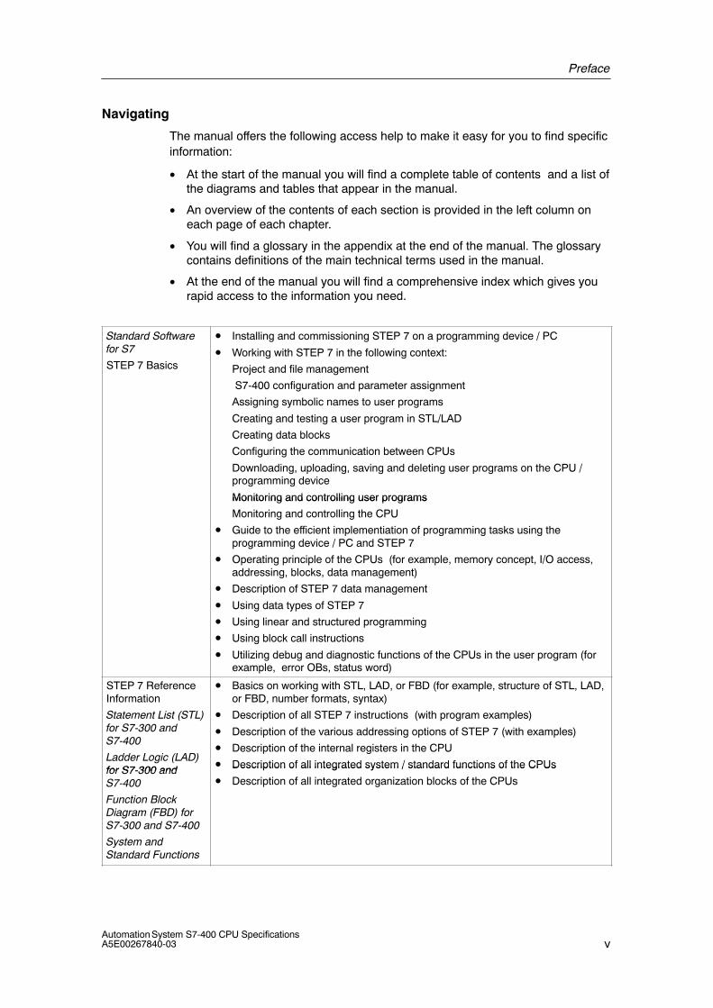
Standard Softwarefor S7
STEP 7 Basics
• Installing and commissioning STEP 7 on a programming device / PC
• Working with STEP 7 in the following context:
Project and file management
S7-400 configuration and parameter assignment
Assigning symbolic names to user programs
Creating and testing a user program in STL/LAD
Creating data blocks
Configuring the communication between CPUs
Downloading, uploading, saving and deleting user programs on the CPU /programming device
Monitoring and controlling user programsMonitoring and controlling user programs
Monitoring and controlling the CPU
• Guide to the efficient implementiation of programming tasks using theprogramming device / PC and STEP 7
• Operating principle of the CPUs (for example, memory concept, I/O access,addressing, blocks, data management)
• Description of STEP 7 data management
• Using data types of STEP 7
• Using linear and structured programming
• Using block call instructions
• Utilizing debug and diagnostic functions of the CPUs in the user program (forexample, error OBs, status word)
STEP 7 ReferenceInformation
Statement List (STL)for S7-300 andS7-400
Ladder Logic (LAD)for S7-300 and
• Basics on working with STL, LAD, or FBD (for example, structure of STL, LAD,or FBD, number formats, syntax)
• Description of all STEP 7 instructions (with program examples)
• Description of the various addressing options of STEP 7 (with examples)
• Description of the internal registers in the CPU
• Description of all integrated system / standard functions of the CPUsfor S7-300 andS7-400
Function BlockDiagram (FBD) forS7-300 and S7-400
System andStandard Functions
Description of all integrated system / standard functions of the CPUs
• Description of all integrated organization blocks of the CPUs
Preface
viAutomation System S7-400 CPU Specifications
A5E00267840-03
Recycling and Disposal
The S7-400 is low in contaminants and can therefore be recycled. To recycle anddispose of your old device in an environment-friendly manner, please contact adisposal company certified for disposal of electronic waste.
Further Support
If you have any further questions related to the use of your product for which youhave not found an answer in this documentation, please contact your Siemenspartner at your local Siemens office.
You can find your contact partner under:
http://www.siemens.com/automation/partner
A guide to out technical documentation for the various SIMATIC products andsystems is found under:
http://www.siemens.de/simatic–tech–doku–portal
The online catalog and order system is found under:
http://mall.ad.siemens.com
Training Centers
We offer various courses to newcomers to the SIMATIC S7 programmable logiccontroller. For details, please contact your regional training center or our centraltraining center in D 90327 Nuremberg, Germany:
Phone: +49 (911) 895-3200.
Internet: http://www.sitrain.com
Preface
viiAutomation System S7-400 CPU SpecificationsA5E00267840-03
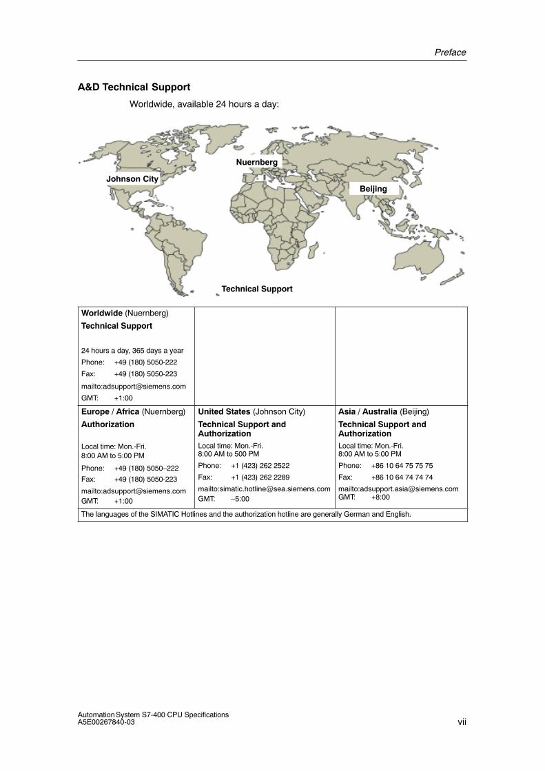
A&D Technical Support
Worldwide, available 24 hours a day:
Johnson City
Nuernberg
Beijing
Technical Support
Worldwide (Nuernberg)
Technical Support
24 hours a day, 365 days a year
Phone: +49 (180) 5050-222
Fax: +49 (180) 5050-223
mailto:[email protected]
GMT: +1:00
Europe / Africa (Nuernberg)
Authorization
Local time: Mon.-Fri. 8:00 AM to 5:00 PM
Phone: +49 (180) 5050–222
Fax: +49 (180) 5050-223
mailto:[email protected]: +1:00
United States (Johnson City)
Technical Support andAuthorizationLocal time: Mon.-Fri. 8:00 AM to 500 PM
Phone: +1 (423) 262 2522
Fax: +1 (423) 262 2289
mailto:[email protected]: –5:00
Asia / Australia (Beijing)
Technical Support andAuthorizationLocal time: Mon.-Fri. 8:00 AM to 5:00 PM
Phone: +86 10 64 75 75 75
Fax: +86 10 64 74 74 74
mailto:[email protected]: +8:00
The languages of the SIMATIC Hotlines and the authorization hotline are generally German and English.
Preface
viiiAutomation System S7-400 CPU Specifications
A5E00267840-03
Service & Support on the Internet
In addition to our documentation, we offer our Know-how online on the internet at:
http://www.siemens.com/automation/service&support
where you will find the following:
• The newsletter, which constantly provides you with up–to–date information onyour products.
• The right documents via our Search function in Service & Support.
• A forum, where users and experts from all over the world exchange theirexperiences.
• Your local representative for Automation & Drives.
• Information on field service, repairs, spare parts and more under “Services”.
ixAutomation System S7-400 CPU SpecificationsA5E00267840-03
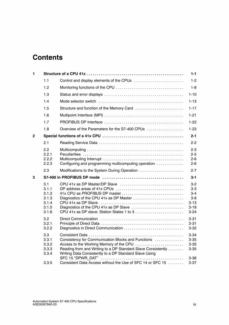
Contents
1 Structure of a CPU 41x 1-1. . . . . . . . . . . . . . . . . . . . . . . . . . . . . . . . . . . . . . . . . . . . . . . . . .
1.1 Control and display elements of the CPUs 1-2. . . . . . . . . . . . . . . . . . . . . . . . . .
1.2 Monitoring functions of the CPU 1-8. . . . . . . . . . . . . . . . . . . . . . . . . . . . . . . . . . .
1.3 Status and error displays 1-10. . . . . . . . . . . . . . . . . . . . . . . . . . . . . . . . . . . . . . . . .
1.4 Mode selector switch 1-13. . . . . . . . . . . . . . . . . . . . . . . . . . . . . . . . . . . . . . . . . . . .
1.5 Structure and function of the Memory Card 1-17. . . . . . . . . . . . . . . . . . . . . . . . .
1.6 Multipoint Interface (MPI) 1-21. . . . . . . . . . . . . . . . . . . . . . . . . . . . . . . . . . . . . . . . .
1.7 PROFIBUS DP Interface 1-22. . . . . . . . . . . . . . . . . . . . . . . . . . . . . . . . . . . . . . . . .
1.8 Overview of the Parameters for the S7-400 CPUs 1-23. . . . . . . . . . . . . . . . . . .
2 Special functions of a 41x CPU 2-1. . . . . . . . . . . . . . . . . . . . . . . . . . . . . . . . . . . . . . . . . .
2.1 Reading Service Data 2-2. . . . . . . . . . . . . . . . . . . . . . . . . . . . . . . . . . . . . . . . . . . .
2.2 Multicomputing 2-3. . . . . . . . . . . . . . . . . . . . . . . . . . . . . . . . . . . . . . . . . . . . . . . . . . 2.2.1 Peculiarities 2-5. . . . . . . . . . . . . . . . . . . . . . . . . . . . . . . . . . . . . . . . . . . . . . . . . . . . 2.2.2 Multicomputing Interrupt 2-6. . . . . . . . . . . . . . . . . . . . . . . . . . . . . . . . . . . . . . . . . . 2.2.3 Configuring and programming multicomputing operation 2-6. . . . . . . . . . . . . .
2.3 Modifications to the System During Operation 2-7. . . . . . . . . . . . . . . . . . . . . . .
3 S7-400 in PROFIBUS DP mode 3-1. . . . . . . . . . . . . . . . . . . . . . . . . . . . . . . . . . . . . . . . . .
3.1 CPU 41x as DP Master/DP Slave 3-2. . . . . . . . . . . . . . . . . . . . . . . . . . . . . . . . . 3.1.1 DP address areas of 41x CPUs 3-3. . . . . . . . . . . . . . . . . . . . . . . . . . . . . . . . . . . 3.1.2 41x CPU as PROFIBUS DP master 3-4. . . . . . . . . . . . . . . . . . . . . . . . . . . . . . . . 3.1.3 Diagnostics of the CPU 41x as DP Master 3-8. . . . . . . . . . . . . . . . . . . . . . . . . . 3.1.4 CPU 41x as DP Slave 3-13. . . . . . . . . . . . . . . . . . . . . . . . . . . . . . . . . . . . . . . . . . . 3.1.5 Diagnostics of the CPU 41x as DP Slave 3-18. . . . . . . . . . . . . . . . . . . . . . . . . . . 3.1.6 CPU 41x as DP slave: Station States 1 to 3 3-24. . . . . . . . . . . . . . . . . . . . . . . . .
3.2 Direct Communication 3-31. . . . . . . . . . . . . . . . . . . . . . . . . . . . . . . . . . . . . . . . . . . 3.2.1 Principle of Direct Data 3-31. . . . . . . . . . . . . . . . . . . . . . . . . . . . . . . . . . . . . . . . . . . 3.2.2 Diagnostics in Direct Communication 3-32. . . . . . . . . . . . . . . . . . . . . . . . . . . . . . .
3.3 Consistent Data 3-34. . . . . . . . . . . . . . . . . . . . . . . . . . . . . . . . . . . . . . . . . . . . . . . . . 3.3.1 Consistency for Communication Blocks and Functions 3-35. . . . . . . . . . . . . . . 3.3.2 Access to the Working Memory of the CPU 3-35. . . . . . . . . . . . . . . . . . . . . . . . . 3.3.3 Reading from and Writing to a DP Standard Slave Consistently 3-35. . . . . . . . 3.3.4 Writing Data Consistently to a DP Standard Slave Using
SFC 15 “DPWR_DAT” 3-36. . . . . . . . . . . . . . . . . . . . . . . . . . . . . . . . . . . . . . . . . . . 3.3.5 Consistent Data Access without the Use of SFC 14 or SFC 15 3-37. . . . . . . .
Contents
xAutomation System S7-400 CPU Specifications
A5E00267840-03
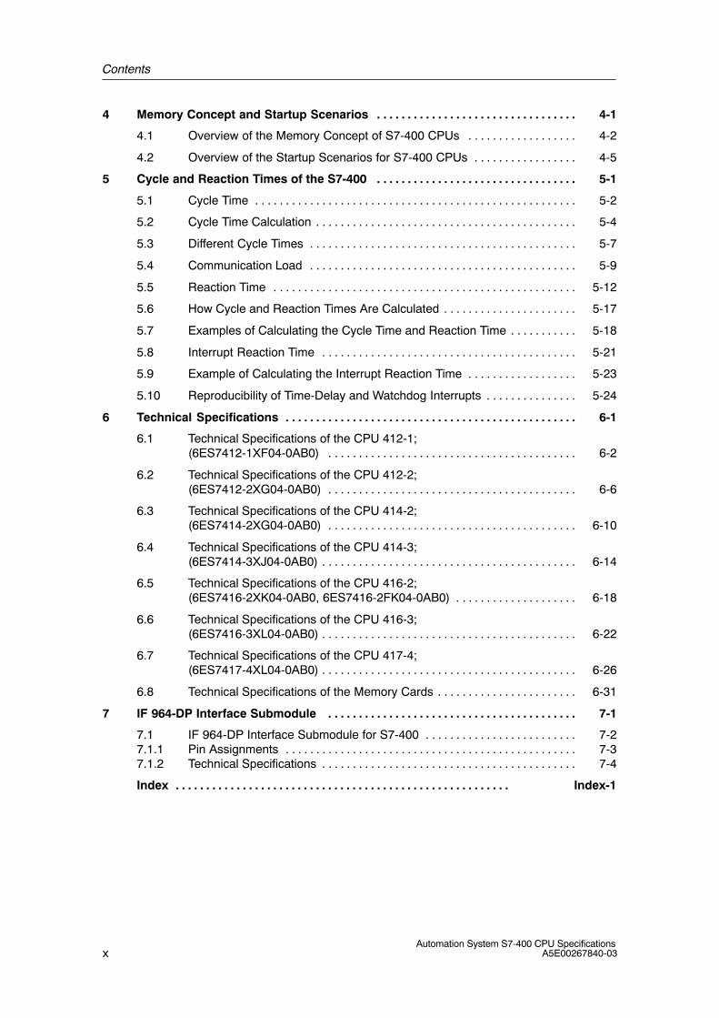
4 Memory Concept and Startup Scenarios 4-1. . . . . . . . . . . . . . . . . . . . . . . . . . . . . . . . .
4.1 Overview of the Memory Concept of S7-400 CPUs 4-2. . . . . . . . . . . . . . . . . .
4.2 Overview of the Startup Scenarios for S7-400 CPUs 4-5. . . . . . . . . . . . . . . . .
5 Cycle and Reaction Times of the S7-400 5-1. . . . . . . . . . . . . . . . . . . . . . . . . . . . . . . . .
5.1 Cycle Time 5-2. . . . . . . . . . . . . . . . . . . . . . . . . . . . . . . . . . . . . . . . . . . . . . . . . . . . .
5.2 Cycle Time Calculation 5-4. . . . . . . . . . . . . . . . . . . . . . . . . . . . . . . . . . . . . . . . . . .
5.3 Different Cycle Times 5-7. . . . . . . . . . . . . . . . . . . . . . . . . . . . . . . . . . . . . . . . . . . .
5.4 Communication Load 5-9. . . . . . . . . . . . . . . . . . . . . . . . . . . . . . . . . . . . . . . . . . . .
5.5 Reaction Time 5-12. . . . . . . . . . . . . . . . . . . . . . . . . . . . . . . . . . . . . . . . . . . . . . . . . .
5.6 How Cycle and Reaction Times Are Calculated 5-17. . . . . . . . . . . . . . . . . . . . . .
5.7 Examples of Calculating the Cycle Time and Reaction Time 5-18. . . . . . . . . . .
5.8 Interrupt Reaction Time 5-21. . . . . . . . . . . . . . . . . . . . . . . . . . . . . . . . . . . . . . . . . .
5.9 Example of Calculating the Interrupt Reaction Time 5-23. . . . . . . . . . . . . . . . . .
5.10 Reproducibility of Time-Delay and Watchdog Interrupts 5-24. . . . . . . . . . . . . . .
6 Technical Specifications 6-1. . . . . . . . . . . . . . . . . . . . . . . . . . . . . . . . . . . . . . . . . . . . . . . .
6.1 Technical Specifications of the CPU 412-1; (6ES7412-1XF04-0AB0) 6-2. . . . . . . . . . . . . . . . . . . . . . . . . . . . . . . . . . . . . . . . .
6.2 Technical Specifications of the CPU 412-2; (6ES7412-2XG04-0AB0) 6-6. . . . . . . . . . . . . . . . . . . . . . . . . . . . . . . . . . . . . . . . .
6.3 Technical Specifications of the CPU 414-2; (6ES7414-2XG04-0AB0) 6-10. . . . . . . . . . . . . . . . . . . . . . . . . . . . . . . . . . . . . . . . .
6.4 Technical Specifications of the CPU 414-3; (6ES7414-3XJ04-0AB0) 6-14. . . . . . . . . . . . . . . . . . . . . . . . . . . . . . . . . . . . . . . . . .
6.5 Technical Specifications of the CPU 416-2; (6ES7416-2XK04-0AB0, 6ES7416-2FK04-0AB0) 6-18. . . . . . . . . . . . . . . . . . . .
6.6 Technical Specifications of the CPU 416-3; (6ES7416-3XL04-0AB0) 6-22. . . . . . . . . . . . . . . . . . . . . . . . . . . . . . . . . . . . . . . . . .
6.7 Technical Specifications of the CPU 417-4; (6ES7417-4XL04-0AB0) 6-26. . . . . . . . . . . . . . . . . . . . . . . . . . . . . . . . . . . . . . . . . .
6.8 Technical Specifications of the Memory Cards 6-31. . . . . . . . . . . . . . . . . . . . . . .
7 IF 964-DP Interface Submodule 7-1. . . . . . . . . . . . . . . . . . . . . . . . . . . . . . . . . . . . . . . . .
7.1 IF 964-DP Interface Submodule for S7-400 7-2. . . . . . . . . . . . . . . . . . . . . . . . . 7.1.1 Pin Assignments 7-3. . . . . . . . . . . . . . . . . . . . . . . . . . . . . . . . . . . . . . . . . . . . . . . . 7.1.2 Technical Specifications 7-4. . . . . . . . . . . . . . . . . . . . . . . . . . . . . . . . . . . . . . . . . .
Index Index-1. . . . . . . . . . . . . . . . . . . . . . . . . . . . . . . . . . . . . . . . . . . . . . . . . . . . . . .
Contents
xiAutomation System S7-400 CPU SpecificationsA5E00267840-03
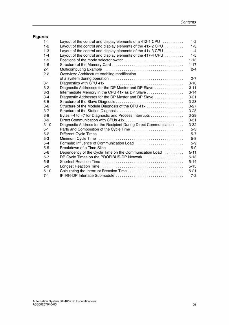
Figures1-1 Layout of the control and display elements of a 412-1 CPU 1-2. . . . . . . . . . . 1-2 Layout of the control and display elements of the 41x-2 CPU 1-3. . . . . . . . . . 1-3 Layout of the control and display elements of the 41x-3 CPU 1-4. . . . . . . . . . 1-4 Layout of the control and display elements of the 417-4 CPU 1-5. . . . . . . . . . 1-5 Positions of the mode selector switch 1-13. . . . . . . . . . . . . . . . . . . . . . . . . . . . . . 1-6 Structure of the Memory Card 1-17. . . . . . . . . . . . . . . . . . . . . . . . . . . . . . . . . . . . . 2-1 Multicomputing Example 2-4. . . . . . . . . . . . . . . . . . . . . . . . . . . . . . . . . . . . . . . . . 2-2 Overview: Architecture enabling modification
of a system during operation 2-7. . . . . . . . . . . . . . . . . . . . . . . . . . . . . . . . . . . . . . 3-1 Diagnostics with CPU 41x 3-10. . . . . . . . . . . . . . . . . . . . . . . . . . . . . . . . . . . . . . . . 3-2 Diagnostic Addresses for the DP Master and DP Slave 3-11. . . . . . . . . . . . . . . 3-3 Intermediate Memory in the CPU 41x as DP Slave 3-14. . . . . . . . . . . . . . . . . . . 3-4 Diagnostic Addresses for the DP Master and DP Slave 3-21. . . . . . . . . . . . . . . 3-5 Structure of the Slave Diagnosis 3-23. . . . . . . . . . . . . . . . . . . . . . . . . . . . . . . . . . . 3-6 Structure of the Module Diagnosis of the CPU 41x 3-27. . . . . . . . . . . . . . . . . . . 3-7 Structure of the Station Diagnosis 3-28. . . . . . . . . . . . . . . . . . . . . . . . . . . . . . . . . 3-8 Bytes +4 to +7 for Diagnostic and Process Interrupts 3-29. . . . . . . . . . . . . . . . . 3-9 Direct Communication with CPUs 41x 3-31. . . . . . . . . . . . . . . . . . . . . . . . . . . . . . 3-10 Diagnostic Address for the Recipient During Direct Communication 3-32. . . . 5-1 Parts and Composition of the Cycle Time 5-3. . . . . . . . . . . . . . . . . . . . . . . . . . . 5-2 Different Cycle Times 5-7. . . . . . . . . . . . . . . . . . . . . . . . . . . . . . . . . . . . . . . . . . . . 5-3 Minimum Cycle Time 5-8. . . . . . . . . . . . . . . . . . . . . . . . . . . . . . . . . . . . . . . . . . . . 5-4 Formula: Influence of Communication Load 5-9. . . . . . . . . . . . . . . . . . . . . . . . . 5-5 Breakdown of a Time Slice 5-9. . . . . . . . . . . . . . . . . . . . . . . . . . . . . . . . . . . . . . . 5-6 Dependency of the Cycle Time on the Communication Load 5-11. . . . . . . . . . 5-7 DP Cycle Times on the PROFIBUS-DP Network 5-13. . . . . . . . . . . . . . . . . . . . . 5-8 Shortest Reaction Time 5-14. . . . . . . . . . . . . . . . . . . . . . . . . . . . . . . . . . . . . . . . . . 5-9 Longest Reaction Time 5-15. . . . . . . . . . . . . . . . . . . . . . . . . . . . . . . . . . . . . . . . . . . 5-10 Calculating the Interrupt Reaction Time 5-21. . . . . . . . . . . . . . . . . . . . . . . . . . . . . 7-1 IF 964-DP Interface Submodule 7-2. . . . . . . . . . . . . . . . . . . . . . . . . . . . . . . . . . .
Contents
xiiAutomation System S7-400 CPU Specifications
A5E00267840-03
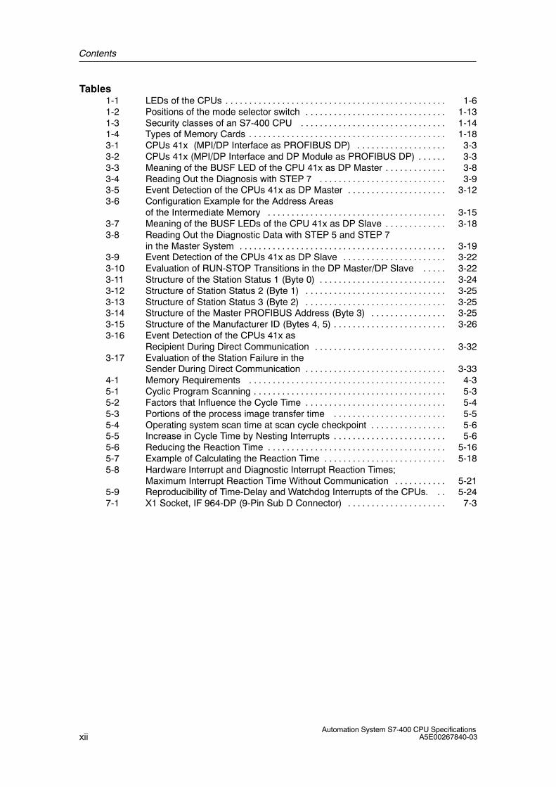
Tables1-1 LEDs of the CPUs 1-6. . . . . . . . . . . . . . . . . . . . . . . . . . . . . . . . . . . . . . . . . . . . . . . 1-2 Positions of the mode selector switch 1-13. . . . . . . . . . . . . . . . . . . . . . . . . . . . . . 1-3 Security classes of an S7-400 CPU 1-14. . . . . . . . . . . . . . . . . . . . . . . . . . . . . . . 1-4 Types of Memory Cards 1-18. . . . . . . . . . . . . . . . . . . . . . . . . . . . . . . . . . . . . . . . . . 3-1 CPUs 41x (MPI/DP Interface as PROFIBUS DP) 3-3. . . . . . . . . . . . . . . . . . . 3-2 CPUs 41x (MPI/DP Interface and DP Module as PROFIBUS DP) 3-3. . . . . . 3-3 Meaning of the BUSF LED of the CPU 41x as DP Master 3-8. . . . . . . . . . . . . 3-4 Reading Out the Diagnosis with STEP 7 3-9. . . . . . . . . . . . . . . . . . . . . . . . . . . 3-5 Event Detection of the CPUs 41x as DP Master 3-12. . . . . . . . . . . . . . . . . . . . . 3-6 Configuration Example for the Address Areas
of the Intermediate Memory 3-15. . . . . . . . . . . . . . . . . . . . . . . . . . . . . . . . . . . . . . 3-7 Meaning of the BUSF LEDs of the CPU 41x as DP Slave 3-18. . . . . . . . . . . . . 3-8 Reading Out the Diagnostic Data with STEP 5 and STEP 7
in the Master System 3-19. . . . . . . . . . . . . . . . . . . . . . . . . . . . . . . . . . . . . . . . . . . . 3-9 Event Detection of the CPUs 41x as DP Slave 3-22. . . . . . . . . . . . . . . . . . . . . . 3-10 Evaluation of RUN-STOP Transitions in the DP Master/DP Slave 3-22. . . . . 3-11 Structure of the Station Status 1 (Byte 0) 3-24. . . . . . . . . . . . . . . . . . . . . . . . . . . 3-12 Structure of Station Status 2 (Byte 1) 3-25. . . . . . . . . . . . . . . . . . . . . . . . . . . . . . 3-13 Structure of Station Status 3 (Byte 2) 3-25. . . . . . . . . . . . . . . . . . . . . . . . . . . . . . 3-14 Structure of the Master PROFIBUS Address (Byte 3) 3-25. . . . . . . . . . . . . . . . 3-15 Structure of the Manufacturer ID (Bytes 4, 5) 3-26. . . . . . . . . . . . . . . . . . . . . . . . 3-16 Event Detection of the CPUs 41x as
Recipient During Direct Communication 3-32. . . . . . . . . . . . . . . . . . . . . . . . . . . . 3-17 Evaluation of the Station Failure in the
Sender During Direct Communication 3-33. . . . . . . . . . . . . . . . . . . . . . . . . . . . . . 4-1 Memory Requirements 4-3. . . . . . . . . . . . . . . . . . . . . . . . . . . . . . . . . . . . . . . . . . 5-1 Cyclic Program Scanning 5-3. . . . . . . . . . . . . . . . . . . . . . . . . . . . . . . . . . . . . . . . . 5-2 Factors that Influence the Cycle Time 5-4. . . . . . . . . . . . . . . . . . . . . . . . . . . . . . 5-3 Portions of the process image transfer time 5-5. . . . . . . . . . . . . . . . . . . . . . . . 5-4 Operating system scan time at scan cycle checkpoint 5-6. . . . . . . . . . . . . . . . 5-5 Increase in Cycle Time by Nesting Interrupts 5-6. . . . . . . . . . . . . . . . . . . . . . . . 5-6 Reducing the Reaction Time 5-16. . . . . . . . . . . . . . . . . . . . . . . . . . . . . . . . . . . . . . 5-7 Example of Calculating the Reaction Time 5-18. . . . . . . . . . . . . . . . . . . . . . . . . . 5-8 Hardware Interrupt and Diagnostic Interrupt Reaction Times;
Maximum Interrupt Reaction Time Without Communication 5-21. . . . . . . . . . . 5-9 Reproducibility of Time-Delay and Watchdog Interrupts of the CPUs. 5-24. . 7-1 X1 Socket, IF 964-DP (9-Pin Sub D Connector) 7-3. . . . . . . . . . . . . . . . . . . . .
1-1Automation System S7-400 CPU SpecificationsA5E00267840-03
Structure of a CPU 41x
Chapter Overview
In Section You Will Find On Page
1.1 Control and display elements of the CPUs 1-2
1.2 Monitoring functions of the CPU 1-8
1.3 Status and error displays 1-10
1.4 Mode selector switch 1-13
1.5 Structure and function of the Memory Card 1-17
1.6 Multipoint Interface (MPI) 1-21
1.7 PROFIBUS DP Interface 1-22
1.8 Overview of the Parameters for the S7-400 CPUs 1-23
1
Structure of a CPU 41x
1-2Automation System S7-400 CPU Specifications
A5E00267840-03
1.1 Control and display elements of the CPUs
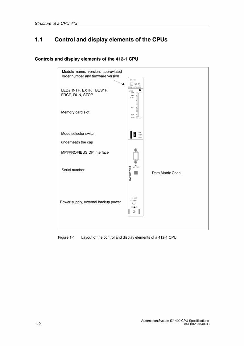
Controls and display elements of the 412-1 CPU
Mode selector switch
Memory card slot
Power supply, external backup power
underneath the cap
LEDs INTF, EXTF, BUS1F,FRCE, RUN, STOP
MPI/PROFIBUS DP interface
Module name, version, abbreviatedorder number and firmware version
BUS1F
CPU 412-1
6ES7412-1XF04-0AB0
V 4.0.0
SV
PS
3176
98
Serial numberData Matrix Code
Figure 1-1 Layout of the control and display elements of a 412-1 CPU
Structure of a CPU 41x
1-3Automation System S7-400 CPU SpecificationsA5E00267840-03
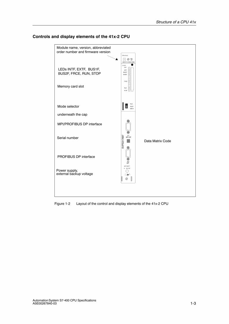
Controls and display elements of the 41x-2 CPU
Mode selector
Memory card slot
Power supply,
underneath the cap
LEDs INTF, EXTF, BUS1F,BUS2F, FRCE, RUN, STOP
MPI/PROFIBUS DP interface
PROFIBUS DP interface
Module name, version, abbreviatedorder number and firmware version
external backup voltage
BUS1F
BUS2F
CPU 414-2
6ES7414-2XG04-0AB0
Data Matrix Code
SV
PS
3176
97
V 4.0.0
Serial number
Figure 1-2 Layout of the control and display elements of the 41x-2 CPU
Structure of a CPU 41x
1-4Automation System S7-400 CPU Specifications
A5E00267840-03
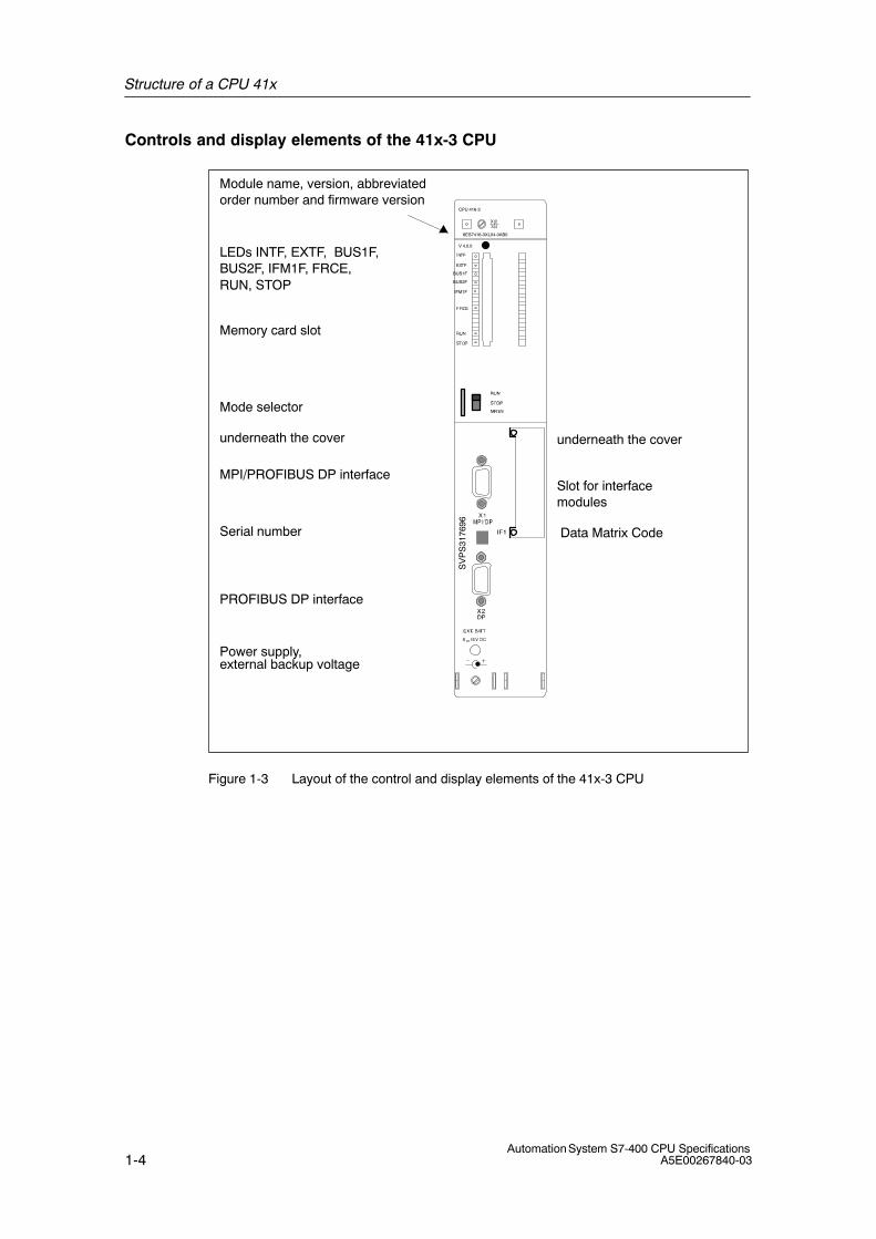
Controls and display elements of the 41x-3 CPU
Mode selector
Memory card slot
underneath the coverunderneath the cover
Slot for interfacemodules
LEDs INTF, EXTF, BUS1F,BUS2F, IFM1F, FRCE,RUN, STOP
MPI/PROFIBUS DP interface
PROFIBUS DP interface
Module name, version, abbreviatedorder number and firmware version
Power supply, external backup voltage
BUS1F
BUS2F
IFM1F
CPU 416-3
6ES7416-3XL04-0AB0
Serial number Data Matrix Code
SV
PS
3176
96
V 4.0.0
Figure 1-3 Layout of the control and display elements of the 41x-3 CPU
Structure of a CPU 41x
1-5Automation System S7-400 CPU SpecificationsA5E00267840-03
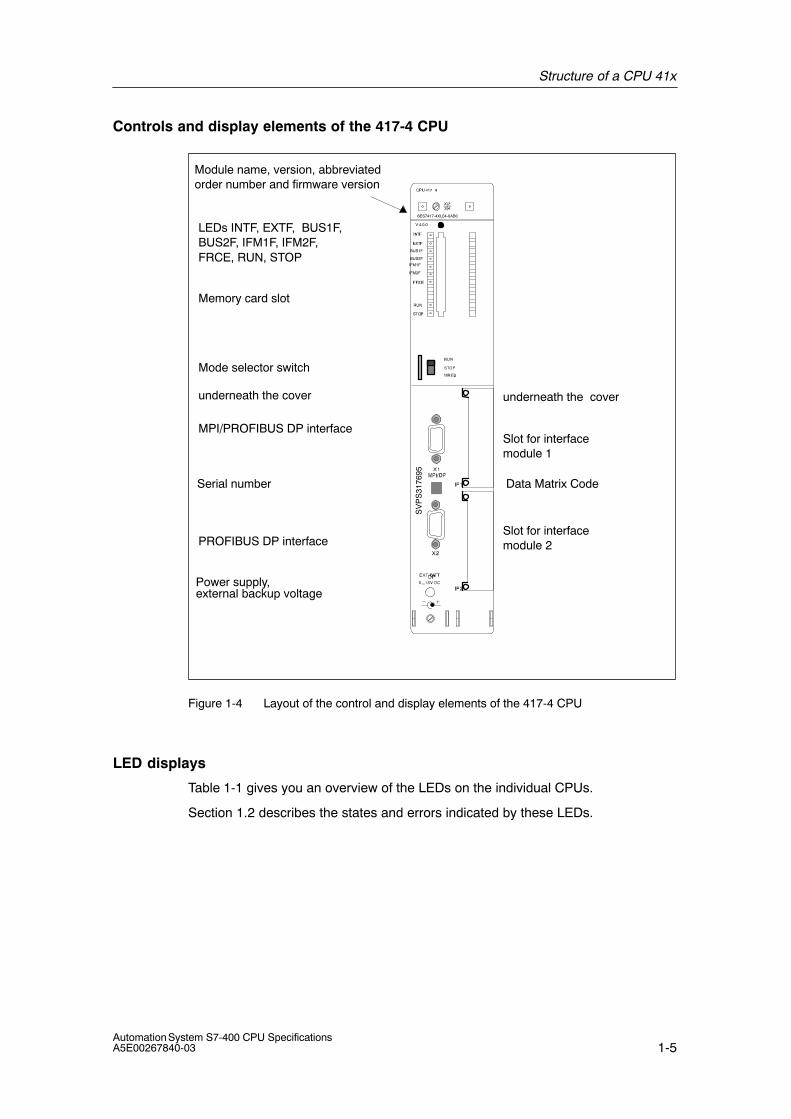
Controls and display elements of the 417-4 CPU
Mode selector switch
Memory card slot
underneath the coverunderneath the cover
Slot for interfacemodule 1
Slot for interfacemodule 2
LEDs INTF, EXTF, BUS1F,BUS2F, IFM1F, IFM2F,FRCE, RUN, STOP
MPI/PROFIBUS DP interface
PROFIBUS DP interface
Module name, version, abbreviatedorder number and firmware version
Power supply, external backup voltage
BUS1F
BUS2F
IFM1F
IFM2F
6ES7417-4XL04-0AB0
Serial number
SV
PS
3176
95
Data Matrix Code
V 4.0.0
Figure 1-4 Layout of the control and display elements of the 417-4 CPU
LED displays
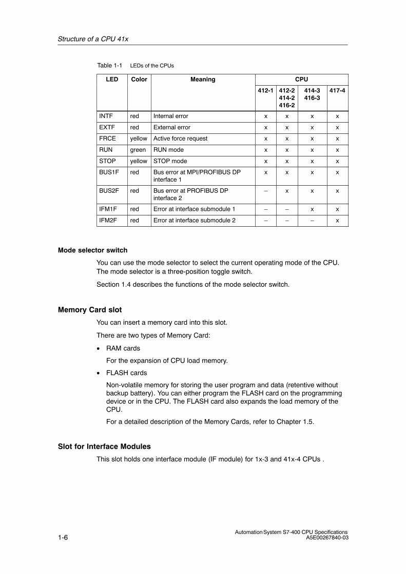
Table 1-1 gives you an overview of the LEDs on the individual CPUs.
Section 1.2 describes the states and errors indicated by these LEDs.
Structure of a CPU 41x
1-6Automation System S7-400 CPU Specifications
A5E00267840-03
Table 1-1 LEDs of the CPUs
LED Color Meaning CPU
412-1 412-2414-2416-2
414-3416-3
417-4
INTF red Internal error x x x x
EXTF red External error x x x x
FRCE yellow Active force request x x x x
RUN green RUN mode x x x x
STOP yellow STOP mode x x x x
BUS1F red Bus error at MPI/PROFIBUS DPinterface 1
x x x x
BUS2F red Bus error at PROFIBUS DP interface 2
– x x x
IFM1F red Error at interface submodule 1 – – x x
IFM2F red Error at interface submodule 2 – – – x
Mode selector switch
You can use the mode selector to select the current operating mode of the CPU.The mode selector is a three-position toggle switch.
Section 1.4 describes the functions of the mode selector switch.
Memory Card slot
You can insert a memory card into this slot.
There are two types of Memory Card:
• RAM cards
For the expansion of CPU load memory.
• FLASH cards
Non-volatile memory for storing the user program and data (retentive withoutbackup battery). You can either program the FLASH card on the programmingdevice or in the CPU. The FLASH card also expands the load memory of theCPU.
For a detailed description of the Memory Cards, refer to Chapter 1.5.
Slot for Interface Modules
This slot holds one interface module (IF module) for 1x-3 and 41x-4 CPUs .
Structure of a CPU 41x
1-7Automation System S7-400 CPU SpecificationsA5E00267840-03
MPI/DP interface
Devices you can connect to the MPI interface of the CPU, for example:
• Programming devices
• Control and monitoring devices
• Further S7-400 or S7-300 PLCs (see chapter 1.6).
Use the bus connector with angular cable outlet (see the manual Hardware andInstallation, Chapter 7)
You can also configure the MPI interface as DP master in order to use it asPROFIBUS DP interface with up to 32 DP slaves.
PROFIBUS DP interface
Lets you connect the distributed I/O, programming devices/OPs and furtherDP master stations.
POwer supply, external backup voltage at the “EXT.-BATT.” connector
You can install either one or two backup batteries in the S7-400 power supplymodules, depending on the module type. By doing so, you:
• Backup the user program in RAM memory.
• Retain the values of flags, timers, counters, system data and data of dynamicDBs.
• Backup the internal clock.
You can achieve the same effects by supplying a voltage between 5 V DC and15 V DC to the “EXT.-BATT.” connector of the CPU.
Properties of the “EXT.-BATT.” input:
• Polarity reversal protection
• Short-circuit current limited to 20 mA
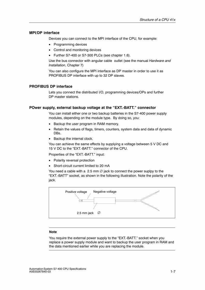
You need a cable with a 2.5 mm ∅ jack to connect the power suplpy to the“EXT.-BATT” socket, as shown in the following illustration. Note the polarity of thejack.
Positive voltage Negative voltage
2.5 mm jack ∅
Note
You require the external power supply to the “EXT.-BATT.” socket when youreplace a power supply module and want to backup the user program in RAM andthe data mentioned earlier while you are replacing the module.
Structure of a CPU 41x
1-8Automation System S7-400 CPU Specifications
A5E00267840-03
1.2 Monitoring functions of the CPU
Monitoring and error messages
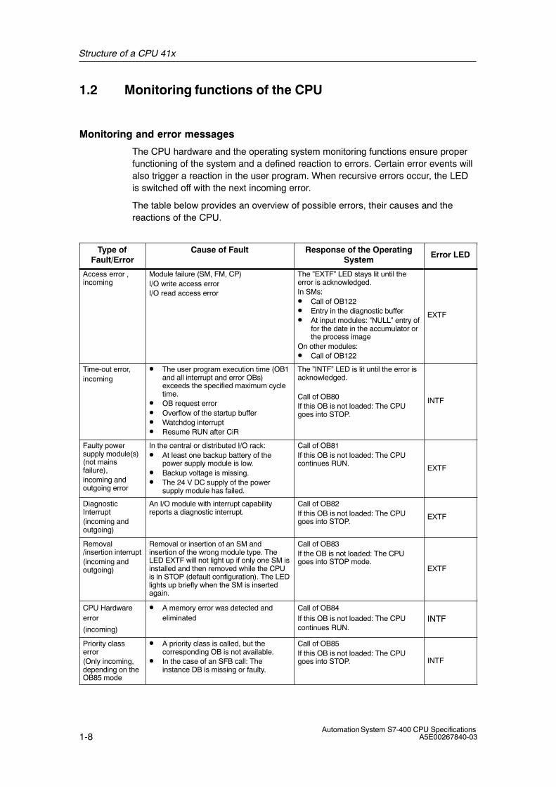
The CPU hardware and the operating system monitoring functions ensure properfunctioning of the system and a defined reaction to errors. Certain error events willalso trigger a reaction in the user program. When recursive errors occur, the LEDis switched off with the next incoming error.
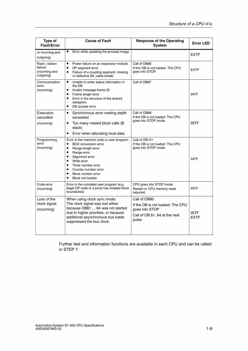
The table below provides an overview of possible errors, their causes and thereactions of the CPU.
Type ofFault/Error
Cause of Fault Response of the OperatingSystem
Error LED
Access error ,incoming
Module failure (SM, FM, CP)I/O write access errorI/O read access error
The ”EXTF” LED stays lit until theerror is acknowledged.In SMs:• Call of OB122• Entry in the diagnostic buffer• At input modules: “NULL” entry of
for the date in the accumulator orthe process image
On other modules:• Call of OB122
EXTF
Time-out error,incoming
• The user program execution time (OB1and all interrupt and error OBs)exceeds the specified maximum cycletime.
• OB request error• Overflow of the startup buffer• Watchdog interrupt• Resume RUN after CiR
The ”INTF” LED is lit until the error isacknowledged.
Call of OB80If this OB is not loaded: The CPUgoes into STOP.
INTF
Faulty powersupply module(s)(not mainsfailure),incoming andoutgoing error
In the central or distributed I/O rack:• At least one backup battery of the
power supply module is low.• Backup voltage is missing.• The 24 V DC supply of the power
supply module has failed.
Call of OB81If this OB is not loaded: The CPUcontinues RUN.
EXTF
DiagnosticInterrupt(incoming andoutgoing)
An I/O module with interrupt capabilityreports a diagnostic interrupt.
Call of OB82If this OB is not loaded: The CPUgoes into STOP.
EXTF
Removal/insertion interrupt(incoming andoutgoing)
Removal or insertion of an SM andinsertion of the wrong module type. TheLED EXTF will not light up if only one SM isinstalled and then removed while the CPUis in STOP (default configuration). The LEDlights up briefly when the SM is insertedagain.
Call of OB83If the OB is not loaded: The CPUgoes into STOP mode.
EXTF
CPU Hardwareerror
(incoming)
• A memory error was detected andeliminated
Call of OB84If this OB is not loaded: The CPUcontinues RUN.
INTF
Priority classerror(Only incoming,depending on theOB85 mode
• A priority class is called, but thecorresponding OB is not available.
• In the case of an SFB call: Theinstance DB is missing or faulty.
Call of OB85If this OB is not loaded: The CPUgoes into STOP. INTF
Structure of a CPU 41x
1-9Automation System S7-400 CPU SpecificationsA5E00267840-03
Type ofFault/Error Error LED
Response of the OperatingSystem
Cause of Fault
or incoming and
outgoing)
• Error while updating the process imageEXTF
Rack / stationfailure(incoming andoutgoing)
• Power failure on an expansion module• DP segment error• Failure of a coupling segment: missing
or defective IM, cable break)
Call of OB86If this OB is not loaded: The CPUgoes into STOP. EXTF
Communicationerror(incoming)
• Unable to enter status information inthe DB
• Invalid message frame ID• Frame length error• Error in the structure of the shared
datagram• DB access error
Call of OB87
INTF
Executioncancelled
(incoming)
• Synchronous error nesting depthexceeded
• Too many nested block calls (Bstack)
• Error when allocating local data
Call of OB88If the OB is not loaded: The CPUgoes into STOP mode.
INTF
Programmingerror(incoming)
Error in the machine code or user program:• BCD conversion error• Range length error• Range error• Alignment error• Write error• Timer number error• Counter number error• Block number error• Block not loaded
Call of OB121If the OB is not loaded: The CPUgoes into STOP mode.
INTF
Code error(incoming)
Error in the compiled user program (e.g.ilegal OP code or a jump has violated blockboundaries)
CPU goes into STOP mode.Restart or CPU memory resetrequired.
INTF
Loss of theclock signal
(incoming)
When using clock sync mode: The clock signal was lost eitherbecause OB61 ... 64 was not starteddue to higher priorities, or becauseadditional asynchronous bus loadssuppressed the bus clock.
Call of OB80
If the OB is not loaded: The CPUgoes into STOP
Call of OB 61..64 at the nextpulse.
INTFEXTF
Further test and information functions are available in each CPU and can be calledin STEP 7.
Structure of a CPU 41x
1-10Automation System S7-400 CPU Specifications
A5E00267840-03
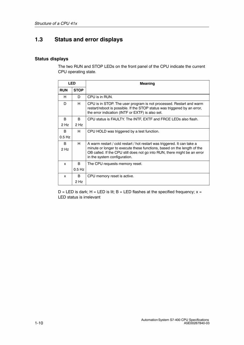
1.3 Status and error displays
Status displays
The two RUN and STOP LEDs on the front panel of the CPU indicate the currentCPU operating state.
LED Meaning
RUN STOP
H D CPU is in RUN.
D H CPU is in STOP. The user program is not processed. Restart and warmrestart/reboot is possible. If the STOP status was triggered by an error,the error indication (INTF or EXTF) is also set.
B
2 Hz
B
2 Hz
CPU status is FAULTY. The INTF, EXTF and FRCE LEDs also flash.
B
0.5 Hz
H CPU HOLD was triggered by a test function.
B
2 Hz
H A warm restart / cold restart / hot restart was triggered. It can take aminute or longer to execute these functions, based on the length of theOB called. If the CPU still does not go into RUN, there might be an errorin the system configuration.
x B
0.5 Hz
The CPU requests memory reset.
x B
2 Hz
CPU memory reset is active.
D = LED is dark; H = LED is lit; B = LED flashes at the specified frequency; x =LED status is irrelevant
Structure of a CPU 41x
1-11Automation System S7-400 CPU SpecificationsA5E00267840-03
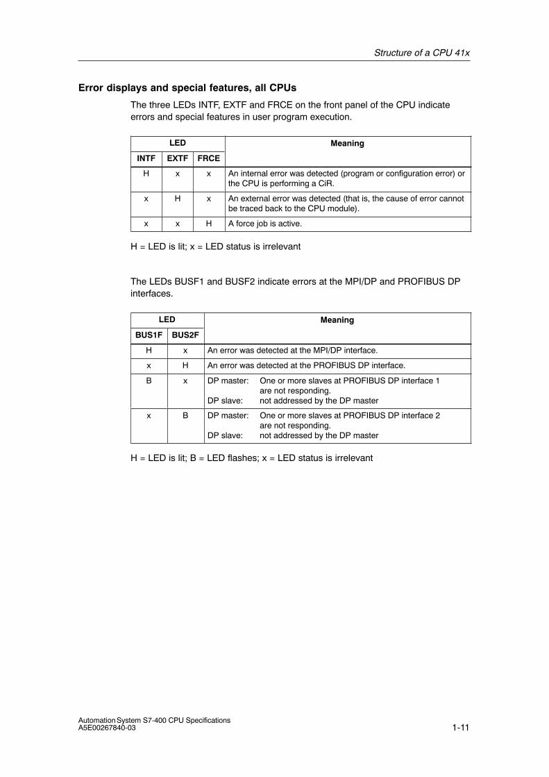
Error displays and special features, all CPUs
The three LEDs INTF, EXTF and FRCE on the front panel of the CPU indicateerrors and special features in user program execution.
LED Meaning
INTF EXTF FRCE
H x x An internal error was detected (program or configuration error) orthe CPU is performing a CiR.
x H x An external error was detected (that is, the cause of error cannotbe traced back to the CPU module).
x x H A force job is active.
H = LED is lit; x = LED status is irrelevant
The LEDs BUSF1 and BUSF2 indicate errors at the MPI/DP and PROFIBUS DPinterfaces.
LED Meaning
BUS1F BUS2F
H x An error was detected at the MPI/DP interface.
x H An error was detected at the PROFIBUS DP interface.
B x DP master: One or more slaves at PROFIBUS DP interface 1are not responding.
DP slave: not addressed by the DP master
x B DP master: One or more slaves at PROFIBUS DP interface 2are not responding.
DP slave: not addressed by the DP master
H = LED is lit; B = LED flashes; x = LED status is irrelevant
Structure of a CPU 41x
1-12Automation System S7-400 CPU Specifications
A5E00267840-03
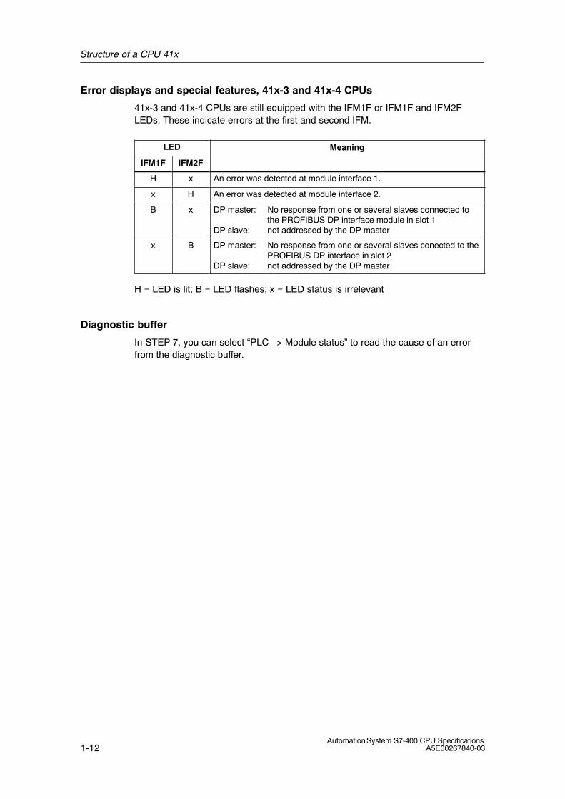
Error displays and special features, 41x-3 and 41x-4 CPUs
41x-3 and 41x-4 CPUs are still equipped with the IFM1F or IFM1F and IFM2FLEDs. These indicate errors at the first and second IFM.
LED Meaning
IFM1F IFM2F
H x An error was detected at module interface 1.
x H An error was detected at module interface 2.
B x DP master: No response from one or several slaves connected to the PROFIBUS DP interface module in slot 1
DP slave: not addressed by the DP master
x B DP master: No response from one or several slaves conected to thePROFIBUS DP interface in slot 2
DP slave: not addressed by the DP master
H = LED is lit; B = LED flashes; x = LED status is irrelevant
Diagnostic buffer
In STEP 7, you can select “PLC –> Module status” to read the cause of an errorfrom the diagnostic buffer.
Structure of a CPU 41x
1-13Automation System S7-400 CPU SpecificationsA5E00267840-03
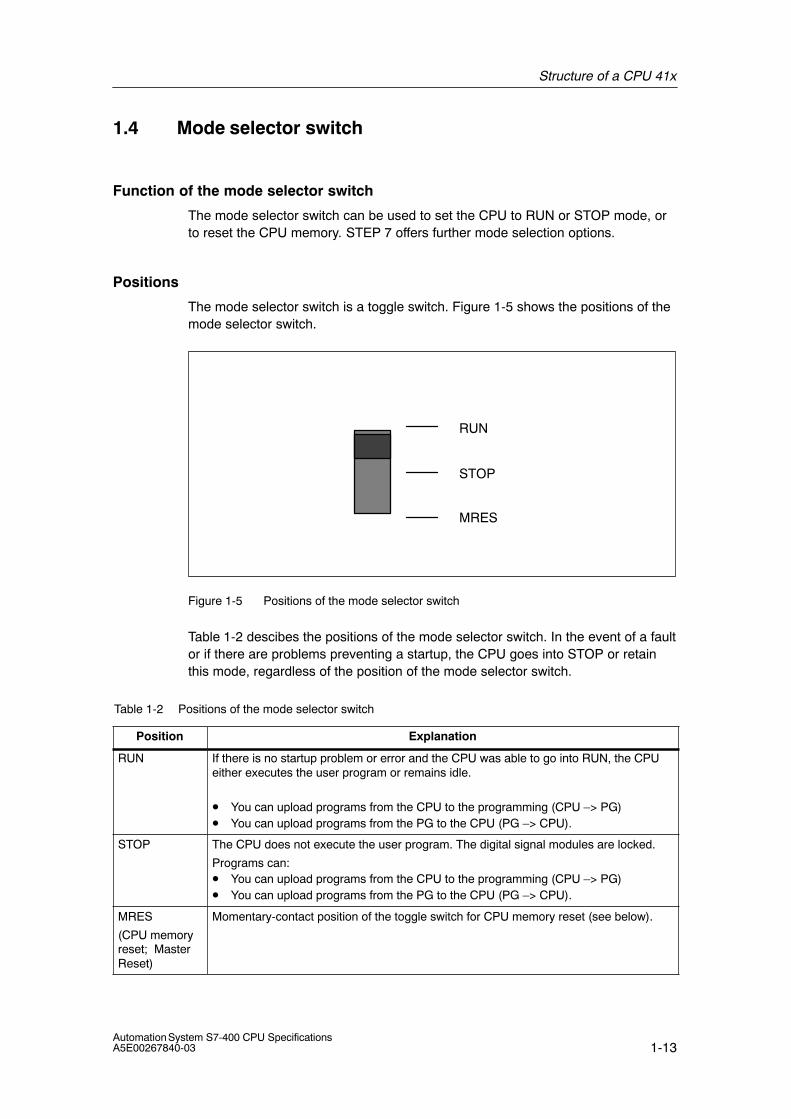
1.4 Mode selector switch
Function of the mode selector switch
The mode selector switch can be used to set the CPU to RUN or STOP mode, orto reset the CPU memory. STEP 7 offers further mode selection options.
Positions
The mode selector switch is a toggle switch. Figure 1-5 shows the positions of themode selector switch.
RUN
STOP
MRES
Figure 1-5 Positions of the mode selector switch
Table 1-2 descibes the positions of the mode selector switch. In the event of a faultor if there are problems preventing a startup, the CPU goes into STOP or retainthis mode, regardless of the position of the mode selector switch.
Table 1-2 Positions of the mode selector switch
Position Explanation
RUN If there is no startup problem or error and the CPU was able to go into RUN, the CPUeither executes the user program or remains idle.
• You can upload programs from the CPU to the programming (CPU –> PG)• You can upload programs from the PG to the CPU (PG –> CPU).
STOP The CPU does not execute the user program. The digital signal modules are locked.
Programs can:• You can upload programs from the CPU to the programming (CPU –> PG)• You can upload programs from the PG to the CPU (PG –> CPU).
MRES
(CPU memoryreset; MasterReset)
Momentary-contact position of the toggle switch for CPU memory reset (see below).
Structure of a CPU 41x
1-14Automation System S7-400 CPU Specifications
A5E00267840-03
Security classes
A security class can be agreed for S7-400 CPUs in order to prevent unauthorizedaccess to CPU programs. You can define a security class which allows usersaccess to PG functions without particular authorization (password). On passwordlevel you can access all PG functions.
Setting the security classes
You can set the security classes (1 to 3) for a CPU by calling STEP 7 –> HWConfig.
You can delete the the security class set STEP 7 –> HW Config by means of amanual reset using the mode selector switch.
Table 1-3 lists the security classes of an S7-400 CPU.
Table 1-3 Security classes of an S7-400 CPU
Securityclass
Function
1 • Access to all programming device functions is allowed (default).
2 • Objects may be uploaded from the CPU to the PG. That is, only theread–only functions can be accessed on the PG.
• Access to process control, process monitoring and processcommunication functions is allowed.
• Access to the information functions is allowed.
3 • Access to process control, process monitoring and processcommunication functions is allowed.
• Access to the information functions is allowed.
Sequence for CPU memory reset
Case A: You want to download all data of a new user program to the CPU.
1. Set the switch to STOP.
Result: The STOP LED is lit.
2. Set the switch to MRES setting and hold it at this position.
Result: The STOP LED performs this cycle: 1 sec OFF –> 1 sec ON –> 1 secOFF –> continuous signal.
3. Reset the switch to STOP, then set MRES again within the next 3 seconds,then reset it to STOP.
Result: The STOP LED flashes at least 3 seconds at 2 Hz (memory reset isbeing executed), then its signal is set continuously.
Structure of a CPU 41x
1-15Automation System S7-400 CPU SpecificationsA5E00267840-03
Case B: The CPU requests memory reset, indicated by the flashing STOPLED (5 Hz). The system requests a CPU memory reset after a memory cardwas removed or inserted, for example.
Set the switch to MRES and then return it to STOP.
Result: The STOP LED flashes at least 3 seconds at 2 Hz (memory reset isbeing executed), then its signal is set continuously.
For detailed information on CPU memory reset refer to chapter 6 of the manualS7-400 Programmable Controllers Hardware and Installation.
CPU sequence for memory reset
The CPU performs the following processes for memory reset:
• It deletes the user program from work memory and in load memory (integratedRAM or RAM Card).
• It deletes all counters, flags and timers (except the time).
• It performs a hardware selftest.
• It initializes the hardware and system program parameters, that is, its internaldefault settings. Some of the configured defaults are taken into account.
• When a FLASH Card is inserted and after the CPU memory reset is completed,the CPU loads the user program and the system parameters from the FLASHCard to work memory.
What is retained after a CPU memory reset...
The following data are retained:
• The contents of the diagnostics buffer can be read by uploading it to the PG inSTEP 7.
• The parameters of the MPI interface (MPI address and highest MPI address).Note the special features shown in the table below.
• The time
• The status and value of the operating hours counter
Special feature: MPI parameters
A special situation is given for the MPI parameters when a CPU memory reset ispreformed. The table below shows which MPI parameter remain valid after a CPUmemory reset.
CPU memory reset ... MPI parameters...
with FLASH Card ..., stored on the FLASH Card are valid
without FLASH Card ...are retained in the CPU and valid
Structure of a CPU 41x
1-16Automation System S7-400 CPU Specifications
A5E00267840-03
Cold start
• During a cold start, all data (process image, flags, timers, counters and DBs)are reset to the start values stored in the program in load memory, regardlesswhether these are configured as retentive or non-retentive data.
• Program execution is restarted at the start position (OB100, OB101, OB102 orOB1).
Restart (warm start)
• A restart resets the process image and the non-retentive flags, timers, timesand counters.
Retentive flags, times and counters retain their last valid value.
All DBs assigned the “Non Retain” attribute are reset to load values. Theremaining DBs retain their last valid value.
• Program execution is restarted at the start position (startup OB or OB 1).
• After a power supply interruption, the warm restart function is only available inbackup mode.
Hot restart
• When a hot restart is performed, all data and the process image retain their lastvalid value.
• Program execution is resumed at the breakpoint.
• The outputs do not change their status until the current cycle is completed.
• After a power supply interruption, the hot restart function is only available inbackup mode.
Control sequence for restart (warm restart)
1. Set the switch to STOP.
Result: The STOP LED is lit.
2. Set the switch to RUN.
Control sequence for hot restart
1. Select “hot restart” via PG.
The correspondend button can be used only if a hot restart is possible whithyour CPU.
Control sequence for cold restart
A cold start can only be initiated on the PG.
Structure of a CPU 41x
1-17Automation System S7-400 CPU SpecificationsA5E00267840-03
1.5 Structure and function of the Memory Card
Order numbers
The order numbers for memory cards are listed in chapter 6 of the technicalspecification.
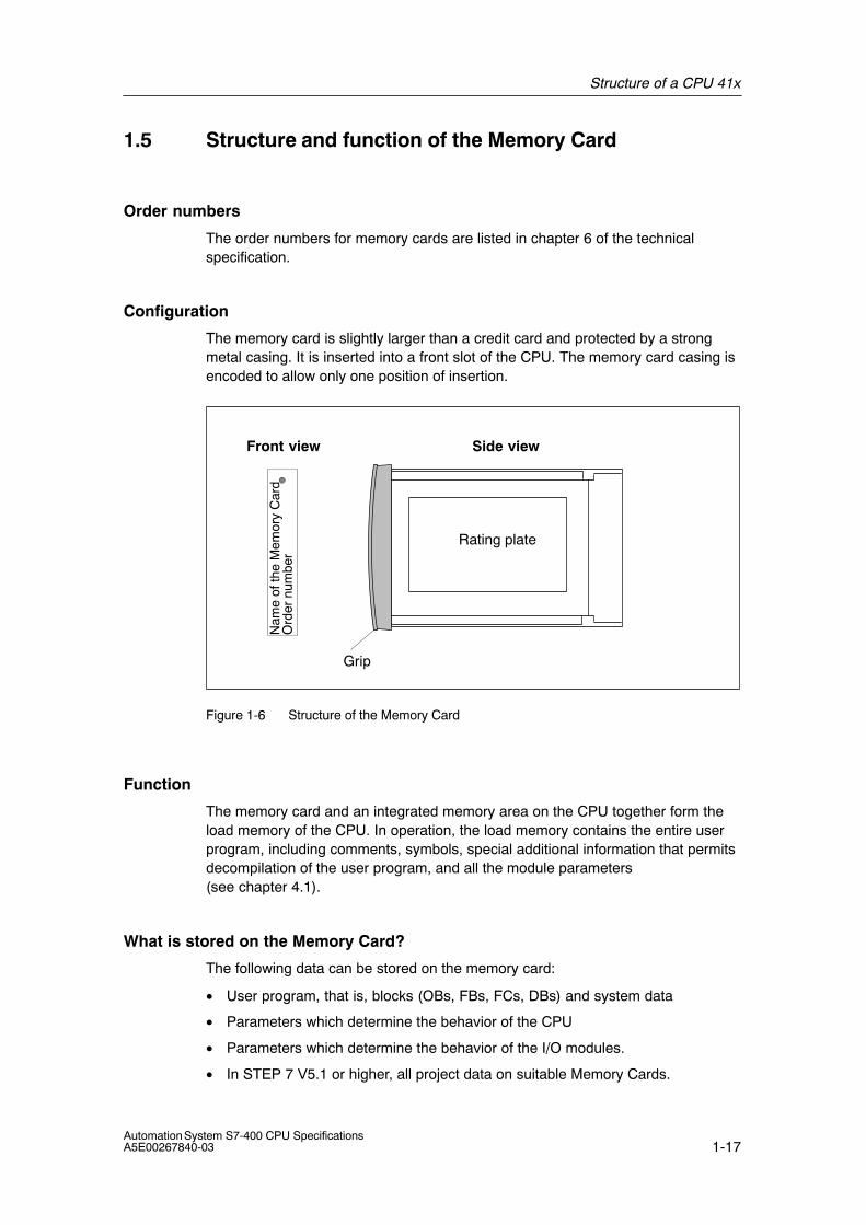
Configuration
The memory card is slightly larger than a credit card and protected by a strongmetal casing. It is inserted into a front slot of the CPU. The memory card casing isencoded to allow only one position of insertion.
Grip
Side view
Rating plate
Front view
Ord
er n
umbe
rN
ame
of th
e M
emor
y C
ard
Figure 1-6 Structure of the Memory Card
Function
The memory card and an integrated memory area on the CPU together form theload memory of the CPU. In operation, the load memory contains the entire userprogram, including comments, symbols, special additional information that permitsdecompilation of the user program, and all the module parameters (see chapter 4.1).
What is stored on the Memory Card?
The following data can be stored on the memory card:
• User program, that is, blocks (OBs, FBs, FCs, DBs) and system data
• Parameters which determine the behavior of the CPU
• Parameters which determine the behavior of the I/O modules.
• In STEP 7 V5.1 or higher, all project data on suitable Memory Cards.
Structure of a CPU 41x
1-18Automation System S7-400 CPU Specifications
A5E00267840-03
Types of Memory Cards for S7-400
Two types of memory card are used in the S7-400:
• RAM cards
• Flash cards (FEPROM cards)
Note
Non-Siemens memory cards cannot be used in the S7-400.
What type of Memory Card should I use?
Whether you use a RAM card or a Flash card depends on your application.
Table 1-4 Types of Memory Cards
If you ... ...Then
want to store the data in RAM and edit yourprogram in RUN,
use a RAM card
want to backup your user programpermanently on the memory card (withoutbackup battery or outside the CPU),
use a Flash card
RAM Card
To use a RAM card and load the user program, you must insert it into the CPUslot. The user program is loaded with the help of the programming device (PG).
You can load the entire user program or individual elements such as FBs, FCs,OBs, DBs, or SDBs to the load memory in when the CPU is in STOP mode orRUN.
All data on the RAM Card are lost when you remove it from the CPU. The RAMcard does not have a built-in backup battery.
If the power supply has a functioning backup battery or an external backup voltageis supplied to the CPU via the “EXT. BATT.” socket, the contents of the RAM cardare retained after power is switched off, provided the RAM card stays in the CPUand the CPU stays in the rack.
Structure of a CPU 41x
1-19Automation System S7-400 CPU SpecificationsA5E00267840-03
Flash Card
With a Flash card, you have two options of loading the user program:
• Set the CPU to STOP using the mode selector, plug the Flash card into theCPU, then load the user program with STEP 7 “PLC –> Load User Program to Memory Card”.
• Load the user program into the Flash card in offline mode at the programmingdevice or adapter and then insert the Flash card into the CPU.
You can only reload the full user program using the Flash card. You can loadsmaller program sections into the integrated load memory on the CPU using theprogramming device. In the case of extensive program changes, you must alwaysreload the Flash card with the full user program.
The Flash card does not require a backup voltage, that is, the information storedon it is retained even when you remove the Flash card from the CPU or if youoperate your S7-400 system without a buffering function (without backup battery inthe power supply module or “EXT. BATT.” socket of the CPU).
Which Memory Card Capacity to Use
The capacity of the memory card is determined by the size of the user programand the additional memory requirements when using function modules orcommunications modules. For information on memory requirements, refer to therelevant module manuals.
To optimze utilization of work memory (code and data) on your CPU, you shouldexpand the load memory of the CPU with a memory card which has at least thesame capacity as the work memory.

Structure of a CPU 41x
1-20Automation System S7-400 CPU Specifications
A5E00267840-03
Changing the Memory Card
To change the memory card:
1. Set the CPU to STOP.
2. Remove the memory card.
Note
If you remove the memory card, the CPU requests a memory reset in a 3-secsequence, which is indicated by the flashing STOP LED. This sequence cannot beinfluenced by error OBs.
3. Insert the “new” memory card.
4. Reset CPU memory.
Structure of a CPU 41x
1-21Automation System S7-400 CPU SpecificationsA5E00267840-03
1.6 Multipoint Interface (MPI)
Connectable devices
You can connect the following stations to the MPI, for example:
• Programming devices (PG/PC)
• Control and monitoring devices (OPs and TDs)
• Additional SIMATIC S7 PLCs
Some devices use the 24 V DC power supply of the interface. This voltageconnected to a reference potential.
PG/OP->CPU communication
A CPU is capable of maintaining several simultaneous online connections. Onlyone of these connections is reserved as default connection for a PG, and a secondfor the OP/ control and monitoring device.
For CPU-specific information on the number of connection resources ofconnectable OPs, refer to chapter 6 of the Technical Specifications.
Communication and interrupt response times
NoticeThe interrupt reaction times may be extended by read / write operations involvingthe maximum data length (approx. 460 byte).
CPU -> CPU communication
There are three types of CPU-CPU communication:
• Data transfer by means of S7 basic communication
• Data transfer by means of S7 communication
• Data transfer by means of global data communication
For further information, refer to the “Programming with STEP 7” manual.
Connectors
Always use bus connectors with angular cable outlet PROFIBUS DP or PG cablesused to connect devices to the MPI (see chapter 7 of the manual Hardware andInstallation ).
Multipoint interface as DP interface
You can also configure the MPI interface for operation as DP interface. To do so,you can reconfigure the MPI interface in SIMATIC Manager of STEP 7 . You canuse this to set up a DP segment consisting of up to 32 slaves.
Structure of a CPU 41x
1-22Automation System S7-400 CPU Specifications
A5E00267840-03
1.7 PROFIBUS DP Interface
Connectable devices
You can connect any compliant DP slave to the PROFIBUS DP interface.
Here, the CPU is operated either as a DP master or a DP slave which is connectedvia PROFIBUS DP field bus to the passive slave stations or other DP masters.
Some devices use the 24 V DC power supply of the interface. This voltageconnected to a reference potential.
Connectors
Always use the bus connector for PROFIBUS DP or PROFIBUS cables used toconnecting devices to the PROFIBUS DP interface (see chapter 7 of the manualHardware and Installation ).
Structure of a CPU 41x
1-23Automation System S7-400 CPU SpecificationsA5E00267840-03
1.8 Overview of the Parameters for the S7-400 CPUs
Default valuesAll parameters are assigned factory settings. These defaults are suitable for awhole range of standard applications, that is, an S7-400 can be used immediatelyas turnkey system which does not require any further settings.
You can define CPU-specific default values using the “HW Config” tool in STEP 7.
Parameter BlocksThe behavior and properties of the CPU are declared in the parameters which arestored in system data blocks. The CPUs are assigned default values. You can editthese default values by changing the parameters in HW Config.
The list below provides an overview of the configurable system properties of theCPUs.
• General properties (for example, the CPU name)
• Startup (for example, enabling a hot restart)
• Constant bus cycle time interrupts
• Cycles / memory flags (e.g. scan cycle cycle monitoring time)
• Retentivity (number of retentive tags, timers and counters)
• Memory (e.g. local data)
Note: If you change the work memory allocation by modifying parameters, thiswork memory is reorganized when you load system data to the CPU. The resultis, that the DBs which were generated by an SFC will be deleted, and theremaining DBs are assigned default initial values from load memory.
Work memory space available for storing code or DBs can be reorganizedwhen system data are loaded by changing the following parameters:
– Size of the process image (byte–oriented; on the “Cycle / clock flag” tab)
– Communication resources (on the “Memory” tab)
– Size of the diagnostics buffers (on the “Diagnostics / clock” tab)
– The amount of local data for all priority classes (“Memory” tab)
• Assignment of interrupts (process interrupts, delay interrupts, asynchronouserror interrupts) to the priority classes
• Time-of-day interrupts (e.g. start, interval duration, priority)
• Watchdog interrupts (e.g. priority, interval duration)
• Diagnostics/clock (e.g. time synchronization)
• Protection levels
Note
16 memory bytes and 8 counter numbers are set to retentive in the defaultsettings, in other words, they are not deleted when the CPU is restarted.
Structure of a CPU 41x
1-24Automation System S7-400 CPU Specifications
A5E00267840-03
Parameter Assignment Tool
You can set the individual CPU parameters using “Configuring Hardware” inSTEP 7.
NoteIf you make changes to the existing settings of the following parameters, theoperating system carries out initializations like those during cold restart.
• Size of the process image of the outputs
• Size of the process image of the inputs
• Size of the local data
• Number of diagnostic buffer inputs
• Communication resources
These initializations are:
• Data blocks are initialized with the load values
• Memory bits, times, counts, inputs and outputs are deleted regardless of the retentive settings (0)
• DBs generated via SFC are deleted
• Permanently configured, base communication connections are established
• All the priority classes start from the beginning again
2-1Automation System S7-400 CPU SpecificationsA5E00267840-03
Special functions of a 41x CPU
Chapter Overview
In Section You Will Find On Page
2.1 Read Service Data 2-2
2.2 Multicomputing 2-3
2.3 Modifications to the System During Operation 2-7
2
Special functions of a 41x CPU
2-2Automation System S7-400 CPU Specifications
A5E00267840-03
2.1 Reading Service Data
Requirements
This function requires STEP 7 V5.3 or higher.
When is this function used?
If you require service support, please contact your Siemens Customer SupportCenter. The Customer Support Center may request specific information about thestatus of the CPU in your system for analysis. This information is stored in thediagnostics buffer and in the actual service data.
Select the “PLC –> Save service data” menu command to read this information,then save the data to two files and send these to your Customer Support Center.
Please note:
• You should save all service data immediately after the CPU has changed toSTOP, or when a redundant system has lost its synchronization.
• Always save the service data of both CPUs in the redundant system, that is,including the data of the CPU which is still in RUN after synchronization is lost.
The service data are written to the file <filename.ext> in the <pathname> path.
Procedure
1. Select the “PLC –> Save service data” menu command
A dialog box opens where you can define a storage location and name for bothfiles.
2. Save the files.
3. Send these files to your Customer Support Center upon request.
Special functions of a 41x CPU
2-3Automation System S7-400 CPU SpecificationsA5E00267840-03
2.2 Multicomputing
Chapter overview
Section Description Page
2.2.1 Peculiarities 2-5
2.2.2 Multicomputing Interrupt 2-6
2.2.3 Configuring and programming multicomputing operation 2-6
What is multicomputing?
Multicomputing refers to the concurrent operation of several (max. 4) CPUs whichare capable of multicomputing in a central S7-400 system.
The participating CPUs automatically change their status in synchronism. That is,all CPUs are in synchronism during startup and transitions to STOP. Every CPUexecutes its own user program, irrespective of the user programs in the otherCPUs. This feature facilitates the execution of control tasks in parallel.
Which racks are suitable for multicomputing?
The racks listed below are suitable for multicomputing:
• UR1 and UR 2
• UR2-H, multicomputing with several CPUs is only possible if all CPUs areinserted in the same in the same unit.
• CR3, the CR3 is equipped only with four slots, that is, you can only operate twoCPUs in multicomputing mode.
Difference between multicomputing mode and operation in a segmented rack
The segmented rack CR2 (physically segmented, can not be configured in thesoftware) allows only one CPU per segment. This, however, is not amulticomputing system. The CPUs in the segmented rack form an independentunit and respond in the same way as single-processor systems. A shared logicaladdress space does not exist.
Hence, multicomputing is not possible in segmented racks (see also the installationmanual).
Special functions of a 41x CPU
2-4Automation System S7-400 CPU Specifications
A5E00267840-03
When do I use multicomputing?
In the following situations it is of advantage to use multicomputing:
• The size of your user program exceeds the capacity of a single CPU and yourun out of storage space: distribute program execution to several CPUs.
• A certain part of your system requires high-speed processing: cut the relevant program section from the program and process it on a separate“high-speed” CPU.
• Your system consists of several units which can be easily partitioned andcontrolled independently: Execute system partition 1 on CPU 1 , system partition 2 on CPU 2, etc.
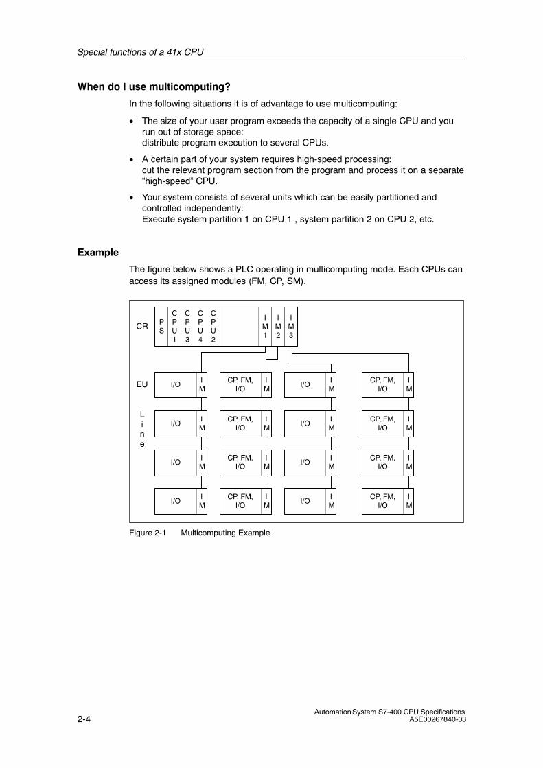
Example
The figure below shows a PLC operating in multicomputing mode. Each CPUs canaccess its assigned modules (FM, CP, SM).
PS
CPU1
CPU3
CPU4
CPU2
IM1
IM2
IM3
IM
I/O
IM
I/O
IM
I/O
IM
I/O
IM
CP, FM,I/O
IM
CP, FM,I/O
IM
CP, FM,I/O
IM
CP, FM,I/O
IM
I/O
IM
I/O
IM
I/O
IM
I/O
IM
CP, FM,I/O
IM
CP, FM,I/O
IM
CP, FM,I/O
IM
CP, FM,I/O
CR
EU
Line
Figure 2-1 Multicomputing Example
Special functions of a 41x CPU
2-5Automation System S7-400 CPU SpecificationsA5E00267840-03
2.2.1 Peculiarities
Slot Rules
In multicomputing operation, up to four CPUs can be inserted at the same time andin any order in a central controller (CC).
Bus Connection
The CPUs are interconnected via the communication bus (K bus). That is, ifconfigured accordingly, all CPUs can be accessed by the PG via MPI interface.
Behavior at Startup and During Operation
During startup, all multicomputing CPUs automatically verify that they can operatein synchronism with each other. Synchronization is only possible if therequirements are satisfied:
• All configured CPUs (but only those) are inserted and fully functional.
• A proper configuration was created in STEP 7 and loaded to all CPUs in therack.
If one of these conditions is not satisfied, an event with the ID 0x49A4 is output tothe diagnostic buffer. For information on event IDs, refer to the reference help forstandard and system functions.
When the CPU exits STOP mode, it compares the startup modes (COLDRESTART/RESTART (WARM RESTART) / HOT RESTART). With differentstartup modes, the CPUs do not switch to RUN mode.
Assignment of Addresses and Interrupts
In multicomputing mode, each CPU can access the modules it was assigned in theSTEP 7 configuration. The address area of a module is always assignedexclusively to one CPU.
Each interrupt-capable module is therefore assigned to a CPU. Interruptsoriginating from such a module can not be received by the other CPUs.
Special functions of a 41x CPU
2-6Automation System S7-400 CPU Specifications
A5E00267840-03
Interrupt Processing
The following applies to interrupt processing:
• Process interrupts and diagnostic interrupts are only sent to one CPU.
• When a module fails or is removed or inserted, the interrupt is processed by theCPU that was assigned to the module in the STEP 7 configuration.Exception: A module insertion/removal interrupt output by a CP reaches all theCPUs, irrespective of the CP having been assigned to a CPU in the STEP 7configuration.
• In the event of a rack failure, OB 86 is called on each CPU, including the CPUswhich were not assigned a module in the faulty rack.
For further information on OB86, refer to the reference help on organization blocks.
I/O application specification
The typical I/O application specification of a PLC corresponds in multicomputingoperation to the typical application specification of the CPU with the mostresources. The relevant CPU-specific or DP master-specific typical applicationspecifications cannot be exceeded in the individual CPUs.
2.2.2 Multicomputing Interrupt
Using the multicomputing interrupt (OB 60), you can respond synchronously to anevent in multicomputing on the corresponding CPUs. In contrast to the processinterrupts triggered by signal modules, the multicomputing interrupt can be outputonly by CPUs. The multicomputing interrupt is triggered by calling SFC 35“MP_ALM“.
You will find more information in the System Software for S7-300/400, System andStandard Functions manual.
2.2.3 Configuring and programming multicomputing operation
Please refer to the manual Configuring Hardware and Communication Connectionswith STEP 7 to find out how to configure and program the CPUs and the modules.
Special functions of a 41x CPU
2-7Automation System S7-400 CPU SpecificationsA5E00267840-03
2.3 Modifications to the System During Operation
Certain changes can be made in the system configuration by means of CiR(Configuration in RUN) while the system is in RUN. Processing is halted for a briefperiod in order to accomplish this. The upper limit of this time period is set to onesecond by default but can be changed. During this time, the process inputs retaintheir most recent value (see the manual, “ Modifications to the System DuringOperation Using CiR”
You can download a free copy of this manual from the Internetaddress:http://www.siemens.com/automation/service&support
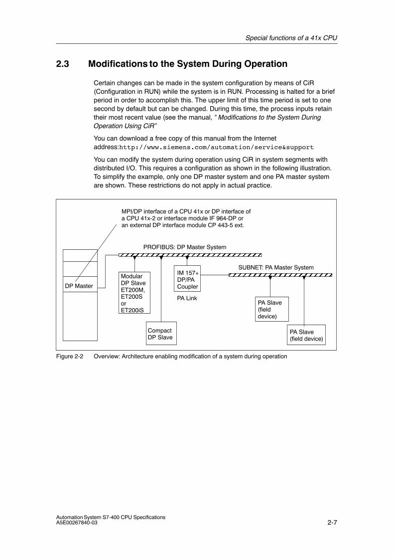
You can modify the system during operation using CiR in system segments withdistributed I/O. This requires a configuration as shown in the following illustration.To simplify the example, only one DP master system and one PA master systemare shown. These restrictions do not apply in actual practice.
ModularDP SlaveET200M,ET200SorET200iS
CompactDP Slave
IM 157+DP/PACoupler
PA Slave(field device)
SUBNET: PA Master System
DP Master
MPI/DP interface of a CPU 41x or DP interface ofa CPU 41x-2 or interface module IF 964-DP oran external DP interface module CP 443-5 ext.
PROFIBUS: DP Master System
PA LinkPA Slave(fielddevice)
Figure 2-2 Overview: Architecture enabling modification of a system during operation
Special functions of a 41x CPU
2-8Automation System S7-400 CPU Specifications
A5E00267840-03
Hardware Requirements for Modification of a System During Operation
The following hardware requirements must have been fulfilled earlier in thecommissioning phase in order to be able to subsequently modify the system duringoperation:
• An S7-400 standard CPU (CPU 412, CPU 414, CPU 416 or CPU 417),firmware V3.1 or later, or an S7-400-H-CPU (CPU 414-4H or CPU 417-4H) insingle mode firmware V3.1 or later.
• If you wish to modify the system during operation on a DP master system withremote DP master (CP 443-5 extended), it must have firmware V5.0 or later.
• If you want to add modules for the ET 200M: Use the IM153-2 versionMLFB 6ES7153-2AA03-0XB0 or later or the IM 153-2FO versionMLFB 6ES7153-2BB00-0XB0 or later. You will also need to install the ET 200Mwith active bus elements and with enough free space for the plannedexpansion. You may not install the ET 200M as DPV0 slave (using a GSD file).
• If you wish to add entire stations: be sure to include the required busconnectors, repeaters, etc.
• If you wish to add PA slaves (field devices): use the IM157 version6ES7157-0AA82-0XA00 or later in the corresponding DP/PA Link.
• The CR2 rack cannot be used.
• CP 444 and IM 467 modules can not be used within a station of which you wantto modify the system configuation data in RUN by means of CiR.
• No multicomputing.
• No clocked operation on the same DP master system.
Note
You can freely mix components that are capable of system modification duringoperation and those that are not (except for the excluded modules, see above).However, you can modify the system configuration of components which arecompatible with CiR.
Special functions of a 41x CPU
2-9Automation System S7-400 CPU SpecificationsA5E00267840-03
Software Requirements for System Modifications During Operation
To be able to change a configuration in RUN mode, the user program must fulfillthe following requirements: it must be written in such a way that station failures,module faults or exceeding cycle times do lead to a CPU STOP.
The following OBs are installed on the CPU:
• Process interrupt OBs (OB 40 to OB 47)
• Time-out error OB (OB 80)
• Diagnostic interrupt OB (OB 82)
• Insertion/removal OB (OB 83)
• CPU hardware error OB (OB 84)
• Runtime error OB (OB 85)
• Rack failure OB (OB 86)
• I/O access error OB (OB 122)
Permitted system modifications during operation: overview
The following modifications can be made to the system during operation:
• Add modules to the modular DP slave ET 200M, provided it has not beenimplemented as DPV0 slave (by means of GSD file)
• Reconfigure ET 200M modules, for example, modifying interrupt limits, or usingthe free channels.
• Use of the free channels of a module, or of a module of the ET 200M, ET 200S,ET 200iS modular slaves.
• Add DP slaves to an existing DP master system.
• Add PA slaves (field devices) to a PA master system
• Install DP/PA couplers downstream of an IM157
• Add PA Links (including PA master systems) to an existing DP master system
• Assign modules o a process image partition
• Reconfigure the modules of ET 200M stations (standard modules and fail-safesignal modules in standard mode).
• Undo modifications: for example, added modules, submodules, DP slaves andPA slaves (field devices) can be removed again.
Note
You can not add or remove slaves or modules, or make changes to a processimage partition, on systems containing more than four DP masters.
Changes in RUN other than those specified earlier are not permitted and areexcluded from this documentation.

Special functions of a 41x CPU
2-10Automation System S7-400 CPU Specifications
A5E00267840-03
3-1Automation System S7-400 CPU SpecificationsA5E00267840-03
S7-400 in PROFIBUS DP mode
Chapter overview
In section You find On Page
3.1 CPU 41x as DP Master/DP Slave 3-2
3.2 Direct Communication 3-31
3.3 Consistent Data 3-34
3
S7-400 in PROFIBUS DP mode
3-2Automation System S7-400 CPU Specifications
A5E00267840-03
3.1 CPU 41x as DP Master/DP Slave
Introduction
This section contains the properties and technical specifications you require forusing a 41x CPU as DP master or DP slave and to configure these for direct dataexchange.
Agreed is: Because of the fact that DP master / DP slave behavior is the same forall CPUs, we refer to the CPUs described below as 41x CPU.
Further reference material
For information on the HW and SW configuration of a PROFIBUS subnet and ondiagnostics functions within the PROFIBUS subnet, refer to the STEP 7Online Help.
S7-400 in PROFIBUS DP mode
3-3Automation System S7-400 CPU SpecificationsA5E00267840-03
3.1.1 DP address areas of 41x CPUs
Address areas of 41x CPUs
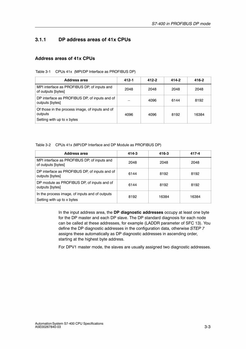
Table 3-1 CPUs 41x (MPI/DP Interface as PROFIBUS DP)
Address area 412-1 412-2 414-2 416-2
MPI interface as PROFIBUS DP, of inputs andof outputs [bytes]
2048 2048 2048 2048
DP interface as PROFIBUS DP, of inputs and ofoutputs [bytes]
– 4096 6144 8192
Of those in the process image, of inputs and ofoutputs
Setting with up to x bytes4096 4096 8192 16384
Table 3-2 CPUs 41x (MPI/DP Interface and DP Module as PROFIBUS DP)
Address area 414-3 416-3 417-4
MPI interface as PROFIBUS DP, of inputs andof outputs [bytes]
2048 2048 2048
DP interface as PROFIBUS DP, of inputs and ofoutputs [bytes]
6144 8192 8192
DP module as PROFIBUS DP, of inputs and ofoutputs [bytes]
6144 8192 8192
In the process image, of inputs and of outputs
Setting with up to x bytes8192 16384 16384
In the input address area, the DP diagnostic addresses occupy at least one bytefor the DP master and each DP slave. The DP standard diagnosis for each nodecan be called at these addresses, for example (LADDR parameter of SFC 13). Youdefine the DP diagnostic addresses in the configuration data, otherwise STEP 7assigns these automatically as DP diagnostic addresses in ascending order,starting at the highest byte address.
For DPV1 master mode, the slaves are usually assigned two diagnostic addresses.
S7-400 in PROFIBUS DP mode
3-4Automation System S7-400 CPU Specifications
A5E00267840-03
3.1.2 41x CPU as PROFIBUS DP master
Introduction
This section provides information on the properties and technical data of a CPUoperating in DP master mode.
Starting with section 6.1, you can find this information for 41x CPUs.
Requirements
You must configure the relevant CPU interface for operation in DP master mode.That is, in STEP 7 you
• Configure the CPU as DP master
• Assign a PROFIBUS address
• Select an operating mode (S7-compatible or DPV1)
• Assign a diagnostic address
• Connect DP slaves to the DP master system
Note
Is one of the PROFIBUS DP slaves a 31x or 41x CPU?
If yes, you will find it in the PROFIBUS DP catalog as a “preconfigured station”.Assign this DP slave CPU a slave diagnostic address in the DP master.Interconnect the DP master with the DP slave, and define the address areas fordata exchange with the DP slave.
From EN 50170 to DPV1 standard
The enhancements of the EN 50170 standard for distributed I/O were incorporatedin IEC 61158 / IEC 61784-1:2002 Ed1 CP 3/1. The SIMATIC documentation refersto these as DPV1. The new version features a few additions and simplifications.
This DPV1 functionality is already implemented on certain SIEMENS automationcomponents. Some slight modifications are required in order to enable this newfunctionality for your system. Information on the migration from EN 50170 to DPV1is available on the Internet, on the FAQ pages “Changing from EN 50170 toDPV1”, FAQ ID 7027576, of the Customer Support.
S7-400 in PROFIBUS DP mode
3-5Automation System S7-400 CPU SpecificationsA5E00267840-03
Components supporting PROFIBUS DPV1 functionality
DPV1 masters
• S7-400 CPUs with integrated DP interface, with firmware V3.0 or higher.
• CP 443-5, order number 6GK7443-5DX03-0XE0, if used with one of theseS7-400 CPUs.
DPV1 slaves
• DP slaves listed under their family name in the STEP 7 hardware catalog canbe identified as DPV1 slave based on the included comment.
• DP slaves integrated in STEP 7 by means of GSD files, GSD Rev. 3 or higher.
STEP 7
STEP 7 V5.1 with Service Pack 2, or a higher version.
What are the operating modes for DPV1 components?
• S7-compatible
In this mode, the components are compatible to EN 50170. Note that you cannot utilize the full DPV1 functionality in this mode.
• DPV1 mode
In this mode, you can utilize the full DPV1 functionality. Incompatibleautomation components in the station can be used as before.
DPV1 and EN 50170 compatibility
You can continue to use all existing slaves after the system conversion to DPV1.These are, however, do not support the enhanced function of DPV1.
DPV1 slaves can be implemented in system which are not converted to DPV1. Inthis case, their behavior corresponds with that of conventional slaves. SIEMENSDPV1 slaves can be operated in S7-compatible mode. For the DPV1 slaves ofexternal manufacturers, you need a GSD file < Rev. 3 file to EN50170.
Migrating to DPV1
The migration to DPV1 applies to the entire station. You can set this DP mode inHW Config in STEP 7.
Further Information
Descriptions and information relating to the migration from PROFIBUS DP toPROFIBUS DPV1 is found on the Internet URL:
http://www.siemens.com/automation/service&support
Refer to ID 7027576
S7-400 in PROFIBUS DP mode
3-6Automation System S7-400 CPU Specifications
A5E00267840-03
Monitor / modify, programming via PROFIBUS
The PROFIBUS DP interface is an alternative to the MPI interface you can use toprogram the CPU or execute the PG functions Monitor and Modify.
Note
The execution of programming and monitor/modify functions via PROFIBUS DPinterface prolongs the DP cycle.
Constant bus cycle time
This is a property of PROFIBUS DP. The “Constant bus cycle time” functionensures that the DP master always starts the DP bus cycle within a constantinterval. From the view of the slaves, this means that they receive their data fromthe master at constant time intervals.
In STEP 7 V 5.2 or higher, you can configure constant bus cycle times forPROFIBUS subnets.
Clocked update of process image partitions
SFC 126 “SYNC_PI“ is used for the clocked update of the process image partitionof inputs. An application program which is interconnected to a DP cycle can usethe SFC for consistent updates of the data recorded in the process image partitionof inputs in synchronism with this cycle. SFC126 accepts interrupt control and canonly be called in the OBs 61, 62, 63 and 64.
SFC 127 “SYNC_PO“ s used for the clocked update of the process image partitionof ouptuts. An application program which is interconnected to a DP cycle can usethe SFC for the consistent transfer of the computed output data of a processimage partition of outputs to the I/O in synchonism with this cycle. SFC127 acceptsinterrupt control and can only be called in the OBs 61, 62, 63 and 64.
To allow clocked updates of process image partitions, all input or output addressesof a slave must be assigned to the same process image partition.
To ensure consistency of data in a process image partition, the following conditionsmust be satisfied on the various CPUs:
• CPU 412: number of slaves + number of bytes / 100 < 16
• CPU 414: number of slaves + number of bytes / 100 < 26
• CPU 416: number of slaves + number of bytes / 100 < 40
• CPU 417: number of slaves + number of bytes / 100 < 44
The SFCs 126 and 127 are descibed in the corresponding Online Help and in the“System and Standard Functions” manual.
S7-400 in PROFIBUS DP mode
3-7Automation System S7-400 CPU SpecificationsA5E00267840-03
Consistent user data
These are data which are associated in context and describe a process status at agiven time. To ensure consistency, these data should not be modified or updatedwhile being processed or transferred.
For details, refer to chapter 3.3.
SYNC/FREEZE
The SYNC control command is used to set sync mode at the DP slaves ofselected groups. That is, the DP master transfers current output data and instructsthe relevant DP slaves to freeze their outputs. The DP slaves writes the outputdata of the next output datagrams to an internal buffer; the state of the outputsremains unchanged.
Following each SYNC control command, the DP slaves of the selected groupstransfer the output data stored in the internal buffer to the process outputs.
The outputs are only updated cyclically again after you transfer the UNSYNCcontrol command using SFC 11 “DPSYC_FR”.
The FREEZE control command is used to set the relavant DP slaves to Freezemode, that is, the DP master instructs the DP slaves to freeze the current state ofthe inputs. It then transfers the frozen data to the input area of the CPU.
Following each FREEZE control command, the DP slaves freeze the state of theirinputs again.
The DP master receives the current state of the inputs cyclically again not until youhave sent the UNFREEZE control command with SFC 11 “DPSYC_FR”.
For information on SFC 11, refer to the corresponding Online Help or to the“System and Standard Functions” manual.
Power-up of the DP master system
Use the following parameters to set power-up monitoring of the DP master:
• Transfer of the parameters to modules
• “Ready” message from the module
In other words, the DP slaves must power up and be configured by the CPU (asDP master) within the set time.
PROFIBUS Address of the DP Master
All PROFIBUS addresses are allowed.
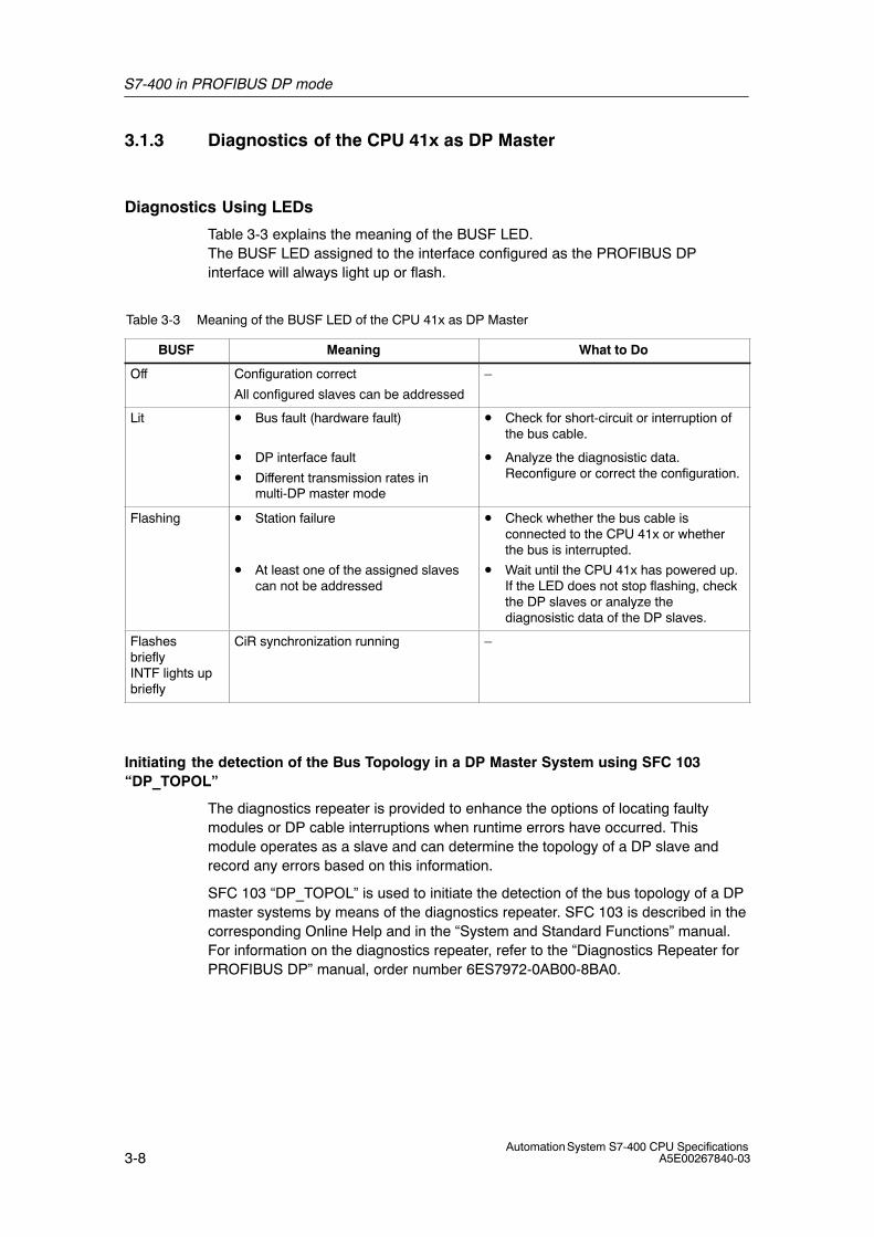
S7-400 in PROFIBUS DP mode
3-8Automation System S7-400 CPU Specifications
A5E00267840-03
3.1.3 Diagnostics of the CPU 41x as DP Master
Diagnostics Using LEDs
Table 3-3 explains the meaning of the BUSF LED.The BUSF LED assigned to the interface configured as the PROFIBUS DPinterface will always light up or flash.
Table 3-3 Meaning of the BUSF LED of the CPU 41x as DP Master
BUSF Meaning What to Do
Off Configuration correct
All configured slaves can be addressed
–
Lit • Bus fault (hardware fault) • Check for short-circuit or interruption ofthe bus cable.
• DP interface fault
• Different transmission rates inmulti-DP master mode
• Analyze the diagnosistic data.Reconfigure or correct the configuration.
Flashing • Station failure
• At least one of the assigned slavescan not be addressed
• Check whether the bus cable isconnected to the CPU 41x or whetherthe bus is interrupted.
• Wait until the CPU 41x has powered up.If the LED does not stop flashing, checkthe DP slaves or analyze thediagnosistic data of the DP slaves.
FlashesbrieflyINTF lights upbriefly
CiR synchronization running –
Initiating the detection of the Bus Topology in a DP Master System using SFC 103“DP_TOPOL”
The diagnostics repeater is provided to enhance the options of locating faultymodules or DP cable interruptions when runtime errors have occurred. Thismodule operates as a slave and can determine the topology of a DP slave andrecord any errors based on this information.
SFC 103 “DP_TOPOL” is used to initiate the detection of the bus topology of a DPmaster systems by means of the diagnostics repeater. SFC 103 is described in thecorresponding Online Help and in the “System and Standard Functions” manual.For information on the diagnostics repeater, refer to the “Diagnostics Repeater forPROFIBUS DP” manual, order number 6ES7972-0AB00-8BA0.
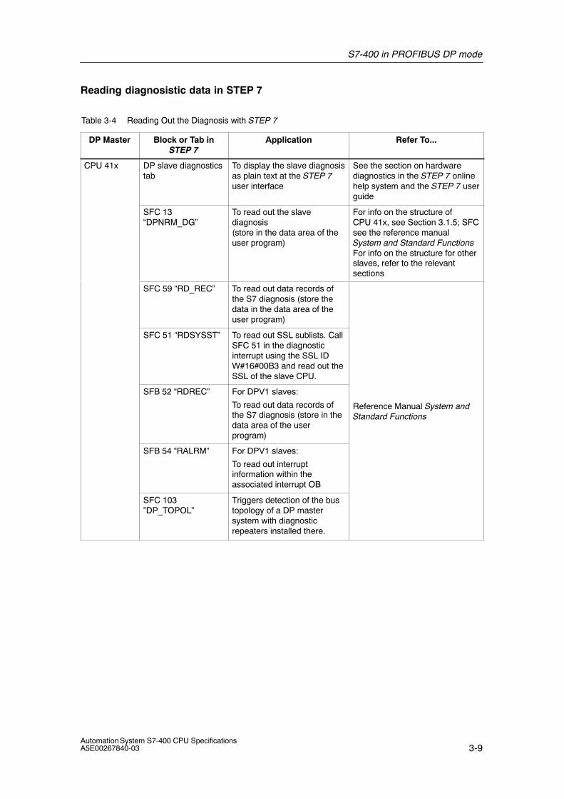
S7-400 in PROFIBUS DP mode
3-9Automation System S7-400 CPU SpecificationsA5E00267840-03
Reading diagnosistic data in STEP 7
Table 3-4 Reading Out the Diagnosis with STEP 7
DP Master Block or Tab inSTEP 7
Application Refer To...
CPU 41x DP slave diagnosticstab
To display the slave diagnosisas plain text at the STEP 7user interface
See the section on hardwarediagnostics in the STEP 7 onlinehelp system and the STEP 7 userguide
SFC 13“DPNRM_DG”
To read out the slavediagnosis(store in the data area of theuser program)
For info on the structure ofCPU 41x, see Section 3.1.5; SFCsee the reference manualSystem and Standard FunctionsFor info on the structure for otherslaves, refer to the relevantsections
SFC 59 “RD_REC” To read out data records ofthe S7 diagnosis (store thedata in the data area of theuser program)
SFC 51 “RDSYSST” To read out SSL sublists. CallSFC 51 in the diagnosticinterrupt using the SSL IDW#16#00B3 and read out theSSL of the slave CPU.
SFB 52 “RDREC” For DPV1 slaves:
To read out data records ofthe S7 diagnosis (store in thedata area of the userprogram)
Reference Manual System andStandard Functions
SFB 54 “RALRM” For DPV1 slaves:
To read out interruptinformation within theassociated interrupt OB
SFC 103 ”DP_TOPOL”
Triggers detection of the bustopology of a DP mastersystem with diagnosticrepeaters installed there.
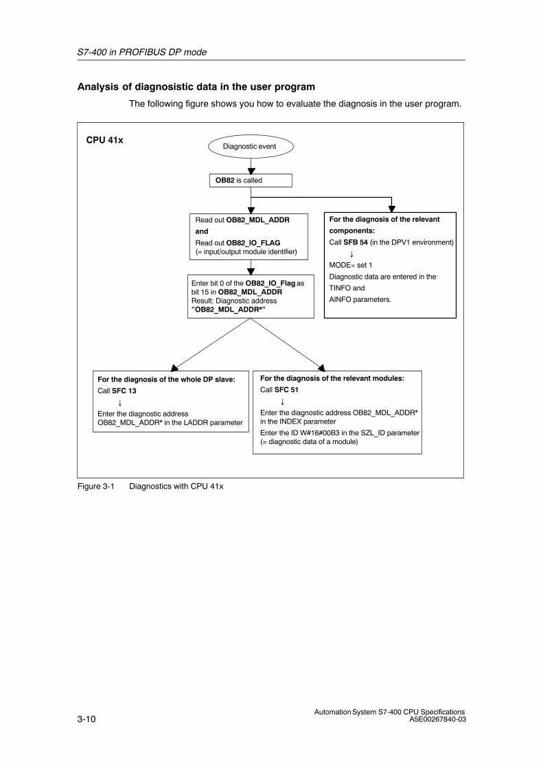
S7-400 in PROFIBUS DP mode
3-10Automation System S7-400 CPU Specifications
A5E00267840-03
Analysis of diagnosistic data in the user program
The following figure shows you how to evaluate the diagnosis in the user program.
Diagnostic event
Read out OB82_MDL_ADDR
and
Read out OB82_IO_FLAG(= input/output module identifier)
For the diagnosis of the whole DP slave:
Call SFC 13
�
Enter the diagnostic addressOB82_MDL_ADDR* in the LADDR parameter
Enter bit 0 of the OB82_IO_Flag asbit 15 in OB82_MDL_ADDRResult: Diagnostic address”OB82_MDL_ADDR*”
For the diagnosis of the relevant modules:
Call SFC 51
�
Enter the diagnostic address OB82_MDL_ADDR*in the INDEX parameter
Enter the ID W#16#00B3 in the SZL_ID parameter(= diagnostic data of a module)
CPU 41x
OB82 is called
For the diagnosis of the relevant
components:
Call SFB 54 (in the DPV1 environment)
�
MODE= set 1
Diagnostic data are entered in the
TINFO and
AINFO parameters.
Figure 3-1 Diagnostics with CPU 41x
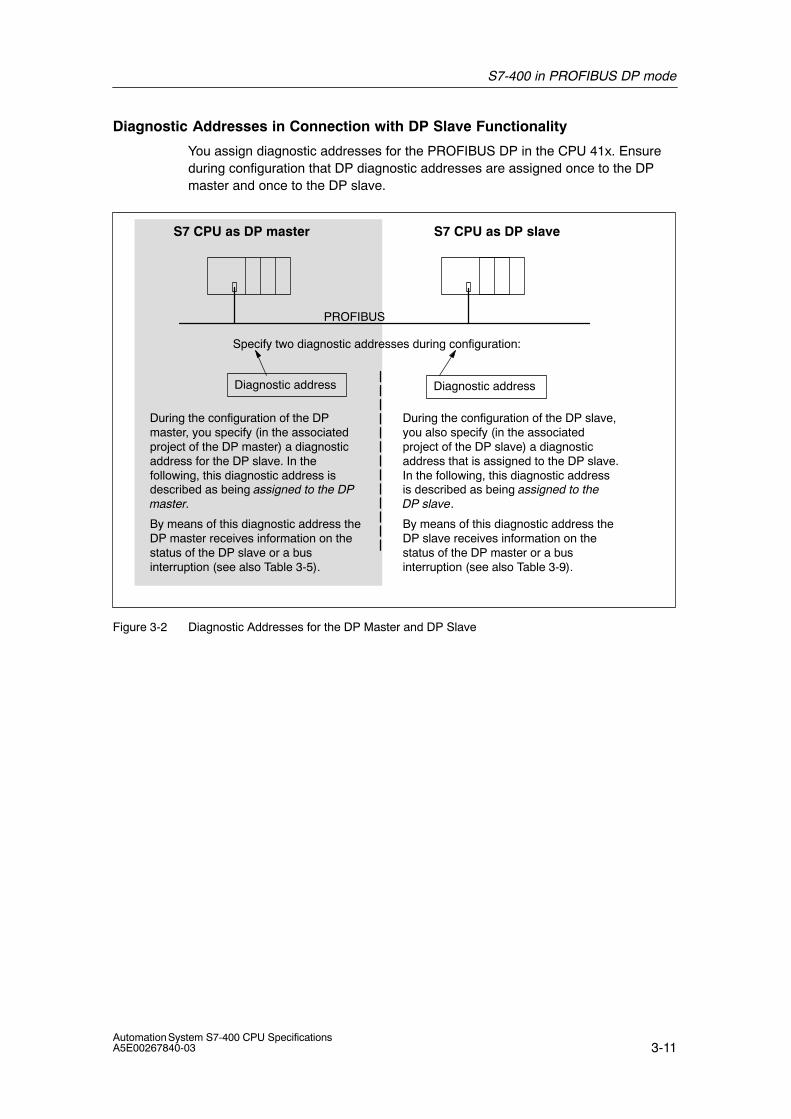
S7-400 in PROFIBUS DP mode
3-11Automation System S7-400 CPU SpecificationsA5E00267840-03
Diagnostic Addresses in Connection with DP Slave Functionality
You assign diagnostic addresses for the PROFIBUS DP in the CPU 41x. Ensureduring configuration that DP diagnostic addresses are assigned once to the DPmaster and once to the DP slave.
Specify two diagnostic addresses during configuration:
PROFIBUS
S7 CPU as DP slaveS7 CPU as DP master
Diagnostic address Diagnostic address
During the configuration of the DPmaster, you specify (in the associatedproject of the DP master) a diagnosticaddress for the DP slave. In thefollowing, this diagnostic address isdescribed as being assigned to the DPmaster.
During the configuration of the DP slave,you also specify (in the associatedproject of the DP slave) a diagnosticaddress that is assigned to the DP slave.In the following, this diagnostic addressis described as being assigned to theDP slave.
By means of this diagnostic address theDP master receives information on thestatus of the DP slave or a businterruption (see also Table 3-5).
By means of this diagnostic address theDP slave receives information on thestatus of the DP master or a businterruption (see also Table 3-9).
Figure 3-2 Diagnostic Addresses for the DP Master and DP Slave
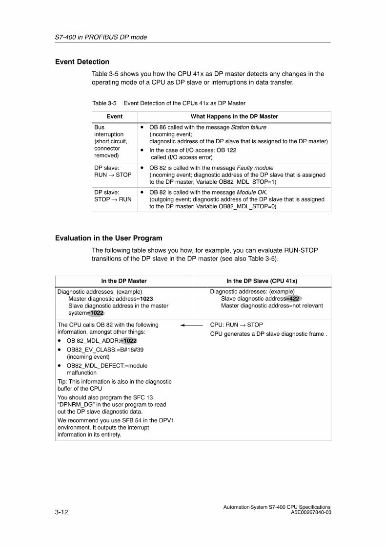
S7-400 in PROFIBUS DP mode
3-12Automation System S7-400 CPU Specifications
A5E00267840-03
Event Detection
Table 3-5 shows you how the CPU 41x as DP master detects any changes in theoperating mode of a CPU as DP slave or interruptions in data transfer.
Table 3-5 Event Detection of the CPUs 41x as DP Master
Event What Happens in the DP Master
Businterruption(short circuit,connectorremoved)
• OB 86 called with the message Station failure (incoming event; diagnostic address of the DP slave that is assigned to the DP master)
• In the case of I/O access: OB 122 called (I/O access error)
DP slave: RUN → STOP
• OB 82 is called with the message Faulty module(incoming event; diagnostic address of the DP slave that is assignedto the DP master; Variable OB82_MDL_STOP=1)
DP slave: STOP → RUN
• OB 82 is called with the message Module OK.(outgoing event; diagnostic address of the DP slave that is assignedto the DP master; Variable OB82_MDL_STOP=0)
Evaluation in the User Program
The following table shows you how, for example, you can evaluate RUN-STOPtransitions of the DP slave in the DP master (see also Table 3-5).
In the DP Master In the DP Slave (CPU 41x)
Diagnostic addresses: (example)Master diagnostic address=1023Slave diagnostic address in the mastersystem=1022
Diagnostic addresses: (example)Slave diagnostic address=422Master diagnostic address=not relevant
The CPU calls OB 82 with the followinginformation, amongst other things:
• OB 82_MDL_ADDR:=1022
• OB82_EV_CLASS:=B#16#39(incoming event)
• OB82_MDL_DEFECT:=modulemalfunction
Tip: This information is also in the diagnosticbuffer of the CPU
You should also program the SFC 13“DPNRM_DG” in the user program to readout the DP slave diagnostic data.
We recommend you use SFB 54 in the DPV1environment. It outputs the interruptinformation in its entirety.
CPU: RUN → STOP
CPU generates a DP slave diagnostic frame .
S7-400 in PROFIBUS DP mode
3-13Automation System S7-400 CPU SpecificationsA5E00267840-03
3.1.4 CPU 41x as DP Slave
Introduction
In this section we describe the features and technical specifications of the CPU ifyou operate it as a DP slave.
You can find the features and technical specifications of the CPUs 41x as of Section 6.1.
Requirements
1. Only one DP interface of a CPU can be configured as a DP slave.
2. Is the MPI/DP interface to be a DP interface? If so, you must configure theinterface as a DP interface.
Before commissioning you must configure the CPU as a DP slave. In otherwords, you must do the following in STEP 7
– Activate the CPU as a DP slave
– Assign a PROFIBUS address
– Assign a slave diagnostic address
– Define the address areas for data transfer to the DP master
GSD Files
You need a DDB file to configure the CPU as a DP slave in a third-party system.
You can download the GSD file free of charge from the Internet athttp://www.ad.siemens.de/csi_e/gsd.
You can also download the GSD file from the mailbox of the Interface Center inFürth on +49 (911) 737972.
Configuration and Parameter Assignment Frame
When you configure and assign parameters to CPU 41x, you are supported bySTEP 7. If you require a description of the configuration and parameter assignmentframe to carry out a check with a bus monitor, for example, you will find it on theInternet at http://www.ad.siemens.de/simatic-cs under the ID 1452338
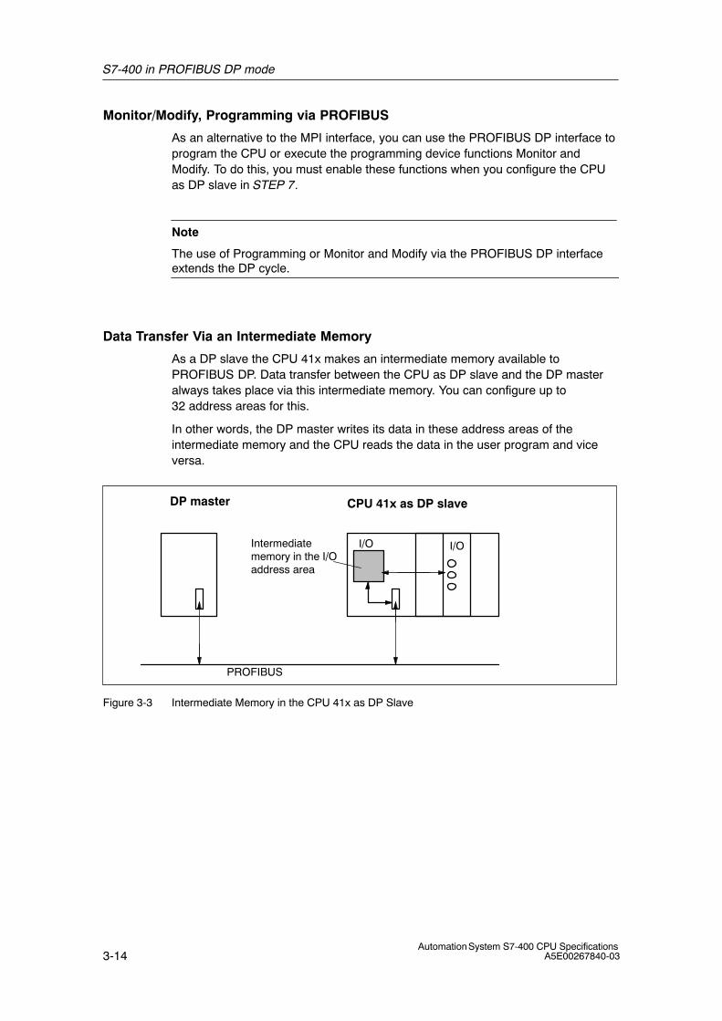
S7-400 in PROFIBUS DP mode
3-14Automation System S7-400 CPU Specifications
A5E00267840-03
Monitor/Modify, Programming via PROFIBUS
As an alternative to the MPI interface, you can use the PROFIBUS DP interface toprogram the CPU or execute the programming device functions Monitor andModify. To do this, you must enable these functions when you configure the CPUas DP slave in STEP 7.
Note
The use of Programming or Monitor and Modify via the PROFIBUS DP interfaceextends the DP cycle.
Data Transfer Via an Intermediate Memory
As a DP slave the CPU 41x makes an intermediate memory available toPROFIBUS DP. Data transfer between the CPU as DP slave and the DP masteralways takes place via this intermediate memory. You can configure up to32 address areas for this.
In other words, the DP master writes its data in these address areas of theintermediate memory and the CPU reads the data in the user program and viceversa.
Intermediatememory in the I/Oaddress area
PROFIBUS
I/O
CPU 41x as DP slaveDP master
I/O
Figure 3-3 Intermediate Memory in the CPU 41x as DP Slave
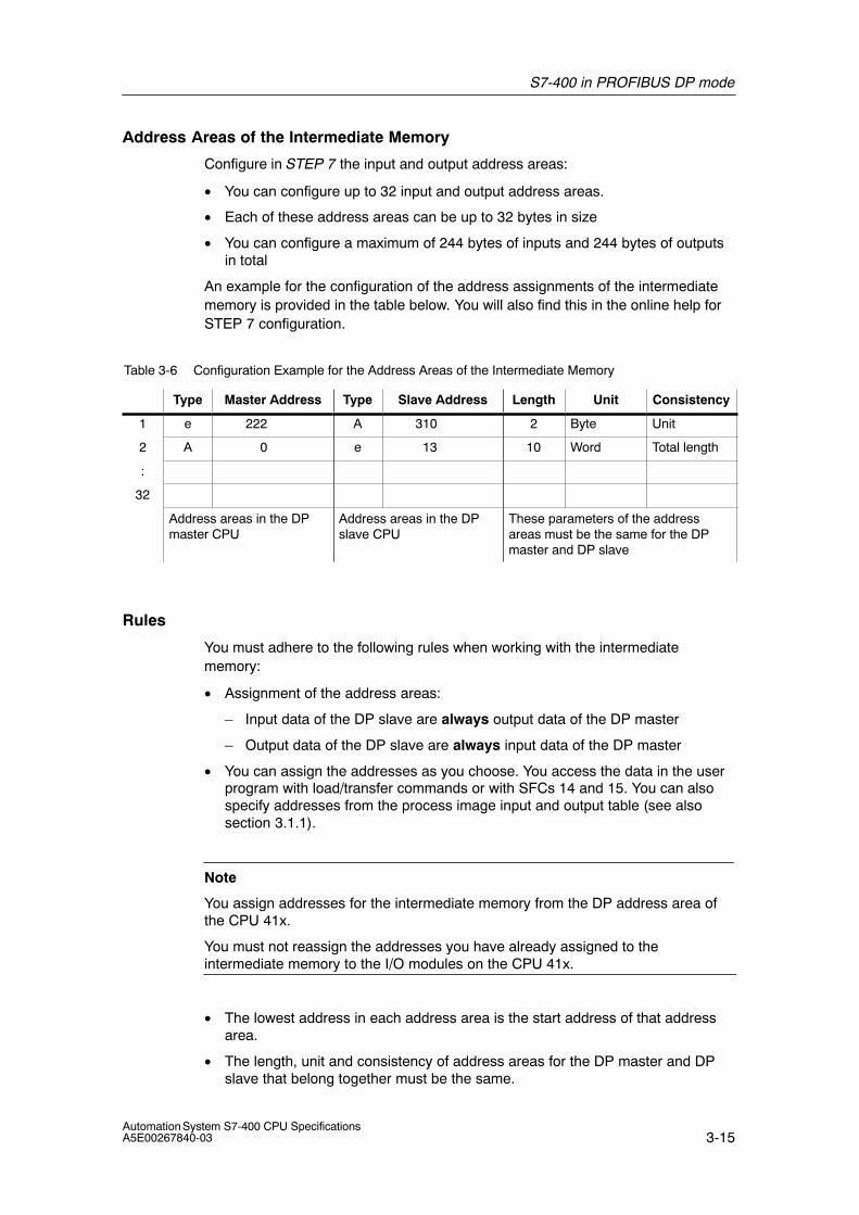
S7-400 in PROFIBUS DP mode
3-15Automation System S7-400 CPU SpecificationsA5E00267840-03
Address Areas of the Intermediate Memory
Configure in STEP 7 the input and output address areas:
• You can configure up to 32 input and output address areas.
• Each of these address areas can be up to 32 bytes in size
• You can configure a maximum of 244 bytes of inputs and 244 bytes of outputsin total
An example for the configuration of the address assignments of the intermediatememory is provided in the table below. You will also find this in the online help forSTEP 7 configuration.
Table 3-6 Configuration Example for the Address Areas of the Intermediate Memory
Type Master Address Type Slave Address Length Unit Consistency
1 e 222 A 310 2 Byte Unit
2 A 0 e 13 10 Word Total length
:
32
Address areas in the DPmaster CPU
Address areas in the DPslave CPU
These parameters of the addressareas must be the same for the DPmaster and DP slave
Rules
You must adhere to the following rules when working with the intermediatememory:
• Assignment of the address areas:
– Input data of the DP slave are always output data of the DP master
– Output data of the DP slave are always input data of the DP master
• You can assign the addresses as you choose. You access the data in the userprogram with load/transfer commands or with SFCs 14 and 15. You can alsospecify addresses from the process image input and output table (see alsosection 3.1.1).
Note
You assign addresses for the intermediate memory from the DP address area ofthe CPU 41x.
You must not reassign the addresses you have already assigned to theintermediate memory to the I/O modules on the CPU 41x.
• The lowest address in each address area is the start address of that addressarea.
• The length, unit and consistency of address areas for the DP master and DPslave that belong together must be the same.
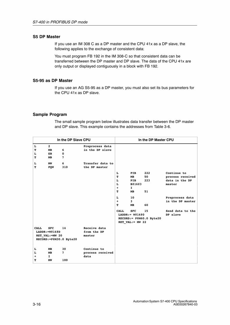
S7-400 in PROFIBUS DP mode
3-16Automation System S7-400 CPU Specifications
A5E00267840-03
S5 DP Master
If you use an IM 308 C as a DP master and the CPU 41x as a DP slave, thefollowing applies to the exchange of consistent data:
You must program FB 192 in the IM 308-C so that consistent data can betransferred between the DP master and DP slave. The data of the CPU 41x areonly output or displayed contiguously in a block with FB 192.
S5-95 as DP Master
If you use an AG S5-95 as a DP master, you must also set its bus parameters forthe CPU 41x as DP slave.
Sample Program
The small sample program below illustrates data transfer between the DP masterand DP slave. This example contains the addresses from Table 3-6.
In the DP Slave CPU In the DP Master CPU
L 2T MB 6L EB 0T MB 7
Preprocess datain the DP slave
L MW 6T PQW 310
Transfer data tothe DP master
L PIB 222T MB 50L PIB 223L B#16#3+ IT MB 51
Continue toprocess receiveddata in the DPmaster
L 10+ 3T MB 60
Preprocess datain the DP master
CALL SFC 15 LADDR:= W#16#0 RECORD:= P#M60.0 Byte20 RET_VAL:= MW 22
Send data to theDP slave
CALL SFC 14 LADDR:=W#16#D RET_VAL:=MW 20 RECORD:=P#M30.0 Byte20
Receive datafrom the DPmaster
L MB 30L MB 7+ IT MW 100
Continue toprocess receiveddata
S7-400 in PROFIBUS DP mode
3-17Automation System S7-400 CPU SpecificationsA5E00267840-03
Data Transfer in STOP Mode
The DP slave CPU goes into STOP mode: The data in the intermediate memory ofthe CPU are overwritten with “0”. In other words, the DP master reads “0”.
The DP master goes into STOP mode: The current data in the intermediatememory of the CPU are retained and can continue to be read by the CPU.
PROFIBUS Address
You cannot set 126 as PROFIBUS address for the CPU 41x as DP slave.
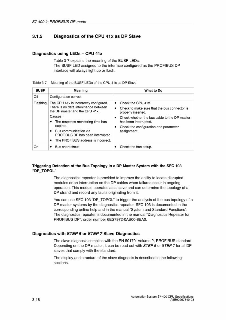
S7-400 in PROFIBUS DP mode
3-18Automation System S7-400 CPU Specifications
A5E00267840-03
3.1.5 Diagnostics of the CPU 41x as DP Slave
Diagnostics using LEDs – CPU 41x
Table 3-7 explains the meaning of the BUSF LEDs.The BUSF LED assigned to the interface configured as the PROFIBUS DPinterface will always light up or flash.
Table 3-7 Meaning of the BUSF LEDs of the CPU 41x as DP Slave
BUSF Meaning What to Do
Off Configuration correct –
Flashing The CPU 41x is incorrectly configured.There is no data interchange betweenthe DP master and the CPU 41x.
Causes:
• The response monitoring time has
• Check the CPU 41x.
• Check to make sure that the bus connector isproperly inserted.
• Check whether the bus cable to the DP masterhas been interrupted• The response monitoring time has
expired.
• Bus communication viaPROFIBUS DP has been interrupted.
• The PROFIBUS address is incorrect.
has been interrupted.
• Check the configuration and parameterassignment.
On • Bus short circuit • Check the bus setupOn • Bus short circuit • Check the bus setup.
Triggering Detection of the Bus Topology in a DP Master System with the SFC 103“DP_TOPOL”
The diagnostics repeater is provided to improve the ability to locate disruptedmodules or an interruption on the DP cables when failures occur in ongoingoperation. This module operates as a slave and can determine the topology of aDP strand and record any faults originating from it.
You can use SFC 103 “DP_TOPOL” to trigger the analysis of the bus topology of aDP master systems by the diagnostics repeater. SFC 103 is documented in thecorresponding online help and in the manual “System and Standard Functions”.The diagnostics repeater is documented in the manual “Diagnostics Repeater forPROFIBUS DP”, order number 6ES7972-0AB00-8BA0.
Diagnostics with STEP 5 or STEP 7 Slave Diagnostics
The slave diagnosis complies with the EN 50170, Volume 2, PROFIBUS standard.Depending on the DP master, it can be read out with STEP 5 or STEP 7 for all DPslaves that comply with the standard.
The display and structure of the slave diagnosis is described in the followingsections.
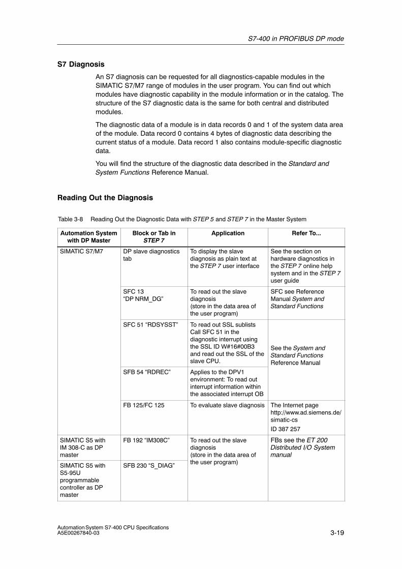
S7-400 in PROFIBUS DP mode
3-19Automation System S7-400 CPU SpecificationsA5E00267840-03
S7 Diagnosis
An S7 diagnosis can be requested for all diagnostics-capable modules in theSIMATIC S7/M7 range of modules in the user program. You can find out whichmodules have diagnostic capability in the module information or in the catalog. Thestructure of the S7 diagnostic data is the same for both central and distributedmodules.
The diagnostic data of a module is in data records 0 and 1 of the system data areaof the module. Data record 0 contains 4 bytes of diagnostic data describing thecurrent status of a module. Data record 1 also contains module-specific diagnosticdata.
You will find the structure of the diagnostic data described in the Standard andSystem Functions Reference Manual.
Reading Out the Diagnosis
Table 3-8 Reading Out the Diagnostic Data with STEP 5 and STEP 7 in the Master System
Automation Systemwith DP Master
Block or Tab inSTEP 7
Application Refer To...
SIMATIC S7/M7 DP slave diagnosticstab
To display the slavediagnosis as plain text atthe STEP 7 user interface
See the section onhardware diagnostics inthe STEP 7 online helpsystem and in the STEP 7user guide
SFC 13“DP NRM_DG”
To read out the slavediagnosis(store in the data area ofthe user program)
SFC see ReferenceManual System andStandard Functions
SFC 51 “RDSYSST” To read out SSL sublistsCall SFC 51 in thediagnostic interrupt usingthe SSL ID W#16#00B3and read out the SSL of theslave CPU.
See the System andStandard FunctionsReference Manual
SFB 54 “RDREC” Applies to the DPV1environment: To read outinterrupt information withinthe associated interrupt OB
Reference Manual
FB 125/FC 125 To evaluate slave diagnosis The Internet pagehttp://www.ad.siemens.de/simatic-cs
ID 387 257
SIMATIC S5 withIM 308-C as DPmaster
FB 192 “IM308C” To read out the slavediagnosis(store in the data area ofth )
FBs see the ET 200Distributed I/O Systemmanual
SIMATIC S5 withS5-95Uprogrammablecontroller as DPmaster
SFB 230 “S_DIAG” the user program)
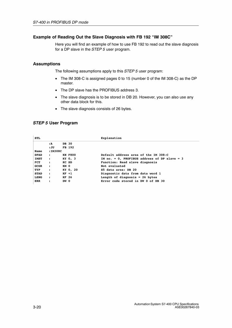
S7-400 in PROFIBUS DP mode
3-20Automation System S7-400 CPU Specifications
A5E00267840-03
Example of Reading Out the Slave Diagnosis with FB 192 “IM 308C”
Here you will find an example of how to use FB 192 to read out the slave diagnosisfor a DP slave in the STEP 5 user program.
Assumptions
The following assumptions apply to this STEP 5 user program:
• The IM 308-C is assigned pages 0 to 15 (number 0 of the IM 308-C) as the DPmaster.
• The DP slave has the PROFIBUS address 3.
• The slave diagnosis is to be stored in DB 20. However, you can also use anyother data block for this.
• The slave diagnosis consists of 26 bytes.
STEP 5 User Program
STL Explanation
:A DB 30:JU FB 192
Name :IM308CDPAD : KH F800IMST : KY 0, 3FCT : KC SDGCGR : KM 0TYP : KY 0, 20STAD : KF +1LENG : KF 26ERR : DW 0
Default address area of the IM 308-CIM no. = 0, PROFIBUS address of DP slave = 3Function: Read slave diagnosisNot evaluatedS5 data area: DB 20Diagnostic data from data word 1Length of diagnosis = 26 bytesError code stored in DW 0 of DB 30
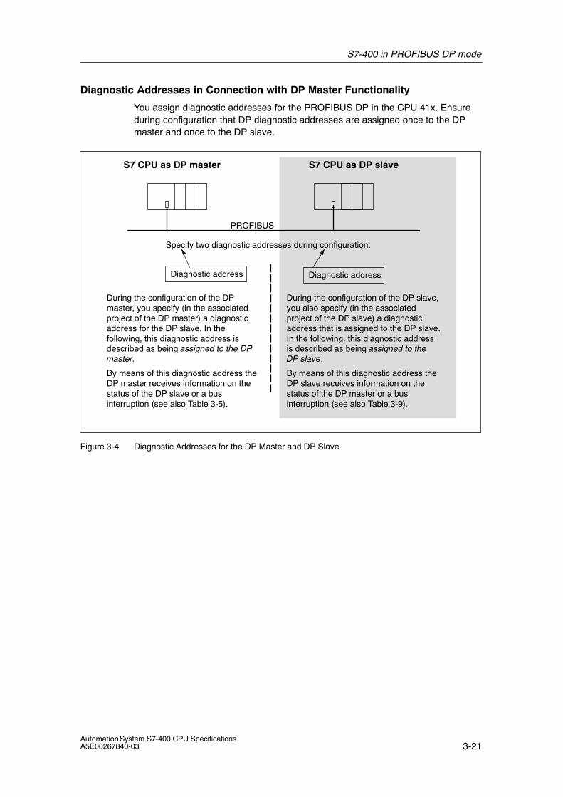
S7-400 in PROFIBUS DP mode
3-21Automation System S7-400 CPU SpecificationsA5E00267840-03
Diagnostic Addresses in Connection with DP Master Functionality
You assign diagnostic addresses for the PROFIBUS DP in the CPU 41x. Ensureduring configuration that DP diagnostic addresses are assigned once to the DPmaster and once to the DP slave.
Specify two diagnostic addresses during configuration:
PROFIBUS
S7 CPU as DP slaveS7 CPU as DP master
Diagnostic address Diagnostic address
During the configuration of the DPmaster, you specify (in the associatedproject of the DP master) a diagnosticaddress for the DP slave. In thefollowing, this diagnostic address isdescribed as being assigned to the DPmaster.
During the configuration of the DP slave,you also specify (in the associatedproject of the DP slave) a diagnosticaddress that is assigned to the DP slave.In the following, this diagnostic addressis described as being assigned to theDP slave.
By means of this diagnostic address theDP master receives information on thestatus of the DP slave or a businterruption (see also Table 3-5).
By means of this diagnostic address theDP slave receives information on thestatus of the DP master or a businterruption (see also Table 3-9).
Figure 3-4 Diagnostic Addresses for the DP Master and DP Slave
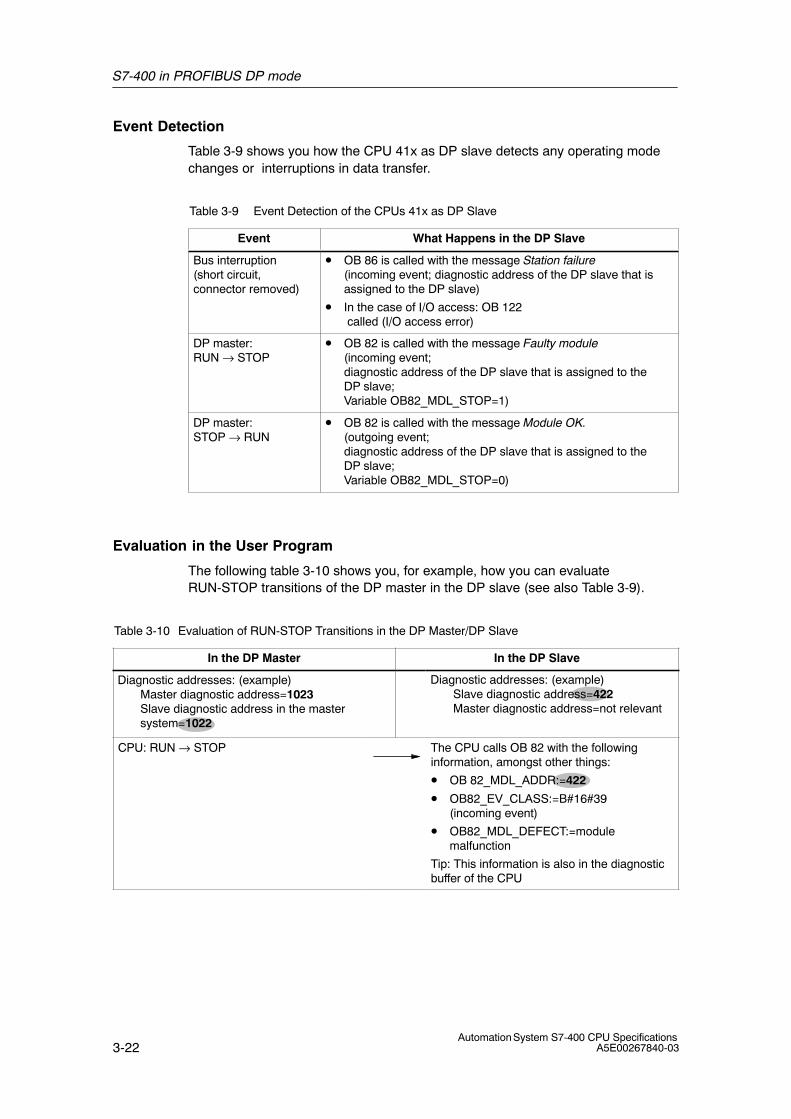
S7-400 in PROFIBUS DP mode
3-22Automation System S7-400 CPU Specifications
A5E00267840-03
Event Detection
Table 3-9 shows you how the CPU 41x as DP slave detects any operating modechanges or interruptions in data transfer.
Table 3-9 Event Detection of the CPUs 41x as DP Slave
Event What Happens in the DP Slave
Bus interruption(short circuit,connector removed)
• OB 86 is called with the message Station failure (incoming event; diagnostic address of the DP slave that isassigned to the DP slave)
• In the case of I/O access: OB 122 called (I/O access error)
DP master: RUN → STOP
• OB 82 is called with the message Faulty module(incoming event; diagnostic address of the DP slave that is assigned to theDP slave; Variable OB82_MDL_STOP=1)
DP master: STOP → RUN
• OB 82 is called with the message Module OK.(outgoing event; diagnostic address of the DP slave that is assigned to theDP slave; Variable OB82_MDL_STOP=0)
Evaluation in the User Program
The following table 3-10 shows you, for example, how you can evaluateRUN-STOP transitions of the DP master in the DP slave (see also Table 3-9).
Table 3-10 Evaluation of RUN-STOP Transitions in the DP Master/DP Slave
In the DP Master In the DP Slave
Diagnostic addresses: (example)Master diagnostic address=1023Slave diagnostic address in the mastersystem=1022
Diagnostic addresses: (example)Slave diagnostic address=422Master diagnostic address=not relevant
CPU: RUN → STOP The CPU calls OB 82 with the followinginformation, amongst other things:
• OB 82_MDL_ADDR:=422
• OB82_EV_CLASS:=B#16#39(incoming event)
• OB82_MDL_DEFECT:=modulemalfunction
Tip: This information is also in the diagnosticbuffer of the CPU
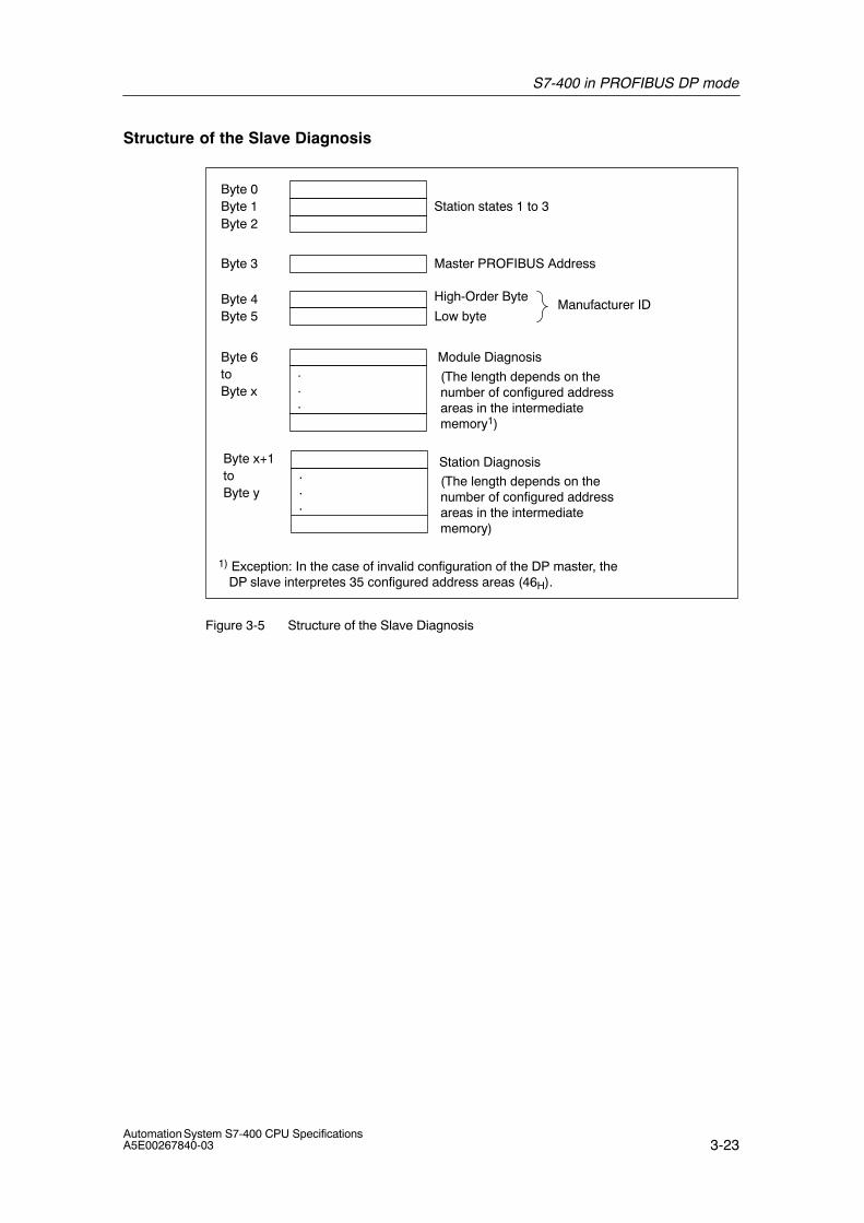
S7-400 in PROFIBUS DP mode
3-23Automation System S7-400 CPU SpecificationsA5E00267840-03
Structure of the Slave Diagnosis
Byte 0Byte 1 Station states 1 to 3Byte 2
Byte 3 Master PROFIBUS Address
Byte 4Byte 5 Low byte
High-Order ByteManufacturer ID
Byte 6to
Module Diagnosis
Byte x
Station Diagnosis...
.
.
.
Byte x+1toByte y
(The length depends on thenumber of configured addressareas in the intermediatememory1)
(The length depends on thenumber of configured addressareas in the intermediatememory)
1) Exception: In the case of invalid configuration of the DP master, the DP slave interpretes 35 configured address areas (46H).
Figure 3-5 Structure of the Slave Diagnosis
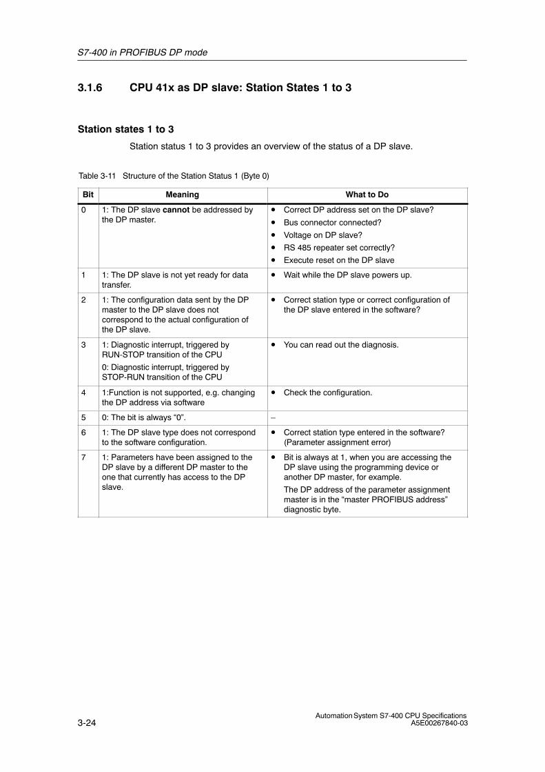
S7-400 in PROFIBUS DP mode
3-24Automation System S7-400 CPU Specifications
A5E00267840-03
3.1.6 CPU 41x as DP slave: Station States 1 to 3
Station states 1 to 3
Station status 1 to 3 provides an overview of the status of a DP slave.
Table 3-11 Structure of the Station Status 1 (Byte 0)
Bit Meaning What to Do
0 1: The DP slave cannot be addressed bythe DP master.
• Correct DP address set on the DP slave?
• Bus connector connected?
• Voltage on DP slave?
• RS 485 repeater set correctly?
• Execute reset on the DP slave
1 1: The DP slave is not yet ready for datatransfer.
• Wait while the DP slave powers up.
2 1: The configuration data sent by the DPmaster to the DP slave does notcorrespond to the actual configuration ofthe DP slave.
• Correct station type or correct configuration ofthe DP slave entered in the software?
3 1: Diagnostic interrupt, triggered byRUN-STOP transition of the CPU
0: Diagnostic interrupt, triggered bySTOP-RUN transition of the CPU
• You can read out the diagnosis.
4 1:Function is not supported, e.g. changingthe DP address via software
• Check the configuration.
5 0: The bit is always “0”. –
6 1: The DP slave type does not correspondto the software configuration.
• Correct station type entered in the software?(Parameter assignment error)
7 1: Parameters have been assigned to theDP slave by a different DP master to theone that currently has access to the DPslave.
• Bit is always at 1, when you are accessing theDP slave using the programming device oranother DP master, for example.
The DP address of the parameter assignmentmaster is in the “master PROFIBUS address”diagnostic byte.
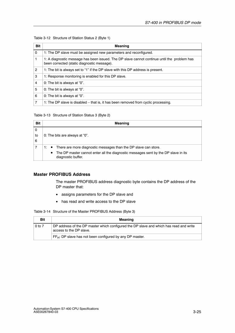
S7-400 in PROFIBUS DP mode
3-25Automation System S7-400 CPU SpecificationsA5E00267840-03
Table 3-12 Structure of Station Status 2 (Byte 1)
Bit Meaning
0 1: The DP slave must be assigned new parameters and reconfigured.
1 1: A diagnostic message has been issued. The DP slave cannot continue until the problem hasbeen corrected (static diagnostic message).
2 1: The bit is always set to “1” if the DP slave with this DP address is present.
3 1: Response monitoring is enabled for this DP slave.
4 0: The bit is always at “0”.
5 0: The bit is always at “0”.
6 0: The bit is always at “0”.
7 1: The DP slave is disabled – that is, it has been removed from cyclic processing.
Table 3-13 Structure of Station Status 3 (Byte 2)
Bit Meaning
0
to
6
0: The bits are always at “0”.
7 1: • There are more diagnostic messages than the DP slave can store.
• The DP master cannot enter all the diagnostic messages sent by the DP slave in itsdiagnostic buffer.
Master PROFIBUS Address
The master PROFIBUS address diagnostic byte contains the DP address of theDP master that:
• assigns parameters for the DP slave and
• has read and write access to the DP slave
Table 3-14 Structure of the Master PROFIBUS Address (Byte 3)
Bit Meaning
0 to 7 DP address of the DP master which configured the DP slave and which has read and writeaccess to the DP slave.
FFH: DP slave has not been configured by any DP master.
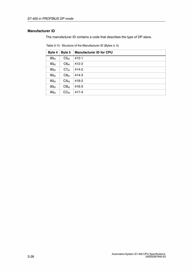
S7-400 in PROFIBUS DP mode
3-26Automation System S7-400 CPU Specifications
A5E00267840-03
Manufacturer ID
The manufacturer ID contains a code that describes the type of DP slave.
Table 3-15 Structure of the Manufacturer ID (Bytes 4, 5)
Byte 4 Byte 5 Manufacturer ID for CPU
80H C5H 412-1
80H C6H 412-2
80H C7H 414-2
80H C8H 414-3
80H CAH 416-2
80H CBH 416-3
80H CCH 417-4
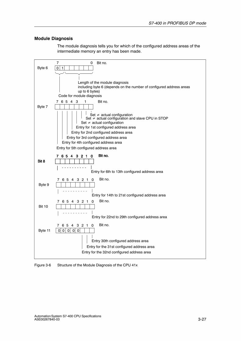
S7-400 in PROFIBUS DP mode
3-27Automation System S7-400 CPU SpecificationsA5E00267840-03
Module Diagnosis
The module diagnosis tells you for which of the configured address areas of theintermediate memory an entry has been made.
Byte 67 0 Bit no.
Length of the module diagnosis including byte 6 (depends on the number of configured address areasup to 6 bytes)
Byte 7
Set � actual configuration and slave CPU in STOP
Entry for 2nd configured address areaEntry for 3rd configured address area
Entry for 4th configured address area
Entry for 5th configured address area
Bit 8
Entry for 6th to 13th configured address area
Code for module diagnosis
0 1
7 6 5 4 1
02 1
3
Entry for 1st configured address area
Bit no.
Bit no.7 6 5 4 3
Byte 11
Entry 30th configured address area
Entry for the 31st configured address area
02 1 Bit no.7 6 5 4 3
Bit 802 1 Bit no.7 6 5 4 3
Bit 802 1 Bit no.7 6 5 4 3
Byte 9
Entry for 14th to 21st configured address area
02 1 Bit no.7 6 5 4 3
Bit 10
Entry for 22nd to 29th configured address area
02 1 Bit no.7 6 5 4 3
Entry for the 32nd configured address area
00 00 0
Set � actual configuration
Set � actual configuration
Figure 3-6 Structure of the Module Diagnosis of the CPU 41x
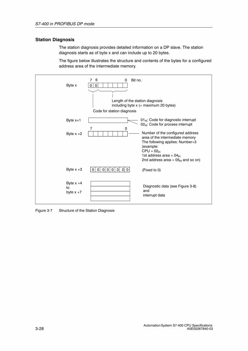
S7-400 in PROFIBUS DP mode
3-28Automation System S7-400 CPU Specifications
A5E00267840-03
Station Diagnosis
The station diagnosis provides detailed information on a DP slave. The stationdiagnosis starts as of byte x and can include up to 20 bytes.
The figure below illustrates the structure and contents of the bytes for a configuredaddress area of the intermediate memory.
Byte x+1 01H: Code for diagnostic interrupt02H: Code for process interrupt
Byte x +4tobyte x +7
Byte x7 0 Bit no.
Length of the station diagnosis including byte x (= maximum 20 bytes)
Code for station diagnosis
0 0
6
Byte x +2
Byte x +3
Number of the configured addressarea of the intermediate memoryThe following applies: Number+3(example:CPU = 02H1st address area = 04H2nd address area = 05H and so on)
(Fixed to 0)
Diagnostic data (see Figure 3-8)andinterrupt data
7 0
0 0 0 0 0 0 0 0
Figure 3-7 Structure of the Station Diagnosis
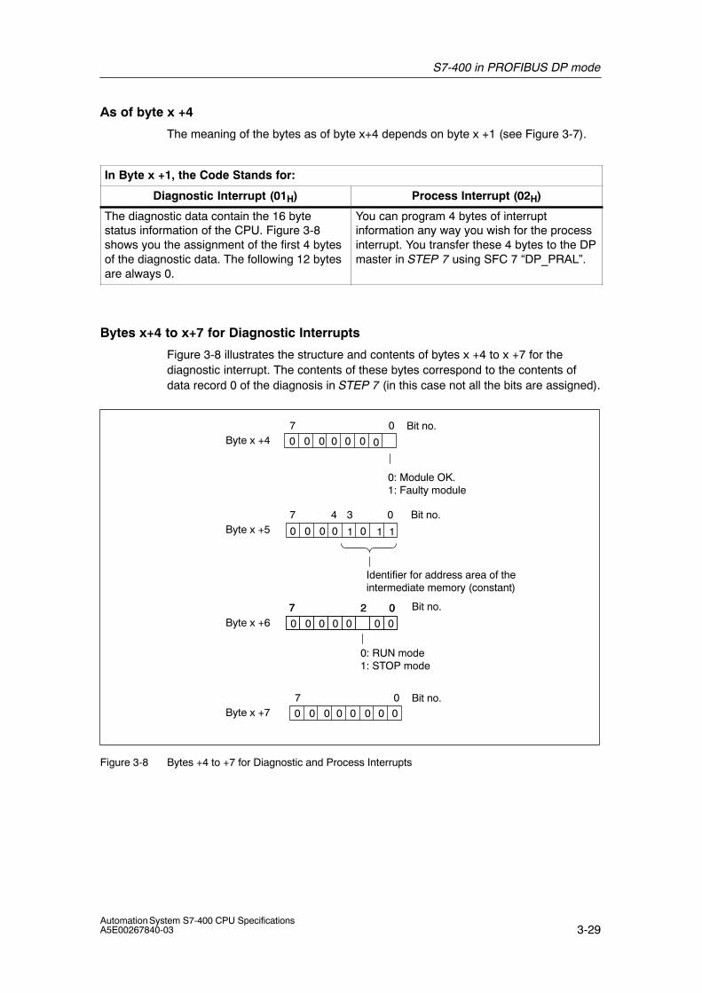
S7-400 in PROFIBUS DP mode
3-29Automation System S7-400 CPU SpecificationsA5E00267840-03
As of byte x +4
The meaning of the bytes as of byte x+4 depends on byte x +1 (see Figure 3-7).
In Byte x +1, the Code Stands for:
Diagnostic Interrupt (01H) Process Interrupt (02H)
The diagnostic data contain the 16 bytestatus information of the CPU. Figure 3-8shows you the assignment of the first 4 bytesof the diagnostic data. The following 12 bytesare always 0.
You can program 4 bytes of interruptinformation any way you wish for the processinterrupt. You transfer these 4 bytes to the DPmaster in STEP 7 using SFC 7 “DP_PRAL”.
Bytes x+4 to x+7 for Diagnostic Interrupts
Figure 3-8 illustrates the structure and contents of bytes x +4 to x +7 for thediagnostic interrupt. The contents of these bytes correspond to the contents ofdata record 0 of the diagnosis in STEP 7 (in this case not all the bits are assigned).
Byte x +47 0 Bit no.
Byte x +5
Byte x +6
0: RUN mode1: STOP mode
0: Module OK.1: Faulty module
0
1
0 0 0 0
1
7 4 0
02
3 Bit no.
Bit no.7 027
0 0
0 0 00 01
Identifier for address area of theintermediate memory (constant)
0000000
Byte x +77 0 Bit no.0 0 0 0 00 0 0
Figure 3-8 Bytes +4 to +7 for Diagnostic and Process Interrupts
S7-400 in PROFIBUS DP mode
3-30Automation System S7-400 CPU Specifications
A5E00267840-03
Interrupts with the S7/M7 DP Master
In the CPU 41x as a DP slave you can trigger a process interrupt in the DP masterfrom the user program. You can trigger an OB 40 in the user program of the DPmaster by calling SFC 7 “DP_PRAL”. Using SFC 7 you can forward interruptinformation in a double word to the DP master, which you can evaluate in OB 40 inthe OB40_POINT_ADDR variable. You can program the interrupt information asyou choose. You will find a detailed description of SFC 7 “DP_PRAL” in theSystem Software for S7-300/400, System and Standard Functions ReferenceManual.
Interrupts with another DP Master
If you are running the CPU 41x with another DP master, these interrupts arereflected in the station diagnosis of the CPU 41x. You have to process the relevantdiagnostic events in the DP master’s user program.
Note
Note the following in order to be able to evaluate diagnostic interrupts and processinterrupts by means of the station diagnosis when using a different DP master:
• The DP master should be able to store the diagnostic messages; in otherwords, the diagnostic messages should be stored in a ring buffer in the DPmaster. There are more diagnostic messages than the DP master can store,only the last diagnostic message received would be available for evaluation, forexample.
• You must query the relevant bits in the station diagnosis at regular intervals inyour user program. You must also take the PROFIBUS DP bus cycle time intoconsideration so that you can query the bits at least once synchronously withthe bus cycle time, for example.
• You cannot use process interrupts in the station diagnosis with an IM 308-C asthe DP master, because only incoming – and not outgoing – interrupts arereported.
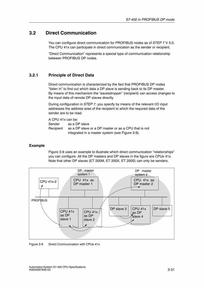
S7-400 in PROFIBUS DP mode
3-31Automation System S7-400 CPU SpecificationsA5E00267840-03
3.2 Direct Communication
You can configure direct communication for PROFIBUS nodes as of STEP 7 V 5.0.The CPU 41x can participate in direct communication as the sender or recipient.
“Direct Communication” represents a special type of communication relationshipbetween PROFIBUS DP nodes.
3.2.1 Principle of Direct Data
Direct communication is characterized by the fact that PROFIBUS DP nodes“listen in” to find out which data a DP slave is sending back to its DP master.By means of this mechanism the “eavesdropper” (recipient) can access changes tothe input data of remote DP slaves directly.
During configuration in STEP 7, you specify by means of the relevant I/O inputaddresses the address area of the recipient to which the required data of thesender are to be read.
A CPU 41x can be:Sender as a DP slaveRecipient as a DP slave or a DP master or as a CPU that is not
integrated in a master system (see Figure 3-9).
Example
Figure 3-9 uses an example to illustrate which direct communication “relationships”you can configure. All the DP masters and DP slaves in the figure are CPUs 41x.Note that other DP slaves (ET 200M, ET 200X, ET 200S) can only be senders.
PROFIBUS
CPU 41x as DP master 1
CPU 41x-2
DP slave 3 DP slave 5CPU 41x as DPslave 1
DP mastersystem 1
DP mastersystem 2
CPU 41x as DP master 2
CPU 41x as DPslave 2
CPU 41x as DPslave 4
Figure 3-9 Direct Communication with CPUs 41x
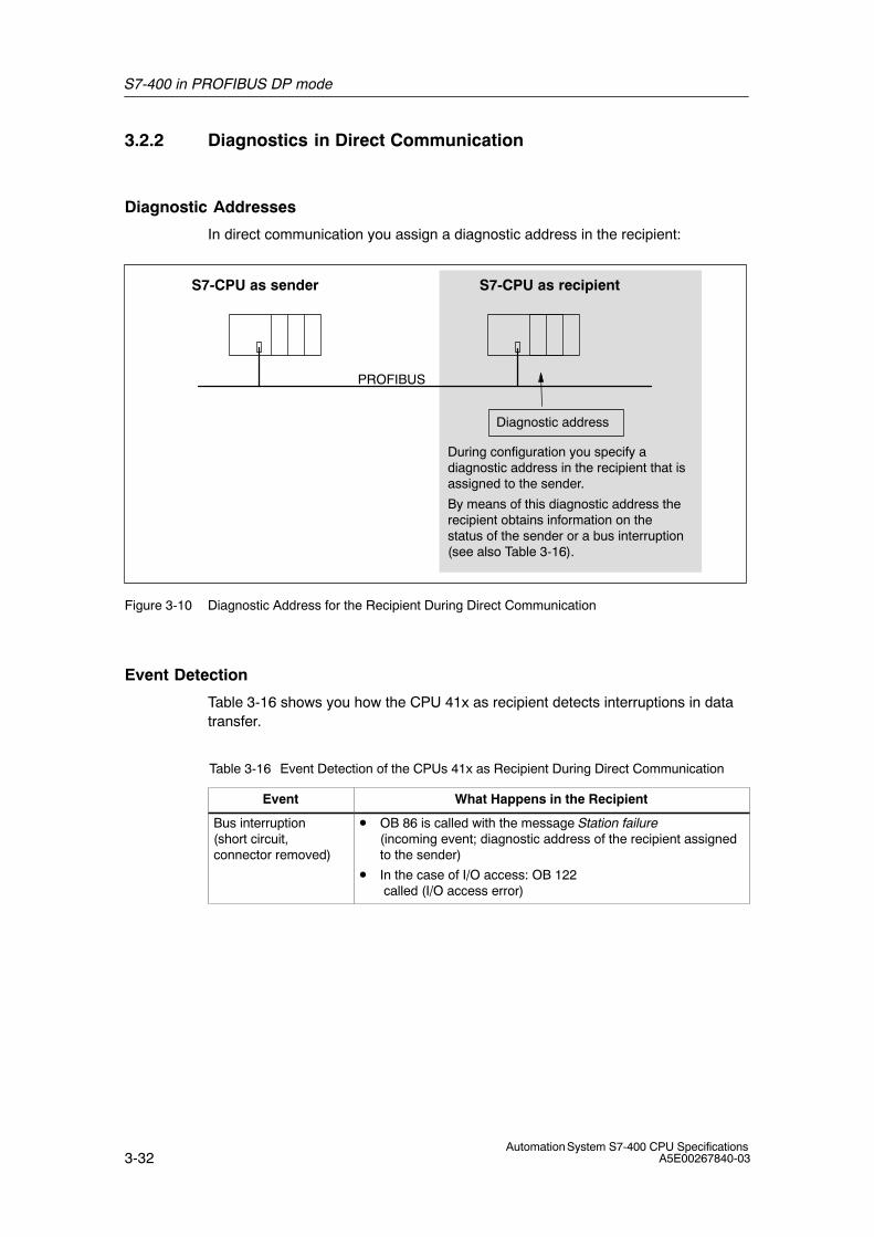
S7-400 in PROFIBUS DP mode
3-32Automation System S7-400 CPU Specifications
A5E00267840-03
3.2.2 Diagnostics in Direct Communication
Diagnostic Addresses
In direct communication you assign a diagnostic address in the recipient:
PROFIBUS
S7-CPU as recipientS7-CPU as sender
Diagnostic address
During configuration you specify adiagnostic address in the recipient that isassigned to the sender.
By means of this diagnostic address therecipient obtains information on thestatus of the sender or a bus interruption(see also Table 3-16).
Figure 3-10 Diagnostic Address for the Recipient During Direct Communication
Event Detection
Table 3-16 shows you how the CPU 41x as recipient detects interruptions in datatransfer.
Table 3-16 Event Detection of the CPUs 41x as Recipient During Direct Communication
Event What Happens in the Recipient
Bus interruption(short circuit,connector removed)
• OB 86 is called with the message Station failure(incoming event; diagnostic address of the recipient assignedto the sender)
• In the case of I/O access: OB 122 called (I/O access error)
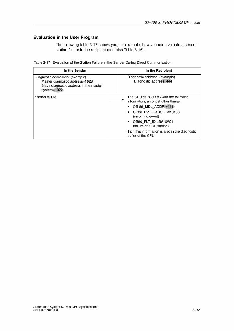
S7-400 in PROFIBUS DP mode
3-33Automation System S7-400 CPU SpecificationsA5E00267840-03
Evaluation in the User Program
The following table 3-17 shows you, for example, how you can evaluate a senderstation failure in the recipient (see also Table 3-16).
Table 3-17 Evaluation of the Station Failure in the Sender During Direct Communication
In the Sender In the Recipient
Diagnostic addresses: (example)Master diagnostic address=1023Slave diagnostic address in the mastersystem=1022
Diagnostic address: (example)Diagnostic address=444
Station failure The CPU calls OB 86 with the followinginformation, amongst other things:
• OB 86_MDL_ADDR:=444
• OB86_EV_CLASS:=B#16#38(incoming event)
• OB86_FLT_ID:=B#16#C4 (failure of a DP station)
Tip: This information is also in the diagnosticbuffer of the CPU
S7-400 in PROFIBUS DP mode
3-34Automation System S7-400 CPU Specifications
A5E00267840-03
3.3 Consistent Data
Data that belongs together in terms of its content and a process state written at aspecific point in time is known as consistent data. To maintain consistency, thedata should not be changed or updated during processing or transmission.
Example
To ensure that the CPU has a consistent image of the process signals for theduration of cyclic program scanning, the process signals are read from the processimage inputs prior to program scanning and written to the process image outputsafter the program scanning. Subsequently, during program scanning when theaddress area “inputs” (I) and “outputs” (O) are addressed, the user programaddresses the internal memory area of the CPU on which the image of the inputsand outputs is located instead of directly accessing the signal modules.
SFC 81 “UBLKMOV”
With SFC 81 “UBLKMOV” (uninterruptible block move), you can copy the contentsof a memory area (= source area) consistently to a different memory area(= destination area). The copy operation cannot be interrupted by other operatingsystem activities.
SFC 81 “UBLKMOV” enables you to copy the following memory areas:
• Memory markers
• DB contents
• Process image of the inputs
• Process image of outputs
The maximum amount of data you can copy is 512 bytes. Take into considerationthe restrictions for the specific CPU, which are documented in the operations list,for example.
Since copying cannot be interrupted, the interrupt reaction times of your CPU mayincrease when using SFC 81 “UBLKMOV”.
The source and destination areas must not overlap. If the specified destinationarea is larger than the source area, the function only copies as much data to thedestination area as that contained in the source area. If the specified destinationarea is smaller than the source area, the function only copies as much data as canbe written to the destination area.
For information on SFC 81, refer to the corresponding Online Help and to the“System and Standard Functions” manual.
S7-400 in PROFIBUS DP mode
3-35Automation System S7-400 CPU SpecificationsA5E00267840-03
3.3.1 Consistency for Communication Blocks and Functions
Using S7-400 the communication data is not processed in the scan cyclecheckpoint; instead, this data is processed in fixed time slices during the programcycle.
In the system the byte, word and double word data formats can always beprocessed consistently, in other words, the transfer or processing of 1 byte, 1 word(= 2 bytes) or 1 double word (= 4 bytes) cannot be interrupted.
If communication blocks (such as SFB 12 “BSEND”) are called in the userprogram, which are only used in pairs (such as SFB 12 “BSEND” und SFB 13“BRCV”) and which share access to data, the access to this data area can becoordinated between themselves, using the “DONE” parameter, for example. Dataconsistency of the communication areas transmitted locally with a communicationblock can thus be ensured in the user program.
S7 communication functions such as SFB 14 “GET”, SFB 15 “PUT” reactdifferently because no block is needed in the user program of the destinationdevice. In this case the size of data consistency has to be taken into accountbeforehand during the programming phase.
3.3.2 Access to the Working Memory of the CPU
The communication functions of the operating system access the working memoryof the CPU in fixed block lengths. The block size is a variable length up to amaximum of 462 bytes.
3.3.3 Reading from and Writing to a DP Standard Slave Consistently
Writing Data Consistently to a DP Standard Slave Using SFC 14 “DPRD_DAT”
Using SFC 14 “DPRD_DAT” (read consistent data of a DP standard slave) you canconsistently read the data of a DP standard slave.
The data read is entered into the destination range defined by RECORD if no erroroccurs during the data transmission.
The destination range must have the same length as the one you have configuredfor the selected module with STEP 7.
By invoking SFC 14 you can only access the data of one module / DP ID at theconfigured start address.
For information on SFC 14, refer to the corresponding Online Help and to the“System and Standard Functions” manual
S7-400 in PROFIBUS DP mode
3-36Automation System S7-400 CPU Specifications
A5E00267840-03
3.3.4 Writing Data Consistently to a DP Standard Slave Using SFC 15“DPWR_DAT”
Using SFC 15 “DPWR_DAT” (write consistent data to a DP standard slave) youcan consistently write data to the DP standard slave addressed in the RECORD.
The source range must have the same length as the one you have configured forthe selected module with STEP 7.
Note
The Profibus DP standard defines the upper limit for the transmission of consistentuser data (see following section). Typical DP standard slaves adhere to this upperlimit. In older CPUs (<1999) there are restrictions in the transmission of consistentuser data depending on the CPU. For these CPUs you can determine themaximum length of the data which the CPU can consistently read and write to andfrom the DP standard in the respective technical specifications under the indexentry “DP Master – User data per DP slave”. Newer CPUs are capable ofexceeding the value for the amount of data that a DP standard slave can send andreceive.
Upper Limit for the Transmission of Consistent User Data to a DP Slave
The Profibus DP standard defines the upper limit for the transmission of consistentuser data to a DP slave. For this reason a maximum of 64 words = 128 bytes ofuser data can be consistently transferred in a block to the DP slave.
During the configuration you can determine the size of the consistent area. Youcan set a maximum length of consistent data at 64 words = 128 bytes in thespecial identification format (SKF) (128 bytes for inputs and 128 bytes for outputs);the data block size cannot exceed this.
This upper limit only applies to pure user data. Diagnostics and parameter data areregrouped into full records and therefore always transferred consistently.
In the general identification format (AKF) the maximum length of consistent datacan be set at 16 words = 32 bytes (32 bytes for inputs and 32 bytes for outputs);the data block size cannot exceed this.
Note in this context that a CPU 41x in a general environment acting as a DP slaveon a third-party master (connection defined by GSD) has to be configured with thegeneral identification format. The transfer memory of a CPU 41x acting as a DPslave to the PROFIBUS DP can therefore be a maximum of 16 words = 32 bytes.
For information on SFC 15, refer to the corresponding Online Help and to the“System and Standard Functions” manual
S7-400 in PROFIBUS DP mode
3-37Automation System S7-400 CPU SpecificationsA5E00267840-03
3.3.5 Consistent Data Access without the Use of SFC 14 or SFC 15
Consistent data access of > 4 bytes without using SFC 14 or SFC 15 is possiblefor the CPUs describedin this manual. The data area of a DP slave that shouldtransfer consistently is transferred to a process image partition. The information inthis area is therefore always consistent. You can subsequently use load/transfercommands (such as L EW 1) to access the process image. This is an especiallyconvenient and efficient (low runtime load) way to access consistent data. Thisallows efficient integration and configuration of drives or other DP slaves, forexample.
An I/O access error does not occur with direct access (e.g. L PEW or T PAW).
The following is important for converting from the SFC14/15 method to the processimage method:
• When converting from the SFC14/15 method to the process image method, it isnot recommended to use the system functions and the process image at thesame time. Although the process image is updated when writing with thesystem function SFC15, this is not the case when reading. In other words, theconsistency between the process image values and the values of the systemfunction SFC14 is not ensured.
• SFC 50 “RD_LGADR” outputs another address area with the SFC 14/15method as with the process image method.
• If you are using a CP 443-5 ext the simultaneous use of SFC 14/15 and theprocess image results in the following errors, you cannot read/write into theprocess image and/or you can no longer read/write with SFC 14/15.
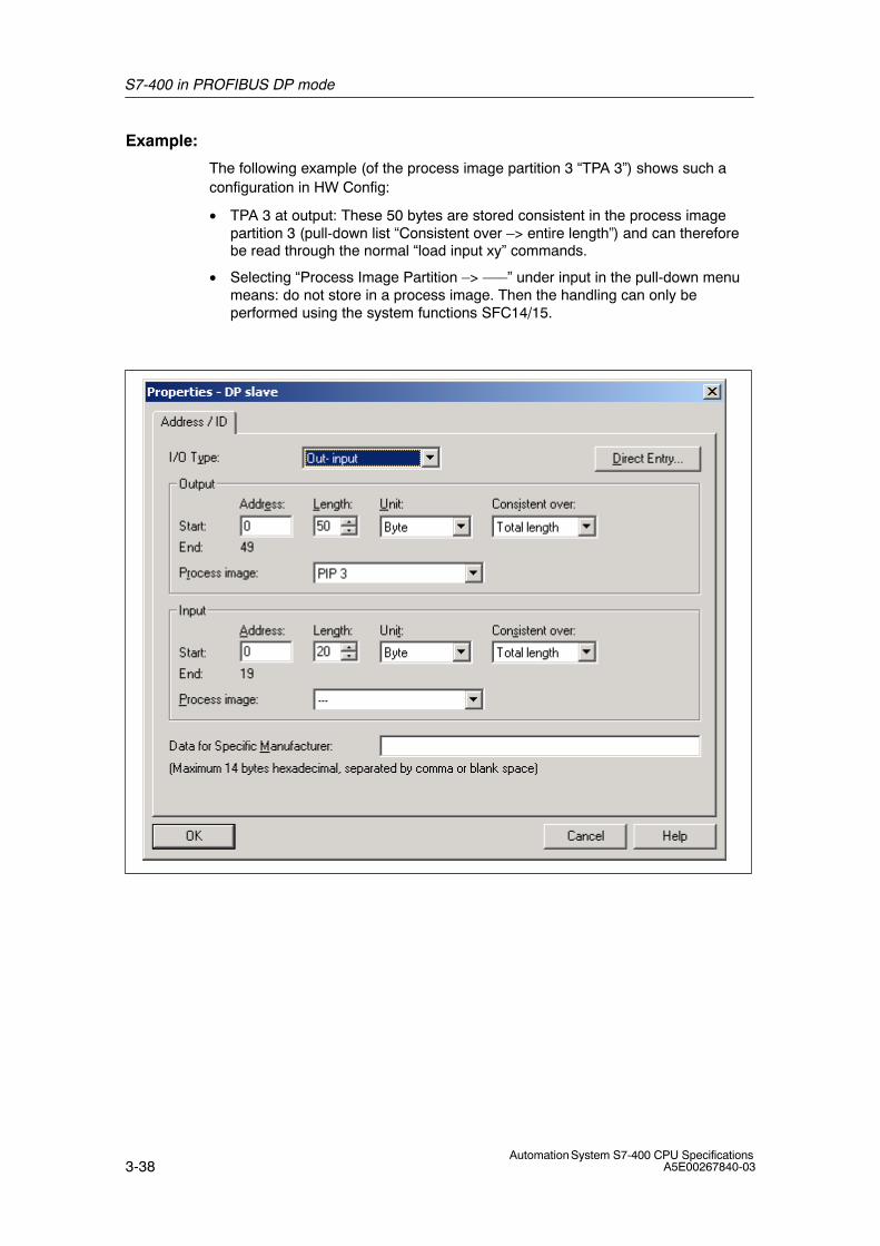
S7-400 in PROFIBUS DP mode
3-38Automation System S7-400 CPU Specifications
A5E00267840-03
Example:
The following example (of the process image partition 3 “TPA 3”) shows such aconfiguration in HW Config:
• TPA 3 at output: These 50 bytes are stored consistent in the process imagepartition 3 (pull-down list “Consistent over –> entire length”) and can thereforebe read through the normal “load input xy” commands.
• Selecting “Process Image Partition –> –––” under input in the pull-down menumeans: do not store in a process image. Then the handling can only beperformed using the system functions SFC14/15.
4-1Automation System S7-400 CPU SpecificationsA5E00267840-03
Memory Concept and Startup Scenarios
Chapter Overview
In Section You will find On Page
4.1 Overview of the Memory Concept of S7-400 CPUs 4-2
4.2 Overview of the Startup Scenarios for S7-400-CPUs 4-5
4
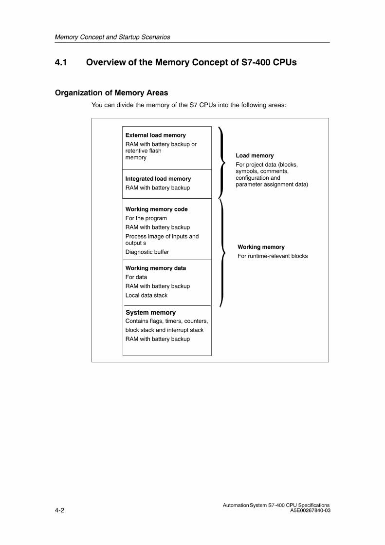
Memory Concept and Startup Scenarios
4-2Automation System S7-400 CPU Specifications
A5E00267840-03
4.1 Overview of the Memory Concept of S7-400 CPUs
Organization of Memory Areas
You can divide the memory of the S7 CPUs into the following areas:
Integrated load memory
RAM with battery backup
External load memory
RAM with battery backup or retentive flash memory
Working memory code
For the program
RAM with battery backup
Process image of inputs andoutput s
Diagnostic buffer
Working memory data
For data
RAM with battery backup
Local data stack
Load memory
For project data (blocks,symbols, comments,configuration and parameter assignment data)
Working memory
For runtime-relevant blocks
System memoryContains flags, timers, counters,
block stack and interrupt stack
RAM with battery backup
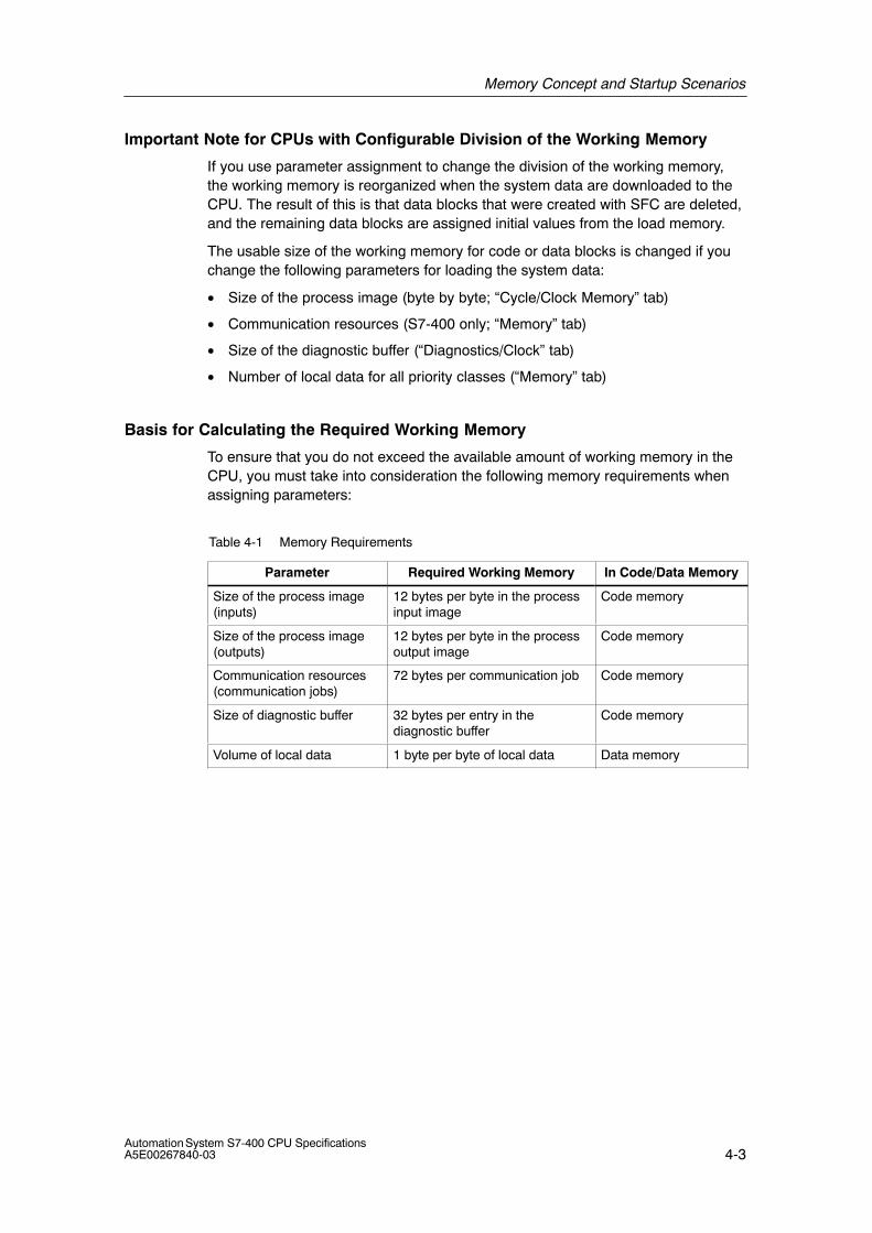
Memory Concept and Startup Scenarios
4-3Automation System S7-400 CPU SpecificationsA5E00267840-03
Important Note for CPUs with Configurable Division of the Working Memory
If you use parameter assignment to change the division of the working memory,the working memory is reorganized when the system data are downloaded to theCPU. The result of this is that data blocks that were created with SFC are deleted,and the remaining data blocks are assigned initial values from the load memory.
The usable size of the working memory for code or data blocks is changed if youchange the following parameters for loading the system data:
• Size of the process image (byte by byte; “Cycle/Clock Memory” tab)
• Communication resources (S7-400 only; “Memory” tab)
• Size of the diagnostic buffer (“Diagnostics/Clock” tab)
• Number of local data for all priority classes (“Memory” tab)
Basis for Calculating the Required Working Memory
To ensure that you do not exceed the available amount of working memory in theCPU, you must take into consideration the following memory requirements whenassigning parameters:
Table 4-1 Memory Requirements
Parameter Required Working Memory In Code/Data Memory
Size of the process image(inputs)
12 bytes per byte in the processinput image
Code memory
Size of the process image(outputs)
12 bytes per byte in the processoutput image
Code memory
Communication resources(communication jobs)
72 bytes per communication job Code memory
Size of diagnostic buffer 32 bytes per entry in thediagnostic buffer
Code memory
Volume of local data 1 byte per byte of local data Data memory
Memory Concept and Startup Scenarios
4-4Automation System S7-400 CPU Specifications
A5E00267840-03
Memory Types in S7-400 CPUs
• Load memory for project data, such as blocks, configuration and parameterassignment data, including symbols and comments as of version 5.1.
• Working memory for the runtime-relevant blocks (code blocks and data blocks).
• System memory (RAM) contains the memory elements that each CPU makesavailable to the user program, such as memory markers, timers, and counters.The system memory also receives the block stack and the interrupt stack.
• System memory of the CPU also makes temporary memory available (localdata stack, diagnostic buffer and communication resources) that is assigned tothe program when a block is called for its temporary data. These data are onlyvalid as long as the block is active.
By changing the default values for the process image, local data, diagnosticbuffer and communication resources (see the object properties of the CPU inHWConfig), you can control the working memory available to theruntime-relevant blocks.
Notice
Please note the following if you enlarge the process image of a CPU. Make surethat you configure the modules that can only be operated above the processimage in such a way that they are also positioned above the enlarged processimage. This particularly applies to IP and WF modules that you operate in the S5adapter casing in a S7-400.
Flexible Memory Capacity
• Working memory:
The capacity of the working memory is determined by selecting the appropriateCPU from the graded range of CPUs.
• Load memory:
The integrated load memory is sufficient for small and medium-sized programs.
The load memory can be increased for larger programs by inserting the RAMmemory card.
Flash memory cards are also available to ensure that programs are retained inthe event of a power failure even if there isn’t a backup battery. Flash memorycards can also be used (as of 4 MB) to send and execute operating systemupdates.
Backup
• The backup battery provides backup power for the integrated and external partof the load memory, the data section of the working memory and the codesection.
Memory Concept and Startup Scenarios
4-5Automation System S7-400 CPU SpecificationsA5E00267840-03
4.2 Overview of the Startup Scenarios for S7-400 CPUs
Cold Restart
• At the restart, all data (process image, memory markers, timers, counters anddata blocks) are reset to the start values stored in the program (load memory),irrespective of whether they were configured as retentive or non-retentive.
Retentive flags, timers and counters retain their last valid value.
All All DBs assigned the “Non Retain” attribute are reset to the load values. Theremaining blocks retain their last valid value.
• Program processing is started from the beginning again (startup OB or OB 1).
Warm Restart
• At a warm restart, the process image and the non-retentive memory markers,timers and counters are reset.
Retentive flags, timers and counters retain their last valid value.
• Program execution is started from the beginning again (startup OB or OB 1).
• When the power supply is interrupted, a warm restart is only possible in backupmode.
Hot Restart
• At a hot restart, all the data, including the process image, retain their last validvalue.
• Program processing is resumed at the breakpoint.
• The outputs are not changed until the end of the current cycle.
• When the power supply is interrupted, a restart is only possible in backed-upmode.

Memory Concept and Startup Scenarios
4-6Automation System S7-400 CPU Specifications
A5E00267840-03
5-1Automation System S7-400 CPU SpecificationsA5E00267840-03
Cycle and Reaction Times of the S7-400
This chapter explains the composition of the cycle and reaction times of theS7-400.
You can display the cycle time of your user program on the relevant CPU using theprogramming device (see manual Configuring Hardware and CommunicationConnections with STEP 7 Version 5.0 or higher).
Examples will illustrate how you calculate the cycle time.
The reaction time is important for monitoring a process. This chapter provides adetailed description of how to calculate this. If you use a CPU 41x-2 DP as amaster in the PROFIBUS DP network, you also have to take into account DPcycle times (see Section 5.5).
Chapter Overview
Section Description Page
5.1 Cycle Time 5-2
5.2 Cycle Time Calculation 5-4
5.3 Different Cycle Times 5-7
5.4 Communication Load 5-9
5.5 Reaction Time 5-12
5.6 How Cycle and Reaction Times Are Calculated 5-17
5.6 Examples of Calculating the Cycle Time and Reaction Time 5-17
5.8 Interrupt Reaction Time 5-21
5.9 Example of Calculating the Interrupt Reaction Time 5-23
5.10 Reproducibility of Time-Delay and Watchdog Interrupts 5-24
Further Information
You will find further information on the following processing times in the S7-400Instruction List. It lists all the STEP 7 instructions that can be processed by therelevant CPUs, together with their execution times and all the SFCs/SFBsintegrated in the CPUs and the IEC functions that can be called in STEP 7,together with their processing times.
5
Cycle and Reaction Times of the S7-400
5-2Automation System S7-400 CPU Specifications
A5E00267840-03
5.1 Cycle Time
In this chapter you will learn about the composition of the cycle time and how youcan calculate the cycle time.
Definition of the Cycle Time
The cycle time is the time which the operating system needs to process a programrun – in other words, an OB 1 run – and all the program segments and systemactivities that interrupt that run.
This time is monitored.
Time-Sharing Model
Cyclic program scanning, and thus also processing of the user program, isperformed in time slices. So that you can better appreciate these processes, wewill assume in the following that each time slice is exactly 1 ms long.
Process Image
The process signals are read or written prior to program scanning so that aconsistent image of the process signals is available to the CPU for the duration ofcyclic program scanning. Then the CPU does not directly access the signalmodules during program scanning when the address area “inputs” (I) and “outputs”(O) are addressed, but addresses instead the internal memory area of the CPU onwhich the image of the inputs and outputs is located.
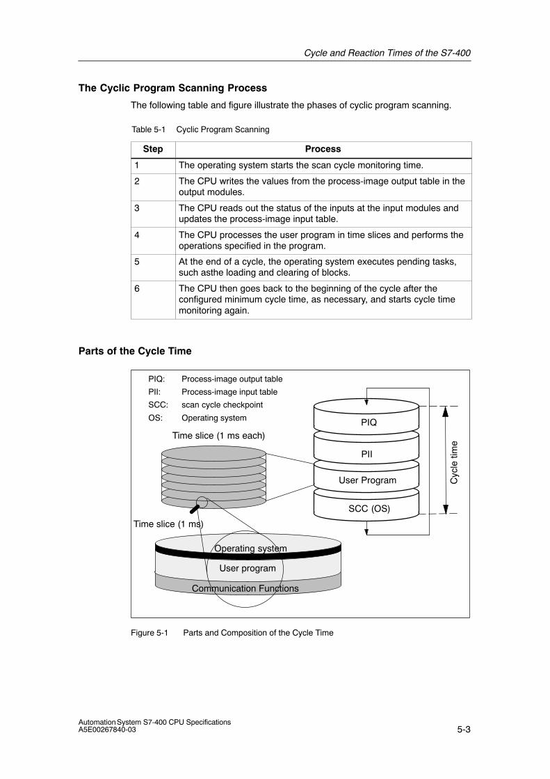
Cycle and Reaction Times of the S7-400
5-3Automation System S7-400 CPU SpecificationsA5E00267840-03
The Cyclic Program Scanning Process
The following table and figure illustrate the phases of cyclic program scanning.
Table 5-1 Cyclic Program Scanning
Step Process
1 The operating system starts the scan cycle monitoring time.
2 The CPU writes the values from the process-image output table in theoutput modules.
3 The CPU reads out the status of the inputs at the input modules andupdates the process-image input table.
4 The CPU processes the user program in time slices and performs theoperations specified in the program.
5 At the end of a cycle, the operating system executes pending tasks,such asthe loading and clearing of blocks.
6 The CPU then goes back to the beginning of the cycle after theconfigured minimum cycle time, as necessary, and starts cycle timemonitoring again.
Parts of the Cycle Time
SCC (OS)
User Program
PII
PIQ
PIQ: Process-image output table
PII: Process-image input table
SCC: scan cycle checkpoint
OS: Operating system
Time slice (1 ms each)
Time slice (1 ms)
User program
Communication Functions
Operating system
Cyc
le ti
me
Figure 5-1 Parts and Composition of the Cycle Time

Cycle and Reaction Times of the S7-400
5-4Automation System S7-400 CPU Specifications
A5E00267840-03
5.2 Cycle Time Calculation
Increasing the Cycle Time
Basically, you should note that the cycle time of a user program is increased by thefollowing:
• Time-driven interrupt processing
• Hardware interrupt processing (see also Section 5.8)
• Diagnostics and error handling (see also Section 5.9)
• Communications via the MPI and CPs connected via the communication bus(for example, Ethernet, Profibus, DP); contained in the communication load
• Special functions such as control and monitoring of variables or block status
• Transfer and clearance of blocks, compression of the user program memory
Factors that Influence the Cycle Time
The following table indicates the factors that influence the cycle time.
Table 5-2 Factors that Influence the Cycle Time
Factors Remark
Transfer time for theprocess-image output table(PIQ) and the process-imageinput table (PII)
... see Table 5-3
User program processingtime
... is calculated from the execution times of the differentinstructions (see S7-400 Instruction List).
Operating system scan timeat scan cycle checkpoint
... see Table 5-4
Increase in the cycle timefrom communications
You set the maximum permissible cycle load expected forcommunication in % in STEP 7 (manual Programming withSTEP 7). See Section 5.4.
Impact of interrupts on thecycle time
Interrupt can interrupt the user program at any time.
... see Table 5-5
NoteWith CPUs produced prior to October 1998, updating of the process image of theoutputs takes place before the scan cycle checkpoint.
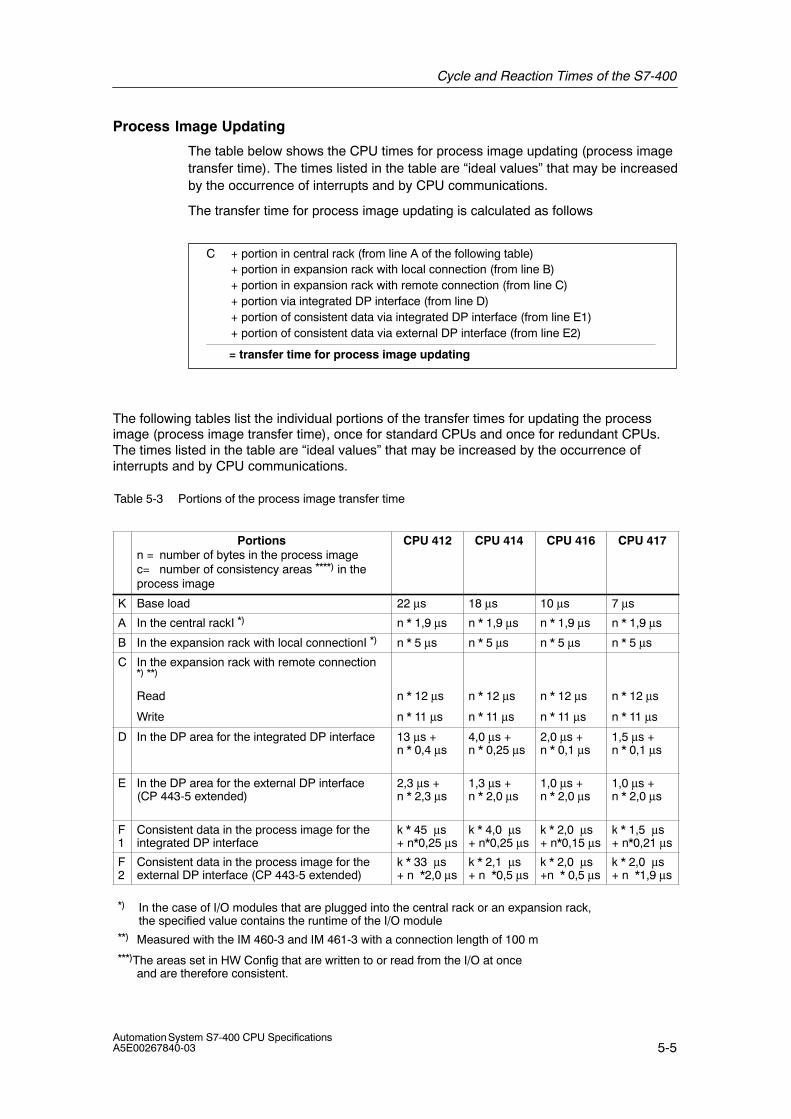
Cycle and Reaction Times of the S7-400
5-5Automation System S7-400 CPU SpecificationsA5E00267840-03
Process Image Updating
The table below shows the CPU times for process image updating (process imagetransfer time). The times listed in the table are “ideal values” that may be increasedby the occurrence of interrupts and by CPU communications.
The transfer time for process image updating is calculated as follows
C + portion in central rack (from line A of the following table)+ portion in expansion rack with local connection (from line B)+ portion in expansion rack with remote connection (from line C)+ portion via integrated DP interface (from line D)+ portion of consistent data via integrated DP interface (from line E1)+ portion of consistent data via external DP interface (from line E2)
= transfer time for process image updating
The following tables list the individual portions of the transfer times for updating the processimage (process image transfer time), once for standard CPUs and once for redundant CPUs.The times listed in the table are “ideal values” that may be increased by the occurrence ofinterrupts and by CPU communications.
Table 5-3 Portions of the process image transfer time
Portionsn = number of bytes in the process imagec= number of consistency areas ****) in theprocess image
CPU 412 CPU 414 CPU 416 CPU 417
K Base load 22 μs 18 μs 10 μs 7 μs
A In the central rackI *) n * 1,9 μs n * 1,9 μs n * 1,9 μs n * 1,9 μs
B In the expansion rack with local connectionI *) n * 5 μs n * 5 μs n * 5 μs n * 5 μs
C In the expansion rack with remote connection*) **)
Read
Write
n * 12 μs
n * 11 μs
n * 12 μs
n * 11 μs
n * 12 μs
n * 11 μs
n * 12 μs
n * 11 μs
D In the DP area for the integrated DP interface 13 μs + n * 0,4 μs
4,0 μs + n * 0,25 μs
2,0 μs + n * 0,1 μs
1,5 μs + n * 0,1 μs
E In the DP area for the external DP interface(CP 443-5 extended)
2,3 μs + n * 2,3 μs
1,3 μs + n * 2,0 μs
1,0 μs + n * 2,0 μs
1,0 μs + n * 2,0 μs
F1
Consistent data in the process image for theintegrated DP interface
k * 45 μs+ n*0,25 μs
k * 4,0 μs+ n*0,25 μs
k * 2,0 μs+ n*0,15 μs
k * 1,5 μs+ n*0,21 μs
F2
Consistent data in the process image for theexternal DP interface (CP 443-5 extended)
k * 33 μs+ n *2,0 μs
k * 2,1 μs+ n *0,5 μs
k * 2,0 μs+n * 0,5 μs
k * 2,0 μs+ n *1,9 μs
*) In the case of I/O modules that are plugged into the central rack or an expansion rack,the specified value contains the runtime of the I/O module
**) Measured with the IM 460-3 and IM 461-3 with a connection length of 100 m***)The areas set in HW Config that are written to or read from the I/O at once
and are therefore consistent.
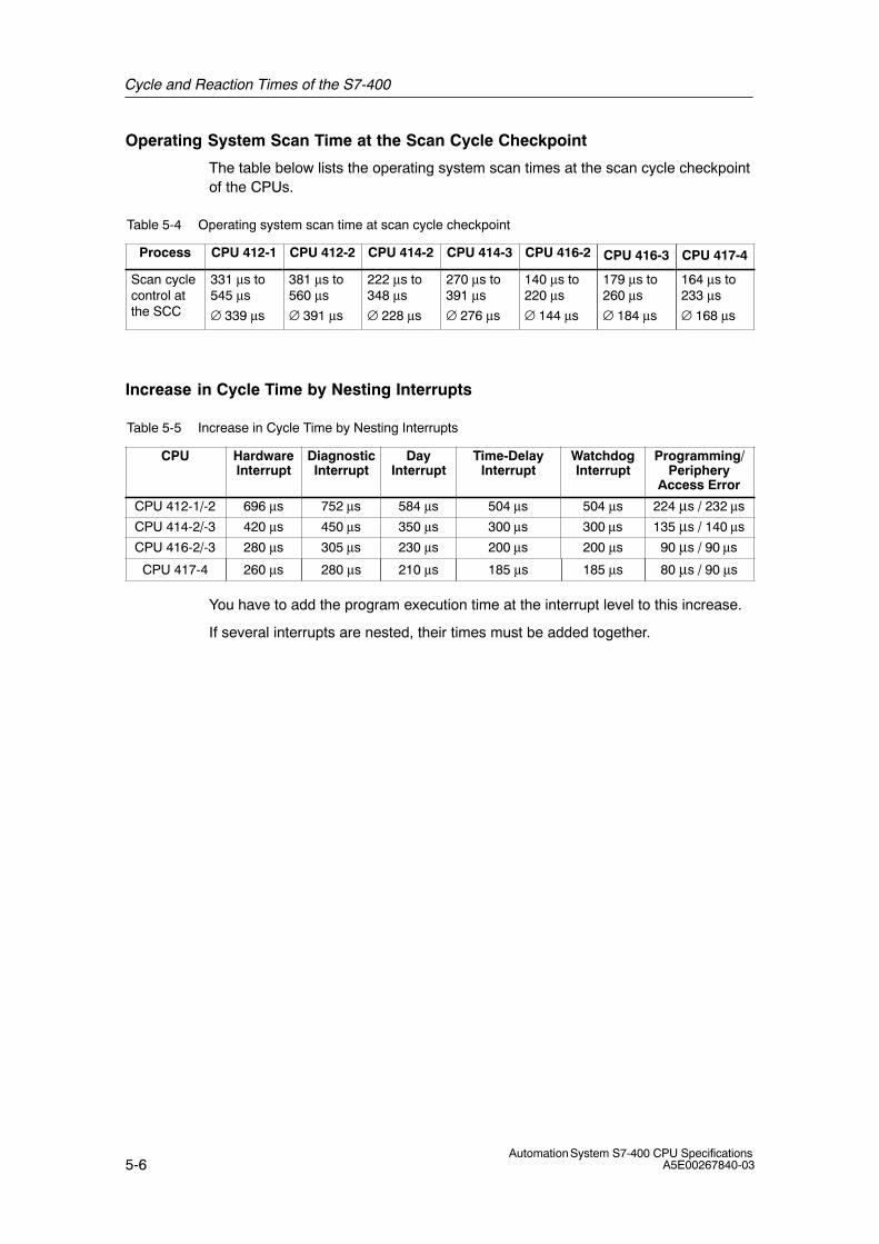
Cycle and Reaction Times of the S7-400
5-6Automation System S7-400 CPU Specifications
A5E00267840-03
Operating System Scan Time at the Scan Cycle Checkpoint
The table below lists the operating system scan times at the scan cycle checkpointof the CPUs.
Table 5-4 Operating system scan time at scan cycle checkpoint
Process CPU 412-1 CPU 412-2 CPU 414-2 CPU 414-3 CPU 416-2 CPU 416-3 CPU 417-4
Scan cyclecontrol atthe SCC
331 μs to545 μs
∅ 339 μs
381 μs to560 μs
∅ 391 μs
222 μs to348 μs
∅ 228 μs
270 μs to391 μs
∅ 276 μs
140 μs to220 μs
∅ 144 μs
179 μs to260 μs
∅ 184 μs
164 μs to233 μs
∅ 168 μs
Increase in Cycle Time by Nesting Interrupts
Table 5-5 Increase in Cycle Time by Nesting Interrupts
CPU HardwareInterrupt
DiagnosticInterrupt
DayInterrupt
Time-DelayInterrupt
WatchdogInterrupt
Programming/Periphery
Access Error
CPU 412-1/-2 696 μs 752 μs 584 μs 504 μs 504 μs 224 μs / 232 μs
CPU 414-2/-3 420 μs 450 μs 350 μs 300 μs 300 μs 135 μs / 140 μs
CPU 416-2/-3 280 μs 305 μs 230 μs 200 μs 200 μs 90 μs / 90 μs
CPU 417-4 260 μs 280 μs 210 μs 185 μs 185 μs 80 μs / 90 μs
You have to add the program execution time at the interrupt level to this increase.
If several interrupts are nested, their times must be added together.
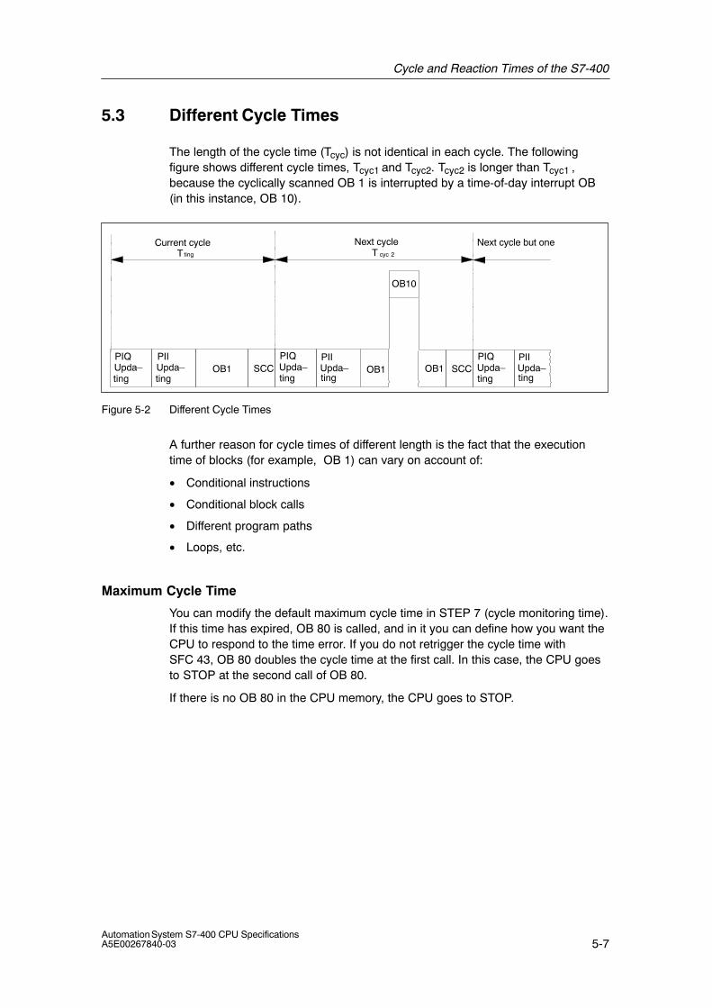
Cycle and Reaction Times of the S7-400
5-7Automation System S7-400 CPU SpecificationsA5E00267840-03
5.3 Different Cycle Times
The length of the cycle time (Tcyc) is not identical in each cycle. The followingfigure shows different cycle times, Tcyc1 and Tcyc2. Tcyc2 is longer than Tcyc1 ,because the cyclically scanned OB 1 is interrupted by a time-of-day interrupt OB(in this instance, OB 10).
Current cycle Next cycle
OB10
T
OB1PIQUpda–
ting
ting
PIIUpda–ting
SCC OB1PIQUpda–ting
PIIUpda–ting
SCCOB1
cyc 2TNext cycle but one
PIQUpda–ting
PIIUpda–ting
Figure 5-2 Different Cycle Times
A further reason for cycle times of different length is the fact that the executiontime of blocks (for example, OB 1) can vary on account of:
• Conditional instructions
• Conditional block calls
• Different program paths
• Loops, etc.
Maximum Cycle Time
You can modify the default maximum cycle time in STEP 7 (cycle monitoring time).If this time has expired, OB 80 is called, and in it you can define how you want theCPU to respond to the time error. If you do not retrigger the cycle time withSFC 43, OB 80 doubles the cycle time at the first call. In this case, the CPU goesto STOP at the second call of OB 80.
If there is no OB 80 in the CPU memory, the CPU goes to STOP.
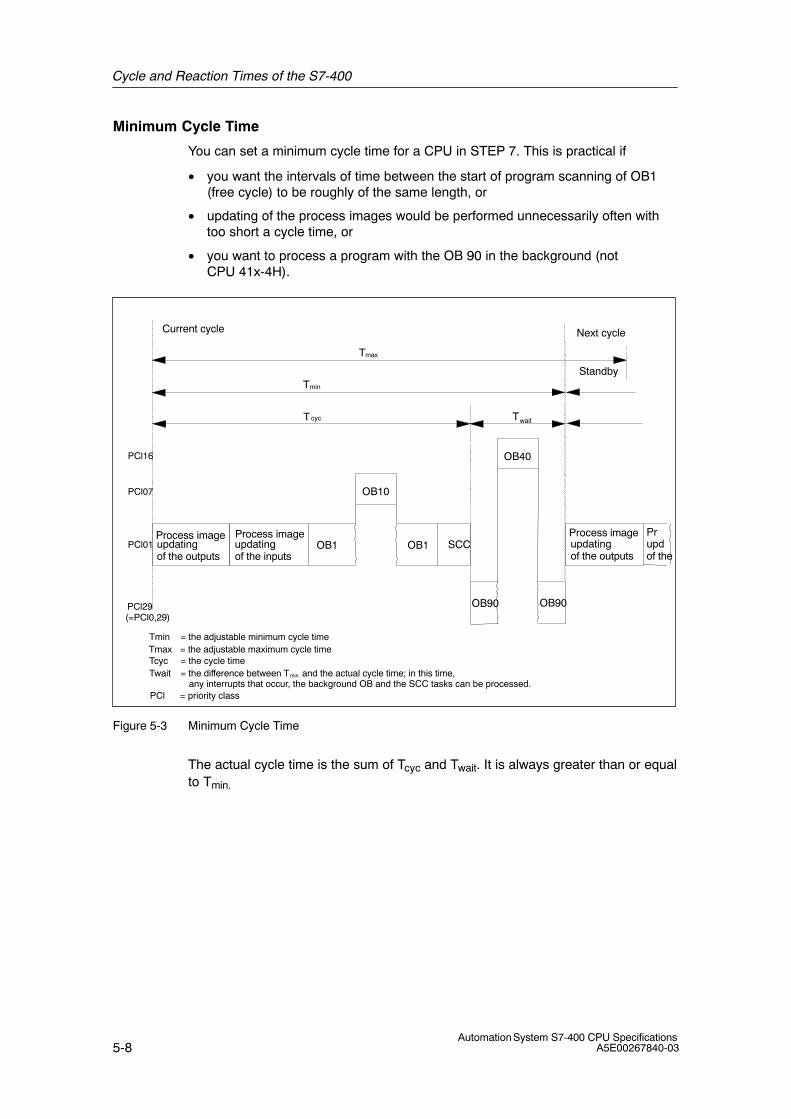
Cycle and Reaction Times of the S7-400
5-8Automation System S7-400 CPU Specifications
A5E00267840-03
Minimum Cycle Time
You can set a minimum cycle time for a CPU in STEP 7. This is practical if
• you want the intervals of time between the start of program scanning of OB1(free cycle) to be roughly of the same length, or
• updating of the process images would be performed unnecessarily often withtoo short a cycle time, or
• you want to process a program with the OB 90 in the background (notCPU 41x-4H).
Current cycle Next cycle
OB10
OB40
T
Tmin
Tmax
Twait
OB1updatingof the outputs
updatingof the inputs
updatingof the outputs
OB90 OB90
Tmin
TcycTwait
Prupdof the
= the adjustable minimum cycle time
= the cycle time= the difference between Tmin and the actual cycle time; in this time, any interrupts that occur, the background OB and the SCC tasks can be processed.
cyc
Standby
PCl = priority class
PCl16
PCl07
PCl01
PCl29(=PCl0,29)
Tmax = the adjustable maximum cycle time
SCCOB1Process imageProcess image Process image
Figure 5-3 Minimum Cycle Time
The actual cycle time is the sum of Tcyc and Twait. It is always greater than or equalto Tmin.
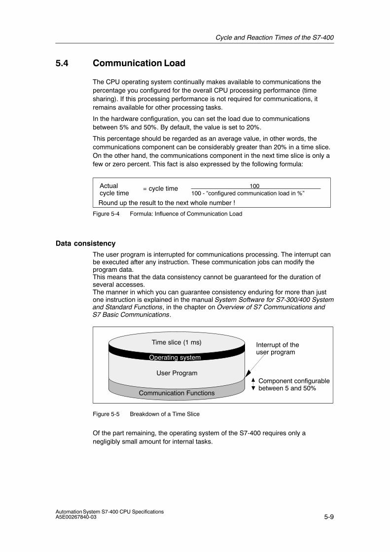
Cycle and Reaction Times of the S7-400
5-9Automation System S7-400 CPU SpecificationsA5E00267840-03
5.4 Communication Load
The CPU operating system continually makes available to communications thepercentage you configured for the overall CPU processing performance (timesharing). If this processing performance is not required for communications, itremains available for other processing tasks.
In the hardware configuration, you can set the load due to communicationsbetween 5% and 50%. By default, the value is set to 20%.
This percentage should be regarded as an average value, in other words, thecommunications component can be considerably greater than 20% in a time slice.On the other hand, the communications component in the next time slice is only afew or zero percent. This fact is also expressed by the following formula:
100100 - “configured communication load in %”
Actualcycle time
= cycle time
Round up the result to the next whole number !
Figure 5-4 Formula: Influence of Communication Load
Data consistency
The user program is interrupted for communications processing. The interrupt canbe executed after any instruction. These communication jobs can modify theprogram data.This means that the data consistency cannot be guaranteed for the duration ofseveral accesses.The manner in which you can guarantee consistency enduring for more than justone instruction is explained in the manual System Software for S7-300/400 Systemand Standard Functions, in the chapter on Overview of S7 Communications andS7 Basic Communications.
Time slice (1 ms)
User Program
Communication Functions
Operating system
Component configurablebetween 5 and 50%
Interrupt of theuser program
Figure 5-5 Breakdown of a Time Slice
Of the part remaining, the operating system of the S7-400 requires only anegligibly small amount for internal tasks.
Cycle and Reaction Times of the S7-400
5-10Automation System S7-400 CPU Specifications
A5E00267840-03
Example: 20 % Communication Load
You have configured a communication load of 20% in the hardware configuration.
The calculated cycle time is 10 ms.
A 20% communication load means that, on average, 200 μs and 800 μs of the timeslice remain for communications and the user program, respectively. The CPUtherefore requires 10 ms / 800 μs = 13 time slices to process one cycle. Thismeans that the actual cycle time is 13 times a 1 ms time slice = 13 ms, if the CPUfully utilizes the configured communication load.
This means that 20% communications do not increase the cycle linearly by 2 msbut by 3 ms.
Example: 50 % Communication Load
You have configured a communication load of 50% in the hardware configuration.
The calculated cycle time is 10 ms.
This means that 500 μs of each time slice remain for the cycle. The CPU thereforerequires 10 ms / 500 μs = 20 time slices to process one cycle. This means thatthe actual cycle time is 20 ms if the CPU fully utilizes the configuredcommunication load.
A 50 % communication load means that, on average, 500 μs and 500 μs of thetime slice remain for communications and the user program, respectively. The CPUtherefore requires 10 ms / 500 μs = 20 time slices to process one cycle. Thismeans that the actual cycle time is 20 times a 1 ms time slice = 20 ms, if the CPUfully utilizes the configured communication load.
This means that 50% communications do not increase the cycle linearly by 5 msbut by 10 ms.
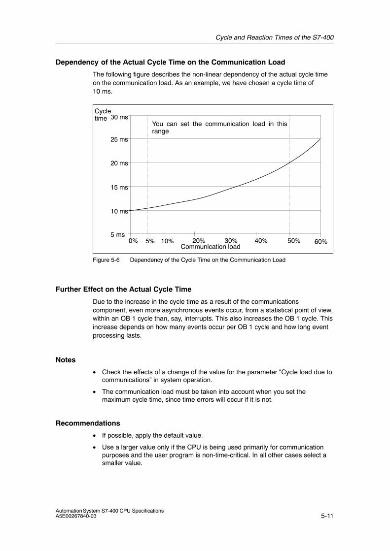
Cycle and Reaction Times of the S7-400
5-11Automation System S7-400 CPU SpecificationsA5E00267840-03
Dependency of the Actual Cycle Time on the Communication Load
The following figure describes the non-linear dependency of the actual cycle timeon the communication load. As an example, we have chosen a cycle time of10 ms.
You can set the communication load in thisrange
0% 10% 20% 30% 40% 50% 60%Communication load
Cycletime
10 ms
20 ms
25 ms
15 ms
5 ms
30 ms
5%
Figure 5-6 Dependency of the Cycle Time on the Communication Load
Further Effect on the Actual Cycle Time
Due to the increase in the cycle time as a result of the communicationscomponent, even more asynchronous events occur, from a statistical point of view,within an OB 1 cycle than, say, interrupts. This also increases the OB 1 cycle. Thisincrease depends on how many events occur per OB 1 cycle and how long eventprocessing lasts.
Notes
• Check the effects of a change of the value for the parameter “Cycle load due tocommunications” in system operation.
• The communication load must be taken into account when you set themaximum cycle time, since time errors will occur if it is not.
Recommendations
• If possible, apply the default value.
• Use a larger value only if the CPU is being used primarily for communicationpurposes and the user program is non-time-critical. In all other cases select asmaller value.
Cycle and Reaction Times of the S7-400
5-12Automation System S7-400 CPU Specifications
A5E00267840-03
5.5 Reaction Time
Definition of the Reaction Time
The reaction time is the time from an input signal being detected to changing anoutput signal linked to it.
Variation
The actual reaction time is somewhere between a shortest and a longest reactiontime. For configuring your system, you must always reckon with the longestreaction time.
The shortest and longest reaction times are analyzed below so that you can gainan impression of the variation of the reaction time.
Factors
The reaction time depends on the cycle time and on the following factors:
• Delay in the inputs and outputs
• Additional DP cycle times on the PROFIBUS-DP network
• Execution of the user program
Delay in the Inputs and Outputs
Depending on the module, you must heed the following time delays:
• For digital inputs: the input delay
• For interrupt-capable digital inputs: the input delay +the module-internal preparation time
• For digital outputs: negligible time delays
• For relay outputs: typical time delays from 10 to 20 ms.The delay of the relay outputs depends, among other things, on the temperature and voltage.
• For analog inputs: cycle time of analog input module
• For analog outputs: response time of the analog output module
The time delays can be found in the technical specifications of the signal modules.
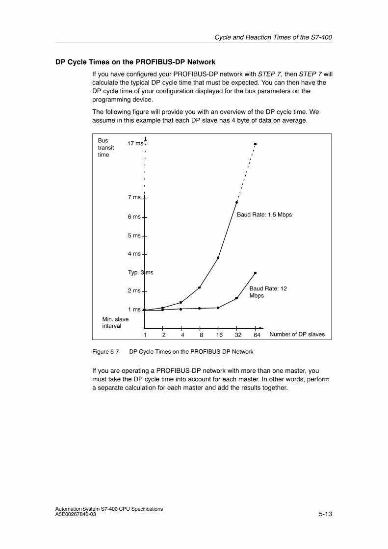
Cycle and Reaction Times of the S7-400
5-13Automation System S7-400 CPU SpecificationsA5E00267840-03
DP Cycle Times on the PROFIBUS-DP Network
If you have configured your PROFIBUS-DP network with STEP 7, then STEP 7 willcalculate the typical DP cycle time that must be expected. You can then have theDP cycle time of your configuration displayed for the bus parameters on theprogramming device.
The following figure will provide you with an overview of the DP cycle time. Weassume in this example that each DP slave has 4 byte of data on average.
Number of DP slaves
6 ms
4 ms
2 ms
1 2 4 8 16 32
Baud Rate: 12Mbps
Baud Rate: 1.5 Mbps
1 ms
Typ. 3 ms
5 ms
7 ms
Min. slaveinterval
64
Bustransittime
17 ms
Figure 5-7 DP Cycle Times on the PROFIBUS-DP Network
If you are operating a PROFIBUS-DP network with more than one master, youmust take the DP cycle time into account for each master. In other words, performa separate calculation for each master and add the results together.
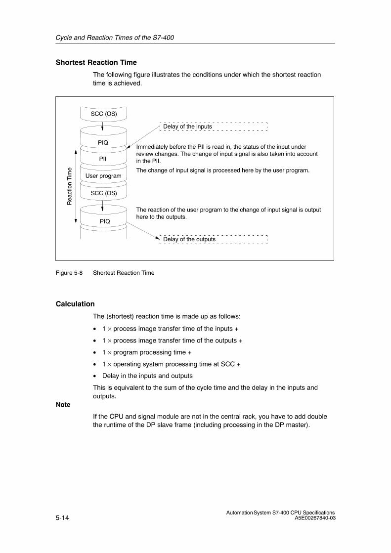
Cycle and Reaction Times of the S7-400
5-14Automation System S7-400 CPU Specifications
A5E00267840-03
Shortest Reaction Time
The following figure illustrates the conditions under which the shortest reactiontime is achieved.
Immediately before the PII is read in, the status of the input underreview changes. The change of input signal is also taken into accountin the PII.
The change of input signal is processed here by the user program.
The reaction of the user program to the change of input signal is outputhere to the outputs.
Rea
ctio
n T
ime
Delay of the inputs
Delay of the outputs
SCC (OS)
User program
PII
PIQ
PIQ
SCC (OS)
Figure 5-8 Shortest Reaction Time
Calculation
The (shortest) reaction time is made up as follows:
• 1 × process image transfer time of the inputs +
• 1 × process image transfer time of the outputs +
• 1 × program processing time +
• 1 × operating system processing time at SCC +
• Delay in the inputs and outputs
This is equivalent to the sum of the cycle time and the delay in the inputs andoutputs.
Note
If the CPU and signal module are not in the central rack, you have to add doublethe runtime of the DP slave frame (including processing in the DP master).
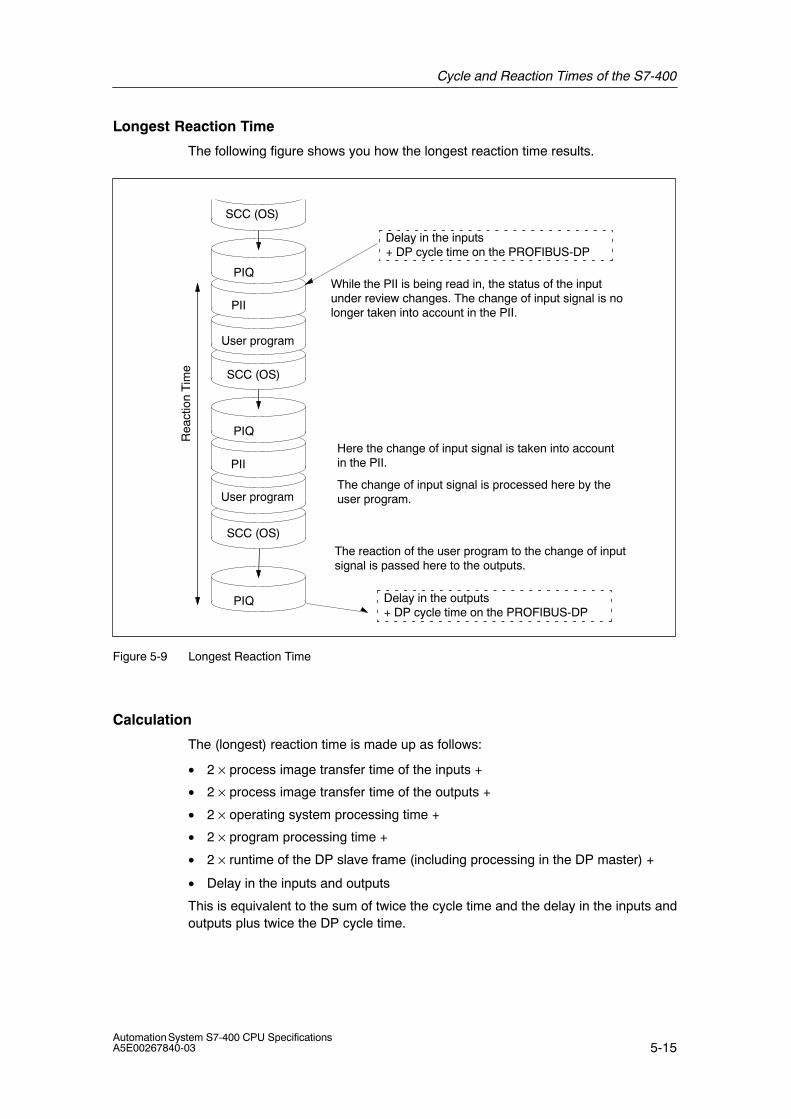
Cycle and Reaction Times of the S7-400
5-15Automation System S7-400 CPU SpecificationsA5E00267840-03
Longest Reaction Time
The following figure shows you how the longest reaction time results.
While the PII is being read in, the status of the inputunder review changes. The change of input signal is nolonger taken into account in the PII.
Here the change of input signal is taken into accountin the PII.
The change of input signal is processed here by theuser program.
The reaction of the user program to the change of inputsignal is passed here to the outputs.
Rea
ctio
n T
ime
Delay in the inputs+ DP cycle time on the PROFIBUS-DP
Delay in the outputs+ DP cycle time on the PROFIBUS-DP
SCC (OS)
User program
PII
PIQ
PIQ
SCC (OS)
SCC (OS)
User program
PII
PIQ
Figure 5-9 Longest Reaction Time
Calculation
The (longest) reaction time is made up as follows:
• 2 × process image transfer time of the inputs +
• 2 × process image transfer time of the outputs +
• 2 × operating system processing time +
• 2 × program processing time +
• 2 × runtime of the DP slave frame (including processing in the DP master) +
• Delay in the inputs and outputs
This is equivalent to the sum of twice the cycle time and the delay in the inputs andoutputs plus twice the DP cycle time.
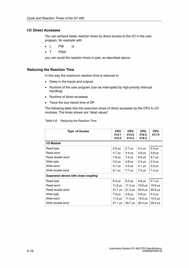
Cycle and Reaction Times of the S7-400
5-16Automation System S7-400 CPU Specifications
A5E00267840-03
I/O Direct Accesses
You can achieve faster reaction times by direct access to the I/O in the userprogram, for example with
• L PIB or
• T PQW
you can avoid the reaction times in part, as described above.
Reducing the Reaction Time
In this way the maximum reaction time is reduced to
• Delay in the inputs and outputs
• Runtime of the user program (can be interrupted by high-priority interrupthandling)
• Runtime of direct accesses
• Twice the bus transit time of DP
The following table lists the execution times of direct accesses by the CPU to I/Omodules. The times shown are “ideal values”.
Table 5-6 Reducing the Reaction Time
Type of Access CPU412-1412-2
CPU414-2414-3
CPU416-2416-3
CPU417-4
I/O Module
Read byte
Read word
Read double word
Write byte
Write word
Write double word
3.0 μs
4.7 μs
7.6 μs
3.2 μs
4.7 μs
8.1 μs
2.7 μs
4.4 μs
7.2 μs
2.8 μs
4.5 μs
7.7 μs
2.4 μs
3.9 μs
6.9 μs
2.4 μs
4.1 μs
7.3 μs
2.3 μs
3.8 μs
6.7 μs
2.3 μs
4.0 μs
7.2 μs
Expansion device with close coupling
Read byte
Read word
Read double word
Write byte
Write word
Write double word
6.4 μs
11.8 μs
21.7 μs
7.9 μs
11.2 μs
21.1 μs
6.2 μs
11.3 μs
21.3 μs
5.8 μs
11.0 μs
20.7 μs
5.8 μs
10.9 μs
20.9 μs
5.6 μs
10.6 μs
20.4 μs
5.7 μs
10.8 μs
20.8 μs
5.5 μs
10.5 μs
20.2 μs
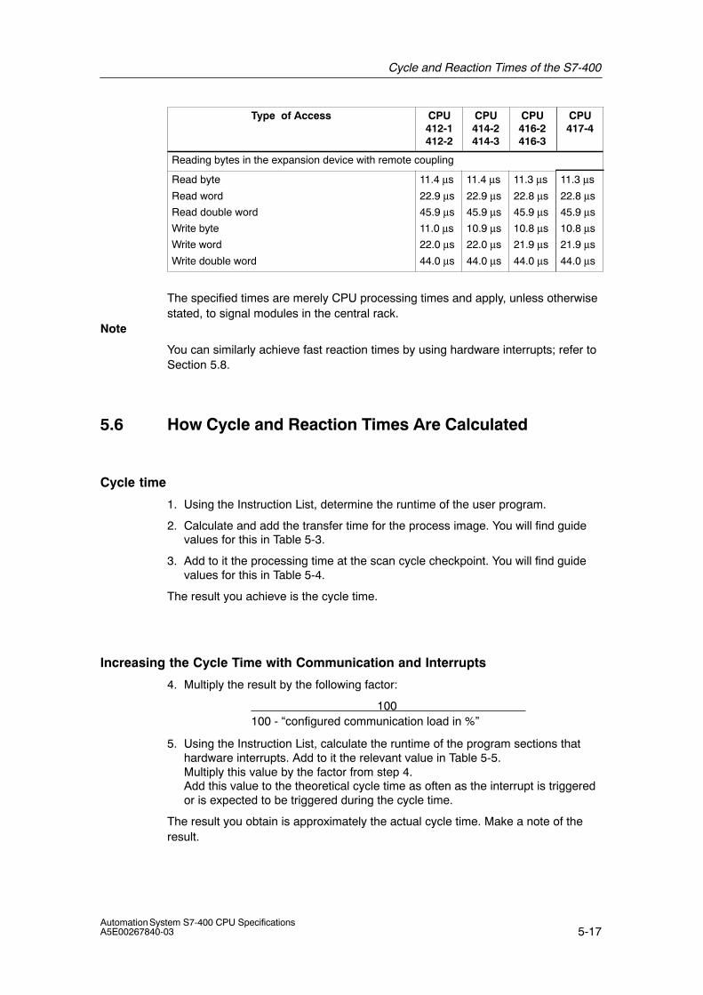
Cycle and Reaction Times of the S7-400
5-17Automation System S7-400 CPU SpecificationsA5E00267840-03
Type of Access CPU417-4
CPU416-2416-3
CPU414-2414-3
CPU412-1412-2
Reading bytes in the expansion device with remote coupling
Read byte
Read word
Read double word
Write byte
Write word
Write double word
11.4 μs
22.9 μs
45.9 μs
11.0 μs
22.0 μs
44.0 μs
11.4 μs
22.9 μs
45.9 μs
10.9 μs
22.0 μs
44.0 μs
11.3 μs
22.8 μs
45.9 μs
10.8 μs
21.9 μs
44.0 μs
11.3 μs
22.8 μs
45.9 μs
10.8 μs
21.9 μs
44.0 μs
The specified times are merely CPU processing times and apply, unless otherwisestated, to signal modules in the central rack.
Note
You can similarly achieve fast reaction times by using hardware interrupts; refer toSection 5.8.
5.6 How Cycle and Reaction Times Are Calculated
Cycle time
1. Using the Instruction List, determine the runtime of the user program.
2. Calculate and add the transfer time for the process image. You will find guidevalues for this in Table 5-3.
3. Add to it the processing time at the scan cycle checkpoint. You will find guidevalues for this in Table 5-4.
The result you achieve is the cycle time.
Increasing the Cycle Time with Communication and Interrupts
4. Multiply the result by the following factor:
100 100 - “configured communication load in %”
5. Using the Instruction List, calculate the runtime of the program sections thathardware interrupts. Add to it the relevant value in Table 5-5. Multiply this value by the factor from step 4.Add this value to the theoretical cycle time as often as the interrupt is triggeredor is expected to be triggered during the cycle time.
The result you obtain is approximately the actual cycle time. Make a note of theresult.
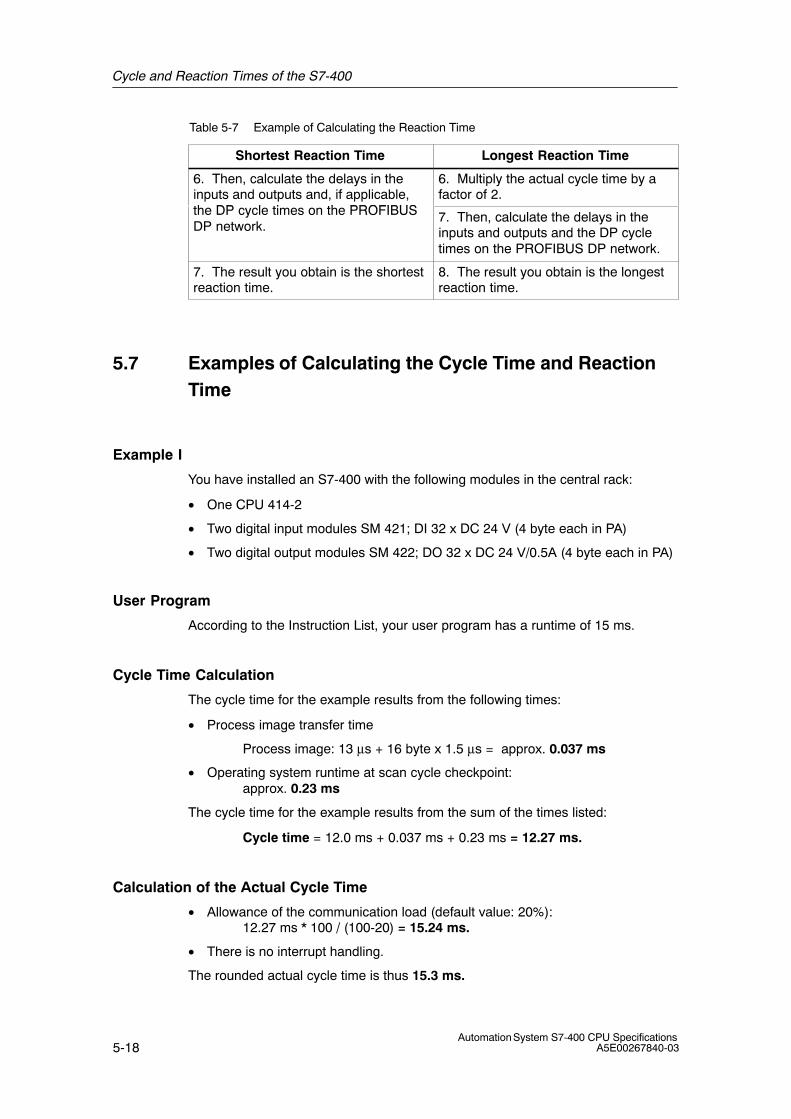
Cycle and Reaction Times of the S7-400
5-18Automation System S7-400 CPU Specifications
A5E00267840-03
Table 5-7 Example of Calculating the Reaction Time
Shortest Reaction Time Longest Reaction Time
6. Then, calculate the delays in theinputs and outputs and, if applicable,h DP l i h PROFIBUS
6. Multiply the actual cycle time by afactor of 2.
the DP cycle times on the PROFIBUSDP network.
7. Then, calculate the delays in theinputs and outputs and the DP cycletimes on the PROFIBUS DP network.
7. The result you obtain is the shortestreaction time.
8. The result you obtain is the longestreaction time.
5.7 Examples of Calculating the Cycle Time and ReactionTime
Example I
You have installed an S7-400 with the following modules in the central rack:
• One CPU 414-2
• Two digital input modules SM 421; DI 32 x DC 24 V (4 byte each in PA)
• Two digital output modules SM 422; DO 32 x DC 24 V/0.5A (4 byte each in PA)
User Program
According to the Instruction List, your user program has a runtime of 15 ms.
Cycle Time Calculation
The cycle time for the example results from the following times:
• Process image transfer time
Process image: 13 μs + 16 byte x 1.5 μs = approx. 0.037 ms
• Operating system runtime at scan cycle checkpoint: approx. 0.23 ms
The cycle time for the example results from the sum of the times listed:
Cycle time = 12.0 ms + 0.037 ms + 0.23 ms = 12.27 ms.
Calculation of the Actual Cycle Time
• Allowance of the communication load (default value: 20%): 12.27 ms * 100 / (100-20) = 15.24 ms.
• There is no interrupt handling.
The rounded actual cycle time is thus 15.3 ms.
Cycle and Reaction Times of the S7-400
5-19Automation System S7-400 CPU SpecificationsA5E00267840-03
Calculation of the Longest Reaction Time
• Longest reaction time 15.3 ms * 2 = 30.6 ms.
• The delay in the inputs and outputs is negligible.
• All the components are plugged into the central rack; DP cycle times do nottherefore have to be taken into account.
• There is no interrupt handling.
Rounded off, the longest reaction time is thus = 31 ms.
Example II
You have installed an S7-400 with the following modules:
• One CPU 414-2
• Four digital input modules SM 421; DI 32 x DC 24 V (4 byte each in PA)
• Three digital output modules SM 422; DO 16 x DC 24 V/2A (2 byte each in PA)
• Two analog input modules SM 431; AI 8 x 13 bit (not in PA)
• Two analog output modules SM 432; AO 8 x 13 bit (not in PA)
CPU Parameters
The CPU has been assigned parameters as follows:
• Cycle load due to communications: 40%
User Program
According to the Instruction List, the user program has a runtime of 10.0 ms.
Cycle Time Calculation
The theoretical cycle time for the example results from the following times:
• Process image transfer time
Process image: 13 μs + 22 byte x 1.5 μs = approx. 0.049 ms
• Operating system runtime at scan cycle checkpoint: approx. 0.23 ms
The cycle time for the example results from the sum of the times listed:
Cycle time = 10.0 ms + 0.049 ms + 0.23 ms = 10.28 ms.
Cycle and Reaction Times of the S7-400
5-20Automation System S7-400 CPU Specifications
A5E00267840-03
Calculation of the Actual Cycle Time
• Allowance of communication load: 10.28 ms * 100 / (100-40) = 37 ms.
• A time-of-day interrupt having a runtime of 0.5 ms is triggered every 100 ms.The interrupt cannot be triggered more than once during a cycle:
0.5 ms + 0.35 ms (in Table 5-5) = 0.85 ms.Allowance for communication load:
0.85 ms * 100 / (100-40) = 1.42 ms.
• 17.1 ms + 1.42 ms = 18.52 ms.
The actual cycle time is therefore 18.5 ms taking into account the time slices.
Calculation of the Longest Reaction Time
• Longest reaction time 8.5 ms * 2 = 37 ms.
• Delays in the inputs and outputs
– The digital input module SM 421; DI 32 x DC 24 V has an input delay of notmore than 4,8 ms per channel
– The digital output module SM 422; DO 16 x DC 24 V/2A has a negligibleoutput delay.
– The analog input module SM 431; AI 8 x 13 bit was assigned parameters for50 Hz interference frequency suppression. This results in a conversion timeof 25 ms per channel. Since 8 channels are active, a cycle time of 200 msresults for the analog input module.
– Analog output module SM 432; AO 8 x 13 bit was assigned parameters forthe measuring range from 0 to 10V. This results in a conversion time of0.3 ms per channel. Since 8 channels are active, a cycle time of 2.4 msresults. To this must be added the settling time for the resistive load, whichis 0.1 ms. A response time of 2.5 ms therefore results for an analog output.
• All the components are plugged into the central rack; DP cycle times do nottherefore have to be taken into account.
• Case 1: When a digital signal is read in, an output channel of the digital outputmodule is set. This produces a reaction time of:
Reaction time= 37 ms + 4.8 ms = 41.8 ms.
• Case 2: An analog value is read in and an analog value output. This produces areaction time of:
Reaction time = 37 ms + 200 ms + 2.5 ms = 239.5 ms.
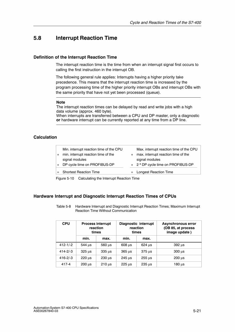
Cycle and Reaction Times of the S7-400
5-21Automation System S7-400 CPU SpecificationsA5E00267840-03
5.8 Interrupt Reaction Time
Definition of the Interrupt Reaction Time
The interrupt reaction time is the time from when an interrupt signal first occurs tocalling the first instruction in the interrupt OB.
The following general rule applies: Interrupts having a higher priority takeprecedence. This means that the interrupt reaction time is increased by theprogram processing time of the higher priority interrupt OBs and interrupt OBs withthe same priority that have not yet been processed (queue).
NoteThe interrupt reaction times can be delayed by read and write jobs with a highdata volume (approx. 460 byte).When interrupts are transferred between a CPU and DP master, only a diagnosticor hardware interrupt can be currently reported at any time from a DP line.
Calculation
Min. interrupt reaction time of the CPU+ min. interrupt reaction time of the
signal modules+ DP cycle time on PROFIBUS-DP
= Shortest Reaction Time
Max. interrupt reaction time of the CPU + max. interrupt reaction time of the
signal modules+ 2 * DP cycle time on PROFIBUS-DP
= Longest Reaction Time
Figure 5-10 Calculating the Interrupt Reaction Time
Hardware Interrupt and Diagnostic Interrupt Reaction Times of CPUs
Table 5-8 Hardware Interrupt and Diagnostic Interrupt Reaction Times; Maximum InterruptReaction Time Without Communication
CPU Process interruptreaction
times
Diagnostic interruptreaction
times
Asynchronous error(OB 85, at process
image update )
min. max. min. max.
412-1/-2 544 μs 560 μs 608 μs 624 μs 392 μs
414-2/-3 325 μs 335 μs 365 μs 375 μs 300 μs
416-2/-3 220 μs 230 μs 245 μs 255 μs 200 μs
417-4 200 μs 210 μs 225 μs 235 μs 180 μs
Cycle and Reaction Times of the S7-400
5-22Automation System S7-400 CPU Specifications
A5E00267840-03
Increasing the Maximum Interrupt Reaction Time with Communication
The maximum interrupt reaction time increases when communication functions areactive. The increase is calculated with the following formula:
CPU 412: tv = 200 μs + 1000 μs x n%
CPU 414-417: tv = 100 μs + 1000 μs x n%
where n = cycle load from communication
Signal Modules
The hardware interrupt reaction time of the signal modules is made up as follows:
• Digital input modules
Hardware interrupt reaction time = internal interrupt processing time + inputdelay
You will find the times in the data sheet of the digital input module concerned.
• Analog input modules
Hardware interrupt reaction time = internal interrupt processing time +conversion time
The internal interrupt processing time of the analog input modules is negligible.The conversion times can be taken from the data sheet of the analog inputmodule concerned.
The diagnostic interrupt reaction time of the signal modules is the time whichelapses between a diagnostics event being detected by the signal module and thediagnostic interrupt being triggered by the signal module. This time is so small thatit can be ignored.
Hardware Interrupt Processing
When the hardware interrupt OB 40 is called, the hardware interrupt is processed.Interrupts with higher priority interrupt hardware interrupt processing, and directaccess to the I/O is made when the instruction is executed. When hardwareinterrupt processing is completed, either cyclic program processing is continued orother interrupt OBs with the same or a lower priority are called and processed.
Cycle and Reaction Times of the S7-400
5-23Automation System S7-400 CPU SpecificationsA5E00267840-03
5.9 Example of Calculating the Interrupt Reaction Time
Parts of the Interrupt Reaction Time
As a reminder, the hardware interrupt reaction time is made up of the following:
• Hardware interrupt reaction time of the CPU
• Hardware interrupt reaction time of the signal module.
• 2 × DP cycle time on the PROFIBUS-DP
Example: You have an S7-400 consisting of a CPU 416-2 and 4 digital modules inthe central rack. One digital input module is the SM 421; DI 16×UC 24/60 V; withhardware and diagnostic interrupts. In the parameter assignment of the CPU andthe SM, you have only enabled the hardware interrupt. You do not requiretime-driven processing, diagnostics and error handling. You have assigned an inputdelay of 0.5 ms for the digital input module. No activities at the scan cyclecheckpoint are required. You have set a cycle load from communication of 20%.
Calculation
The hardware interrupt reaction time for the example results from the followingtimes:
• Hardware interrupt reaction time of the CPU 416-2: approx. 0.35 ms
• Increase from communication in accordance with the formula shown inTable 5-8 :
100 μs + 1000 μs x 20% = 300 μs = 0.3 ms
• Hardware interrupt reaction time of the SM 421; DI 16 x UC 24/60 V:
– Internal interrupt processing time: 0.5 ms
– Input delay: 0.5 ms
• Since the signal modules are plugged into the central rack, the DP cycle timeon the PROFIBUS-DP is not relevant.
The hardware interrupt reaction time results from the sum of the listed times:
Hardware interrupt reaction time = 0.23 ms +0.3 ms + 0.5 ms + 0.5 ms = approx.1.53 ms.
This calculated hardware interrupt reaction time is the time from a signal beingapplied across the digital input to the first instruction in OB 40.
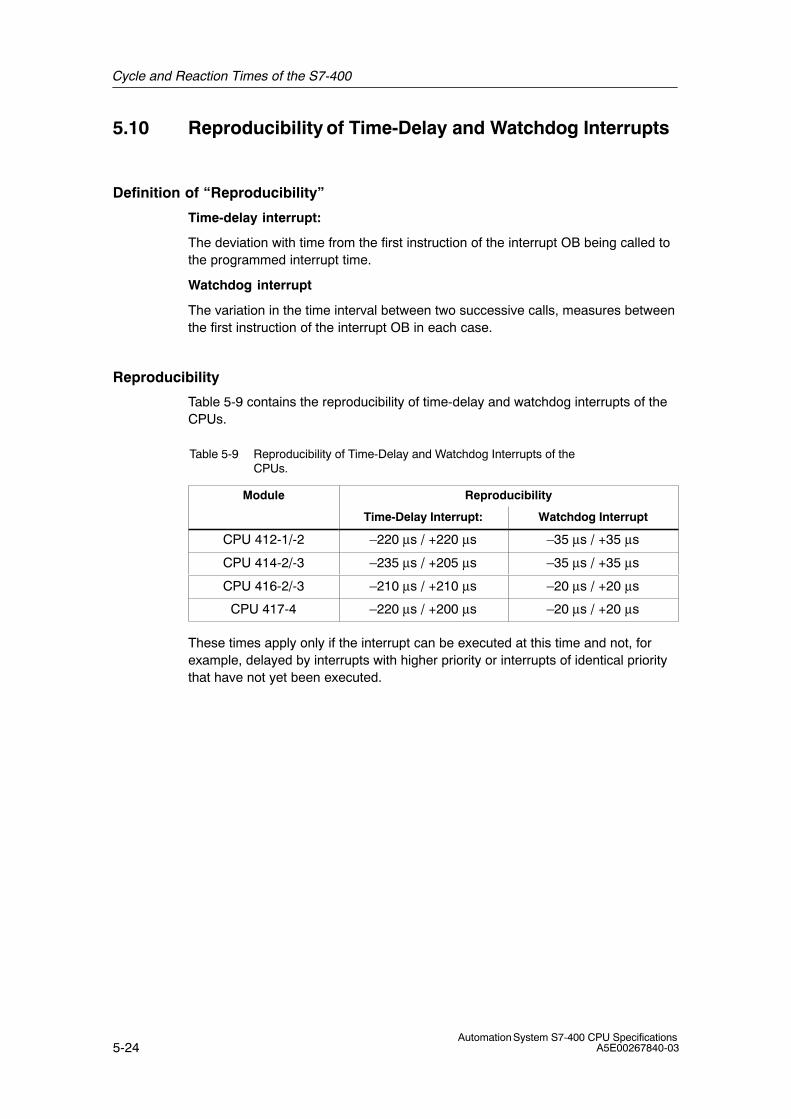
Cycle and Reaction Times of the S7-400
5-24Automation System S7-400 CPU Specifications
A5E00267840-03
5.10 Reproducibility of Time-Delay and Watchdog Interrupts
Definition of “Reproducibility”
Time-delay interrupt:
The deviation with time from the first instruction of the interrupt OB being called tothe programmed interrupt time.
Watchdog interrupt
The variation in the time interval between two successive calls, measures betweenthe first instruction of the interrupt OB in each case.
Reproducibility
Table 5-9 contains the reproducibility of time-delay and watchdog interrupts of theCPUs.
Table 5-9 Reproducibility of Time-Delay and Watchdog Interrupts of theCPUs.
Module Reproducibility
Time-Delay Interrupt: Watchdog Interrupt
CPU 412-1/-2 –220 μs / +220 μs –35 μs / +35 μs
CPU 414-2/-3 –235 μs / +205 μs –35 μs / +35 μs
CPU 416-2/-3 –210 μs / +210 μs –20 μs / +20 μs
CPU 417-4 –220 μs / +200 μs –20 μs / +20 μs
These times apply only if the interrupt can be executed at this time and not, forexample, delayed by interrupts with higher priority or interrupts of identical prioritythat have not yet been executed.
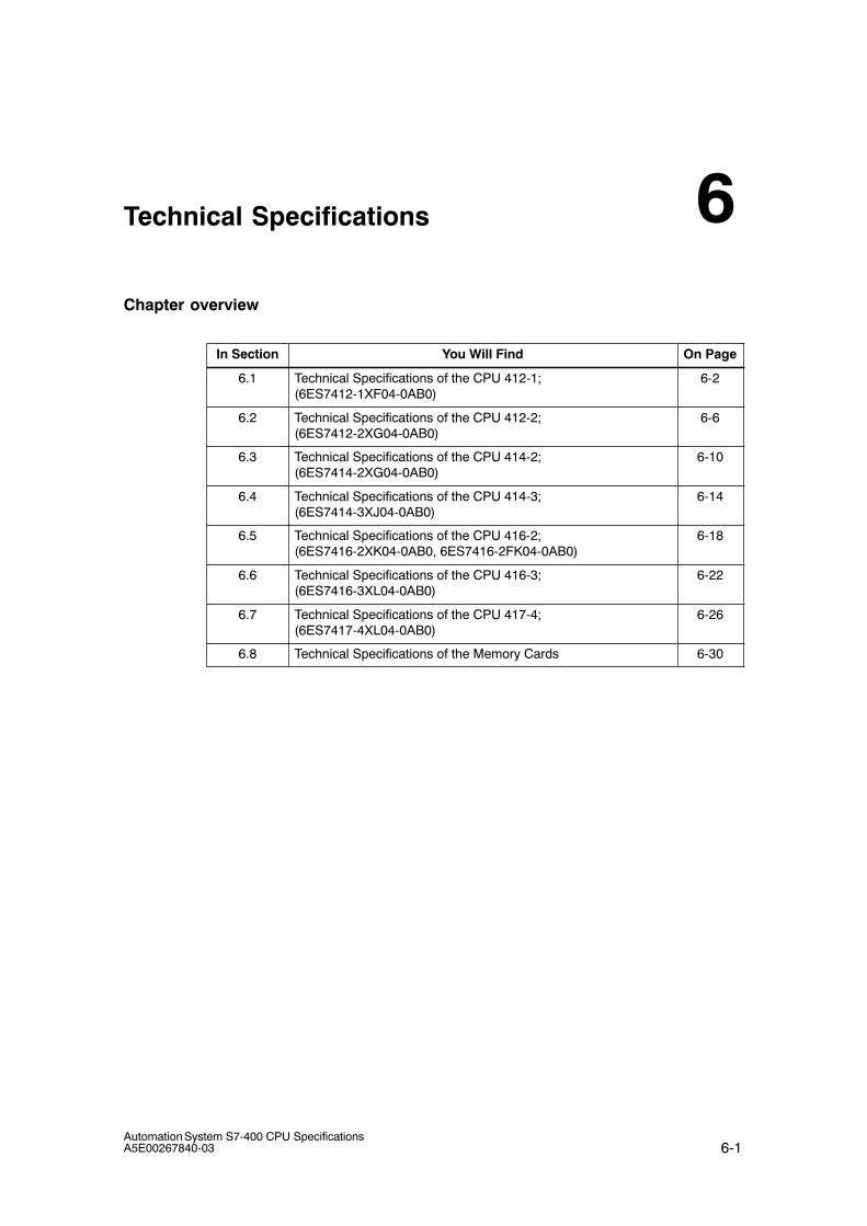
6-1Automation System S7-400 CPU SpecificationsA5E00267840-03
Technical Specifications
Chapter overview
In Section You Will Find On Page
6.1 Technical Specifications of the CPU 412-1;(6ES7412-1XF04-0AB0)
6-2
6.2 Technical Specifications of the CPU 412-2;(6ES7412-2XG04-0AB0)
6-6
6.3 Technical Specifications of the CPU 414-2;(6ES7414-2XG04-0AB0)
6-10
6.4 Technical Specifications of the CPU 414-3;(6ES7414-3XJ04-0AB0)
6-14
6.5 Technical Specifications of the CPU 416-2; (6ES7416-2XK04-0AB0, 6ES7416-2FK04-0AB0)
6-18
6.6 Technical Specifications of the CPU 416-3;(6ES7416-3XL04-0AB0)
6-22
6.7 Technical Specifications of the CPU 417-4;(6ES7417-4XL04-0AB0)
6-26
6.8 Technical Specifications of the Memory Cards 6-30
6

Technical Specifications
6-2Automation System S7-400 CPU Specifications
A5E00267840-03
6.1 Technical Specifications of the CPU 412-1; (6ES7412-1XF04-0AB0)
CPU and Firmware VersionMLFB 6ES7412-1XF04-0AB0
• Firmware version 4.0.0
Associated programmingpackage
As of STEP 7 5.2 SP1HF3 with HW update
Memory
Working memory
• Integrated 72 Kbytes for code72 Kbytes for data
Load memory
• Integrated 256 Kbytes RAM
• Expandable FEPROM With memory card(FLASH) up to 64 Mbytes
• Expandable RAM With memory card (RAM)up to 64 Mbytes
Backup with battery Yes, all data
Processing Times
Processing times for
• Bit operations 0.1 μs
• Word instructions 0.1 μs
• Integer math instructions 0.1 μs
• Floating-point mathinstructions
0.3 μs
Timers/Counters and Their Retentivity
S7 counters 2048
• Retentivity can be set From Z 0 to Z 2047
• Preset From Z 0 to Z 7
• Counting range 1 to 999
IEC counter Yes
• Type SFB
S7 timers 2048
• Retentivity can be set From T 0 to T 2047
• Preset No retentive timers
• Time range 10 ms to 9990 s
IEC timers Yes
• Type SFB
Data Areas and Their RetentivityTotal retentive data areas(including memory bits;times; counts)
Total working and loadmemory (with backupbattery)
Memory markers 4 Kbytes
• Retentivity can be set From MB 0 to MB 4095
• Preset retentivity From MB 0 to MB 15
Clock memories 8 (1 memory byte)
Data blocks Max. 511 (DB 0 reserved)
• Size Max. 64 Kbytes
Local data (can be set) Max. 8 Kbytes
• Preset 4 Kbytes
Blocks
OBs See instruction list
• Size Limited by workingmemory
Nesting depth
• Per priority class 24
• Additionally in an errorOB
2
FBs Max. 256
• Size Limited by workingmemory
FCs Max. 256
• Size Limited by workingmemory
Address Areas (Inputs/Outputs)
Total I/O address area 4 Kbytes/4 Kbytes
• Of which distributed
MPI/DP interface 2 Kbytes/2 Kbytes
Process Image 4 Kbytes/4 Kbytes (canbe set)
• Preset 128 bytes/128 bytes
• Number of partialprocess images
Max. 15
• Consistent data Max. 244 bytes
Digital channels Max. 32768/Max. 32768
• Of which central Max. 32768/Max. 32768
Analog channels Max. 2048/Max. 2048
• Of which central Max. 2048/Max. 2048

Technical Specifications
6-3Automation System S7-400 CPU SpecificationsA5E00267840-03
ConfigurationCentral racks/expansionunits
Max. 1/21
Multicomputing Max. 4 CPUs (with UR1 or UR2)
Number of plug-in IMs(overall)
Max. 6
• IM 460 Max. 6
• IM 463-2 Max. 4
Number of DP masters
• Integrated 1
• Via IM 467 Max. 4
• Via CP 443-5 Extended Max. 10
IM 467 cannot be used with the CP 443-5 EX40
IM 467 cannot be used with the CP 443-1 EX40 in PN IOmode
Number of plug-in S5modules via adapter casing(in the central rack)
Max. 6
Operable function modulesand communicationprocessors
• FM Limited by the number ofslots and the number ofconnections
• CP 440 Limited by the number ofslots
• CP 441 Limited by the number ofconnections
• PROFIBUS and EthernetCPs incl. CP 443-5Extended and IM 467
Max. 14
Time
Clock Yes
• Buffered Yes
• Resolution 1 ms
• Accuracy at
– Power off Deviation per day 1.7 s
– Power on Deviation per day 8.6 s
Runtime meter 8
• Number 0 to 7
• Value Range 0 to 32767 hours
• Granularity 1 hour
• Retentive Yes
Time synchronization Yes
• In PLC, on MPI and DP as master or slave
S7 Message FunctionsNumber of stations that canlog on for messagefunctions (e.g. WIN CC orSIMATIC OP)
Max. 8
Symbol-related messages Yes
• Number of messages
– Overall
– 100 ms grid
– 500 ms grid
– 1000 ms grid
Max. 512
None
Max. 256
Max. 256
• Number of additionalvalues per message
1
– With 100 ms grid None
– With 500, 1000 msgrid
1
Block-related messages Yes
• Simultaneously activeALARM_S/SQ blocksand ALARM_D/DQblocks
Max. 70
ALARM_8 blocks Yes
• Number ofcommunication jobs forALARM_8 blocks andblocks for S7communication (can beset)
Max. 300
• Preset 150
Process control reports Yes
Number of archives thatcan log on simultaneously(SFB 37 AR_SEND)
4
Test and Commissioning Functions
Monitor/modify variable Yes
• Variables Inputs/outputs, memorymarkers, DB, distributedinputs/outputs, timers,counters
• Number of variables Max. 70
Force Yes
• Variables Inputs/outputs, memorymarkers, distributedinputs/outputs
• Number of variables Max. 64
Status block Yes
Single sequence Yes
Diagnostic buffer Yes
• Number of entries Max. 200 (can be set)
• Preset 120
Number of breakpoints 4
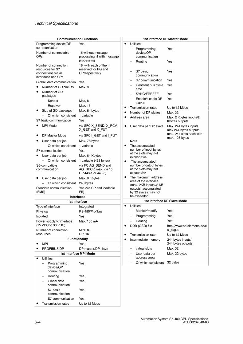
Technical Specifications
6-4Automation System S7-400 CPU Specifications
A5E00267840-03
Communication FunctionsProgramming device/OPcommunication
Yes
Number of connectableOPs
15 without messageprocessing, 8 with messageprocessing
Number of connectionresources for S7connections via allinterfaces and CPs
16, with each of themreserved for PG andOPrespectively
Global data communication Yes
• Number of GD circuits Max. 8
• Number of GDpackages
– Sender Max. 8
– Receiver Max. 16
• Size of GD packages Max. 64 bytes
– Of which consistent 1 variable
S7 basic communication Yes
• MPI Mode via SFC X_SEND, X_RCV,X_GET and X_PUT
• DP Master Mode via SFC I_GET and I_PUT
• User data per job Max. 76 bytes
– Of which consistent 1 variable
S7 communication Yes
• User data per job Max. 64 Kbytes
– Of which consistent 1 variable (462 bytes)
S5-compatiblecommunication
via FC AG_SEND andAG_RECV, max. via 10CP 443-1 or 443-5)
• User data per job Max. 8 Kbytes
– Of which consistent 240 bytes
Standard communication(FMS)
Yes (via CP and loadableFB)
Interfaces1st Interface
Type of interface Integrated
Physical RS 485/Profibus
Isolated Yes
Power supply to interface(15 VDC to 30 VDC)
Max. 150 mA
Number of connectionresources
MPI: 16DP: 16
Functionality
• MPI Yes
• PROFIBUS DP DP master/DP slave
1st Interface MPI Mode
• Utilities
– Programmingdevice/OPcommunication
Yes
– Routing Yes
– Global datacommunication
Yes
– S7 basiccommunication
Yes
– S7 communication Yes
• Transmission rates Up to 12 Mbps
1st Interface DP Master Mode• Utilities
– Programmingdevice/OPcommunication
Yes
– Routing Yes
– S7 basiccommunication
Yes
– S7 communication Yes
– Constant bus cycletime
Yes
– SYNC/FREEZE Yes
– Enable/disable DPslaves
Yes
• Transmission rates Up to 12 Mbps
• Number of DP slaves Max. 32
• Address area Max. 2 Kbytes inputs/2Kbytes outputs
• User data per DP slave
Note:• The accumulated
number of input bytesat the slots may notexceed 244
• The accumulatednumber of output bytesat the slots may notexceed 244
• The maximum addressarea of the interface(max. 2KB inputs /2 KBoutputs) accumulatedby 32 slaves may notbe exceeded
Max. 244 bytes inputs,max.244 bytes outputs,max. 244 slots each withmax. 128 bytes
1st Interface DP Slave Mode
• Utilities
– Monitor/modify
– Programming
– Routing
Yes
Yes
Yes
• DDB (GSD) file http://www.ad.siemens.de/csi_e/gsd
• Transmission rate Up to 12 Mbps
• Intermediate memory 244 bytes inputs/244 bytes outputs
– virtual slots
– User data peraddress area
– Of which consistent
Max. 32
Max. 32 bytes
32 bytes

Technical Specifications
6-5Automation System S7-400 CPU SpecificationsA5E00267840-03
ProgrammingProgramming language LAD, FBD, STL, SCL
Instruction set See instruction list
Bracket levels 8
System functions (SFC) See instruction list
Number of SFCs active atthe same time for everystrand
• DPSYC_FR 2
• D_ACT_DP 4
• RD_REC 8
• WR_REC 8
• WR_PARM 8
• PARM_MOD 1
• WR_DPARM 2
• DPNRM_DG 8
• RDSYSST 1 to 8
• DP_TOPOL 1
System function blocks(SFB)
See instruction list
Number of SFBs active atthe same time
• RD_REC 8
• WR_REC 8
User program protection Password protection
Access to consistent datain the process image
Yes
Clock synchronism
User data per clocksynchronous slave
Max. 244 bytes
Maximum number of bytesand slaves in a processimage partition
The following applies:
Number of bytes/100 +number of slaves <16
Constant bus cycle time Yes
Shortest clock pulse
see the manual ClockSynchronism
1.5 ms
0.5 ms without use ofSFC 126, 127
CiR synchronization time
Base load 100 ns
Time per I/O byte 200 μs
DimensionsMounting dimensionsW×H×D (mm)
25×290×219
Slots required 1
Weight approx. 0.72 kg
Voltages, Currents
Current consumption fromS7-400 bus (5 VDC)
Typ. 0.6 A
Max. 0.7 A
Current consumption fromthe S7-400 bus (24 VDC)The CPU does notconsume any current at24 V, and it only makes thisvoltage available at theMPI/DP interface.
Total current consumptionof the componentsconnected to the MPI/DPinterfaces, with a maximumof 150 mA per interface
Backup current Typ. 350 μA
Max. 890 μA
maximum backup time See manual ModuleSpecifications, chapter 3.3
Incoming supply of externalbackup voltage to the CPU
5 VDC to 15 VDC
Power loss Typ. 3.0 W
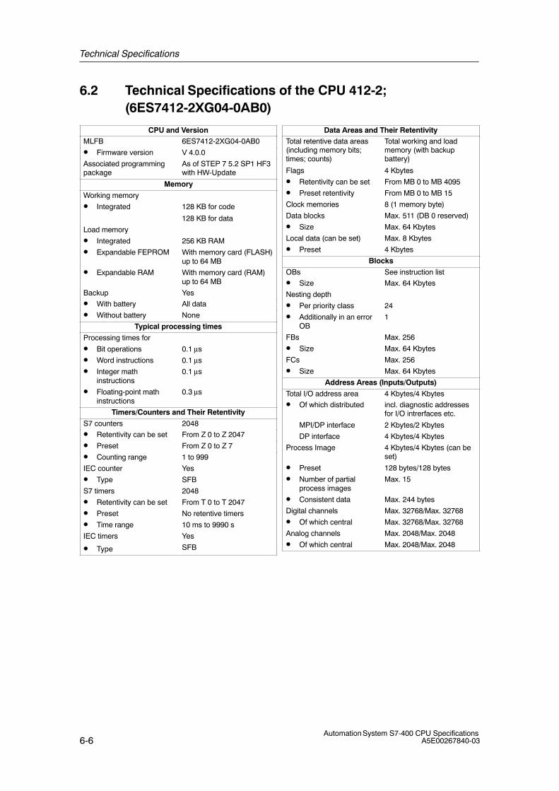
Technical Specifications
6-6Automation System S7-400 CPU Specifications
A5E00267840-03
6.2 Technical Specifications of the CPU 412-2; (6ES7412-2XG04-0AB0)
CPU and VersionMLFB 6ES7412-2XG04-0AB0
• Firmware version V 4.0.0
Associated programmingpackage
As of STEP 7 5.2 SP1 HF3with HW-Update
Memory
Working memory
• Integrated 128 KB for code
128 KB for data
Load memory
• Integrated 256 KB RAM
• Expandable FEPROM With memory card (FLASH)up to 64 MB
• Expandable RAM With memory card (RAM)up to 64 MB
Backup Yes
• With battery All data
• Without battery None
Typical processing times
Processing times for
• Bit operations 0.1 μs
• Word instructions 0.1 μs
• Integer mathinstructions
0.1 μs
• Floating-point mathinstructions
0.3 μs
Timers/Counters and Their Retentivity
S7 counters 2048
• Retentivity can be set From Z 0 to Z 2047
• Preset From Z 0 to Z 7
• Counting range 1 to 999
IEC counter Yes
• Type SFB
S7 timers 2048
• Retentivity can be set From T 0 to T 2047
• Preset No retentive timers
• Time range 10 ms to 9990 s
IEC timers Yes
• Type SFB
Data Areas and Their RetentivityTotal retentive data areas(including memory bits;times; counts)
Total working and loadmemory (with backupbattery)
Flags 4 Kbytes
• Retentivity can be set From MB 0 to MB 4095
• Preset retentivity From MB 0 to MB 15
Clock memories 8 (1 memory byte)
Data blocks Max. 511 (DB 0 reserved)
• Size Max. 64 Kbytes
Local data (can be set) Max. 8 Kbytes
• Preset 4 Kbytes
Blocks
OBs See instruction list
• Size Max. 64 Kbytes
Nesting depth
• Per priority class 24
• Additionally in an errorOB
1
FBs Max. 256
• Size Max. 64 Kbytes
FCs Max. 256
• Size Max. 64 Kbytes
Address Areas (Inputs/Outputs)
Total I/O address area 4 Kbytes/4 Kbytes
• Of which distributed incl. diagnostic addressesfor I/O intrerfaces etc.
MPI/DP interface 2 Kbytes/2 Kbytes
DP interface 4 Kbytes/4 Kbytes
Process Image 4 Kbytes/4 Kbytes (can beset)
• Preset 128 bytes/128 bytes
• Number of partialprocess images
Max. 15
• Consistent data Max. 244 bytes
Digital channels Max. 32768/Max. 32768
• Of which central Max. 32768/Max. 32768
Analog channels Max. 2048/Max. 2048
• Of which central Max. 2048/Max. 2048

Technical Specifications
6-7Automation System S7-400 CPU SpecificationsA5E00267840-03
ConfigurationCentral racks/expansionunits
Max. 1/21
Multicomputing Max. 4 CPUs (with UR1 or UR2)
Number of plug-in IMs(overall)
Max. 6
• IM 460 Max. 6
• IM 463-2 Max. 4
Number of DP masters
• Integrated 2
• Via IM 467 Max. 4
• Via CP 443-5 Extended Max. 10
IM 467 cannot be used with the CP 443-5 Extended
IM 467 cannot be used with the CP 443-1 EX40 in PN IOmode
Number of plug-in S5modules via adapter casing(in the central rack)
Max. 6
Operable function modulesand communicationprocessors
• FM Limited by the number ofslots and the number ofconnections
• CP 440 Limited by the number ofslots
• CP 441 Limited by the number ofconnections
• Profibus and EthernetCPs incl. CP 443-5Extended and IM 467
Max. 14
Time
Clock Yes
• Buffered Yes
• Resolution 1 ms
• Accuracy at
– Power off Deviation per day 1.7 s
– Power on Deviation per day 8.6 s
Runtime meter 8
• Number 0 to 7
• Value Range 0 to 32767 hours
• Granularity 1 hour
• Retentive Yes
Time synchronization Yes
• In PLC, on MPI and DP as master or slave
S7 Message FunctionsNumber of stations that canlog on for messagefunctions (e.g. WIN CC orSIMATIC OP)
Max. 8
Symbol-related messages Yes
• Number of messages
– Overall
– 100 ms grid
– 500 ms grid
– 1000 ms grid
Max. 512
None
Max. 256
Max. 256
• Number of additionalvalues per message
1
– With 100 ms grid None
– With 500, 1000 msgrid
1
Block-related messages Yes
• Simultaneously activeALARM_S/SQ blocksand ALARM_D/DQblocks
Max. 70
ALARM_8 blocks Yes
• Number ofcommunication jobs forALARM_8 blocks andblocks for S7communication (can beset)
Max. 300
• Default 150
Process control reports Yes
Number of archives thatcan log on simultaneously(SFB 37 AR_SEND)
4
Test and Startup Functions
Monitor/modify variable Yes
• Variables Inputs/outputs, memorymarkers, DB, distributedinputs/outputs, timers,counters
• Number of variables Max. 70
Force Yes
• Variables Inputs/outputs, memorymarkers, distributedinputs/outputs
• Quantity Max. 64
Status block Yes
Single sequence Yes
Diagnostic buffer Yes
• Number of entries Max. 400 (can be set)
• Preset 120
Number of breakpoints 4
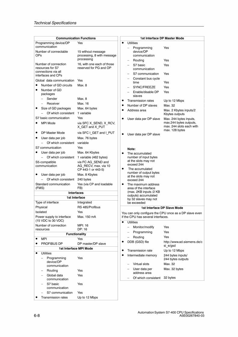
Technical Specifications
6-8Automation System S7-400 CPU Specifications
A5E00267840-03
Communication FunctionsProgramming device/OPcommunication
Yes
Number of connectableOPs
15 without messageprocessing, 8 with messageprocessing
Number of connectionresources for S7connections via allinterfaces and CPs
16, with one each of thosereserved for PG and OP
Global data communication Yes
• Number of GD circuits Max. 8
• Number of GDpackages
– Sender Max. 8
– Receiver Max. 16
• Size of GD packages Max. 64 bytes
– Of which consistent 1 variable
S7 basic communication Yes
• MPI Mode via SFC X_SEND, X_RCV,X_GET and X_PUT
• DP Master Mode via SFC I_GET and I_PUT
• User data per job Max. 76 bytes
– Of which consistent variable
S7 communication Yes
• User data per job Max. 64 Kbytes
– Of which consistent 1 variable (462 bytes)
S5-compatiblecommunication
via FC AG_SEND andAG_RECV, max. via 10CP 443-1 or 443-5)
• User data per job Max. 8 Kbytes
– Of which consistent 240 bytes
Standard communication(FMS)
Yes (via CP and loadableFB)
Interfaces1st Interface
Type of interface Integrated
Physical RS 485/Profibus
Isolated Yes
Power supply to interface(15 VDC to 30 VDC)
Max. 150 mA
Number of connectionresources
MPI: 16DP: 16
Functionality
• MPI Yes
• PROFIBUS DP DP master/DP slave
1st Interface MPI Mode
• Utilities
– Programmingdevice/OPcommunication
Yes
– Routing Yes
– Global datacommunication
Yes
– S7 basiccommunication
Yes
– S7 communication Yes
• Transmission rates Up to 12 Mbps
1st Interface DP Master Mode• Utilities
– Programmingdevice/OPcommunication
Yes
– Routing Yes
– S7 basiccommunication
Yes
– S7 communication Yes
– Constant bus cycletime Yes
– SYNC/FREEZE Yes
– Enable/disable DPslaves
Yes
• Transmission rates Up to 12 Mbps
• Number of DP slaves Max. 32
• Address area Max. 2 Kbytes inputs/2Kbytes outputs
• User data per DP slave
• User data per DP slave
Note:• The accumulated
number of input bytesat the slots may notexceed 244
• The accumulatednumber of output bytesat the slots may notexceed 244
• The maximum addressarea of the interface(max. 2KB inputs /2 KBoutputs) accumulatedby 32 slaves may notbe exceeded
Max. 244 bytes inputs,max.244 bytes outputs,max. 244 slots each withmax. 128 bytes
1st Interface DP Slave Mode
You can only configure the CPU once as a DP slave evenif the CPU has several interfaces.
• Utilities
– Monitor/modify
– Programming
– Routing
Yes
Yes
Yes
• DDB (GSD) file http://www.ad.siemens.de/csi_e/gsd
• Transmission rate Up to 12 Mbps
• Intermediate memory 244 bytes inputs/244 bytes outputs
– Virtual slots
– User data peraddress area
– Of which consistent
Max. 32
Max. 32 bytes
32 bytes
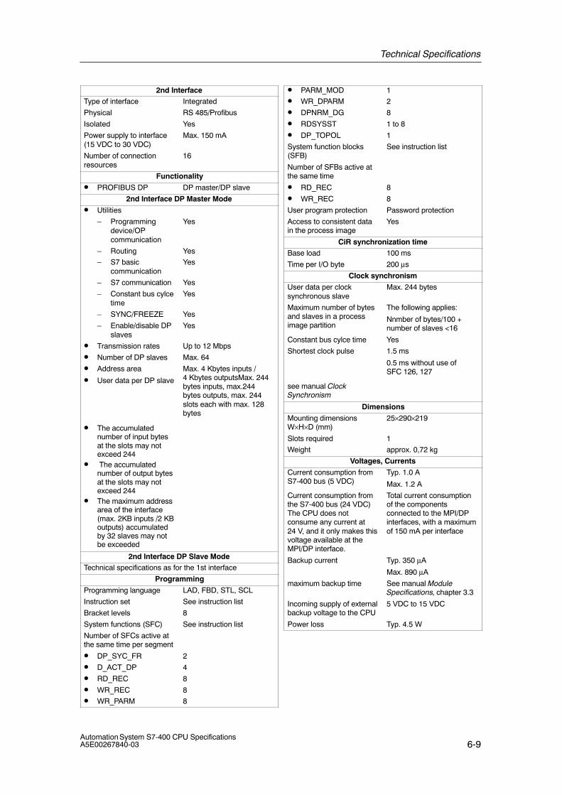
Technical Specifications
6-9Automation System S7-400 CPU SpecificationsA5E00267840-03
2nd InterfaceType of interface Integrated
Physical RS 485/Profibus
Isolated Yes
Power supply to interface(15 VDC to 30 VDC)
Max. 150 mA
Number of connectionresources
16
Functionality
• PROFIBUS DP DP master/DP slave
2nd Interface DP Master Mode
• Utilities
– Programmingdevice/OPcommunication
Yes
– Routing Yes
– S7 basiccommunication
Yes
– S7 communication Yes
– Constant bus cylcetime
Yes
– SYNC/FREEZE Yes
– Enable/disable DPslaves
Yes
• Transmission rates Up to 12 Mbps
• Number of DP slaves Max. 64
• Address area
• User data per DP slave
Max. 4 Kbytes inputs / 4 Kbytes outputsMax. 244bytes inputs, max.244bytes outputs, max. 244slots each with max. 128bytes
• The accumulatednumber of input bytesat the slots may notexceed 244
• The accumulatednumber of output bytesat the slots may notexceed 244
• The maximum addressarea of the interface(max. 2KB inputs /2 KBoutputs) accumulatedby 32 slaves may notbe exceeded
2nd Interface DP Slave ModeTechnical specifications as for the 1st interface
Programming
Programming language LAD, FBD, STL, SCL
Instruction set See instruction list
Bracket levels 8
System functions (SFC) See instruction list
Number of SFCs active atthe same time per segment
• DP_SYC_FR 2
• D_ACT_DP 4
• RD_REC 8
• WR_REC 8
• WR_PARM 8
• PARM_MOD 1
• WR_DPARM 2
• DPNRM_DG 8
• RDSYSST 1 to 8
• DP_TOPOL 1
System function blocks(SFB)
See instruction list
Number of SFBs active atthe same time
• RD_REC 8
• WR_REC 8
User program protection Password protection
Access to consistent datain the process image
Yes
CiR synchronization timeBase load 100 ms
Time per I/O byte 200 μs
Clock synchronism
User data per clocksynchronous slave
Max. 244 bytes
Maximum number of bytesand slaves in a processimage partition
The following applies:
Nnmber of bytes/100 +number of slaves <16
Constant bus cylce time Yes
Shortest clock pulse
see manual ClockSynchronism
1.5 ms
0.5 ms without use ofSFC 126, 127
Dimensions
Mounting dimensionsW×H×D (mm)
25×290×219
Slots required 1
Weight approx. 0,72 kg
Voltages, Currents
Current consumption fromS7-400 bus (5 VDC)
Typ. 1.0 A
Max. 1.2 A
Current consumption fromthe S7-400 bus (24 VDC)The CPU does notconsume any current at24 V, and it only makes thisvoltage available at theMPI/DP interface.
Total current consumptionof the componentsconnected to the MPI/DPinterfaces, with a maximumof 150 mA per interface
Backup current Typ. 350 μA
Max. 890 μA
maximum backup time See manual ModuleSpecifications, chapter 3.3
Incoming supply of externalbackup voltage to the CPU
5 VDC to 15 VDC
Power loss Typ. 4.5 W
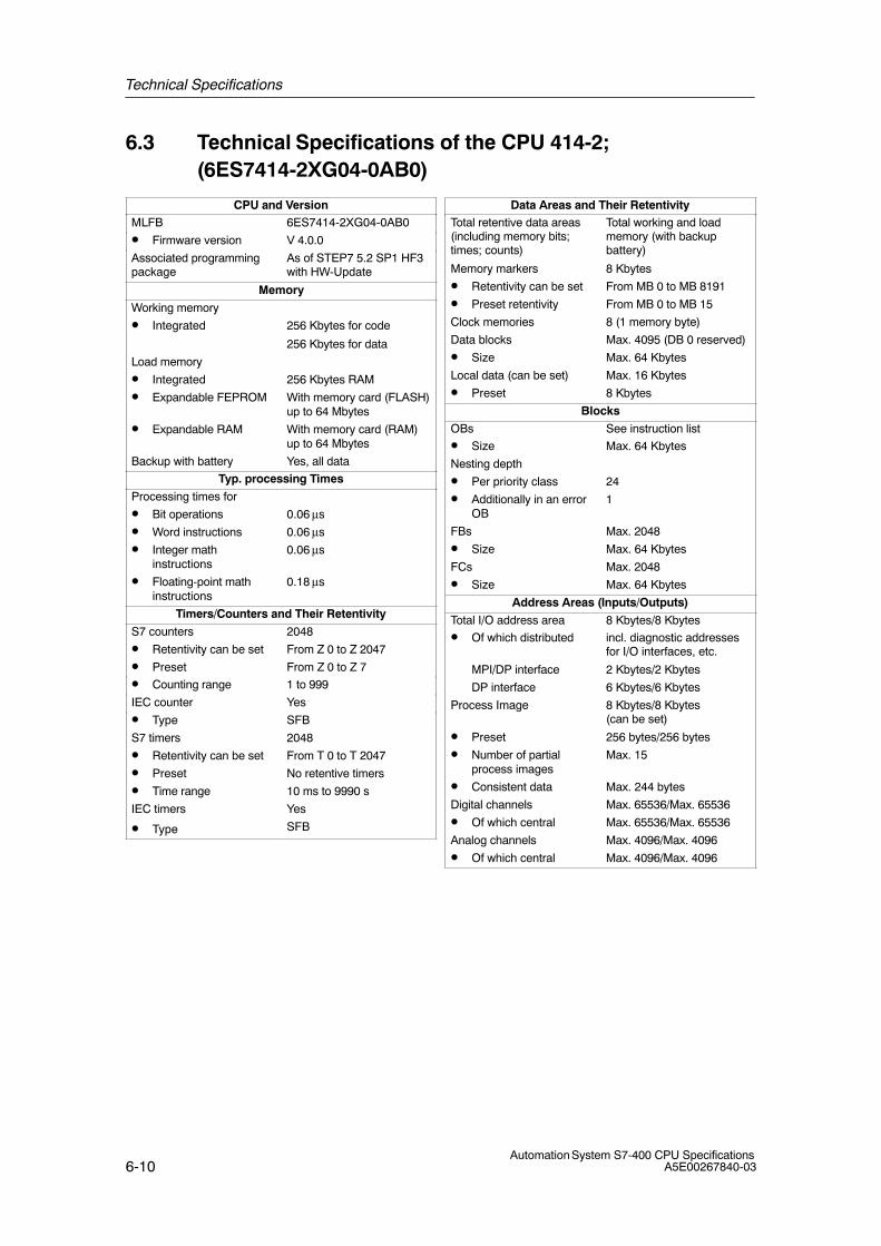
Technical Specifications
6-10Automation System S7-400 CPU Specifications
A5E00267840-03
6.3 Technical Specifications of the CPU 414-2; (6ES7414-2XG04-0AB0)
CPU and VersionMLFB 6ES7414-2XG04-0AB0
• Firmware version V 4.0.0
Associated programmingpackage
As of STEP7 5.2 SP1 HF3with HW-Update
Memory
Working memory
• Integrated 256 Kbytes for code
256 Kbytes for data
Load memory
• Integrated 256 Kbytes RAM
• Expandable FEPROM With memory card (FLASH)up to 64 Mbytes
• Expandable RAM With memory card (RAM)up to 64 Mbytes
Backup with battery Yes, all data
Typ. processing Times
Processing times for
• Bit operations 0.06 μs
• Word instructions 0.06 μs
• Integer mathinstructions
0.06 μs
• Floating-point mathinstructions
0.18 μs
Timers/Counters and Their Retentivity
S7 counters 2048
• Retentivity can be set From Z 0 to Z 2047
• Preset From Z 0 to Z 7
• Counting range 1 to 999
IEC counter Yes
• Type SFB
S7 timers 2048
• Retentivity can be set From T 0 to T 2047
• Preset No retentive timers
• Time range 10 ms to 9990 s
IEC timers Yes
• Type SFB
Data Areas and Their RetentivityTotal retentive data areas(including memory bits;times; counts)
Total working and loadmemory (with backupbattery)
Memory markers 8 Kbytes
• Retentivity can be set From MB 0 to MB 8191
• Preset retentivity From MB 0 to MB 15
Clock memories 8 (1 memory byte)
Data blocks Max. 4095 (DB 0 reserved)
• Size Max. 64 Kbytes
Local data (can be set) Max. 16 Kbytes
• Preset 8 Kbytes
Blocks
OBs See instruction list
• Size Max. 64 Kbytes
Nesting depth
• Per priority class 24
• Additionally in an errorOB
1
FBs Max. 2048
• Size Max. 64 Kbytes
FCs Max. 2048
• Size Max. 64 Kbytes
Address Areas (Inputs/Outputs)
Total I/O address area 8 Kbytes/8 Kbytes
• Of which distributed incl. diagnostic addressesfor I/O interfaces, etc.
MPI/DP interface 2 Kbytes/2 Kbytes
DP interface 6 Kbytes/6 Kbytes
Process Image 8 Kbytes/8 Kbytes (can be set)
• Preset 256 bytes/256 bytes
• Number of partialprocess images
Max. 15
• Consistent data Max. 244 bytes
Digital channels Max. 65536/Max. 65536
• Of which central Max. 65536/Max. 65536
Analog channels Max. 4096/Max. 4096
• Of which central Max. 4096/Max. 4096
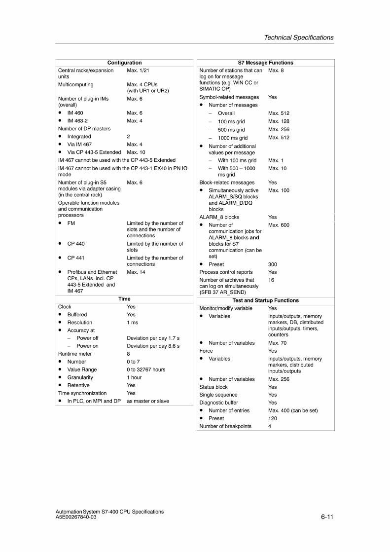
Technical Specifications
6-11Automation System S7-400 CPU SpecificationsA5E00267840-03
ConfigurationCentral racks/expansionunits
Max. 1/21
Multicomputing Max. 4 CPUs (with UR1 or UR2)
Number of plug-in IMs(overall)
Max. 6
• IM 460 Max. 6
• IM 463-2 Max. 4
Number of DP masters
• Integrated 2
• Via IM 467 Max. 4
• Via CP 443-5 Extended Max. 10
IM 467 cannot be used with the CP 443-5 Extended
IM 467 cannot be used with the CP 443-1 EX40 in PN IOmode
Number of plug-in S5modules via adapter casing(in the central rack)
Max. 6
Operable function modulesand communicationprocessors
• FM Limited by the number ofslots and the number ofconnections
• CP 440 Limited by the number ofslots
• CP 441 Limited by the number ofconnections
• Profibus and EthernetCPs, LANs incl. CP443-5 Extended andIM 467
Max. 14
Time
Clock Yes
• Buffered Yes
• Resolution 1 ms
• Accuracy at
– Power off Deviation per day 1.7 s
– Power on Deviation per day 8.6 s
Runtime meter 8
• Number 0 to 7
• Value Range 0 to 32767 hours
• Granularity 1 hour
• Retentive Yes
Time synchronization Yes
• In PLC, on MPI and DP as master or slave
S7 Message FunctionsNumber of stations that canlog on for messagefunctions (e.g. WIN CC orSIMATIC OP)
Max. 8
Symbol-related messages Yes
• Number of messages
– Overall
– 100 ms grid
– 500 ms grid
– 1000 ms grid
Max. 512
Max. 128
Max. 256
Max. 512
• Number of additionalvalues per message
– With 100 ms grid Max. 1
– With 500 – 1000ms grid
Max. 10
Block-related messages Yes
• Simultaneously activeALARM_S/SQ blocksand ALARM_D/DQblocks
Max. 100
ALARM_8 blocks Yes
• Number ofcommunication jobs forALARM_8 blocks andblocks for S7communication (can beset)
Max. 600
• Preset 300
Process control reports Yes
Number of archives thatcan log on simultaneously(SFB 37 AR_SEND)
16
Test and Startup Functions
Monitor/modify variable Yes
• Variables Inputs/outputs, memorymarkers, DB, distributedinputs/outputs, timers,counters
• Number of variables Max. 70
Force Yes
• Variables Inputs/outputs, memorymarkers, distributedinputs/outputs
• Number of variables Max. 256
Status block Yes
Single sequence Yes
Diagnostic buffer Yes
• Number of entries Max. 400 (can be set)
• Preset 120
Number of breakpoints 4
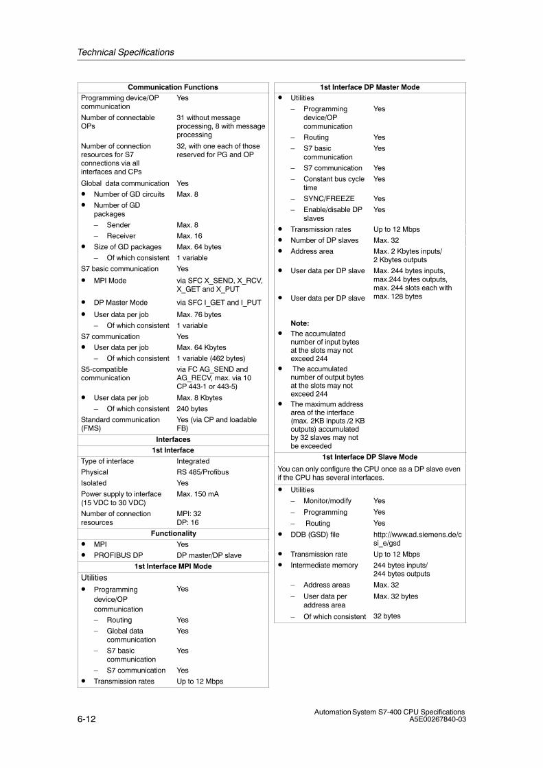
Technical Specifications
6-12Automation System S7-400 CPU Specifications
A5E00267840-03
Communication FunctionsProgramming device/OPcommunication
Yes
Number of connectableOPs
31 without messageprocessing, 8 with messageprocessing
Number of connectionresources for S7connections via allinterfaces and CPs
32, with one each of thosereserved for PG and OP
Global data communication Yes
• Number of GD circuits Max. 8
• Number of GDpackages
– Sender Max. 8
– Receiver Max. 16
• Size of GD packages Max. 64 bytes
– Of which consistent 1 variable
S7 basic communication Yes
• MPI Mode via SFC X_SEND, X_RCV,X_GET and X_PUT
• DP Master Mode via SFC I_GET and I_PUT
• User data per job Max. 76 bytes
– Of which consistent 1 variable
S7 communication Yes
• User data per job Max. 64 Kbytes
– Of which consistent 1 variable (462 bytes)
S5-compatiblecommunication
via FC AG_SEND andAG_RECV, max. via 10CP 443-1 or 443-5)
• User data per job Max. 8 Kbytes
– Of which consistent 240 bytes
Standard communication(FMS)
Yes (via CP and loadableFB)
Interfaces1st Interface
Type of interface Integrated
Physical RS 485/Profibus
Isolated Yes
Power supply to interface(15 VDC to 30 VDC)
Max. 150 mA
Number of connectionresources
MPI: 32DP: 16
Functionality
• MPI Yes
• PROFIBUS DP DP master/DP slave
1st Interface MPI Mode
Utilities• Programming
device/OPcommunication
Yes
– Routing Yes
– Global datacommunication
Yes
– S7 basiccommunication
Yes
– S7 communication Yes
• Transmission rates Up to 12 Mbps
1st Interface DP Master Mode• Utilities
– Programmingdevice/OPcommunication
Yes
– Routing Yes
– S7 basiccommunication
Yes
– S7 communication Yes
– Constant bus cycletime
Yes
– SYNC/FREEZE Yes
– Enable/disable DPslaves
Yes
• Transmission rates Up to 12 Mbps
• Number of DP slaves Max. 32
• Address area Max. 2 Kbytes inputs/2 Kbytes outputs
• User data per DP slave
• User data per DP slave
Note:• The accumulated
number of input bytesat the slots may notexceed 244
• The accumulatednumber of output bytesat the slots may notexceed 244
• The maximum addressarea of the interface(max. 2KB inputs /2 KBoutputs) accumulatedby 32 slaves may notbe exceeded
Max. 244 bytes inputs,max.244 bytes outputs,max. 244 slots each withmax. 128 bytes
1st Interface DP Slave Mode
You can only configure the CPU once as a DP slave evenif the CPU has several interfaces.
• Utilities
– Monitor/modify
– Programming
– Routing
Yes
Yes
Yes
• DDB (GSD) file http://www.ad.siemens.de/csi_e/gsd
• Transmission rate Up to 12 Mbps
• Intermediate memory 244 bytes inputs/244 bytes outputs
– Address areas
– User data peraddress area
– Of which consistent
Max. 32
Max. 32 bytes
32 bytes
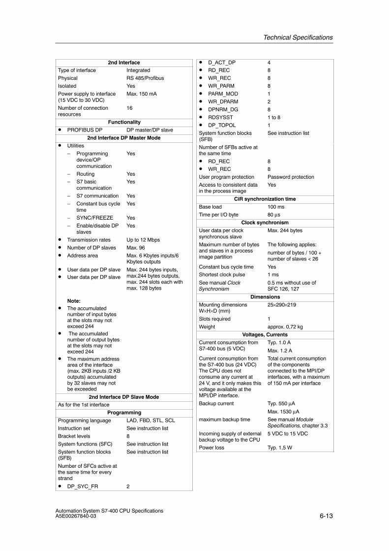
Technical Specifications
6-13Automation System S7-400 CPU SpecificationsA5E00267840-03
2nd InterfaceType of interface Integrated
Physical RS 485/Profibus
Isolated Yes
Power supply to interface(15 VDC to 30 VDC)
Max. 150 mA
Number of connectionresources
16
Functionality
• PROFIBUS DP DP master/DP slave
2nd Interface DP Master Mode
• Utilities
– Programmingdevice/OPcommunication
Yes
– Routing Yes
– S7 basiccommunication
Yes
– S7 communication Yes
– Constant bus cycletime
Yes
– SYNC/FREEZE Yes
– Enable/disable DPslaves
Yes
• Transmission rates Up to 12 Mbps
• Number of DP slaves Max. 96
• Address area Max. 6 Kbytes inputs/6Kbytes outputs
• User data per DP slave• User data per DP slave
Note:• The accumulated
number of input bytesat the slots may notexceed 244
• The accumulatednumber of output bytesat the slots may notexceed 244
• The maximum addressarea of the interface(max. 2KB inputs /2 KBoutputs) accumulatedby 32 slaves may notbe exceeded
Max. 244 bytes inputs,max.244 bytes outputs,max. 244 slots each withmax. 128 bytes
2nd Interface DP Slave ModeAs for the 1st interface
Programming
Programming language LAD, FBD, STL, SCL
Instruction set See instruction list
Bracket levels 8
System functions (SFC) See instruction list
System function blocks(SFB)
See instruction list
Number of SFCs active atthe same time for everystrand
• DP_SYC_FR 2
• D_ACT_DP 4
• RD_REC 8
• WR_REC 8
• WR_PARM 8
• PARM_MOD 1
• WR_DPARM 2
• DPNRM_DG 8
• RDSYSST 1 to 8
• DP_TOPOL 1
System function blocks(SFB)
See instruction list
Number of SFBs active atthe same time
• RD_REC 8
• WR_REC 8
User program protection Password protection
Access to consistent datain the process image
Yes
CiR synchronization time
Base load 100 ms
Time per I/O byte 80 μs
Clock synchronism
User data per clocksynchronous slave
Max. 244 bytes
Maximum number of bytesand slaves in a processimage partition
The following applies:
number of bytes / 100 +number of slaves < 26
Constant bus cycle time Yes
Shortest clock pulse
See manual ClockSynchronism
1 ms
0.5 ms without use ofSFC 126, 127
Dimensions
Mounting dimensionsW×H×D (mm)
25×290×219
Slots required 1
Weight approx. 0,72 kg
Voltages, Currents
Current consumption fromS7-400 bus (5 VDC)
Typ. 1.0 A
Max. 1.2 A
Current consumption fromthe S7-400 bus (24 VDC)The CPU does notconsume any current at24 V, and it only makes thisvoltage available at theMPI/DP interface.
Total current consumptionof the componentsconnected to the MPI/DPinterfaces, with a maximumof 150 mA per interface
Backup current Typ. 550 μA
Max. 1530 μA
maximum backup time See manual ModuleSpecifications, chapter 3.3
Incoming supply of externalbackup voltage to the CPU
5 VDC to 15 VDC
Power loss Typ. 1,5 W

Technical Specifications
6-14Automation System S7-400 CPU Specifications
A5E00267840-03
6.4 Technical Specifications of the CPU 414-3; (6ES7414-3XJ04-0AB0)
CPU and VersionMLFB 6ES7414-3XJ04-0AB0
• Firmware version V 4.0.0
Associated programmingpackage
As of STEP 7 5.2 SP1 HF3with HW-Update
Memory
Working memory
• Integrated 700 Kbytes for code
700 Kbytes for data
Load memory
• Integrated 256 Kbytes RAM
• Expandable FEPROM With memory card (FLASH)up to 64 Mbytes
• Expandable RAM With memory card (RAM)up to 64 Mbytes
Backup with battery Yes, all data
Typ. Processing Times
Processing times for
• Bit operations 0.06 μs
• Word instructions 0.06 μs
• Integer mathinstructions
0.06 μs
• Floating-point mathinstructions
0.18 μs
Timers/Counters and Their Retentivity
S7 counters 2048
• Retentivity can be set From Z 0 to Z 2047
• Preset From Z 0 to Z 7
• Counting range 1 to 999
IEC counter Yes
• Type SFB
S7 timers 2048
• Retentivity can be set From T 0 to T 2047
• Preset No retentive timers
• Time range 10 ms to 9990 s
IEC timers Yes
• Type SFB
Data Areas and Their RetentivityTotal retentive data areas(including memory bits;times; counts)
Total working and loadmemory (with backupbattery)
Memory markers 8 Kbytes
• Retentivity can be set From MB 0 to MB 8191
• Preset retentivity From MB 0 to MB 15
Clock memories 8 (1 memory byte)
Data blocks Max. 4095 (DB 0 reserved)
• Size Max. 64 Kbytes
Local data (can be set) Max. 16 Kbytes
• Preset 8 Kbytes
Blocks
OBs See instruction list
• Size Max. 64 Kbytes
Nesting depth
• Per priority class 24
• Additionally in an errorOB
1
FBs Max. 2048
• Size Max. 64 Kbytes
FCs Max. 2048
• Size Max. 64 Kbytes
Address Areas (Inputs/Outputs)
Total I/O address area 8 Kbytes/8 Kbytes
• Of which distributed incl. diagnostics addressesfor I/O interfaces, etc.
MPI/DP interface 2 Kbytes/2 Kbytes
DP interface 6 Kbytes/6 Kbytes
Process Image 8 Kbytes/8 Kbytes (can be set)
• Preset 256 bytes/256 bytes
• Number of partialprocess images
Max. 15
• Consistent data Max. 244 bytes
Digital channels Max. 65536/Max. 65536
• Of which central Max. 65536/Max. 65536
Analog channels Max. 4096/Max. 4096
• Of which central Max. 4096/Max. 4096

Technical Specifications
6-15Automation System S7-400 CPU SpecificationsA5E00267840-03
ConfigurationCentral racks/expansionunits
Max. 1/21
Multicomputing Max. 4 CPUs (with UR1 or UR2)
Number of plug-in IMs(overall)
Max. 6
• IM 460 Max. 6
• IM 463-2 Max. 4
Number of DP masters
• Integrated 2
• Via IF 964-DP 1
• Via IM 467 Max. 4
• Via CP 443-5 Extended Max. 10
IM 467 cannot be used with the CP 443-5 ExtendedIM 467 cannot be used with the CP 443-1 EX40 in PN IOmode
Number of plug-in S5modules via adapter casing(in the central rack)
Max. 6
Operable function modulesand communicationprocessors
• FM Limited by the number ofslots and the number ofconnections
• CP 440 Limited by the number ofslots
• CP 441 Limited by the number ofconnections
• Profibus and EthernetCPs incl. CP 443-5Extended and IM 467
Max. 14
Time
Clock Yes
• Buffered Yes
• Resolution 1 ms
• Accuracy at
– Power off Deviation per day 1.7 s
– Power on Deviation per day 8.6 s
Runtime meter 8
• Number 0 to 7
• Value Range 0 to 32767 hours
• Granularity 1 hour
• Retentive Yes
Time synchronization Yes
• In PLC, on MPI, DPand IF 964-DP
as master or slave
S7 Message FunctionsNumber of stations that canlog on for messagefunctions (e.g. WIN CC orSIMATIC OP)
Max. 8
Symbol-related messages Yes
• Number of messages
– Overall
– 100 ms grid
– 500 ms grid
– 1000 ms grid
Max. 512Max. 128Max. 256Max. 512
• Number of additionalvalues per message
– With 100 ms grid Max. 1
– With 500 to 1000ms grid
Max. 10
Block-related messages Yes
• Simultaneously activeALARM-S/SQ blocksand ALARM-D/DQblocks
Max. 100
ALARM-8 blocks Yes
• Number ofcommunication jobs forALARM-8 blocks andblocks for S7communication (can beset)
Max. 600
• Preset 300
Process control reports Yes
Number of archives thatcan log on simultaneously(SFB 37 AR_SEND)
16
Test and Startup Functions
Monitor/modify variable Yes
• Variables Inputs/outputs, memorymarkers, DB, distributedinputs/outputs, timers,counters
• Number of variables Max. 70
Force Yes
• Variables Inputs/outputs, memorymarkers, distributedinputs/outputs
• Number of variables Max. 256
Status block Yes
Single sequence Yes
Diagnostic buffer Yes
• Number of entries Max. 3200 (can be set)
• Preset 120
Number of breakpoints 4
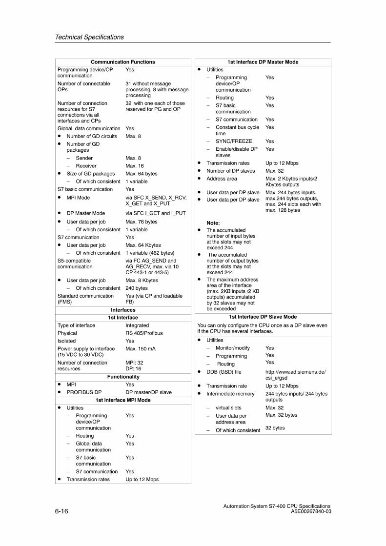
Technical Specifications
6-16Automation System S7-400 CPU Specifications
A5E00267840-03
Communication FunctionsProgramming device/OPcommunication
Yes
Number of connectableOPs
31 without messageprocessing, 8 with messageprocessing
Number of connectionresources for S7connections via allinterfaces and CPs
32, with one each of thosereserved for PG and OP
Global data communication Yes
• Number of GD circuits Max. 8
• Number of GDpackages
– Sender Max. 8
– Receiver Max. 16
• Size of GD packages Max. 64 bytes
– Of which consistent 1 variable
S7 basic communication Yes
• MPI Mode via SFC X_SEND, X_RCV,X_GET and X_PUT
• DP Master Mode via SFC I_GET and I_PUT
• User data per job Max. 76 bytes
– Of which consistent 1 variable
S7 communication Yes
• User data per job Max. 64 Kbytes
– Of which consistent 1 variable (462 bytes)
S5-compatiblecommunication
via FC AG_SEND andAG_RECV, max. via 10CP 443-1 or 443-5)
• User data per job Max. 8 Kbytes
– Of which consistent 240 bytes
Standard communication(FMS)
Yes (via CP and loadableFB)
Interfaces1st Interface
Type of interface Integrated
Physical RS 485/Profibus
Isolated Yes
Power supply to interface(15 VDC to 30 VDC)
Max. 150 mA
Number of connectionresources
MPI: 32DP: 16
Functionality
• MPI Yes
• PROFIBUS DP DP master/DP slave
1st Interface MPI Mode
• Utilities
– Programmingdevice/OPcommunication
Yes
– Routing Yes
– Global datacommunication
Yes
– S7 basiccommunication
Yes
– S7 communication Yes
• Transmission rates Up to 12 Mbps
1st Interface DP Master Mode• Utilities
– Programmingdevice/OPcommunication
Yes
– Routing Yes
– S7 basiccommunication
Yes
– S7 communication Yes
– Constant bus cycletime
Yes
– SYNC/FREEZE Yes
– Enable/disable DPslaves
Yes
• Transmission rates Up to 12 Mbps
• Number of DP slaves Max. 32
• Address area Max. 2 Kbytes inputs/2Kbytes outputs
• User data per DP slave• User data per DP slave
Note:• The accumulated
number of input bytesat the slots may notexceed 244
• The accumulatednumber of output bytesat the slots may notexceed 244
• The maximum addressarea of the interface(max. 2KB inputs /2 KBoutputs) accumulatedby 32 slaves may notbe exceeded
Max. 244 bytes inputs,max.244 bytes outputs,max. 244 slots each withmax. 128 bytes
1st Interface DP Slave Mode
You can only configure the CPU once as a DP slave evenif the CPU has several interfaces.
• Utilities
– Monitor/modify
– Programming
– Routing
YesYesYes
• DDB (GSD) file http://www.ad.siemens.de/csi_e/gsd
• Transmission rate Up to 12 Mbps
• Intermediate memory 244 bytes inputs/ 244 bytesoutputs
– virtual slots
– User data peraddress area
– Of which consistent
Max. 32Max. 32 bytes
32 bytes
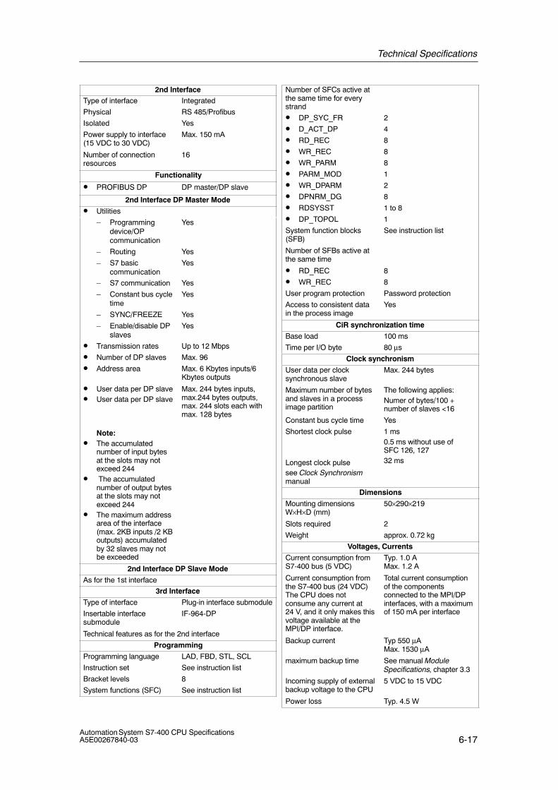
Technical Specifications
6-17Automation System S7-400 CPU SpecificationsA5E00267840-03
2nd InterfaceType of interface Integrated
Physical RS 485/Profibus
Isolated Yes
Power supply to interface(15 VDC to 30 VDC)
Max. 150 mA
Number of connectionresources
16
Functionality
• PROFIBUS DP DP master/DP slave
2nd Interface DP Master Mode
• Utilities
– Programmingdevice/OPcommunication
Yes
– Routing Yes
– S7 basiccommunication
Yes
– S7 communication Yes
– Constant bus cycletime
Yes
– SYNC/FREEZE Yes
– Enable/disable DPslaves
Yes
• Transmission rates Up to 12 Mbps
• Number of DP slaves Max. 96
• Address area Max. 6 Kbytes inputs/6Kbytes outputs
• User data per DP slave• User data per DP slave
Note:• The accumulated
number of input bytesat the slots may notexceed 244
• The accumulatednumber of output bytesat the slots may notexceed 244
• The maximum addressarea of the interface(max. 2KB inputs /2 KBoutputs) accumulatedby 32 slaves may notbe exceeded
Max. 244 bytes inputs,max.244 bytes outputs,max. 244 slots each withmax. 128 bytes
2nd Interface DP Slave Mode
As for the 1st interface
3rd Interface
Type of interface Plug-in interface submodule
Insertable interfacesubmodule
IF-964-DP
Technical features as for the 2nd interface
Programming
Programming language LAD, FBD, STL, SCL
Instruction set See instruction list
Bracket levels 8
System functions (SFC) See instruction list
Number of SFCs active atthe same time for everystrand
• DP_SYC_FR 2
• D_ACT_DP 4
• RD_REC 8
• WR_REC 8
• WR_PARM 8
• PARM_MOD 1
• WR_DPARM 2
• DPNRM_DG 8
• RDSYSST 1 to 8
• DP_TOPOL 1
System function blocks(SFB)
See instruction list
Number of SFBs active atthe same time
• RD_REC 8
• WR_REC 8
User program protection Password protection
Access to consistent datain the process image
Yes
CiR synchronization time
Base load 100 ms
Time per I/O byte 80 μs
Clock synchronism
User data per clocksynchronous slave
Max. 244 bytes
Maximum number of bytesand slaves in a processimage partition
The following applies:Numer of bytes/100 +number of slaves <16
Constant bus cycle time Yes
Shortest clock pulse
Longest clock pulsesee Clock Synchronismmanual
1 ms0.5 ms without use ofSFC 126, 12732 ms
Dimensions
Mounting dimensionsW×H×D (mm)
50×290×219
Slots required 2
Weight approx. 0.72 kg
Voltages, Currents
Current consumption fromS7-400 bus (5 VDC)
Typ. 1.0 A Max. 1.2 A
Current consumption fromthe S7-400 bus (24 VDC)The CPU does notconsume any current at24 V, and it only makes thisvoltage available at theMPI/DP interface.
Total current consumptionof the componentsconnected to the MPI/DPinterfaces, with a maximumof 150 mA per interface
Backup current Typ 550 μAMax. 1530 μA
maximum backup time See manual ModuleSpecifications, chapter 3.3
Incoming supply of externalbackup voltage to the CPU
5 VDC to 15 VDC
Power loss Typ. 4.5 W
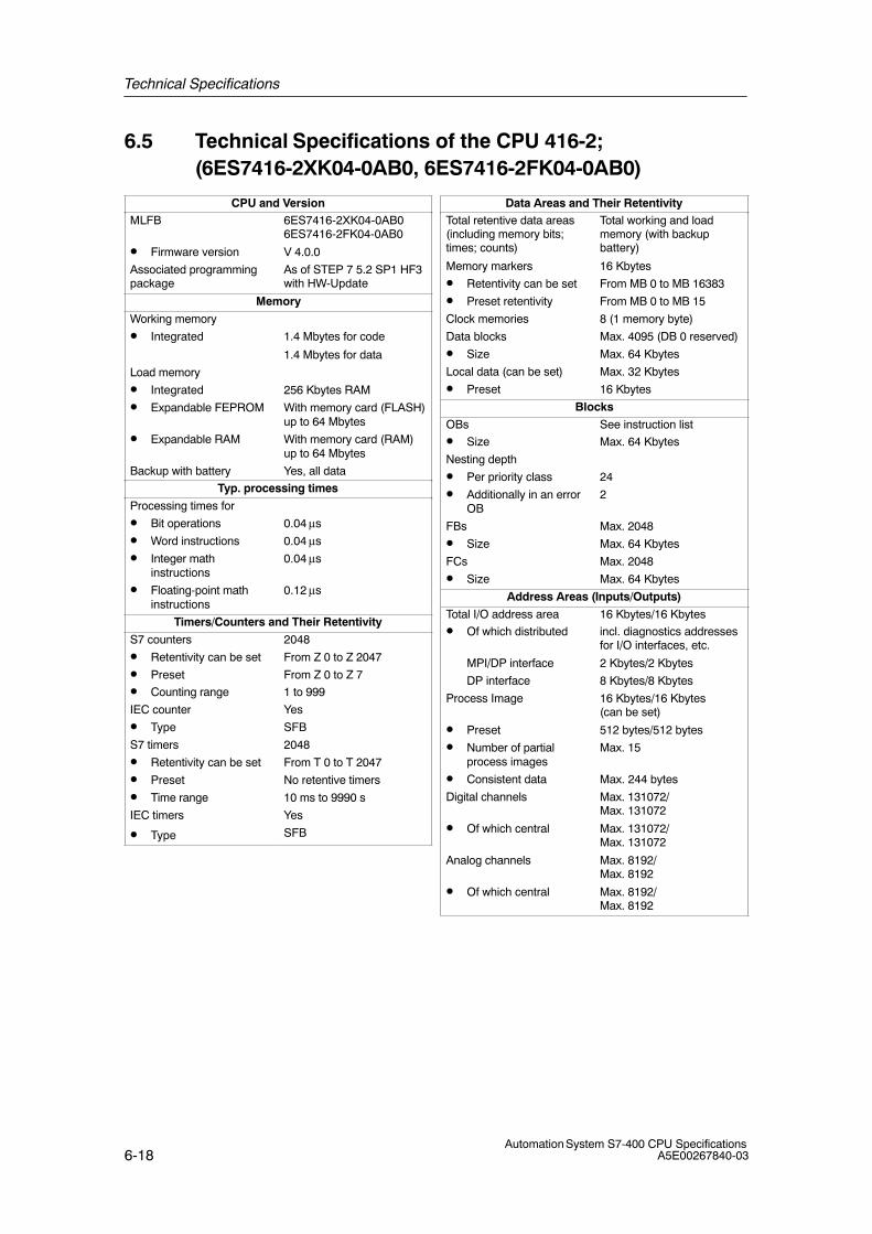
Technical Specifications
6-18Automation System S7-400 CPU Specifications
A5E00267840-03
6.5 Technical Specifications of the CPU 416-2; (6ES7416-2XK04-0AB0, 6ES7416-2FK04-0AB0)
CPU and VersionMLFB 6ES7416-2XK04-0AB0
6ES7416-2FK04-0AB0
• Firmware version V 4.0.0
Associated programmingpackage
As of STEP 7 5.2 SP1 HF3with HW-Update
Memory
Working memory
• Integrated 1.4 Mbytes for code
1.4 Mbytes for data
Load memory
• Integrated 256 Kbytes RAM
• Expandable FEPROM With memory card (FLASH)up to 64 Mbytes
• Expandable RAM With memory card (RAM)up to 64 Mbytes
Backup with battery Yes, all data
Typ. processing times
Processing times for
• Bit operations 0.04 μs
• Word instructions 0.04 μs
• Integer mathinstructions
0.04 μs
• Floating-point mathinstructions
0.12 μs
Timers/Counters and Their Retentivity
S7 counters 2048
• Retentivity can be set From Z 0 to Z 2047
• Preset From Z 0 to Z 7
• Counting range 1 to 999
IEC counter Yes
• Type SFB
S7 timers 2048
• Retentivity can be set From T 0 to T 2047
• Preset No retentive timers
• Time range 10 ms to 9990 s
IEC timers Yes
• Type SFB
Data Areas and Their RetentivityTotal retentive data areas(including memory bits;times; counts)
Total working and loadmemory (with backupbattery)
Memory markers 16 Kbytes
• Retentivity can be set From MB 0 to MB 16383
• Preset retentivity From MB 0 to MB 15
Clock memories 8 (1 memory byte)
Data blocks Max. 4095 (DB 0 reserved)
• Size Max. 64 Kbytes
Local data (can be set) Max. 32 Kbytes
• Preset 16 Kbytes
Blocks
OBs See instruction list
• Size Max. 64 Kbytes
Nesting depth
• Per priority class 24
• Additionally in an errorOB
2
FBs Max. 2048
• Size Max. 64 Kbytes
FCs Max. 2048
• Size Max. 64 Kbytes
Address Areas (Inputs/Outputs)
Total I/O address area 16 Kbytes/16 Kbytes
• Of which distributed incl. diagnostics addressesfor I/O interfaces, etc.
MPI/DP interface 2 Kbytes/2 Kbytes
DP interface 8 Kbytes/8 Kbytes
Process Image 16 Kbytes/16 Kbytes (can be set)
• Preset 512 bytes/512 bytes
• Number of partialprocess images
Max. 15
• Consistent data Max. 244 bytes
Digital channels Max. 131072/Max. 131072
• Of which central Max. 131072/Max. 131072
Analog channels Max. 8192/Max. 8192
• Of which central Max. 8192/Max. 8192
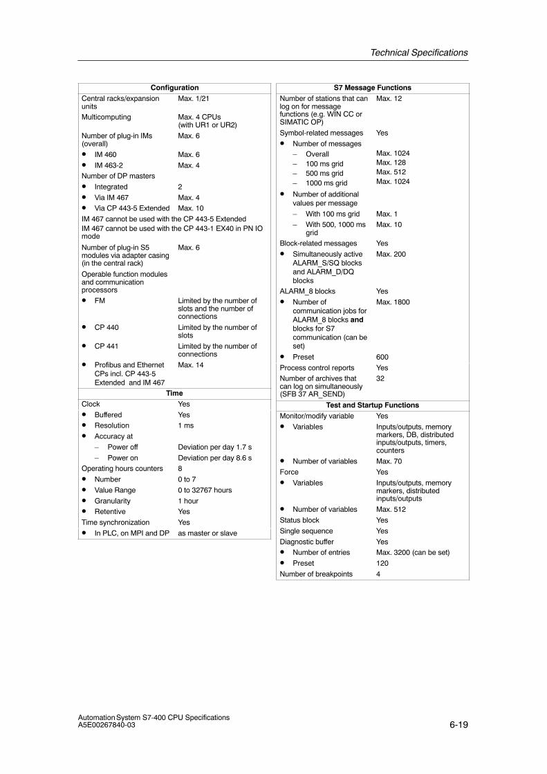
Technical Specifications
6-19Automation System S7-400 CPU SpecificationsA5E00267840-03
ConfigurationCentral racks/expansionunits
Max. 1/21
Multicomputing Max. 4 CPUs (with UR1 or UR2)
Number of plug-in IMs(overall)
Max. 6
• IM 460 Max. 6
• IM 463-2 Max. 4Number of DP masters
• Integrated 2
• Via IM 467 Max. 4• Via CP 443-5 Extended Max. 10
IM 467 cannot be used with the CP 443-5 ExtendedIM 467 cannot be used with the CP 443-1 EX40 in PN IOmode
Number of plug-in S5modules via adapter casing(in the central rack)
Max. 6
Operable function modulesand communicationprocessors
• FM Limited by the number ofslots and the number ofconnections
• CP 440 Limited by the number ofslots
• CP 441 Limited by the number ofconnections
• Profibus and EthernetCPs incl. CP 443-5Extended and IM 467
Max. 14
TimeClock Yes
• Buffered Yes• Resolution 1 ms
• Accuracy at
– Power off Deviation per day 1.7 s
– Power on Deviation per day 8.6 sOperating hours counters 8
• Number 0 to 7
• Value Range 0 to 32767 hours
• Granularity 1 hour• Retentive Yes
Time synchronization Yes
• In PLC, on MPI and DP as master or slave
S7 Message FunctionsNumber of stations that canlog on for messagefunctions (e.g. WIN CC orSIMATIC OP)
Max. 12
Symbol-related messages Yes
• Number of messages– Overall– 100 ms grid– 500 ms grid– 1000 ms grid
Max. 1024Max. 128Max. 512Max. 1024
• Number of additionalvalues per message
– With 100 ms grid Max. 1– With 500, 1000 ms
gridMax. 10
Block-related messages Yes
• Simultaneously activeALARM_S/SQ blocksand ALARM_D/DQblocks
Max. 200
ALARM_8 blocks Yes
• Number ofcommunication jobs forALARM_8 blocks andblocks for S7communication (can beset)
Max. 1800
• Preset 600
Process control reports YesNumber of archives thatcan log on simultaneously(SFB 37 AR_SEND)
32
Test and Startup FunctionsMonitor/modify variable Yes
• Variables Inputs/outputs, memorymarkers, DB, distributedinputs/outputs, timers,counters
• Number of variables Max. 70
Force Yes
• Variables Inputs/outputs, memorymarkers, distributedinputs/outputs
• Number of variables Max. 512
Status block Yes
Single sequence Yes
Diagnostic buffer Yes• Number of entries Max. 3200 (can be set)
• Preset 120
Number of breakpoints 4
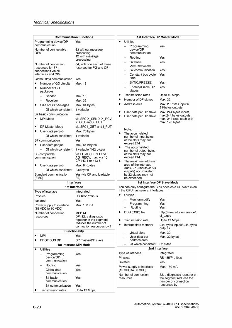
Technical Specifications
6-20Automation System S7-400 CPU Specifications
A5E00267840-03
Communication FunctionsProgramming device/OPcommunication
Yes
Number of connectableOPs
63 without messageprocessing,12 with messageprocessing
Number of connectionresources for S7connections via allinterfaces and CPs
64, with one each of thosereserved for PG and OP
Global data communication Yes
• Number of GD circuits Max. 16• Number of GD
packages
– Sender Max. 16
– Receiver Max. 32• Size of GD packages Max. 64 bytes
– Of which consistent 1 variable
S7 basic communication Yes
• MPI Mode via SFC X_SEND, X_RCV,X_GET and X_PUT
• DP Master Mode via SFC I_GET and I_PUT
• User data per job Max. 76 bytes
– Of which consistent 1 variable
S7 communication Yes• User data per job Max. 64 Kbytes
– Of which consistent 1 variable (462 bytes)
S5-compatiblecommunication
via FC AG_SEND andAG_RECV, max. via 10CP 443-1 or 443-5)
• User data per job Max. 8 Kbytes
– Of which consistent 240 bytes
Standard communication(FMS)
Yes (via CP and loadableFB)
Interfaces1st Interface
Type of interface Integrated
Physical RS 485/Profibus
Isolated YesPower supply to interface(15 VDC to 30 VDC)
Max. 150 mA
Number of connectionresources
MPI: 44DP: 32, a diagnosticrepeater in the segmentreduces the number ofconnection resources by 1
Functionality• MPI Yes
• PROFIBUS DP DP master/DP slave
1st Interface MPI Mode• Utilities
– Programmingdevice/OPcommunication
Yes
– Routing Yes
– Global datacommunication
Yes
– S7 basiccommunication
Yes
– S7 communication Yes
• Transmission rates Up to 12 Mbps
1st Interface DP Master Mode• Utilities
– Programmingdevice/OPcommunication
Yes
– Routing Yes
– S7 basiccommunication
Yes
– S7 communication Yes– Constant bus cycle
timeYes
– SYNC/FREEZE Yes
– Enable/disable DPslaves
Yes
• Transmission rates Up to 12 Mbps
• Number of DP slaves Max. 32
• Address area Max. 2 Kbytes inputs/ 2 Kbytes outputs
• User data per DP slave• User data per DP slave
Note:• The accumulated
number of input bytesat the slots may notexceed 244
• The accumulatednumber of output bytesat the slots may notexceed 244
• The maximum addressarea of the interface(max. 2KB inputs /2 KBoutputs) accumulatedby 32 slaves may notbe exceeded
Max. 244 bytes inputs,max.244 bytes outputs,max. 244 slots each withmax. 128 bytes
1st Interface DP Slave ModeYou can only configure the CPU once as a DP slave evenif the CPU has several interfaces.
• Utilities
– Monitor/modify– Programming– Routing
YesYesYes
• DDB (GSD) file http://www.ad.siemens.de/csi_e/gsd
• Transmission rate Up to 12 Mbps
• Intermediate memory 244 bytes inputs/ 244 bytesoutputs
– virtual slots– User data per
address area– Of which consistent
Max. 32Max. 32 bytes
32 bytes2nd Interface
Type of interface Integrated
Physical RS 485/ProfibusIsolated Yes
Power supply to interface(15 VDC to 30 VDC)
Max. 150 mA
Number of connectionresources
32, a diagnostic repeater onthe segment reduces thenumber of connectionresources by 1
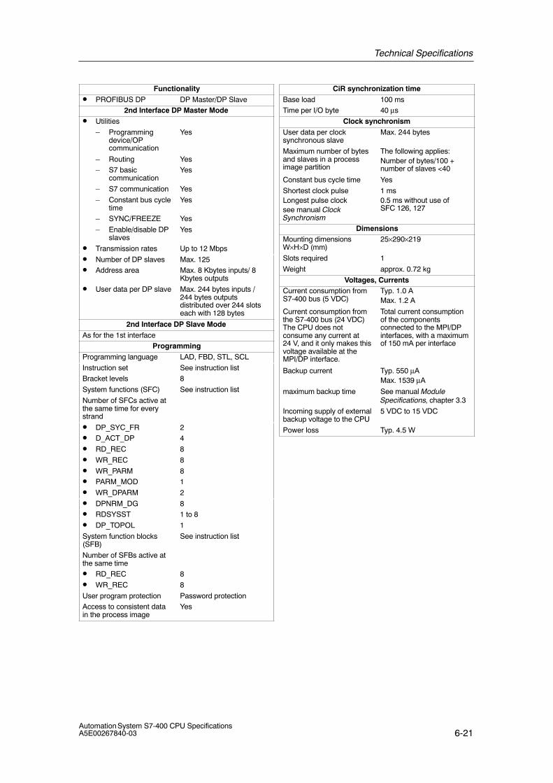
Technical Specifications
6-21Automation System S7-400 CPU SpecificationsA5E00267840-03
Functionality• PROFIBUS DP DP Master/DP Slave
2nd Interface DP Master Mode• Utilities
– Programmingdevice/OPcommunication
Yes
– Routing Yes– S7 basic
communicationYes
– S7 communication Yes
– Constant bus cycletime
Yes
– SYNC/FREEZE Yes
– Enable/disable DPslaves
Yes
• Transmission rates Up to 12 Mbps
• Number of DP slaves Max. 125• Address area Max. 8 Kbytes inputs/ 8
Kbytes outputs
• User data per DP slave Max. 244 bytes inputs /244 bytes outputsdistributed over 244 slotseach with 128 bytes
2nd Interface DP Slave ModeAs for the 1st interface
ProgrammingProgramming language LAD, FBD, STL, SCL
Instruction set See instruction listBracket levels 8
System functions (SFC) See instruction list
Number of SFCs active atthe same time for everystrand
• DP_SYC_FR 2• D_ACT_DP 4
• RD_REC 8
• WR_REC 8
• WR_PARM 8• PARM_MOD 1
• WR_DPARM 2
• DPNRM_DG 8• RDSYSST 1 to 8
• DP_TOPOL 1
System function blocks(SFB)
See instruction list
Number of SFBs active atthe same time• RD_REC 8
• WR_REC 8
User program protection Password protectionAccess to consistent datain the process image
Yes
CiR synchronization timeBase load 100 msTime per I/O byte 40 μs
Clock synchronismUser data per clocksynchronous slave
Max. 244 bytes
Maximum number of bytesand slaves in a processimage partition
The following applies:Number of bytes/100 +number of slaves <40
Constant bus cycle time Yes
Shortest clock pulseLongest pulse clocksee manual ClockSynchronism
1 ms0.5 ms without use ofSFC 126, 127
DimensionsMounting dimensionsW×H×D (mm)
25×290×219
Slots required 1
Weight approx. 0.72 kg
Voltages, CurrentsCurrent consumption fromS7-400 bus (5 VDC)
Typ. 1.0 AMax. 1.2 A
Current consumption fromthe S7-400 bus (24 VDC)The CPU does notconsume any current at24 V, and it only makes thisvoltage available at theMPI/DP interface.
Total current consumptionof the componentsconnected to the MPI/DPinterfaces, with a maximumof 150 mA per interface
Backup current Typ. 550 μAMax. 1539 μA
maximum backup time See manual ModuleSpecifications, chapter 3.3
Incoming supply of externalbackup voltage to the CPU
5 VDC to 15 VDC
Power loss Typ. 4.5 W
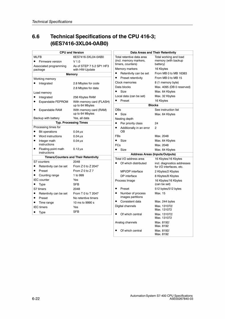
Technical Specifications
6-22Automation System S7-400 CPU Specifications
A5E00267840-03
6.6 Technical Specifications of the CPU 416-3; (6ES7416-3XL04-0AB0)
CPU and VersionMLFB 6ES7416-3XL04-0AB0
• Firmware version V 1.0
Associated programmingpackage
As of STEP 7 5.2 SP1 HF3with HW-Update
Memory
Working memory
• Integrated 2.8 Mbytes for code
2.8 Mbytes for data
Load memory
• Integrated 256 Kbytes RAM
• Expandable FEPROM With memory card (FLASH)up to 64 Mbytes
• Expandable RAM With memory card (RAM)up to 64 Mbytes
Backup with battery Yes, all data
Typ. Processing Times
Processing times for
• Bit operations 0.04 μs
• Word instructions 0.04 μs
• Integer mathinstructions
0.04 μs
• Floating-point mathinstructions
0.12 μs
Timers/Counters and Their Retentivity
S7 counters 2048
• Retentivity can be set From Z 0 to Z 2047
• Preset From Z 0 to Z 7
• Counting range 1 to 999
IEC counter Yes
• Type SFB
S7 timers 2048
• Retentivity can be set From T 0 to T 2047
• Preset No retentive timers
• Time range 10 ms to 9990 s
IEC timers Yes
• Type SFB
Data Areas and Their RetentivityTotal retentive data area(incl. memory markers,timers, counters)
Total working and loadmemory (with backupbattery)
Memory markers 16 Kbytes
• Retentivity can be set From MB 0 to MB 16383
• Preset retentivity From MB 0 to MB 15
Clock memories 8 (1 memory byte)
Data blocks Max. 4095 (DB 0 reserved)
• Size Max. 64 Kbytes
Local data (can be set) Max. 32 Kbytes
• Preset 16 Kbytes
Blocks
OBs See instruction list
• Size Max. 64 Kbytes
Nesting depth
• Per priority class 24
• Additionally in an errorOB
2
FBs Max. 2048
• Size Max. 64 Kbytes
FCs Max. 2048
• Size Max. 64 Kbytes
Address Areas (Inputs/Outputs)
Total I/O address area 16 Kbytes/16 Kbytes
• Of which distributed incl. diagnostics addressesfor I/O interfaces, etc.
MPI/DP interface 2 Kbytes/2 Kbytes
DP interface 8 Kbytes/8 Kbytes
Process Image 16 Kbytes/16 Kbytes (can be set)
• Preset 512 bytes/512 bytes
• Number of processimages partitions
Max. 15
• Consistent data Max. 244 bytes
Digital channels Max. 131072/Max. 131072
• Of which central Max. 131072/Max. 131072
Analog channels Max. 8192/Max. 8192
• Of which central Max. 8192/Max. 8192
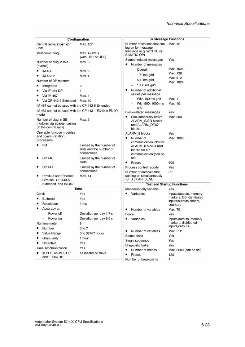
Technical Specifications
6-23Automation System S7-400 CPU SpecificationsA5E00267840-03
ConfigurationCentral racks/expansionunits
Max. 1/21
Multicomputing Max. 4 CPUs (with UR1 or UR2)
Number of plug-in IMs(overall)
Max. 6
• IM 460 Max. 6
• IM 463-2 Max. 4
Number of DP masters
• Integrated 2
• Via IF 964-DP 1
• Via IM 467 Max. 4
• Via CP 443-5 Extended Max. 10
IM 467 cannot be used with the CP 443-5 Extended
IM 467 cannot be used with the CP 443-1 EX40 in PN IOmode
Number of plug-in S5modules via adapter casing(in the central rack)
Max. 6
Operable function modulesand communicationprocessors
• FM Limited by the number ofslots and the number ofconnections
• CP 440 Limited by the number ofslots
• CP 441 Limited by the number ofconnections
• Profibus and EthernetCPs incl. CP 443-5Extended and IM 467
Max. 14
Time
Clock Yes
• Buffered Yes
• Resolution 1 ms
• Accuracy at
– Power off Deviation per day 1.7 s
– Power on Deviation per day 8.6 s
Runtime meter 8
• Number 0 to 7
• Value Range 0 to 32767 hours
• Granularity 1 hour
• Retentive Yes
Time synchronization Yes
• In PLC, on MPI, DPand IF 964 DP
as master or slave
S7 Message FunctionsNumber of stations that canlog on for messagefunctions (e.g. WIN CC orSIMATIC OP)
Max. 12
Symbol-related messages Yes• Number of messages
– Overall
– 100 ms grid
– 500 ms grid
– 1000 ms grid
Max. 1024Max. 128Max. 512Max. 1024
• Number of additionalvalues per message– With 100 ms grid Max. 1– With 500, 1000 ms
gridMax. 10
Block-related messages Yes• Simultaneously active
ALARM_S/SQ blocksand ALARM_D/DQblocks
Max. 200
ALARM_8 blocks Yes• Number of
communication jobs forALARM_8 blocks andblocks for S7communication (can beset)
Max. 1800
• Preset 600Process control reports YesNumber of archives thatcan log on simultaneously(SFB 37 AR_SEND)
32
Test and Startup FunctionsMonitor/modify variable Yes• Variables Inputs/outputs, memory
markers, DB, distributedinputs/outputs, timers,counters
• Number of variables Max. 70Force Yes• Variables Inputs/outputs, memory
markers, distributedinputs/outputs
• Number of variables Max. 512Status block YesSingle sequence YesDiagnostic buffer Yes• Number of entries Max. 3200 (can be set)• Preset 120Number of breakpoints 4
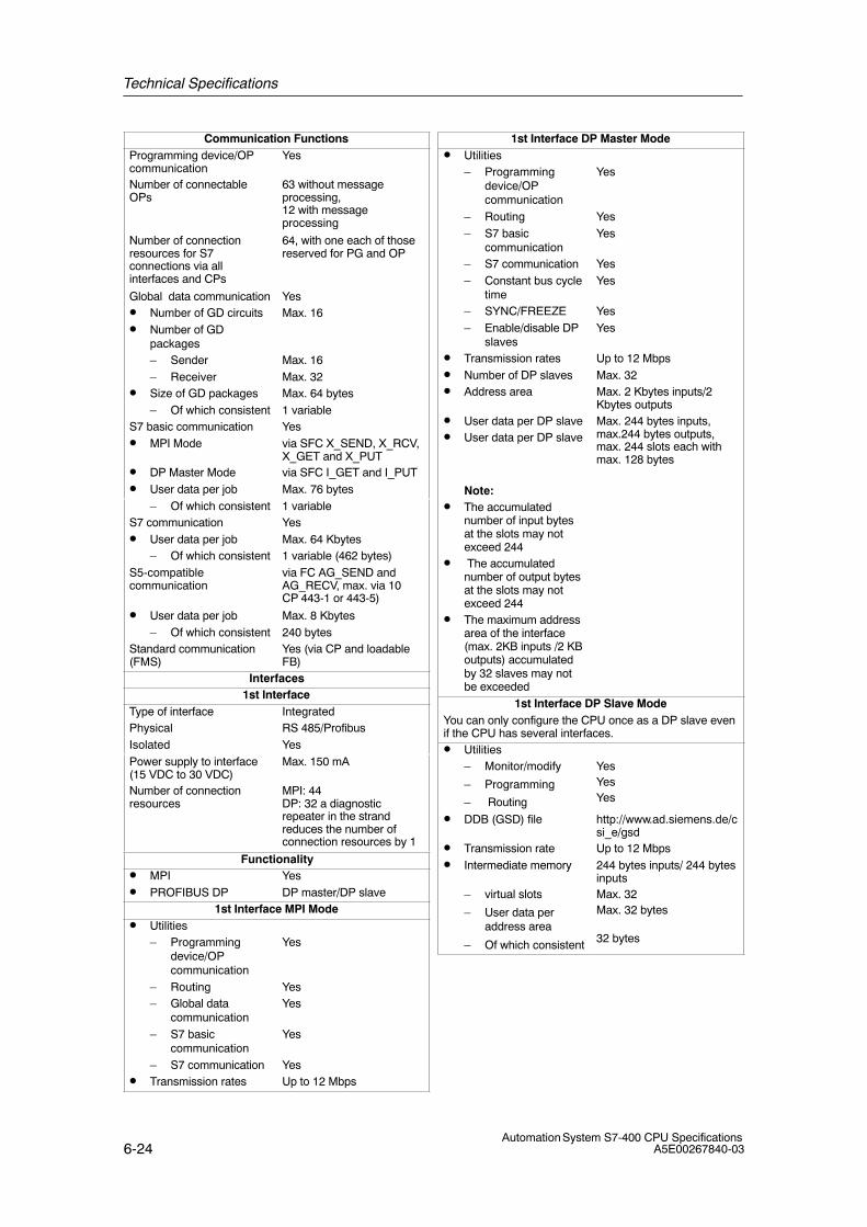
Technical Specifications
6-24Automation System S7-400 CPU Specifications
A5E00267840-03
Communication FunctionsProgramming device/OPcommunication
Yes
Number of connectableOPs
63 without messageprocessing,12 with messageprocessing
Number of connectionresources for S7connections via allinterfaces and CPs
64, with one each of thosereserved for PG and OP
Global data communication Yes• Number of GD circuits Max. 16• Number of GD
packages– Sender Max. 16– Receiver Max. 32
• Size of GD packages Max. 64 bytes– Of which consistent 1 variable
S7 basic communication Yes• MPI Mode via SFC X_SEND, X_RCV,
X_GET and X_PUT• DP Master Mode via SFC I_GET and I_PUT• User data per job Max. 76 bytes
– Of which consistent 1 variableS7 communication Yes• User data per job Max. 64 Kbytes
– Of which consistent 1 variable (462 bytes)S5-compatiblecommunication
via FC AG_SEND andAG_RECV, max. via 10CP 443-1 or 443-5)
• User data per job Max. 8 Kbytes– Of which consistent 240 bytes
Standard communication(FMS)
Yes (via CP and loadableFB)
Interfaces1st Interface
Type of interface IntegratedPhysical RS 485/ProfibusIsolated YesPower supply to interface(15 VDC to 30 VDC)
Max. 150 mA
Number of connectionresources
MPI: 44DP: 32 a diagnosticrepeater in the strandreduces the number ofconnection resources by 1
Functionality• MPI Yes• PROFIBUS DP DP master/DP slave
1st Interface MPI Mode• Utilities
– Programmingdevice/OPcommunication
Yes
– Routing Yes– Global data
communicationYes
– S7 basiccommunication
Yes
– S7 communication Yes• Transmission rates Up to 12 Mbps
1st Interface DP Master Mode• Utilities
– Programmingdevice/OPcommunication
Yes
– Routing Yes– S7 basic
communicationYes
– S7 communication Yes– Constant bus cycle
timeYes
– SYNC/FREEZE Yes– Enable/disable DP
slavesYes
• Transmission rates Up to 12 Mbps• Number of DP slaves Max. 32• Address area Max. 2 Kbytes inputs/2
Kbytes outputs• User data per DP slave• User data per DP slave
Note:• The accumulated
number of input bytesat the slots may notexceed 244
• The accumulatednumber of output bytesat the slots may notexceed 244
• The maximum addressarea of the interface(max. 2KB inputs /2 KBoutputs) accumulatedby 32 slaves may notbe exceeded
Max. 244 bytes inputs,max.244 bytes outputs,max. 244 slots each withmax. 128 bytes
1st Interface DP Slave ModeYou can only configure the CPU once as a DP slave evenif the CPU has several interfaces.• Utilities
– Monitor/modify
– Programming
– Routing
YesYesYes
• DDB (GSD) file http://www.ad.siemens.de/csi_e/gsd
• Transmission rate Up to 12 Mbps• Intermediate memory 244 bytes inputs/ 244 bytes
inputs– virtual slots
– User data peraddress area
– Of which consistent
Max. 32Max. 32 bytes
32 bytes
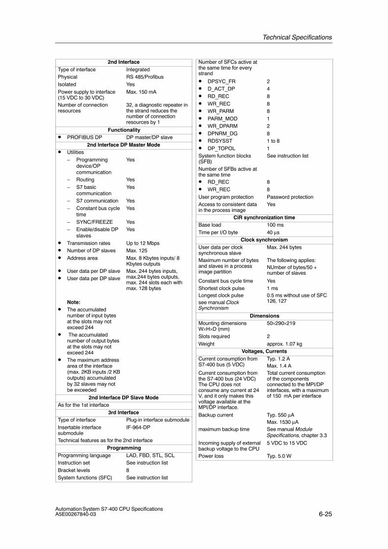
Technical Specifications
6-25Automation System S7-400 CPU SpecificationsA5E00267840-03
2nd InterfaceType of interface IntegratedPhysical RS 485/ProfibusIsolated YesPower supply to interface(15 VDC to 30 VDC)
Max. 150 mA
Number of connectionresources
32, a diagnostic repeater inthe strand reduces thenumber of connectionresources by 1
Functionality• PROFIBUS DP DP master/DP slave
2nd Interface DP Master Mode• Utilities
– Programmingdevice/OPcommunication
Yes
– Routing Yes– S7 basic
communicationYes
– S7 communication Yes– Constant bus cycle
timeYes
– SYNC/FREEZE Yes– Enable/disable DP
slavesYes
• Transmission rates Up to 12 Mbps• Number of DP slaves Max. 125• Address area Max. 8 Kbytes inputs/ 8
Kbytes outputs• User data per DP slave• User data per DP slave
Note:• The accumulated
number of input bytesat the slots may notexceed 244
• The accumulatednumber of output bytesat the slots may notexceed 244
• The maximum addressarea of the interface(max. 2KB inputs /2 KBoutputs) accumulatedby 32 slaves may notbe exceeded
Max. 244 bytes inputs,max.244 bytes outputs,max. 244 slots each withmax. 128 bytes
2nd Interface DP Slave ModeAs for the 1st interface
3rd InterfaceType of interface Plug-in interface submoduleInsertable interfacesubmodule
IF-964-DP
Technical features as for the 2nd interfaceProgramming
Programming language LAD, FBD, STL, SCLInstruction set See instruction listBracket levels 8System functions (SFC) See instruction list
Number of SFCs active atthe same time for everystrand
• DPSYC_FR 2• D_ACT_DP 4• RD_REC 8• WR_REC 8• WR_PARM 8• PARM_MOD 1• WR_DPARM 2• DPNRM_DG 8• RDSYSST 1 to 8• DP_TOPOL 1System function blocks(SFB)
See instruction list
Number of SFBs active atthe same time• RD_REC 8• WR_REC 8User program protection Password protectionAccess to consistent datain the process image
Yes
CiR synchronization timeBase load 100 msTime per I/O byte 40 μs
Clock synchronismUser data per clocksynchronous slave
Max. 244 bytes
Maximum number of bytesand slaves in a processimage partition
The following applies:NUmber of bytes/50 +number of slaves
Constant bus cycle time YesShortest clock pulseLongest clock pulsesee manual ClockSynchronism
1 ms0.5 ms without use of SFC126, 127
DimensionsMounting dimensionsW×H×D (mm)
50×290×219
Slots required 2Weight approx. 1.07 kg
Voltages, CurrentsCurrent consumption fromS7-400 bus (5 VDC)
Typ. 1.2 AMax. 1.4 A
Current consumption fromthe S7-400 bus (24 VDC)The CPU does notconsume any current at 24V, and it only makes thisvoltage available at theMPI/DP interface.
Total current consumptionof the componentsconnected to the MPI/DPinterfaces, with a maximumof 150 mA per interface
Backup current Typ. 550 μAMax. 1530 μA
maximum backup time See manual ModuleSpecifications, chapter 3.3
Incoming supply of externalbackup voltage to the CPU
5 VDC to 15 VDC
Power loss Typ. 5.0 W
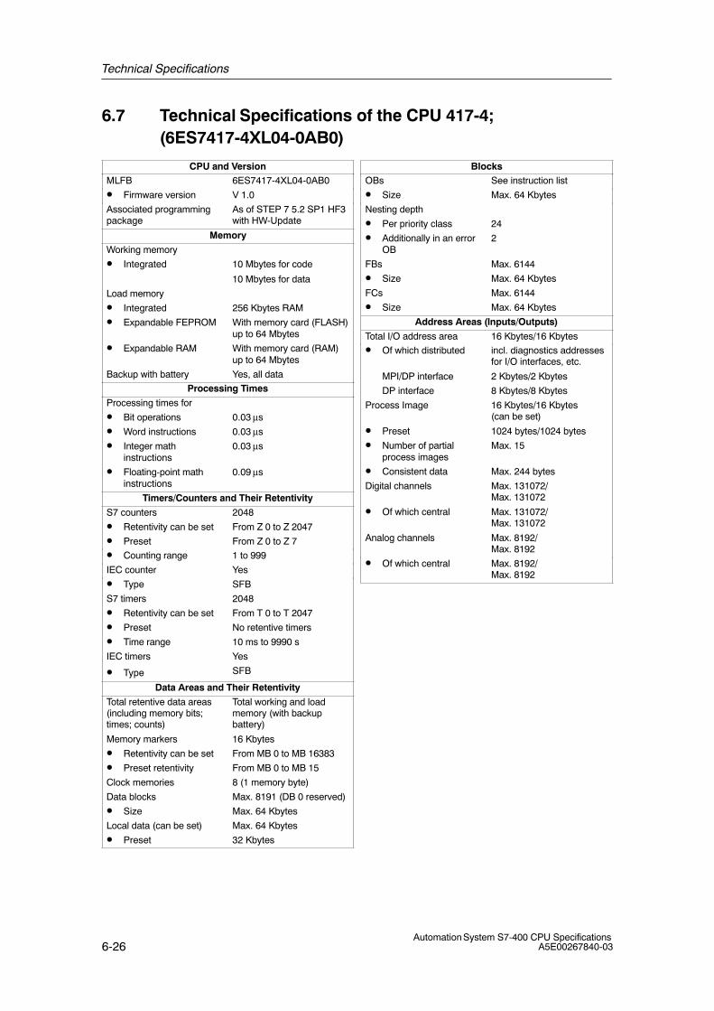
Technical Specifications
6-26Automation System S7-400 CPU Specifications
A5E00267840-03
6.7 Technical Specifications of the CPU 417-4; (6ES7417-4XL04-0AB0)
CPU and VersionMLFB 6ES7417-4XL04-0AB0
• Firmware version V 1.0
Associated programmingpackage
As of STEP 7 5.2 SP1 HF3with HW-Update
Memory
Working memory
• Integrated 10 Mbytes for code
10 Mbytes for data
Load memory
• Integrated 256 Kbytes RAM
• Expandable FEPROM With memory card (FLASH)up to 64 Mbytes
• Expandable RAM With memory card (RAM)up to 64 Mbytes
Backup with battery Yes, all data
Processing Times
Processing times for
• Bit operations 0.03 μs
• Word instructions 0.03 μs
• Integer mathinstructions
0.03 μs
• Floating-point mathinstructions
0.09 μs
Timers/Counters and Their Retentivity
S7 counters 2048
• Retentivity can be set From Z 0 to Z 2047
• Preset From Z 0 to Z 7
• Counting range 1 to 999
IEC counter Yes
• Type SFB
S7 timers 2048
• Retentivity can be set From T 0 to T 2047
• Preset No retentive timers
• Time range 10 ms to 9990 s
IEC timers Yes
• Type SFB
Data Areas and Their Retentivity
Total retentive data areas(including memory bits;times; counts)
Total working and loadmemory (with backupbattery)
Memory markers 16 Kbytes
• Retentivity can be set From MB 0 to MB 16383
• Preset retentivity From MB 0 to MB 15
Clock memories 8 (1 memory byte)
Data blocks Max. 8191 (DB 0 reserved)
• Size Max. 64 Kbytes
Local data (can be set) Max. 64 Kbytes
• Preset 32 Kbytes
BlocksOBs See instruction list
• Size Max. 64 Kbytes
Nesting depth
• Per priority class 24
• Additionally in an errorOB
2
FBs Max. 6144
• Size Max. 64 Kbytes
FCs Max. 6144
• Size Max. 64 Kbytes
Address Areas (Inputs/Outputs)
Total I/O address area 16 Kbytes/16 Kbytes
• Of which distributed incl. diagnostics addressesfor I/O interfaces, etc.
MPI/DP interface 2 Kbytes/2 Kbytes
DP interface 8 Kbytes/8 Kbytes
Process Image 16 Kbytes/16 Kbytes (can be set)
• Preset 1024 bytes/1024 bytes
• Number of partialprocess images
Max. 15
• Consistent data Max. 244 bytes
Digital channels Max. 131072/Max. 131072
• Of which central Max. 131072/Max. 131072
Analog channels Max. 8192/Max. 8192
• Of which central Max. 8192/Max. 8192

Technical Specifications
6-27Automation System S7-400 CPU SpecificationsA5E00267840-03
ConfigurationCentral racks/expansionunits
Max. 1/21
Multicomputing Max. 4 CPUs (with UR1 or UR2)
Number of plug-in IMs(overall)
Max. 6
• IM 460 Max. 6• IM 463-2 Max. 4Number of DP masters• Integrated 2• Via IF 964-DP 2• Via IM 467 Max. 4• Via CP 443-5 Extended Max. 10IM 467 cannot be used with the CP 443-5 ExtendedIM 467 cannot be used with the CP 443–1 EX40 in PN IOmode
Number of plug-in S5modules via adapter casing(in the central rack)
Max. 6
Operable function modulesand communicationprocessors
• FM Limited by the number ofslots and the number ofconnections
• CP 440 Limited by the number ofslots
• CP 441 Limited by the number ofconnections
• Profibus and EthernetCPs incl. CP 443-5Extended and IM 467
Max. 14
TimeClock Yes• Buffered Yes• Resolution 1 ms• Accuracy at
– Power off Deviation per day 1.7 s– Power on Deviation per day 8.6 s
Runtime meter 8• Number 0 to 7• Value Range 0 to 32767 hours• Granularity 1 hour• Retentive YesTime synchronization Yes• In PLC, on MPI, DP
and IF 964 DPas master or slave
S7 Message FunctionsNumber of stations that canlog on for messagefunctions (e.g. WIN CC orSIMATIC OP)
Max. 16
Symbol-related messages Yes• Number of messages
– Overall
– 100 ms grid
– 500 ms grid
– 1000 ms grid
Max. 1024Max. 128Max. 512Max. 1024
• Number of additionalvalues per message– With 100 ms grid Max. 1– With 500, 1000 ms
gridMax. 10
Block-related messages Yes• Simultaneously active
ALARM_S/SQ blocksand ALARM_D/DQblocks
Max. 200
ALARM_8 blocks Yes• Number of
communication jobs forALARM_8 blocks andblocks for S7communication (can beset)
Max. 10000
• Preset 1200Process control reports YesNumber of archives thatcan log on simultaneously(SFB 37 AR_SEND)
64
Test and Startup FunctionsMonitor/modify variable Yes• Variables Inputs/outputs, memory
markers, DB, distributedinputs/outputs, timers,counters
• Number of variables Max. 70Force Yes• Variables Inputs/outputs, memory
markers, distributedinputs/outputs
• Number of variables Max. 512Status block YesSingle sequence YesDiagnostic buffer Yes• Number of entries Max. 3200 (can be set)• Preset 120Number of breakpoints 4
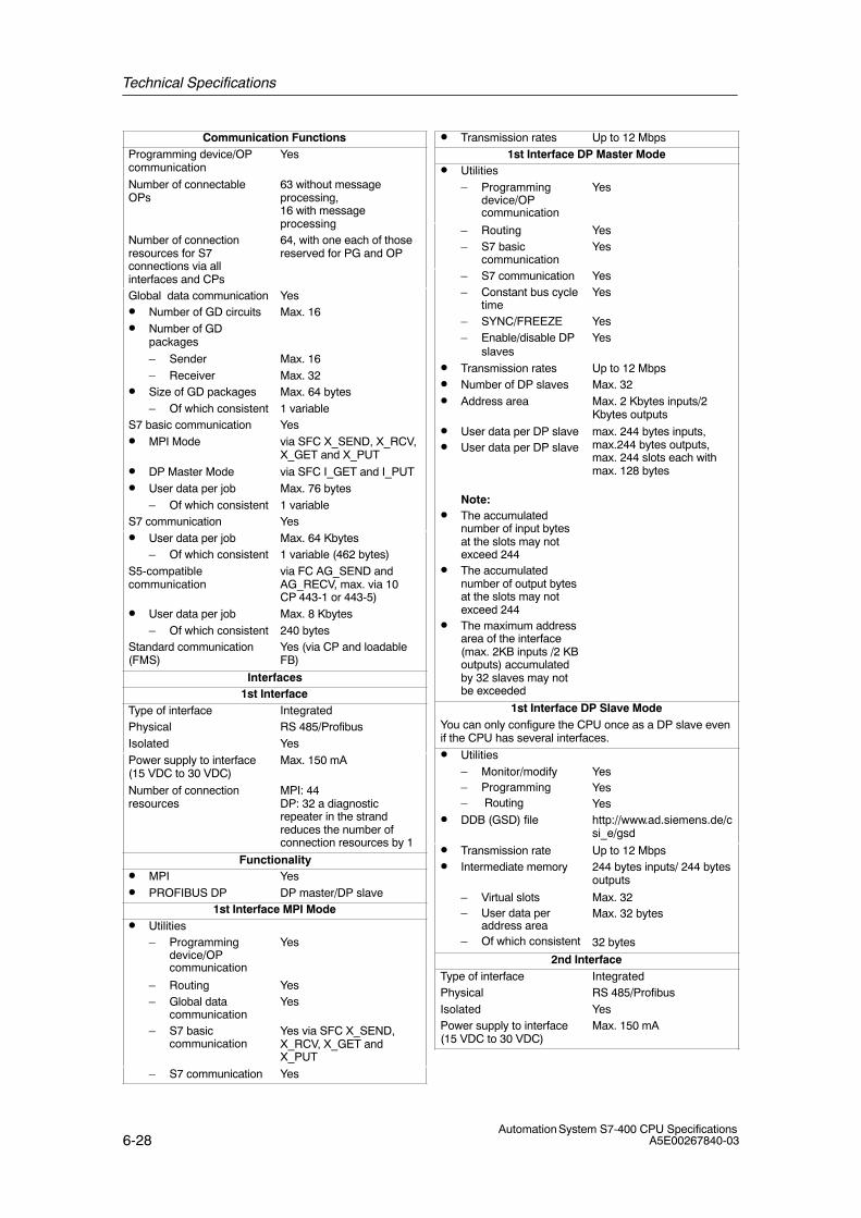
Technical Specifications
6-28Automation System S7-400 CPU Specifications
A5E00267840-03
Communication FunctionsProgramming device/OPcommunication
Yes
Number of connectableOPs
63 without messageprocessing,16 with messageprocessing
Number of connectionresources for S7connections via allinterfaces and CPs
64, with one each of thosereserved for PG and OP
Global data communication Yes• Number of GD circuits Max. 16• Number of GD
packages
– Sender Max. 16– Receiver Max. 32
• Size of GD packages Max. 64 bytes– Of which consistent 1 variable
S7 basic communication Yes• MPI Mode via SFC X_SEND, X_RCV,
X_GET and X_PUT
• DP Master Mode via SFC I_GET and I_PUT• User data per job Max. 76 bytes
– Of which consistent 1 variableS7 communication Yes• User data per job Max. 64 Kbytes
– Of which consistent 1 variable (462 bytes)S5-compatiblecommunication
via FC AG_SEND andAG_RECV, max. via 10CP 443-1 or 443-5)
• User data per job Max. 8 Kbytes– Of which consistent 240 bytes
Standard communication(FMS)
Yes (via CP and loadableFB)
Interfaces1st Interface
Type of interface IntegratedPhysical RS 485/ProfibusIsolated YesPower supply to interface(15 VDC to 30 VDC)
Max. 150 mA
Number of connectionresources
MPI: 44DP: 32 a diagnosticrepeater in the strandreduces the number ofconnection resources by 1
Functionality• MPI Yes• PROFIBUS DP DP master/DP slave
1st Interface MPI Mode• Utilities
– Programmingdevice/OPcommunication
Yes
– Routing Yes– Global data
communicationYes
– S7 basiccommunication
Yes via SFC X_SEND,X_RCV, X_GET andX_PUT
– S7 communication Yes
• Transmission rates Up to 12 Mbps1st Interface DP Master Mode
• Utilities– Programming
device/OPcommunication
Yes
– Routing Yes– S7 basic
communicationYes
– S7 communication Yes– Constant bus cycle
timeYes
– SYNC/FREEZE Yes– Enable/disable DP
slavesYes
• Transmission rates Up to 12 Mbps• Number of DP slaves Max. 32• Address area Max. 2 Kbytes inputs/2
Kbytes outputs
• User data per DP slave• User data per DP slave
Note:• The accumulated
number of input bytesat the slots may notexceed 244
• The accumulatednumber of output bytesat the slots may notexceed 244
• The maximum addressarea of the interface(max. 2KB inputs /2 KBoutputs) accumulatedby 32 slaves may notbe exceeded
max. 244 bytes inputs,max.244 bytes outputs,max. 244 slots each withmax. 128 bytes
1st Interface DP Slave ModeYou can only configure the CPU once as a DP slave evenif the CPU has several interfaces.
• Utilities– Monitor/modify– Programming– Routing
YesYesYes
• DDB (GSD) file http://www.ad.siemens.de/csi_e/gsd
• Transmission rate Up to 12 Mbps• Intermediate memory 244 bytes inputs/ 244 bytes
outputs
– Virtual slots– User data per
address area– Of which consistent
Max. 32Max. 32 bytes
32 bytes
2nd InterfaceType of interface IntegratedPhysical RS 485/ProfibusIsolated YesPower supply to interface(15 VDC to 30 VDC)
Max. 150 mA
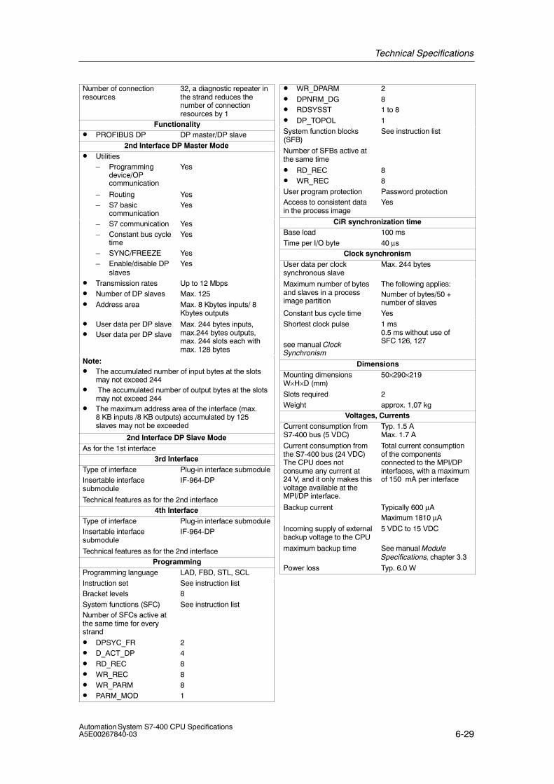
Technical Specifications
6-29Automation System S7-400 CPU SpecificationsA5E00267840-03
Number of connectionresources
32, a diagnostic repeater inthe strand reduces thenumber of connectionresources by 1
Functionality• PROFIBUS DP DP master/DP slave
2nd Interface DP Master Mode• Utilities
– Programmingdevice/OPcommunication
Yes
– Routing Yes– S7 basic
communicationYes
– S7 communication Yes– Constant bus cycle
timeYes
– SYNC/FREEZE Yes– Enable/disable DP
slavesYes
• Transmission rates Up to 12 Mbps• Number of DP slaves Max. 125• Address area Max. 8 Kbytes inputs/ 8
Kbytes outputs
• User data per DP slave• User data per DP slave
Max. 244 bytes inputs,max.244 bytes outputs,max. 244 slots each withmax. 128 bytes
Note:• The accumulated number of input bytes at the slots
may not exceed 244• The accumulated number of output bytes at the slots
may not exceed 244• The maximum address area of the interface (max.
8 KB inputs /8 KB outputs) accumulated by 125slaves may not be exceeded
2nd Interface DP Slave ModeAs for the 1st interface
3rd InterfaceType of interface Plug-in interface submoduleInsertable interfacesubmodule
IF-964-DP
Technical features as for the 2nd interface4th Interface
Type of interface Plug-in interface submoduleInsertable interfacesubmodule
IF-964-DP
Technical features as for the 2nd interfaceProgramming
Programming language LAD, FBD, STL, SCLInstruction set See instruction listBracket levels 8System functions (SFC) See instruction listNumber of SFCs active atthe same time for everystrand
• DPSYC_FR 2• D_ACT_DP 4• RD_REC 8• WR_REC 8• WR_PARM 8• PARM_MOD 1
• WR_DPARM 2• DPNRM_DG 8• RDSYSST 1 to 8• DP_TOPOL 1System function blocks(SFB)
See instruction list
Number of SFBs active atthe same time
• RD_REC 8• WR_REC 8User program protection Password protectionAccess to consistent datain the process image
Yes
CiR synchronization timeBase load 100 msTime per I/O byte 40 μs
Clock synchronismUser data per clocksynchronous slave
Max. 244 bytes
Maximum number of bytesand slaves in a processimage partition
The following applies:Number of bytes/50 +number of slaves
Constant bus cycle time YesShortest clock pulse
see manual ClockSynchronism
1 ms 0.5 ms without use ofSFC 126, 127
DimensionsMounting dimensionsW×H×D (mm)
50×290×219
Slots required 2Weight approx. 1,07 kg
Voltages, CurrentsCurrent consumption fromS7-400 bus (5 VDC)
Typ. 1.5 A Max. 1.7 A
Current consumption fromthe S7-400 bus (24 VDC)The CPU does notconsume any current at24 V, and it only makes thisvoltage available at theMPI/DP interface.
Total current consumptionof the componentsconnected to the MPI/DPinterfaces, with a maximumof 150 mA per interface
Backup current Typically 600 μAMaximum 1810 μA
Incoming supply of externalbackup voltage to the CPU
5 VDC to 15 VDC
maximum backup time See manual ModuleSpecifications, chapter 3.3
Power loss Typ. 6.0 W
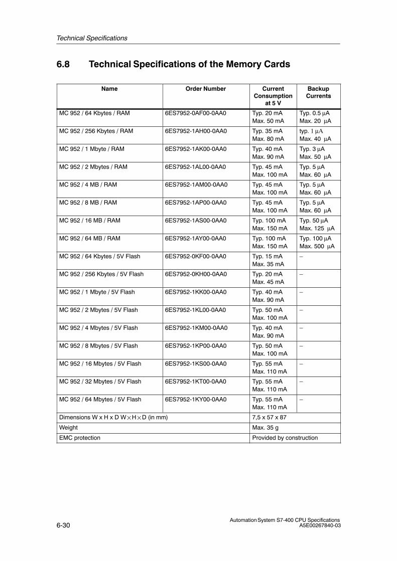
Technical Specifications
6-30Automation System S7-400 CPU Specifications
A5E00267840-03
6.8 Technical Specifications of the Memory Cards
Name Order Number CurrentConsumption
at 5 V
BackupCurrents
MC 952 / 64 Kbytes / RAM 6ES7952-0AF00-0AA0 Typ. 20 mAMax. 50 mA
Typ. 0.5 μAMax. 20 μA
MC 952 / 256 Kbytes / RAM 6ES7952-1AH00-0AA0 Typ. 35 mAMax. 80 mA
typ. � μ�Max. 40 μA
MC 952 / 1 Mbyte / RAM 6ES7952-1AK00-0AA0 Typ. 40 mAMax. 90 mA
Typ. 3 μAMax. 50 μA
MC 952 / 2 Mbytes / RAM 6ES7952-1AL00-0AA0 Typ. 45 mAMax. 100 mA
Typ. 5 μAMax. 60 μA
MC 952 / 4 MB / RAM 6ES7952-1AM00-0AA0 Typ. 45 mAMax. 100 mA
Typ. 5 μAMax. 60 μA
MC 952 / 8 MB / RAM 6ES7952-1AP00-0AA0 Typ. 45 mAMax. 100 mA
Typ. 5 μAMax. 60 μA
MC 952 / 16 MB / RAM 6ES7952-1AS00-0AA0 Typ. 100 mAMax. 150 mA
Typ. 50 μAMax. 125 μA
MC 952 / 64 MB / RAM 6ES7952-1AY00-0AA0 Typ. 100 mAMax. 150 mA
Typ. 100 μAMax. 500 μA
MC 952 / 64 Kbytes / 5V Flash 6ES7952-0KF00-0AA0 Typ. 15 mAMax. 35 mA
–
MC 952 / 256 Kbytes / 5V Flash 6ES7952-0KH00-0AA0 Typ. 20 mAMax. 45 mA
–
MC 952 / 1 Mbyte / 5V Flash 6ES7952-1KK00-0AA0 Typ. 40 mAMax. 90 mA
–
MC 952 / 2 Mbytes / 5V Flash 6ES7952-1KL00-0AA0 Typ. 50 mAMax. 100 mA
–
MC 952 / 4 Mbytes / 5V Flash 6ES7952-1KM00-0AA0 Typ. 40 mAMax. 90 mA
–
MC 952 / 8 Mbytes / 5V Flash 6ES7952-1KP00-0AA0 Typ. 50 mAMax. 100 mA
–
MC 952 / 16 Mbytes / 5V Flash 6ES7952-1KS00-0AA0 Typ. 55 mAMax. 110 mA
–
MC 952 / 32 Mbytes / 5V Flash 6ES7952-1KT00-0AA0 Typ. 55 mAMax. 110 mA
–
MC 952 / 64 Mbytes / 5V Flash 6ES7952-1KY00-0AA0 Typ. 55 mAMax. 110 mA
–
Dimensions W x H x D W�H�D (in mm) 7,5 x 57 x 87
Weight Max. 35 g
EMC protection Provided by construction
7-1Automation System S7-400 CPU SpecificationsA5E00267840-03
IF 964-DP Interface Submodule
Chapter Overview
Section You will Find Page
7.1 IF 964-DP Interface Submodule for S7-400 7-2
7
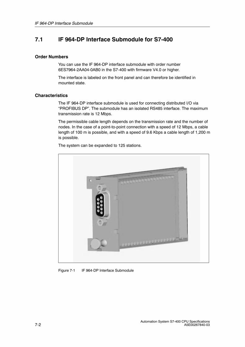
IF 964-DP Interface Submodule
7-2Automation System S7-400 CPU Specifications
A5E00267840-03
7.1 IF 964-DP Interface Submodule for S7-400
Order Numbers
You can use the IF 964-DP interface submodule with order number6ES7964-2AA04-0AB0 in the S7-400 with firmware V4.0 or higher.
The interface is labeled on the front panel and can therefore be identified inmounted state.
Characteristics
The IF 964-DP interface submodule is used for connecting distributed I/O via“PROFIBUS DP”. The submodule has an isolated RS485 interface. The maximumtransmission rate is 12 Mbps.
The permissible cable length depends on the transmission rate and the number ofnodes. In the case of a point-to-point connection with a speed of 12 Mbps, a cablelength of 100 m is possible, and with a speed of 9.6 Kbps a cable length of 1,200 mis possible.
The system can be expanded to 125 stations.
Figure 7-1 IF 964-DP Interface Submodule
IF 964-DP Interface Submodule
7-3Automation System S7-400 CPU SpecificationsA5E00267840-03
Note
Even in an S7-400 CPU you may remove or insert the IF 964-DP interfacesubmodule only if it is off circuit.
If you remove the interface submodule while the power supply is switched on, theCPU goes into DEFECTIVE mode.
Additional Information
You can find information on “PROFIBUS DP” in the following technical overviews ormanuals:
• DP master manuals, for example, S7-300 Programmable Controller or S7-400,Programmable Controllers for the PROFIBUS-DP interface
• Manuals on the DP slaves, for example, ET 200M Distributed I/O Device orET 200C Distributed I/O Device
• STEP 7 manuals
7.1.1 Pin Assignments
X1 Connector
There is a 9-pin sub D socket connector on the frontside of the submodule forplugging in the connecting cable. See Table 7-1 for the pin assignments.
Table 7-1 X1 Socket, IF 964-DP (9-Pin Sub D Connector)
Pin Signal Meaning Direction
1 –
2 M 24 24 V reference potential Output
3 LTG_B Line B Input/Output
4 RTSAS Request to send (AS) Output
5 M5ext Operational ground (isolated) Output
6 P5ext + 5 V (isolated), max. 90 mA(for supplying the bus terminator)
Output
7 P 24 V +24 V, max. 150 mA, non-isolated Output
8 LTG_A Line A Input
9 –
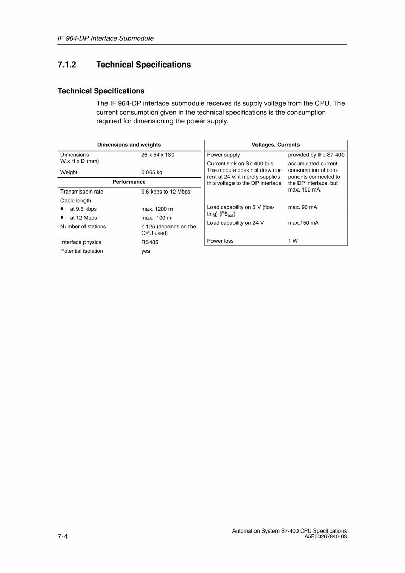
IF 964-DP Interface Submodule
7-4Automation System S7-400 CPU Specifications
A5E00267840-03
7.1.2 Technical Specifications
Technical Specifications
The IF 964-DP interface submodule receives its supply voltage from the CPU. Thecurrent consumption given in the technical specifications is the consumptionrequired for dimensioning the power supply.
Dimensions and weights
DimensionsW x H x D (mm)
26 x 54 x 130
Weight 0.065 kg
Performance
Transmissoin rate 9.6 kbps to 12 Mbps
Cable length
• at 9.6 kbps
• at 12 Mbps
max. 1200 m
max. 100 m
Number of stations ≤ 125 (depends on theCPU used)
Interface physics RS485
Potential isolation yes
Voltages, Currents
Power supply provided by the S7-400
Current sink on S7-400 busThe module does not draw cur-rent at 24 V, it merely suppliesthis voltage to the DP interface
accumulated currentconsumption of com-ponents connected tothe DP interface, butmax. 150 mA
Load capability on 5 V (floa-ting) (P5ext)
max. 90 mA
Load capability on 24 V max.150 mA
Power loss 1 W
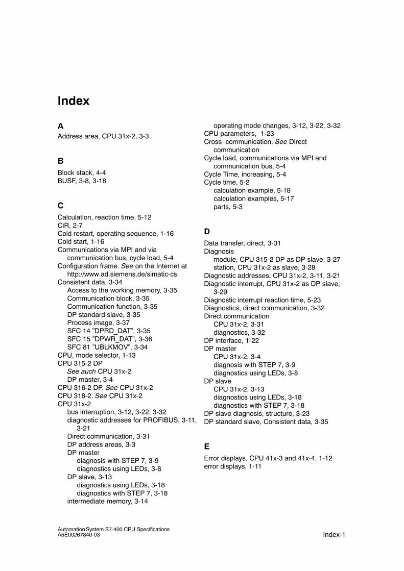
Index-1Automation System S7-400 CPU SpecificationsA5E00267840-03
Index
AAddress area, CPU 31x-2, 3-3
BBlock stack, 4-4BUSF, 3-8, 3-18
CCalculation, reaction time, 5-12CiR, 2-7Cold restart, operating sequence, 1-16Cold start, 1-16Communications via MPI and via
communication bus, cycle load, 5-4Configuration frame. See on the Internet at
http://www.ad.siemens.de/simatic-csConsistent data, 3-34
Access to the working memory, 3-35Communication block, 3-35Communication function, 3-35DP standard slave, 3-35Process image, 3-37SFC 14 ”DPRD_DAT”, 3-35SFC 15 ”DPWR_DAT”, 3-36SFC 81 ”UBLKMOV”, 3-34
CPU, mode selector, 1-13CPU 315-2 DP
See auch CPU 31x-2DP master, 3-4
CPU 316-2 DP. See CPU 31x-2CPU 318-2. See CPU 31x-2CPU 31x-2
bus interruption, 3-12, 3-22, 3-32diagnostic addresses for PROFIBUS, 3-11,
3-21Direct communication, 3-31DP address areas, 3-3DP master
diagnosis with STEP 7, 3-9diagnostics using LEDs, 3-8
DP slave, 3-13diagnostics using LEDs, 3-18diagnostics with STEP 7, 3-18
intermediate memory, 3-14
operating mode changes, 3-12, 3-22, 3-32CPU parameters, 1-23Cross–communication. See Direct
communicationCycle load, communications via MPI and
communication bus, 5-4Cycle Time, increasing, 5-4Cycle time, 5-2
calculation example, 5-18calculation examples, 5-17parts, 5-3
DData transfer, direct, 3-31Diagnosis
module, CPU 315-2 DP as DP slave, 3-27station, CPU 31x-2 as slave, 3-28
Diagnostic addresses, CPU 31x-2, 3-11, 3-21Diagnostic interrupt, CPU 31x-2 as DP slave,
3-29Diagnostic interrupt reaction time, 5-23Diagnostics, direct communication, 3-32Direct communication
CPU 31x-2, 3-31diagnostics, 3-32
DP interface, 1-22DP master
CPU 31x-2, 3-4diagnosis with STEP 7, 3-9diagnostics using LEDs, 3-8
DP slaveCPU 31x-2, 3-13diagnostics using LEDs, 3-18diagnostics with STEP 7, 3-18
DP slave diagnosis, structure, 3-23DP standard slave, Consistent data, 3-35
EError displays, CPU 41x-3 and 41x-4, 1-12error displays, 1-11
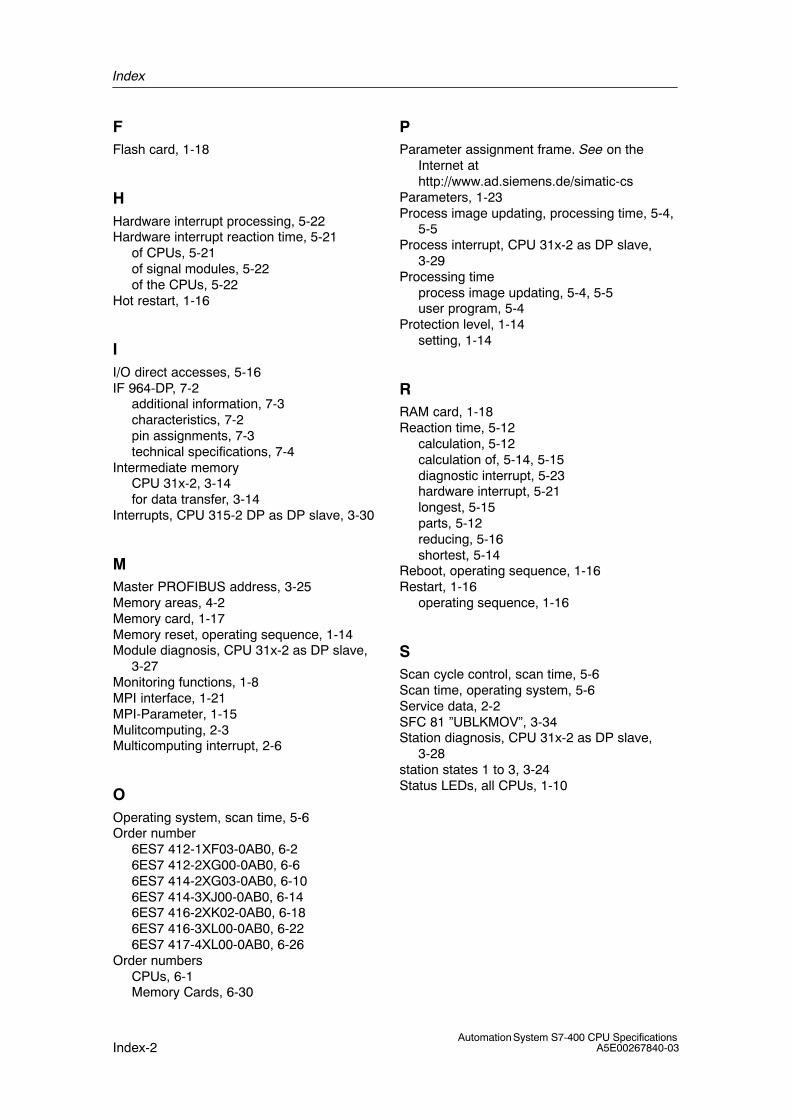
Index
Index-2Automation System S7-400 CPU Specifications
A5E00267840-03
FFlash card, 1-18
HHardware interrupt processing, 5-22Hardware interrupt reaction time, 5-21
of CPUs, 5-21of signal modules, 5-22of the CPUs, 5-22
Hot restart, 1-16
II/O direct accesses, 5-16IF 964-DP, 7-2
additional information, 7-3characteristics, 7-2pin assignments, 7-3technical specifications, 7-4
Intermediate memoryCPU 31x-2, 3-14for data transfer, 3-14
Interrupts, CPU 315-2 DP as DP slave, 3-30
MMaster PROFIBUS address, 3-25Memory areas, 4-2Memory card, 1-17Memory reset, operating sequence, 1-14Module diagnosis, CPU 31x-2 as DP slave,
3-27Monitoring functions, 1-8MPI interface, 1-21MPI-Parameter, 1-15Mulitcomputing, 2-3Multicomputing interrupt, 2-6
OOperating system, scan time, 5-6Order number
6ES7 412-1XF03-0AB0, 6-26ES7 412-2XG00-0AB0, 6-66ES7 414-2XG03-0AB0, 6-106ES7 414-3XJ00-0AB0, 6-146ES7 416-2XK02-0AB0, 6-186ES7 416-3XL00-0AB0, 6-226ES7 417-4XL00-0AB0, 6-26
Order numbersCPUs, 6-1Memory Cards, 6-30
PParameter assignment frame. See on the
Internet athttp://www.ad.siemens.de/simatic-cs
Parameters, 1-23Process image updating, processing time, 5-4,
5-5Process interrupt, CPU 31x-2 as DP slave,
3-29Processing time
process image updating, 5-4, 5-5user program, 5-4
Protection level, 1-14setting, 1-14
RRAM card, 1-18Reaction time, 5-12
calculation, 5-12calculation of, 5-14, 5-15diagnostic interrupt, 5-23hardware interrupt, 5-21longest, 5-15parts, 5-12reducing, 5-16shortest, 5-14
Reboot, operating sequence, 1-16Restart, 1-16
operating sequence, 1-16
SScan cycle control, scan time, 5-6Scan time, operating system, 5-6Service data, 2-2SFC 81 ”UBLKMOV”, 3-34Station diagnosis, CPU 31x-2 as DP slave,
3-28station states 1 to 3, 3-24Status LEDs, all CPUs, 1-10
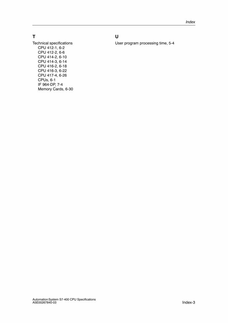
Index
Index-3Automation System S7-400 CPU SpecificationsA5E00267840-03
TTechnical specifications
CPU 412-1, 6-2CPU 412-2, 6-6CPU 414-2, 6-10CPU 414-3, 6-14CPU 416-2, 6-18CPU 416-3, 6-22CPU 417-4, 6-26CPUs, 6-1IF 964-DP, 7-4Memory Cards, 6-30
UUser program processing time, 5-4

Index
Index-4Automation System S7-400 CPU Specifications
A5E00267840-03