automatic transmission/ transaxle principles chapter 68
TRANSCRIPT

Automatic Automatic Transmission/ Transaxle Transmission/ Transaxle
PrinciplesPrinciples
chapter68

chapter 68 Automatic Transmission/ Transaxle Principles
CHART 68.1CHART 68.1

chapter 68 Automatic Transmission/ Transaxle Principles
FIGURE 68.1 FIGURE 68.1 A cutaway of a Chrysler PowerFlite two speed automatic transmission used A cutaway of a Chrysler PowerFlite two speed automatic transmission used in the 1950s.in the 1950s.

chapter 68 Automatic Transmission/ Transaxle Principles
FIGURE 68.2 FIGURE 68.2 A torque converter is made from three parts: The impeller is located at the A torque converter is made from three parts: The impeller is located at the transmission end, attached to the housing, and is driven by the engine. The turbine is transmission end, attached to the housing, and is driven by the engine. The turbine is located at the engine side and is driven by the fluid flow from the impeller and drives located at the engine side and is driven by the fluid flow from the impeller and drives the input shaft of the transmission. The stator redirects the flow to improve efficiency the input shaft of the transmission. The stator redirects the flow to improve efficiency and multiply torque. and multiply torque.

chapter 68 Automatic Transmission/ Transaxle Principles
FIGURE 68.3 FIGURE 68.3 The split rings help direct the flow of fluid and improve the efficiency of the The split rings help direct the flow of fluid and improve the efficiency of the torque converter by reducing turbulence.torque converter by reducing turbulence.
chapter 68 Automatic Transmission/ Transaxle Principles
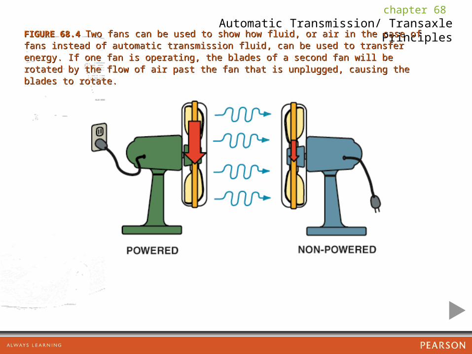
FIGURE 68.4 FIGURE 68.4 Two fans can be used to show how fluid, or air in the case of fans instead of Two fans can be used to show how fluid, or air in the case of fans instead of automatic transmission fluid, can be used to transfer energy. If one fan is operating, automatic transmission fluid, can be used to transfer energy. If one fan is operating, the blades of a second fan will be rotated by the flow of air past the fan that is the blades of a second fan will be rotated by the flow of air past the fan that is unplugged, causing the blades to rotate. unplugged, causing the blades to rotate.

chapter 68 Automatic Transmission/ Transaxle Principles
FIGURE 68.5 FIGURE 68.5 The torque converter bolts to the flexplate which is attached to the engine The torque converter bolts to the flexplate which is attached to the engine crankshaft and rotates at engine speed.crankshaft and rotates at engine speed.

chapter 68 Automatic Transmission/ Transaxle Principles
FIGURE 68.6 FIGURE 68.6 The flat sections that are cut into the hub of the torque converter are used The flat sections that are cut into the hub of the torque converter are used to drive the fluid pump.to drive the fluid pump.

chapter 68 Automatic Transmission/ Transaxle Principles
FIGURE 68.7 FIGURE 68.7 The internal splines inside the torque converter are connected to the The internal splines inside the torque converter are connected to the splines on the stator support shaft and the turbine splines to the input shaft.splines on the stator support shaft and the turbine splines to the input shaft.

chapter 68 Automatic Transmission/ Transaxle Principles
FIGURE 68.8 FIGURE 68.8 Torque multiplication occurs when fluid leaving the turbine strikes the front Torque multiplication occurs when fluid leaving the turbine strikes the front of the stator vanes and is redirected back to the impeller.of the stator vanes and is redirected back to the impeller.

chapter 68 Automatic Transmission/ Transaxle Principles
FIGURE 68.9 FIGURE 68.9 A stator contains a one-way roller clutch which locks it from rotating in one A stator contains a one-way roller clutch which locks it from rotating in one direction and allows it to rotate freely in the opposite direction.direction and allows it to rotate freely in the opposite direction.

chapter 68 Automatic Transmission/ Transaxle Principles
FIGURE 68.10 FIGURE 68.10 An expanded view of a typical torque converter assembly showing the An expanded view of a typical torque converter assembly showing the torque converter clutch (TCC).torque converter clutch (TCC).

chapter 68 Automatic Transmission/ Transaxle Principles
FIGURE 68.11 FIGURE 68.11 Torque converter clutch friction material is determined by the vehicle Torque converter clutch friction material is determined by the vehicle manufacturer to provide the needed coefficient of friction needed. For example, many manufacturer to provide the needed coefficient of friction needed. For example, many older units use a paper-type friction material because they are fully applied or older units use a paper-type friction material because they are fully applied or released, whereas most newer units use a synthetic material such as Kevlar® or released, whereas most newer units use a synthetic material such as Kevlar® or carbon fiber because the torque converter clutch is pulsed on and off, therefore carbon fiber because the torque converter clutch is pulsed on and off, therefore requiring a more robust material for long service life.requiring a more robust material for long service life.
chapter 68 Automatic Transmission/ Transaxle Principles
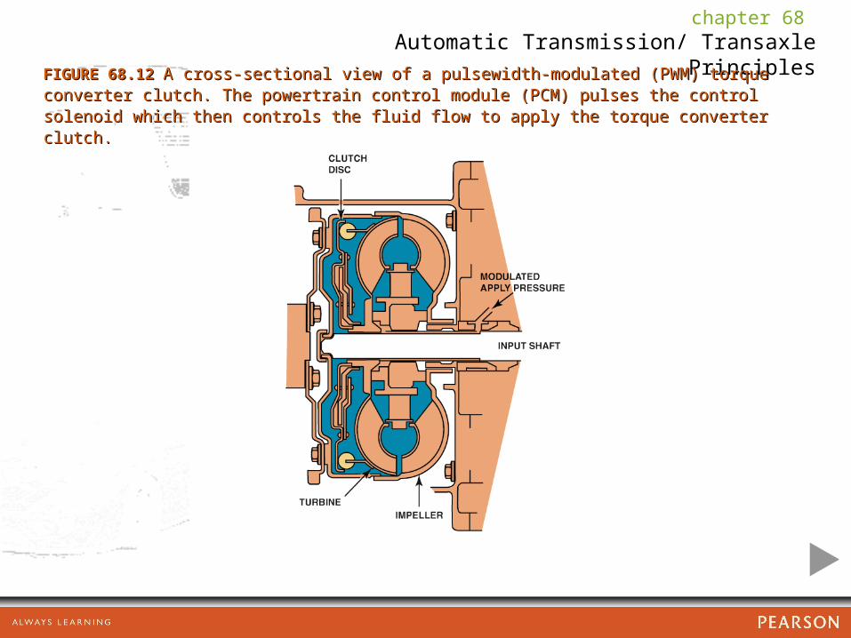
FIGURE 68.12 FIGURE 68.12 A cross-sectional view of a pulsewidth-modulated (PWM) torque converter A cross-sectional view of a pulsewidth-modulated (PWM) torque converter clutch. The powertrain control module (PCM) pulses the control solenoid which then clutch. The powertrain control module (PCM) pulses the control solenoid which then controls the fluid flow to apply the torque converter clutch. controls the fluid flow to apply the torque converter clutch.

chapter 68 Automatic Transmission/ Transaxle Principles
FIGURE 68.13 FIGURE 68.13 The gear selector is often called the “PRNDL,” pronounced “prindle,” The gear selector is often called the “PRNDL,” pronounced “prindle,” regardless of the actual letters or numbers used.regardless of the actual letters or numbers used.

chapter 68 Automatic Transmission/ Transaxle Principles
FIGURE 68.14 FIGURE 68.14 A typical planetary gear set showing the terms that are used to describe A typical planetary gear set showing the terms that are used to describe each member.each member.

chapter 68 Automatic Transmission/ Transaxle Principles
FIGURE 68.15 FIGURE 68.15 A typical planetary gear set showing the planet carrier which supports all A typical planetary gear set showing the planet carrier which supports all of the pinion gears (also called planet pinion gears).of the pinion gears (also called planet pinion gears).

chapter 68 Automatic Transmission/ Transaxle Principles
FIGURE 68.16 FIGURE 68.16 Maximum reduction can be achieved by using the sun gear as the input, Maximum reduction can be achieved by using the sun gear as the input, holding the ring gear and using the planet carrier as the output.holding the ring gear and using the planet carrier as the output.

chapter 68 Automatic Transmission/ Transaxle Principles
FIGURE 68.17 FIGURE 68.17 Minimum reduction can be achieved by using the ring gear as the input, Minimum reduction can be achieved by using the ring gear as the input, holding the sun gear and using the planet carrier as the output. holding the sun gear and using the planet carrier as the output.

chapter 68 Automatic Transmission/ Transaxle Principles
FIGURE 68.18 FIGURE 68.18 Reverse can be achieved by using the sun gear as the input, holding the Reverse can be achieved by using the sun gear as the input, holding the planet carrier and using the ring gear as the output.planet carrier and using the ring gear as the output.

chapter 68 Automatic Transmission/ Transaxle Principles
CHART 68.02CHART 68.02

chapter 68 Automatic Transmission/ Transaxle Principles
FIGURE 68.19 FIGURE 68.19 A Simpson planet gear set is composed of two ring gears and two planet A Simpson planet gear set is composed of two ring gears and two planet carrier assemblies that share one sun gear.carrier assemblies that share one sun gear.
chapter 68 Automatic Transmission/ Transaxle Principles
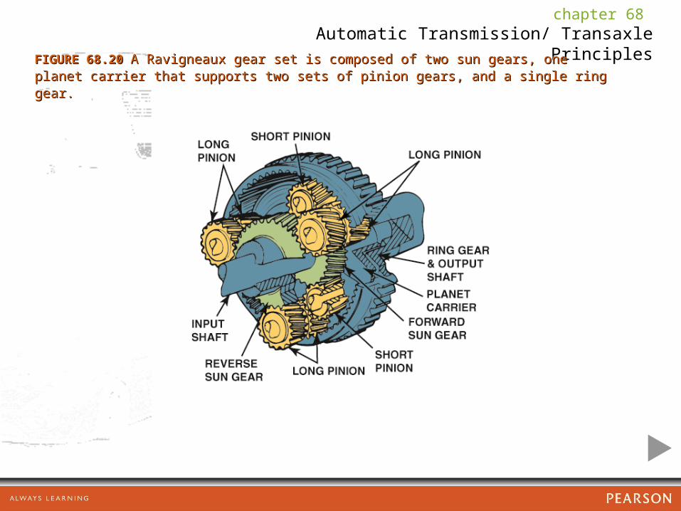
FIGURE 68.20 FIGURE 68.20 A Ravigneaux gear set is composed of two sun gears, one planet carrier A Ravigneaux gear set is composed of two sun gears, one planet carrier that supports two sets of pinion gears, and a single ring gear.that supports two sets of pinion gears, and a single ring gear.
chapter 68 Automatic Transmission/ Transaxle Principles
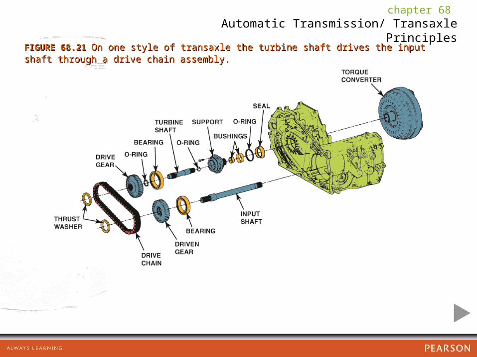
FIGURE 68.21 FIGURE 68.21 On one style of transaxle the turbine shaft drives the input shaft through a On one style of transaxle the turbine shaft drives the input shaft through a drive chain assembly.drive chain assembly.
chapter 68 Automatic Transmission/ Transaxle Principles
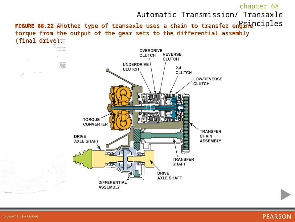
FIGURE 68.22 FIGURE 68.22 Another type of transaxle uses a chain to transfer engine torque from the Another type of transaxle uses a chain to transfer engine torque from the output of the gear sets to the differential assembly (final drive).output of the gear sets to the differential assembly (final drive).

chapter 68 Automatic Transmission/ Transaxle Principles
FIGURE 68.23 FIGURE 68.23 A cutaway showing the final drive assembly of a transaxle.A cutaway showing the final drive assembly of a transaxle.

chapter 68 Automatic Transmission/ Transaxle Principles
FIGURE 68.24 FIGURE 68.24 A Honda nonplanetary gear set type automatic transmission that uses A Honda nonplanetary gear set type automatic transmission that uses helical cut gears instead of planetary gears. Hydraulically applied clutches as helical cut gears instead of planetary gears. Hydraulically applied clutches as commanded by the PCM with fluid flow controlled by shift solenoids to make the shifts. commanded by the PCM with fluid flow controlled by shift solenoids to make the shifts.

chapter 68 Automatic Transmission/ Transaxle Principles
FIGURE 68.25 FIGURE 68.25 A belt and pulley CVT uses variable width pulleys and a special chain to A belt and pulley CVT uses variable width pulleys and a special chain to provide an infinite number of speed ratios.provide an infinite number of speed ratios.

chapter 68 Automatic Transmission/ Transaxle Principles
FIGURE 68.26 FIGURE 68.26 Honda CVT belt construction.Honda CVT belt construction.

chapter 68 Automatic Transmission/ Transaxle Principles
FIGURE 68.27 FIGURE 68.27 Honda CVT power flow in park (P) and neutral (N).Honda CVT power flow in park (P) and neutral (N).

chapter 68 Automatic Transmission/ Transaxle Principles
FIGURE 68.28 FIGURE 68.28 Honda CVT operation in drive (D) or low (L).Honda CVT operation in drive (D) or low (L).

chapter 68 Automatic Transmission/ Transaxle Principles
FIGURE 68.29 FIGURE 68.29 Location of the Honda CVT start clutch.Location of the Honda CVT start clutch.
chapter 68 Automatic Transmission/ Transaxle Principles
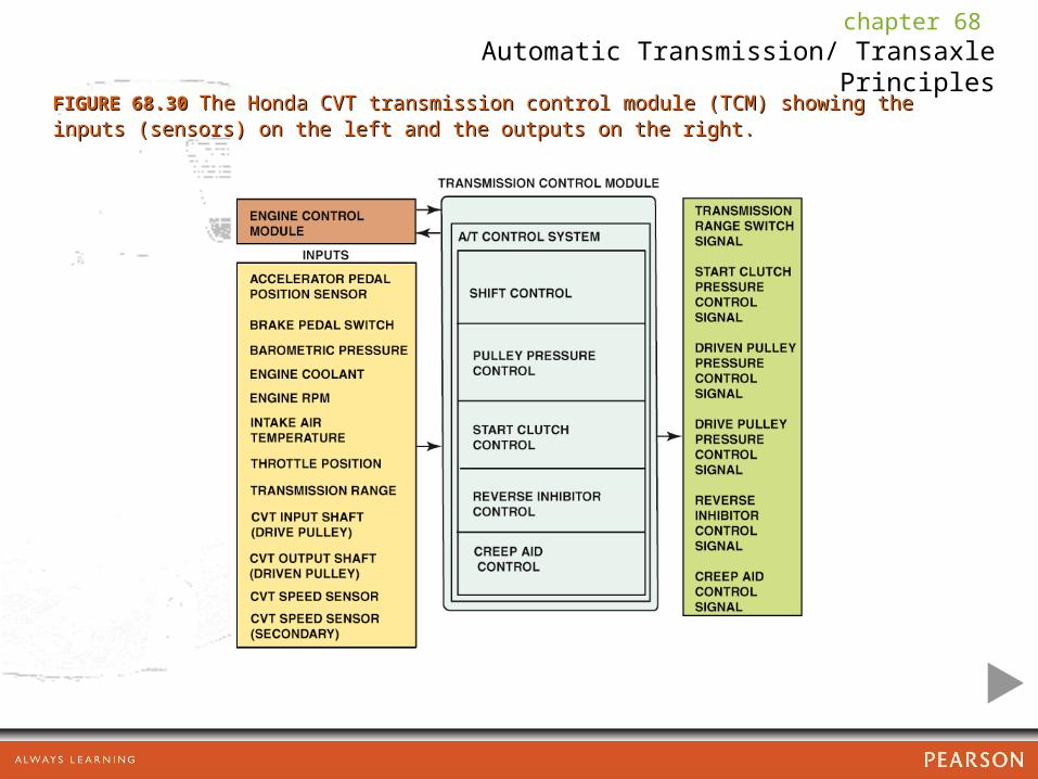
FIGURE 68.30 FIGURE 68.30 The Honda CVT transmission control module (TCM) showing the inputs The Honda CVT transmission control module (TCM) showing the inputs (sensors) on the left and the outputs on the right.(sensors) on the left and the outputs on the right.

chapter 68 Automatic Transmission/ Transaxle Principles
FIGURE 68.31 FIGURE 68.31 A dual clutch automatic uses the best features of an automatic A dual clutch automatic uses the best features of an automatic transmission without the power loss of a torque converter.transmission without the power loss of a torque converter.

chapter 68 Automatic Transmission/ Transaxle Principles
FIGURE 68.32 FIGURE 68.32 Dual clutch automatic transaxles that use two dry clutches. The larger Dual clutch automatic transaxles that use two dry clutches. The larger clutch drives the odd number gear ratios (first, third, and fifth) and the smaller clutch clutch drives the odd number gear ratios (first, third, and fifth) and the smaller clutch drives the even numbered gear ratios (second, fourth, and sixth). drives the even numbered gear ratios (second, fourth, and sixth).