ase 2 - automatic transmission & transaxle - ccbc...
TRANSCRIPT

ASE 2 - Automatic Transmission &Transaxle
Module 4Apply Devices

AcknowledgementsGeneral Motors, the IAGMASEP Association Board of Directors, and RaytheonProfessional Services, GM's training partner for GM's Service Technical College wish tothank all of the people who contributed to the GM ASEP/BSEP curriculum developmentproject 2002-3. This project would not have been possible without the tireless efforts ofmany people. We acknowledge:
• The IAGMASEP Association members for agreeing to tackle this large project tocreate the curriculum for the GM ASEP/BSEP schools.
• The IAGMASEP Curriculum team for leading the members to a single vision andimplementation.
• Direct contributors within Raytheon Professional Services for their support oftranslating a good idea into reality. Specifically, we thank:
– Chris Mason and Vince Williams, for their leadership, guidance, and support.– Media and Graphics department under Mary McClain and in particular, Cheryl
Squicciarini, Diana Pajewski, Lesley McCowey, Jeremy Pawelek, & NancyDeSantis.
– For his help on the Automatic Transmission curriculum volume, Subject MatterExpert, Bob Hayes, for his wealth of knowledge.
Finally, we wish to recognize the individual instructors and staffs of the GM ASEP/BSEPColleges for their contribution for reformatting existing General Motors training material,adding critical technical content and the sharing of their expertise in the GM product.Separate committees worked on each of the eight curriculum areas. For the work on thisvolume, we thank the members of the Automatic Transmission committee:
– George Aiken, Raytheon– Jerry Darnell, Guilford Technical Community College– Rick Frazier, Owens Community College– Stevon Gregory, Oklahoma State University - Okmulgee– Sumner Huckaby, Greenville Technical College– Marvin Johnson, Brookhaven College– Scott Main, Shoreline Community College– Tim McCluskey, Dakota County Technical College– Larry Thomas, College of Southern Nevada

ContentsModule 4 – Apply DevicesAcknowledgements .......................................................................................... 2Introduction ...................................................................................................... 4Objectives ........................................................................................................ 4
Lesson 1. Basic Hydraulics ............................................................................................. 5Clutches .......................................................................................................................... 7Driving ............................................................................................................................. 8Servos ........................................................................................................................... 10Holding .......................................................................................................................... 12Mechanical Clutches ..................................................................................................... 13Range Reference Chart ................................................................................................ 15Seals and O-rings ......................................................................................................... 16

© 2002 General Motors CorporationAll Rights Reserved
ASE 2 - AutomaticTransmission &Transaxle
Module 4 - ApplyDevices
4-4
Student WorkbookIntroductionThe Apply Devices section explains the function of the hydraulic andmechanical holding devices used in automatic transmissions.Some of these apply components, such as clutches and bands, arehydraulically “applied” and “released” in order to provide automatic gearrange shifting. Other components, such as a roller clutch or sprag clutchare mechanical and often react to a hydraulically applied component bymechanically holding or releasing another member of the transmission
ObjectivesNATEF Area II.1. Research applicable vehicle and service information, such as
transmission/transaxle system operation, vehicle service history,service precautions, and technical service bulletins.
2. Inspect and replace external seals and gaskets.3. Inspect servo bore, piston, seals, pin, spring, and retainers; determine
necessary action.

© 2002 General Motors CorporationAll Rights Reserved
ASE 2 - AutomaticTransmission &Transaxle
Module 4 - ApplyDevices
4-5
Student WorkbookLesson 1. Basic HydraulicsPascal's LawIn the seventeenth century. Pascal, a French scientist. discovered thehydraulic lever. In laboratory experiments he proved that force and motioncould be transferred by means of a confined liquid. Experimenting withweights and pistons of varying size. Pascal also found that mechanicaladvantage or force multiplication could be obtained in a pressure systemand that the relationships between force and distance were exactly thesame as with a mechanical lever. From the data Pascal collected, heformulated a law, which states:Pressure on a confined fluid is transmitted equally in all directions andacts with equal force on equal areas.So the basic idea behind any hydraulic system is very simple: Force that isapplied at one point is transmitted to another point using anincompressible fluid. The fluid is almost always an oil of some sort. Theforce is almost always multiplied in the process. The picture below showsthe simplest possible hydraulic system:
Figure 4-1,
In this drawing, two pistons (red) fit into two glass cylinders filled with oil(light blue) and connected to one another with an oil-filled pipe. If youapply a downward force to one piston (the left one in this drawing), thenthe force is transmitted to the second piston through the oil in the pipe.Since oil is incompressible, the efficiency is very good – almost all of theapplied force appears at the second piston.The neat thing about hydraulic systems is that it is very easy to add forcemultiplication (or division) to the system. If you know how gears work, thenyou know that trading force for distance is very common in mechanicalsystems. In a hydraulic system, all you do is change the size of one pistonand cylinder relative to the other, as shown here:

© 2002 General Motors CorporationAll Rights Reserved
ASE 2 - AutomaticTransmission &Transaxle
Module 4 - ApplyDevices
4-6
Student Workbook
Figure 4-2,
Hydraulic MultiplicationThe piston on the right has a surface area nine times greater than thepiston on the left. When force is applied to the left piston, it will move nineunits for every one unit that the right piston moves, and the force ismultiplied by nine on the right-hand piston.
To determine the multiplication factor, start by looking at the size of thepistons. Assume that the piston on the left is 2 inches in diameter (1-inchradius), while the piston on the right is 6 inches in diameter (3-inch radius).The area of the two pistons is Pi * r2. The area of the left piston istherefore 3.14, while the area of the piston on the right is 28.26. Thepiston on the right is 9 times larger than the piston on the left. What thatmeans is that any force applied to the left-hand piston will appear 9 timesgreater on the right-hand piston. So if you apply a 100-pound downwardforce to the left piston, a 900-pound upward force will appear on the right.The only catch is that you will have to depress the left piston 9 inches toraise the right piston 1 inch. One thing you always want to remember isyou don't get anything for free, if you want lifting power you give up stroke.
© 2002 General Motors CorporationAll Rights Reserved
ASE 2 - AutomaticTransmission &Transaxle
Module 4 - ApplyDevices
4-7
Student WorkbookClutchesMultiple DiskMost multiple disk clutches are constructed by using some or all of thefollowing components, apply clutch pistons, pressure plates, wavy plates,steel clutch plates, fiber clutch plates, backing plates, checkballs, returnsprings and returned spring assemblies.
Apply clutch pistonApply clutch piston is the hydraulic device that has seals and/or gasketsthat apply pressure to the multiple disk clutch assembly.
Pressure plateThe pressure plate is a heavy steel plate that provides a clamping surfacefor the multiple plate clutch. It can be installed in either the front or theback of the clutch assembly.
Wavy platesWavy plates are used to give a cushioned apply of the clutch assembly.They are steel plates that are wavy instead of flat.
Steel clutch platesSteel clutch plates are flat steel plates in a multiple clutch assembly.
Fiber platesFiber plates are flat steel plates lined with a friction material in a multipleclutch assembly.
Backing platesBacking plates are thick steel plates that the whole clutch assemblypushes against and they are very thick steel plates that are the farthestaway from the piston.
CheckballsCheckballs are balls that control oil flow in and out of the clutch assembly.
Return springs and returned spring assembliesReturn springs and returned spring assemblies are the springs orassemblies that return the piston to its resting position to give a completerelease.

© 2002 General Motors CorporationAll Rights Reserved
ASE 2 - AutomaticTransmission &Transaxle
Module 4 - ApplyDevices
4-8
Student WorkbookDriving
Figure 4-3,
Figure 4-4,

© 2002 General Motors CorporationAll Rights Reserved
ASE 2 - AutomaticTransmission &Transaxle
Module 4 - ApplyDevices
4-9
Student Workbook2nd ClutchThe 2nd clutch assembly (617-627), located between the driven sprocketsupport (609) and the input clutch assembly (631-659), is applied or "ON"during Second, Third and Fourth Gear Ranges as well as Manual Thirdand Manual Second Gear Ranges.
2nd Clutch ApplyTo apply the 2nd clutch, 2nd clutch apply fluid is fed through the drivensprocket support (609) to the inner hub of the 2nd clutch housing (617).Feed holes in the hub allows 2nd clutch apply fluid to enter the 2nd clutchhousing (617) behind the 2nd clutch piston (620); seats the retainer andball assembly (618) and moves the piston to compress the apply ring &release spring assembly (621). The piston continues to move,compressing the 2nd clutch wave plate (623), until the 2nd clutch applyplate (716), 2nd clutch reaction plates (625) and 2nd clutch plateassemblies (624) are held against the backing support ring plate (626).When fully applied, the 2nd clutch provides the power to the gear sets(672 & 675) through the: waved plate (623); (steel) tapered apply reactionplate (716); (steel) reaction plates (625) external teeth splined to the 2ndclutch housing (617); and, the 2nd clutch plate assemblies (624) internalteeth splined to the hub on the input housing assembly (631-659).
2nd Clutch Release:To release the 2nd clutch assembly (621-627), 2nd clutch apply fluidpressure exhausts through the apply passages in the inner hub of the 2ndclutch housing (617) and driven sprocket support (609). In the absence offluid pressure, the apply ring & release spring assembly (621) move the2nd clutch piston (620) and releases the 2nd clutch reaction plates (625 &716) and 2nd clutch plate assemblies (624) from contact with the backingsupport ring plate (626).During the release of the 2nd clutch fluid, the retainer & ball assembly(618), located in the 2nd clutch housing (617), unseats. Centrifugal force,resulting from the rotation of the 2nd clutch housing (617), unseats thecheckball and forces residual 2nd clutch fluid to the outside of the pistonhousing and through the unseated retainer & ball assembly (618). If thisfluid did not completely exhaust from behind the piston, there could be apartial apply, or drag, of the 2nd clutch plates.

© 2002 General Motors CorporationAll Rights Reserved
ASE 2 - AutomaticTransmission &Transaxle
Module 4 - ApplyDevices
4-10
Student WorkbookServosServo Assembly and 2-4 Band
The servo assembly and 2-4 band (602) are located in the front of thetransmission case and applied in Second and Fourth gears. In Third gear,the servo assembly releases the band and acts as an accumulator for the3-4 clutch apply. The band is held stationary to the transmission case bythe band anchor pin (49) and wraps around the reverse input housing(605). When compressed by the servo assembly, the 2-4 band holds thereverse input housing stationary to the transmission case. No upshift in 1stgear could be caused by a worn or damaged 2-4 band or if the bandanchor pin is not engaged.
Figure 4-5,
Figure 4-6,
2-4 Band Applied - Second GearTo apply the 2-4 band in Second gear, 2ndclutch fluid is routed to the apply side ofthe 2nd apply piston (17). 2nd clutch fluidpressure moves the piston against servocushion (16) and servo return (12) springforces. These spring forces help cushionthe 2-4 band apply in Second gear. The2nd apply piston moves the apply pin (13)to compress the band around the reverseinput housing.

© 2002 General Motors CorporationAll Rights Reserved
ASE 2 - AutomaticTransmission &Transaxle
Module 4 - ApplyDevices
4-11
Student Workbook2-4 Band Release and 3-4 Clutch AccumulationIn Third gear, 3rd accumulator fluid is routed to the release side of the 2ndapply piston. The surface area on the release side of the 2nd apply piston(17) and servo cushion spring retainer (15) is greater than the surfacearea that 2nd clutch fluid pressure covers on the apply side of the piston.Therefore, the force from 3rd accumulator fluid pressure, in addition toservo return spring (12) force, overcomes the force of 2nd clutch fluidpressure. The 2nd apply piston then moves the apply pin (13) away fromthe 2-4 band to release the band from the reverse input housing.3rd accumulator fluid is fed by 3-4 clutch fluid which is used to apply the3-4 clutch. The movement of the 2nd apply piston against 2nd clutch fluidpressure acts as an accumulator to absorb initial 3-4 clutch apply fluid.This action helps cushion the 3-4 clutch apply, as well as release the2-4 band.
Figure 4-7,
2-4 Band Applied - Fourth GearIn Fourth gear, 4th fluid is routed through the center of the apply pin andacts on the apply side of the 4th apply piston (25). 4th fluid pressuremoves the 4th apply piston (25) and apply pin (13) to apply the band. The4th apply piston moves against the 4th apply spring (22) to help cushionthe band apply in Fourth gear.
Figure 4-8,
© 2002 General Motors CorporationAll Rights Reserved
ASE 2 - AutomaticTransmission &Transaxle
Module 4 - ApplyDevices
4-12
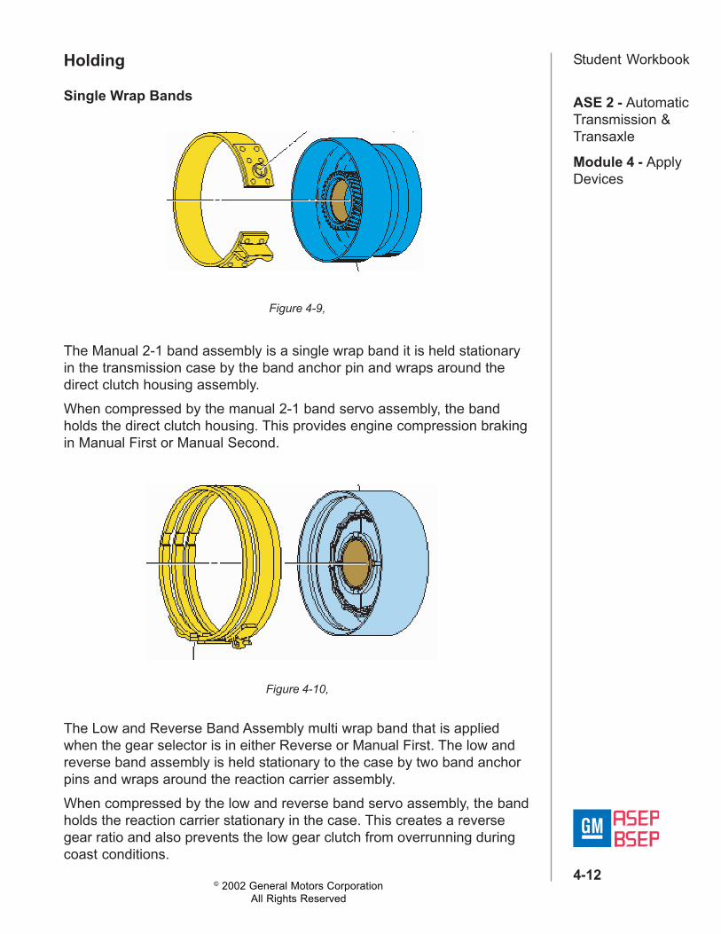
Student WorkbookHolding
The Manual 2-1 band assembly is a single wrap band it is held stationaryin the transmission case by the band anchor pin and wraps around thedirect clutch housing assembly.When compressed by the manual 2-1 band servo assembly, the bandholds the direct clutch housing. This provides engine compression brakingin Manual First or Manual Second.
Figure 4-9,
Single Wrap Bands
Figure 4-10,
The Low and Reverse Band Assembly multi wrap band that is appliedwhen the gear selector is in either Reverse or Manual First. The low andreverse band assembly is held stationary to the case by two band anchorpins and wraps around the reaction carrier assembly.When compressed by the low and reverse band servo assembly, the bandholds the reaction carrier stationary in the case. This creates a reversegear ratio and also prevents the low gear clutch from overrunning duringcoast conditions.

© 2002 General Motors CorporationAll Rights Reserved
ASE 2 - AutomaticTransmission &Transaxle
Module 4 - ApplyDevices
4-13
Student WorkbookMechanical ClutchesSprag Clutches
Figure 4-11,
A sprag assembly is shown in the holding and released positions. Whenholding, the rotation of the outer race pivots the sprags towards their longdiagonals.The length of the long diagonal is greater than the distance between theouter race and inner race. This causes the sprags to lock between theinner and outer races and transfer torque from the outer forward spragclutch face to the inner sprag clutch race and to the input sun gear.The sprag clutch is released when the sprag pivots toward their shortdiagonal. The length of the short diagonals is less than the distancebetween the inner and outer sprag races. This occurs when thepowerflow drives the input retainer assembly faster than the forwardRoller Clutchesclutch race.

© 2002 General Motors CorporationAll Rights Reserved
ASE 2 - AutomaticTransmission &Transaxle
Module 4 - ApplyDevices
4-14
Student WorkbookRoller Clutches
Figure 4-12,
2nd Roller Clutch:The 2nd roller clutch, located between the driven sprocket support andreverse clutch housing, holds the reverse clutch housing whenever thetransaxle is operating in Second gear.2nd Roller Clutch Assembly Holding (the reaction sun gear):The 2nd clutch assembly has fiber plates with internal teeth splined to the2nd roller clutch cam, and steel plates that are splined to the case. The2nd roller clutch inner race is part of the reverse clutch housing (454),which rotates in the opposite direction of engine rotation during First gearoperation. When the 2nd clutch applies, internal teeth on the 2nd clutchfiber plates hold the 2nd roller clutch cam stationary. The reverse clutchhousing is then prevented from rotating in a direction opposite to enginerotation because the rollers are forced to wedge between the inner raceand lowest part of the cam ramps. When the 2nd roller clutch ismechanically locked up, it holds the reaction sun gear and shell assemblythrough the reverse clutch housing. This arrangement directs power flowto the reaction carrier assembly in Second gear.2nd Roller Clutch Assembly Released:The 2nd roller clutch assembly releases whenever the 2nd clutchreleases, or its rollers "overrun" (freewheel). An overrunning conditionoccurs whenever the transaxle operates in Third gear where the 2ndclutch is not used for power flow through the gear sets. While operating inThird gear, the reverse clutch housing rotates in the direction of enginerotation. When this occurs, the rollers are forced to rotate in the oppositedirection which disengages the inner race from the outer cam. The rollersfreewheel when this condition occurs. Roller clutch damaged, not holdingcan cause no Overdrive range second/slips in second.Note: Manual second will be available.

© 2002 General Motors CorporationAll Rights Reserved
ASE 2 - AutomaticTransmission &Transaxle
Module 4 - ApplyDevices
4-15
Student WorkbookRange Reference Chart
Figure 4-13,

© 2002 General Motors CorporationAll Rights Reserved
ASE 2 - AutomaticTransmission &Transaxle
Module 4 - ApplyDevices
4-16
Student WorkbookThe Range Reference Chart provides another valuable source ofinformation for explaining the overall function of any transmission ortransaxle. This chart highlights the major apply components that functionin a selected gear range, and the specific gear operation within that gearrange. Included as part of this chart is the same color reference to eachmajor component that was previously discussed. If a component is activein a specific gear range, a word describing its activity will be listed in thecolumn below that component. The row where the activity occurscorresponds to the appropriate transaxle range and gear operation. Anabbreviated version of this chart can also be found at the top of the halfpage of text located in the Power Flow section. This provides for a quickreference when reviewing the mechanical power flow informationcontained in that section.
Seals and O-ringsStatic sealStatic seal is a seal used between two parts that do not move inrelationship to each other.Dynamic sealA dynamic seal is a seal that is used between two parts that do move inrelationship to each other this movement is either rotating or reciprocatingup-and-down motion.A positive sealA positive seal is a seal that prevents all fluid from leaking between twoparts.Non-positive sealNon-positive seal is a seal that allows a controlled amount of fluid to leakfrom between two parts.These components are sealed with rings seals. Rings seals fit onto agroove shaft. The outside diameter of the ring, slide against the walls of abore into which a shaft is inserted. Most rings seals of the transmissionare placed near pressurize fluid outlets on rotating shaft helped to retainpressure. Ring seals are made of cast-iron, nylon, or Teflon.Three major type of rubber seals are used in automatic transmissions: theo-ring, the lip seal, and the square cut seal.O-rings are seals with a circular cross-section.Square cut seal are similar to O-ring however the square cut seal canwithstand more axial movement that 0-ring can.Lip seals are used to seal parts that have axial or rotational movement.