automated inspection with machine vision · automated inspection with machine vision part 1...
TRANSCRIPT

Copyright © 2016. ConsulTech Engineering, PLLC. All rights reserved.
Automated Inspection
With
Machine VisionPart 3
Stanley N. Hack, D.Sc., PE
ConsulTech Engineering, PLLC
www.consultechusa.com
November 7, 2016

2Copyright © 2016. ConsulTech Engineering, PLLC. All rights reserved.
PRESENTATION GOALS
• Understanding Machine Vision and Its Uses
• Understanding Machine Vision Components
• Appreciating the Interacting Complexities of Machine Vision Components and Processing
Disclaimer:
• Most of ConsulTech Engineering’s clients regard their processes, which
include machine vision applications, as highly proprietary.
• Many of the applications presented have been devised for this presentation.
3Copyright © 2016. ConsulTech Engineering, PLLC. All rights reserved.
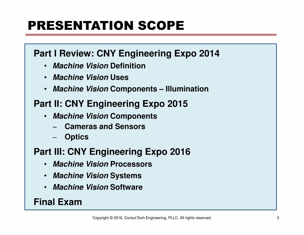
PRESENTATION SCOPE
Part I Review: CNY Engineering Expo 2014
• Machine Vision Definition
• Machine Vision Uses
• Machine Vision Components – Illumination
Part II: CNY Engineering Expo 2015
• Machine Vision Components
− Cameras and Sensors
− Optics
Part III: CNY Engineering Expo 2016
• Machine Vision Processors
• Machine Vision Systems
• Machine Vision Software
Final Exam

4Copyright © 2016. ConsulTech Engineering, PLLC. All rights reserved.
MACHINE VISION DEFINTION
Machine Vision is defined as the technology and methods used to automatically inspect materials, components, and manufactured systems using image-based sensors and systems.
Key Words
• Automatic Inspection
• Materials, Components, Manufactured Systems
• Image-Based

5Copyright © 2016. ConsulTech Engineering, PLLC. All rights reserved.
MACHINE VISION DEFINITION
Machine Vision has the following attributes:
• The input is an image, and the output is a set of data, such as feature
existence, object type, object or feature location, and measurements.
• The system analyzes inanimate objects.
• The system has a priori knowledge of the imaged object(s), including
object shape, size, position, and attributes.
• The system performs its processing repeatedly and often rapidly.
• The imaging environment, including illumination, geometry, and
motion, is controlled by the Machine Vision system.
6Copyright © 2016. ConsulTech Engineering, PLLC. All rights reserved.
MACHINE VISION ENVIRONMENT
Machine Vision is unique among all of the computer imaging modalities (computer vision, image processing,
medical imaging, remote sensing) in that many aspects of the imaging environment can often be controlled
• Illumination
• Sensor positioning
• Sensor size and resolution
• Image magnification and orientation
• Optical filtering
• Reflections
A large component of Machine Vision system design is the optimization of the captured images to make the software’s job feasible, easier, and/or faster.
7Copyright © 2016. ConsulTech Engineering, PLLC. All rights reserved.
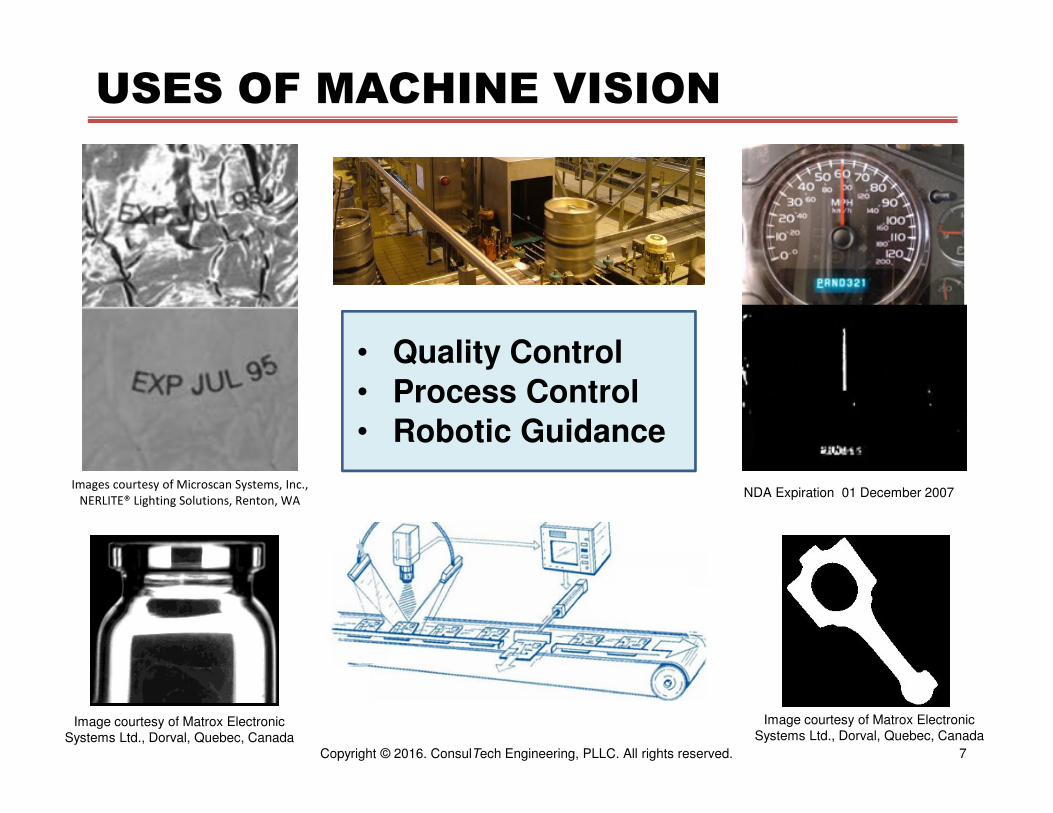
USES OF MACHINE VISION
• Quality Control
• Process Control
• Robotic Guidance
NDA Expiration 01 December 2007
Image courtesy of Matrox Electronic
Systems Ltd., Dorval, Quebec, Canada
Image courtesy of Matrox Electronic
Systems Ltd., Dorval, Quebec, Canada
Images courtesy of Microscan Systems, Inc.,
NERLITE® Lighting Solutions, Renton, WA

8Copyright © 2016. ConsulTech Engineering, PLLC. All rights reserved.
MACHINE VISION COMPONENTS
Work station image courtesy of Comark LLC, Milford, MA
• Cameras and Sensors
• Optics
• Illumination
• Synchronization
• Processing
• Reporting

9Copyright © 2016. ConsulTech Engineering, PLLC. All rights reserved.
Review – Illumination
Automated Inspection with Machine Vision Part 1 summarized in two theorems:
Theorem 1
If adding shadows to a captured image helps the processing, configure the illumination to add the appropriate shadowing.
Theorem 2
If shadows in a captured image hurts the processing, configure the illumination to remove shadowing.
Figures courtesy of Illumination Technologies, Elbridge, NY

10Copyright © 2016. ConsulTech Engineering, PLLC. All rights reserved.
Review – Illumination
Imaging Geometry
• On-axis or coaxial
• Partial bright field or directional • Back lighting
• Diffuse, dome, or cloudy day
• Dark field
• Structured
Figures from - A Practical Guide to
Machine Vision Lighting, Daryl Martin,
Advanced Illumination, Inc., 2007
11Copyright © 2016. ConsulTech Engineering, PLLC. All rights reserved.
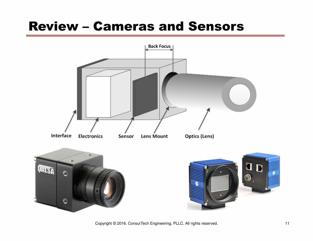
Review – Cameras and Sensors
12Copyright © 2016. ConsulTech Engineering, PLLC. All rights reserved.
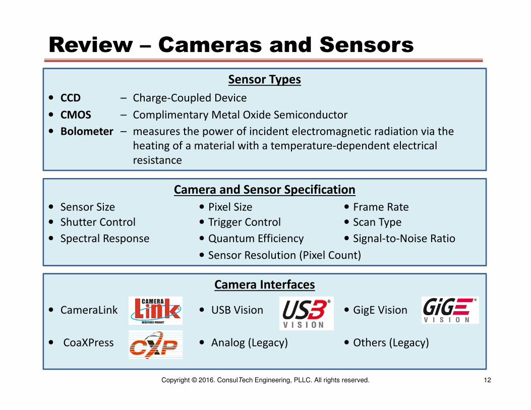
Review – Cameras and Sensors
Sensor Types
• CCD – Charge-Coupled Device
• CMOS – Complimentary Metal Oxide Semiconductor
• Bolometer – measures the power of incident electromagnetic radiation via the
heating of a material with a temperature-dependent electrical
resistance
Camera and Sensor Specification
• Sensor Size • Pixel Size • Frame Rate
• Shutter Control • Trigger Control • Scan Type
• Spectral Response • Quantum Efficiency • Signal-to-Noise Ratio
• Sensor Resolution (Pixel Count)
Camera Interfaces
• CameraLink • USB Vision • GigE Vision
• CoaXPress • Analog (Legacy) • Others (Legacy)
13Copyright © 2016. ConsulTech Engineering, PLLC. All rights reserved.
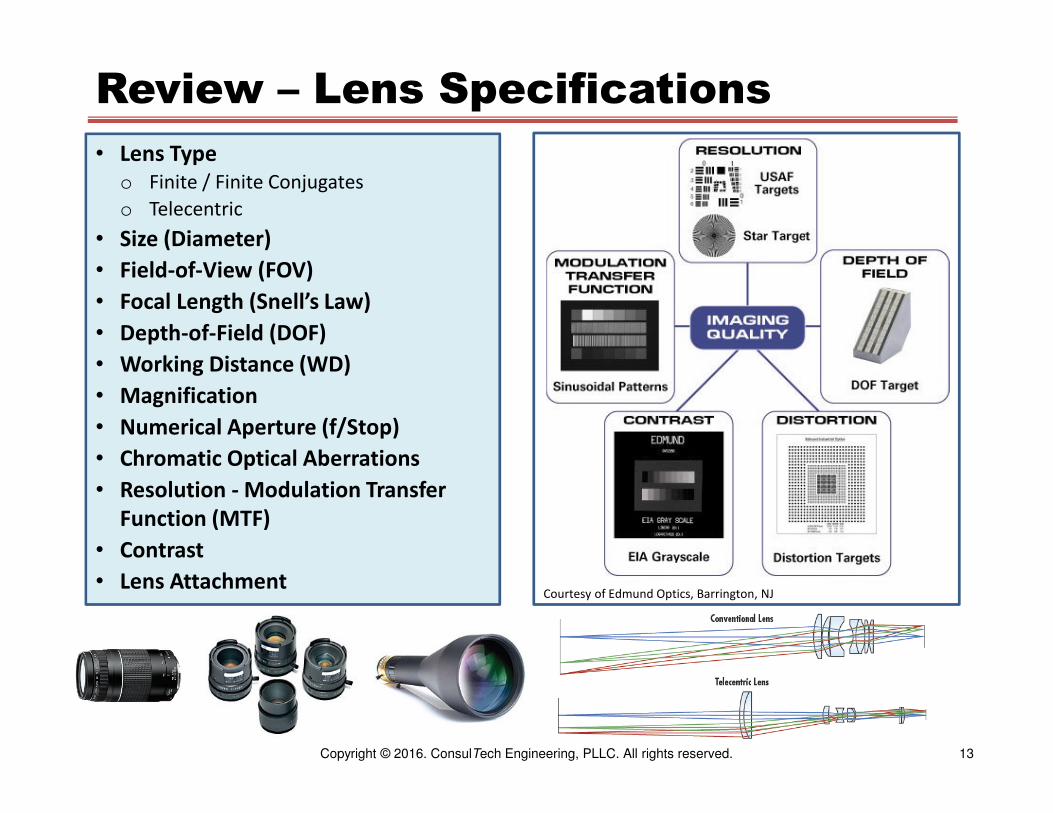
Review – Lens Specifications
• Lens Type
o Finite / Finite Conjugates
o Telecentric
• Size (Diameter)
• Field-of-View (FOV)
• Focal Length (Snell’s Law)
• Depth-of-Field (DOF)
• Working Distance (WD)
• Magnification
• Numerical Aperture (f/Stop)
• Chromatic Optical Aberrations
• Resolution - Modulation Transfer
Function (MTF)
• Contrast
• Lens AttachmentCourtesy of Edmund Optics, Barrington, NJ

14Copyright © 2016. ConsulTech Engineering, PLLC. All rights reserved.
Machine Vision Processors
• Personal Computer (PC)
o Inexpensive, fast, multiple sources
o Intel Multi-Core architecture permits multi-processing
o Packaging options – workstation, fanless, server
• Other Platforms
o Graphical Processing Unit (GPU)
o Field-Programmable Logic Array (FPGA)
o Systems on a Chip (SoC)
• Smart Cameras
• Camera Interfaces (Frame Grabbers)
Smart Cameras
High-Performance PC (Server Class) Fanless PC

15Copyright © 2016. ConsulTech Engineering, PLLC. All rights reserved.
Machine Vision Software Packages
• Libraries
o HALCON – MVTec Software, GmbH, Munich, Germany, www.mvtec.com
o MIL – Matrox Electronic Systems Ltd., Dorval, Quebec, Canada,
www.matrox.com
o Sapera – Teledyne Dalsa, Inc., Waterloo, ON, Canada,
www.teledynedalsa.com
o OpenCV – www.opencv.org
o ImageJ – https://imagej.nih.gov/ij/
• Graphical
o LabView – National Instruments Corporation, Austin, TX, www.ni.com
o MERLIC – MVTec Software, GmbH, Munich, Germany, www.mvtec.com
o Design Assistant – Matrox Electronic Systems Ltd., Dorval, Quebec, Canada,
www.matrox.com
• Hybrid
o Sherlock – Teledyne Dalsa , Inc., Waterloo, ON, Canada,
www.teledynedalsa.com
o Vision Editor – Keyence Corporation of America, Itasca, IL, www.keyence.com

16Copyright © 2016. ConsulTech Engineering, PLLC. All rights reserved.
Machine Vision Software Packages
Matrox
Design
Assistant

17Copyright © 2016. ConsulTech Engineering, PLLC. All rights reserved.
Machine Vision Software Packages
Dalsa
Sherlock

18Copyright © 2016. ConsulTech Engineering, PLLC. All rights reserved.
Machine Vision Software
• Image Acquisition – Grab image(s) from camera(s)
o Synchronize with material handling system
o Synchronize with or control illumination (optional)
• Image Pre-Processing
o Point Processes – Gray-level adjustments
o Arithmetic – Combination of two or more images
o Spatial Filters – Convolution and Morphology
o Geometric Transforms – Alignment
• Feature Segmentation – Separate features of interest from background
• Feature Analysis
o Measure and compare to specifications
o Pattern matching
o Locate artifacts (debris, flaws, missing features, …)
• Reporting
o Control material handling
o Communicate to operators and servers
o Generate logs

19Copyright © 2016. ConsulTech Engineering, PLLC. All rights reserved.
Software – Image Representation
0 m - 1
0
n - 1
j
pixel(i, j) where:
0 <= i < m
0 <= j < n
columni
r
o
w
Pixel Values
black gray white
0 N - 1

20Copyright © 2016. ConsulTech Engineering, PLLC. All rights reserved.
Software – Point Preprocessing
Point
Process
• Contrast stretching
o Min / Max
o Mean / Standard Deviation
• Histogram Equalization
• Cutoff
• Saturate
• Threshold – create binary
image
Point Process Applications
• For visualization of images
taken under different lighting
conditions – Example:
Stitching together a mosaic of
image for remote sensing
• Normalization of images
when automatic comparison
operations are used
f(x,y) g(x,y)
g(i,j) = F( f(i,j) )

21Copyright © 2016. ConsulTech Engineering, PLLC. All rights reserved.
Software – Point Preprocessing
0
200
400
600
800
1000
1200
1400
1 8
15
22
29
36
43
50
57
64
71
78
85
92
99
10
6
11
3
12
0
12
7
13
4
14
1
14
8
15
5
16
2
16
9
17
6
18
3
19
0
19
7
20
4
21
1
21
8
22
5
23
2
23
9
24
6
25
3
Primary Tool For Point Processing: Gray-Level Histogram
Gray-Levels
C
o
u
n
t
A gray-level histogram is a plot showing the number
of pixels containing each gray-level in an image.

22Copyright © 2016. ConsulTech Engineering, PLLC. All rights reserved.
0
1000
2000
3000
4000
5000
6000
1
12
23
34
45
56
67
78
89
10
0
11
1
12
2
13
3
14
4
15
5
16
6
17
7
18
8
19
9
21
0
22
1
23
2
24
3
25
4
Software – Point Preprocessing
Original
Stretched – Move and Combine Histogram Bins
0
1000
2000
3000
4000
5000
6000
1
12
23
34
45
56
67
78
89
10
0
11
1
12
2
13
3
14
4
15
5
16
6
17
7
18
8
19
9
21
0
22
1
23
2
24
3
25
4
Min/Max Contrast Stretching
23Copyright © 2016. ConsulTech Engineering, PLLC. All rights reserved.
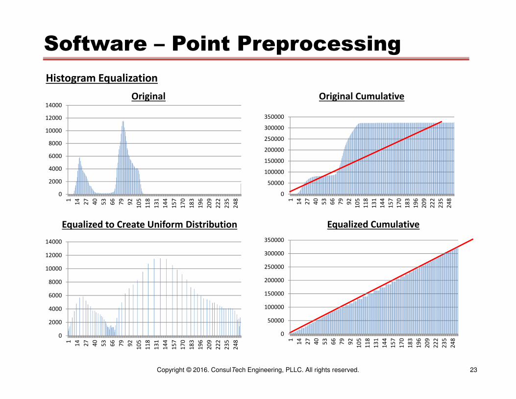
Software – Point Preprocessing
Original
Equalized to Create Uniform Distribution
Histogram Equalization
0
2000
4000
6000
8000
10000
12000
14000
1
14
27
40
53
66
79
92
10
5
11
8
13
1
14
4
15
7
17
0
18
3
19
6
20
9
22
2
23
5
24
8
0
50000
100000
150000
200000
250000
300000
350000
1
14
27
40
53
66
79
92
10
5
11
8
13
1
14
4
15
7
17
0
18
3
19
6
20
9
22
2
23
5
24
8
Original Cumulative
0
2000
4000
6000
8000
10000
12000
14000
1
14
27
40
53
66
79
92
10
5
11
8
13
1
14
4
15
7
17
0
18
3
19
6
20
9
22
2
23
5
24
8
0
50000
100000
150000
200000
250000
300000
350000
1
14
27
40
53
66
79
92
10
5
11
8
13
1
14
4
15
7
17
0
18
3
19
6
20
9
22
2
23
5
24
8
Equalized Cumulative

24Copyright © 2016. ConsulTech Engineering, PLLC. All rights reserved.
Software – Point Preprocessing
Original Image Histogram Stretch Histogram Equalization
Original Image Histogram Stretch Histogram Equalization
Note bright reflections at tops of pins

25Copyright © 2016. ConsulTech Engineering, PLLC. All rights reserved.
Software – Point Preprocessing
Original Image – Red = Dark Image
Blue = Light Image
Original Image – Histogram Difference
(Light Image – Dark Image)
Histogram Equalized – Red = Dark Image
Blue = Light Image
Histogram Equalized – Histogram Difference
(Light – Dark)

26Copyright © 2016. ConsulTech Engineering, PLLC. All rights reserved.
Software – Arithmetic Preprocessing
+
-
AND
OR
MIN
MAX●
●
●
=
Pixel-By-Pixel Arithmetic, Logic, or Masking
=
+
-
AND
OR
MIN
MAX●
●
●
Constant
f1(x,y) f2(x,y) g(x,y) = F( f1(x,y), f1(x,y) )
g(x,y) = F( f1(x,y), C)
27Copyright © 2016. ConsulTech Engineering, PLLC. All rights reserved.
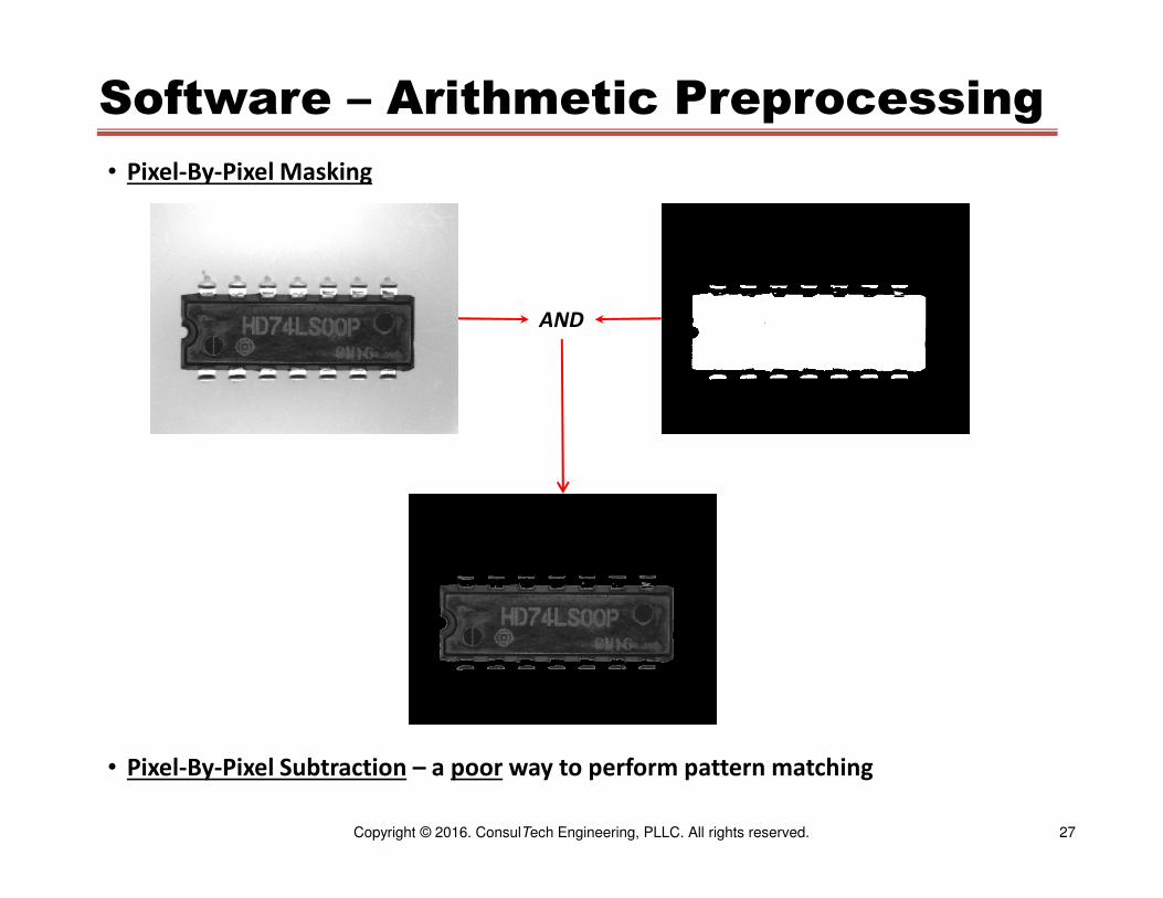
Software – Arithmetic Preprocessing
• Pixel-By-Pixel Masking
• Pixel-By-Pixel Subtraction – a poor way to perform pattern matching
AND

28Copyright © 2016. ConsulTech Engineering, PLLC. All rights reserved.
Software – Arithmetic Preprocessing
• Pixel-By-Pixel Adding
∑
Red
Component Blue
ComponentGreen Component
Computed
Gray Image
Original RGB
Color Image
29Copyright © 2016. ConsulTech Engineering, PLLC. All rights reserved.
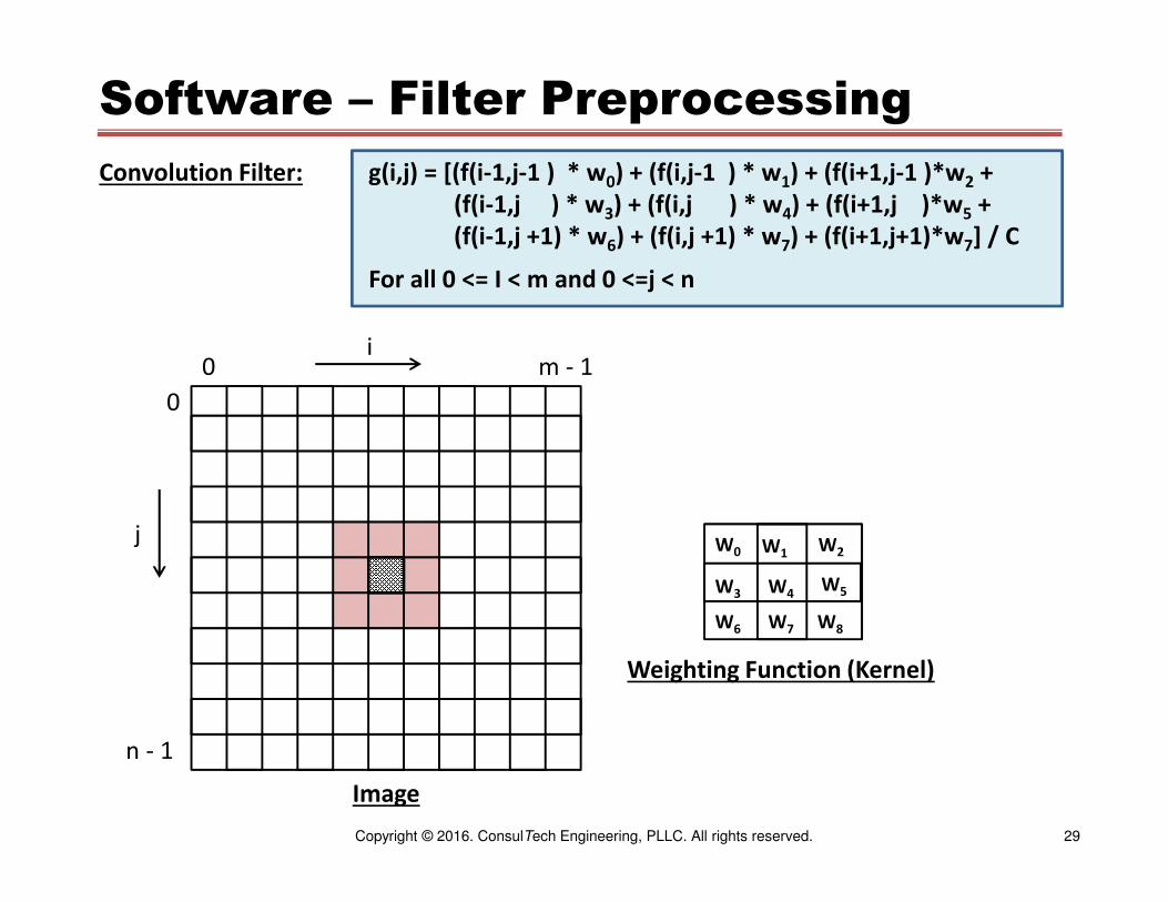
Software – Filter Preprocessing
0 m - 1
0
n - 1
i
j W0 W1 W2
W3 W4W5
W6 W7 W8
g(i,j) = [(f(i-1,j-1 ) * w0) + (f(i,j-1 ) * w1) + (f(i+1,j-1 )*w2 +
(f(i-1,j ) * w3) + (f(i,j ) * w4) + (f(i+1,j )*w5 +
(f(i-1,j +1) * w6) + (f(i,j +1) * w7) + (f(i+1,j+1)*w7] / C
For all 0 <= I < m and 0 <=j < n
Image
Weighting Function (Kernel)
Convolution Filter:

30Copyright © 2016. ConsulTech Engineering, PLLC. All rights reserved.
Software – Filter Preprocessing
1/9 1/9 1/9
Average
1/9 1/9 1/9
1/9 1/9 1/9
-1 -1 -1
-1 9 -1
-1 -1 -1
Edge
Convolution Filter:
31Copyright © 2016. ConsulTech Engineering, PLLC. All rights reserved.
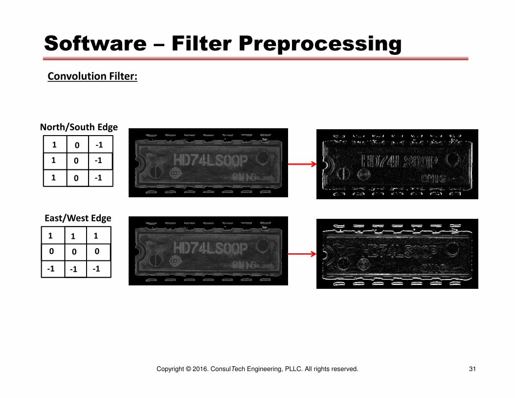
Software – Filter Preprocessing
1 0 -1
1 0 -1
1 0 -1
North/South Edge
1 1 1
0 0 0
-1 -1 -1
East/West Edge
Convolution Filter:
32Copyright © 2016. ConsulTech Engineering, PLLC. All rights reserved.
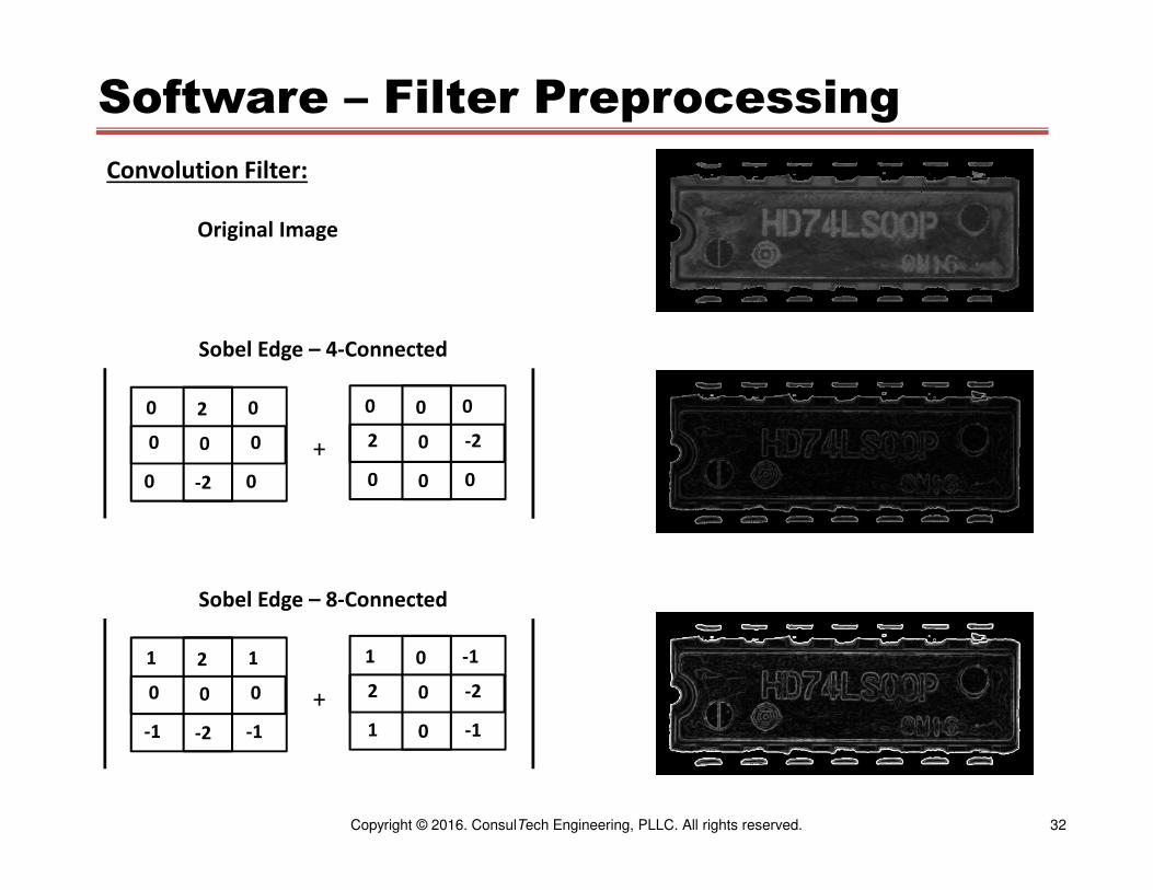
Software – Filter Preprocessing
0 2 0
0 0 0
0 -2 0
Sobel Edge – 4-Connected
0 0 0
2 0 -2
0 0 0
+
Convolution Filter:
1 2 1
0 0 0
-1 -2 -1
Sobel Edge – 8-Connected
1 0 -1
2 0 -2
1 0 -1
+
Original Image

33Copyright © 2016. ConsulTech Engineering, PLLC. All rights reserved.
Software – Filter Preprocessing
X
X 0 X
X
Binary Morphology:
Dilate
X X X
X 0 X
X X X
4-Connected 8-Connected
Change center pixel from 0 to 1 if any X = 1
X
X 1 X
X
Erode
X X X
X 1 X
X X X
4-Connected 8-Connected
Change center pixel from 1 to 0 if any X = 0
Thresholded Image Dilate 3 Iterations Erode 3 Iterations

34Copyright © 2016. ConsulTech Engineering, PLLC. All rights reserved.
Software – Filter Preprocessing
Binary Morphology:
Open – Multiple erode
operations followed by
multiple dilate operations
Erode 1 iteration
(8-Connected)
Dilate 1 iteration
(4-Connected)
Close – Multiple dilate
operations followed by
multiple erode operations
Dilate 27 iterations
(8-Connected)
Erode 27 iterations
(8-Connected)

35Copyright © 2016. ConsulTech Engineering, PLLC. All rights reserved.
Software – Geometric Transformation
Translation
Requires one fiducial point
g(x, y) = f( x + tx , y + ty )
+ Magnification
Requires two fiducial points
g(x, y) = f( mx (x + x’), my (y + y’) )
+ Rotation
Requires three fiducial points
g(x,y) = a • x2 + b • y2 + c • x • y + d • x + e • y + f
Align 3
Features
Such as
Corners
Align 1 Feature
Such as Center-
of-Mass
Align 2
Features
Such as
Corners
36Copyright © 2016. ConsulTech Engineering, PLLC. All rights reserved.
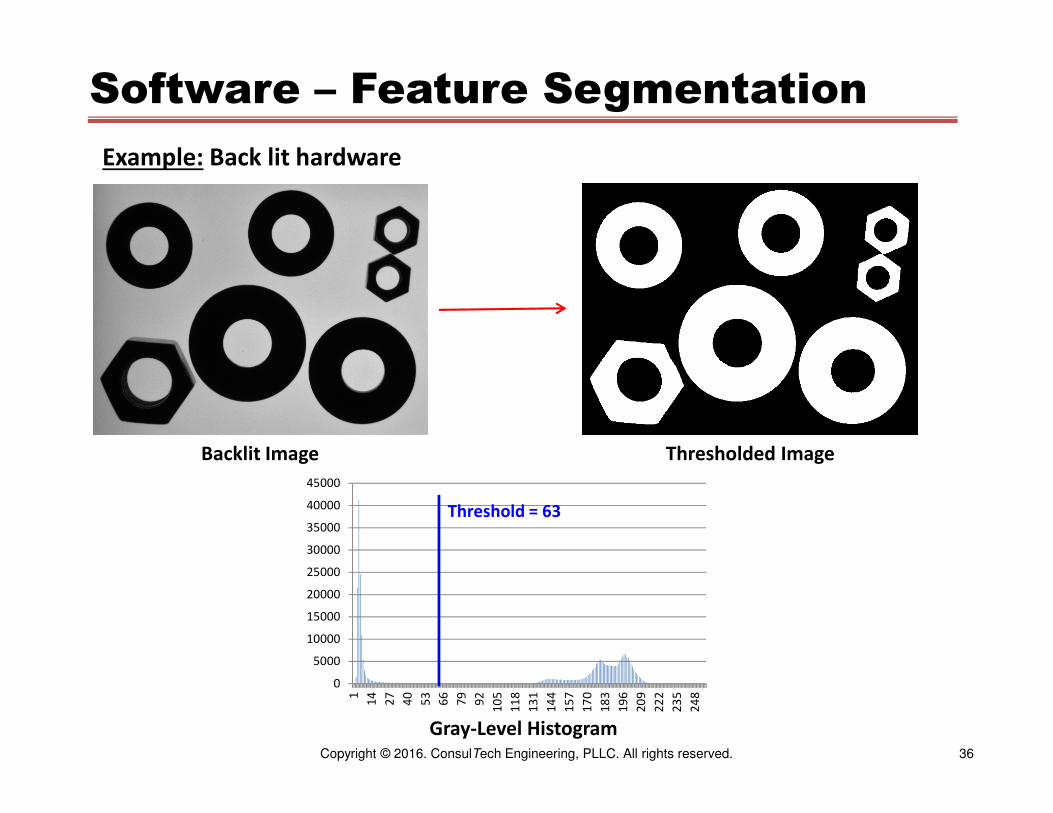
Software – Feature Segmentation
Example: Back lit hardware
Backlit Image
0
5000
10000
15000
20000
25000
30000
35000
40000
45000
1
14
27
40
53
66
79
92
10
5
11
8
13
1
14
4
15
7
17
0
18
3
19
6
20
9
22
2
23
5
24
8
Gray-Level Histogram
Thresholded Image
Threshold = 63

37Copyright © 2016. ConsulTech Engineering, PLLC. All rights reserved.
Software – Feature Segmentation
Example: Vials are filled with a liquid. Are they filled the proper amount?
Illumination: Back lighting
Camera: 640 x 480 area scan
Optics: 15 mm c-mount lens
Not Filled Partially Filled Properly Filled

38Copyright © 2016. ConsulTech Engineering, PLLC. All rights reserved.
Software – Feature Segmentation
Properly Filled Example
Invert Gray
Levels
Sobel Edge
Detection
East-West
Directional
Edge
Detection

39Copyright © 2016. ConsulTech Engineering, PLLC. All rights reserved.
Software – Feature Segmentation
Invert Gray
Levels
Sobel Edge
Detection
East-West
Directional
Edge
Detection
Partially Filled Example

40Copyright © 2016. ConsulTech Engineering, PLLC. All rights reserved.
Software – Feature Segmentation
Invert Gray
Levels
Sobel Edge
Detection
East-West
Directional
Edge
Detection
Empty Example

41Copyright © 2016. ConsulTech Engineering, PLLC. All rights reserved.
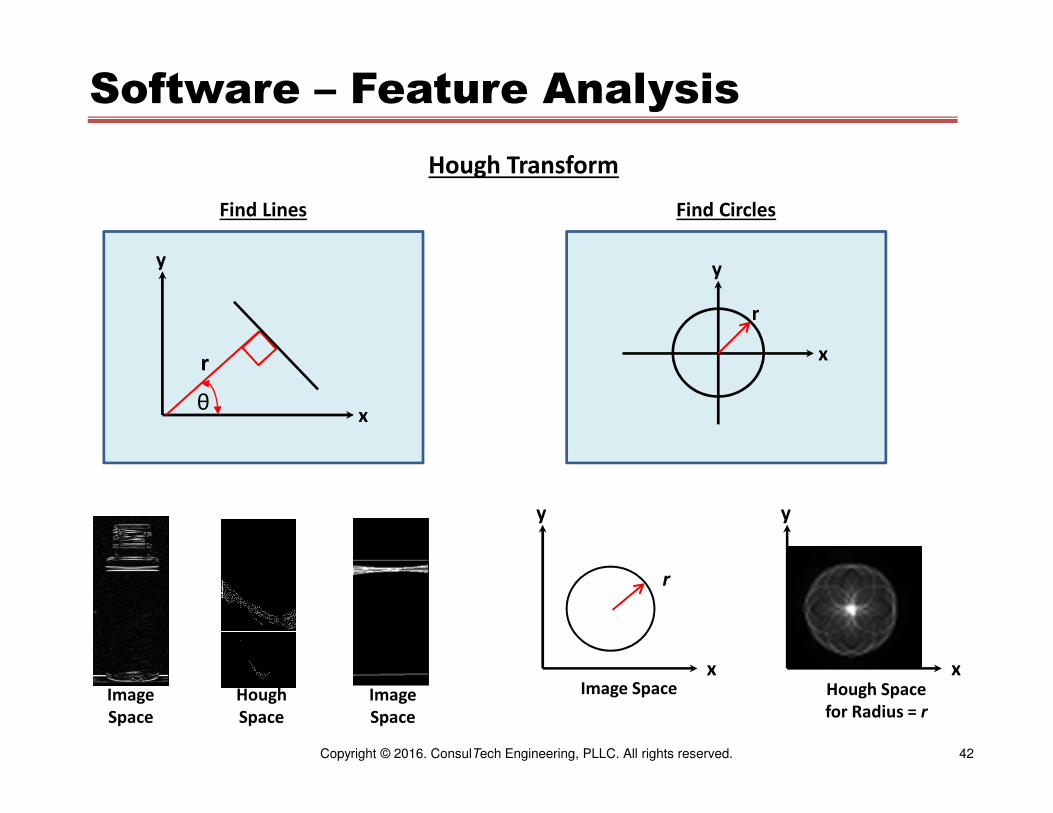
Software – Feature Analysis
Hough Transform
Original
Image
Space
Parameter
Space
Thresholded
Parameter
Space
Image
Space
Step Find Lines Find CirclesEquation x cos θ + y sin θ = r x2 + y2 = r2
Parameter Space
r, θ x, y for each r (one plane for each r)
Parameter Space
1. Add the gray-level of each pixel in the image space (x, y) where
r = �� − ��and
θ = cos-1(�/�)
to the parameter space at coordinates r, θ
2. Threshold parameter space
1. Add the gray-level of each pixel in the image space whose x, y coordinates solve the above equation for the selected value of r to the parameter space at coordinates x, y
2. Threshold the parameter space
Image Space Draw lines in the image space for all points in parameter space (r, θ,) whose
values exceed the threshold where
x = cos(r) and y = sin(r)
Draw circles in the image space with centers at (x,y) and with radius r for all points in parameter space that exceed the threshold
42Copyright © 2016. ConsulTech Engineering, PLLC. All rights reserved.
Software – Feature Analysis
Hough Transform
r
θx
y
x
y
r
Find Lines Find Circles
x
y
x
y
r
Image Space Hough Space
for Radius = rImage
Space
Image
Space
Hough
Space
43Copyright © 2016. ConsulTech Engineering, PLLC. All rights reserved.
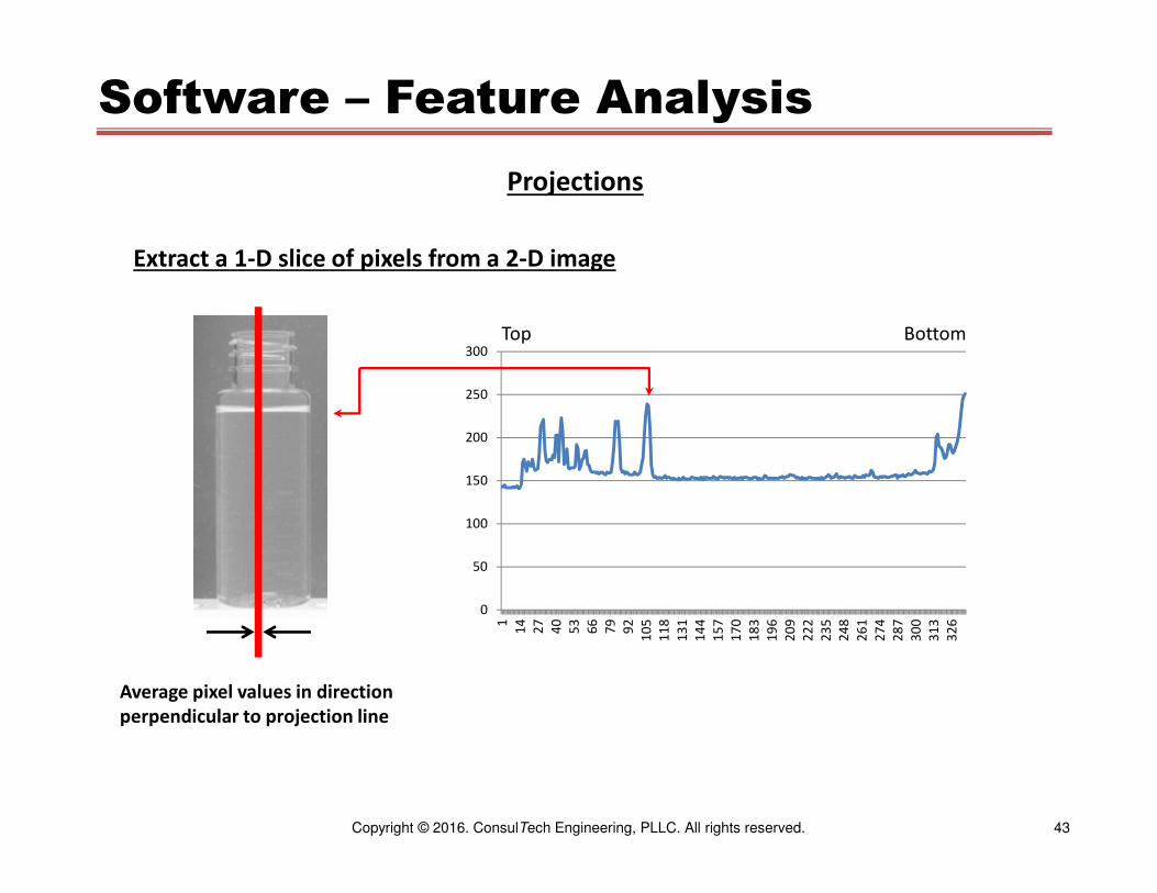
Software – Feature Analysis
Projections
Extract a 1-D slice of pixels from a 2-D image
Average pixel values in direction
perpendicular to projection line
0
50
100
150
200
250
300
1
14
27
40
53
66
79
92
10
5
11
8
13
1
14
4
15
7
17
0
18
3
19
6
20
9
22
2
23
5
24
8
26
1
27
4
28
7
30
0
31
3
32
6
Top Bottom
44Copyright © 2016. ConsulTech Engineering, PLLC. All rights reserved.
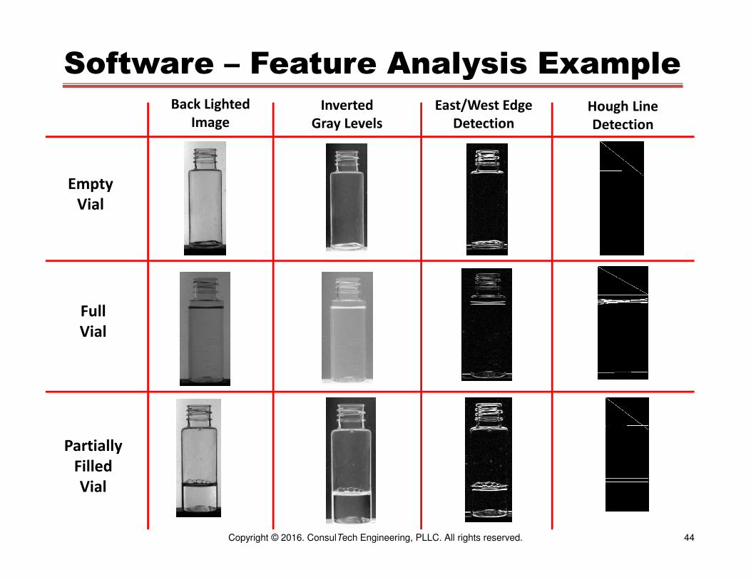
Software – Feature Analysis ExampleBack Lighted
Image
Inverted
Gray Levels
East/West Edge
DetectionHough Line
Detection
Empty
Vial
Full
Vial
Partially
Filled
Vial
45Copyright © 2016. ConsulTech Engineering, PLLC. All rights reserved.
0
50
100
150
200
250
300
1
19
37
55
73
91
10
9
12
7
14
5
16
3
18
1
19
9
21
7
23
5
25
3
27
1
28
9
30
7
32
5
0
50
100
150
200
250
300
1
18
35
52
69
86
10
3
12
0
13
7
15
4
17
1
18
8
20
5
22
2
23
9
25
6
27
3
29
0
30
7
32
4
0
50
100
150
200
250
300
1
19
37
55
73
91
10
9
12
7
14
5
16
3
18
1
19
9
21
7
23
5
25
3
27
1
28
9
30
7
32
5
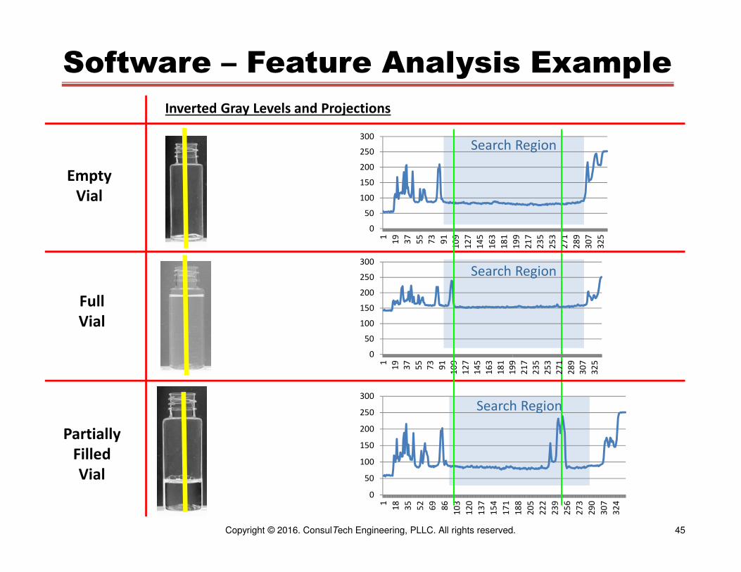
Software – Feature Analysis Example
Inverted Gray Levels and Projections
Empty
Vial
Full
Vial
Partially
Filled
Vial
Search Region
Search Region
Search Region
46Copyright © 2016. ConsulTech Engineering, PLLC. All rights reserved.
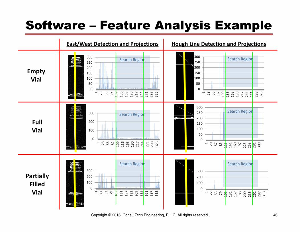
Software – Feature Analysis Example
East/West Detection and Projections Hough Line Detection and Projections
Empty
Vial
Full
Vial
Partially
Filled
Vial
0
50
100
150
200
250
300
1
28
55
82
10
9
13
6
16
3
19
0
21
7
24
4
27
1
29
8
32
5
0
50
100
150
200
250
300
1
28
55
82
10
9
13
6
16
3
19
0
21
7
24
4
27
1
29
8
32
5
0
100
200
300
1
28
55
82
10
9
13
6
16
3
19
0
21
7
24
4
27
1
29
8
32
5
0
50
100
150
200
250
300
1
29
57
85
11
3
14
1
16
9
19
7
22
5
25
3
28
1
30
9
0
100
200
300
1
27
53
79
10
5
13
1
15
7
18
3
20
9
23
5
26
1
28
7
31
3
0
100
200
300
1
27
53
79
10
5
13
1
15
7
18
3
20
9
23
5
26
1
28
7
31
3
Search Region
Search Region
Search Region Search Region
Search Region
Search Region

47Copyright © 2016. ConsulTech Engineering, PLLC. All rights reserved.
Software – Feature Analysis
Blob (Binary Large Object) Analysis:
1. Performed on binary image
2. Find first “white” pixel
3. Recursively grow blob in all directions from the white pixel
4. Find next white pixel that is not part of a blob
5. Repeat steps 3 and 4 until entire image is analyzed
6. Compute metrics:
a. Ellipse Perimeter
b. Ellipse Area
c. Ellipse Major and Minor Radii
d. Ellipse Rotation
e. Enclosing Rectangle
f. Circularity = perimeter2 / (4π area)

48Copyright © 2016. ConsulTech Engineering, PLLC. All rights reserved.
Software – Feature Analysis
Blob Analysis:
Backlit Image Threshold Open
Blob Analysis Blob Analysis
0
10000
20000
30000
40000
50000
1
21
41
61
81
10
1
12
1
14
1
16
1
18
1
20
1
22
1
24
1
Backlit Image Histogram
Threshold = 63

49Copyright © 2016. ConsulTech Engineering, PLLC. All rights reserved.
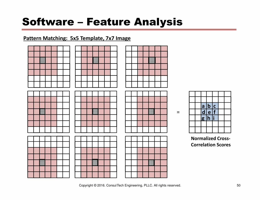
Software – Feature Analysis
Pattern Matching:
1. Find a segment of a search image, f( i, j ), that matches the contents of a template
image, t( i, j ) where the template image is smaller than the search image.
2. Uses:
o Match fiducial points or segments for image alignment
o Presence/Absence analysis
3. Operation:
a. Slide template over search image and calculate Normalized Cross-Correlation at each
increment of sliding (m, n)
b. Find peak value of Normalized Cross-Correlation optionally by fitting a curve (bi-linear, bi-
quadratic, …) to the NCC map near the peak value
∑ [ ( f( i, j ) – f ) * ( t( i + m, j + n ) – t ) ]i,j
NCC =
∑ ( f( i, j ) – f ) 2 * ∑ ( t( i + m, j + n ) – t ) 2
i,j i,j
for: mmin < m < mmax and nmin < n < nmax
where: 0 < NCC < 1.0
50Copyright © 2016. ConsulTech Engineering, PLLC. All rights reserved.
Software – Feature Analysis
Pattern Matching: 5x5 Template, 7x7 Image
=
Normalized Cross-
Correlation Scores
a b cd e fg h i
51Copyright © 2016. ConsulTech Engineering, PLLC. All rights reserved.
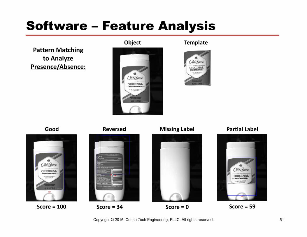
Software – Feature Analysis
Pattern Matching
to Analyze
Presence/Absence:
Score = 34 Score = 0Score = 100
Object
Good Reversed
Template
Missing Label
Score = 59
Partial Label

52Copyright © 2016. ConsulTech Engineering, PLLC. All rights reserved.
Software – Feature Analysis
Pattern Matching
to Analyze
Presence/Absence:
Object Template
Score = 90Score = 85 Score = 76
Dark ImageHistogram
Equalized
Score = 57
Label Misplaced Object Rotated
53Copyright © 2016. ConsulTech Engineering, PLLC. All rights reserved.
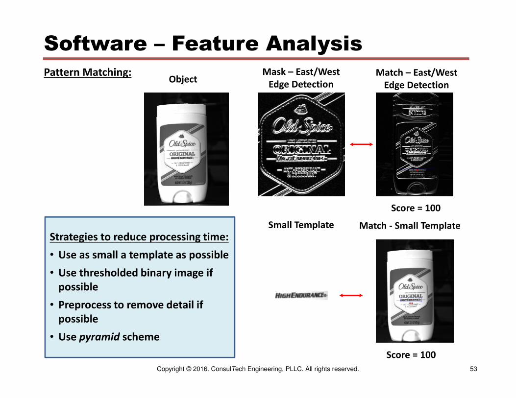
Software – Feature Analysis
Pattern Matching:
Score = 100
Mask – East/West
Edge DetectionMatch – East/West
Edge Detection
Small Template
Score = 100
Match - Small Template
Object
Strategies to reduce processing time:
• Use as small a template as possible
• Use thresholded binary image if
possible
• Preprocess to remove detail if
possible
• Use pyramid scheme

54Copyright © 2016. ConsulTech Engineering, PLLC. All rights reserved.
Example – Semiconductor Wafers
• Locate wafers as they are extracted
from an oven.
• Determine if any wafers are broken.
• Send location of unbroken wafers to
robot for extraction from the rack.
• Report any broken wafers.

55Copyright © 2016. ConsulTech Engineering, PLLC. All rights reserved.
Example – Semiconductor Wafers
• Goal – Illuminate and image only the wafer edges
• Illumination – Back lighting
• Camera – Line Scan

56Copyright © 2016. ConsulTech Engineering, PLLC. All rights reserved.
Example – Semiconductor Wafers
Positive Inspection
Negative Inspection
• Capture line scans at fixed time
intervals
• Threshold each line
• Analyze multiple vertical profiles
across the image width to locate
wafers
• Analyze Profiles:
o Calibrate dimensions from a priori
information about wafer spacing
o Determine wafer condition
o Determine wafer location
• When the entire rack has been
extracted, send coordinates of
undamaged wafers to robot for
extraction

57Copyright © 2016. ConsulTech Engineering, PLLC. All rights reserved.
Example
TSA Training System
Simulated Threat Weapons
Challenges:
• 1980’s time frame
• Compensate for moving belt
• Processing speed
• Threat weapon must be totally
enclosed by luggage
58Copyright © 2016. ConsulTech Engineering, PLLC. All rights reserved.
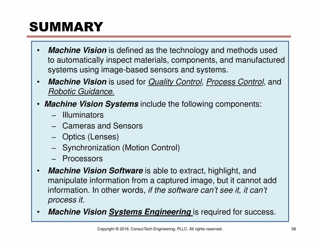
SUMMARY
• Machine Vision is defined as the technology and methods used to automatically inspect materials, components, and manufactured systems using image-based sensors and systems.
• Machine Vision is used for Quality Control, Process Control, and Robotic Guidance.
• Machine Vision Systems include the following components:
− Illuminators
− Cameras and Sensors
− Optics (Lenses)
− Synchronization (Motion Control)
− Processors
• Machine Vision Software is able to extract, highlight, and manipulate information from a captured image, but it cannot add information. In other words, if the software can’t see it, it can’t process it.
• Machine Vision Systems Engineering is required for success.
59Copyright © 2016. ConsulTech Engineering, PLLC. All rights reserved.
QUESTIONS?
?

60Copyright © 2016. ConsulTech Engineering, PLLC. All rights reserved.
REVIEW QUESTIONS and ANSWERS
1. What is Machine Vision?Machine Vision is the technology and methods used to automatically inspect
materials, components, and manufactured systems using image-based sensors and
systems.
2. What are the uses of Machine Vision?Machine Vision is used for Quality Control, Process Control, and Robotic Guidance.
3. What are the components of a Machine Vision System?A Machine Vision System includes illuminators, sensors (cameras), optics (lenses),
synchronizers (motion controllers and/or encoders), processors, and software.
4. Name some of the Machine Vision processing platforms?PC, smart cameras, GPU, FPGA, Systems on a Chip (SoC).
5. What are the five Machine Vision processing steps?1. Image Acquisition
2. Image Pre-Processing
3. Feature Segmentation
4. Feature Analysis
5. Reporting
61Copyright © 2016. ConsulTech Engineering, PLLC. All rights reserved.
Thank You For Attending
Automated Inspection
With
Machine VisionPart 3
Stanley N. Hack, D.Sc., PE
www.consultechusa.com
November 7, 2016