ni vision builder for automated inspection tutorial ... · ni vision builder for automated...
TRANSCRIPT
NI VisionNI Vision Builder for Automated Inspection Tutorial
NI Vision Builder for Automated Inspection Tutorial
August 2013373379L-01

Support
Worldwide Technical Support and Product Informationni.com
Worldwide Offices
Visit ni.com/niglobal to access the branch office websites, which provide up-to-date contact information, support phone numbers, email addresses, and current events.
National Instruments Corporate Headquarters
11500 North Mopac Expressway Austin, Texas 78759-3504 USA Tel: 512 683 0100
For further support information, refer to the Technical Support and Professional Services appendix. To comment on National Instruments documentation, refer to the National Instruments website at ni.com/info and enter the Info Code feedback.
© 2002–2013 National Instruments. All rights reserved.
Important Information
WarrantyNI devices are warranted against defects in materials and workmanship for a period of one year from the invoice date, as evidenced by receipts or other documentation. National Instruments will, at its option, repair or replace equipment that proves to be defective during the warranty period. This warranty includes parts and labor. The media on which you receive National Instruments software are warranted not to fail to execute programming instructions, due to defects in materials and workmanship, for a period of 90 days from the invoice date, as evidenced by receipts or other documentation. National Instruments will, at its option, repair or replace software media that do not execute programming instructions if National Instruments receives notice of such defects during the warranty period. National Instruments does not warrant that the operation of the software shall be uninterrupted or error free.A Return Material Authorization (RMA) number must be obtained from the factory and clearly marked on the outside of the package before any equipment will be accepted for warranty work. National Instruments will pay the shipping costs of returning to the owner parts which are covered by warranty.National Instruments believes that the information in this document is accurate. The document has been carefully reviewed for technical accuracy. In the event that technical or typographical errors exist, National Instruments reserves the right to make changes to subsequent editions of this document without prior notice to holders of this edition. The reader should consult National Instruments if errors are suspected. In no event shall National Instruments be liable for any damages arising out of or related to this document or the information contained in it.EXCEPT AS SPECIFIED HEREIN, NATIONAL INSTRUMENTS MAKES NO WARRANTIES, EXPRESS OR IMPLIED, AND SPECIFICALLY DISCLAIMS ANY WARRANTY OF MERCHANTABILITY OR FITNESS FOR A PARTICULAR PURPOSE. CUSTOMER’S RIGHT TO RECOVER DAMAGES CAUSED BY FAULT OR NEGLIGENCE ON THE PART OF NATIONAL INSTRUMENTS SHALL BE LIMITED TO THE AMOUNT THERETOFORE PAID BY THE CUSTOMER. NATIONAL INSTRUMENTS WILL NOT BE LIABLE FOR DAMAGES RESULTING FROM LOSS OF DATA, PROFITS, USE OF PRODUCTS, OR INCIDENTAL OR CONSEQUENTIAL DAMAGES, EVEN IF ADVISED OF THE POSSIBILITY THEREOF. This limitation of the liability of National Instruments will apply regardless of the form of action, whether in contract or tort, including negligence. Any action against National Instruments must be brought within one year after the cause of action accrues. National Instruments shall not be liable for any delay in performance due to causes beyond its reasonable control. The warranty provided herein does not cover damages, defects, malfunctions, or service failures caused by owner’s failure to follow the National Instruments installation, operation, or maintenance instructions; owner’s modification of the product; owner’s abuse, misuse, or negligent acts; and power failure or surges, fire, flood, accident, actions of third parties, or other events outside reasonable control.CopyrightUnder the copyright laws, this publication may not be reproduced or transmitted in any form, electronic or mechanical, including photocopying, recording, storing in an information retrieval system, or translating, in whole or in part, without the prior written consent of National Instruments Corporation.National Instruments respects the intellectual property of others, and we ask our users to do the same. NI software is protected by copyright and other intellectual property laws. Where NI software may be used to reproduce software or other materials belonging to others, you may use NI software only to reproduce materials that you may reproduce in accordance with the terms of any applicable license or other legal restriction.End-User License Agreements and Third-Party Legal NoticesYou can find end-user license agreements (EULAs) and third-party legal notices in the following locations:• Notices are located in the <National Instruments>\_Legal Information and <National Instruments>
directories.• EULAs are located in the <National Instruments>\Shared\MDF\Legal\license directory.• Review <National Instruments>\_Legal Information.txt for more information on including legal information
in installers built with NI products.TrademarksRefer to the NI Trademarks and Logo Guidelines at ni.com/trademarks for more information on National Instruments trademarks.ARM, Keil, and µVision are trademarks or registered of ARM Ltd or its subsidiaries.LEGO, the LEGO logo, WEDO, and MINDSTORMS are trademarks of the LEGO Group. ©2013 The LEGO Group.TETRIX by Pitsco is a trademark of Pitsco, Inc.©2013FIELDBUS FOUNDATION™ and FOUNDATION™ are trademarks of the Fieldbus Foundation.EtherCAT® is a registered trademark of and licensed by Beckhoff Automation GmbH.CANopen® is a registered Community Trademark of CAN in Automation e.V.DeviceNet™ and EtherNet/IP™ are trademarks of ODVA.Go!, SensorDAQ, and Vernier are registered trademarks of Vernier Software & Technology. Vernier Software & Technology and vernier.com are trademarks or trade dress.Xilinx is the registered trademark of Xilinx, Inc.Taptite and Trilobular are registered trademarks of Research Engineering & Manufacturing Inc.FireWire® is the registered trademark of Apple Inc.Linux® is the registered trademark of Linus Torvalds in the U.S. and other countries.
Handle Graphics®, MATLAB®, Real-Time Workshop®, Simulink®, Stateflow®, and xPC TargetBox® are registered trademarks, and TargetBox™ and Target Language Compiler™ are trademarks of The MathWorks, Inc.Tektronix®, Tek, and Tektronix, Enabling Technology are registered trademarks of Tektronix, Inc.The Bluetooth® word mark is a registered trademark owned by the Bluetooth SIG, Inc.The ExpressCard™ word mark and logos are owned by PCMCIA and any use of such marks by National Instruments is under license.The mark LabWindows is used under a license from Microsoft Corporation. Windows is a registered trademark of Microsoft Corporation in the United States and other countries.Other product and company names mentioned herein are trademarks or trade names of their respective companies.Members of the National Instruments Alliance Partner Program are business entities independent from National Instruments and have no agency, partnership, or joint-venture relationship with National Instruments.PatentsFor patents covering National Instruments products/technology, refer to the appropriate location: Help»Patents in your software, the patents.txt file on your media, or the National Instruments Patent Notice at ni.com/patents.Export Compliance InformationRefer to the Export Compliance Information at ni.com/legal/export-compliance for the National Instruments global trade compliance policy and how to obtain relevant HTS codes, ECCNs, and other import/export data.WARNING REGARDING USE OF NATIONAL INSTRUMENTS PRODUCTS(1) NATIONAL INSTRUMENTS PRODUCTS ARE NOT DESIGNED WITH COMPONENTS AND TESTING FOR A LEVEL OF RELIABILITY SUITABLE FOR USE IN OR IN CONNECTION WITH SURGICAL IMPLANTS OR AS CRITICAL COMPONENTS IN ANY LIFE SUPPORT SYSTEMS WHOSE FAILURE TO PERFORM CAN REASONABLY BE EXPECTED TO CAUSE SIGNIFICANT INJURY TO A HUMAN.(2) IN ANY APPLICATION, INCLUDING THE ABOVE, RELIABILITY OF OPERATION OF THE SOFTWARE PRODUCTS CAN BE IMPAIRED BY ADVERSE FACTORS, INCLUDING BUT NOT LIMITED TO FLUCTUATIONS IN ELECTRICAL POWER SUPPLY, COMPUTER HARDWARE MALFUNCTIONS, COMPUTER OPERATING SYSTEM SOFTWARE FITNESS, FITNESS OF COMPILERS AND DEVELOPMENT SOFTWARE USED TO DEVELOP AN APPLICATION, INSTALLATION ERRORS, SOFTWARE AND HARDWARE COMPATIBILITY PROBLEMS, MALFUNCTIONS OR FAILURES OF ELECTRONIC MONITORING OR CONTROL DEVICES, TRANSIENT FAILURES OF ELECTRONIC SYSTEMS (HARDWARE AND/OR SOFTWARE), UNANTICIPATED USES OR MISUSES, OR ERRORS ON THE PART OF THE USER OR APPLICATIONS DESIGNER (ADVERSE FACTORS SUCH AS THESE ARE HEREAFTER COLLECTIVELY TERMED “SYSTEM FAILURES”). ANY APPLICATION WHERE A SYSTEM FAILURE WOULD CREATE A RISK OF HARM TO PROPERTY OR PERSONS (INCLUDING THE RISK OF BODILY INJURY AND DEATH) SHOULD NOT BE RELIANT SOLELY UPON ONE FORM OF ELECTRONIC SYSTEM DUE TO THE RISK OF SYSTEM FAILURE. TO AVOID DAMAGE, INJURY, OR DEATH, THE USER OR APPLICATION DESIGNER MUST TAKE REASONABLY PRUDENT STEPS TO PROTECT AGAINST SYSTEM FAILURES, INCLUDING BUT NOT LIMITED TO BACK-UP OR SHUT DOWN MECHANISMS. BECAUSE EACH END-USER SYSTEM IS CUSTOMIZED AND DIFFERS FROM NATIONAL INSTRUMENTS' TESTING PLATFORMS AND BECAUSE A USER OR APPLICATION DESIGNER MAY USE NATIONAL INSTRUMENTS PRODUCTS IN COMBINATION WITH OTHER PRODUCTS IN A MANNER NOT EVALUATED OR CONTEMPLATED BY NATIONAL INSTRUMENTS, THE USER OR APPLICATION DESIGNER IS ULTIMATELY RESPONSIBLE FOR VERIFYING AND VALIDATING THE SUITABILITY OF NATIONAL INSTRUMENTS PRODUCTS WHENEVER NATIONAL INSTRUMENTS PRODUCTS ARE INCORPORATED IN A SYSTEM OR APPLICATION, INCLUDING, WITHOUT LIMITATION, THE APPROPRIATE DESIGN, PROCESS AND SAFETY LEVEL OF SUCH SYSTEM OR APPLICATION.
© National Instruments | v
Contents
About This ManualRelated Documentation .................................................................................................... x
Chapter 1Introduction to Vision Builder AIVision Builder AI Configuration Interface....................................................................... 1-4
Elements of the Configuration Interface .................................................................. 1-4Inspection State Diagram.......................................................................................... 1-6
Vision Builder AI Inspection Interface ............................................................................ 1-7Running an Inspection ...................................................................................................... 1-7
Configuration Interface............................................................................................. 1-8Inspection Interface .................................................................................................. 1-9
Chapter 2Checking for the Presence of a PartCreating a New Inspection ............................................................................................... 2-1Acquiring Inspection Images............................................................................................ 2-1Defining a Feature on which to Base a Coordinate System ............................................. 2-2Setting a Coordinate System............................................................................................. 2-5Checking for the Cap Using Measure Intensity................................................................ 2-6Setting the Inspection Status............................................................................................. 2-8Testing the Inspection....................................................................................................... 2-9Saving the Inspection........................................................................................................ 2-9
Chapter 3Inspecting Objects for Correct MeasurementsCreating a New Inspection ............................................................................................... 3-1Acquiring and Calibrating Inspection Images .................................................................. 3-1Locating Features to Measure........................................................................................... 3-4Measuring Parts of the Gasket.......................................................................................... 3-7Setting the Inspection Status............................................................................................. 3-8Testing the Inspection....................................................................................................... 3-9Saving the Inspection........................................................................................................ 3-9
Chapter 4Inspecting for Multiple Correct Instances of an ObjectCreating a New Inspection ............................................................................................... 4-1Acquiring Inspection Images............................................................................................ 4-1Defining a Feature on which to Base a Coordinate System ............................................. 4-2Setting a Coordinate System............................................................................................. 4-4Measuring the Separation between Connectors................................................................ 4-4
Contents
vi | ni.com
Inspecting the Fuse Conductor .........................................................................................4-6Making Logical PASS/FAIL Decisions ...........................................................................4-9Setting the Inspection Status.............................................................................................4-10Testing the Inspection .......................................................................................................4-11Saving the Inspection........................................................................................................4-12
Chapter 5Inspecting an Object that Spans Two Image FramesCreating a New Inspection................................................................................................5-1Acquiring Inspection Images from Two Cameras ............................................................5-1
Acquiring and Calibrating the Image of the Left Edge ............................................5-2Acquiring and Calibrating the Image of the Right Edge ..........................................5-4
Locating the Right Edge of the Part..................................................................................5-7Switching Images..............................................................................................................5-9Locating the Left Edge of the Part....................................................................................5-9Calculating the Width of the Part .....................................................................................5-11
Setting Calculator Step Inputs and Outputs ..............................................................5-11Adding Operators and Constants ..............................................................................5-13Connecting the Equation Elements...........................................................................5-14Making Logical PASS/FAIL Decisions with the Calculator Step............................5-16
Setting the Inspection Status.............................................................................................5-17Testing the Inspection .......................................................................................................5-18Saving the Inspection........................................................................................................5-18
Chapter 6Branching and Decision MakingCreating a New Inspection................................................................................................6-1Creating the Inspection State Diagram .............................................................................6-1Acquiring Inspection Images ............................................................................................6-5Checking for a Spray Bottle in the Image.........................................................................6-6Checking for the Cap Using the Caliper ...........................................................................6-7Setting the Inspection Status.............................................................................................6-9Creating Custom Overlays for Inspection ........................................................................6-9Configuring State Transitions ...........................................................................................6-12Testing the Inspection .......................................................................................................6-13Saving the Inspection........................................................................................................6-14
Chapter 7Looping and VariablesCreating a New Inspection................................................................................................7-1Creating the Inspection State Diagram .............................................................................7-1Creating a Variable ...........................................................................................................7-5Acquiring Inspection Images ............................................................................................7-6Finding Pin Edges.............................................................................................................7-7
NI Vision Builder for Automated Inspection Tutorial
© National Instruments | vii
Initializing the Variable .................................................................................................... 7-8Indexing Measurements in a Result Array ....................................................................... 7-8Setting a Coordinate System............................................................................................. 7-9Checking the Pin Gap ....................................................................................................... 7-9Updating the Variable....................................................................................................... 7-10Identifying Failed Pins...................................................................................................... 7-11Setting the Inspection Status............................................................................................. 7-12Displaying the Current Inspection Image......................................................................... 7-12Configuring State Transitions........................................................................................... 7-13Testing the Inspection....................................................................................................... 7-14Saving the Inspection........................................................................................................ 7-15
Appendix ATechnical Support and Professional Services
Glossary

© National Instruments | ix
About This Manual
This manual contains many techniques for using NI Vision Builder for Automated Inspection (Vision Builder AI) to solve visual inspection tasks including inspection, gauging, part presence, guidance, and counting.
Follow the instructions in this manual to familiarize yourself with Vision Builder AI and perform common inspection tasks.
This manual contains the following chapters:• Chapter 1, Introduction to Vision Builder AI, introduces the Vision Builder AI environment
and describes how to run an inspection.• Chapter 2, Checking for the Presence of a Part, introduces the Match Pattern, Measure
Intensity, and Set Coordinate System steps. Follow the instructions in this chapter to create an inspection that checks for the presence of a spray bottle cap regardless of the bottle position in the inspection images.
• Chapter 3, Inspecting Objects for Correct Measurements, introduces image calibration, and the Detect Objects and Geometry steps. Follow the instructions in this chapter to create an inspection that measures the distance between holes in a gasket to verify that the gasket conforms to manufacturing specifications.
• Chapter 4, Inspecting for Multiple Correct Instances of an Object, introduces the Find Straight Edge, Caliper, and Decision Making steps. Follow the instructions in this chapter to create an inspection that measures the distance between the blade connectors of a fuse and checks the integrity of the fuse conductor regardless of the fuse position or whether the fuse is inverted.
• Chapter 5, Inspecting an Object that Spans Two Image Frames, introduces the Select Image and Calculator steps. Follow the instructions in this chapter to create an inspection that measures the width of a wooden plank that spans two images.
• Chapter 6, Branching and Decision Making, introduces the inspection state diagram and the Custom Overlay step. Follow the instructions in this chapter to create an inspection that checks the image for the presence of a spray bottle and, if a bottle is present, transitions to another state to determine if the bottle has a cap. If there is no spray bottle present in the image, the inspection moves on to the next image.
• Chapter 7, Looping and Variables, uses the inspection state diagram to implement a looping inspection and introduces the Set Variable and Array Operator steps. Follow the instructions in this chapter to create an inspection that inspects images of electronic components to determine if the distance between pins on the component is within a predetermined range. If the pin is too close or too far away from an adjacent pin, then the inspection fails. The inspection does not need to check every pin on the microchip before failing the inspection. The inspection fails at the first failed pin.
About This Manual
x | ni.com
Related DocumentationThe following documents contain information that you might find helpful as you read this manual:• NI Vision Builder for Automated Inspection Readme—Contains information about the
minimum system requirements, installation instructions, device support, and known issues for NI Vision Builder for Automated Inspection. The NI Vision Builder for Automated Inspection Readme is available at Start»All Programs»National Instruments»Vision Builder AI»Documentation.
• NI Vision Builder for Automated Inspection: Configuration Help—Contains information about using the Vision Builder AI Configuration interface to create a machine vision application. NI Vision Builder for Automated Inspection: Configuration Help is available by selecting Help»Online Help from the Vision Builder AI Configuration interface.
• NI Vision Builder for Automated Inspection: Inspection Help—Contains information about running applications created using Vision Builder AI in the Vision Builder AI Inspection Interface. NI Vision Builder for Automated Inspection: Inspection Help is available by selecting Help»Online Help from the Vision Builder AI Inspection interface.
• NI Developer Zone—Visit ni.com/zone for the latest example programs, tutorials, technical presentations, and a community area where you can share ideas, questions, and source code with developers around the world.
• NI 17xx Smart Camera User Manual—Describes the electrical and mechanical aspects of the NI 17xx smart camera, troubleshooting guidelines, and information about the LEDs, DIP switches, and connectors on the NI 17xx.
• NI 177x Smart Camera User Manual—Describes the electrical and mechanical aspects of the NI 177x smart camera and information about the LEDs and connectors on the NI 177x.
• NI EVS-1463 User Manual—Describes the electrical and mechanical aspects of the NI EVS-1463 embedded vision system, troubleshooting guidelines, and information about the LEDs, DIP switches, and connectors on the EVS-1463 device.
• NI EVS-1464 User Manual—Describes the electrical and mechanical aspects of the NI EVS-1464 embedded vision system, troubleshooting guidelines, and information about the LEDs, DIP switches, and connectors on the EVS-1464 device.
• NI Smart Camera I/O Accessory User Guide—Describes the features of the NI Smart Camera I/O Accessory, what you need to get started, and the installation and operation of the device.
• NI Vision Concepts Help—Describes the basic concepts of image analysis, image processing, and machine vision. This document also contains in-depth discussions about imaging algorithms for advanced users. The NI Vision Concepts Help is available by selecting Start»All Programs»National Instruments»Vision Builder AI»Documentation»NI Vision Concepts Help from the Start menu.
© National Instruments | 1-1
1Introduction to Vision Builder AI
This chapter introduces the Vision Builder AI environment and describes how to run an inspection.
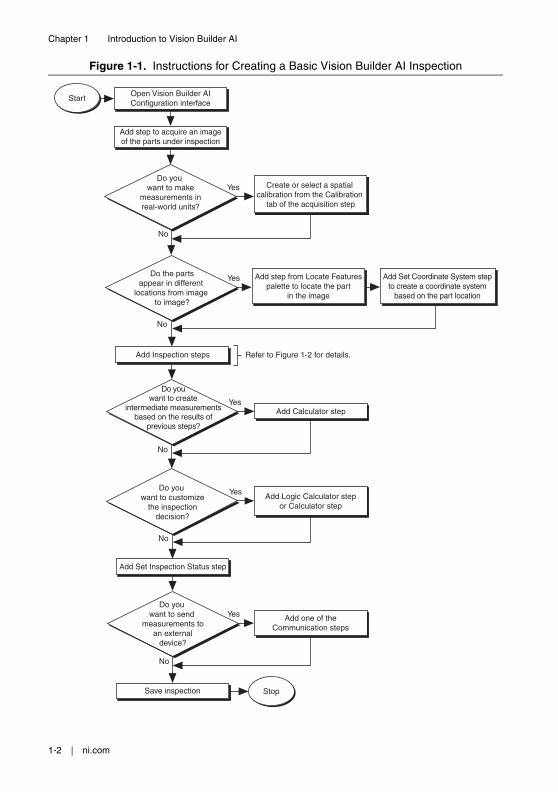
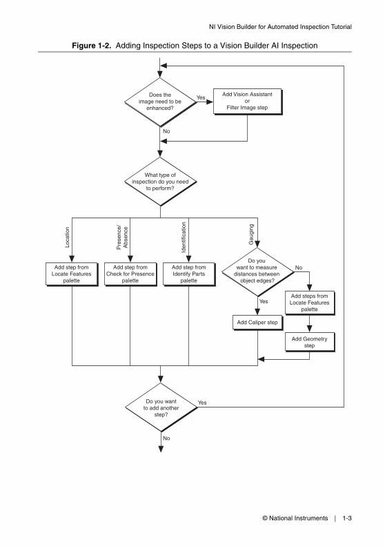
Figures 1-1 and 1-2 show general instructions for creating a Vision Builder AI inspection. Figure 1-1 describes the basic steps for designing a Vision Builder AI inspection. The Add Inspection Steps module of Figure 1-1 is expanded in Figure 1-2.
1-2 | ni.com
Chapter 1 Introduction to Vision Builder AI
Figure 1-1. Instructions for Creating a Basic Vision Builder AI Inspection
Stop
No
Yes
No
YesAdd Calculator step
Yes
No
Refer to Figure 1-2 for details.
Start
Add Set Coordinate System stepto create a coordinate system
based on the part location
No
Yes
Do youwant to create
intermediate measurementsbased on the results of
previous steps?
Add step from Locate Featurespalette to locate the part
in the image
Open Vision Builder AIConfiguration interface
Add step to acquire an imageof the parts under inspection
Do the partsappear in different
locations from image to image?
Add Inspection steps
Save inspection
Add Logic Calculator stepor Calculator step
Do you want to customize
the inspectiondecision?
Do you want to send
measurements toan external
device?
Add one of theCommunication steps
Add Set Inspection Status step
No
YesDo you
want to makemeasurements inreal-world units?
Create or select a spatial calibration from the Calibration
tab of the acquisition step
© National Instruments | 1-3
NI Vision Builder for Automated Inspection Tutorial
Figure 1-2. Adding Inspection Steps to a Vision Builder AI Inspection
Add Caliper step
Add step fromLocate Features
palette.
Yes
No
Does theimage need to be
enhanced?
What type ofinspection do you need
to perform?
Loca
tion
Pre
senc
e/A
bsen
ce
Gau
ging
Iden
tific
atio
n
Add step fromLocate Features
palette
Add step fromCheck for Presence
palette
Add step fromIdentify Parts
palette
Add steps fromLocate Features
palette
Do you want to measure
distances between object edges?
No
Yes
Do you wantto add another
step?
Yes
No
Add Geometrystep
Add Vision Assistantor
Filter Image step
1-4 | ni.com
Chapter 1 Introduction to Vision Builder AI
Vision Builder AI Configuration InterfaceVision Builder AI has two modes of operation: Configuration and Inspection. Use the Configuration interface to configure and test your inspection. Use the Inspection interface to deploy the software and perform online or offline visual inspection.
Complete the following instructions to open the Vision Builder AI Configuration interface.1. Select Start»All Programs»National Instruments»Vision Builder AI to launch Vision
Builder AI.
Note By default, My Computer is selected in the list of targets. When My Computer is selected Vision Builder AI runs on the development computer.
2. On the Vision Builder AI welcome screen, click New Inspection to open the Vision Builder AI Configuration Interface.
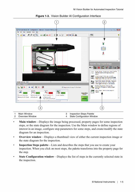
Elements of the Configuration InterfaceFigure 1-3 shows the Vision Builder AI Configuration interface. The Configuration interface contains four areas: Main window, Overview window, Inspection Steps palette, and State Configuration window.
© National Instruments | 1-5
NI Vision Builder for Automated Inspection Tutorial
Figure 1-3. Vision Builder AI Configuration Interface
• Main window—Displays the image being processed, property pages for some inspection steps, or the state diagram for the inspection. Use the Main window to define regions of interest in an image, configure step parameters for some steps, and create/modify the state diagram for an inspection.
• Overview window—Displays a thumbnail view of either the current inspection image or the state diagram for the inspection.
• Inspection Steps palette—Lists and describes the steps that you use to create your inspection. When you click on most steps, the palette transforms into the property page for the step.
• State Configuration window—Displays the list of steps in the currently selected state in the inspection.
1 Main Window2 Overview Window
3 Inspection Steps Palette4 State Configuration Window
2
4 3
1
1-6 | ni.com
Chapter 1 Introduction to Vision Builder AI
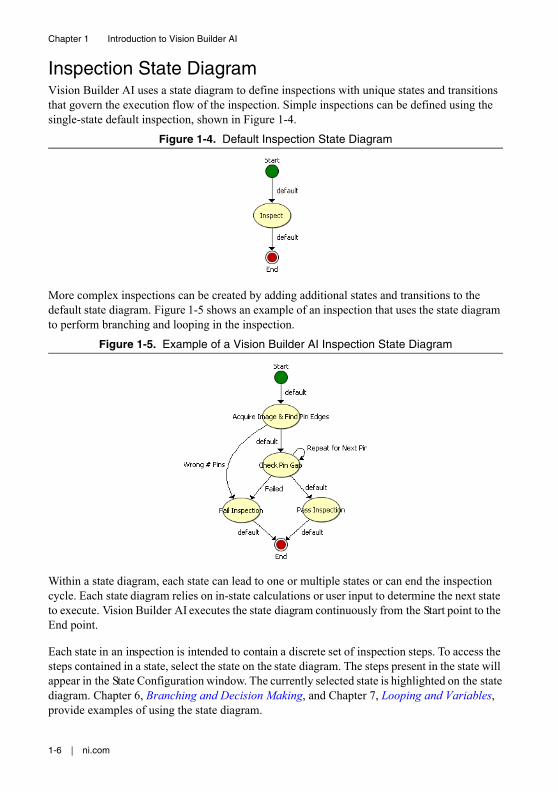
Inspection State DiagramVision Builder AI uses a state diagram to define inspections with unique states and transitions that govern the execution flow of the inspection. Simple inspections can be defined using the single-state default inspection, shown in Figure 1-4.
Figure 1-4. Default Inspection State Diagram
More complex inspections can be created by adding additional states and transitions to the default state diagram. Figure 1-5 shows an example of an inspection that uses the state diagram to perform branching and looping in the inspection.
Figure 1-5. Example of a Vision Builder AI Inspection State Diagram
Within a state diagram, each state can lead to one or multiple states or can end the inspection cycle. Each state diagram relies on in-state calculations or user input to determine the next state to execute. Vision Builder AI executes the state diagram continuously from the Start point to the End point.
Each state in an inspection is intended to contain a discrete set of inspection steps. To access the steps contained in a state, select the state on the state diagram. The steps present in the state will appear in the State Configuration window. The currently selected state is highlighted on the state diagram. Chapter 6, Branching and Decision Making, and Chapter 7, Looping and Variables, provide examples of using the state diagram.
© National Instruments | 1-7
NI Vision Builder for Automated Inspection Tutorial
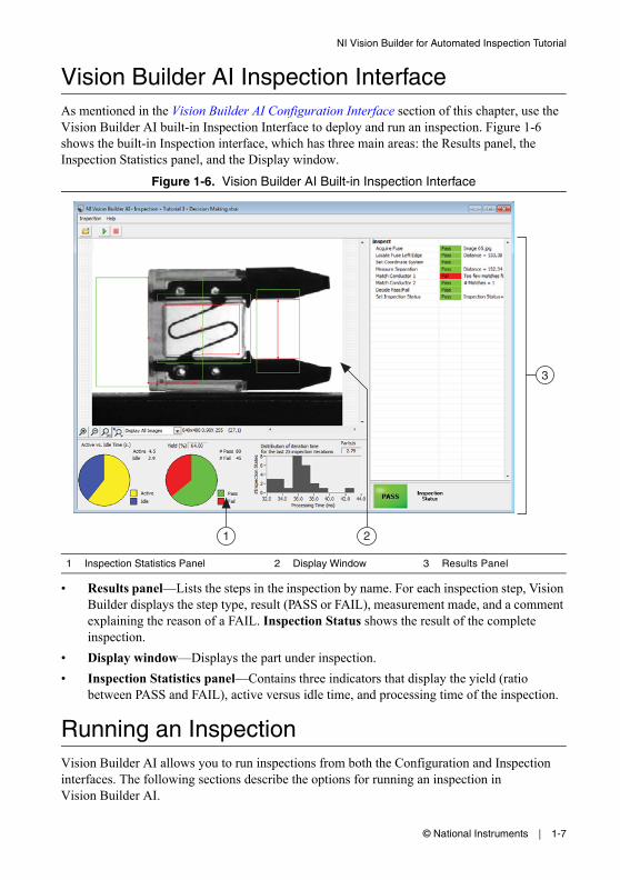
Vision Builder AI Inspection InterfaceAs mentioned in the Vision Builder AI Configuration Interface section of this chapter, use the Vision Builder AI built-in Inspection Interface to deploy and run an inspection. Figure 1-6 shows the built-in Inspection interface, which has three main areas: the Results panel, the Inspection Statistics panel, and the Display window.
Figure 1-6. Vision Builder AI Built-in Inspection Interface
• Results panel—Lists the steps in the inspection by name. For each inspection step, Vision Builder displays the step type, result (PASS or FAIL), measurement made, and a comment explaining the reason of a FAIL. Inspection Status shows the result of the complete inspection.
• Display window—Displays the part under inspection.• Inspection Statistics panel—Contains three indicators that display the yield (ratio
between PASS and FAIL), active versus idle time, and processing time of the inspection.
Running an InspectionVision Builder AI allows you to run inspections from both the Configuration and Inspection interfaces. The following sections describe the options for running an inspection in Vision Builder AI.
1 Inspection Statistics Panel 2 Display Window 3 Results Panel
1 2
3
1-8 | ni.com
Chapter 1 Introduction to Vision Builder AI
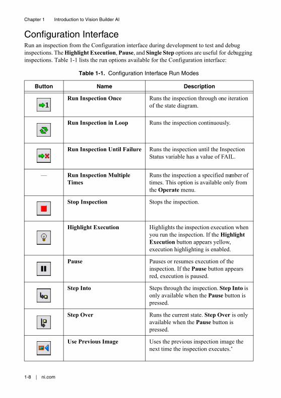
Configuration InterfaceRun an inspection from the Configuration interface during development to test and debug inspections. The Highlight Execution, Pause, and Single Step options are useful for debugging inspections. Table 1-1 lists the run options available for the Configuration interface:
Table 1-1. Configuration Interface Run Modes
Button Name Description
Run Inspection Once Runs the inspection through one iteration of the state diagram.
Run Inspection in Loop Runs the inspection continuously.
Run Inspection Until Failure Runs the inspection until the Inspection Status variable has a value of FAIL.
— Run Inspection Multiple Times
Runs the inspection a specified number of times. This option is available only from the Operate menu.
Stop Inspection Stops the inspection.
Highlight Execution Highlights the inspection execution when you run the inspection. If the Highlight Execution button appears yellow, execution highlighting is enabled.
Pause Pauses or resumes execution of the inspection. If the Pause button appears red, execution is paused.
Step Into Steps through the inspection. Step Into is only available when the Pause button is pressed.
Step Over Runs the current state. Step Over is only available when the Pause button is pressed.
Use Previous Image Uses the previous inspection image the next time the inspection executes.*
© National Instruments | 1-9
NI Vision Builder for Automated Inspection Tutorial
Inspection InterfaceAfter an inspection is configured, use the Inspection interface to run the inspection and/or deploy your system. Complete the following instructions to run an inspection from the Inspection interface:
Tip If the Vision Builder AI Configuration interface is already open, select File»Switch to Inspection Interface to open the current inspection in the Inspection interface.
1. Select Start»All Programs»National Instruments»Vision Builder AI to launch the Vision Builder AI.
2. On the Vision Builder AI welcome screen, click Browse under Run Inspection.3. Select the inspection that you want to run and click OK to open the inspection in the
Inspection Interface.
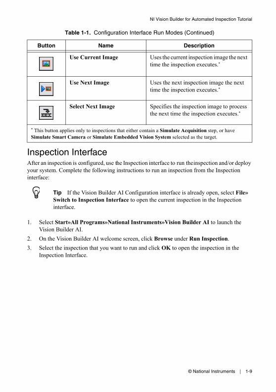
Use Current Image Uses the current inspection image the next time the inspection executes.*
Use Next Image Uses the next inspection image the next time the inspection executes.*
Select Next Image Specifies the inspection image to process the next time the inspection executes.*
* This button applies only to inspections that either contain a Simulate Acquisition step, or have Simulate Smart Camera or Simulate Embedded Vision System selected as the target.
Table 1-1. Configuration Interface Run Modes (Continued)
Button Name Description
1-10 | ni.com
Chapter 1 Introduction to Vision Builder AI
4. Click the Start Inspection button. Vision Builder AI begins running the inspection and updating the three areas of the Inspection interface with the most recent inspection data.
By default, Vision Builder AI displays all the inspection images in the Display window. You can change the display settings in the View menu to view only images that fail or to have no display. You also can change the magnification of the displayed images in the Options menu.Notice the performance data displayed in the Inspection Statistics panel. This data can help you determine how efficiently your inspection is running. Based on this data, you can make adjustments to improve the inspection speed.
5. Click the Stop Inspection button to stop the inspection.
© National Instruments | 2-1
2Checking for the Presence of a Part
This chapter introduces the Match Pattern, Measure Intensity, and Set Coordinate System steps. Follow the instructions in this chapter to create an inspection that checks for the presence of a spray bottle cap regardless of the bottle position in the inspection images.
Note Launch Vision Builder AI if it is not open. Refer to the Vision Builder AI Configuration Interface section of Chapter 1, Introduction to Vision Builder AI, for more information.
Creating a New InspectionSelect File»New to load a new, blank Vision Builder AI inspection.
Acquiring Inspection ImagesIn the Inspection Steps palette, the Acquire Images tab contains several acquisition steps you can use to acquire images from many different types of cameras. The tab also contains a Simulate Acquisition step, which simulates image acquisition by loading images from file. The Select Image step enables you to switch to a previously acquired image that you need to process later in the inspection.
For simplicity, this tutorial instructs you to use the Simulate Acquisition step. However, in your real-world inspection, use one of the other image acquisition steps to acquire images of the object under inspection.
Complete the following instructions to configure a Simulate Acquisition step that simulates acquiring images of spray bottles.1. In the Inspection Steps palette, select the Acquire Images tab.
2. Click the Simulate Acquisition step. The property page for the step opens.

2-2 | ni.com
Chapter 2 Checking for the Presence of a Part
3. In the Step Name control, enter Acquire Spray Bottle.4. Click the Browse button. The Select an Image File dialog box opens.
5. Navigate to <Vision Builder AI>\DemoImg\Tutorial 1, where <Vision Builder AI> is the location where Vision Builder AI is installed.
6. Select the first image, Image 01.jpg, and click Open.7. Make sure the Cycle Through Folder Images control is enabled so that Vision Builder AI
loads a different simulation image from the folder each time the step is run.8. Enable the Cache Images control if you want to load all of the images into memory when
the inspection opens. By default, each image is loaded individually when the step executes. 9. Click OK to add the step to the inspection.
Defining a Feature on which to Base a Coordinate SystemIn a machine vision inspection, you typically limit your inspection and processing to a region of interest (ROI) rather than the entire image for the following reasons:• To improve your inspection results by avoiding extraneous objects• To increase inspection speed
To limit the inspection area, the parts of the object you are interested in must always be inside the ROI you define.
If the object under inspection is fixtured and always appears at the same location and orientation in the images you need to process, defining an ROI is straightforward. However, if the object under inspection appears shifted or rotated within the images, the regions of interest need to shift and rotate with the object under inspection.
For the regions of interest to move in relation to the object, you need to set a coordinate system relative to a significant and original feature of the object under inspection. Choose a feature that is always in the field of view of the camera despite the different locations that the objects may appear in from image to image. Also, make sure the feature is not affected by major defects that could drastically modify the visual appearance of the feature.
Complete the following instructions to configure a Match Pattern step that locates a bottle feature on which you can base a coordinate system.1. In the Inspection Steps palette, select the Locate Features tab.
© National Instruments | 2-3
NI Vision Builder for Automated Inspection Tutorial
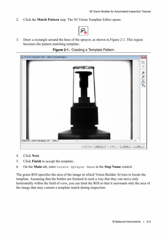
2. Click the Match Pattern step. The NI Vision Template Editor opens.
3. Draw a rectangle around the base of the sprayer, as shown in Figure 2-1. This region becomes the pattern matching template.
Figure 2-1. Creating a Template Pattern
4. Click Next.5. Click Finish to accept the template.6. On the Main tab, enter Locate Sprayer Base in the Step Name control.
The green ROI specifies the area of the image in which Vision Builder AI tries to locate the template. Assuming that the bottles are fixtured in such a way that they can move only horizontally within the field of view, you can limit the ROI so that it surrounds only the area of the image that may contain a template match during inspection.
2-4 | ni.com
Chapter 2 Checking for the Presence of a Part
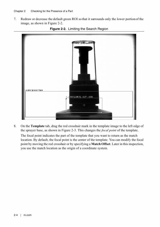
7. Redraw or decrease the default green ROI so that it surrounds only the lower portion of the image, as shown in Figure 2-2.
Figure 2-2. Limiting the Search Region
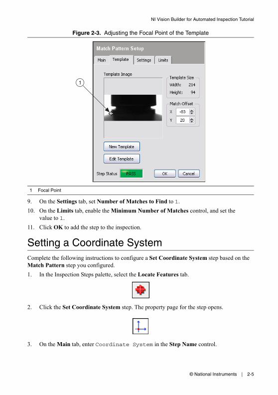
8. On the Template tab, drag the red crosshair mark in the template image to the left edge of the sprayer base, as shown in Figure 2-3. This changes the focal point of the template. The focal point indicates the part of the template that you want to return as the match location. By default, the focal point is the center of the template. You can modify the focal point by moving the red crosshair or by specifying a Match Offset. Later in this inspection, you use the match location as the origin of a coordinate system.
© National Instruments | 2-5
NI Vision Builder for Automated Inspection Tutorial
Figure 2-3. Adjusting the Focal Point of the Template
9. On the Settings tab, set Number of Matches to Find to 1.10. On the Limits tab, enable the Minimum Number of Matches control, and set the
value to 1.11. Click OK to add the step to the inspection.
Setting a Coordinate SystemComplete the following instructions to configure a Set Coordinate System step based on the Match Pattern step you configured.1. In the Inspection Steps palette, select the Locate Features tab.
2. Click the Set Coordinate System step. The property page for the step opens.
3. On the Main tab, enter Coordinate System in the Step Name control.
1 Focal Point
1
2-6 | ni.com
Chapter 2 Checking for the Presence of a Part
4. On the Settings tab, select Horizontal and Vertical Motion from the Mode control because the bottles appear shifted but not rotated from one image to another.
Notice the Origin list. Match [1], the match location of the previous Locate Sprayer Base step, is the default origin of the coordinate system because it is the only location point created by previous steps in the inspection.
5. Click OK to add the step to the inspection.
Checking for the Cap Using Measure IntensityThe image of the spray bottle was acquired using a backlight. The cap appears dark on the bright background. Complete the following instructions to configure a Measure Intensity step to check for the presence of a spray bottle cap.1. In the Inspection Steps palette, select the Measure Features tab.
2. Click the Measure Intensity step. The property page for the step opens.
3. On the Main tab, enter Check Cap Presence in the Step Name control.4. Enable the Reposition Region of Interest control.
Enabling this control allows you to link the regions of interest specified in this step to a previously defined coordinate system so that Vision Builder AI can adjust the location and orientation of the ROI from image to image relative to the specified coordinate system. The Reference Coordinate System list shows all the previously defined coordinate systems. Coordinate System is the default reference coordinate system because it is the only Set Coordinate System step in the current inspection.Notice that the Measure Intensity step supports a variety of different tools that enable you to draw different shaped regions of interest, such as a point, line, broken line, freehand line, rectangle, ellipse, annulus, polygon, and freehand region. These tools are available in the main menu bar.
© National Instruments | 2-7
NI Vision Builder for Automated Inspection Tutorial
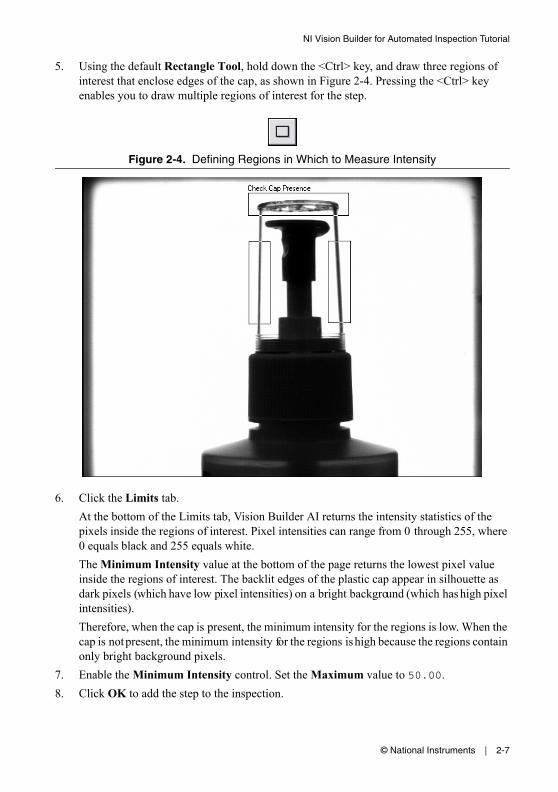
5. Using the default Rectangle Tool, hold down the <Ctrl> key, and draw three regions of interest that enclose edges of the cap, as shown in Figure 2-4. Pressing the <Ctrl> key enables you to draw multiple regions of interest for the step.
Figure 2-4. Defining Regions in Which to Measure Intensity
6. Click the Limits tab. At the bottom of the Limits tab, Vision Builder AI returns the intensity statistics of the pixels inside the regions of interest. Pixel intensities can range from 0 through 255, where 0 equals black and 255 equals white. The Minimum Intensity value at the bottom of the page returns the lowest pixel value inside the regions of interest. The backlit edges of the plastic cap appear in silhouette as dark pixels (which have low pixel intensities) on a bright background (which has high pixel intensities).Therefore, when the cap is present, the minimum intensity for the regions is low. When the cap is not present, the minimum intensity for the regions is high because the regions contain only bright background pixels.
7. Enable the Minimum Intensity control. Set the Maximum value to 50.00.8. Click OK to add the step to the inspection.
2-8 | ni.com
Chapter 2 Checking for the Presence of a Part
9. Click the Run State Once button located in the State Configuration window.
Vision Builder AI loads the next image, Image 02.jpg, from the <Vision Builder AI>\DemoImg\Tutorial 1 folder and runs the previous inspection steps in the state on the new image.Notice that the bottle appears closer to the left edge of the image. Vision Builder AI repositions the regions of interest based on the new location of the bottle. The Step Status for the image is PASS because the presence of the cap inside the regions of interest causes the Minimum Intensity value to fall within the limits you set.
Setting the Inspection StatusComplete the following instructions to add a Set Inspection Status step to determine whether the inspection passes or fails.1. In the Inspection Steps palette, select the Use Additional Tools tab.
2. Click the Set Inspection Status step. The property page for the step opens.
3. In the Inspection Status control, select the Set to FAIL if any previous step fails option.4. Click OK to add the step to the inspection.
© National Instruments | 2-9
NI Vision Builder for Automated Inspection Tutorial
Testing the InspectionTest the remaining images in the Tutorial 1 folder to make sure the inspection returns the correct results. Click the Run Inspection Once button to test the remaining images. Table 2-1 displays the expected results for each image.
Saving the InspectionComplete the following instructions to save the example inspection.1. Select File»Save or click the Save button on the toolbar.
2. Navigate to the location where you want to save the inspection.3. In the File Name control, enter Tutorial 1.vbai.4. Click Save to save the inspection.
Tip Select File»Inspection Properties to add a short description or comments about the inspection.
Table 2-1. Expected Results for the Spray Bottle Inspection
Image Name Inspection Status Explanation
Image 03.jpg PASS Cap is present.
Image 04.jpg PASS Cap is present.
Image 05.jpg FAIL Cap is missing.
© National Instruments | 3-1
3Inspecting Objects for Correct Measurements
This chapter introduces image calibration, and the Detect Objects and Geometry steps. Follow the instructions in this chapter to create an inspection that measures the distance between holes in a gasket to verify that the gasket conforms to manufacturing specifications.
Note Launch Vision Builder AI if it is not open. Refer to the Vision Builder AI Configuration Interface section of Chapter 1, Introduction to Vision Builder AI, for more information.
Creating a New InspectionSelect File»New to load a new, blank Vision Builder AI inspection.
Acquiring and Calibrating Inspection ImagesFor simplicity, this tutorial instructs you to use the Simulate Acquisition step. However, in your real-world inspection, use one of the other image acquisition steps to acquire images of the object under inspection.
Complete the following instructions to configure a Simulate Acquisition step that simulates acquiring images of gaskets.1. In the Inspection Steps palette, select the Acquire Images tab.
2. Click the Simulate Acquisition step. The property page for the step opens.
3. In the Step Name control, enter Acquire Gasket.4. Click the Browse button. The Select an Image File dialog box opens.
3-2 | ni.com
Chapter 3 Inspecting Objects for Correct Measurements
5. Navigate to <Vision Builder AI>\DemoImg\Tutorial 2, where <Vision Builder AI> is the location where Vision Builder AI is installed.
6. Select the first image, Image 01.jpg, and click Open.7. Make sure that the Cycle Through Folder Images control is enabled so that Vision Builder
AI loads a different simulation image from the folder each time the step is run.
By default, Vision Builder AI returns measurements in pixel units. If you want the inspection to return measurements in real-world units, you need to map pixel units to real-world units through a process called spatial calibration.8. Click the Calibration tab.9. Click Create Calibration to launch the calibration training interface.10. In the Calibration Name control, enter Gasket Calibration.11. Click Next.
For this example, assume that the camera that acquired the inspection images is perpendicular to the image plane and lens distortion is negligible. Based on these assumptions, you can use Point Distance Calibration to calibrate your images. Point Distance Calibration transforms a pixel coordinate to a real-world coordinate through scaling in the x (horizontal) and y (vertical) directions.12. Select the Point Distance Calibration option, and click Next.13. Make sure that the current image is selected, and click Next.
© National Instruments | 3-3
NI Vision Builder for Automated Inspection Tutorial
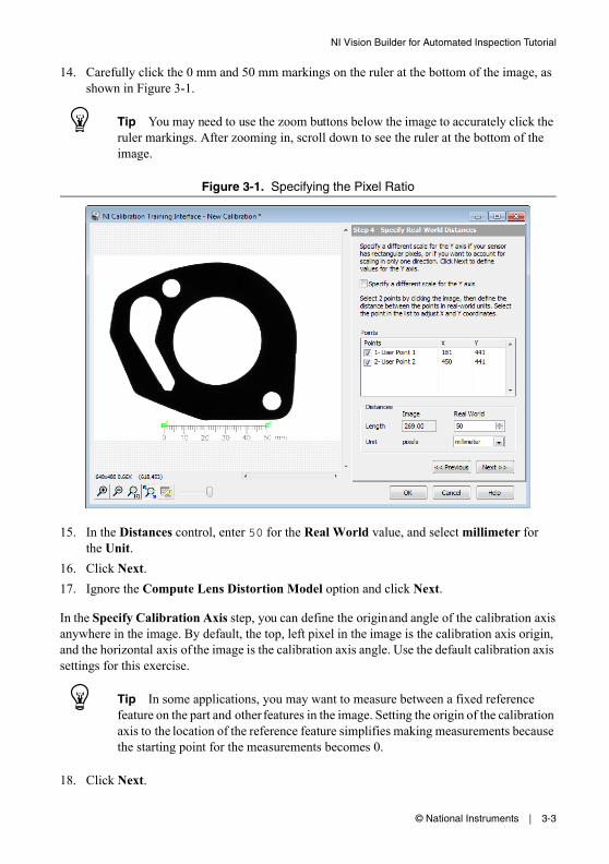
14. Carefully click the 0 mm and 50 mm markings on the ruler at the bottom of the image, as shown in Figure 3-1.
Tip You may need to use the zoom buttons below the image to accurately click the ruler markings. After zooming in, scroll down to see the ruler at the bottom of the image.
Figure 3-1. Specifying the Pixel Ratio
15. In the Distances control, enter 50 for the Real World value, and select millimeter for the Unit.
16. Click Next.17. Ignore the Compute Lens Distortion Model option and click Next.
In the Specify Calibration Axis step, you can define the origin and angle of the calibration axis anywhere in the image. By default, the top, left pixel in the image is the calibration axis origin, and the horizontal axis of the image is the calibration axis angle. Use the default calibration axis settings for this exercise.
Tip In some applications, you may want to measure between a fixed reference feature on the part and other features in the image. Setting the origin of the calibration axis to the location of the reference feature simplifies making measurements because the starting point for the measurements becomes 0.
18. Click Next.
3-4 | ni.com
Chapter 3 Inspecting Objects for Correct Measurements
19. Click OK to learn the calibration information and exit the calibration training interface. 20. Click OK to add the step to the inspection.
Vision Builder AI saves the calibration in the following locations: • (Windows XP/Server 2003 R2 (32-bit)) C:\Documents and Settings\All
Users\Application Data\National Instruments\Vision Builder AI\Calibration
• (Windows 7/Vista/Server 2008 R2) C:\ProgramData\National Instruments\Vision Builder AI\Calibration
Tip You can apply the learned calibration to all images acquired with the same camera at the same resolution.
Locating Features to MeasureComplete the following instructions to configure a Detect Objects step that finds small holes in the gasket.1. In the Inspection Steps palette, select the Check for Presence tab.
2. Click the Detect Objects step. The property page for the step opens.
3. In the Step Name control, enter Detect Small Holes.
© National Instruments | 3-5
NI Vision Builder for Automated Inspection Tutorial
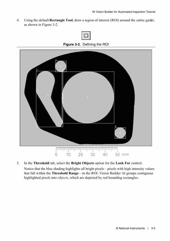
4. Using the default Rectangle Tool, draw a region of interest (ROI) around the entire gasket, as shown in Figure 3-2.
Figure 3-2. Defining the ROI
5. In the Threshold tab, select the Bright Objects option for the Look For control.Notice that the blue shading highlights all bright pixels—pixels with high intensity values that fall within the Threshold Range—in the ROI. Vision Builder AI groups contiguous highlighted pixels into objects, which are depicted by red bounding rectangles.
3-6 | ni.com
Chapter 3 Inspecting Objects for Correct Measurements
6. Click the Settings tab.The step locates four objects, which are listed in Table 3-1. Depending on the location of the user-defined points previously configured in the calibration, the values for the Size (mm2) may differ slightly from the values shown in Table 3-1.
Object 1 and Object 4 are the small holes of interest in this step. The following steps describe how to use the Minimum Object Size and Maximum Object Size controls of the Detect Objects step to eliminate objects of no interest based on their size.
7. Enable the Minimum Object Size and Maximum Object Size controls.Based on the information in Table 3-1, the small holes have sizes of 61.97 mm2 and 61.04 mm2.
8. Set Minimum Object Size to 50 and Maximum Object Size to 70.9. In the Limits tab, enable the Minimum Number of Objects and Maximum Number of
Objects controls. Set their values to 2.10. Click OK to add the step to the inspection.
Complete the following instructions to find the large hole in the gasket.1. Right-click the Detect Small Holes step in the State Configuration window, and
select Copy.2. Right-click the Detect Small Holes step again.3. Select Paste. A copy of the Detect Small Holes step is placed after the original step.4. Double-click the Detect Small Holes copy or click the Edit Step button to launch the
property page of the step for editing.
5. In the Step Name control, enter Detect Large Hole.6. Select the Settings tab.
Based on the information in Table 3-1, the large hole has a size of 1410.15 mm2.7. Set Minimum Object Size to 1300 and Maximum Object Size to 1450.
Table 3-1. Sizes of Gasket Holes
Object Number Size (mm2)
1 62.43
2 461.26
3 1410.15
4 61.50
© National Instruments | 3-7
NI Vision Builder for Automated Inspection Tutorial
8. In the Limits tab, enable the Minimum Number of Objects and Maximum Number of Objects controls. Set their values to 1.
9. Click OK to add the step to the inspection.
Measuring Parts of the GasketComplete the following instructions to measure the distance from the top small hole to the large hole to inspect whether the distance meets specifications.
Note Vision Builder AI returns the centers of mass for the holes as their locations.
1. In the Inspection Steps palette, select the Measure Features tab.
2. Click the Geometry step. The property page for the step opens.
3. In the Step Name control, enter Check Top Distance.4. In the Geometric Feature control, select the Distance measurement.
5. Select points 1 and 3 by selecting the points from the Available Points list.6. In the Limits tab, enable the Minimum Distance control and set it to 32. Enable the
Maximum Distance control and set it to 35.7. Click OK to add the step to the inspection.
Complete the following instructions to measure the distance from the large hole to the bottom small hole to inspect whether the distance meets specifications.1. Right-click the Top Distance step in the State Configuration window, and select Copy.2. Right-click the Top Distance step again.3. Select Paste. A copy of the Top Distance step is placed after the original step.4. Double-click the Top Distance copy or click the Edit Step button to launch the property
page of the step for editing.5. In the Step Name control, enter Check Bottom Distance.6. In the Geometric Feature control, select the Distance measurement.
3-8 | ni.com
Chapter 3 Inspecting Objects for Correct Measurements
7. From the Available Points list, select 2 and 3, which correspond to the bottom small hole and large hole, respectively.
8. In the Limits tab, enable the Minimum Distance control and set it to 38. Enable the Maximum Distance control and set it to 40.
9. Click OK to add the step to the inspection.
Setting the Inspection StatusComplete the following instructions to add a Set Inspection Status step to determine whether the inspection passes or fails.1. In the Inspection Steps palette, select the Use Additional Tools tab.
2. Click the Set Inspection Status step. The property page for the step opens.
3. In the Inspection Status control, select the Set to FAIL if any previous step fails option.4. Click OK to add the step to the inspection.
© National Instruments | 3-9
NI Vision Builder for Automated Inspection Tutorial
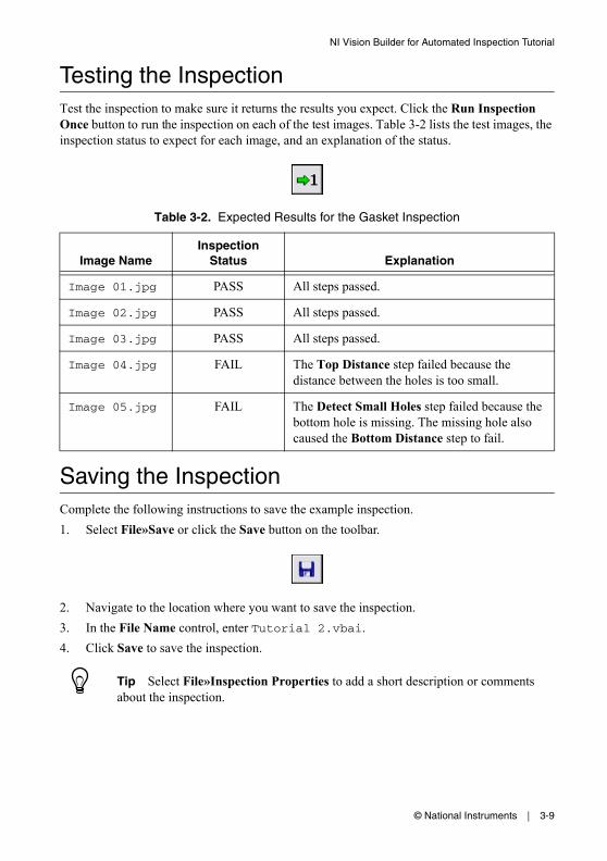
Testing the InspectionTest the inspection to make sure it returns the results you expect. Click the Run Inspection Once button to run the inspection on each of the test images. Table 3-2 lists the test images, the inspection status to expect for each image, and an explanation of the status.
Saving the InspectionComplete the following instructions to save the example inspection.1. Select File»Save or click the Save button on the toolbar.
2. Navigate to the location where you want to save the inspection.3. In the File Name control, enter Tutorial 2.vbai.4. Click Save to save the inspection.
Tip Select File»Inspection Properties to add a short description or comments about the inspection.
Table 3-2. Expected Results for the Gasket Inspection
Image NameInspection
Status Explanation
Image 01.jpg PASS All steps passed.
Image 02.jpg PASS All steps passed.
Image 03.jpg PASS All steps passed.
Image 04.jpg FAIL The Top Distance step failed because the distance between the holes is too small.
Image 05.jpg FAIL The Detect Small Holes step failed because the bottom hole is missing. The missing hole also caused the Bottom Distance step to fail.
© National Instruments | 4-1
4Inspecting for Multiple Correct Instances of an Object
This chapter introduces the Find Straight Edge, Caliper, and Decision Making steps. Follow the instructions in this chapter to create an inspection that measures the distance between the blade connectors of a fuse and checks the integrity of the fuse conductor regardless of the fuse position or whether the fuse is inverted.
Note Launch Vision Builder AI if it is not open. Refer to the Vision Builder AI Configuration Interface section of Chapter 1, Introduction to Vision Builder AI, for more information.
Creating a New InspectionSelect File»New to load a new, blank Vision Builder AI inspection.
Acquiring Inspection ImagesFor simplicity, this tutorial instructs you to use the Simulate Acquisition step. However, in your real-world inspection, use one of the other image acquisition steps to acquire images of the object under inspection.
Complete the following instructions to configure a Simulate Acquisition step that simulates acquiring images of fuses.1. In the Inspection Steps palette, select the Acquire Images tab.
2. Click the Simulate Acquisition step. The property page for the step opens.
3. In the Step Name control, enter Acquire Fuse.
4-2 | ni.com
Chapter 4 Inspecting for Multiple Correct Instances of an Object
4. Click the Browse button. The Select an Image File dialog box opens.
5. Navigate to <Vision Builder AI>\DemoImg\Tutorial 3, where <Vision Builder AI> is the location where Vision Builder AI is installed.
6. Select the first image, Image 01.jpg, and click Open.7. Make sure the Cycle Through Folder Images control is enabled so that Vision Builder AI
loads a different simulation image from the folder each time the step is run.8. Click OK to add the step to the inspection.
Defining a Feature on which to Base a Coordinate SystemThe fuses can appear shifted horizontally and slightly rotated from one inspection image to another. Complete the following instructions to configure a Find Straight Edge step that finds the left edge of the fuse so that regions of interest in subsequent steps can shift with the fuse.1. In the Inspection Steps palette, select the Locate Features tab.
2. Click the Find Straight Edge step. The property page for the step opens.
3. In the Step Name control, enter Locate Fuse Left Edge.
© National Instruments | 4-3
NI Vision Builder for Automated Inspection Tutorial
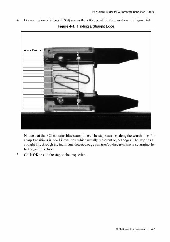
4. Draw a region of interest (ROI) across the left edge of the fuse, as shown in Figure 4-1.
Figure 4-1. Finding a Straight Edge
Notice that the ROI contains blue search lines. The step searches along the search lines for sharp transitions in pixel intensities, which usually represent object edges. The step fits a straight line through the individual detected edge points of each search line to determine the left edge of the fuse.
5. Click OK to add the step to the inspection.
4-4 | ni.com
Chapter 4 Inspecting for Multiple Correct Instances of an Object
Setting a Coordinate SystemComplete the following instructions to configure a Set Coordinate System step based on the Find Straight Edge step you configured.1. In the Inspection Steps palette, select the Locate Features tab.
2. Click the Set Coordinate System step. The property page for the step opens.
3. In the Main tab, enter Set Coordinate System in the Step Name control.4. In the Settings tab, select Horizontal Motion from the Mode control.
Notice the Origin list. Point 1, the first point of the straight line detected by the Locate Fuse Left Edge step, is the default origin of the coordinate system. In this exercise, the location of the origin does not affect the measurement you need to make. Therefore, use the default origin.
5. Click OK to add the step to the inspection.
Measuring the Separation between ConnectorsComplete the following instructions to configure a Caliper step that measures the distance between the blade connectors of the fuse.1. In the Inspection Steps palette, select the Measure Features tab.
2. Click the Caliper step. The property page for the step opens.
3. In the Main tab, enter Measure Separation in the Step Name control.4. Enable the Reposition Region of Interest control.
© National Instruments | 4-5
NI Vision Builder for Automated Inspection Tutorial
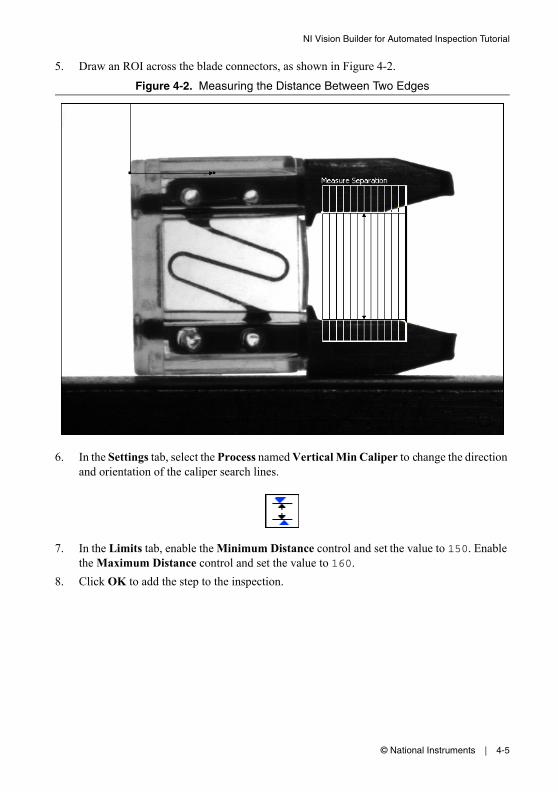
5. Draw an ROI across the blade connectors, as shown in Figure 4-2.
Figure 4-2. Measuring the Distance Between Two Edges
6. In the Settings tab, select the Process named Vertical Min Caliper to change the direction and orientation of the caliper search lines.
7. In the Limits tab, enable the Minimum Distance control and set the value to 150. Enable the Maximum Distance control and set the value to 160.
8. Click OK to add the step to the inspection.
4-6 | ni.com
Chapter 4 Inspecting for Multiple Correct Instances of an Object
Inspecting the Fuse ConductorComplete the following instructions to configure Match Pattern steps that inspect the integrity of the fuse conductor.1. In the Inspection Steps palette, select the Locate Features tab.
2. Click the Match Pattern step. The NI Vision Template Editor opens.
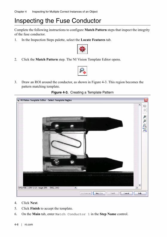
3. Draw an ROI around the conductor, as shown in Figure 4-3. This region becomes the pattern matching template.
Figure 4-3. Creating a Template Pattern
4. Click Next.5. Click Finish to accept the template.6. On the Main tab, enter Match Conductor 1 in the Step Name control.
© National Instruments | 4-7
NI Vision Builder for Automated Inspection Tutorial
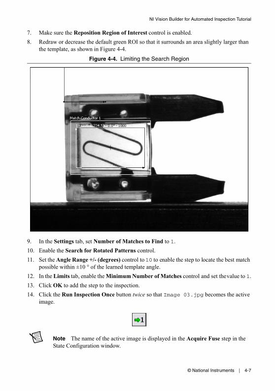
7. Make sure the Reposition Region of Interest control is enabled.8. Redraw or decrease the default green ROI so that it surrounds an area slightly larger than
the template, as shown in Figure 4-4.
Figure 4-4. Limiting the Search Region
9. In the Settings tab, set Number of Matches to Find to 1.10. Enable the Search for Rotated Patterns control.11. Set the Angle Range +/- (degrees) control to 10 to enable the step to locate the best match
possible within ±10 ° of the learned template angle.12. In the Limits tab, enable the Minimum Number of Matches control and set the value to 1.13. Click OK to add the step to the inspection.14. Click the Run Inspection Once button twice so that Image 03.jpg becomes the active
image.
Note The name of the active image is displayed in the Acquire Fuse step in the State Configuration window.
4-8 | ni.com
Chapter 4 Inspecting for Multiple Correct Instances of an Object
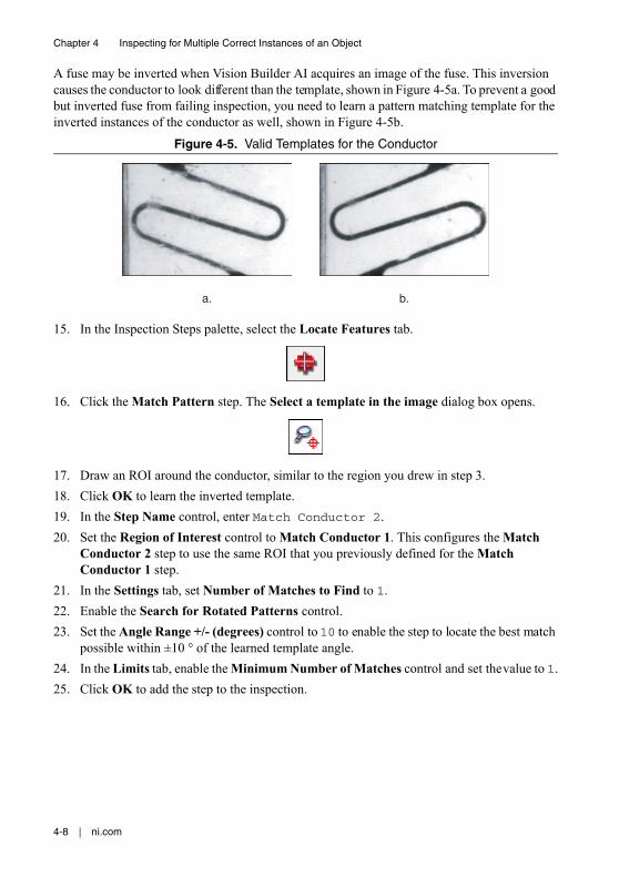
A fuse may be inverted when Vision Builder AI acquires an image of the fuse. This inversion causes the conductor to look different than the template, shown in Figure 4-5a. To prevent a good but inverted fuse from failing inspection, you need to learn a pattern matching template for the inverted instances of the conductor as well, shown in Figure 4-5b.
Figure 4-5. Valid Templates for the Conductor
15. In the Inspection Steps palette, select the Locate Features tab.
16. Click the Match Pattern step. The Select a template in the image dialog box opens.
17. Draw an ROI around the conductor, similar to the region you drew in step 3.18. Click OK to learn the inverted template.19. In the Step Name control, enter Match Conductor 2.20. Set the Region of Interest control to Match Conductor 1. This configures the Match
Conductor 2 step to use the same ROI that you previously defined for the Match Conductor 1 step.
21. In the Settings tab, set Number of Matches to Find to 1.22. Enable the Search for Rotated Patterns control.23. Set the Angle Range +/- (degrees) control to 10 to enable the step to locate the best match
possible within ±10 ° of the learned template angle.24. In the Limits tab, enable the Minimum Number of Matches control and set the value to 1.25. Click OK to add the step to the inspection.
a. b.
© National Instruments | 4-9
NI Vision Builder for Automated Inspection Tutorial
Making Logical PASS/FAIL DecisionsIn the previous lessons, the inspection would fail if any of the steps in the inspection failed. In this lesson, because the conductor under inspection can match only one of the patterns you specified, one of the Match Pattern steps always fails. If you were to set the Inspection Status to fail if any of the steps in the inspection fail, the entire inspection will always fail because one of the Match Pattern steps always fails.
Using the Logic Calculator step, you can create a Boolean result that is based on the results of the previous inspection steps. The Set Inspection Status step can use this Boolean result to determine the Inspection Status.
Complete the following instructions to configure a Logic Calculator step that causes the inspection to pass when the conductor matches either the template in Match Conductor 1 or Match Conductor 2, and when the Measure Separation step passes.1. In the Inspection Steps palette, select the Use Additional Tools tab.
2. Click the Logic Calculator step. The property page opens in the Main window.
3. In the Step Name control, enter Decide Pass/Fail.4. In the First Operand frame, set Source to Measure Separation. Set Measure to Step
Status.Current Value displays the value of the measurement based on the current image.
5. Make sure Second Operand is set to Constant, and Constant is set to True.6. Click Add to add this expression to the Expression table.7. In the First Operand frame, set Source to Match Conductor 1. Set Measure to Step
Status.8. Make sure Second Operand is set to Constant, and Constant is set to True.9. Click Add to add this expression to the Expression table.
Notice the default binary operator AND in the last column of the Expression table.10. In the First Operand frame, set Source to Match Conductor 2. Set Measure to Step
Status.11. Make sure Second Operand is set to Constant and Constant is set to True.12. Click Add to add this expression to the Expression table.13. Select the second expression in the Expression table, and click AND/OR to change the
binary operator to OR.
4-10 | ni.com
Chapter 4 Inspecting for Multiple Correct Instances of an Object
14. Hold down the <Shift> key, and select the second and third expressions in the Expression table.
15. Click ( ) to group the expressions.
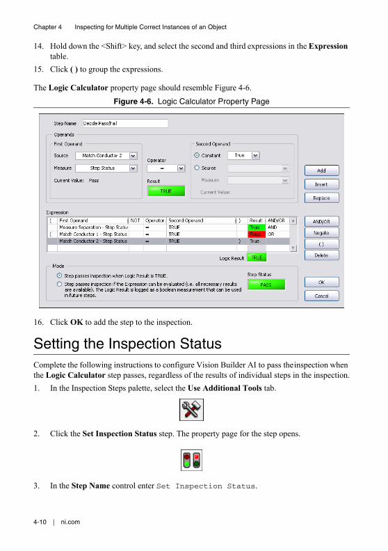
The Logic Calculator property page should resemble Figure 4-6.
Figure 4-6. Logic Calculator Property Page
16. Click OK to add the step to the inspection.
Setting the Inspection StatusComplete the following instructions to configure Vision Builder AI to pass the inspection when the Logic Calculator step passes, regardless of the results of individual steps in the inspection.1. In the Inspection Steps palette, select the Use Additional Tools tab.
2. Click the Set Inspection Status step. The property page for the step opens.
3. In the Step Name control enter Set Inspection Status.
© National Instruments | 4-11
NI Vision Builder for Automated Inspection Tutorial
4. In the Inspection Status control select the Set to measurement value option, and select Decide Pass/Fail - Step Status for the value.
5. Make sure the Update Number of Parts Inspected control is enabled.6. Click OK to add the step to the inspection.
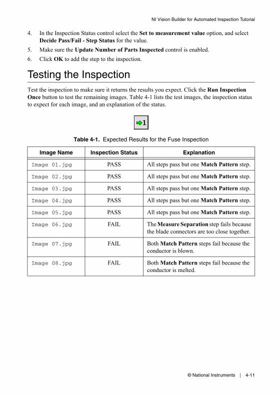
Testing the InspectionTest the inspection to make sure it returns the results you expect. Click the Run Inspection Once button to test the remaining images. Table 4-1 lists the test images, the inspection status to expect for each image, and an explanation of the status.
Table 4-1. Expected Results for the Fuse Inspection
Image Name Inspection Status Explanation
Image 01.jpg PASS All steps pass but one Match Pattern step.
Image 02.jpg PASS All steps pass but one Match Pattern step.
Image 03.jpg PASS All steps pass but one Match Pattern step.
Image 04.jpg PASS All steps pass but one Match Pattern step.
Image 05.jpg PASS All steps pass but one Match Pattern step.
Image 06.jpg FAIL The Measure Separation step fails because the blade connectors are too close together.
Image 07.jpg FAIL Both Match Pattern steps fail because the conductor is blown.
Image 08.jpg FAIL Both Match Pattern steps fail because the conductor is melted.

4-12 | ni.com
Chapter 4 Inspecting for Multiple Correct Instances of an Object
Saving the InspectionComplete the following instructions to save the example inspection.1. Select File»Save or click the Save button on the toolbar.
2. Navigate to the location where you want to save the inspection.3. In the File Name control, enter Tutorial 3.vbai.4. Click Save to save the inspection.
Tip Select File»Inspection Properties to add a short description or comments about the inspection.
© National Instruments | 5-1
5Inspecting an Object that Spans Two Image Frames
This chapter introduces the Select Image and Calculator steps.
Assume that you need to measure the width of a wide wooden plank with high accuracy. The only cameras available for the application have low pixel resolutions.
To measure the width of a plank, you need to locate its left and right edges. If you were to set up the imaging system so both edges of a plank fit within an available camera’s field of view, the resulting image detail would be too low to yield accurate measurements. Because the required image detail exceeds the pixel resolution capability of a single camera, two cameras per plank are needed—one camera to acquire an image of the left edge and one camera to acquire an image of the right edge.
Follow the instructions in this chapter to create an inspection that measures the width of a wooden plank that spans two images.
Note Launch Vision Builder AI if it is not open. Refer to the Vision Builder AI Configuration Interface section of Chapter 1, Introduction to Vision Builder AI, for more information.
Creating a New InspectionSelect File»New to load a new, blank Vision Builder AI inspection.
Acquiring Inspection Images from Two CamerasFor simplicity, this tutorial instructs you to use the Simulate Acquisition step. However, in your real-world inspection, use one of the other image acquisition steps to acquire images of the object under inspection.
5-2 | ni.com
Chapter 5 Inspecting an Object that Spans Two Image Frames
Acquiring and Calibrating the Image of the Left EdgeComplete the following instructions to configure Simulate Acquisition steps that simulate acquiring an image of the left section of the wooden plank and calibrating the image.1. In the Inspection Steps palette, select the Acquire Images tab.
2. Click the Simulate Acquisition step. The property page for the step opens.
3. In the Step Name control, enter Acquire Plank (Left).4. Click the Browse button. The Select an Image File dialog box opens.
5. Navigate to <Vision Builder AI>\DemoImg\Tutorial 4 Left, where <Vision Builder AI> is the location where Vision Builder AI is installed.
6. Select the first image, Image 01.jpg, and click Open.7. Make sure that the Cycle Through Folder Images control is enabled so that Vision Builder
AI loads a different simulation image from the folder each time the step is run.8. Click the Calibration tab.9. Click Create Calibration to launch the calibration training interface.10. In the Calibration Name control, enter Plank Calibration (Left).11. Click Next.
For this example, assume that the camera that acquired the inspection images is perpendicular to the image plane and lens distortion is negligible. Based on these assumptions, you can use Point Distance Calibration to calibrate your images. Point Distance Calibration transforms a pixel coordinate to a real-world coordinate through scaling in the x (horizontal) and y (vertical) directions.12. Select the Point Distance Calibration option, and click Next.13. Make sure that the current image is selected, and click Next.
© National Instruments | 5-3
NI Vision Builder for Automated Inspection Tutorial
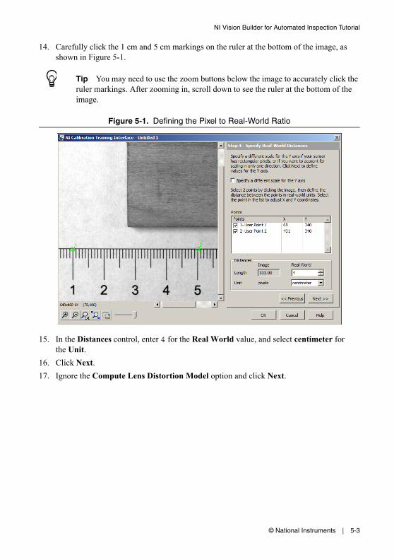
14. Carefully click the 1 cm and 5 cm markings on the ruler at the bottom of the image, as shown in Figure 5-1.
Tip You may need to use the zoom buttons below the image to accurately click the ruler markings. After zooming in, scroll down to see the ruler at the bottom of the image.
Figure 5-1. Defining the Pixel to Real-World Ratio
15. In the Distances control, enter 4 for the Real World value, and select centimeter for the Unit.
16. Click Next.17. Ignore the Compute Lens Distortion Model option and click Next.
5-4 | ni.com
Chapter 5 Inspecting an Object that Spans Two Image Frames
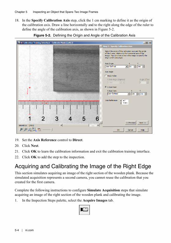
18. In the Specify Calibration Axis step, click the 1 cm marking to define it as the origin of the calibration axis. Draw a line horizontally and to the right along the edge of the ruler to define the angle of the calibration axis, as shown in Figure 5-2.
Figure 5-2. Defining the Origin and Angle of the Calibration Axis
19. Set the Axis Reference control to Direct.20. Click Next.21. Click OK to learn the calibration information and exit the calibration training interface.22. Click OK to add the step to the inspection.
Acquiring and Calibrating the Image of the Right EdgeThis section simulates acquiring an image of the right section of the wooden plank. Because the simulated acquisition represents a second camera, you cannot reuse the calibration that you created for the first camera.
Complete the following instructions to configure Simulate Acquisition steps that simulate acquiring an image of the right section of the wooden plank and calibrating the image.1. In the Inspection Steps palette, select the Acquire Images tab.
© National Instruments | 5-5
NI Vision Builder for Automated Inspection Tutorial
2. Click the Simulate Acquisition step. The property page for the step opens.
3. In the Step Name control, enter Acquire Plank (Right).4. Click the Browse button. The Select an Image File dialog box opens.
5. Navigate to <Vision Builder AI>\DemoImg\Tutorial 4 Right, where <Vision Builder AI> is the location where Vision Builder AI is installed.
6. Select the first image, Image 01.jpg, and click Open.7. Make sure the Cycle Through Folder Images control is enabled so that Vision Builder AI
loads a different simulation image from the folder each time the step is run.8. Click the Calibration tab.9. Click Create Calibration to launch the calibration training interface.10. In the Calibration Name control, enter Plank Calibration (Right).11. Click Next.
Again, assume that the camera that acquired the inspection images is perpendicular to the image plane and lens distortion is negligible. 12. Select the Point Distance Calibration option, and click Next.13. Make sure the current image is selected, and click Next.
5-6 | ni.com
Chapter 5 Inspecting an Object that Spans Two Image Frames
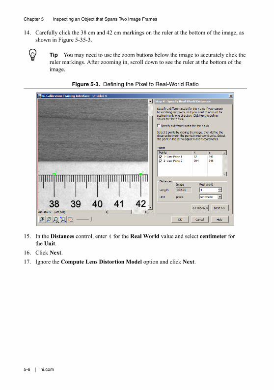
14. Carefully click the 38 cm and 42 cm markings on the ruler at the bottom of the image, as shown in Figure 5-35-3.
Tip You may need to use the zoom buttons below the image to accurately click the ruler markings. After zooming in, scroll down to see the ruler at the bottom of the image.
Figure 5-3. Defining the Pixel to Real-World Ratio
15. In the Distances control, enter 4 for the Real World value and select centimeter for the Unit.
16. Click Next.17. Ignore the Compute Lens Distortion Model option and click Next.
© National Instruments | 5-7
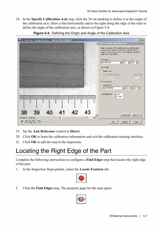
NI Vision Builder for Automated Inspection Tutorial
18. In the Specify Calibration Axis step, click the 38 cm marking to define it as the origin of the calibration axis. Draw a line horizontally and to the right along the edge of the ruler to define the angle of the calibration axis, as shown in Figure 5-4.
Figure 5-4. Defining the Origin and Angle of the Calibration Axis
19. Set the Axis Reference control to Direct.20. Click OK to learn the calibration information and exit the calibration training interface.21. Click OK to add the step to the inspection.
Locating the Right Edge of the PartComplete the following instructions to configure a Find Edges step that locates the right edge of the part.1. In the Inspection Steps palette, select the Locate Features tab.
2. Click the Find Edges step. The property page for the step opens.
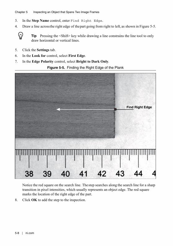
5-8 | ni.com
Chapter 5 Inspecting an Object that Spans Two Image Frames
3. In the Step Name control, enter Find Right Edge.4. Draw a line across the right edge of the part going from right to left, as shown in Figure 5-5.
Tip Pressing the <Shift> key while drawing a line constrains the line tool to only draw horizontal or vertical lines.
5. Click the Settings tab.6. In the Look for control, select First Edge.7. In the Edge Polarity control, select Bright to Dark Only.
Figure 5-5. Finding the Right Edge of the Plank
Notice the red square on the search line. The step searches along the search line for a sharp transition in pixel intensities, which usually represents an object edge. The red square marks the location of the right edge of the part.
8. Click OK to add the step to the inspection.
Find Right Edge
© National Instruments | 5-9
NI Vision Builder for Automated Inspection Tutorial
Switching ImagesNow that you have configured the inspection to locate the right edge of the wooden plank, you need to switch to the image of the left side of the plank. Complete the following instructions to configure a Select Image step that makes the image of the left side of the plank active for processing.1. In the Inspection Steps palette, select the Acquire Images tab.
2. Click the Select Image step. The property page for the step opens.
3. In the Step Name control, enter Switch to Left Side.4. In the Image Selection list, select Acquire Plank (Left). The image of the left side of the
part appears in the Main window.5. Click OK to add the step to the inspection.
Locating the Left Edge of the PartComplete the following instructions to configure a Find Edges step that locates the left edge of the part.1. In the Inspection Steps palette, select the Locate Features tab.
2. Click the Find Edges step. The property page for the step opens.3. In the Step Name control, enter Find Left Edge.
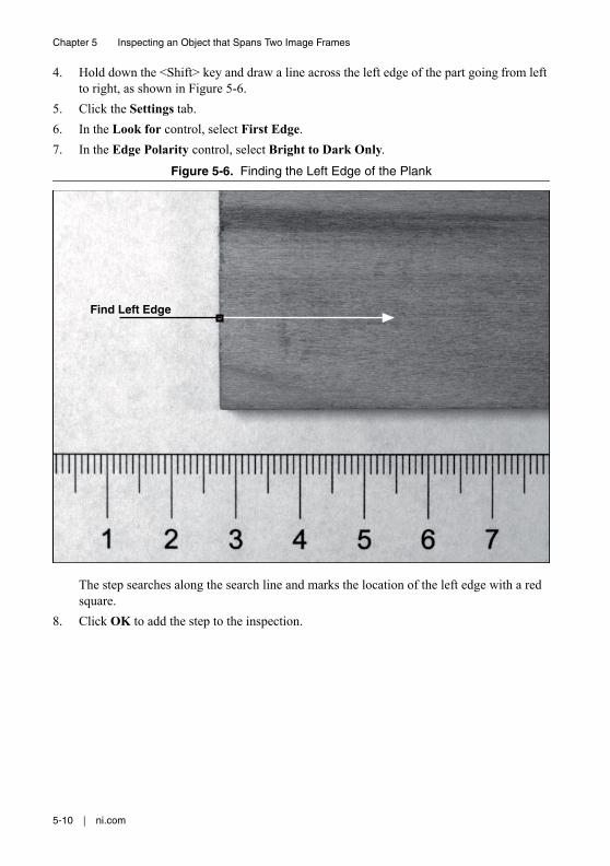
5-10 | ni.com
Chapter 5 Inspecting an Object that Spans Two Image Frames
4. Hold down the <Shift> key and draw a line across the left edge of the part going from left to right, as shown in Figure 5-6.
5. Click the Settings tab.6. In the Look for control, select First Edge.7. In the Edge Polarity control, select Bright to Dark Only.
Figure 5-6. Finding the Left Edge of the Plank
The step searches along the search line and marks the location of the left edge with a red square.
8. Click OK to add the step to the inspection.
Find Left Edge
© National Instruments | 5-11
NI Vision Builder for Automated Inspection Tutorial
Calculating the Width of the PartNow that you have located the right edge of the part in one image and the left edge of the part in another image, you need to combine the measurements from the two images to determine the width of the part. Use the Calculator step to combine the two measurements and compute the width.
Refer to the following equations as you configure the step.
Right (LC) = Right (RC) + (Origin R - Origin L) (5-1)
Part Width = Right (LC) - Left (LC) (5-2)
where Right (LC) = The x position of the right edge in the calibration axis of the left edge.
Right (RC) = The x position of the right edge in the calibration axis of the right edge. This corresponds to the calibrated x position result of the Find Right Edge step.
Origin R = The x position of the origin in the calibration axis of the right edge.
Origin L = The x position of the origin in the calibration axis of the left edge.
Left (LC) = The x position of the left edge in the calibration axis of the left edge. This corresponds to the calibrated x position result of the Find Left Edge step.
Setting Calculator Step Inputs and OutputsComplete the following instructions to configure a Calculator step to select the input measurements from the previous Find Right Edge and Find Left Edge steps, and create output results for the calculated values.1. In the Inspection Steps palette, select the Use Additional Tools tab.
2. Click the Calculator step. The Calculator Setup Wizard opens.
3. Click Next to proceed with the wizard.
Notice the Input Measurements list. The list contains all of the measurable data from each of the previous steps in the inspection.
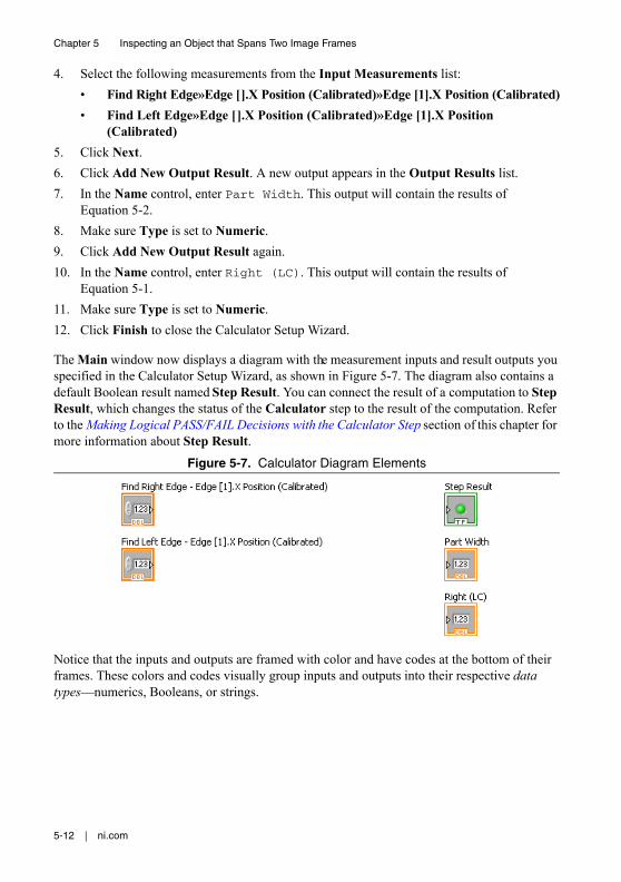
5-12 | ni.com
Chapter 5 Inspecting an Object that Spans Two Image Frames
4. Select the following measurements from the Input Measurements list:• Find Right Edge»Edge [].X Position (Calibrated)»Edge [1].X Position (Calibrated)• Find Left Edge»Edge [].X Position (Calibrated)»Edge [1].X Position
(Calibrated)5. Click Next.6. Click Add New Output Result. A new output appears in the Output Results list.7. In the Name control, enter Part Width. This output will contain the results of
Equation 5-2.8. Make sure Type is set to Numeric.9. Click Add New Output Result again.10. In the Name control, enter Right (LC). This output will contain the results of
Equation 5-1.11. Make sure Type is set to Numeric.12. Click Finish to close the Calculator Setup Wizard.
The Main window now displays a diagram with the measurement inputs and result outputs you specified in the Calculator Setup Wizard, as shown in Figure 5-7. The diagram also contains a default Boolean result named Step Result. You can connect the result of a computation to Step Result, which changes the status of the Calculator step to the result of the computation. Refer to the Making Logical PASS/FAIL Decisions with the Calculator Step section of this chapter for more information about Step Result.
Figure 5-7. Calculator Diagram Elements
Notice that the inputs and outputs are framed with color and have codes at the bottom of their frames. These colors and codes visually group inputs and outputs into their respective data types—numerics, Booleans, or strings.
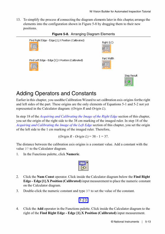
© National Instruments | 5-13
NI Vision Builder for Automated Inspection Tutorial
13. To simplify the process of connecting the diagram elements later in this chapter, arrange the elements into the configuration shown in Figure 5-8 by dragging them to their new positions.
Figure 5-8. Arranging Diagram Elements
Adding Operators and ConstantsEarlier in this chapter, you used the Calibration Wizard to set calibration axis origins for the right and left sides of the part. These origins are the only elements of Equations 5-1 and 5-2 not yet represented in the Calculator diagram: (Origin R and Origin L).
In step 18 of the Acquiring and Calibrating the Image of the Right Edge section of this chapter, you set the origin of the right side to the 38 cm marking of the imaged ruler. In step 18 of the Acquiring and Calibrating the Image of the Left Edge section of this chapter, you set the origin of the left side to the 1 cm marking of the imaged ruler. Therefore,
(Origin R - Origin L) = 38 - 1 = 37.
The distance between the calibration axis origins is a constant value. Add a constant with the value 37 to the Calculator diagram.1. In the Functions palette, click Numeric.
2. Click the Num Const operator. Click inside the Calculator diagram below the Find Right Edge - Edge [1].X Position (Calibrated) input measurement to place the numeric constant on the Calculator diagram.
3. Double-click the numeric constant and type 37 to set the value of the constant.
4. Click the Add operator in the Functions palette. Click inside the Calculator diagram to the right of the Find Right Edge - Edge [1].X Position (Calibrated) input measurement.
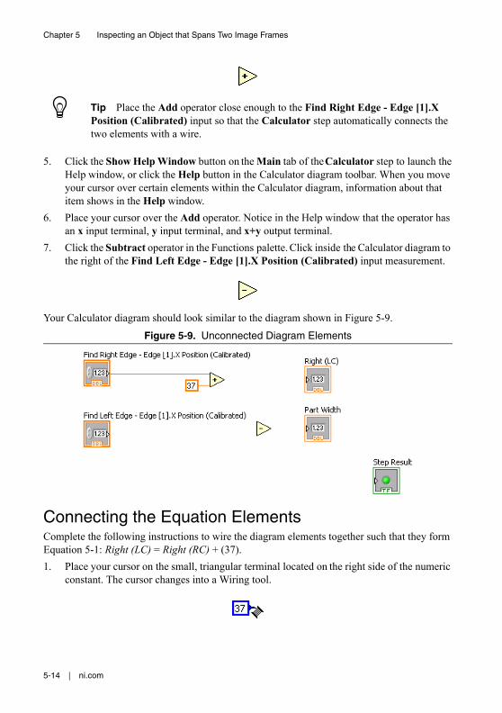
5-14 | ni.com
Chapter 5 Inspecting an Object that Spans Two Image Frames
Tip Place the Add operator close enough to the Find Right Edge - Edge [1].X Position (Calibrated) input so that the Calculator step automatically connects the two elements with a wire.
5. Click the Show Help Window button on the Main tab of the Calculator step to launch the Help window, or click the Help button in the Calculator diagram toolbar. When you move your cursor over certain elements within the Calculator diagram, information about that item shows in the Help window.
6. Place your cursor over the Add operator. Notice in the Help window that the operator has an x input terminal, y input terminal, and x+y output terminal.
7. Click the Subtract operator in the Functions palette. Click inside the Calculator diagram to the right of the Find Left Edge - Edge [1].X Position (Calibrated) input measurement.
Your Calculator diagram should look similar to the diagram shown in Figure 5-9.
Figure 5-9. Unconnected Diagram Elements
Connecting the Equation ElementsComplete the following instructions to wire the diagram elements together such that they form Equation 5-1: Right (LC) = Right (RC) + (37).1. Place your cursor on the small, triangular terminal located on the right side of the numeric
constant. The cursor changes into a Wiring tool.
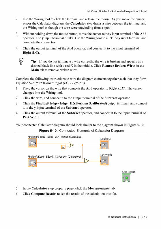
© National Instruments | 5-15
NI Vision Builder for Automated Inspection Tutorial
2. Use the Wiring tool to click the terminal and release the mouse. As you move the cursor across the Calculator diagram, the Calculator step draws a wire between the terminal and the Wiring tool as though the wire were unwinding from a spool.
3. Without holding down the mouse button, move the cursor to the y input terminal of the Add operator. The y input terminal blinks. Use the Wiring tool to click the y input terminal and complete the connection.
4. Click the output terminal of the Add operator, and connect it to the input terminal of Right (LC).
Tip If you do not terminate a wire correctly, the wire is broken and appears as a dashed black line with a red X in the middle. Click Remove Broken Wires in the Main tab to remove broken wires.
Complete the following instructions to wire the diagram elements together such that they form Equation 5-2: Part Width = Right (LC) - Left (LC).1. Place the cursor on the wire that connects the Add operator to Right (LC). The cursor
changes into the Wiring tool.2. Click the wire, and connect it to the x input terminal of the Subtract operator.3. Click the Find Left Edge - Edge [1].X Position (Calibrated) output terminal, and connect
it to the y input terminal of the Subtract operator.4. Click the output terminal of the Subtract operator, and connect it to the input terminal of
Part Width.
Your connected Calculator diagram should look similar to the diagram shown in Figure 5-10.
Figure 5-10. Connected Elements of Calculator Diagram
5. In the Calculator step property page, click the Measurements tab.6. Click Compute Results to see the results of the calculation thus far.
5-16 | ni.com
Chapter 5 Inspecting an Object that Spans Two Image Frames
Making Logical PASS/FAIL Decisions with the Calculator StepNow that you have a created a diagram to measure the width of the part, you need a way to verify that the width meets manufacturing specifications. Complete the following instructions to add diagram elements that compare the measured width to minimum and maximum width tolerances and decide whether the plank passes inspection.1. Click the up arrow in the Functions palette to return to the main palette.2. Select the Comparison palette.
3. Click the Less? operator in the Comparison palette. Click inside the Calculator diagram below Part Width.
4. Connect the wire between Subtract and Part Width to the x input of the Less? operator.5. Click the up arrow in the Functions palette to return to the main palette.6. Select the Numeric palette.7. Click the Num Const operator in the Numeric palette.8. Click close enough to the y input of Less? to automatically wire the numeric constant and
y input together.9. Type 40.5 to set the maximum width a plank can be to pass the inspection.10. Click the up arrow in the Functions palette to return to the main palette.11. Select the Comparison palette.12. Click the Greater? operator. Click inside the Calculator diagram below the Less? operator.13. Connect the wire between Subtract and Part Width to the x input of the Greater?
operator.14. Click the up arrow in the Functions palette to return to the main palette.15. Select the Numeric palette.16. Click the Num Const operator.17. Click close enough to the y input of Greater? to automatically wire the numeric constant
and y input together.18. Type 39.5 to set the minimum width a plank can be to pass the inspection.19. Click the up arrow in the Functions palette to return to the main palette.20. Select the Boolean palette.21. Click the And operator. Click close enough to the left side of Step Result to wire the two
elements together.22. Connect the Less? output to the x input of And.23. Connect the Greater? output to the y input of And.
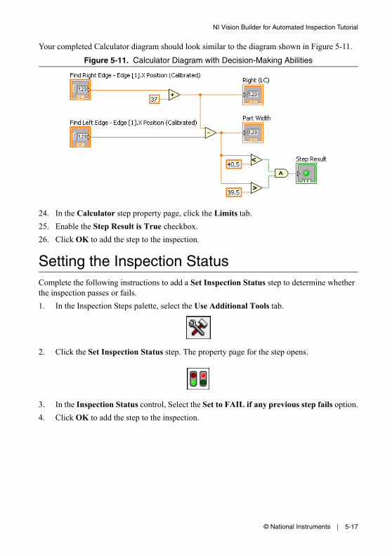
© National Instruments | 5-17
NI Vision Builder for Automated Inspection Tutorial
Your completed Calculator diagram should look similar to the diagram shown in Figure 5-11.
Figure 5-11. Calculator Diagram with Decision-Making Abilities
24. In the Calculator step property page, click the Limits tab.25. Enable the Step Result is True checkbox.26. Click OK to add the step to the inspection.
Setting the Inspection StatusComplete the following instructions to add a Set Inspection Status step to determine whether the inspection passes or fails.1. In the Inspection Steps palette, select the Use Additional Tools tab.
2. Click the Set Inspection Status step. The property page for the step opens.
3. In the Inspection Status control, Select the Set to FAIL if any previous step fails option.4. Click OK to add the step to the inspection.
5-18 | ni.com
Chapter 5 Inspecting an Object that Spans Two Image Frames
Testing the InspectionTest the inspection to make sure it returns the results you expect. Click the Run Inspection Once button to test the remaining images. Table 5-1 lists the test images, the inspection status to expect for each image, and an explanation of the status.
Note Results may vary slightly based on the accuracy of the calibration and the edge detection location.
Saving the InspectionComplete the following instructions to save the example inspection.1. Select File»Save or click the Save button on the toolbar.
2. Navigate to the location where you want to save the inspection.3. In the File Name control, enter Tutorial 4.vbai.4. Click Save to save the inspection.
Tip Select File»Inspection Properties to add a short description or comments about the inspection.
Table 5-1. Expected Results for the Plank Inspection
Image Name Part Width Inspection Status
Image 01.jpg 39.99 cm PASS
Image 02.jpg 40.12 cm PASS
Image 03.jpg 40.25 cm PASS
Image 04.jpg 39.23 cm (too short) FAIL
Image 05.jpg 40.89 cm (too long) FAIL
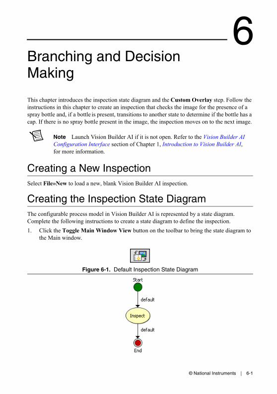
© National Instruments | 6-1
6Branching and Decision Making
This chapter introduces the inspection state diagram and the Custom Overlay step. Follow the instructions in this chapter to create an inspection that checks the image for the presence of a spray bottle and, if a bottle is present, transitions to another state to determine if the bottle has a cap. If there is no spray bottle present in the image, the inspection moves on to the next image.
Note Launch Vision Builder AI if it is not open. Refer to the Vision Builder AI Configuration Interface section of Chapter 1, Introduction to Vision Builder AI, for more information.
Creating a New InspectionSelect File»New to load a new, blank Vision Builder AI inspection.
Creating the Inspection State DiagramThe configurable process model in Vision Builder AI is represented by a state diagram. Complete the following instructions to create a state diagram to define the inspection.1. Click the Toggle Main Window View button on the toolbar to bring the state diagram to
the Main window.
Figure 6-1. Default Inspection State Diagram
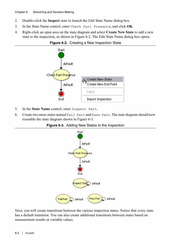
6-2 | ni.com
Chapter 6 Branching and Decision Making
2. Double-click the Inspect state to launch the Edit State Name dialog box.3. In the State Name control, enter Check Part Presence, and click OK.4. Right-click an open area on the state diagram and select Create New State to add a new
state to the inspection, as shown in Figure 6-2. The Edit State Name dialog box opens.
Figure 6-2. Creating a New Inspection State
5. In the State Name control, enter Inspect Part.6. Create two more states named Fail Part and Pass Part. The state diagram should now
resemble the state diagram shown in Figure 6-3.
Figure 6-3. Adding New States to the Inspection
Next, you will create transitions between the various inspection states. Notice that every state has a default transition. You can also create additional transitions between states based on measurement results or variable values.
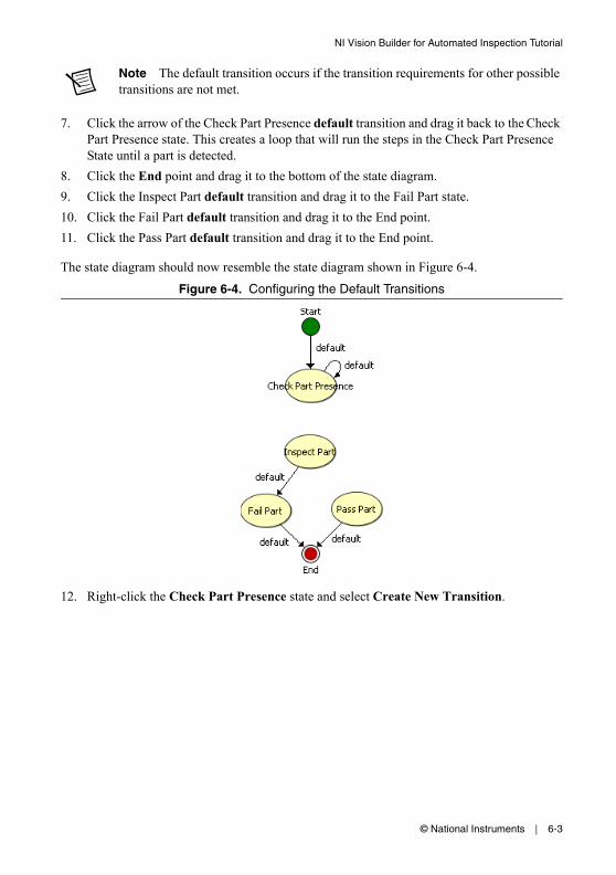
© National Instruments | 6-3
NI Vision Builder for Automated Inspection Tutorial
Note The default transition occurs if the transition requirements for other possible transitions are not met.
7. Click the arrow of the Check Part Presence default transition and drag it back to the Check Part Presence state. This creates a loop that will run the steps in the Check Part Presence State until a part is detected.
8. Click the End point and drag it to the bottom of the state diagram.9. Click the Inspect Part default transition and drag it to the Fail Part state.10. Click the Fail Part default transition and drag it to the End point.11. Click the Pass Part default transition and drag it to the End point.
The state diagram should now resemble the state diagram shown in Figure 6-4.
Figure 6-4. Configuring the Default Transitions
12. Right-click the Check Part Presence state and select Create New Transition.
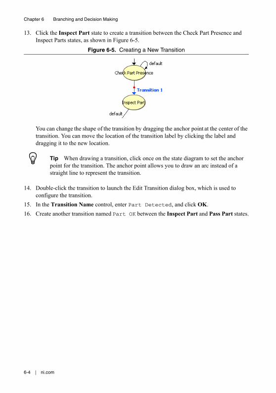
6-4 | ni.com
Chapter 6 Branching and Decision Making
13. Click the Inspect Part state to create a transition between the Check Part Presence and Inspect Parts states, as shown in Figure 6-5.
Figure 6-5. Creating a New Transition
You can change the shape of the transition by dragging the anchor point at the center of the transition. You can move the location of the transition label by clicking the label and dragging it to the new location.
Tip When drawing a transition, click once on the state diagram to set the anchor point for the transition. The anchor point allows you to draw an arc instead of a straight line to represent the transition.
14. Double-click the transition to launch the Edit Transition dialog box, which is used to configure the transition.
15. In the Transition Name control, enter Part Detected, and click OK.16. Create another transition named Part OK between the Inspect Part and Pass Part states.
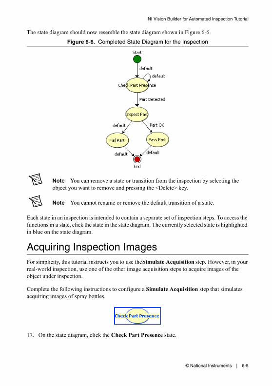
© National Instruments | 6-5
NI Vision Builder for Automated Inspection Tutorial
The state diagram should now resemble the state diagram shown in Figure 6-6.
Figure 6-6. Completed State Diagram for the Inspection
Note You can remove a state or transition from the inspection by selecting the object you want to remove and pressing the <Delete> key.
Note You cannot rename or remove the default transition of a state.
Each state in an inspection is intended to contain a separate set of inspection steps. To access the functions in a state, click the state in the state diagram. The currently selected state is highlighted in blue on the state diagram.
Acquiring Inspection ImagesFor simplicity, this tutorial instructs you to use the Simulate Acquisition step. However, in your real-world inspection, use one of the other image acquisition steps to acquire images of the object under inspection.
Complete the following instructions to configure a Simulate Acquisition step that simulates acquiring images of spray bottles.
17. On the state diagram, click the Check Part Presence state.
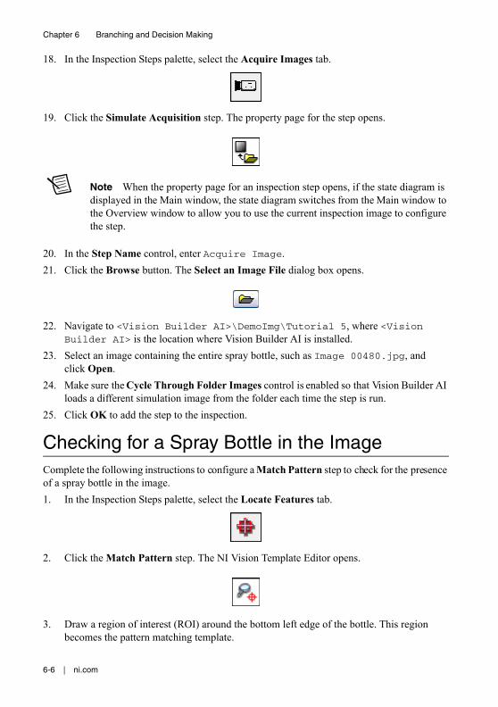
6-6 | ni.com
Chapter 6 Branching and Decision Making
18. In the Inspection Steps palette, select the Acquire Images tab.
19. Click the Simulate Acquisition step. The property page for the step opens.
Note When the property page for an inspection step opens, if the state diagram is displayed in the Main window, the state diagram switches from the Main window to the Overview window to allow you to use the current inspection image to configure the step.
20. In the Step Name control, enter Acquire Image.21. Click the Browse button. The Select an Image File dialog box opens.
22. Navigate to <Vision Builder AI>\DemoImg\Tutorial 5, where <Vision Builder AI> is the location where Vision Builder AI is installed.
23. Select an image containing the entire spray bottle, such as Image 00480.jpg, and click Open.
24. Make sure the Cycle Through Folder Images control is enabled so that Vision Builder AI loads a different simulation image from the folder each time the step is run.
25. Click OK to add the step to the inspection.
Checking for a Spray Bottle in the ImageComplete the following instructions to configure a Match Pattern step to check for the presence of a spray bottle in the image.1. In the Inspection Steps palette, select the Locate Features tab.
2. Click the Match Pattern step. The NI Vision Template Editor opens.
3. Draw a region of interest (ROI) around the bottom left edge of the bottle. This region becomes the pattern matching template.
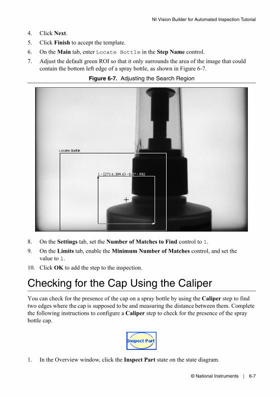
© National Instruments | 6-7
NI Vision Builder for Automated Inspection Tutorial
4. Click Next.5. Click Finish to accept the template.6. On the Main tab, enter Locate Bottle in the Step Name control.7. Adjust the default green ROI so that it only surrounds the area of the image that could
contain the bottom left edge of a spray bottle, as shown in Figure 6-7.
Figure 6-7. Adjusting the Search Region
8. On the Settings tab, set the Number of Matches to Find control to 1.9. On the Limits tab, enable the Minimum Number of Matches control, and set the
value to 1.10. Click OK to add the step to the inspection.
Checking for the Cap Using the CaliperYou can check for the presence of the cap on a spray bottle by using the Caliper step to find two edges where the cap is supposed to be and measuring the distance between them. Complete the following instructions to configure a Caliper step to check for the presence of the spray bottle cap.
1. In the Overview window, click the Inspect Part state on the state diagram.
6-8 | ni.com
Chapter 6 Branching and Decision Making
2. In the Inspection Steps palette, select the Measure Features tab.
3. Click the Caliper step. The property page for the step opens.
4. In the Step Name control, enter Check Cap Presence.5. Draw an ROI around the area in the image where a cap should appear, as shown in
Figure 6-8.
Figure 6-8. Checking for Cap Presence
6. On the Settings tab, select the Process named Horizontal Max Caliper to change the direction and orientation of the caliper search lines.
7. Set the Gap control to 10, Edge Strength to 40, and Smoothing to 12 to ensure that the step correctly detects the edges of the cap.

© National Instruments | 6-9
NI Vision Builder for Automated Inspection Tutorial
8. On the Limits tab, enable the Minimum Distance control, and set the value to 140.9. Enable the Maximum Distance control, and set the value to 160.10. Click OK to add the step to the inspection.
Setting the Inspection StatusComplete the following instructions to add a Set Inspection Status step to determine whether the inspection passes or fails.1. In the Inspection Steps palette, click the Use Additional Tools tab.
2. Click the Set Inspection Status step. The property page for the step opens.
3. In the Inspection Status control, select the Set to FAIL if any previous step fails option.4. Click OK to add the step to the inspection.
Creating Custom Overlays for InspectionUse the Custom Overlay step to create custom overlays that display whether the inspection passed or failed.
Complete the following steps to create an overlay to display when the inspection fails.
1. In the Overview window, click the Fail Part state on the state diagram.2. In the Inspection Steps palette, select the Use Additional Tools tab.
3. Click the Custom Overlay step. The property page for the step opens.
4. In the Step Name control, enter Overlay Results.
6-10 | ni.com
Chapter 6 Branching and Decision Making
5. On the Custom Overlay tab, select the Text tool and click a point in the image near the bottom of the spray nozzle of the bottle.
6. In the Text Control, enter Missing Cap!.7. Click the Text Properties button. The Text Properties dialog box opens.
8. In the Desired Font control, select User-Specified Font.9. Specify a Font Name and Size to use for the overlay.10. In the Horizontal Alignment control, select Center. This centers the text around the point
you selected using the Text tool.11. Click OK to save the Text Properties settings and close the dialog box.12. Click OK to add the step to the inspection.
Next, you need to create an overlay to display if the inspection passes. Complete the following steps to create an overlay to display when the inspection passes.
13. In the Overview window, click the Pass Part state on the state diagram.14. In the Inspection Steps palette, select the Use Additional Tools tab.
15. Click the Custom Overlay step. The property page for the step opens.16. In the Step Name control, enter Overlay Results.17. On the Custom Overlay tab, select the Rectangle tool and draw a rectangle in the
upper-left corner of the image.
18. Click the Stroke control, and select black.19. Click the Fill control, and select a bright green color.
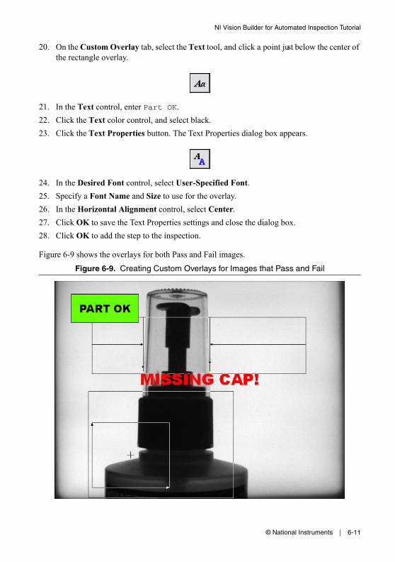
© National Instruments | 6-11
NI Vision Builder for Automated Inspection Tutorial
20. On the Custom Overlay tab, select the Text tool, and click a point just below the center of the rectangle overlay.
21. In the Text control, enter Part OK.22. Click the Text color control, and select black.23. Click the Text Properties button. The Text Properties dialog box appears.
24. In the Desired Font control, select User-Specified Font.25. Specify a Font Name and Size to use for the overlay.26. In the Horizontal Alignment control, select Center.27. Click OK to save the Text Properties settings and close the dialog box.28. Click OK to add the step to the inspection.
Figure 6-9 shows the overlays for both Pass and Fail images.
Figure 6-9. Creating Custom Overlays for Images that Pass and Fail
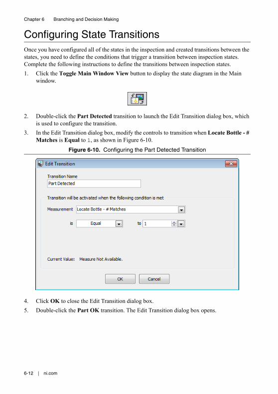
6-12 | ni.com
Chapter 6 Branching and Decision Making
Configuring State TransitionsOnce you have configured all of the states in the inspection and created transitions between the states, you need to define the conditions that trigger a transition between inspection states. Complete the following instructions to define the transitions between inspection states.1. Click the Toggle Main Window View button to display the state diagram in the Main
window.
2. Double-click the Part Detected transition to launch the Edit Transition dialog box, which is used to configure the transition.
3. In the Edit Transition dialog box, modify the controls to transition when Locate Bottle - # Matches is Equal to 1, as shown in Figure 6-10.
Figure 6-10. Configuring the Part Detected Transition
4. Click OK to close the Edit Transition dialog box.5. Double-click the Part OK transition. The Edit Transition dialog box opens.
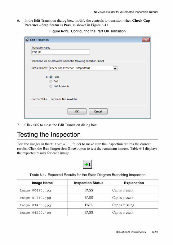
© National Instruments | 6-13
NI Vision Builder for Automated Inspection Tutorial
6. In the Edit Transition dialog box, modify the controls to transition when Check Cap Presence - Step Status is Pass, as shown in Figure 6-11.
Figure 6-11. Configuring the Part OK Transition
7. Click OK to close the Edit Transition dialog box.
Testing the InspectionTest the images in the Tutorial 5 folder to make sure the inspection returns the correct results. Click the Run Inspection Once button to test the remaining images. Table 6-1 displays the expected results for each image.
Table 6-1. Expected Results for the State Diagram Branching Inspection
Image Name Inspection Status Explanation
Image 00480.jpg PASS Cap is present.
Image 01710.jpg PASS Cap is present
Image 03450.jpg FAIL Cap is missing.
Image 04200.jpg PASS Cap is present.
6-14 | ni.com
Chapter 6 Branching and Decision Making
Saving the InspectionComplete the following instructions to save the example inspection.1. Select File»Save or click the Save button on the toolbar.
2. Navigate to the location where you want to save the inspection.3. In the File Name control, enter Tutorial 5.vbai.4. Click Save to save the inspection.
Tip Select File»Inspection Properties to add a short description or comments about the inspection.
© National Instruments | 7-1
7Looping and Variables
This chapter uses the inspection state diagram to implement a looping inspection and introduces the Set Variable and Array Operator steps. Follow the instructions in this chapter to create an inspection that inspects images of electronic components to determine if the distance between pins on the component is within a predetermined range. If the pin is too close or too far away from an adjacent pin, then the inspection fails. The inspection does not need to check every pin on the microchip before failing the inspection. The inspection fails at the first failed pin.
Note Launch Vision Builder AI if it is not open. Refer to the Vision Builder AI Configuration Interface section of Chapter 1, Introduction to Vision Builder AI, for more information.
Creating a New InspectionSelect File»New to load a new, blank Vision Builder AI inspection.
Creating the Inspection State DiagramComplete the following instructions to create a state diagram to define the inspection.1. Click the Toggle Main Window View button on the toolbar to bring the inspection state
diagram to the Main window.
2. Double-click the Inspect state to launch the Edit State Name dialog box.3. In the State Name control, enter Acquire Image & Find Pin Edges.
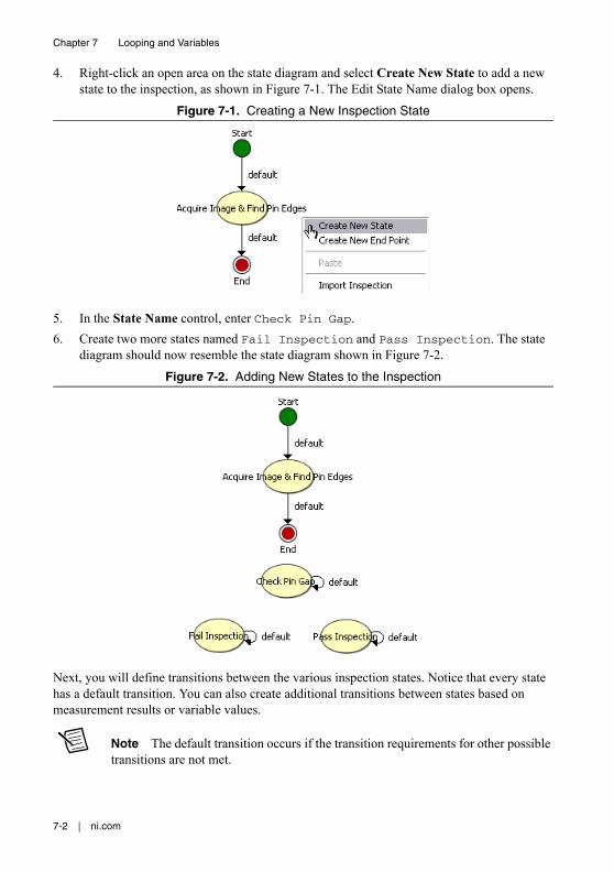
7-2 | ni.com
Chapter 7 Looping and Variables
4. Right-click an open area on the state diagram and select Create New State to add a new state to the inspection, as shown in Figure 7-1. The Edit State Name dialog box opens.
Figure 7-1. Creating a New Inspection State
5. In the State Name control, enter Check Pin Gap.6. Create two more states named Fail Inspection and Pass Inspection. The state
diagram should now resemble the state diagram shown in Figure 7-2.
Figure 7-2. Adding New States to the Inspection
Next, you will define transitions between the various inspection states. Notice that every state has a default transition. You can also create additional transitions between states based on measurement results or variable values.
Note The default transition occurs if the transition requirements for other possible transitions are not met.

© National Instruments | 7-3
NI Vision Builder for Automated Inspection Tutorial
7. Click the Acquire Image & Find Pin Edges default transition and drag it to the Check Pin Gap state.
8. Click the End point and drag it to the bottom of the state diagram.9. Click the Check Pin Gap state default transition and drag it to the Pass Inspection state.10. Click the Fail Inspection default transition and drag it to the End point.11. Click the Pass Inspection default transition and drag it to the End point.
The state diagram should now resemble the state diagram shown in Figure 7-3.
Figure 7-3. Configuring the Default Transitions
12. Right-click the Acquire Image & Find Pin Edges state and select Create New Transition.
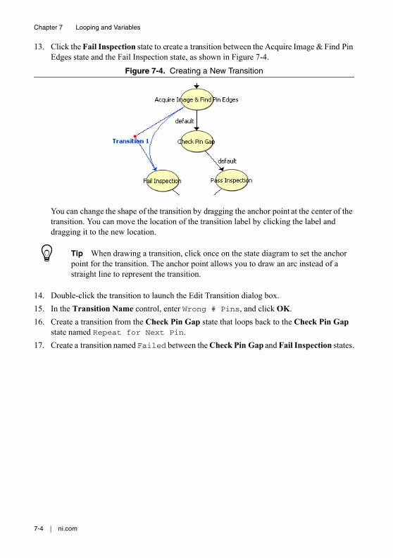
7-4 | ni.com
Chapter 7 Looping and Variables
13. Click the Fail Inspection state to create a transition between the Acquire Image & Find Pin Edges state and the Fail Inspection state, as shown in Figure 7-4.
Figure 7-4. Creating a New Transition
You can change the shape of the transition by dragging the anchor point at the center of the transition. You can move the location of the transition label by clicking the label and dragging it to the new location.
Tip When drawing a transition, click once on the state diagram to set the anchor point for the transition. The anchor point allows you to draw an arc instead of a straight line to represent the transition.
14. Double-click the transition to launch the Edit Transition dialog box.15. In the Transition Name control, enter Wrong # Pins, and click OK.16. Create a transition from the Check Pin Gap state that loops back to the Check Pin Gap
state named Repeat for Next Pin.17. Create a transition named Failed between the Check Pin Gap and Fail Inspection states.
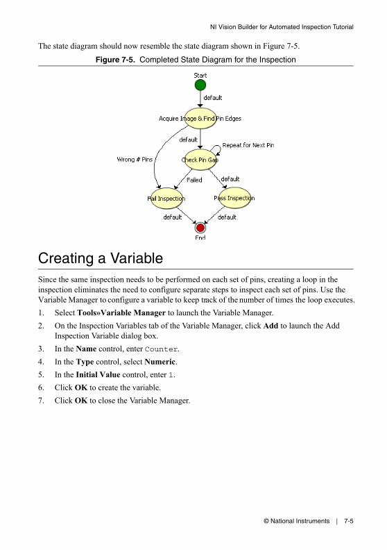
© National Instruments | 7-5
NI Vision Builder for Automated Inspection Tutorial
The state diagram should now resemble the state diagram shown in Figure 7-5.
Figure 7-5. Completed State Diagram for the Inspection
Creating a VariableSince the same inspection needs to be performed on each set of pins, creating a loop in the inspection eliminates the need to configure separate steps to inspect each set of pins. Use the Variable Manager to configure a variable to keep track of the number of times the loop executes.1. Select Tools»Variable Manager to launch the Variable Manager.2. On the Inspection Variables tab of the Variable Manager, click Add to launch the Add
Inspection Variable dialog box.3. In the Name control, enter Counter.4. In the Type control, select Numeric.5. In the Initial Value control, enter 1.6. Click OK to create the variable.7. Click OK to close the Variable Manager.

7-6 | ni.com
Chapter 7 Looping and Variables
Acquiring Inspection ImagesFor simplicity, this tutorial instructs you to use the Simulate Acquisition step. However, in your real-world inspection, use one of the other image acquisition steps to acquire images of the object under inspection.
Complete the following instructions to configure a Simulate Acquisition step that simulates acquiring images of the pins on electronic components.
1. On the state diagram, select the Acquire Image & Find Pin Edges state.2. In the Inspection Steps palette, select the Acquire Images tab.
3. Click the Simulate Acquisition step. The property page for the step opens.
Note When the property page for an inspection step opens, if the state diagram is displayed in the Main window, the state diagram switches from the Main window to the Overview window to allow you to use the current inspection image to configure the step.
4. In the Step Name control, enter Acquire Pins.5. Click the Browse button. The Select an Image File dialog box opens.
6. Navigate to <Vision Builder AI>\DemoImg\Tutorial 6, where <Vision Builder AI> is the location where Vision Builder AI is installed.
7. Select image 01.jpg, and click Open.8. Make sure the Cycle Through Folder Images control is enabled so that Vision Builder AI
loads a different simulation image from the folder each time the step is run.9. Click OK to add the step to the inspection.
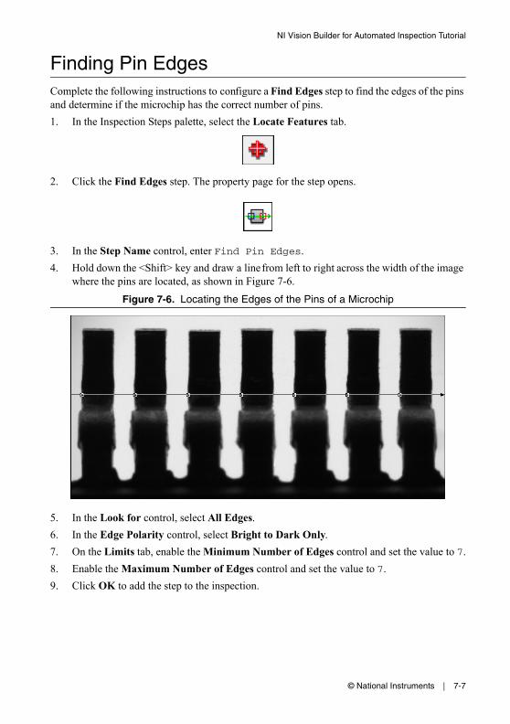
© National Instruments | 7-7
NI Vision Builder for Automated Inspection Tutorial
Finding Pin EdgesComplete the following instructions to configure a Find Edges step to find the edges of the pins and determine if the microchip has the correct number of pins.1. In the Inspection Steps palette, select the Locate Features tab.
2. Click the Find Edges step. The property page for the step opens.
3. In the Step Name control, enter Find Pin Edges.4. Hold down the <Shift> key and draw a line from left to right across the width of the image
where the pins are located, as shown in Figure 7-6.
Figure 7-6. Locating the Edges of the Pins of a Microchip
5. In the Look for control, select All Edges.6. In the Edge Polarity control, select Bright to Dark Only.7. On the Limits tab, enable the Minimum Number of Edges control and set the value to 7.8. Enable the Maximum Number of Edges control and set the value to 7.9. Click OK to add the step to the inspection.
7-8 | ni.com
Chapter 7 Looping and Variables
Initializing the VariableUse the Set Variable step to set the value of user-defined variables. Complete the following instructions to configure a Set Variable step to initialize the Counter variable.1. In the Inspection Steps palette, select the Use Additional Tools tab.
2. Click the Set Variable step. The property page for the step opens in the Main window.
3. In the Step Name control, enter Initialize Counter.4. In the Operation control, select the Set to Constant option and enter 1 for the value.5. Click OK to add the step to the inspection.
Indexing Measurements in a Result ArrayComplete the following instructions to configure an Array Operator step to index the x and y position results for the ith edge, where i is the value of the Counter variable. The position results are returned by the Find Pin Edges step in the Acquire Image & Find Pin Edges state.
1. In the Overview window, click the Check Pin Gap state on the state diagram.2. In the Inspection Steps palette, select the Use Additional Tools tab.3. Click the Array Operator step. The property page for the step opens.
4. In the Step Name control, enter Get Edge Position.5. In the Array Function list, select Index.6. In the Source Array control, select the following array elements:
• Acquire Image & Find Pin Edges»Find Pin Edges»Edge [].X Position • Acquire Image & Find Pin Edges»Find Pin Edges»Edge [].Y Position
7. In the Element Index list, select Inspection Variable - Counter.8. Click OK to add the step to the inspection.
© National Instruments | 7-9
NI Vision Builder for Automated Inspection Tutorial
In the Updating the Variable section of this tutorial, you will set the Counter variable to increment by one each time the Check Pin Gap state is run. This ensures that a different set of pins is inspected each time the Array Operator step is run.
Setting a Coordinate SystemComplete the following instructions to configure a Set Coordinate System step based on the Find Pin Edges step you configured.1. In the Inspection Steps palette, select the Locate Features tab.
2. Click the Set Coordinate System step. The property page for the step opens.
3. On the Settings tab, in the Mode control, select Horizontal Motion because the pins may shift horizontally from one image to another.
4. Click OK to add the step to the inspection.
Checking the Pin GapComplete the following instructions to measure the gap between two pins and determine if it is within a certain range.1. In the Inspection Steps palette, select the Measure Features tab.
2. Click the Caliper step. The property page for the step opens.
3. In the Step Name control, enter Measure Gap.4. Enable the Reposition Region of Interest control and verify that Set Coordinate System
is selected for the Reference Coordinate System control.
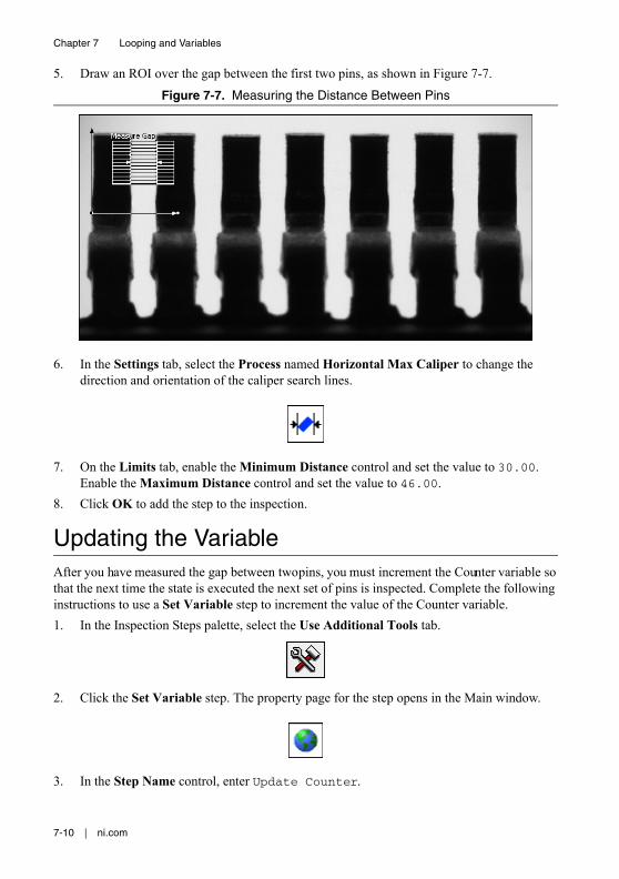
7-10 | ni.com
Chapter 7 Looping and Variables
5. Draw an ROI over the gap between the first two pins, as shown in Figure 7-7.
Figure 7-7. Measuring the Distance Between Pins
6. In the Settings tab, select the Process named Horizontal Max Caliper to change the direction and orientation of the caliper search lines.
7. On the Limits tab, enable the Minimum Distance control and set the value to 30.00. Enable the Maximum Distance control and set the value to 46.00.
8. Click OK to add the step to the inspection.
Updating the VariableAfter you have measured the gap between two pins, you must increment the Counter variable so that the next time the state is executed the next set of pins is inspected. Complete the following instructions to use a Set Variable step to increment the value of the Counter variable.1. In the Inspection Steps palette, select the Use Additional Tools tab.
2. Click the Set Variable step. The property page for the step opens in the Main window.
3. In the Step Name control, enter Update Counter.
© National Instruments | 7-11
NI Vision Builder for Automated Inspection Tutorial
4. In the Operation control, select the Increment option.5. Click OK to add the step to the inspection.
Identifying Failed PinsComplete the following instructions to create an overlay to identify a failed pin using the Custom Overlay step.1. In the Inspection Steps palette, select the Use Additional Tools tab.
2. Click the Custom Overlay step. The property page for the step opens.
3. In the Step Name control, enter Overlay Failed Gap.4. On the Custom Overlay tab, select the Indicator tool and draw a small indicator on the
image.
5. In the Top Left Point control, select Get Edge Position - Edge [i]. This aligns the top left point of the indicator overlay with the ith edge found by the Get Edge Position step.
6. In the X Offset control, enter 35. In the Y Offset control, enter 28. This positions the indicator overlay over the gap between two pins.
7. In the Value control, select Measure Gap - Step Status to set the indicator overlay to display the Step Status for the Measure Gap step in the inspection.
8. Delete the text in the True Text control since the overlay is only displayed if the inspection fails. Set the Fill to transparent.
9. In the False Text control, enter FAIL. Set the Fill to red.10. Click OK to add the step to the inspection.
7-12 | ni.com
Chapter 7 Looping and Variables
Setting the Inspection StatusComplete the following instructions to set the Inspection Status for the inspection.
1. In the Overview Window, click the Fail Inspection state on the state diagram.2. In the Inspection Steps palette, select the Use Additional Tools tab.3. Click the Set Inspection Status step. The property page for the step opens.
4. In the Step Name control, enter Set Inspection Status.5. In the Inspection Status control, select the Set to FAIL option.6. Enable the Update Number of Parts Inspected checkbox.7. Click OK to add the step to the inspection.
8. In the Overview Window, click the Pass Inspection state on the state diagram.9. In the Inspection Steps palette, select the Use Additional Tools tab.10. Click the Set Inspection Status step. The property page for the step opens.11. In the Step Name control, enter Set Inspection Status.12. In the Inspection Status control, select the Set to PASS option.13. Enable the Update Number of Parts Inspected checkbox.14. Click OK to add the step to the inspection.
Displaying the Current Inspection ImageComplete the following instructions to use a Display Image step to display the current inspection image.
1. In the Overview Window, click the Fail Inspection state on the state diagram.2. In the Inspection Steps palette, select the Use Additional Tools tab.
© National Instruments | 7-13
NI Vision Builder for Automated Inspection Tutorial
3. Click the Display Image step. The property page for the step opens.
4. In the Step Name control, enter Display Image.5. In the Display Images control, select the Always option.6. Click OK to add the step to the inspection.7. In the Overview window, click the Pass Inspection state on the state diagram.
8. In the Inspection Steps palette, select the Use Additional Tools tab.9. Click the Display Image step. The property page for the step opens.10. In the Step Name control, enter Display Image.11. In the Display Images control, select the Always option.12. Click OK to add the step to the inspection.
Configuring State TransitionsAfter you have created the state diagram and configured all of the steps in the inspection, you must specify when you want transitions from one state to another state to occur. Complete the following sets of instructions to configure the transitions for the inspection.
If an image has an incorrect number of pins, the inspection should transition to the Fail Inspection state. Complete the following instructions to define the Wrong # Pins transition.1. Click the Toggle Main Window View button on the toolbar to bring the inspection state
diagram to the Main window.
2. Double-click the Wrong # Pins transition on the state diagram to launch the Edit Transition dialog box.
3. In the Edit Transition dialog box, modify the controls to transition when Find Pin Edges - Step Status is Fail.
4. Click OK to close the dialog box.
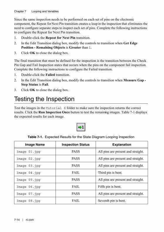
7-14 | ni.com
Chapter 7 Looping and Variables
Since the same inspection needs to be performed on each set of pins on the electronic component, the Repeat for Next Pin transition creates a loop in the inspection that eliminates the need to configure separate steps to inspect each set of pins. Complete the following instructions to configure the Repeat for Next Pin transition.1. Double-click the Repeat for Next Pin transition.2. In the Edit Transition dialog box, modify the controls to transition when Get Edge
Position - Remaining Objects is Greater than 1.3. Click OK to close the dialog box.
The final transition that must be defined for the inspection is the transition between the Check Pin Gap and Fail Inspection states that occurs when the pins on the component fail inspection. Complete the following instructions to configure the Failed transition.1. Double-click the Failed transition.2. In the Edit Transition dialog box, modify the controls to transition when Measure Gap -
Step Status is Fail.3. Click OK to close the dialog box.
Testing the InspectionTest the images in the Tutorial 6 folder to make sure the inspection returns the correct results. Click the Run Inspection Once button to test the remaining images. Table 7-1 displays the expected results for each image.
Table 7-1. Expected Results for the State Diagram Looping Inspection
Image Name Inspection Status Explanation
Image 01.jpg PASS All pins are present and straight.
Image 02.jpg PASS All pins are present and straight.
Image 03.jpg PASS All pins are present and straight.
Image 04.jpg FAIL Third pin is bent.
Image 05.jpg PASS All pins are present and straight.
Image 06.jpg FAIL Fifth pin is bent.
Image 07.jpg PASS All pins are present and straight.
Image 08.jpg FAIL Seventh pin is bent.
© National Instruments | 7-15
NI Vision Builder for Automated Inspection Tutorial
Saving the InspectionComplete the following instructions to save the example inspection.1. Select File»Save or click the Save button on the toolbar.
2. Navigate to the location where you want to save the inspection.3. In the File Name control, enter Tutorial 6.vbai.4. Click Save to save the inspection.
Tip Select File»Inspection Properties to add a short description or comments about the inspection.
© National Instruments | A-1
ATechnical Support and Professional Services
Log in to your National Instruments ni.com User Profile to get personalized access to your services. Visit the following sections of ni.com for technical support and professional services:• Support—Technical support at ni.com/support includes the following resources:
– Self-Help Technical Resources—For answers and solutions, visit ni.com/support for software drivers and updates, a searchable KnowledgeBase, product manuals, step-by-step troubleshooting wizards, thousands of example programs, tutorials, application notes, instrument drivers, and so on. Registered users also receive access to the NI Discussion Forums at ni.com/forums. NI Applications Engineers make sure every question submitted online receives an answer.
– Standard Service Program Membership—This program entitles members to direct access to NI Applications Engineers via phone and email for one-to-one technical support, as well as exclusive access to self-paced online training modules at ni.com/self-paced-training. All customers automatically receive a one-year membership in the Standard Service Program (SSP) with the purchase of most software products and bundles including NI Developer Suite. NI also offers flexible extended contract options that guarantee your SSP benefits are available without interruption for as long as you need them. Visit ni.com/ssp for more information.For information about other technical support options in your area, visit ni.com/services, or contact your local office at ni.com/contact.
• Training and Certification—Visit ni.com/training for training and certification program information. You can also register for instructor-led, hands-on courses at locations around the world.
• System Integration—If you have time constraints, limited in-house technical resources, or other project challenges, National Instruments Alliance Partner members can help. To learn more, call your local NI office or visit ni.com/alliance.
You also can visit the Worldwide Offices section of ni.com/niglobal to access the branch office websites, which provide up-to-date contact information, support phone numbers, email addresses, and current events.
© National Instruments | G-1
Glossary
C
coordinate system A reference location (origin) and angle in an image that ROIs can relate to when positional and angular adjustments of the ROI are necessary. A coordinate system is depicted by two lines representing the orientation and direction of its two axes.
D
data type A format for information. Acceptable data types for most functions are numeric, array, and string.
F
field of view The area of inspection that the camera can acquire as an image.
focal point The pixel location in a pattern matching template whose coordinates are returned as the location of a match in the inspection image.
I
inspection A vision inspection application created in and run from Vision Builder AI that can perform inline or offline visual inspections.
intensity The gray-level value of a pixel in a grayscale image.
M
match score A number ranging from 0 to 1,000 that indicates how closely an area of an acquired image matches the template image. A match score of 1,000 indicates a perfect match. A match score of 0 indicates no match.
O
object A connected region or grouping of pixels in an image in which all pixels have intensity levels in the same range.
Glossary
G-2 | ni.com
P
pattern matching The technique used to quickly locate a grayscale template within a grayscale image.
pixel Picture element—The smallest division that makes up a digital image. For measurement tasks, optimum pixel dimensions are square (aspect ratio of 1:1, or the width equal to the height).
R
resolution The number of rows and columns of pixels. An image composed of m rows and n columns has a resolution of m × n.
ROI Region of Interest—An area of the image that is graphically selected from a window displaying the image. This area can be used to focus further processing.
S
spatial calibration Assigning physical dimensions to the area of a pixel in an image.
state A particular set of steps that execute under certain conditions during an inspection.
state diagram A graphical representation of a finite state machine.
step A component of a Vision Builder AI inspection that performs a specific visual inspection task or supporting tasks, such as decision making and serial communication.
T
template Pattern that you are trying to match in an image using the Match Pattern, Match Color Pattern, Geometric Matching, or Detect Defects steps. A template can be a region selected from an image or it can be an entire image.
transition Event that causes the inspection to move from one state to another.