auto ignition, premixed & diffusive combustion in ci engines p m v subbarao professor mechanical...
TRANSCRIPT

Auto Ignition, Premixed & Diffusive Combustion in CI Engines
P M V SubbaraoProfessor
Mechanical Engineering Department
Prediction of Combustion Zones….

Four Stages of Combustion in CI Engines
-10 TC-20 10 20 30
Start ofinjection
End ofinjecction

Auto-Ignition
• One of the main issues in design of combustion systems for CI engine is to estimate the location and timing of auto-ignition that should take place in stratified-mixture conditions.
• A detailed chemistry-based auto-ignition analysis including low temperature phenomena is to be used to compute a local reaction rate of fuel.
• The premixed combustion mode is to be analyzed assuming that the reaction mechanism, which controls premixed combustion.

Auto Ignition & Premixed Combustion
• In DI Diesel engines, an equivalence ratio gradient exists across the spray volume.
• There exist a non-linear dependency for the reaction rate of fuel on equivalence ratio.
• The equivalence ratio distribution, which develops in the surrounding gas, must be considered to correctly estimate the rate of heat release by premixed combustion.
• The mean reaction rate of fuel is evaluated by an approach based on the determination of the Probability Density Function of the mixture fraction, Z {0,1}. ∈


Combustion Model
• A phenomenological diesel combustion model is composed of several sub models for fuel spray and combustion.
• Fuel spray model : Spray penetration, Air-entrainment model, and Droplet evaporation model.

Multi Zone Model for Spray at Ith Time Step
• The ignition delay for the j-th element of the spray is expressed in seconds as
RT
EpC am
jn
rid exp,
where p and T represent thpressure in MPa and the temperature in K in the cylinder. The equivalence ratio, j, is for the given element, i. The constants are chosen to be Cr=0.015 – 0.025, n= -2.0 -- -3.0 and m= -1.02 -- -1.06. The activation temperature,Ea/R, is 3500K -- 4500K.

Occurrence of Ignition delay
• It is assumed that ignition occurs when the following condition is satisfied.
11,
, ,
jig
jinj
dtjd
The integral expression accounts for the variation of pressure and temperature during the ignition delay. The suffix, inj and ig, denote the timing of fuel injection and ignition, respectively.

Premixed combustion
• It is assumed that the rate of premixed combustion is proportional to the mass of the fuel-air mixture prepared during the ignition delay period and given as
c
jmixp
p
jb mC
dt
dm
,,
l
c S
where is the Taylor microscale and Sl is the laminar flame speed.
Mmix,j is the mass of the fuel-air mixture in the given element.
Cp is an arbitrary tuning constant determined to (0.002 to 0.005) to match the test bed data.

The Taylor microscale
• The Taylor microscale is given as
21
'15
Lu
AL
where u' is the rmms value of turbulent fluctuation velocity, L is the integral length scale, and is the kinematicviscosity. The constant, A, is set to be close to unity. The integral length scale is given as
4
34/3 k
vCL where the constant, Cv, is in the range of 0.06 – 0.12.

Diffusion combustion
• Fuel-air mixing is the dominant mechanism to determine the rate of combustion during the diffusion combustion period.

• The turbulent mixing time scale is introduced to represent the rate of fuel-air mixing as,
ccac
caje
d
jb
dt
dm
dt
dm
for ,,
ccaje
d
jb
dt
dm
dt
dm
for ,,
3/12
e
e, wherem
LC
dt
dmee
je

• where mb; and me are the masses of burned fuel and entrained air in the element.
• The time scales, c and ca, denote the mixing time and the time corresponding to one degree crank angle.
• The arbitrary tuning constant, Ce, is chosen here to be 3.0 -- 5.0 X 10⁻⁵ to match the test bed data.

Post Injection Combustion
• The models during the fuel injection period may not be applicable after the end of fuel injection for the spray detached from the nozzle and moving downstream.
• The in-cylinder flow effects need to be considered to predict the combustion after the end of fuel injection.
• This is described as a mixing process with the available air at a rate controlled by turbulence in the fuel jet as,
m
e
ae,,
,
ae
je Cdt
dm
where mea is the total mass of unused air in the cylinder. The constant, Ce,a, is determined from the continuity of the combustion rate at the end of fuel injection.

Fuel Energy Distribution
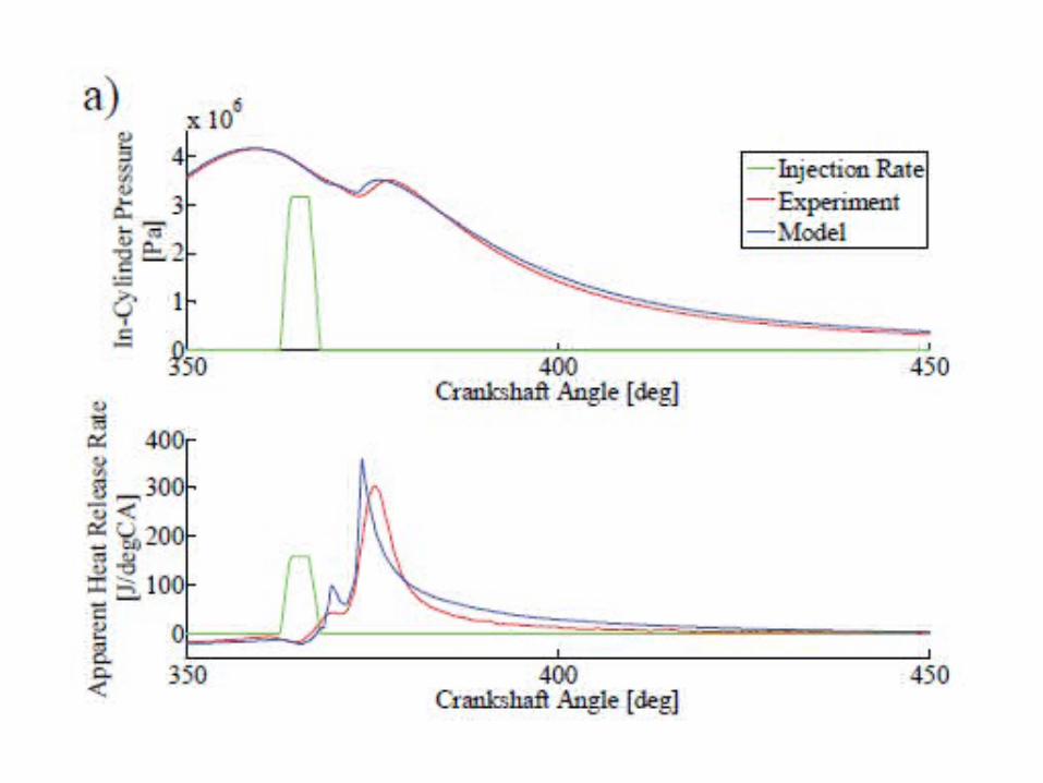
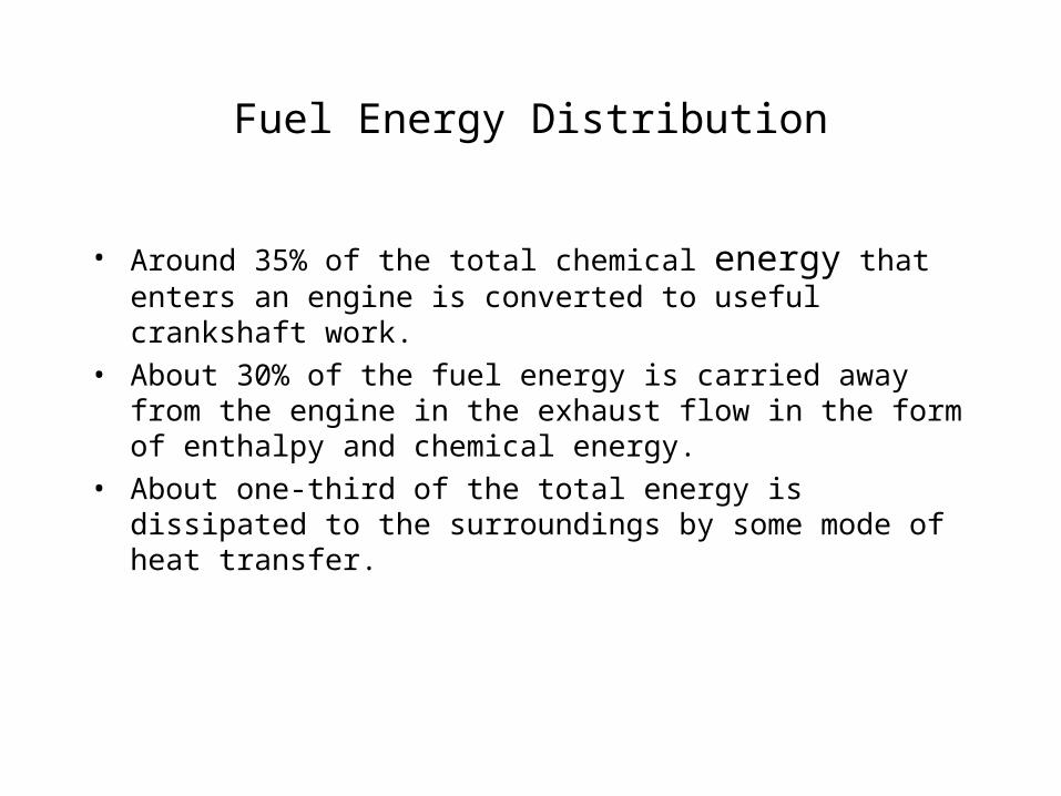
• Around 35% of the total chemical energy that enters an engine is converted to useful crankshaft work.
• About 30% of the fuel energy is carried away from the engine in the exhaust flow in the form of enthalpy and chemical energy.
• About one-third of the total energy is dissipated to the surroundings by some mode of heat transfer.

Distribution of Fuel Power
Speed, RPM