thermodynamics & gas dynamics of real combustion in turbo combustor p m v subbarao professor...
TRANSCRIPT

Thermodynamics & Gas dynamics of Real Combustion in Turbo Combustor
P M V Subbarao
Professor
Mechanical Engineering Department
Tools for precise estimation of fuel-air ratio….

Thermochemistry of Combustion

Modeling of Ideal Combustion

Modeling of Actual Combustion
LHVm
hmhmm
Δh
Δhη
fuel
in0,airex0,fuelair
ideal0,
actual0,combustor
LHVmηhmhmm fuelcombustorin0,airex0,fuelair
LHVmηhmhm fuelcombustorin0,airex0,gas
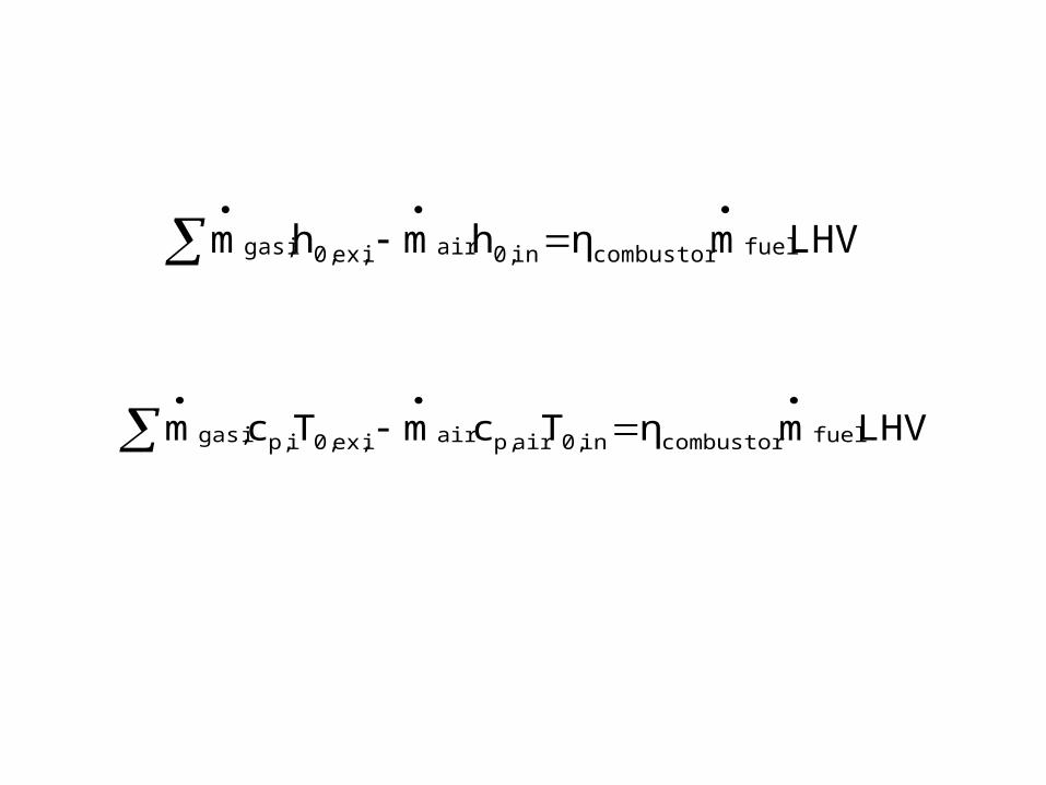
LHVmηhmhm fuelcombustorin0,airiex,0,igas,
LHVmηTcmTcm fuelcombustorin0,airp,airiex,0,ip,igas,

Modeling of Combustion
• CXHYSZ + 4.76 (X+Y/4+Z) AIR + Moisture in Air + Moisture in fuel → P CO2 +Q H2O +R SO2 + T N2 + U O2 + V CO
• Exhaust gases: P CO2 +QH2O+R SO2 + T N2 + U O2 + V CO kmols.
• Excess air coefficient : .• Emission measurement devices indicate only Dry gas volume
fractions.• Volume fraction = mole fraction or ppm• Volume fraction of CO2 : x1 = P * 100 /(P+R + T + U + V) • Volume fraction of CO : x2= VCO * 100 /(P +R + T + U + V) • Volume fraction of SO2 : x3= R * 100 /(P +R + T + U + V) • Volume fraction of O2 : x4= U * 100 /(P +R + T + U + V)• Volume fraction of N2 : x5= T * 100 /(P +R + T + U + V)• These are dry gas volume fractions.

Emission Standards
• 15% oxygen is recommended in exhaust.
• NOx upto 150 ppm.
• SO2 upto 150 ppm.
• CO upto 500 ppm.• HC upto 75 ppm.• Volume fractions of above are neglected for the
calculation of specific heat flue gas.

2222
2222222
ONOHCO
ONp,NOHp,OHCOp,COp,fluegas UMTMQMPM
cUMcTMcQMcPMc
kJ/kgK1000
T0.39
1000
T1.27
1000
T1.670.45c
32
COp, 2
kJ/kgK1000
T0.20
1000
T0.586
1000
T0.1071.79c
32
steamp,
kJ/kgK1000
T0.42
1000
T0.96
1000
T0.481.11c
32
Np, 2
kJ/kgK1000
T0.33
1000
T0.54
1000
T0.00010.88c
32
Op, 2
Specific Heat of flue gas :

LHVmηTcmTcm fuelcombustorin0,airp,airex0,p,fluegasgas-flue
•For a given mass flow rate of fuel and air, the temperature of the exhaust can be calculated using above formula.•If mass flow rates of fuel and air are known.
•Guess approximate value of specific heat of flue gas.•Calculate T0,ex.•Calculate cp,flue gase.•Re calculate T0,ex.
•Repeat till the value of T0,ex is converged.

Total Pressure Loss in Turbo Combustor
• The loss of pressure in combustor (p0,ex <p0,in) is a major problem.
• The total pressure loss is usually in the range of 2 – 8% of p0,in.
• The pressure loss leads to decrease in efficiency and power output.
• This in turn affects the size and weight of the engine. • There are several methods of quantifying the total pressure
loss in a combustor,Relative to the total inlet pressure :
in0,
ex0,in0,combustor0, p
ppΔp
Relative to the inlet Dynamic pressure :indyn,
ex0,in0,combustor0, p
ppΔp
Relative to a reference dynamic pressure:ref
ex0,in0,combustor0, p
ppΔp

Gas Dynamic Studies on Combustors
• Effect of heat generation on one dimensional ideal compressible flow.
• Effect of varying mass flow rate .• Effect of combined heat generation and friction.

Frictional Flow with Heat Transfer

Governing Equations
no body forces, viscous work negligible
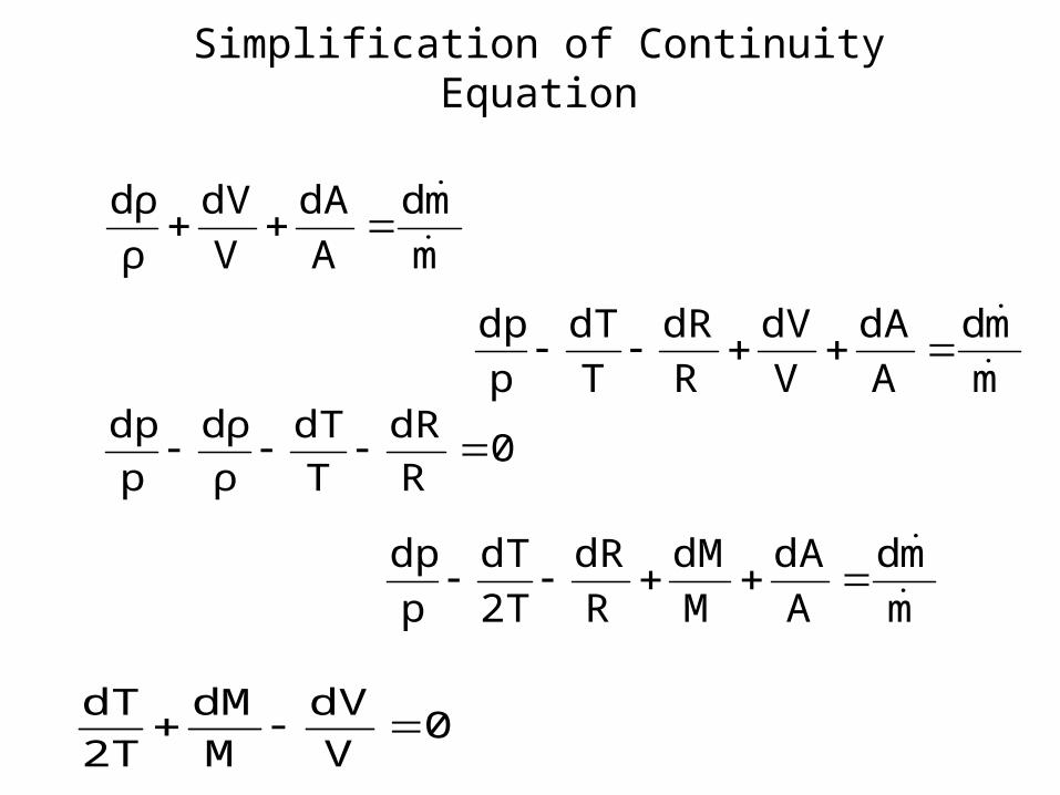
Conservation of mass for steady flow: m
md
A
dA
V
dV
ρ
dρ
Conservation of momentum for frictional steady flow :
Conservation of energy for steady flow :
0
0
p
'''2
T
dT
TC
q
V
dVM1
T
dT
δγ
0V
dVM
p
dp
D
fdxM
22
h
2 γγ

0V
dVM1
T
dT
TC
q 2
p
'''
γδ
0R
dR
T
dT
ρ
dρ
p
dpIdeal Gas law :
Mach number equation : 0V
dV
M
dM
2T
dT
m
md
A
dA
V
dV
ρ
dρ
0R
dR
T
dT
ρ
dρ
p
dp
0V
dV
M
dM
2T
dT
m
md
A
dA
V
dV
R
dR
T
dT
p
dp
m
md
A
dA
M
dM
R
dR
2T
dT
p
dp
Simplification of Continuity Equation

0V
dVM
p
dp
D
fdxM
22
h
2 γγ
0V
dV
M
dM
2T
dT
0M
dM
2T
dTM
p
dp
D
fdxM
22
h
2
γ
γ
Simplification of Momentum Equation

T
dT
TC
q
M
dM
2T
dTM1
T
dT 0
p
'''2
δγ
0M
dM
2T
dTM
A
dA
M
dM
2T
dT
R
dR
m
md
D
fdxM
22
h
2
γ
γ
0M
dM
2T
dTM
p
dp
D
fdxM
22
h
2
γ
γ
m
md
A
dA
M
dM
R
dR
2T
dT
p
dp
Combined Momentum and Continuity Equation

Constant flow rate, Constant Area, Non-reacting, Steady Compressible Flow with Friction Factor and Heat Generation
0M1TCm
Lq
D
fM
M1
M2
11
Mdx
dM 2
0p
p''
h
22
2
22
γγ
γ
Constant flow rate, Constant Area, Non-reacting, Steady Compressible frictionless Flow with Heat Generation
0M1TCm
Lq
M1
M2
11
Mdx
dM 2
0p
p''
2
2
22
γ
γ

Supersonic RAM Jets
'''0p dqdTC
Variation of Stagnation Temperature