ausforming of medium carbon steel - harry bhadeshia · pdf fileausforming of medium carbon...
TRANSCRIPT

Ausforming of Medium Carbon Steel
Seung-Woo Seo a Geun-Su Jung a Jae Seung Lee b
Chul Min Bae b H. K. D. H. Bhadeshia a,c Dong-Woo Suh a
aGraduate Institute of Ferrous Technology, Pohang University of Science and
Technology, Pohang 790-784, Republic of Korea
bTechnical Research Laboratories, POSCO, Pohang 790-785, Republic of Korea
cMaterials Science and Metallurgy, University of Cambridge, CB2 3QZ, U.K.
Abstract
The prospect of enhancing the hardness of low-alloy steel for the manufacture offasteners is examined using ausforming, in which the austenite is deformed rapidlyat a low temperature to increase its dislocation density prior to quenching in orderto obtain the harder martensite. Surprisingly small deformations accomplish largegains in hardness and the dislocation density of martensite, with diminishing returnsat larger deformations. The main contribution to the hardness has been identifiedas the extra dislocations inherited by the martensite from the deformed austenite,rather than the refinement of microstructure by the ausforming process. Clear evi-dence is reported for the mechanical stabilisation of the austenite due to ausforming.Tempering heat-treatments tend to diminish the advantages of ausforming.
Key words: ausforming, steel for fasteners, martensite, mechanical stabilisation
1 Introduction
There are essentially two domains in a time-temperature-transformation dia-gram, identified by two C-curves, the top curve corresponding to reconstruc-tive transformations and the lower one to displacive reactions. Between thesetwo C-curves, there is a range of temperatures ≈ 550 − 600 ◦C, where thetransformation of austenite takes a much longer time; as a consequence, thisregion of the TTT diagrams is often referred to as a ‘bay’. Thus, the metastableaustenite in the bay can be plastically deformed without inducing phase trans-formation, so that any martensite obtained on cooling to ambient tempera-ture has a larger defect density, is finer in scale and may be reinforced withsubstitutionally-alloyed carbides. Such a process is known as ausforming [1–
Preprint submitted to Materials Science and Technology 30 April 2014

4]. The deformation is conducted at relatively low temperatures where therecrystallisation of austenite does not occur and even recovery is minimal.
In the past, much of the work on ausforming has been conducted on richly-alloyed steels in order to obtain sufficient time within the bay to permit defor-mation. Work on low-alloy steels has involved austenite deformation at hightemperatures in the non-recrystallisation region (> 900 ◦C) [5]. However, incertain applications, such as in the production of fasteners, it is possible to im-plement rapid deformation prior to quenching. In such cases it may be feasibleto ausform low-alloy steels and gain hardness together with structural refine-ment by deformation in the bay of the TTT diagram. The advantage of thelower-temperature deformation would be to substantially enhance the hard-ness. The aim of the present work was, therefore, to investigate the ausformingof a low-alloy steel destined for the manufacture of fasteners.
2 Experimental Methods
The alloy studied is Fe-0.36C-0.74Mn-0.23Si-1.0Cr-0.21Mowt%, a cold-headingquality steel used ultimately in the quenched and tempered martensitic condi-tion. A 50 kg ingot was vacuum-melted and then hot-rolled into 30mm platewith a finishing rolling temperature above 900 ◦C. Cylindrical samples with3mm diameter and 10mm length were machined for dilatometric experimentsconducted on a Thermecmastor-Z machine made by Fuji Electronic Indus-trial Co. Ltd. The temperature that is reported from these experiments corre-sponds to measurements made at the central position along the compressionaxis, where metallographic observations and hardness measurements were alsoconducted. This mitigates the effects of any temperature variation along thelength of the sample. Austenitisation was at 880 ◦C for 60min. Fig. 1 com-pares the isothermal transformation behaviour against AISI 4140 steel whichhas similar composition [6]. There is a bay around 600 ◦C which should helpwith the ausforming process.
Ausforming was studied using 8mm diameter and 12mm length cylindricalsamples compressed at 500 or 600 ◦C on a thermo-mechanical simulator, withnominal reduction ratios of 10, 30 and 50% at a strain rate of 10 s−1, followedby quenching to obtain martensite. The samples were further tempered at550 ◦C for 90min; the metallography of these samples was conducted on thelongitudinal section. The strain analysis was conducted using the finite elementmethod implemented on ABAQUS, with materials properties of SCM435 steelwhich has a similar composition to the investigated alloy [8]. The frictioncoefficient was taken to be 0.366, evaluated from the geometry of the deformedcylinders [9].
2

Fig. 1. Time-tempera-ture-transformation diagramshowing the onset of transfor-mation. The austenitisationtemperature was 880 ◦C forthe alloy studied here and860 ◦C for the AISI 4140steel. The martensite-starttemperature was calculatedas in [7].
Vickers hardness was measured using a 1 kgf load; the quoted values representaverages of five measurements. Microstructures were observed using opticaland scanning electron microscopy (SEM) with electron back-scatter diffraction(EBSD). Samples for optical microscopy were etched using 2% nital. EBSDmeasurements required final polishing with colloidal silica in order to reduceany effects of surface deformation during sample preparation. Precipitatedcarbides were examined by transmission electron microscopy with samples ex-tracted using focused-ion beams. The dislocation density was measured usingX-ray diffraction analysis of peak broadening [10, 11], using samples chemi-cally polished in 4% HF in H2O2, which removed more than 100µm of materialfrom the surface. Monochromated CuKα radiation was used to capture the110α, 200α, 211α, 220α, 310α, and 222α peaks. Scanning was over the range2θ = 40−145◦, with a step size of 0.01956◦ and with 2 s per step. After shapecorrection, the peaks were fitted into Psudo Voight function to extractingfull-width, half-maximum (FWHM) and Fourier coefficients. The instrumen-tal effect was eliminated by Stokes method [12], then the dislocation densitywas calculated by using the modified Williamson-Hall and Warren-Averbachmethods, as described in [10].
3 Cooling curves and strain distribution
Cooling curves were recorded from samples that were made austenitic at880 ◦C, cooled to 600 ◦C at an average rate of ≈ 45 ◦Cs−1 for ausformingand then cooled to ambient temperature. The curves exhibit deviations fromfrom the general trend at temperatures below 300 ◦C, due to the latent heat ofmartensitic transformation, Fig. 2a. The martensite-start (MS) temperatureof the steel is 355 ◦C. It is evident that martensite forms at a lower tempera-ture as the nominal reduction ratio is increased, a reflection of an effect knownclassically as mechanical stabilisation [13–21]. In this, the dislocation debris
3

in the deformed austenite interferes with the passage of the transformationinterface, thus rendering it sessile. The phenomenon is associated uniquelywith displacive transformations [22] because where the transformation inter-face must be glissile in order to propagate without the need for diffusion.
Fig. 2b shows the effective strain 1 distribution on the cylinder axis along thelength of the compressed sample; it should be noted that all the metallographicobservations were made at the mid-point of the axis. The strain is naturallyconcentrated in the middle of the sample, where all of the microstructuralcharacterisations were performed. The maximum strain was 0.17, 0.7 and 1.7corresponding to the nominal reduction ratios of 10%, 30% and 50%.
4 Microstructure and hardness
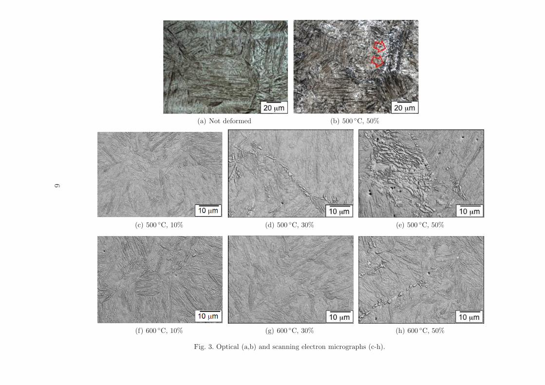
Metallographic studies have been carried out for all the samples, but the mostsignificant micrographs are presented in Fig. 3. The optical and scanning elec-tron micrographs for the sample deformed to a nominal strain of 50% at500 ◦C has a significant amount of transformation product that is not marten-site; it should be emphasised that the optical micrograph for this conditionis more representative of the amount of ferrite, whereas the scanning electronmicrograph is taken deliberately to illustrate a region containing a substan-tial quantity of ferrite (Figs 3b,c). Small amounts of ferrite could be detectedeven for the 30% strain, 500 ◦C condition (Fig. 3c) and the 50% strain, 600 ◦Csample. The results are consistent with the longer time for the initiation ofisothermal transformation at 600 ◦C (Fig. 1).
The hardness data for the untempered samples, in Fig. 4a, correlate with themicrostructural observations, with 500 ◦C ausformed samples being consis-tently softer due to the unintended isothermal transformation products in themicrostructure. However, there may be an additional factor, the occurrence ofretained austenite due to the mechanical stabilisation described earlier. Fig. 4bshows that the slight softening of the sample ausformed at 600 ◦C to a 50%nominal strain might be explained in terms of its substantial retained austen-ite content. In order to prove this conjecture, the same samples were cooledin liquid nitrogen for 10min in order to stimulate the austenite to decompose,but as can be seen from Fig. 4b, the cryogenic treatment did not result in the
1 The effective strain is given by
√2
3[(ϵ1 − ϵ2)
2 + (ϵ2 − ϵ3)2 + (ϵ3 − ϵ1)
2]1/2 (1)
where ϵi, i = 1, 2, 3 represent the principal strains calculated using the finite elementmethod.
4

(a)
(b)
Fig. 2. (a) Cooling curves for the three samples, illustrating the changes in naturalcooling when martensite forms. Two of the curves have been displaced along thehorizontal axis by adding 10 and 20 s respectively, for clarity. (b) Calculated effectivestrain as a function of the nominal compression.
decomposition of the retained austenite. It is speculated that this is becausethe plastically deformed austenite is mechanically stabilised.
In low-alloy steels the laths of martensite tend to cluster together, and areorganised hierarchically into blocks and packets within a given austenite grain[23]. A block consists of laths that are in virtually identical orientation inspace, whereas a packet is the cluster of blocks which share the same austen-ite {111} close-packed plane to which the corresponding {011} martensiteplane is almost parallel. The laths within a packet therefore have habit planeswhich make small angles with respect to each other, but have different crystal-lographic orientations. Those within blocks also have similar crystallographicorientations. It is important in the context of refinement, therefore, to reducethe block size. Figs. 5a-c show representative orientation maps for samples aus-formed at 500 ◦C, and Fig. 5d shows an example of the evaluated block widths;it is interesting that the misorientation of 60◦ between adjacent blocks is con-sistent with the literature and expectations from the common γ/α′ orientation
5
(a) Not deformed (b) 500 ◦C, 50%
(c) 500 ◦C, 10% (d) 500 ◦C, 30% (e) 500 ◦C, 50%
(f) 600 ◦C, 10% (g) 600 ◦C, 30% (h) 600 ◦C, 50%
Fig. 3. Optical (a,b) and scanning electron micrographs (c-h).
6

(a) (b)
Fig. 4. (a) Hardness data for as-quenched and ausformed samples; the temperaturesare those at which the deformation was carried out. The lower curves representdata following the tempering treatment at 550 ◦C for 90min. (b) Retained austenitecontent after quenching (line) and following cooling in liquid nitrogen (points).
relationships [24]. The influence of ausforming condition on the block width ofmartensite for all the conditions is shown in Fig. 5f. The block width becomessmaller at greater reduction ratios, similar to trends reported in the case of18Ni maraging steels even though the original block width of maraging steelis much larger [25]. In fact the mean block size at 50% nominal reduction at500 ◦C is of the order of just 1µm, a reduction by a factor of 3 when comparedwith the as-quenched martensite. It should be noted that the block sizes weremeasured on the tempered samples to ensure a high quality of orientationimaging; it is assumed that in the absence of recrystallisation, the block sizedoes not change on tempering.
The changes in hardness of the ausformed samples are shown in Fig. 4a. In bothas-quenched and tempered conditions, the martensite hardness is increasedsubstantially by the deformation of austenite. The change expected throughthe refinement of the blocks can be estimated using an equation derived herefrom experimental data on Fe-0.2C-2Mnwt% steel [26]:
σL = 723× (2L)−1/2 + 784 MPa, with HV ∼= σL ×3
9.81(2)
where L is the block width and σL the corresponding strengthening. Thelargest reduction in block size relative to the undeformed sample occurs forthe 10% nominal reduction at 500 ◦C, from about 3 to 1.5µm, with a cor-responding increase in measured hardness from 545 to 605HV, of 60HV. Incontrast, the change in hardness expected using equation 2 is only 37HV,showing that that the block size is only one of the factors influencing the in-crease in the strength of the ausformed steel. The discrepancy is most likelydue to changes in dislocation density as illustrated in Fig. 6 which shows the
7

same general trends for the sample ausformed at 600 ◦C as does the hardnessin Fig. 4. In fact the change in dislocation density from 6.08 × 10¹⁵m−2 inthe as-quenched condition, to 1.17 × 10¹⁶m−2 for the 600 ◦C 10% nominalstrain sample, is estimated using equation 14.16 of [4] to lead to an increasein hardness of 120HV. This is about 30% greater than observed (Fig. 4a), butthe inevitable conclusion is that much of the hardness change on ausformingin the present case depends on the resulting increase in the dislocation densityof the martensite.
It is seen from the present work is that even though ausforming results in sub-stantial increases in hardness, the effect is substantially reduced on temperingunder conditions appropriate for fasteners, Fig. 4a. Nevertheless, a hardnessincrease of about 50HV can be obtained using ausforming.
(a) Undeformed (b) 500 ◦C, 10% (c) 500 ◦C, 30%
(d) 500 ◦C, 50% (e) 500 ◦C, 50% (f) Block size
Fig. 5. Orientation images and corresponding data from quenched and temperedsamples. Part (e) represents measurements done across the line in (d). The blocksizes reported for the 500◦C samples may be influenced by the presence of the smallfraction of ferrite generated during ausforming.
5 Mechanical stabilisation
While the hardness results are in essence consistent with the earlier work onhigh-alloy steels [1], there are distinguishing features. Ausforming at lowertemperatures generally leads to greater hardness unless other transformations
8

Fig. 6. Dislocation densitydata for the quenched, andquenched and tempered sam-ples, measured using X-raydiffraction. (a) Lines andfilled points for samples aus-formed at 600 ◦C, (b) opencircles for those ausformed at500 ◦C; scatter bars are notpresented for this case be-cause of insufficient measure-ments.
intervene [1, 27]. However, Fig. 4a shows that the hardness of alloy ausformedat 500 ◦C is less than that at 600 ◦C following quenching to ambient temper-ature, because of the formation of ferrite during processing at 500 ◦C. Fur-thermore, the hardness increases at first as a function of the reduction ratioand then it decreases. Fig. 4b shows for the 600 ◦C condition where the struc-ture during hot-deformation retains austenite, that the amount of retainedaustenite increases with the reduction ratio, explaining the softening at largereductions.
This is a reflection of the fact that the plastic deformation of austenite can me-chanically stabilise it and reduce the amount of martensite that is ultimatelyobtained, consistent with the suppression of the martensite-start tempera-ture descried in section 3. The theory for estimating the onset of mechanicalstabilisation relies on balancing the force driving the motion of the interfaceagainst the resistance of the dislocation debris created by the deformation ofthe austenite [28, 29]. This theory can also be used to estimate quantitativelythe suppression of the MS temperature [30].
The MS temperature is calculated from the free energy change ∆Gγα′
=Gα′ − Gγ for the transformation of austenite to martensite reaching a crit-ical value ∆Gγα
MS. Plastic strain through mechanical stabilisation introduces
an additional driving force ∆GSTA needed in order for the interface to over-come the dislocation density (ρ) in the austenite, created by strain prior totransformation [28, 29]:
∆GSTA =µb
8π(1− ν)(ρ0.5 − ρ0.50 ) Jm−3
with ρ=2× 10¹³ + 2× 10¹⁴ϵ m−2 (3)
9

where µ is the shear modulus of austenite at 80GPa, b = 0.252 nm is themagnitude of the Burgers vector of the dislocations, and the Poisson’s ratioν = 0.27. The martensite–start temperature is obtained from 2
∆Gγα < ∆GγαMS
−∆GSTA (4)
The resulting calculations, together with data derived from Fig. 2 are listed inTable 1. The small stress that was maintained constant following the applica-tion of the deformation was also accounted for in the calculations as describedin [30, 31]. There is a correlation between the measured and calculated data,although the latter values are always larger. This is because the MS mea-sured from the cooling curves is dependent on the deviation from naturalcooling caused by the heat of transformation, so the first-detectable trans-formation probably corresponds to a substantial amount of transformation.But the results reinforce the conclusion regarding the mechanical stabilisationwhen martensitic transformation occurs from plastically deformed austenite.
Table 1Calculated and measured martensite-start temperatures.
Nominal % strain Effective strain Stress / MPa Measured MS / ◦C Calculated MS / ◦C
0 0 0 359
10 0.17 2 350 355
30 0.70 20 332 347
50 1.70 31 280 331
6 Transmission electron microscopy
Molybdenum carbides could not be detected in the ausformed state, eitherbecause they are very fine and difficult to image in the heavily dislocatedmartensite in the final structure, but in fact the deformation times are inthe range 0.01-0.05 s so precipitation may not be expected during ausform-ing (Fig. 7a). However, differences were found in the cementite precipitationbehaviour between the as-quenched and tempered, and as-ausformed and tem-pered structures. Fig. 7b,c show the microstructures following tempering and
2 The computer program capable of the calculations presented here can be down-loaded freely from
http://www.msm.cam.ac.uk/map/steel/programs/mucg46B.htm
10

it is evident that the cementite is finer in the sample with the nominal strainof 30%. Quantitative measurements indicated that the cementite size was re-fined from 131± 51µm to 98± 42µm on increasing the ausforming reductionfrom 10% to 30% (the size uncertainties are standard deviations in the data).This refinement of cementite particle size cannot be attributed to increaseddislocation density the difference between these two conditions is not large(Fig. 6). However, it is clear that the 30% strain sample has more intense pre-cipitation at the martensite plate boundaries. This would be precipitation tooccur followed by intragranular precipitation, because boundaries are more ef-fective nucleation sites than dislocations. As a consequence, less carbon wouldbe available for intragranular precipitation, leading to finer particle sizes.
So the question remains, why has precipitation focused on the boundaries forthe more intensely ausformed sample? When martensite forms in deformedaustenite, the structure of the α′/γ boundaries will be more imperfect thanwhen it forms in perfect austenite. This is because many of the extrinsic dislo-cations will be incorporated in the transformation interfaces, which eventuallyare halted in their progress by mechanical stabilisation. Such boundaries wouldtherefore have a higher energy and become more effective nucleation sites.
7 Conclusions
Experiments have been conducted to study the ausforming response of a low-alloy steel that is used in the manufacture of fasteners. As a result, the fol-lowing conclusions can be reached:
(1) It is possible with rapid deformation in the bay region of the time-temperature-transformation diagram, to impart sufficient deformationto the austenite without causing unwanted transformation, so that onquenching the structure obtained is substantially harder.
(2) The increase in the hardness of the martensite that grows in deformedaustenite is mainly due to an increased dislocation density, rather thanthe refinement of the microstructure.
(3) The gain in hardness and dislocation density due to ausforming is mostpronounced when the extent of deformation is just 10% in compression,with increasing deformations giving diminishing returns.
(4) There is clear evidence that deformed austenite becomes more resistantto martensitic transformation as the level of deformation is increased,both in terms of the suppression of the martensite-start temperature andthe retention of austenite.
(5) Fasteners are subjected to severe tempering following quenching; the ef-fect of this is to eliminate many of the differences between the quenched-and-tempered, and ausformed-quenched-and-tempered samples. Never-
11

theless, hardness increases of about 50HV can still be obtained relativeto samples that are not subjected to ausforming.
Acknowledgments The authors are grateful for support from the POSCO.
(a)
(b) (c)
Fig. 7. TEM of sample ausformed at 500 ◦C. (a) Quenched after ausforming to 30%nominal strain. (b) Ausformed to a nominal strain of 10%, quenched and tempered.(c) As (b) but a nominal strain of 30%.
12

References
1. D. J. Schmatz, and V. F. Zackay: ‘Mechanical properties of deformedmetastable austenitic UHS steel’, Trans. ASM, 1959, 51, 476–494.
2. W. E. Duckworth, P. R. Taylor, and D. A. Leak: ‘Ausforming behaviourof En24, En30B and an experimental 3%Cr-Ni-Si steel’, Journal of theIron and Steel Institute, 1964, 202, 135–142.
3. G. Thomas, D. Schmatz, and W. Gerberich: ‘Structure and strength ofsome ausformed steels’, In: V. F. Zackay, ed. High Strength Materials.New York, USA: John Wiley & Sons, Inc., 1965:251–326.
4. R. W. K. Honeycombe, and H. K. D. H. Bhadeshia: Steels: Microstructureand Properties, 2nd edition: Butterworths–Hienemann, London, 1995.
5. Y. Tomita: ‘Development of fracture toughness of ultrahigh strength,medium carbon, low alloy steels for aerospace applications’, InternationalMaterials Reviews, 2000, 45, 27–37.
6. H. E. Boyer, and A. G. Gray: Atlas of Isothermal Transformation andCooling Transformation Diagrams: Metals Park, Ohio, USA: ASM, 1977.
7. M. Peet, and H. K. D. H. Bhadeshia: ‘Software for transformations insteels’: http://www.msm.cam.ac.uk/map/steel/programs/mucg83.html,1982.
8. ‘JMatPro - practical software for materials proper-ties, http://www.sentesoftware.co.uk/’: 2014: URLhttp://www.sentesoftware.co.uk/.
9. Y. Li, E. Onodera, and A. Chiba: ‘Friction coefficient in hot compressionof cylindrical sample’, Materials transactions, 2010, 51, 1210–1215.
10. S. Takebayashi, T. Kunieda, N. Yoshinaga, K. Ushioda, and S. Ogata:‘Comparison of the dislocation density in martensitic steels evaluated bysome x-ray diffraction methods’, Isij International, 2010, 50, 875–882.
11. T. Ungar, and A. Borbely: ‘The effect of dislocation contrast on X-rayline broadening: A new approach to line profile analysis’, Applied PhysicsLetters, 1996, 69, 3173–3175.
12. A. R. Stokes: ‘A numerical Fourier-analysis method for the correction ofwidths and shapes of lines on X-ray powder photographs’, Proceedings ofthe Physical Society, 1948, 61, 382–391.
13. E. S. Machlin, and M. Cohen: ‘Burst phenomenon in the martensitictransformation’, Trans. Metall. Soc. AIME, 1951, 191, 746–754.
14. H. C. Fiedler, B. L. Averbach, and M. Cohen: ‘The effect of deformationon the martensitic transformation’, Transactions of the American Societyfor Metals, 1955, 47, 267–290.
15. W. C. Leslie, and R. L. Miller: ‘The stabilization of austenite by closelyspaced boundaries’, ASM Transactions Quarterly, 1964, 57, 972–979.
16. J. R. Strife, M. J. Carr, and G. S. Ansell: ‘Effect of austenite prestrainabove the Md temperature on the Ms temperature in Fe-Ni-Cr-C alloys’,Metallurgical Transactions A, 1977, 8A, 1471–1484.
17. K. Tsuzaki, S. Fukasaku, Y. Tomota, and T. Maki: ‘Effect of prior defor-
13

mation of austenite on the gamma-epsilon martensitic transformation inFe-Mn alloys’, Trans. JIM, 1991, 32, 222–228.
18. V. Raghavan: ‘Kinetics of martensitic transformations’, In: G. B. Ol-son, and W. S. Owen, eds. Martensite. Ohio, USA: ASM International,1992:197–226.
19. A. Das, P. C. Chakraborti, S. Tarafder, and H. K. D. H. Bhadeshia:‘Analysis of deformation induced martensitic transformation in stainlesssteels’, Materials Science and Technology, 2011, 27, 366–370.
20. S. M. C. van Boheman, and J. Sietsma: ‘Kinetics of martensite formationin plain carbon steels: critical assessment of possible influence of austenitegrain boundaries and autocatalysis’, Materials Science and Technology,2014, ?, DOI 10.1179/1743284714Y.0000000532.
21. A. Mangal, P. Biswas, S. Lenka, V. Singh, S. B. Singh, and S. Kundu:‘Dilatometric and microstructural response of variant selection duringmartensitic transformation’, Materials Science and Technology, 2014, ?,DOI: http://dx.doi.org/10.1179/1743284713Y.0000000487.
22. H. K. D. H. Bhadeshia: Bainite in Steels, 2nd edition: London, U.K.:Institute of Materials, 2001.
23. T. Maki: ‘Microstructure and mechanical properties of ferrous marten-sites’, Materials Science Forum, 1990, 56–58, 157–168.
24. H. Kitahara, R. Ueji, N. Tsuji, and Y. Minamino: ‘Crystallographic fea-tures of lath martensite in low-carbon steel’, Acta Materialia, 2006, 54,1279–1288.
25. I. Tamura, K. Tsuzaki, and T. Maki: ‘Morphology of lath martensiteformed from deformed austenite in 18% ni maraging steel’, Journal dePhysique Colloque, 1982, 43, 551–556.
26. S. Morito, X. Huang, T. Furuhara, T. Maki, and N. Hansen: ‘The mor-phology and crystallography of lath martensite in alloy steels’, Acta Met-allurgica, 2006, 54, 5323–5331.
27. K. S. Cho, J. H. Choi, H. S. Kang, S. H. Kim, K. B. Lee, H. R. Yang, andH. Kwon: ‘Influence of rolling temperature on the microstructure andmechanical properties of secondary hardening high Co–Ni steel bearing0.28 wt% C’, Materials Science & Engineering A, 2010, 527, 7286–7293.
28. S. Chatterjee, H. S. Wang, J. R. Yang, and H. K. D. H. Bhadeshia:‘Mechanical stabilisation of austenite’, Materials Science and Technology,2006, 22, 641–644.
29. M. Maalekian, E. Kozeschnik, S. Chatterjee, and H. K. D. H. Bhadeshia:‘Mechanical stabilisation of eutectoid steel’, Materials Science and Tech-nology, 2007, 23, 610–612.
30. H.-S. Yang, D. W. Suh, and H. K. D. H. Bhadeshia: ‘More completetheory for the calculation of the martensite-start temperature in steels’,ISIJ International, 2012, 52, 162–164.
31. J. R. Patel, and M. Cohen: ‘Criterion for the action of applied stress inthe martensitic transformation’, Acta Metallurgica, 1953, 1, 531–538.
14