assessment of pile response due to deep excavation in … ground movements during deep excavations...
TRANSCRIPT

Chinnaswamy & Chew Chiat, Cogent Engineering (2015), 2: 1014247http://dx.doi.org/10.1080/23311916.2015.1014247
CIVIL & ENVIRONMENTAL ENGINEERING | RESEARCH ARTICLE
Assessment of pile response due to deep excavation in close proximity—A case study based on DTL3 Tampines West StationC.G. Chinnaswamy1* and David N.G. Chew Chiat1
Abstract: Ground movements during deep excavations and tunnelling, especially in urban areas, may potentially have major impact on adjacent buildings, struc-tures and utilities. This impact on buildings and structures needs to be assessed by considering the horizontal and vertical displacements induced by deep excavations to determine the necessary mitigation measures. One major factor affecting the degree of severity the impact due to deep excavation may have on the buildings and structures is the type of foundation systems. While methodology in determining the damage category for the buildings on shallow foundation has been quite well established, the methodology for assessing the impact on the pile foundation is not straightforward due to the geometry and complexity of soil structure interaction. Often simplified two-dimensional (2D) or comprehensive three-dimensional (3D) finite element analyses would be carried out for the stage excavation to predict the displacement and stresses in the piles. Suitable protective and preventive measures would need to be designed and implemented for the existing buildings/structures if the damage category falls within the unacceptable range. This paper discusses the analysis and methodology to assess the effect on the pile foundation of a high-rise building due to the deep excavation of the Down Town Line Stage 3 (DTL3) Tampines West (TPW) Station. The approach to assess the geotechnical capacity of the pile as a result of the deep excavation is presented in this paper. Based on the assessment
*Corresponding author: C.G. Chinnaswamy, Meinhardt Infrastructure Pte Ltd, Singapore, SingaporeE-mail: [email protected]
Reviewing editor:Gang Zheng, Tianjin University, China
Additional information is available at the end of the article
ABOUT THE AUTHORC.G. Chinnaswamy completed his PhD from IIT Delhi in 1988 and continued his postdoctoral studies in Colorado University, Boulder, CO, USA in 1991. He has 25 years of industrial experience in infrastructure projects across many countries. He has published more than 25 papers in referred journals, conferences and symposiums. His key research areas are non-linear finite element analysis, iterative and multigrid solvers mesh generation, slope stability, 3D CAD-CAE, geostatistical interpolation, etc. Currently, he is developing of a novel algorithm for accurate determination of non-circular slope failure profile in CAD.
PUBLIC INTEREST STATEMENTThe assessment of construction impact due to tunnelling and underground excavations on the existing structures/buildings, especially in urban areas, is of prime importance and the stagewise assessment procedure is briefly covered in this paper. In that process, behaviour of piles supporting these adjacent buildings has also been studied. Any pile, being close to the retaining system for a deep excavation, will be subjected to reduction in mobilized effective normal pressure on the pile and thus the shaft friction, which of course depends upon on its distance away from the retaining system, pile toe level with respect to the final excavation level, etc. Considering the overall force equilibrium, this reduction in shaft friction will be distributed to soil around the pile toe or adjacent row of piles.
Received: 02 September 2014Accepted: 25 January 2015Published: 20 March 2015
© 2015 The Author(s). This open access article is distributed under a Creative Commons Attribution (CC-BY) 4.0 license.
Page 1 of 16
C.G. Chinnaswamy
Page 2 of 16
Chinnaswamy & Chew Chiat, Cogent Engineering (2015), 2: 1014247http://dx.doi.org/10.1080/23311916.2015.1014247
of pile response, predicted movement, structural and geotechnical capacities of the pile, it was found to be within the acceptable limit and the pile foundation has adequate factor of safety with the deep excavation in close proximity.
Subjects: Civil, Environmental and Geotechnical Engineering; Geomechanics; Soil Mechanics; Tunnelling & Underground Engineering
Keywords: underground excavation; damage assessment; prediction of pile behaviour; numerical analysis
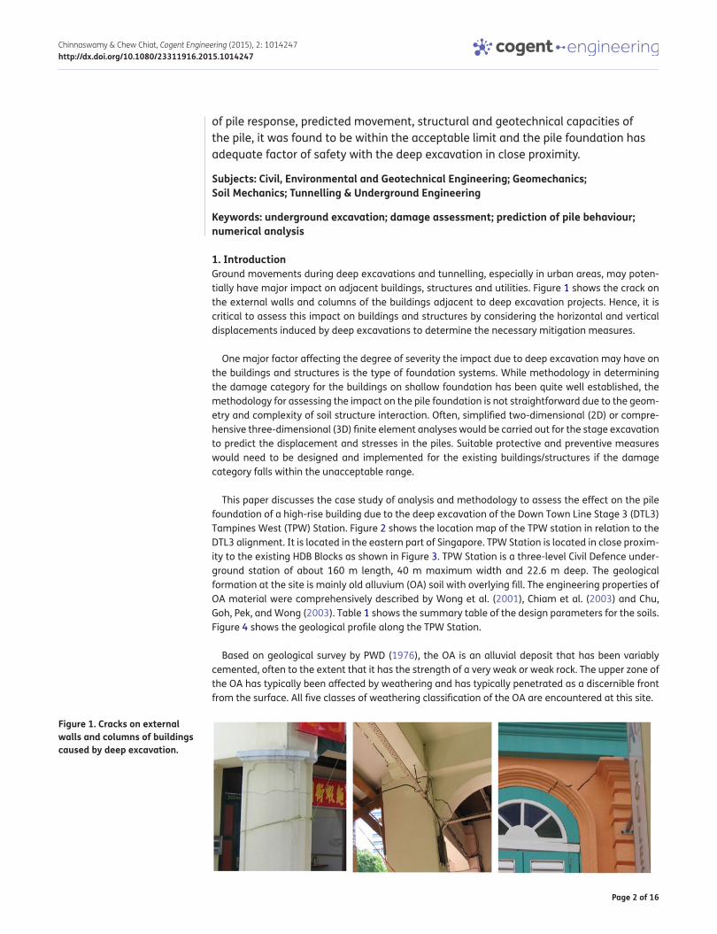
1. IntroductionGround movements during deep excavations and tunnelling, especially in urban areas, may poten-tially have major impact on adjacent buildings, structures and utilities. Figure 1 shows the crack on the external walls and columns of the buildings adjacent to deep excavation projects. Hence, it is critical to assess this impact on buildings and structures by considering the horizontal and vertical displacements induced by deep excavations to determine the necessary mitigation measures.
One major factor affecting the degree of severity the impact due to deep excavation may have on the buildings and structures is the type of foundation systems. While methodology in determining the damage category for the buildings on shallow foundation has been quite well established, the methodology for assessing the impact on the pile foundation is not straightforward due to the geom-etry and complexity of soil structure interaction. Often, simplified two-dimensional (2D) or compre-hensive three-dimensional (3D) finite element analyses would be carried out for the stage excavation to predict the displacement and stresses in the piles. Suitable protective and preventive measures would need to be designed and implemented for the existing buildings/structures if the damage category falls within the unacceptable range.
This paper discusses the case study of analysis and methodology to assess the effect on the pile foundation of a high-rise building due to the deep excavation of the Down Town Line Stage 3 (DTL3) Tampines West (TPW) Station. Figure 2 shows the location map of the TPW station in relation to the DTL3 alignment. It is located in the eastern part of Singapore. TPW Station is located in close proxim-ity to the existing HDB Blocks as shown in Figure 3. TPW Station is a three-level Civil Defence under-ground station of about 160 m length, 40 m maximum width and 22.6 m deep. The geological formation at the site is mainly old alluvium (OA) soil with overlying fill. The engineering properties of OA material were comprehensively described by Wong et al. (2001), Chiam et al. (2003) and Chu, Goh, Pek, and Wong (2003). Table 1 shows the summary table of the design parameters for the soils. Figure 4 shows the geological profile along the TPW Station.
Based on geological survey by PWD (1976), the OA is an alluvial deposit that has been variably cemented, often to the extent that it has the strength of a very weak or weak rock. The upper zone of the OA has typically been affected by weathering and has typically penetrated as a discernible front from the surface. All five classes of weathering classification of the OA are encountered at this site.
Figure 1. Cracks on external walls and columns of buildings caused by deep excavation.

Page 3 of 16
Chinnaswamy & Chew Chiat, Cogent Engineering (2015), 2: 1014247http://dx.doi.org/10.1080/23311916.2015.1014247
2. Stagewise damage assessmentDamage assessment of buildings or structures adjacent to deep excavations is a major design con-sideration in densely built-up areas. These excavations are designed with earth retaining and stabi-lizing structures (ERSS), which must be robust enough to prevent and minimize any damage to the adjacent structures. It is necessary to predict the extent of ground movements that may cause damage to the structures. For buildings and structures on pile foundations, the following steps are part of the damage assessment procedure:
(1) Predicting the vertical and horizontal movements of building and foundations which are deter-mined from the numerical analysis by considering the foundation contribution in the continuum model or by empirical methods using Gaussian Settlement curve for the case of bore tunnelling works.
(2) Damage assessment of the structure based on the predicted vertical and horizontal move-ments and assuming greenfield conditions with buildings as masonry structures.
(3) Study on pile behaviour and response based on the reduction in pile skin friction due to change in stress-field in soil and thus the impact on the geotechnical capacity of the pile. The addi-tional pile displacements, bending moments and shear forces induced on the pile due to the excavation would also be studied.
A case study based on DTL3 C926 TPW Station deep excavation effect on the adjacent pile founda-tion for a high-rise building is presented in the following sections. In general, the damage assess-ment procedure as described in Step 2 above for buildings and structures are carried out in three stages, Stages I–III which are discussed in the following paragraphs.
Stage I assessment is a preliminary assessment based on the allowable settlement or rotation according to CIRIA PR 30 (1996). If the predicted settlement contours shows more than 10 mm at the building location or if the settlement gradient is more than 1/500, the building or structure should be subjected to Stage II assessment. The predicted settlement is not only due to ERSS’s direct deformation effect, but also the settlement due to ground water draw-down and consolidation set-tlement in case of clayey soils overlying highly pervious soils. Figure 5 shows the settlement contour around the TPW Station due to deep excavation. HDB Blocks No. 802, 803 and 933 fall within the settlement zone of more than 10 mm. Hence, they are subjected to Stages II and III of the damage assessment procedure.
Figure 2. Location map for DTL3 C926 TPW Station.
C926 TPW Station

Page 4 of 16
Chinnaswamy & Chew Chiat, Cogent Engineering (2015), 2: 1014247http://dx.doi.org/10.1080/23311916.2015.1014247
Figu
re 3
. Pla
n sh
owin
g pr
oxim
ity o
f the
TPW
Sta
tion
to th
e HD
B Bl
ocks
.

Page 5 of 16
Chinnaswamy & Chew Chiat, Cogent Engineering (2015), 2: 1014247http://dx.doi.org/10.1080/23311916.2015.1014247
Table 1. Summary table of soil parametersMaterial Unit
weight (kN/m3)
Strength parameters Undrained modulus, Eu
(MN/m2)
Drained Modulus,
E′ (MN/m2)
Coefficient of earth pressure
at-rest, Ko
Permeability (m/s)Total stress Effective stress
Su (kN/m2)
c′ (kN/m2)
φ′ (o)
Fill 20 30 0 – – 8.7 0.5 10−7
E 15 0.75z + 16.25 (20 ≤ Su ≤ 35)
0 15 0.2Su EU/1.2 1.0 10−9
F1 20.5 – 0 30 – 8.7 0.7 10−5
F2 19 1.5z + 12.5 (20 ≤ Su ≤ 50)
5 25 0.2Su EU/1.2 1.0 10−9
M 16 1.285z + 3.575 for 10≤
Su ≤55
0 22 0.3Su EU/1.2 1.0 10−9
Old Alluvium
OA (E) (N < 10) 20 5 N 0 30 1.0 EU/1.2 10−7
OA (D) (10 ≤ N < 30) 20 5 N 5 32 2 N EU/1.2 10−7
OA (C) (30 ≤ N < 50) 21 5 N 10 32 2 N EU/1.2 0.7(5) 10−7
1.0
OA (B) (50 ≤ N < 100) 21 3 N + 100 10 35 1.2 N + 40 EU/1.2 10−7
OA (A) (N ≥ 100) 21 400 20 35 160 EU/1.2 10−7
Figure 4. Geological profiles along TPW Station.

Page 6 of 16
Chinnaswamy & Chew Chiat, Cogent Engineering (2015), 2: 1014247http://dx.doi.org/10.1080/23311916.2015.1014247
Stage II assessment is based on limiting tensile strain approach adopted by Burland and Wroth (1974), Boscardin and Cording (1989) and Burland (1997, 2008), where the building is idealized as an equivalent deep beam of length, L and height H as shown in Figure 6, with an assumption that the building follows the settlement trough and also the lateral movements induced by deep excavation works as in Figure 7.
The deflection ratio, h/lh and s/ls, where suffix “s” is for sagging and “h” is for hogging, is a measure of curvature and various induced strains viz., maximum extreme fibre strain, b(max) (bending), maxi-mum diagonal strain, d(max) (shear) and their respective resultants, εbr and εdr when combined with horizontal strain, h. The procedure to estimate various strains is well described in publications of Burland (2008) and Loganathan (2011).
The maximum induced strain among these resultant strains is set as the limiting tensile strain, εlim and a range in the limiting tensile strain is used to categorize the damage to the building from being at “Negligible” through to “Very Severe” risk as shown in Table 2. Description of typical damage according to degree of severity with particular reference to ease of repair of plaster and brickwork or masonry can be seen from references by Burland (2008), Civil Design Criteria of LTA (2008), and Loganathan (2011).
Stage III assessment is a detail assessment of the structures with numerical analyses. In general, all structures that have been classified in the “Moderate” or higher damage risk categories during Stage II assessment are classified as “Sensitive Structures”. However, historical and sensitive struc-tures with a “Slight” damage category and any structures on pile and mixed foundations will also be subjected to Stage III assessment according to LTA Civil Design Criteria (2008). The Stage III assess-ment can be performed by using either the method proposed by Potts and Addenbrooke (1996) or using numerical modelling by incorporating the building stiffness as well. In addition, all reinforced concrete structures will be assessed based on their service-ability limits. Two-dimensional analyses are usually carried out instead of 3D analyses due to the complexity of the 3D modelling procedures. While selecting the 2D numerical approach for Stage III assessment, the following factors should be kept in view:
Figure 5. Settlement contour around TPW Station due to deep excavation.

Page 7 of 16
Chinnaswamy & Chew Chiat, Cogent Engineering (2015), 2: 1014247http://dx.doi.org/10.1080/23311916.2015.1014247
• Since piles are discrete elements, smearing of pile stiffness should be suitably considered.
• If as-built information is not suitable like pile length, geophysical survey to ascertain the pile length and a set of parametric study needs to be carried out for a possible range of pile lengths to make it reasonably conservative.
3. Assessment of impact on pile foundation by numerical analysesThis section will discuss the numerical analyses aimed to check for the changes in geotechnical pile capacities which are quite likely to happen due to the settlements and changes in stress field in the soil surrounding the piles due to wall deflection and base heave during excavation. This stress field changes will lead to a reduction in the effective normal stress and thus the skin friction on the piles, which in turn will increase in end bearing pressure. These changes need to be checked for the ulti-mate end bearing capacity of the pile. The typical section of ERSS for TPW station adjacent to the HDB Block 803 is as shown in Figure 8.
Figure 6. Building idealization for Stage II damage assessment.
Figure 7. Building deformation—partitioning between sagging and hogging.
Table 2. Relationship between category of damage and limiting tensile strainCategory of damage Normal degree of severity Limiting tensile strain, εlim (%)0 Negligible 0–0.05
1 Very slight 0.05–0.075
2 Slight 0.075–0.15
3 Moderate 0.15–0.3
4 and 5 Severe to very severe >0.3

Page 8 of 16
Chinnaswamy & Chew Chiat, Cogent Engineering (2015), 2: 1014247http://dx.doi.org/10.1080/23311916.2015.1014247
Figu
re 8
. Typ
ical
sec
tions
of E
RSS
for T
PW s
tatio
n ad
jace
nt to
the
HDB
Bloc
k 80
3.

Page 9 of 16
Chinnaswamy & Chew Chiat, Cogent Engineering (2015), 2: 1014247http://dx.doi.org/10.1080/23311916.2015.1014247
For a typical case of piles supporting 9-storey HDB Blocks No. 803 and 933 adjacent to deep exca-vation for TPW Station, the finite element model is shown in Figure 9. This model is a 2D plane strain model with 15 noded isoparametric triangular elements for soil layers and 5 noded plate elements for all structural elements except for struts for which node-to-node anchor elements/plane truss element were adopted. The piles were also modelled as plate elements with their stiffnesses smeared for the average pile spacing and the soil–pile interaction was modelled by using the interface elements around the pile elements which were assigned with reduced soil strength properties (decreased by a strength reduction factor, Rf). In the stress analysis, both x and y displacements were set to zero at the bottom boundary, whereas at the truncated sides, only nodal displacements in the x-direction were set to zero.
The soil constitutive model used in the analysis was the Mohr–Coulomb model, an elastic perfectly plastic bilinear stress strain model. Undrained behaviour was set for all clay layers by choosing und-rained material type, undrained elastic modulus, Eu, and undrained strength parameters of Su and Φu = 0 and drained behaviour was set with drained material type, effective elastic modulus, E′ and effective stress parameters viz, c′ and φ′ for all sandy soils. However, since OA soil behaviour is in the transition between drained and undrained behaviour, both these cases were considered thus leading to two sets of numerical analyses covering drained and undrained cases. In all cases of numerical analyses, pore water pressure of soil elements was determined by a steady-state 2D seepage analy-sis which was carried out prior to elasto–plastic stress analysis for each excavation/construction stage. Calculated pore water pressures in this way were used for the effective stress calculations and then used in the elasto–plastic analysis.
The pile foundation for the HDB Block No. 803 and 933 consists of 700 mm diameter bored piles at approximately 3.5 m centre-to-centre spacing. The lengths of the piles were not available in the as-built drawings retrieved from BCA. Initial estimate of the piles was based on the estimated working load from the columns. Later, geophysical survey was carried out to verify the estimated pile length. Finally, pile length of 18 m was adopted in the analyses and study. For ERSS design, Sandi, Shen, Leung, Liew, and Kho (2007) compared 2D and 3D FE analyses with field measurements and a range of smear-ing factors to be adopted in 2D FE analysis and concluded that using smearing factor of 3dpile gives similar predictions using 3D numerical analysis. In 2D analyses, we adopt a smearing effect for the discrete structural elements like piles to simulate the discrete element using 2D plane strain analysis.
Figure 9. Finite element meshes showing the pile foundation arrangement adjacent to a deep excavation (encircled closest pile considered in this study).

Page 10 of 16
Chinnaswamy & Chew Chiat, Cogent Engineering (2015), 2: 1014247http://dx.doi.org/10.1080/23311916.2015.1014247
4. Results of numerical analysesFigures 10 and 11 show the vertical and horizontal soil displacements, respectively, for the complete cycle of excavation and backfill. As shown in Figure 10, the downward displacement on both sides of the plate element, which represents the pile, is unsymmetrical. The vertical downward displacement on the side nearer to the excavation is larger than the vertical downward displacement on the other side further away from the excavation. This has resulted in the unsymmetrical changes in the shear stress on both sides of the plate element. This will be discussed in more detail in Section 5 of this paper. On the other hand, as shown in Figure 11, the horizontal displacement of the soil on the side of the plate element is almost similar. This is due to the reason that the pile element has been mod-elled as a thin plate element and thus has not caused any significant change in the stress field and vertical movement of the soil on both sides of the plate element. This has resulted in symmetrical decrease in the normal stress on the plate element.
Figure 10. Vertical soil displacements due to the complete cycle of stage excavation and construction of the station structure.
Figure 11. Horizontal soil displacements due to the complete cycle of stage excavation and construction of the station structure.

Page 11 of 16
Chinnaswamy & Chew Chiat, Cogent Engineering (2015), 2: 1014247http://dx.doi.org/10.1080/23311916.2015.1014247
5. Reduction in skin friction resistance of the pileFor the pile close to the deep excavation, comparison of effective normal stress distribution on the pile shaft before and after excavation is shown in Figure 12. The kinks especially at elevations closer to the ground levels seen at the plot of effective normal stress after excavation are due to the pre-loading effect. The resultant of the normal stress on pile interfaces both on soil side and excavation side is same. However, the resultant of the normal stress before the excavation is 1,155 kN/m, whereas after excavation, it reduces to 878 kN/m, which is about 24% reduction from the value be-fore excavation. The response of pile in terms of the normal stress acting on the pile is almost sym-metrical due to the reason that the pile has been modelled as a plate element with smeared properties of the pile. This thin plate element has caused insignificant change in the stress field on both sides of the plate due to the low stiffness. In addition, the results also indicate that there is no build up of active and passive soil pressure on the two sides of plate element when soil movement occurred. This is likely due to the low stiffness of the plate element.
In the conventional method of checking the geotechnical capacity of bored pile, empirical rela-tionship, fs = Ks × N is commonly used to determine the ultimate skin friction, where N = SPT values and the coefficient, Ks, varies from 1.5 to 2.5 for stiff-to-hard cohesive soils, including Bukit Timah Granite and Jurong formation soils and 2–3 for dense and hard, cemented OA soils. For both the cases, the limiting values of fs are specified CP04:200 as 150 and 300 kPa respectively. Similar way of estimating the ultimate end bearing from the SPT-N values is also described in CP 04:2003 (2003). While adopting this empirical method for estimating the pile’s ultimate geotechnical capacities, the same reduction factor for the skin friction due to adjacent deep excavation can be applied in order to include the effect of adjacent deep excavation on ultimate skin friction of the piles.
Comparison of developed skin friction on the both sides of the plate elements which simulate the pile shaft before and after excavation is shown in Figure 13. The sign convention for the representa-tion of the graphs is positive for upward direction shear stress and negative for downward direction shear stress for the face near to excavation and is negative for upward direction shear stress and positive for downward direction shear stress for the face away from excavation. The shear stress
Figure 12. Effective normal stress distribution on the pile closest to the excavation before and after excavation.

Page 12 of 16
Chinnaswamy & Chew Chiat, Cogent Engineering (2015), 2: 1014247http://dx.doi.org/10.1080/23311916.2015.1014247
distribution on the two sides of the plate element of the pile before excavation is both showing upward direction but is unsymmetrical. The unsymmetrical distribution is due to the reason that the pile is on the edge of the series of piles for the building.
After excavation, there is soil movement towards the excavation and also subsurface soil settle-ment. The resulting soil movement due to the excavation is such that there is also similar change in the horizontal displacement on both sides of the plate element and there is more downward dis-placement of the soil on the side of the plate element closer to excavation than the other face away from excavation. As a result of this soil movement, there is an increase in the upward shear stress on the face of the plate element away from the excavation, while there is a decrease in the upward shear stress and increase in downward shear stress on the face of the plate element near to the excavation. This is likely to be caused by the settlement of the subsoil layers and induces negative skin friction on the pile. The effect of the change in shear stress acting on the pile on its end bearing pressure and overall geotechnical capacity is discussed in more detail in Sections 6 and 7.
6. Increase in end bearing pressure of the pileIn order to maintain the force equilibrium condition, the reduction in skin friction will obviously lead to increase in pile axial force and thus the pile end bearing pressure. Figure 14 shows the pile axial force variation with depth. Before excavation, the axial force is 112 kN/m at the toe of the plate ele-ment. After excavation, the axial force at the toe of the plate element increases to 275 kN/m due to the increase in down drag of the soil as a result of settlement. Assuming that the displacements and stress field changes in the soil due to deep excavation would not change the bearing capacity of the soil, it is necessary to check whether this greater end bearing pressure is within the allowable end bearing capacity of the soil layer at the pile toe level. The assessment of pile geotechnical capacity will be described in Section 7.
7. Assessment of pile structural and geotechnical capacityFor the pile structural capacity, it has been checked using the bending moment and shear force dia-gram obtained from the analyses and multiplied with the smearing factor and found to be accept-able. The details for the structural capacity check is not included in this paper as it is a straightforward
Figure 13. Comparison of development of skin friction on the pile closest to the excavation before and after excavation.

Page 13 of 16
Chinnaswamy & Chew Chiat, Cogent Engineering (2015), 2: 1014247http://dx.doi.org/10.1080/23311916.2015.1014247
procedure and commonly used by engineers. This section will focus on the assessment of geotechni-cal capacity of the pile as a result of the ground movement caused by deep excavation of TPW Station, which is important to ensure the safety of the building but not commonly checked by engi-neers probably due to the difficulties in interpreting the results from the analyses and understanding the response of the pile before and after excavation.
Table 3 shows the comparison of the pile shaft friction and factor of safety for the cases before and after excavation. The total mobilized skin friction per pile is calculated by multiplying the total shear stresses along the plate element on both faces by the smearing factor. The total mobilized skin friction was reduced from 1,004.5 to 490 kN. The average skin friction is obtained by dividing the total skin friction by the shaft area. The average skin friction is reduced from 30.6 to 15 kPa. After the excavation, the soil has been disturbed along the pile. The load transfer from the pile to soil will
Figure 14. Variation of pile axial force with depth at the pile closest to the retaining wall before and after excavation.
Table 3. Summary table of comparison of pile shaft friction and factor of safety for the cases before and after excavationDeveloped skin friction Before excavation After excavationSkin friction mobilized 287 kN/m 140 kN/m
Skin friction per pile 287 × 3.5 kN 140 × 3.5 kN
=1,004.5 kN =490 kN
Average skin friction pressure 1,004.5/shaft area 490/shaft area
=1,004.5/32.8 =490/32.8
=30.6 kPa =15 kPa
Ult skin friction (2.5 N) = 125–250 kPa (Average SPT values are in
the range of 50–100)
Shaft friction will be disturbed after excavation

Page 14 of 16
Chinnaswamy & Chew Chiat, Cogent Engineering (2015), 2: 1014247http://dx.doi.org/10.1080/23311916.2015.1014247
be redistributed. The reduction in the shaft resistance will be compensated by the increase in the end bearing resistance. Hence, it is not necessary to evaluate the factor of safety of the pile in terms of shaft friction.
Table 4 shows the comparison of the pile end bearing and factor of safety for the cases before and after excavation. The end bearing force was obtained from the axial force at the toe of the plate ele-ment multiplied with the smearing factor. The end bearing force increases from 420 kN per pile be-fore excavation to 963 kN per pile. This is corresponding to the increase of end bearing pressure on the soil from 1,010 to 2,502 kPa. The end bearing pressure is obtained by dividing the end bearing force per pile by the pile base area. The SPT-N value for the soil at the toe level of the pile is approxi-mately 80. Based on the SPT-N value of 80 and limiting end bearing pressure, Fb = 60 N, the limiting end bearing pressure is 4,800 kPa. Thus, the factor of safety of the pile in terms of end bearing is adequate.
The above assessment for the geotechnical capacity of the pile has considered the increase in end bearing pressure of the piles predicted as by the analyses, and has calculated the factor of safety in terms of end bearing for the piles as a result of the station excavation. These show that the factor of safety is still sufficient to meet the minimum requirement.
Before the station is constructed, the piles will have a working load W applied at the pile head. This will be almost entirely resisted in skin friction as the OA strata are highly competent and the piles would predominantly be friction piles. The end bearing pressure at the base of the piles will be very small. During station excavation, there will be some relatively small deformations of the ground outside the diaphragm walls. As a result, the piles are likely to settle by a small amount and this will cause some redistribution of the friction and end bearing components of the pile load, with some increase in end bearing and a corresponding reduction in skin friction. However, the ultimate pile capacity has not been reduced. At the end of the station construction, the same working load W is applied to the pile (assuming no redistribution of load between adjacent piles); this is still resisted mainly by skin friction and by an increased amount of end bearing. The pile will have the same ulti-mate capacity. The only change is that the pile will simply have settled by a small amount, and there will have been a redistribution of the friction and end bearing components resisting the original pile working load.
Table 5 shows the summary table of the assessment of the pile. The pile lengths of 18 m have been considered for Blocks 803 and 933. In view of the uncertainty due to the unavailability of as-built information for the pile foundation, geophysical testing was essential to verify the assumed pile length. As the ground conditions are principally OA, the piles are acting as predominantly friction piles, with little or no load acting on the pile base. This means that the pile was mainly resisted by friction and has little resistance from end bearing in the original state. After excavation, the pile load transfer to soil merely change its path from via shaft friction to via end bearing at toe.
Table 4. Summary table of comparison of pile shaft friction and factor of safety for the cases before and after excavationDeveloped end bearing pressure
Before excavation After excavation
End bearing force/m 112 kN/m 275 kN/m
End bearing forces/pile 112 × 3.5 = 420 kN 275 × 3.5 = 963 kN
Developed end bearing pressure 392/pile area = 1,018 kPa 963/pile area = 2,502 kPa
Ultimate end bearing Based on N = 80 and Fb = 60 N Based on N = 80 and Fb = 60 N
Fb = 4,800 kPa Fb = 4,800 ka
FOS (end bearing) 4.7 (minimum and based on N = 80)
1.9 (minimum and based on N = 80)

Page 15 of 16
Chinnaswamy & Chew Chiat, Cogent Engineering (2015), 2: 1014247http://dx.doi.org/10.1080/23311916.2015.1014247
As shown in Table 5, Blocks 803 and 933 are predicted to settle by 8 and 19 mm, respectively, as-suming the stiffness for the OA to correspond to Eu/N = 3. These settlement predictions are likely to be conservative because the stiffness of the OA is generally higher than given by Eu/N = 3. The inher-ent stiffness of the buildings will also lead to load redistribution between the piles and lead to small-er settlement than prediction.
8. Conclusions and recommendationsIn conclusion, the damage assessment approach and procedure for buildings on pile foundation due to adjacent deep excavation or tunnelling as discussed in this paper is reasonable. The variations of the effective normal stress on the pile before and after the deep excavations are also examined and then an approach for assessing the effect on the ultimate skin friction and end bearing of the pile is presented. The redistribution of load transfer from the pile to the soil has also been highlighted. The analysis results show the phenomena of load transfer in pile from shaft friction to end bearing dur-ing excavation for the proposed MRT Station. The transfer of load from shaft friction to end bearing is associated with a small amount of settlement as reflected in the analysis.
The decrease in shaft friction and the increase in end bearing of pile do not compromise the over-all capacity of the pile. The only change is the pile will settle by a small amount which has insignifi-cant impact to the existing building. The predicted pile/footing settlement will likely be small, in the range of 5–25 mm in competent OA, which has insignificant impact to the buildings. Adopting Eu = 3 N for prediction of building settlement is reasonable. The piles have adequate FOS despite the transfer of resistance from shaft friction to end bearing.
Based on the assessment of pile response, predicted movement, structural and geotechnical capacities of the pile, it was found to be within the acceptable limit and the pile foundation has adequate factor of safety with the deep excavation in close proximity.
Using the proposed method, the complete damage assessment of buildings supported on pile foundations can be carried out. It is also shown that by using smearing factor of 3dpile, the 2D FEM analyses results are appropriate.
Table 5. Summary table of impact on the pile foundation on HDB Block 803 and 933Building Distance
from retaining wall (m)
Foundation type
Pile length from ground
level (m)
Maximum pile/footing
absolute movements
(mm)
Maximum horizontal
pile relative movement
(mm)
Maximum bending
moment due to excavation
(kN/m)
Differential settlement
angular distortion
Block 933 (9 Storey)
7 Bored pile foundation
18 (GPR) 25(Hor) 15 24 1:2100
15 (Est) 18.6 (Vert)
Block 803 (9 Storey)
6.5 Bored pile foundation
18 (GPR) 18 (Hor) 5 10.6 <1:10000
15 (Est) 8 (Vert)
AcknowledgementThe authors would like to thank Mr Song Siak Keong of Land Transport Authority (LTA) for allowing the information for the project to be published in this paper.
FundingThe authors received no direct funding for this research.
Author detailsC.G. Chinnaswamy1
E-mail: [email protected]
David N.G. Chew Chiat1
E-mail: [email protected]; [email protected] Meinhardt Infrastructure Pte Ltd, Singapore, Singapore.
Citation informationCite this article as: Assessment of pile response due to deep excavation in close proximity—A case study based on DTL3 Tampines West Station, C.G. Chinnaswamy & David N.G. Chew Chiat, Cogent Engineering (2015), 2: 1014247.

Page 16 of 16
Chinnaswamy & Chew Chiat, Cogent Engineering (2015), 2: 1014247http://dx.doi.org/10.1080/23311916.2015.1014247
© 2015 The Author(s). This open access article is distributed under a Creative Commons Attribution (CC-BY) 4.0 license.You are free to: Share — copy and redistribute the material in any medium or format Adapt — remix, transform, and build upon the material for any purpose, even commercially.The licensor cannot revoke these freedoms as long as you follow the license terms.
Under the following terms:Attribution — You must give appropriate credit, provide a link to the license, and indicate if changes were made. You may do so in any reasonable manner, but not in any way that suggests the licensor endorses you or your use. No additional restrictions You may not apply legal terms or technological measures that legally restrict others from doing anything the license permits.
Cogent Engineering (ISSN: 2331-1916) is published by Cogent OA, part of Taylor & Francis Group. Publishing with Cogent OA ensures:• Immediate, universal access to your article on publication• High visibility and discoverability via the Cogent OA website as well as Taylor & Francis Online• Download and citation statistics for your article• Rapid online publication• Input from, and dialog with, expert editors and editorial boards• Retention of full copyright of your article• Guaranteed legacy preservation of your article• Discounts and waivers for authors in developing regionsSubmit your manuscript to a Cogent OA journal at www.CogentOA.com
ReferencesBoscardin, M. D., & Cording, E. G. (1989). Building response to
excavation‐induced settlement. Journal of Geotechnical Engineering, 115, 1–21. http://dx.doi.org/10.1061/(ASCE)0733-9410(1989)115:1(1)
Burland, J.. (2008, 16 de Diciembre de). The assessment of risk of damage to buildings due to tunneling and excavations. Jornada Tecnica de Movimientos de Edificios Inducidos por Excavaciones, Barcelona.
Burland, J. B. (1997). Assessment of risk of damage to buildings due to tunneling and excavation. In Ishihara (Ed.), Earthquake geotechnical engineering (pp. 1189–1201). Rotterdam: Balkema.
Burland, J. B., & Wroth, C. P. (1974). Settlement of buildings and associated damage, SOA review. In Conference on settlement of structures (pp. 611–654). Cambridge: Pentech Press.
Chiam, S. L., Wong, K. S., Tan, T. S., Ni, Q., Khoo, K. S., & Chu, J. (2003). The old alluvium. In Proceedings underground Singapore 2003 (pp. 409–440). Singapore: Nanyang Technological Singapore.
Chu, J., Goh, P. P., Pek, S. C., & Wong, I. H. (2003). Engineering properties of the old alluvium soil. In: Proceedings underground Singapore 2003 (pp. 285–315). Singapore: Nanyang Technological Singapore.
Civil design criteria—Revision A7 for road & rail transit systems. (2008). Land Transport Authority (PED/DD/K9/106/A6).
CIRIA PR 30. (1996). Prediction and effects of ground movements caused by tunneling in soft ground beneath urban areas (Project Report 30). London: Construction Industry Research and Information Association.
CP 04:2003 (Singapore Standard). (2003). Code of practice for foundations.
Loganathan, N. (2011). An innovative method for assessing tunneling induced risks to adjacent structures. PB2009 William Barclay Parsons Fellowship Monograph 25. New York, NY: Parsons Brinckerhoff.
Potts, D. M., & Addenbrooke, T. I. (1996). The influence of an existing surface structure on the ground movements due to tunneling. In International Symposium on Geotechnical Aspects of Underground Construction in Soft Ground (pp. 573–578). Rotterdam: A A BALKEMA.
PWD. (1976). Geology of the Republic of Singapore. Singapore: Author.
Sandi, M. S., Shen, R. F., Leung, C. F., Liew, Y. K., & Kho, C. M. (2007). Comparison of 2D and 3D FEA with measurements of pile response adjacent to deep excavation. Underground Singapore 2007. Singapore.
Wong, K. S., Li, W., Shirlaw, J. N., Ong, J. C. W., Wen, D., & Hsu, J. C. W. (2001). Old alluvium: Engineering properties and braced excavation performance. In Proceedings underground Singapore (pp. 210–218). Singapore: Nanyang Technological Singapore.