ece · ece/trans/wp.29/grrf/2015/22 as amended by para. 27 of the session report as well ......
TRANSCRIPT

Economic Commission for Europe
Inland Transport Committee
World Forum for Harmonization of Vehicle Regulations
169th session
Geneva, 21-24 June 2016
Item 4.9.10 of the provisional agenda
1958 Agreement – Consideration of draft amendments
to existing Regulations submitted by GRRF
Proposal for Supplement 3 to the 02 series of amendments to Regulation No. 90 (Replacement braking parts)
Submitted by the Working Party on Brakes and Running Gear*
The text reproduced below was adopted by the Working Party on Brakes and
Running Gear (GRRF) at its eightieth session (ECE/TRANS/WP.29/GRRF/80, para. 28)
and at its eighty-first session (ECE/TRANS/WP.29/GRRF/81, para. 25). It is based on
ECE/TRANS/WP.29/GRRF/2015/22 as amended by para. 27 of the session report as well
as ECE/TRANS/WP.29/GRRF/2016/22 as amended by Annex IV of the corresponding
session report as well as ECE/TRANS/GRRF/2014/23/Rev.2. It is submitted to the World
Forum for Harmonization of Vehicle Regulations (WP.29) and to the Administrative
Committee AC.1 for consideration at their June 2016 sessions.
* In accordance with the programme of work of the Inland Transport Committee for 2016–2017
(ECE/TRANS/254, para. 159 and ECE/TRANS/2016/28/Add.1, cluster 3.1), the World Forum will
develop, harmonize and update Regulations in order to enhance the performance of vehicles. The
present document is submitted in conformity with that mandate.
United Nations ECE/TRANS/WP.29/2016/58
Economic and Social Council Distr.: General
6 April 2016
Original: English
ECE/TRANS/WP.29/2016/58
2
Supplement 3 to the 02 series of amendments to Regulation No. 90 (Replacement braking parts)
Add a new paragraph 1.1.5., to read:
"1.1.5. Replacement brake discs intended for use in friction brakes forming part of a
braking system of vehicles of categories L1, L2, L3, L4 and L5, which have a
type approval in accordance with Regulation No. 78"
Paragraph 2.3.1.1., amend to read:
"2.3.1.1. In the case of motor vehicles, is a brake disc/drum covered by the vehicle
braking system type approval according to Regulations Nos. 13, 13-H or 78."
Paragraph 2.3.3.1., amend to read:
"2.3.3.1. Original replacement brake discs and brake drums"
Add new paragraphs 2.3.3.1.1. and 2.3.3.1.2., to read:
"2.3.3.1.1. In the case of vehicle categories M, N and O: original brake discs/ brake
drums intended for servicing the vehicle and carrying an identification code
as defined in paragraph 2.3.2. affixed in such a way as to be indelible and
clearly legible.
2.3.3.1.2. In the case of vehicle categories L1, L2, L3, L4 and L5: original brake discs/
brake drums intended for servicing the vehicle."
Paragraph 2.3.3.2., amend to read:
"2.3.3.2. Identical brake discs"
Add new paragraphs 2.3.3.2.1. and 2.3.3.2.2., to read:
"2.3.3.2.1. In the case of vehicle categories M, N and O: a replacement brake disc which
is chemically and physically identical in every respect with the exception of
the vehicle manufacturer mark, which is absent, to the original brake disc.
2.3.3.2.2. In the case of vehicle categories L1, L2, L3, L4 and L5: a replacement brake
disc which is chemically and physically identical in every respect."
Add a new paragraph 2.3.3.4., to read:
"2.3.3.4. Equivalent brake discs and brake drums"
Renumber former paragraph 2.3.3.4. as 2.3.3.4.1. and amend to read:
"2.3.3.4.1. "Equivalent brake discs for categories M, N and O" is a replacement brake
disc which is identical to the original brake disc in respect to all dimensions,
geometric features and basic design and is also from the same material
subgroup as the original brake disc as defined in paragraph 5.3.3.2."
Add a new paragraph 2.3.3.4.2., to read:
"2.3.3.4.2. "Equivalent brake discs for categories L1, L2, L3, L4 and L5" are replacement
brake discs which are identical to the original brake disc in respect to all
dimensions, geometric features and basic design and is also from the same
following materials:
(a) Braking surface: one of materials listed in paragraph 5.3.3.2.2;
(b) Bell and braking ring fasteners: same materials and mechanical
properties of original disc"
ECE/TRANS/WP.29/2016/58
3
Renumber former paragraph 2.3.3.5. as 2.3.3.4.3.
Add a new paragraph 2.3.3.5., to read:
"2.3.3.5. Interchangeable brake discs and brake drums"
Renumber paragraph 2.3.3.6. as 2.3.3.5.1.
Renumber paragraph 2.3.3.7. as 2.3.3.5.2.
Paragraph 3.4.1.1., amend to read:
"3.4.1.1. Disc or drum drawing(s) … accessories:
(a) …
(b) …
(c) Material (for one piece discs) or material for composed and floating
disc of categories L1, L2, L3, L4 and L5."
Paragraph 3.4.1.2., amend to read:
"3.4.1.2. Component description
The manufacturer … information:
(a) The manufacturer…
…
(d) Material composition, specifically:
(i) …
(ii) …
(iii) Mechanical properties for cast iron brake discs and brake
drums;
a. Brinell hardness pursuant to ISO 6506-1:2005
b. Tensile strength in accordance with ISO 6892:1998
(iv) Mechanical properties for martensitic stainless steel
brake disc:
a. Rockwell C hardness pursuant to ISO 6508-1
(e) Corrosion …
…
The applicant shall submit the information and specifications outlined in
Annex 9, Part B, paragraph 2.5. for cast iron discs and Annex 9, Part C,
paragraph 2.5. for martensitic stainless steel discs, of this Regulation."
Paragraph 3.4.2.1., amend to read:
"3.4.2.1. The applicant shall submit the documentation in accordance with Annex 9,
Part B and Part C, paragraph 2. of this Regulation."
Paragraph 3.4.3.1., amend to read:
"3.4.3.1. A minimum number of disc or drum samples – of the design for which
approval is requested – shall be provided, as shown in the following table.
The table also shows the recommended use of the samples.

ECE/TRANS/WP.29/2016/58
4
Item No.
Check/Test
Sample number for brake discs for
vehicles of categories M, N and O
Remarks
1 2 3 4 5 6
1 Geometric check
Paragraphs 5.3.3.1., 5.3.4.1.
x x x x x x
2 Material check
Paragraphs 5.3.3.2.
x x
3 Balancing provisions check
Paragraph 5.3.7.2.
x x x x
4 Wear condition marking
check
Paragraph 5.3.7.3.
x x x x
5 Integrity test − thermal fatigue
Paragraphs 4.1.1., 4.2.1. of
Annex 11, 4.1.1., 4.2.1. of
Annex 12
x x
6 Integrity test − high load test
Paragraphs 4.1.2., 4.2.2. of
Annex 11, and paragraphs
4.1.2., 4.2.2. of Annex 12
x
7 Service brake vehicle
performance test
Paragraph 2.2. of Annex 11,
Paragraph 2.2. of Annex 12
Pair
of
discs
Either front
or rear axle
8 Parking brake vehicle
performance test
Paragraph 2.3. of Annex 11,
Paragraph 2.3. of Annex 12
Pair
of
discs
If applicable
9 Service brake dynamometer
performance test
Paragraph 3.3. of Annex 11,
paragraph 3.3. of Annex 12
x Alternative
to vehicle
test
Item No. Check / Test Sample number for brake discs for
vehicles of categories L1, L2, L3, L4 and L5
Remarks
1 2 3 4 5
1 Geometric check
Paragraphs 5.3.3.1., 5.3.4.1. x x x x x
2 Wear condition marking check
Paragraph 5.3.7.3. x x x x x
3 Material and hardness braking
surface
Paragraphs 5.3.3.2.
x

ECE/TRANS/WP.29/2016/58
5
Item No. Check / Test Sample number for brake discs for
vehicles of categories L1, L2, L3, L4 and L5
Remarks
1 2 3 4 5
4 Bell and fasteners material
check
Paragraphs 2.4. and 2.5. of
Annex 15
x
5 Resistance to static torque test
Paragraph 2. of Annex 14 x x
6 Service brake vehicle
performance
Paragraphs 3.2. of Annex 14
x
7 Thermal fatigue
Paragraph 5.1. of annex 14 x
8 Service brake dynamometer
performance
Paragraph 4.3. of Annex 14
Alternative
to vehicle
test
"
Paragraph 5.1.2., amend to read:
"5.1.2. Replacement discs and replacement drums conforming to the identification
code specified in vehicle type approval documentation to Regulation No. 13 or
to Regulation No. 13-H and replacement discs conforming to the type
specified in vehicle type approval documentation to Regulation No. 78, are
deemed to satisfy the requirements of paragraph 5. of this Regulation."
Paragraph 5.3, amend to read:
"5.3. Technical requirements…
…
Depending on its group, the replacement brake disc or drum has to
pass the following tests:
Resistance to
static torque
(only for
vehicle
categories L1,
L2, L3, L4 and L5)
Performance tests
according to
Regulations Nos.
13/13-H/78 (Type 0, I,
II, etc.)
Comparison test with
dynamic frictional
properties of the
original part
Integrity tests (high load
and thermal fatigue)
Original replacement parts Disc not subjected to this regulation
Identical parts No No No No
Equivalent parts No No No Dynamometer test
Interchangeable parts Static bench
test
Vehicle test or
alternative
dynamometer test
Vehicle test or
alternative
dynamometer test
Dynamometer test
ECE/TRANS/WP.29/2016/58
6
The test requirements for brake discs and drums for vehicles of categories M
and N are detailed in Annex 11.
The test requirements for brake discs and drums for vehicles of category O
are detailed in Annex 12.
The test requirements for brake discs for vehicles of categories L1, L2, L3, L4
and L5 are detailed in Annex 14."
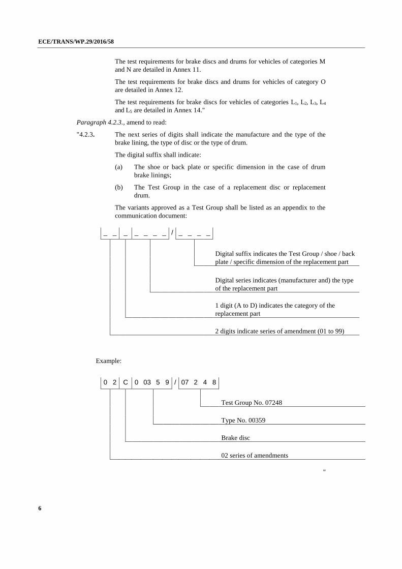
Paragraph 4.2.3., amend to read:
"4.2.3. The next series of digits shall indicate the manufacture and the type of the
brake lining, the type of disc or the type of drum.
The digital suffix shall indicate:
(a) The shoe or back plate or specific dimension in the case of drum
brake linings;
(b) The Test Group in the case of a replacement disc or replacement
drum.
The variants approved as a Test Group shall be listed as an appendix to the
communication document:
_ _ _ _ _ _ _ / _ _ _ _
Digital suffix indicates the Test Group / shoe / back
plate / specific dimension of the replacement part
Digital series indicates (manufacturer and) the type
of the replacement part
1 digit (A to D) indicates the category of the
replacement part
2 digits indicate series of amendment (01 to 99)
Example:
0 2 C 0 03 5 9 / 07 2 4 8
Test Group No. 07248
Type No. 00359
Brake disc
02 series of amendments
"
ECE/TRANS/WP.29/2016/58
7
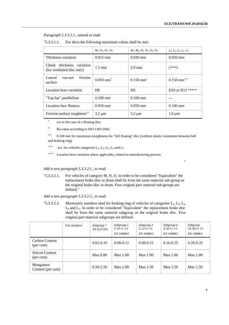
Paragraph 5.3.3.1.1., amend to read:
"5.3.3.1.1. For discs the following maximum values shall be met:
M1, N1, O1, O2 M2, M3, N2, N3, O3, O4 L1, L2, L3, L4 , L5
Thickness variation 0.015 mm 0.030 mm 0.020 mm
Cheek thickness variation
(for ventilated disc only) 1.5 mm 2.0 mm (****)
Lateral run-out friction
surface 0.050 mm* 0.150 mm* 0.150 mm***
Location bore variation H9 H9 D10 or H11 *****
"Top hat" parallelism 0.100 mm 0.100 mm ---
Location face flatness 0.050 mm 0.050 mm 0.100 mm
Friction surface roughness** 3.2 µm 3.2 µm 1.6 µm
* n/a in the case of a floating disc.
** Ra-value according to ISO 1302:2002.
*** 0.100 mm for maximum straightness for "full floating" disc (without elastic constraints between bell
and braking ring)
**** n/a for vehicles categories L1, L2, L3, L4 and L5
***** Location bore variation where applicable, related to manufacturing process.
"
Add a new paragraph 5.3.3.2.1., to read:
"5.3.3.2.1. For vehicles of category M, N, O, in order to be considered "Equivalent" the
replacement brake disc or drum shall be from the same material sub-group as
the original brake disc or drum. Four original part material sub-groups are
defined."
Add a new paragraph 5.3.3.2.2., to read:
"5.3.3.2.2. Martensitic stainless steel for braking ring of vehicles of categories L1, L2, L3,
L4 and L5. In order to be considered "Equivalent" the replacement brake disc
shall be from the same material subgroup as the original brake disc. Five
original part material subgroups are defined.
Test standard Subgroup 1
JIS SUS 410
Subgroup 2
X 10 Cr 13
EN 10088/2
Subgroup 3
X 12 Cr 13
EN 10088/2
Subgroup 4
X 20 Cr 13
EN 10088/2
Subgroup
5X 30 Cr 13
EN 10088/2
Carbon Content
(per cent) 0.02-0.10 0.08-0.12 0.08-0.15 0.16-0.25 0.26-0.35
Silicon Content
(per cent) Max 0.80 Max 1.00 Max 1.00 Max 1.00 Max 1.00
Manganese
Content (per cent) 0.50-2.50 Max 1.00 Max 1.50 Max 1.50 Max 1.50

ECE/TRANS/WP.29/2016/58
8
Test standard Subgroup 1
JIS SUS 410
Subgroup 2
X 10 Cr 13
EN 10088/2
Subgroup 3
X 12 Cr 13
EN 10088/2
Subgroup 4
X 20 Cr 13
EN 10088/2
Subgroup
5X 30 Cr 13
EN 10088/2
Chromium
Content (per cent)
10.00-
14.50 12.00-14.00 11.50-13.50 12.00-14.00 12.00-14.00
Iron Content (per
cent) rest
Hardness HRC ISO 6508-
1:2005
30-40 30-40 30-40 30-40 30-40
"
Add a new paragraph 5.3.3.3.1., to read:
"5.3.3.3.1. Brake disc and brake drum for categories M, N and O
The part has to pass the integrity tests for high load and thermal fatigue
according to Annexes 11 and 12."
Add a new paragraph 5.3.3.3.2., to read:
"5.3.3.3.2. Brake disc for categories L1, L2, L3, L4 and L5
The part has to pass the integrity tests for high load and thermal fatigue
according to Annexes 14."
Paragraph 5.3.4.2., amend to read:
"5.3.4.2. Performance requirements
The part shall pass the following performance tests according to Annexes 11
and 12 for categories M, N and O and Annex 14 for categories L1, L2, L3, L4
and L5:
(a) The performance test according to Regulations Nos. 13 or 13-H or 78;
(b) The Comparison test with dynamic frictional properties of the original
part;
(c) The integrity tests for high load and thermal fatigue. "
Paragraph 5.3.5.1.2., amend to read:
"5.3.5.1.2. Material group
For brake discs for vehicles of categories M, N and O, all material groups
(including their respective subgroups) are considered to be a separate type.
For brake discs for vehicles of categories L1, L2, L3, L4 and L5, all material
groups (excluding the martensitic stainless steel subgroup) are considered to
be a separate type."
Paragraph 5.3.6., amend to read:
"5.3.6. Test group criteria (within the same type)
It is only possible to test interchangeable parts in Test Groups if the
connection between the mounting area and the disc friction faces are of the
same general form….
….
With:
ECE/TRANS/WP.29/2016/58
9
V max, i maximum design speed of the vehicle to which the
replacement part is fitted (in the case of trailers vmax, i is
assumed at least at 80 km/h)
m test mass as defined in Annex 11, paragraph 3.2.1.2., Annex
12, paragraph 3.2.1.2. and Annex 14, paragraph 4.2.1.2.
m replacement part, i mass of the replacement part" of the corresponding vehicle"
Add new paragraphs 5.3.6.1.3. and 5.3.6.1.3.1., to read:
"5.3.6.1.3. Criteria concerning the formation of test groups with regard to replacement
brake discs in vehicles belonging to categories L1, L2, L3, L4 and L5.
5.3.6.1.3.1. Test group relating to the tests stipulated of Annex 14.
This test group includes all brake discs according to the criteria set out in
Annex 15."
Paragraph 5.3.7.4., amend to read:
"5.3.7.4. Tests
Each test group (see paragraph 5.3.6.) within a particular type of replacement
brake disc/drum (see paragraph 5.3.5.) shall be tested by the Technical
Service."
Paragraph 5.3.3.1., amend to read:
"5.3.3.1. Geometric requirements
The brake discs or drums shall be identical to the original brake disc or drum in
respect to all dimensions, geometric features, tolerances and basic design."
Paragraphs 5.3.3.1.1. and 5.3.3.1.2., shall be deleted
Paragraph 5.3.4.1., amend to read:
"5.3.4.1. Geometric requirements
As paragraphs 5.3.4.1.1 and 5.3.4.1.2 plus the same interface dimensions.
An interchangeable replacement …"
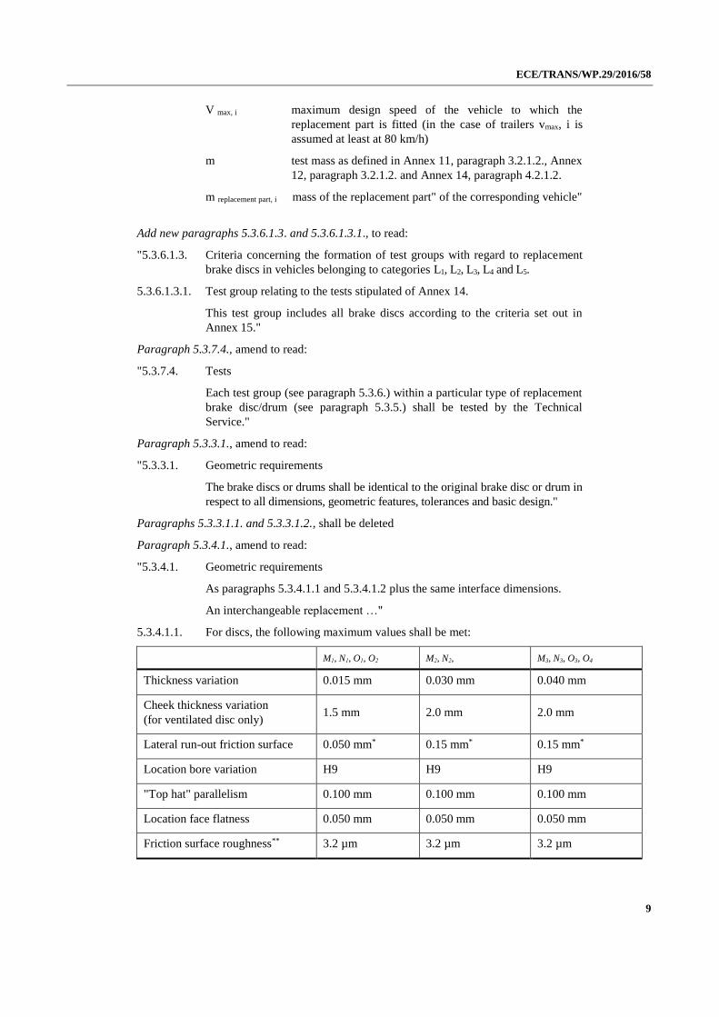
5.3.4.1.1. For discs, the following maximum values shall be met:
M1, N1, O1, O2 M2, N2, M3, N3, O3, O4
Thickness variation 0.015 mm 0.030 mm 0.040 mm
Cheek thickness variation
(for ventilated disc only) 1.5 mm 2.0 mm 2.0 mm
Lateral run-out friction surface 0.050 mm* 0.15 mm* 0.15 mm*
Location bore variation H9 H9 H9
"Top hat" parallelism 0.100 mm 0.100 mm 0.100 mm
Location face flatness 0.050 mm 0.050 mm 0.050 mm
Friction surface roughness** 3.2 µm 3.2 µm 3.2 µm

ECE/TRANS/WP.29/2016/58
10
* N/A in the case of a floating disc
** Ra-value according to ISO 1302:2002
5.3.4.1.2 For drums, the following maximum values shall be met:
M1, N1, O1, O2 M2, M3, N2, N3, O3, O4
Radial run-out friction surface 0.050 mm 0.100 mm
Location bore variation H9 H9
Ovality 0.040 mm 0.150 mm
Location face flatness 0.050 mm 0.050 mm
Friction surface roughness* 3.5 µm 3.5 µm
* Ra-value according to ISO 1302:2002
"
Annex 9,
Title of Part B, amend to read:
"Part B: Conformity of production for brake discs and drums in cast
iron"
Add Part C, to read:
"Part C: Conformity of production for brake discs in martensitic
stainless steel
1. Introduction
Part C applies to replacement brake discs approved to this Regulation.
2. Requirements
Conformity of production is to be demonstrated through the routine control
and documentation of at least the following:
2.1. Chemical composition
2.2. Mechanical properties
Rockwell C hardness measured in accordance with ISO 6508-1:2005.
In each case the measurements must be made on samples taken from the
actual brake disc or drum.
2.3. Geometric features
Brake Discs:
(a) Thickness variation;
(b) Friction surface run out;
(c) Friction surface roughness.

ECE/TRANS/WP.29/2016/58
11
2.4. Acceptance criteria
With each application for approval of a replacement brake disc or drum there
shall be submitted a production specification covering:
(a) Chemical composition and its permitted range, or where
appropriate, maximum value, for each element;
(b) Mechanical properties as per paragraph 2.3. and their permitted range,
or where appropriate, minimum value.
During routine production of an approved replacement brake disc or drum
production must demonstrate compliance with these registered specifications.
In the case of geometric features the values prescribed in paragraph 5.3.3.1.1.
for brake discs must not be exceeded.
2.5. Documentation
The documentation shall contain the manufacturer’s maximum and minimum
permitted values.
2.6. Test frequency
The measurements prescribed in this annex should be carried out for each
production batch."
Annex 10,
Paragraph 1., amend to read:
"1. Brake disc design types for M, N and O categories (examples)
…"
Paragraph 2., amend to read:
"2. Brake drum for M, N and O categories (examples)
…"
Add a new paragraph 3., to read:
"3. Brake disc design types for L1, L2, L3, L4 and L5 categories (examples)
One-piece type: brake disc with braking surface and bell made in a single
piece and, therefore, of the same material
Composed fixed type: brake disc having the braking ring made of steel, while the
bell is of other material, generally aluminium; the 2 components are rigidly
bounded by a screwed or riveted connection.
ECE/TRANS/WP.29/2016/58
12
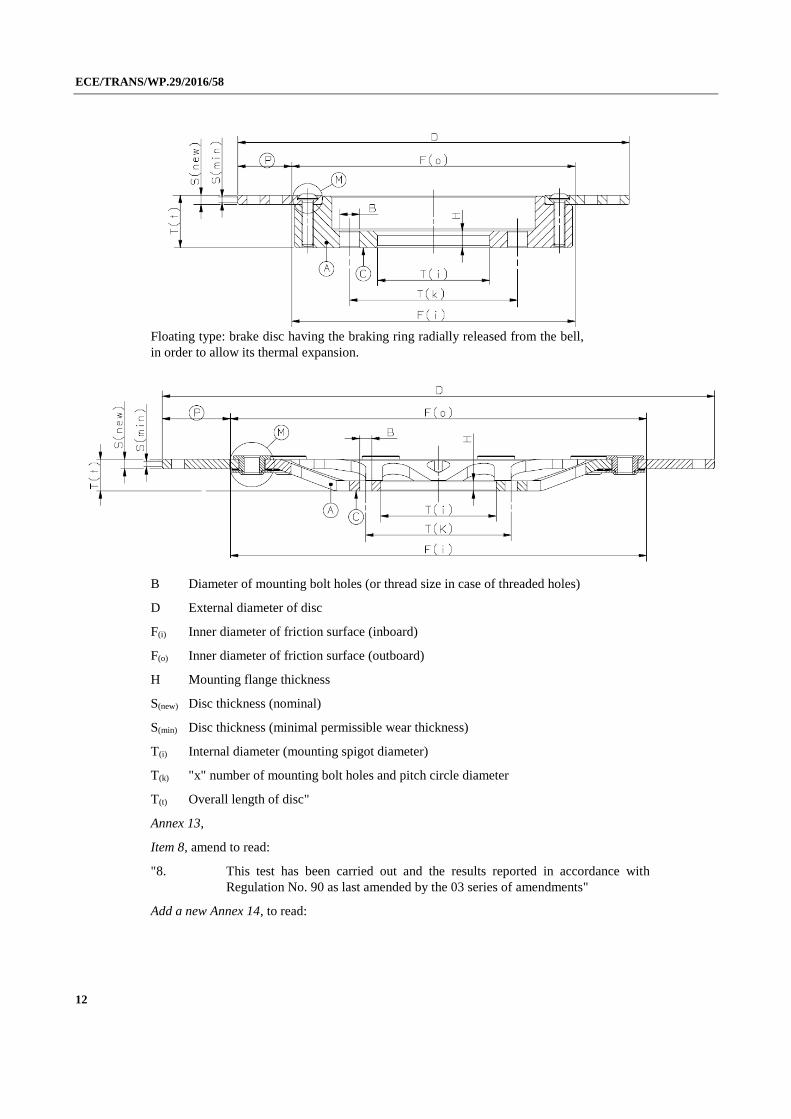
Floating type: brake disc having the braking ring radially released from the bell,
in order to allow its thermal expansion.
B Diameter of mounting bolt holes (or thread size in case of threaded holes)
D External diameter of disc
F(i) Inner diameter of friction surface (inboard)
F(o) Inner diameter of friction surface (outboard)
H Mounting flange thickness
S(new) Disc thickness (nominal)
S(min) Disc thickness (minimal permissible wear thickness)
T(i) Internal diameter (mounting spigot diameter)
T(k) "x" number of mounting bolt holes and pitch circle diameter
T(t) Overall length of disc"
Annex 13,
Item 8, amend to read:
"8. This test has been carried out and the results reported in accordance with
Regulation No. 90 as last amended by the 03 series of amendments"
Add a new Annex 14, to read:

ECE/TRANS/WP.29/2016/58
13
"Annex 14
Requirements for replacement brake discs for vehicles of categories L1, L2, L3, L4 and L5
1. Test overview
The tests required in paragraph 5.3. of this Regulation are detailed
as follows according to the vehicle category.
Table A14/1.
Static bench test Vehicle test Alternative dynamometer test
Resistance to static torque
test
2. --- ---
Performance tests
according to Regulation
No. 78
---
3.2.3. Dry stop test 4.4.1. Dry stop test
3.2.4. Wet brake test ---
3.2.5. Heat fade test 4.4.2. Heat fade test
Comparison test with
original part
--- 3.2.6. Testing the
dynamic frictional
properties
4.4.3. Testing the
dynamic frictional
properties
Integrity test --- No vehicle test − use
dynamometer test
5.1. Brake disc thermal
fatigue test
For each disc type, at least one test group (see definition in paragraph 5.3.6. of
this Regulation) requires the "Dry stop", "Wet brake" and "Heat fade" tests to
be carried out on a vehicle.
2. Static bench test requirements
2.1. Purpose
To verify the resistance of the bell and, in case of floating discs, of the
connection system to the braking ring when the disc is subjected to a braking
torque.
2.2. Test procedure and conditions
Static test performed on special test bench shown in Figure 1.
ECE/TRANS/WP.29/2016/58
14
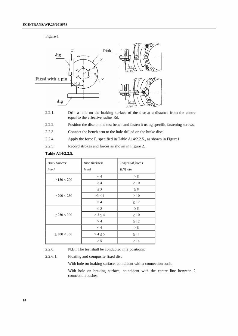
Figure 1
2.2.1. Drill a hole on the braking surface of the disc at a distance from the centre
equal to the effective radius Rd.
2.2.2. Position the disc on the test bench and fasten it using specific fastening screws.
2.2.3. Connect the bench arm to the hole drilled on the brake disc.
2.2.4. Apply the force F, specified in Table A14/2.2.5., as shown in Figure1.
2.2.5. Record strokes and forces as shown in Figure 2.
Table A14/2.2.5.
Disc Diameter
[mm]
Disc Thickness
[mm]
Tangential force F
[kN] min
≥ 150 < 200 ≤ 4 ≥ 8
> 4 ≥ 10
≥ 200 < 250
≤ 3 ≥ 8
>3 ≤ 4 ≥ 10
> 4 ≥ 12
≥ 250 < 300
≤ 3 ≥ 8
> 3 ≤ 4 ≥ 10
> 4 ≥ 12
≥ 300 < 350
≤ 4 ≥ 8
> 4 ≤ 5 ≥ 11
> 5 ≥ 14
2.2.6. N.B.: The test shall be conducted in 2 positions:
2.2.6.1. Floating and composite fixed disc
With hole on braking surface, coincident with a connection bush.
With hole on braking surface, coincident with the centre line between 2
connection bushes.
Disk Jig
Jig
Fixed with a pin
ECE/TRANS/WP.29/2016/58
15
2.2.6.2. One piece disc
With hole on braking surface, coincident with a fixing hole.
With hole on braking surface, coincident with the centre line between 2 fixing
holes.
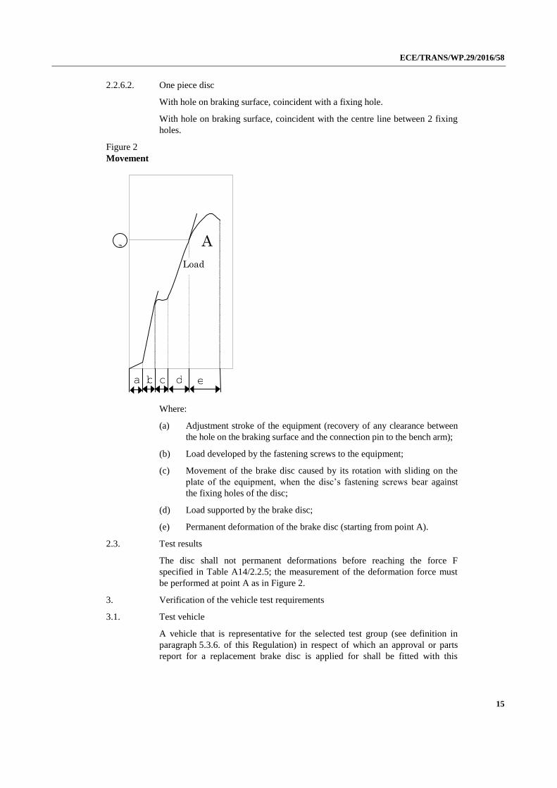
Figure 2
Movement
Where:
(a) Adjustment stroke of the equipment (recovery of any clearance between
the hole on the braking surface and the connection pin to the bench arm);
(b) Load developed by the fastening screws to the equipment;
(c) Movement of the brake disc caused by its rotation with sliding on the
plate of the equipment, when the disc’s fastening screws bear against
the fixing holes of the disc;
(d) Load supported by the brake disc;
(e) Permanent deformation of the brake disc (starting from point A).
2.3. Test results
The disc shall not permanent deformations before reaching the force F
specified in Table A14/2.2.5; the measurement of the deformation force must
be performed at point A as in Figure 2.
3. Verification of the vehicle test requirements
3.1. Test vehicle
A vehicle that is representative for the selected test group (see definition in
paragraph 5.3.6. of this Regulation) in respect of which an approval or parts
report for a replacement brake disc is applied for shall be fitted with this
A
a b c d e
Load
A

ECE/TRANS/WP.29/2016/58
16
replacement brake disc as well as be equipped with test devices for testing the
brakes pursuant to the provisions of Regulation No. 78.
The replacement brake disc shall be fitted to the wheel in question together
with an accompanying brake lining which has been type approved according to
Regulations Nos. 78 or 90, available from the vehicle.
Unless a uniform procedure is laid down for how braking is to effected, the test
shall be carried out following agreement with the Technical Service. All the
tests listed below shall be carried out on brakes that have been bedded in.
The same "bedding-in" programme shall be used for both replacement and
original brake discs.
3.2. Service braking system
3.2.1. Brake temperature measurement
This procedure shall be carried out pursuant to Regulation No.78, Annex 3,
paragraph 2.4.
3.2.2. Burnishing procedure
This procedure shall be carried out pursuant to Regulation No.78, Annex 3,
paragraph 2.5.
3.2.3. Dry stop test
This test shall be carried out pursuant to Regulation No. 78, Annex 3,
paragraph 3.
3.2.4. Wet brake test
This test shall be carried out pursuant to Regulation No. 78, Annex 3,
paragraph 6.
3.2.5. Heat fade test
The test is applicable to vehicle categories L3, L4 and L5.
This test shall be carried out pursuant to Regulation No. 78, Annex 3,
paragraph 7.
3.2.6. Testing the dynamic frictional properties (comparison test conducted on the
individual wheel)
For this test, the vehicle shall be laden and all brake applications carried out on
a flat road with the engine disconnected.
The service braking system of the vehicle shall be provided with a device that
separates the front-wheel brake from the rear-wheel brake so that they can
always be operated independently of one another.
If an approval or a part report is required in connection with a replacement
brake disc for the front-wheel brake, the rear-wheel brakes shall remain
inoperative throughout the test.
If an approval or a part report is required in connection with a replacement
brake disc for the rear-wheel brake, the front-wheel brake shall remain
inoperative throughout the test.
3.2.6.1. Performance comparison test when the brakes are cold

ECE/TRANS/WP.29/2016/58
17
With cold brakes, the performance of the replacement brake disc shall be
compared with the original equivalent by comparing the results of the test below.
3.2.6.2. Using the replacement brake disc, at least six consecutive brake applications
with different, gradually increasing control forces or brake pressures are
carried out as part of the process up to the point at which the wheel lock, or up
to a mean fully developed deceleration of 6 m/s² or up to the maximum control
force or line pressure permitted for this category of vehicle, in which
connection the initial speed for the testing of front or rear wheel brake disc is
as per the table below:
Table A14/3.2.6.2.
Vehicle category
Test speed in km/h
Front wheel Rear wheel
L1, L2, 30 30
L3, L4, L5, 70 45
Prior to each brake application, the initial temperature of the brake disc
shall be ≤ 80 °C.
3.2.6.3. The brake test described in paragraph 3.2.6.2. also has to be carried out using
the original brake disc.
3.2.6.4. The dynamic frictional properties of the replacement brake disc can be
regarded as similar to those of the original brake disc, provided the values
attained in relation to the mean fully developed deceleration at the same
operating pressures or control forces in the region of the upper 2/3 of the curve
generated do not deviate by either ±15 per cent or ±0.4 m/s² from those of the
original brake disc (see an example of the curve in Figures 3 and 4).
Figure 3

ECE/TRANS/WP.29/2016/58
18
Figure 4
4. Inertia dynamometer test
4.1. Equipping the dynamometer
For testing purposes, the dynamometer shall be fitted out with the original
brake caliper. The inertia dynamometer shall be equipped with a constant
torque device and equipment for recording rotational speed, brake pressure, the
number of revolutions after braking has commenced, brake torque, the braking
period and the temperature of the brake discs on a continuous basis.
4.2. Test conditions
4.2.1. Inertia mass of the inertia dynamometer
The inertia mass of the inertia dynamometer shall be set as close as possible,
with a permissible variation of ± 5 per cent, to the theoretically required value
which corresponds to that part of the total inertia of the vehicle braked by the
appropriate wheel. The formula used for calculation purposes is as follows:
I = m rdyn²
Where:
I = rotary inertia (kgm2);
rdyn = dynamic rolling radius of the tyre (m);
m = test mass (part of the maximum mass of the vehicle braked by
the appropriate wheel) as stipulated by this Regulation.
4.2.1.1. Dynamic rolling radius
In calculating the inertia mass, the dynamic rolling radius (rdyn) of the largest
tyre authorised for the vehicle shall be taken into account.
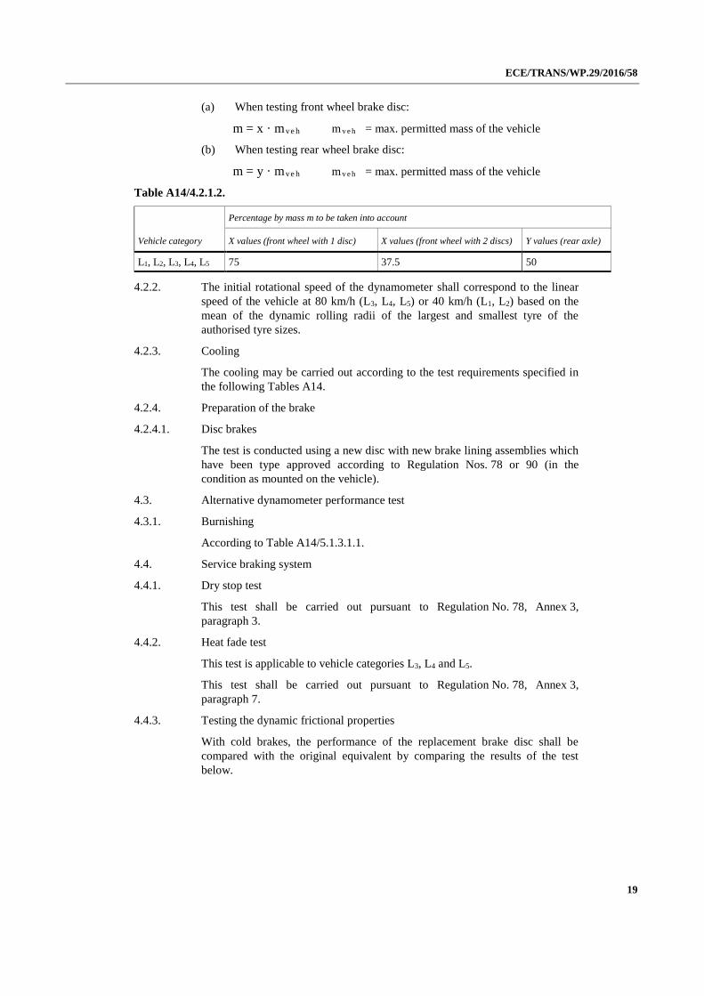
4.2.1.2. Test mass
The test mass for calculating the inertia mass shall be as follows:
ECE/TRANS/WP.29/2016/58
19
(a) When testing front wheel brake disc:
m = x · mve h m v e h = max. permitted mass of the vehicle
(b) When testing rear wheel brake disc:
m = y · mve h m v e h = max. permitted mass of the vehicle
Table A14/4.2.1.2.
Vehicle category
Percentage by mass m to be taken into account
X values (front wheel with 1 disc) X values (front wheel with 2 discs) Y values (rear axle)
L1, L2, L3, L4, L5 75 37.5 50
4.2.2. The initial rotational speed of the dynamometer shall correspond to the linear
speed of the vehicle at 80 km/h (L3, L4, L5) or 40 km/h (L1, L2) based on the
mean of the dynamic rolling radii of the largest and smallest tyre of the
authorised tyre sizes.
4.2.3. Cooling
The cooling may be carried out according to the test requirements specified in
the following Tables A14.
4.2.4. Preparation of the brake
4.2.4.1. Disc brakes
The test is conducted using a new disc with new brake lining assemblies which
have been type approved according to Regulation Nos. 78 or 90 (in the
condition as mounted on the vehicle).
4.3. Alternative dynamometer performance test
4.3.1. Burnishing
According to Table A14/5.1.3.1.1.
4.4. Service braking system
4.4.1. Dry stop test
This test shall be carried out pursuant to Regulation No. 78, Annex 3,
paragraph 3.
4.4.2. Heat fade test
This test is applicable to vehicle categories L3, L4 and L5.
This test shall be carried out pursuant to Regulation No. 78, Annex 3,
paragraph 7.
4.4.3. Testing the dynamic frictional properties
With cold brakes, the performance of the replacement brake disc shall be
compared with the original equivalent by comparing the results of the test
below.
ECE/TRANS/WP.29/2016/58
20
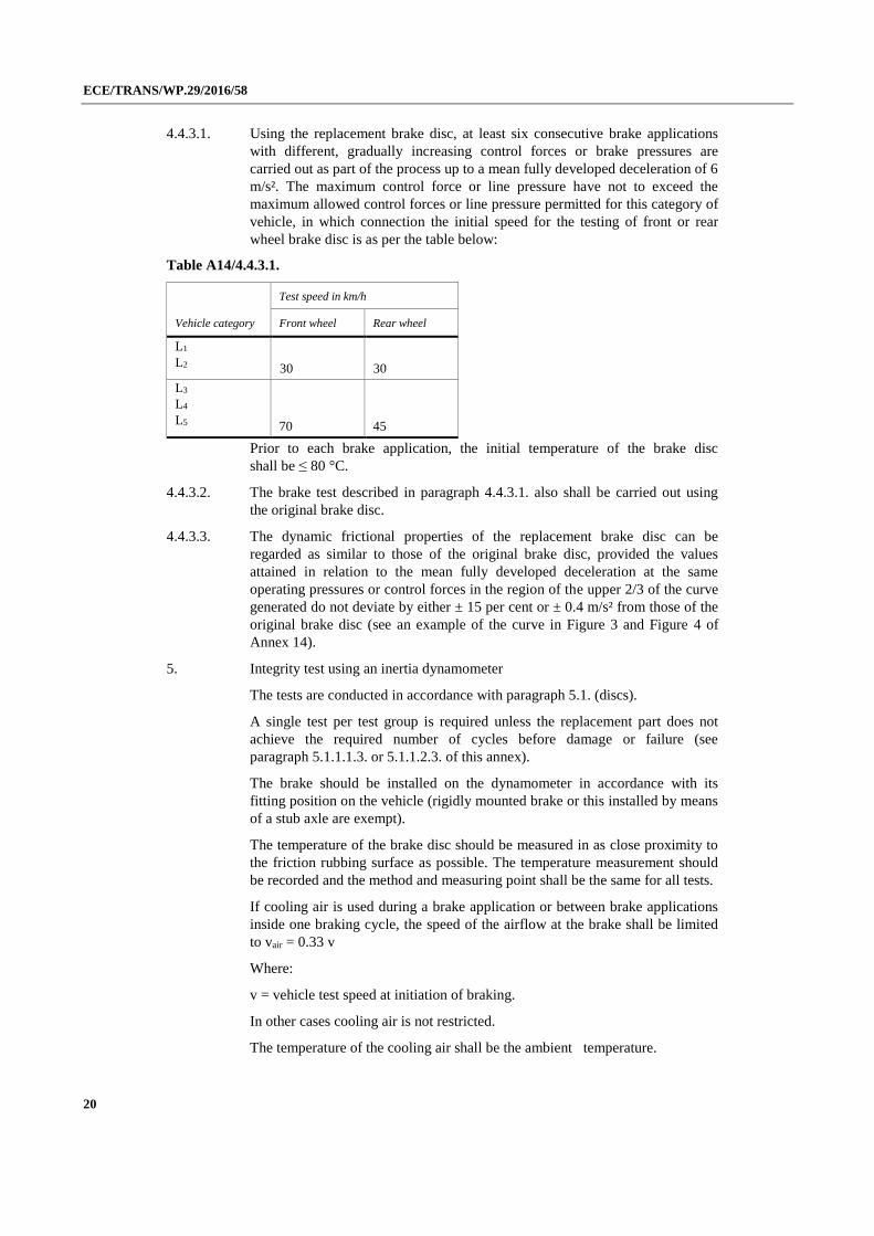
4.4.3.1. Using the replacement brake disc, at least six consecutive brake applications
with different, gradually increasing control forces or brake pressures are
carried out as part of the process up to a mean fully developed deceleration of 6
m/s². The maximum control force or line pressure have not to exceed the
maximum allowed control forces or line pressure permitted for this category of
vehicle, in which connection the initial speed for the testing of front or rear
wheel brake disc is as per the table below:
Table A14/4.4.3.1.
Vehicle category
Test speed in km/h
Front wheel Rear wheel
L1
L2 30 30
L3
L4
L5 70 45
Prior to each brake application, the initial temperature of the brake disc
shall be ≤ 80 °C.
4.4.3.2. The brake test described in paragraph 4.4.3.1. also shall be carried out using
the original brake disc.
4.4.3.3. The dynamic frictional properties of the replacement brake disc can be
regarded as similar to those of the original brake disc, provided the values
attained in relation to the mean fully developed deceleration at the same
operating pressures or control forces in the region of the upper 2/3 of the curve
generated do not deviate by either ± 15 per cent or ± 0.4 m/s² from those of the
original brake disc (see an example of the curve in Figure 3 and Figure 4 of
Annex 14).
5. Integrity test using an inertia dynamometer
The tests are conducted in accordance with paragraph 5.1. (discs).
A single test per test group is required unless the replacement part does not
achieve the required number of cycles before damage or failure (see
paragraph 5.1.1.1.3. or 5.1.1.2.3. of this annex).
The brake should be installed on the dynamometer in accordance with its
fitting position on the vehicle (rigidly mounted brake or this installed by means
of a stub axle are exempt).
The temperature of the brake disc should be measured in as close proximity to
the friction rubbing surface as possible. The temperature measurement should
be recorded and the method and measuring point shall be the same for all tests.
If cooling air is used during a brake application or between brake applications
inside one braking cycle, the speed of the airflow at the brake shall be limited
to vair = 0.33 v
Where:
v = vehicle test speed at initiation of braking.
In other cases cooling air is not restricted.
The temperature of the cooling air shall be the ambient temperature.

ECE/TRANS/WP.29/2016/58
21
5.1. Brake disc thermal fatigue test
This test is conducted using a new disc, an original brake caliper of the
vehicle(s) concerned and new brake lining assemblies of the vehicle(s)
concerned which have been type approved according to Regulations Nos. 78 or
90 (in the condition as mounted on the vehicle).
Worn brake linings may be replaced during the test if necessary.
5.1.1. This test is applicable to vehicle categories L3, L4 and L5.
5.1.2. Test conditions
The inertia mass of the inertia dynamometer shall be determined in accordance
with the requirements laid down in paragraphs 4.2.1., 4.2.1.1. and 4.2.1.2. of
Annex 14.
The rotational speed of the dynamometer shall correspond to the linear test
speed of the vehicle based on the mean of the largest and smallest dynamic
rolling radius of the tyres authorized for that vehicle.
5.1.3. Front disc
5.1.3.1. Test programme
5.1.3.1.1. Burnishing
According to Table A14/5.1.3.1.1.
Table A14/5.1.3.1.1.
Burnishing
Step Vehicle gross
weight
[kg]
Initial
speed
[km/h]
Final speed
[km/h]
Deceleration
[m/s2]
Starting
temperature
before the
braking
[°C] MAX
Brakings
quantity
[---]
Max speed of the permitted
airflow during the brake
application
[m/s]
1 75% / disc q.ty 80 30 4 100 60 30
5.1.3.1.2. Fatigue test
According to Table A14/5.1.3.1.2.
Table A14/5.1.3.1.2.
Thermal fatigue test
Step Vehicle gross
weight
[kg]
Initial speed
[km/h]
Final speed
[km/h]
Deceleration
[m/s2]
Starting
temperature
before the
brakings
[°C] +/- 10 °C
Time between 2
consecutive
brakings
[s]
Brakings
quantity
[---]
Max speed of
the permitted
airflow during
the brake
application
[m/s]
1
thermal
75% / discs
q.ty 50% Vmax 5 7 100 (a) 30 5 20
2
functional
75% / discs
q.ty 80% Vmax 5 8 200 --- 1 30
ECE/TRANS/WP.29/2016/58
22
Thermal fatigue test
Step Vehicle gross
weight
[kg]
Initial speed
[km/h]
Final speed
[km/h]
Deceleration
[m/s2]
Starting
temperature
before the
brakings
[°C] +/- 10 °C
Time between 2
consecutive
brakings
[s]
Brakings
quantity
[---]
Max speed of
the permitted
airflow during
the brake
application
[m/s]
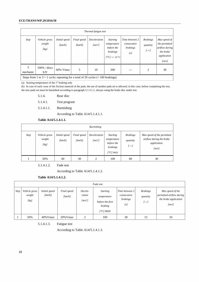
3
mechanic
100% / discs
q.ty 60% Vmax 5 10 200 --- 2 30
Steps from 1 to 3 = 1 cycle; repeating for a total of 20 cycles (= 160 brakings)
(a) Starting temperature of the 1st braking only
(b) In case of early wear of the friction material of the pads, the use of another pads set is allowed; in this case, before completing the test,
the new pads set must be burnished according to paragraph 5.1.3.1.1, always using the brake disc under test.
5.1.4. Rear disc
5.1.4.1. Test program
5.1.4.1.1. Burnishing
According to Table A14/5.1.4.1.1.
Table A14/5.1.4.1.1.
Burnishing
Step Vehicle gross
weight
[kg]
Initial speed
[km/h]
Final speed
[km/h]
Deceleration
[m/s2]
Starting
temperature
before the
brakings
[°C] MAX
Brakings
quantity
[---]
Max speed of the permitted
airflow during the brake
application
[m/s]
1 50% 60 30 2 100 60 30
5.1.4.1.2. Fade test
According to Table A14/5.1.4.1.2.
Table A14/5.1.4.1.2.
Fade test
Step Vehicle gross
weight
[kg]
Initial speed
[km/h]
Final speed
[km/h]
Decele-
ration
[m/s2]
Starting
temperature
before the first
braking
[°C] MAX
Time between 2
consecutive
brakings
[s]
Brakings
quantity
[---]
Max speed of the
permitted airflow during
the brake application
[m/s]
1 50% 40%Vmax 20%Vmax 2 100 30 15 10
5.1.4.1.3. Fatigue test
According to Table A14/5.1.4.1.3.

ECE/TRANS/WP.29/2016/58
23
Table A14/5.1.4.1.3.
Thermal fatigue test
Step Vehicle
gross
weight
[kg]
Initial speed
[km/h]
Final speed
[km/h]
Deceleration
[m/s2]
Starting
temperature
before the
braking
[°C] +/- 10°C
Time between 2
consecutive
brakings
[s]
Brakings
quantity
[---]
Max speed of the
permitted airflow
during the brake
application
[m/s]
1
thermal 50% 40% Vmax 20% Vmax 3 100 (a) 30 5 20
2
functional 50%
50% Vmax (b)
5 4 200 --- 1 30 60% Vmax (c)
75% Vmax (d)
3
mechanic 90%
40% Vmax (b)
5 5 200 --- 2 30 48% Vmax (c)
60% Vmax (d)
Steps from 1 to 3 = 1 cycle; repeating for a total of 20 cycles (= 160 brakings)
(a) Starting temperature of the 1st braking only
(b) Disc diameter ≤ 245 mm
(c) Disc diameter > 245 < 280 mm (d) Disc diameter ≥ 280 mm
(e) In case of early wear of the friction material of the pads, the use of another pads set is allowed; in this case, before
completing the test, the new pads set must be burnished according to paragraphs 5.1.4.1.1. – 5.1.4.1.2., always using the brake disc under test.
5.1.5. Test result (brake disc thermal fatigue test)
The test is regarded as having been passed if the cycles prescribed in:
(a) Tables A14/5.1.3.1.1. – 5.1.3.1.2. for front discs
(b) Tables A14/5.1.4.1.1. – 5.1.4.1.2. - 5.1.4.1.3. for rear discs
are completed without damage or failure.
If less than 20 cycles, according to "Thermomechanical Fatigue test" in Tables
A14/5.1.3.1.2. and A14/5.1.4.1.3., but more than 15 are completed without
damage or failure, then the test must be repeated on a new replacement part.
Under these circumstances both tests must complete more than 15 cycles
without damage or failure for the part to have passed the test.
If less than 15 cycles are completed before damage or failure, then a test should
be conducted on the original part and the results compared.
If the damage of failure point is no worse than the quantity of cycles of the
original part – 10 per cent, then the test is regarded as having been passed.
Damage or failure, in this context, means:
5.1.5.1. During the test:
Temperature exceeds 600 °C.
5.1.5.2. After the test:
(a) Contact between caliper and disc;
ECE/TRANS/WP.29/2016/58
24
(b) Cracks, permanent deformation or breakings;
(c) Abnormal wear;
(d) A 0.150 mm maximum increasing of run-out, compared to the initial
value measured before the test, is allowed;
(e) A 0.250 mm maximum run-out is allowed;
(f) A 0.100 mm maximum (for "full floating" disc) straightness increasing,
compared to the initial value measured before the test, is allowed."
Add a new Annex 15, to read:
"Annex 15
Criteria for groups of discs for vehicles of categories L1, L2, L3, L4 and L5
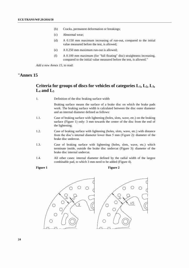
1. Definition of the disc braking surface width
Braking surface means the surface of a brake disc on which the brake pads
work. The braking surface width is calculated between the disc outer diameter
and an internal diameter defined as follows:
1.1. Case of braking surface with lightening (holes, slots, wave, etc.) on the braking
surface (Figure 1) only: 3 mm towards the centre of the disc from the end of
the lightening.
1.2. Case of braking surface with lightening (holes, slots, wave, etc.) with distance
from the disc’s internal diameter lower than 5 mm (Figure 2): diameter of the
brake disc undercut.
1.3. Case of braking surface with lightening (holes, slots, wave, etc.) which
terminate inside, outside the brake disc undercut (Figure 3): diameter of the
brake disc internal undercut.
1.4. All other cases: internal diameter defined by the radial width of the largest
combinable pad, to which 3 mm need to be added (Figure 4).
Figure 1 Figure 2

ECE/TRANS/WP.29/2016/58
25
Figure 3 Figure 4
2. Groups of discs
"Group of discs" means a grouping of similar discs, so that the tests performed
on a single disc are considered valid for the entire group of similar discs.
Discs belonging to the same group must have following features, as indicated
at following paragraphs from 2.1. to 2.9.
For a given group of discs, the approval tests may be performed on one disc,
belonging to the group, subjected to the highest braking torque and to the
largest energy to be absorbed.
The similarity between the discs is defined by following grouping criteria, that
must be simultaneously fulfilled:
2.1. Same type of the reference disc for that group (one piece, composed fixed or
floating).
2.2. Braking surface material to be chosen among those listed at paragraph
5.3.3.2.2.; other materials can be used provided that, under approval, they are
declared with equal demonstration of test results according to paragraph 8. In
this case, the extension applies to all groups listed in Table 3 for dimensions
equal or lower to that demonstrated.
2.3. Braking surface lightening: any solution is allowed (holes, slots, wave, etc.)
provided that:
2.3.1. For discs having the same diameter and thickness: the mass change of the
braking surface swept by the pads must be within the range of ± 20 per cent
with respect to the reference disc.
2.3.2. All other cases: the ratio between the area of the disc braking surface, as
defined in paragraph 4., and the lightening area (sum of the area of holes, slots,
etc.) must match those of the reference disc, with tolerance of – 20 per cent
maximum.
Examples:
R reference disc, Ø 300 mm:
Outer diameter 300 mm, radial width of the braking surface 36.5 mm ≥ total
area A = 302 cm2
Lightening on the braking surface: 64 holes diameter 7 mm ≥ total area

ECE/TRANS/WP.29/2016/58
26
B = 24.6 cm2
A/B ratio = 12.3
S disc Ø 285:
Outer diameter 285 mm, radial width of the braking surface 41 mm ≥ total area
A = 314 cm2
Lightening on the braking surface: 60 holes diameter 7 mm ≥ total area
B = 23 cm2
A/B ratio = 13.7
S disc may belong to the same group of R reference disc, as the 13,7 ratio is
greater than the 12, ratio of R disc.
T disc Ø 260:
Outer diameter 260 mm, radial width of the braking surface 29 mm ≥ total area
A = 210 cm2
Lightening on the braking surface: 64 holes diameter 7 mm ≥ total area
B = 24.6 cm2
A/B ratio = 8.5
T disc may not belong to the same group of R reference disc as the 8.5 ratio,
– 31 per cent with respect to the 12.3 ratio of R disc, therefore over the
specified tolerance of – 20 per cent maximum.
2.4. Same material and mechanical properties, as specified in the international
standard for materials, or higher, for the bell.
In the case of disc with steel bell, compared with the disc tested for approval
with aluminium bell, the exception of belonging to the same group is allowed;
the reverse is not allowed.
2.5. Same material and mechanical properties, as specified in the international
standard for materials, or higher, for the bell/braking surface fasteners.
2.6. Spokes of the bell with full/empty ratio – measured on the average
circumference between end of the mounting face and beginning of the braking
surface – within the range ± 20 per cent, thickness within the range (+ 30 per
cent) ÷ (– 10 per cent) and same mechanical properties, as specified in the
international standard for materials, with respect to the reference disc.
2.7. Same technical solution for the bell-braking surface fasteners (same drawing
and materials; for the quantity of bell-braking surface fasteners, permitted the
same quantity with a tolerance of +2 –0).
2.8. The quantity of fixing holes is not binding by group belonging, in order to
ensure interchangeability with original disc.
2.9. Outer diameter included in the range of 50 mm, according to Table 2.9.:

ECE/TRANS/WP.29/2016/58
27
Table A15/2.9.
Range
[mm]
One piece Composite
fixed
Floating discs
≥ 150 < 200 X X X
≥ 200 < 250 X X X
≥ 250 < 300 X X X
≥ 300 < 350 X X X
There are no groups for "peripheral" discs (fitted on the wheel outer diameter).
Note:
For new applications that will be included into an existing group, an increase of
10 per cent maximum kinetic energy is allowed with reference to the value
used for the approval of the disc of the reference group.
Data for the new calculation of kinetic energy must be traced from the product
data sheet issued by the vehicle manufacturer.
In the case of discs with applications on both wheels, front and rear, the
approval tests at paragraph 8. shall be conducted on heaviest application."