army tm 9-6115-664-13&p how to use this …army tm 9-6115-664-13&p operator, unit, and...
TRANSCRIPT

ARMY TM 9-6115-664-13&P
OPERATOR, UNIT, AND DIRECTSUPPORT MAINTENANCE MANUALWITH REPAIR PARTS AND SPECIAL
TOOLS LIST
5KW, 28VDC, AUXILIARY POWER UNIT(APU) MEP 952B
NSN 6115-01-452-6513 (EIC: N/A)
DISTRIBUTION STATEMENT A: Approvedfor public release; distribution is unlimited.
HOW TO USE THIS MANUALPage vi
EQUIPMENT DESCRIPTIONPage 1-3
PRINCIPLES OF OPERATIONPage 1-16
CONTROLS AND INDICATORSPage 2-2
OPERATOR PMCSPage 2-7
OPERATOR MAINTENANCEPage 3-10
UNIT PMCSPage 4-6
UNIT TROUBLESHOOTINGPage 4-11
UNIT MAINTENANCEPage 4-37
DIRECT SUPPORT TROUBLESHOOTINGPage 5-3
DIRECT SUPPORT MAINTENANCEPage 5-8
MAINTENANCE ALLOCATION CHARTPage B-1
REPAIR PARTS AND SPECIALTOOLS LIST Page G-1
HEADQUARTERS, DEPARTMENT OF THE ARMY1 NOVEMBER 2000

TM 9-6115-664-13&P
WARNING SUMMARY
The following safety precautions are for personnel to understand and apply during many phases of operation andmaintenance. Disregard of these warnings and precautionary information can result in serious injury or death.
Warning statements have been strategically placed throughout this manual prior to the operating or maintenanceprocedures considered essential to the protection of personnel. Prior to starting any task the warning included in the textfor that task must be reviewed and followed.
This manual describes physical and chemical processes which may require the use of chemicals, solvents, paints, orother commercially available material. The user of this manual should obtain the material safety data sheets(Occupational Safety and Heath Act (OSHA) Form 20 or equivalent) from the manufacturer or suppliers of materials to beused. The user must be completely familiar with the manufacturer/supplier information and adhere to the procedures,recommendations, warnings, and cautions of the manufacturer/supplier for the safe use, handling, storage, and disposalof these materials.
WARNING
Operating personnel must observe every safety regulation at all times. Do notreplace components or make adjustments inside the equipment with the voltagesupply turned on. Dangerous potentials may exist under certain conditions whenthe power control is in the off position. Avoid casualties by always removingpower and discharging and grounding a circuit before touching it.
WARNING
High current is produced when the unit is in operation. Use care when workingaround an open control panel with the APU operating. Improper operation and/orfailure to follow this warning could result in personal injury or death byelectrocution.
WARNING
Never attempt to start the APU if it is not properly grounded. Failure to observethis warning could result in serious injury or death by electrocution.
WARNING
DC voltages are present at APU electrical components even with the APU shutdown. Avoid shorting any positive terminal with ground / negative. Failure toobserve this warning can result in personal injury and equipment damage.
a

TM 9-6115-664-13&P
WARNING
Never attempt to connect or disconnect load cables while the unit is running.Failure to observe this warning could result in severe personal injury or death byelectrocution and equipment damage.
WARNING
Never reach into the enclosure to service or adjust the equipment alone. Makesure to work with someone who can render aid in case of an emergency.
WARNING
Exhaust discharge from APU contains deadly gases. Do not operate APU inenclosed area unless exhaust discharge is properly vented outside. Position asfar away from personnel, shelters, and occupied vehicles as possible. Failure toobserve this warning can result in severe personal injury or death due to carbonmonoxide poisoning.
FOR ARTIFICIAL RESPIRATION, REFER TO FM 21-11.
THE BEST DEFENSE AGAINST CARBON MONOXIDE POISONING IS GOOD VENTILATION.
WARNING
The fuels used in this general set are flammable. Do not smoke or use open flameduring operation and maintenance. Failure to observe this warning can result insevere personal injury or death and equipment damage due to potential flame andexplosion.
WARNING
Fuel from spray orifice may be under high pressure and can penetrate Clothingand skin. Always direct fuel injection nozzle tip away from personnel. Wearprotective goggles and properly relieve fuel pressure before working on the fuelsystem. Failure to observe this warning can result in personal injury.
b

TM 9-6115-664-13&P
WARNING
If diesel fuel is injected into skin, seek medical attention immediately. Failure toobserve this warning can result in severe personal injury.
WARNING
Cleaning solvents are flammable and toxic to eyes, skin, and respiratory tract.Skin and eye protections are required when working in contact with cleaningsolvents. Avoid repeated or prolonged contact. Work in well-ventilated area only.Keep away from heat, sparks, and open flame, and do not smoke while usingcleaning solvents. Failure to observe this warning can cause injury to personnel.
WARNING
Cleaning with compressed air can cause flying particles. Wear protective glassesand use clean, low pressure air of less than 30 psi (206.8 kPa). Failure to observethis warning can result in eye injury.
WARNING
The adhesives used in maintenance of the APU (see Appendix E) are flammableand toxic. Vapors may ignite explosively. Avoid breathing in vapors. Provideadequate ventilation to prevent vapor concentrations in excess of permissibleexposure levels. Keep away from heat, sparks, and open flame. Do not smoke.Extinguish all flames and turn off non-explosion-proof electrical equipment duringuse until vapors are dissipated. Close containers tightly after use. Failure toobserve this warning can result in personal injury.
WARNING
Avoid contacting metal items with bare skin in extreme cold weather. Failure toobserve this warning can result in personal injury.
c

TM 9-6115-664-13&P
WARNING
Metal jewelry can conduct electricity. Remove metal jewelry when working onelectrical system or components. Failure to observe this warning can result insevere personal injury from electric shock.
WARNING
Jewelry and other loose and dangling articles and clothing can be caught inmoving parts. Remove jewelry and loose and dangling articles and clothing beforeworking on the APU. Failure to observe this warning can result in personal injury.
WARNING
Adhere to the manual regarding lifting restriction. Do not lift heavy objects overpersonnel. Do not stand in the operating area of a lifting device. Failure toobserve this warning can result in severe personal injury and/or equipmentdamage.
WARNING
Disconnect electrical cable from NATO receptacle before performing maintenanceon the electrical system. Failure to do so can result in electrical shock.
WARNING
CARC paint dust is a health hazard. Wear protective eyewear, mask, and gloveswhen sanding CARC painted surfaces. Failure to comply can cause personalinjury.
d

LIST OF EFFECTIVE PAGES
TM 9-6115-664-13&P
INSERT LATEST CHANGED PAGES: DESTROY SUPERCEDED PAGES.
NOTE: The portion of the text affected by the changes is indicated by a vertical line inthe outer margins of the page. Changes to illustrations are indicated byminiature pointing hands. Changes to wiring diagrams are indicated byshaded areas.
Date of issue for original and change pages are:
Original ................................. 0..................................01 Nov 2000
Page *Change Page *Change Page *ChangeNo. No. No. No. No. No.
Cover ...................................0 B-1 thru B-8 ......................0 FP-5/(FP-6 blank) .............. 0a thru d .................................0 C-1 thru C-2 ......................0 FP-7/(FP-8 blank) .............. 0A ..........................................0 D-1 ...................................0 FP-9/(FP-10 blank) ............. 0B blank .................................0 D-2 blank ..........................0 FP-11(FP-12 blank) ............ 0i thru ix .................................0 E-1 thru E-2 ......................01-0 thru 1-22 .........................0 F-1 thru F-2 ......................02-1 thru 23 ............................0 G-1 thru G-124 .................02-24 blank .............................0 H-1 thru H-3 ......................03-1 thru 3-12 .........................0 H-4 blank ..........................04-1 thru 4-132 .......................0 I-1.....................................05-1 thru 5-59 .........................0 I-2 blank ...........................05-60 blank .............................0 Index-1 thru Index-6 ..........0A-1 ........................................0 FP-1/(FP-2 blank) .............0A-2 blank ..............................0 FP-3/(FP-4 blank) .............0
*. Zero in this column indicates an original page.
A/(B-blank)

TM 9-6115-664-13&P
Technical Manual HEADQUARTERSDEPARTMENT OF THE ARMY
No. 9-6115-664-13&P Washington, DC, 1 November 2000
OPERATOR, UNIT, AND DIRECT SUPPORTMAINTENANCE MANUAL
WITH REPAIR PARTS AND SPECIAL TOOLS LIST
FOR
5KW, 28VDC, AUXILIARY POWER UNIT (APU) MEP-952B(NSN 6115-01-452-6513)(EIC: N/A)
REPORTING ERRORS AND RECOMMENDING IMPROVEMENTS
You can help improve this manual. If you find any mistakes, or if you know of a way to improve the procedures, please letus know. Mail your letter, DA Form 2028 (Recommended Changes to Publications and Blank Forms) or DA Form 2028-2located in back of this manual direct to: Commander, US Army Communications-Electronics Command and FortMonmouth, ATTN: AMSEL-LC-LEO-D-CS-CFO, Fort Monmouth, New Jersey 07703-5000. The fax number is 732-532-1413, DSN 992-1413. You may also e-mail your recommendations to [email protected].
In either case a reply will be furnished direct to you.
TABLE OF CONTENTS
Page
WARNING SUMMARY .....................................................................................................................aHOW TO USE THIS MANUAL ........................................................................................................ vi
CHAPTER 1 INTRODUCTION .......................................................................................................................... 1-1
Section I General Information ...................................................................................................................... 1-1Section II Equipment Description .................................................................................................................. 1-3Section III Principles of Operation ................................................................................................................ 1-16
CHAPTER 2 OPERATING INSTRUCTIONS ...................................................................................................... 2-1
Section I Description and Use of Operator's Controls and Indicators .............................................................. 2-2Section II Operator Preventive Maintenance Checks and Services (PMCS)..................................................... 2-7Section III Operation Under Usual Conditions ............................................................................................... 2-16Section IV Operation Under Unusual Conditions ........................................................................................... 2-21
i

TM 9-6115-664-13&P
TABLE OF CONTENTS
CHAPTER 3 OPERATOR MAINTENANCE INSTRUCTIONS .............................................................................. 3-1
Section I Lubrication Instructions ................................................................................................................. 3-2Section II Operator Troubleshooting Procedures ............................................................................................ 3-2Section III Operator Maintenance Procedures............................................................................................... 3-10
CHAPTER 4 UNIT MAINTENANCE INSTRUCTIONS ......................................................................................... 4-1
Section I Lubrication Instructions ................................................................................................................. 4-2Section II Repair Parts; Tools; Special Tools; Test, Measurement and ............................................................ 4-5
Diagnostic Equipment (TMDE); and Support EquipmentSection III Service Upon Receipt of Equipment .............................................................................................. 4-5Section IV Unit Preventive Maintenance Checks and Services (PMCS)............................................................ 4-6Section V Unit Troubleshooting ................................................................................................................... 4-11Section VI Unit Maintenance Procedures ...................................................................................................... 4-37Section VII Preparation for Shipment and Storage........................................................................................ 4-132
CHAPTER 5 DIRECT SUPPORT MAINTENANCE INSTRUCTIONS ................................................................... 5-1
Section I Repair Parts; Tools; Special Tools; Test, Measurement and ............................................................ 5-2 Diagnostic Equipment (TMDE); and Support Equipment
Section II Service Upon Receipt of Equipment ............................................................................................... 5-2Section III Direct Support Troubleshooting...................................................................................................... 5-3Section IV Direct Support Maintenance Procedures ........................................................................................ 5-8
Appendix A REFERENCES ............................................................................................................................A-1
Appendix B MAINTENANCE ALLOCATION CHART (MAC)...............................................................................B-1
Appendix C COMPONENTS OF END ITEM (COEI) AND BASIC ISSUE ............................................................C-1ITEMS (BII) LISTS
Appendix D ADDITIONAL AUTHORIZATION LIST (AAL) ITEMS .......................................................................D-1
Appendix E EXPENDABLE/DURABLE SUPPLIES AND MATERIALS ................................................................E-1LIST (EDSML)
Appendix F LUBRICATION INSTRUCTIONS ...................................................................................................F-1
Appendix G REPAIR PARTS AND SPECIAL TOOLS LIST (RPSTL) ................................................................. G-1
Appendix H TORQUE LIMITS ..........................................................................................................................H-1
Appendix I MANDATORY REPLACEMENT PARTS.......................................................................................... I-1ALPHABETICAL INDEX........................................................................................................INDEX-1
ii

TM 9-6115-664-13&P
LIST OF ILLUSTRATIONS
Figure No. Title Page
1-1 5kW, 28VDC, Diesel Engine Driven Auxiliary Power Unit (APU)......................................................1-01-2 Fuel System Components ............................................................................................................1-61-3 Cooling Air and Exhaust Components ...........................................................................................1-71-4 Engine and Alternator Components...............................................................................................1-81-5 APU Decals, Stencils, Instruction and Warning Plates ..................................................................1-111-6 Fuel System Diagram.................................................................................................................1-181-7 Cooling and Exhaust System......................................................................................................1-191-8 Engine Starter Motor .................................................................................................................1-201-9 Engine Combustion Cycle (Top View Cross Section)....................................................................1-211-10 Engine Oil System .....................................................................................................................1-222-1 Controls and Indicators ................................................................................................................2-22-2 Operation Using Local Control Panel...........................................................................................2-182-3 Operation Using Remote Control Panel .......................................................................................2-202-4 Hand Cranking...........................................................................................................................2-233-1 Fuel Filter Water Separator Draining ...........................................................................................3-113-2 Air Filter Replacement ................................................................................................................3-124-1 Engine Oil Servicing.....................................................................................................................4-44-2 Cover Assembly ........................................................................................................................4-384-3 Access Door (Oil Filter) ..............................................................................................................4-424-4 Access Door (Valve) ..................................................................................................................4-444-5 Nosepiece Assembly..................................................................................................................4-464-6 Tie Down and Hoist Rings ..........................................................................................................4-484-7 Muffler Cover.............................................................................................................................4-504-8 Oil Cooler Header......................................................................................................................4-514-9 APU Mounting Brackets .............................................................................................................4-524-10 Local Control Panel....................................................................................................................4-534-11 Switch Assembly .......................................................................................................................4-554-12 Circuit Breaker...........................................................................................................................4-584-13 Remote Control Connector.........................................................................................................4-604-14 Circuit Board Assembly ..............................................................................................................4-624-15 Voltmeter...................................................................................................................................4-644-16 Switch Assembly .......................................................................................................................4-664-17 Lamp Test Switch......................................................................................................................4-684-18 Circuit Board Assembly ..............................................................................................................4-704-19 Remote Control Cable................................................................................................................4-724-20 Fuel Module...............................................................................................................................4-744-21 Filter Water Separator ................................................................................................................4-784-22 Fuel Pump Assembly .................................................................................................................4-814-23 Float Valve Housing ...................................................................................................................4-824-24 NATO Receptacle......................................................................................................................4-864-25 Electrical Contactor....................................................................................................................4-894-26 Preheat Module .........................................................................................................................4-904-27 Voltage Regulator......................................................................................................................4-924-28 Oil Cooler Hoses........................................................................................................................4-94
iii

TM 9-6115-664-13&P
LIST OF ILLUSTRATIONS - continued
Figure No Title Page
4-29 Oil Cooler Fan ...........................................................................................................................4-964-30 External Muffler..........................................................................................................................4-994-31 Exhaust Assembly ...................................................................................................................4-1014-32 Exhaust Duct...........................................................................................................................4-1024-33 Engine Air Filter .......................................................................................................................4-1054-34 In-Line Fuel Filter.....................................................................................................................4-1064-35 Solenoid and Start Switches .....................................................................................................4-1084-36 Oil Drain Assembly ..................................................................................................................4-1104-37 Valve Clearance Adjustment.....................................................................................................4-1124-38 Fuel injector ............................................................................................................................4-1144-39 Oil Level Dipstick.....................................................................................................................4-1164-40 Oil Filter ..................................................................................................................................4-1174-41 Oil Pressure Valve and Cover...................................................................................................4-1184-42 Oil Pressure Switch..................................................................................................................4-1204-43 Oil Fill Tube .............................................................................................................................4-1214-44 Engine Starter..........................................................................................................................4-1234-45 Mechanical Fuel Pump.............................................................................................................4-1254-46 Air Heat Glow Plug...................................................................................................................4-1264-47 Oil Heat Glow Plug...................................................................................................................4-1274-48 Temperature Switch.................................................................................................................4-1284-49 Hour Meter..............................................................................................................................4-1305-1 Engine / Alternator Assembly........................................................................................................5-95-2 Engine Assembly.......................................................................................................................5-195-3 Cylinder Head............................................................................................................................5-245-4 Fuel Injection Pump ...................................................................................................................5-315-5 Oil Pump ...................................................................................................................................5-345-6 Camshaft...................................................................................................................................5-355-7 Speed Control and Primer ..........................................................................................................5-375-8 Flywheel and Ring Gear .............................................................................................................5-435-9 Cylinder, Piston, and Crankshaft .................................................................................................5-455-10 Alternator ..................................................................................................................................5-53
iv
TM 9-6115-664-13&P
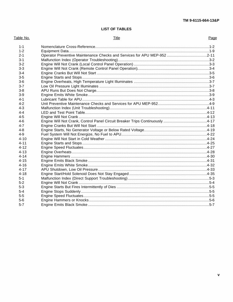
LIST OF TABLES
Table No. Title Page
1-1 Nomenclature Cross-Reference....................................................................................................1-21-2 Equipment Data...........................................................................................................................1-92-1 Operator Preventive Maintenance Checks and Services for APU MEP-952 ...................................2-113-1 Malfunction Index (Operator Troubleshooting)................................................................................3-23-2 Engine Will Not Crank (Local Control Panel Operation) ..................................................................3-33-3 Engine Will Not Crank (Remote Control Panel Operation)...............................................................3-43-4 Engine Cranks But Will Not Start ..................................................................................................3-53-5 Engine Starts and Stops ...............................................................................................................3-63-6 Engine Overheats, High Temperature Light Illuminates ..................................................................3-73-7 Low Oil Pressure Light Illuminates ................................................................................................3-73-8 APU Runs But Does Not Charge...................................................................................................3-83-9 Engine Emits White Smoke..........................................................................................................3-94-1 Lubricant Table for APU ...............................................................................................................4-34-2 Unit Preventive Maintenance Checks and Services for APU MEP-952.............................................4-94-3 Malfunction Index (Unit Troubleshooting).....................................................................................4-114-4 LED and Test Point Table...........................................................................................................4-124-5 Engine Will Not Crank ................................................................................................................4-134-6 Engine Will Not Crank, Control Panel Circuit Breaker Trips Continuously ......................................4-174-7 Engine Cranks But Will Not Start ................................................................................................4-184-8 Engine Starts, No Generator Voltage or Below Rated Voltage.......................................................4-194-9 Fuel System Will Not Energize, No Fuel to APU...........................................................................4-224-10 Engine Will Not Start in Cold Weather .........................................................................................4-244-11 Engine Starts and Stops .............................................................................................................4-254-12 Engine Speed Fluctuates............................................................................................................4-274-13 Engine Overheats ......................................................................................................................4-284-14 Engine Hammers .......................................................................................................................4-304-15 Engine Emits Black Smoke ........................................................................................................4-314-16 Engine Emits White Smoke........................................................................................................4-324-17 APU Shutdown, Low Oil Pressure ...............................................................................................4-334-18 Engine Start/Hold Solenoid Does Not Stay Engaged ....................................................................4-355-1 Malfunction Index (Direct Support Troubleshooting) .......................................................................5-35-2 Engine Will Not Crank ..................................................................................................................5-45-3 Engine Starts But Fires Intermittently of Dies .................................................................................5-55-4 Engine Stops Suddenly ................................................................................................................5-55-5 Engine Speed Fluctuates..............................................................................................................5-55-6 Engine Hammers or Knocks .........................................................................................................5-65-7 Engine Emits Black Smoke ..........................................................................................................5-7
v

TM 9-6115-664-13&P
How to Use This Manual
1. DESCRIPTION OF THE MANUAL.
a. Front Cover Index. The front cover of this manual contains an index to allow for quick and easy access to themost frequently used sections of the manual. This index is located along the right side of the cover. The boxed sectionheadings on the cover match boxed section headings in the Table of Contents (see page i).
b. Each box on the front cover has a black tab on the right. This tab lines up with a matching tab on the first page ofthe indexed section. To locate the section you're looking for, match the black tabs and open to that page in the manual.
c. Chapter Organization. This manual has five chapters covering; introductory information, operating instructions,operator maintenance procedures, unit maintenance instructions, and direct support maintenance instructions. Eachchapter is divided into sections. These sections contain the operation, cleaning, inspection, troubleshooting, and repairtasks appropriate for the specific maintenance level.
(1) Chapter 1 - Introduction. Chapter 1 contains general information, equipment description, and technicalprinciples of operation.
(2) Chapter 2 - Operating Instructions. Chapter 2 contains a description of APU controls and indicators. Thelocal and remote control panel assemblies are illustrated and each control and indicator is described in atable. Operating procedures are detailed, including operator level Preventive Maintenance Checks andServices (PMCS), operation under usual conditions, and operation under unusual conditions.
(3) Chapter 3 - Operator Maintenance Instructions. Chapter 3 contains the maintenance proceduresauthorized at the operator level. Included are troubleshooting procedures useful in recognizing APUmalfunctions, tests and inspections, and corrective actions.
(4) Chapter 4 - Unit Maintenance Instructions. Chapter 4 contains unit level maintenance instructions,including servicing, PMCS, troubleshooting, and unit level corrective maintenance.
(5) Chapter 5 - Direct Support Maintenance Instructions. Chapter 5 contains direct support level maintenanceinstructions, including troubleshooting and direct support level corrective maintenance.
d. Paragraph and Task Numbering. All paragraphs and maintenance tasks are numbered. This helps you findwhat you need when you need it. Use the Table of Contents (page i) or alphabetical index (at the back of the manual) tofind the paragraph or task you need.
e. Appendices. The appendices in this manual contain both general maintenance information and specific data forthis generator set. They list reference manuals and materials, components of the generator set, additional authorizationlist items, repair parts and special tools, expendable supplies and materials, lubrication instructions, torque limits, andmandatory replacement parts. Refer to the Table of Contents (page ii) for a complete list of the appendices used in thismanual.
vi

TM 9-6115-664-13&P
2. HOW TO FIX A GENERATOR SET MALFUNCTION.
a. Determining the Cause. Figuring out the cause of the malfunction, or troubleshooting, is the first step in fixingthe generator set and returning it to operation. Follow these steps to determine the root of your problem:
(1) Turn to the Table of Contents section in this manual (page i).
(2) Locate "Troubleshooting" for your maintenance level and turn to the page indicated.
(3) In the Troubleshooting section, find the troubleshooting logic tree for the component affected by themalfunction. Refer to the Symptom Index for help.
NOTE
If the specific symptom is not addressed, the maintenance required is most likelymore detailed than authorized for your level. Notify personnel at a highermaintenance level.
(4) Begin troubleshooting at the box on top of the page. Carefully work your way down through thetroubleshooting tree to try and determine what the problem is.
(5) Once the trouble has been determined, go to the maintenance task called out in the logic tree. Remedy themalfunction, test the generator set, and return it to service.
b. Preparing for a Task.
NOTE
You must familiarize yourself with the entire maintenance procedure beforestarting any maintenance task. Ensure all parts, materials, and tools are available.Read through all steps before beginning.
(1) PAY ATTENTION TO WARNINGS, CAUTIONS, AND NOTES.
(2) Maintenance tasks are arranged in a logical disassembly/assembly sequence and address only thecomponent or assembly to be replaced. Locator illustrations are included for removal and installation.These illustrations show you the area of the generator set to be worked on.
(3) All mandatory replacement parts are listed, including gaskets, packings, cotter pins, and lockwashers.They are listed by the Repair Parts and Special Tools List (RPSTL) name. Expendable supplies andsupport materials are listed, including solvents, rags, grease, and safety wire.
(4) Tools, tool kits or shop sets needed to do the task are listed. If tools from a repairman's kit are needed, thekit is listed. Tools that are not in a kit or set are listed by name, type, and size. Special tools and testequipment are listed by part number.
vii

TM 9-6115-664-13&P
(5) Related TM's needed to accomplish the task are listed. The steps tell when these TM's are needed.
(6) Read the entire task carefully before starting. DO NOT START A TASK UNTIL:
You know what replacement parts, tools, and supplies are needed
You have the things you need
You understand what to do
You know all applicable safety hazards, warnings, cautions, and risks
c. How To Do The Task. Before starting, read the entire task. Familiarize yourself with the entire procedure beforeyou begin the task. The following are considered standard maintenance practices. Instructions about these practices willnot normally be included in the task steps. Task steps will tell you when standard maintenance practices do not apply. Asyou read, remember the following:
(1) Electrical wiring shall be tagged before it is disconnected.
(2) Used packings, retainers, gaskets, cotter pins, lockwashers, and safety wire shall be discarded. Do notreuse. New parts shall be installed.
(3) Packings shall be coated with lubricant before installation in accordance with task instructions.
(4) Disassembly procedures list all steps required to support total authorized repair of a component. You maynot need to disassemble a part as far as described in the task. Follow the steps to disassemble as far asrequired to replace worn or damaged parts.
(5) Before components or the disassembled parts of a component are inspected, they shall be cleaned asrequired.
(6) Components and mating surface areas shall be inspected for serviceable condition before installation.
(7) When a nut is tightened or loosened on a bolt, the bolt head shall be held with a wrench.
(8) A special torque will be cited when the words TORQUE TO are used in the task. Standard torques areused at all other times. Refer to the Torque Limit appendix for information.
(9) When tightening hardware, observe compliance with the drag torque as required. To determine dragtorque, thread nut onto bolt until at least two threads protrude. The nut shall not contact the mating part.The torque required to begin turning the nut is the drag torque.
(10) When a cotter pin is required, cotter pin holes will be aligned within the allowable torque range.
(11) After maintenance, inspect for foreign objects.
viii

TM 9-6115-664-13&P
NOTE
This manual is divided by maintenance level (operator, unit, and direct support). Ifyou cannot find a generator set malfunction in the troubleshooting section for yourmaintenance level, or cannot find the appropriate corrective actions in themaintenance section, notify personnel at next higher maintenance level.
3. REPAIR PARTS AND SPECIAL TOOLS LIST.
A Repair Parts and Special Tools List (RPSTL) is included as Appendix G to this manual. The RPSTL containsexploded view illustrations and parts lists keyed to the illustrations. It lists part number, part name, and quantity used ineach application. Use the RPSTL to identify and order replacement parts. Refer to Appendix G for detailed informationon how to use the RPSTL.
ix

TM 9-6115-664-13&P
1. Enclosure Assy2. Local Control Panel Assy3. Remote Control Panel4. Fuel Module5. Engine Exhaust System6. Engine7. Alternator8. Oil Cooler9. Lifting Device10. Cross Member11. Tie-Down Ring12. Nose Piece13. Lid14. Lid Latch15. Oil Filter Access Door16. Engine Valve Access Door17. Exhaust Cover18. Internal Exhaust Assembly19. NATO Receptacle20. Fuel Fitting21. Cooling Air Inlet Duct22. Warm Air Outlet Duct
Figure 1-1. 5kW, 28VDC, Diesel Engine Driven Auxiliary Power Unit (APU)
1-0

TM 9-6115-664-13&P
CHAPTER 1INTRODUCTION
Section I. GENERAL INFORMATION
1-1. SCOPE.
This manual provides instructions on operation, troubleshooting, and maintenance of the 5kW, 28VDC, DieselEngine Driven Auxiliary Power Supply (APU), MEP-952B, NSN 6115-01-452-6513. Information is provided on principlesof operation, controls and indicators, preventive maintenance checks and services, lubrication, operation under both localand remote conditions, troubleshooting, and maintenance. Refer to Figure 1-1 for full view illustrations of the APUshowing features pertinent to the operator.
1-2. MAINTENANCE FORMS AND RECORDS.
Department of the Army forms and procedures used for equipment maintenance will be those described by DA Pam738-750, The Army Maintenance Management System (TAMMS).
1-3. CORROSION PREVENTION AND CONTROL (CPC).
a. Corrosion Prevention and Control (CPC) of Army materiel is a continuing concern. It is important that anycorrosion problems with the APU be reported so that the problem can be corrected and improvements can be made toprevent the problem in future APUs.
b. While corrosion is typically associated with rusting of metals, it can also include deterioration of other materials,such as rubber or plastic. Unusual cracking, softening, swelling, or breaking of these materials may be a corrosionproblem.
c. If a corrosion problem is identified, it can be reported using Standard Form 368, Product Quality DeficiencyReport. Use of keywords such as "corrosion", "rust", "deterioration", or "cracking" will ensure that the information isidentified as a CPC problem.
d. Submit Form 368 to the address specified in DA Pam 738-750.
1-4. DESTRUCTION OF ARMY MATERIAL TO PREVENT ENEMY USE.
For destruction of Army material to prevent enemy use, refer to TM 750-244-3.
1-5. REPORTING EQUIPMENT IMPROVEMENT RECOMMENDATIONS (EIR's).
If your APU needs improvement, let us know. Send us an EIR. You are the only one who can tell us what you don'tlike about your equipment. Put it on a SF 368 (Product Quality Deficiency Report). Mail it to: Commander, US ArmyCommunications and Electronics Command (CECOM), Customer Feedback Office, ATTN: AMSEL-LC-LEO-D-CS-CFO,Fort Monmouth, NJ 07703-5000. We will send you a reply.
1-6. WARRANTY INSTRUCTIONS
The 5 kW 28VDC APU contains two components covered by warranty. The engine has a one year warranty fromthe date of manufacture of the generator set. The generator set manufacturing date is located on the generator setdataplate. The alternator and regulator have a one year warranty from their date of Niehoff manufacture. The date ofmanufacture is located on a dataplate attached to the alternator/voltage regulator.
To submit a warranty claim, fill out a Product Quality Deficiency Report, SF368, as per DA PAM 738-750. Be sureto include the dates from the applicable data plates and check 'Yes' in block 19, Item under warranty. Hold the defectivepart until disposition instructions are provided.
1-1

TM 9-6115-664-13&P
1-7. NOMENCLATURE CROSS-REFERENCE LIST.
Shortened nomenclature is used in this manual to make procedures easier for you to read. A cross-referencebetween the shortened nomenclature and the official nomenclature is shown in Table 1-1.
Table 1-1. Nomenclature Cross-Reference
Common Name Official NomenclatureAPU 5kW, 28VDC, Diesel Engine Driven Auxiliary Power Unit,
MEP-952B, NSN 6115-01-452-6513
1-8. LIST OF ABBREVIATIONS.
All abbreviations used in this manual are found in MIL-STD-12.
1-2

TM 9-6115-664-13&P
Section II. EQUIPMENT DESCRIPTION
1-8. EQUIPMENT CHARACTERISTICS.
• 5 Kilowatt, 28 Volts Direct Current, Auxiliary Power Unit (APU)
• Shock-mounted in an aluminum enclosure
• Front mounting brackets bolt to APU enclosure
• Rear mounting brackets welded to APU enclosure
• Two service lids on top of enclosure, two engine service doors on sides of enclosure
• Single point lifting provision on top of enclosure
• Fan-baffle, beltless cooling system
• Single cylinder, air fin cooled, horizontal heavy duty diesel engine
• Negative ground, brushless 6-phase externally energized and self-rectifying alternator
1-9. CAPABILITIES AND FEATURES.
• 3000 RPM operating speed
• 5.0 Kilowatt, 28 VDC, 180 Amp rated output at 4000 feet altitude, 95ºF (15 HP maximum)
• Rated engine horsepower of 15 HP continuous at 3000 RPM
• Output is 28 VDC, 3000 RPM
• Equipped with a 28 VDC NATO slave receptacle
• Audio noise rating of less than 70 dBA at 23 feet from enclosure, 85 dBA at operator's control panel
• Engine equipped with hand-start (manual crank) capability
• Engine shutdown of 30 seconds, maximum
• Weight 580 pounds, dimensions 34.5 x 30.5 x 17.0 inches
• Local and remote control of APU operations
1-3

TM 9-6115-664-13&P
1-10. LOCATION AND DESCRIPTION OF MAJOR COMPONENTS (FIGURE 1-1).
a. The 5kW, 28VDC, Diesel Engine Driven Auxiliary Power Unit, MEP-952B, hereafter referred to as APU, isdesigned to mount on the U.S. Army M1068 tracked vehicle. The APU provides alternate power to the vehicle. The APUis also capable of remote operation, detached from the vehicle.
b. The APU consists of an aluminum enclosure assembly (1, Figure 1-1), local control panel assembly (2), remotecontrol panel assembly (3), fuel module (4), engine exhaust and silencer system (5), single-cylinder diesel engine (6), 6phase brushless alternator (7), engine oil cooler (8), and associated wiring harnesses, electrical connectors, and fuelhoses. Two detachable mounting brackets are secured to the front sides of the APU enclosure. Two vertical mountingbrackets are welded to the rear comers of the enclosure. These brackets are used to secure the APU to the M1068vehicle.
c. Enclosure Assembly. The enclosure assembly (1, Figure 1-1) supports and protects all APU components.The enclosure housing is a one-piece aluminum structure and forms the front, back, sides, and base of the enclosureassembly. A single point lifting device (9) is mounted to the top-center cross member (10). Four tie-down rings (11) aremounted on the enclosure, two on the nose piece (12) and two on the rear housing panel.
d. Two liftable lids (13) are mounted to the top of the of the enclosure assembly. Fold-down latches (14) securethe lids in place during vehicle operation. The lids allow easy access to APU components for inspection, servicing, andmaintenance tasks. The lids and top-center cross member (10) may be removed as an assembly, allowing fast and easyremoval/replacement of the engine and alternator. Two hinged doors (15, 16) located on the sides of the enclosure permitquick access to the engine. The engine oil filter door (15) opens to allow access to the engine oil filter, engine oil cooler,and related hoses. The engine valve access door (16) allows access to the engine rocker box and cylinder head foradjustment procedures.
e. A slanted nose piece (12) is attached to the front of the enclosure. The nose piece deflects foreign objects thatmay come up the front of the vehicle, protecting the APU. A hole in the nose piece allows for insertion of the engine crankhandle, permitting manual start of the engine if required. The oil cooling fan is mounted to the enclosure housing frontpanel, behind the nose piece.
f. A metal exhaust cover (17) is mounted to the left side of the enclosure. The cover protects the exhaust silencer(18) and exhaust pipe, and prevent personnel from touching hot exhaust components. The cover is closed on the bottomto ensure that all hot exhaust air escapes upward. A NATO electrical receptacle (19) and fuel fitting (20) are accessedthrough recesses located to the left of the exhaust cover.
g. A cooling air inlet duct (21) is located under the enclosure housing. Two warm air outlet ducts (22) are locatedon the sides of the enclosure. Each outlet duct is baffled. The inside of the enclosure and underside of the access lidsare covered with sound-proofing material to reduce noise.
1-4

TM 9-6115-664-13&P
h. Local Control Panel Assembly. The local control panel assembly (2, Figure 1-1) is mounted at the right rearcorner of the enclosure assembly and contains all the control devices required to operate the APU. The local controlpanel allows the operator to start and run the APU, transfer control to the remote control panel assembly (3), and stop theAPU in the local or remote operating mode.
i. The local control panel assembly consists of a START / PRIME RUN / OFF switch, PREHEAT switch, APU ONswitch, LOCAL / REMOTE switch, REMOTE panel cable connector receptacle, three APU electrical test points, 5 LEDindicator light, a printed circuit board, and associated breakers, relays, and connectors. The control panel enclosureforms a water-resistant shield for internal components. One electrical receptacle on the rear of the panel connects thepanel to the APU wiring harness.
j. The control panel may be removed from the enclosure assembly as a unit, allowing for easy maintenance.Refer to Description and Use of Operator's Controls and Indicators (Chapter 2) for detailed information on control panelassembly components.
k. Remote Control Panel. The remote control panel (Figure 1-1) allows for operation of the APU from inside ofthe vehicle. The remote control panel consists of a DC voltmeter, START / PRIME RUN / OFF switch, PREHEAT switch,BATTLE SHORT OFF switch, APU ON switch, EMERGENCY STOP push-button, a printed circuit board, and associatedconnectors. LED indicator lights are used to indicate the following conditions; APU ON, battle short ON, HIGH ENGINETEMPERATURE, and LOW OIL PRESSURE. LEDs are tested using a PRESS TO TEST LAMPS switch, located on theremote panel.
l. An eight (8) foot interconnect cable connects the APU local control panel to the remote control panel. Refer toDescription and Use of Operator's Controls and Indicators (Chapter 2) for detailed information on remote control panelassembly components.
m. Fuel System and Fuel Module. APU fuel system components are housed within a removable fuel module(Figure 1-2). The fuel module consists of an inlet fuel fitting (1), fuel filter water separator (2), electric fuel pump (3), fuelfloat valve assembly (4), and related hoses and fittings.
n. The module is fitted with a removable cover (5) for ease of maintenance and may be removed as a unit from theAPU enclosure. The module cover is equipped with three slide latches that secure the cover during unit operation. A holein the module cover moderates air temperature, keeping the temperature within the module cooler than the temperaturewithin the rest of the APU enclosure.
o. Fuel for operation of the APU is supplied to the fuel module from the vehicle by way of a fuel interface hose.The APU may also be operated from an external fuel supply utilizing the same inlet fuel fitting (1). A fuel supply line (6)passes fuel from the fuel filter water separator (2), through an in-line fuel filter (7), to the engine fuel pump. A fuel returnline (8) directs fuel from the engine fuel injector line to the fuel float valve assembly (4).
p. The fuel module also houses the NATO electrical receptacle (9), contactor, and related wiring and terminals thatcontrol power output to the vehicle.
1-5

TM 9-6115-664-13&P
1. Fuel Fitting2. Fuel Filter Water Separator3. Electric Fuel Pump4. Fuel Float Valve Assy5. Fuel Module Cover6. Fuel Supply Line7. In-Line Fuel Filter8. Fuel Return Line9. NATO Receptacle
Figure 1-2. Fuel System Components
q. Engine Cooling and Exhaust System. The engine cooling and exhaust system (Figure 1-3) draws cool airinto the APU for purposes of cooling the engine and alternator, and forces warm air and exhaust fumes from theenclosure to the atmosphere. The cooling system consists of a twin fan (1) mounted to the alternator (2), an air inlet duct(3) located in the base of the enclosure, engine air inlet hose (4), engine air filter (5), and engine air outlet baffle (6).
r. The engine exhaust system consists of an engine muffler/silencer (8), mounted to the engine exhaust port, andexhaust piping (9). An exhaust cover (10) attached to the side of the APU enclosure provides protection for the silencerand exhaust piping. A rain cap on top of the exhaust piping prevents rain from entering. The cover is closed on thebottom to ensure that all hot exhaust air escapes upward, and padded with sound-proofing material.
s. An engine oil cooler (11) is mounted to the inside of the enclosure. An electric fan (12) is mounted directly infront of the oil cooler and forces cool air across the oil cooler tubes. Warm air exits through a small air outlet baffle (13),located on the side of the enclosure.
1-6

TM 9-6115-664-13&P
1. Twin Fan2. Alternator3. Air Inlet Duct4. Air Inlet Hose5. Engine Air Filter6. Air Outlet Baffle7. Thermostat8. Engine Silencer9. Exhaust Piping10. Exhaust Cover11. Engine Oil Cooler12. Electric Fan13. Air Outlet Baffle14. Preheat Module
Figure 1-3. Cooling Air and Exhaust Components
t. Diesel Engine. The APU is equipped with a four cycle, single cylinder, air cooled, fuel injected, horizontalcylinder engine (Figure 1-4). It has a 95mm bore, a 100mm stroke, 709 cubic centimeter displacement, and has a ratedoutput of 15 horsepower at 3000 rpm. The engine fuel system consists of a solenoid (1), fuel injector assembly (2), fuelinjection pump (3), fuel feed pump (4), and associated fuel piping, hoses, and fittings.
u. The engine oil system consists of an oil level dipstick (5), oil glow plug pipe (6), engine oil filter (7), oil pressurevalve (8), oil pressure switch (9), oil drain valve assembly (10), and oil filler (11). The engine is equipped with a 24 voltstarter motor (12) and an alternator assembly (13). A dry air filter assembly (14) is mounted to the top of the engine. Aspeed control assembly (15) regulates engine rpm. A one piece flywheel housing (16) protects the engine flywheel andcovers the area of engine/alternator connection.
v. Alternator. The APU uses a brushless, six phase, negative ground, externally energized, and selfrectifyingalternator (17, Figure 1-4). The alternator is supplied with an external, solid state regulator with flat temperaturecompensation (18), a twin fan assembly (20), and fan guard (21).
w. The engine and alternator are connected by a flexible rubber coupling and drive assembly. Four mounting feet(22) and a mounting bracket (19) secure the assembled engine-alternator to the enclosure base.
1-7

TM 9-6115-664-13&P
1. Solenoid 7. Engine Oil Filter 13. Alternator Assy 18. Voltage Regulator2. Fuel injector Assy 8. Oil Pressure Valve 14. Air Filter Assy 19. Mounting Bracket3. Fuel Inject. Pump 9. Oil Pressure Switch 15. Speed Control 20. Twin Fan Assy4. Fuel Feed Pump 10. Oil Drain Valve Assy 21. Fan Guard5. Oil Level Dipstick 11. Oil Filler 16. Flywheel Housing 22. Mounting Feet6. Oil Glow Plug 12. Starter Motor 17. Alternator
Figure 1-4. Engine and Alternator Components
1-8

TM 9-6115-664-13&P
1-11. EQUIPMENT DATA.
Refer to Table 1-2, Equipment Data, for a summary of specific capabilities, limitations, and critical data for operationand maintenance of the APU
Table 1-2. Equipment Data
WEIGHTS AND DIMENSIONS
Weight 580 lbs (263 Kg)Length 38.0 in. (96.5 cm)Width 30.5 in. (77.7 cm)Height 17.0 in. (43.2 cm)
GENERAL SPECIFICATIONS
Output Power Source 28 VDC NATO Slave ReceptacleRated Voltage, Current 28 VDC, 180 ampsAudio Noise Rating Less than 70 dBA at 23 feet (7 meters) from
perimeter of set, 3.9 feet (1.2 meters)above ground
85 dBA at operator's panelFuel Requirements MIL-F-46162 diesel fuel; VV-F-800, Type
DF-1, DF-2, or DF-A; MIL-T-83133turbine fuel, JP8
Auxiliary Fuel System Supplied from vehicle
TRANSPORTATION
Manual Transport Central lifting pointTruck, Rail, Air and Trailer Transport Tiedown rings providedInclined Transport (Angle) 27 degrees maximum, in any direction
PERFORMANCE CHARACTERISTICS
APU
Kilowatt Capacity at Altitude/Temperature1000 ft. (718.1 mm hg) at 107 degrees F 5.5 kilowatts4000 ft. (656.3 mm hg) at 95 degrees F 5.0 kilowatts
Output Terminal NATO Slave (MS52131)
1-9

TM 9-6115-664-13&P
Table 1-2. Equipment Data (continued)
PERFORMANCE CHARACTERISTICS
Diesel Engine
Horsepower 15 at 3000 rpmHorsepower Derating at Altitude/Temperature
1000 ft. at 107 degrees F 13.354000 ft. at 95 degrees F 12.458000 ft. at 95 degrees F 10.35
Operating RPM 3000 rpmPre-Heat Time 10 minutes oil, 2 minutes airEngine Shutdown 60 seconds maximumEngine Cooling System Air, fin cooledOil Type MIL-L-2104, 15W-40 (0 to +120º F)
MIL-L-46167, 5W-30 (-25 to +15° F)Engine Oil Capacity 0.70 gallon (2.6 liters)Oil Sump Capacity 0.55 gallon (2.1 liters)Bore 3.75 inches (95 mm)Stroke 3.94 inches (100 mm)Cylinder SingleDisplacement 290 cubic inches (738 cubic cm)Compression Ratio 19:1Torque 27.4 ft-lbs (37 Nm) at 2000 rpmFuel Consumption at 5.0 kW 8.8 ounces (250 grams) per kW hourOil Consumption at 5.0 kW 0.04 ounces (1.0 gram) per kW hour
Alternator
Operating RPM 3000 rpm nominal, 8000 maximumOverspeed 10,000 rpmRotor Inertia With Fan 80 lbs/square in. (234 Kg/square cm)Output 180 amp, 28 VDC at 3000 rpm,
1000 feet altitudeEfficiency 75 to 68% over normal operating rangeOperating Temperature (ambient) -25 to +120° F
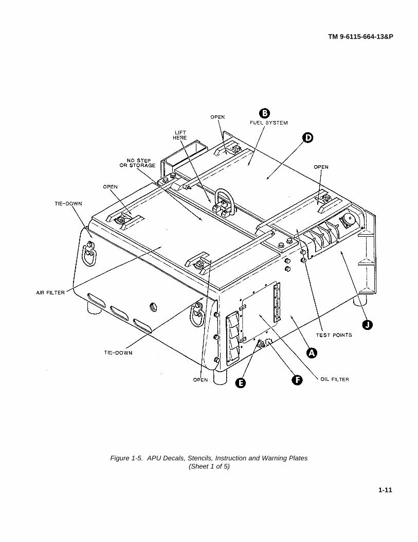
1-12. APU DECALS, STENCILS, IDENTIFICATION AND WARNING PLATES.
Figure 1-5 illustrates all decals, stencils, identification plates, operating instruction plates, and warning plates foundon the APU.
1-10
(Figure 1-5 sheet 1 of 5)(Figure 1-5 sheet 2 of 5)(Figure 1-5 sheet 3 of 5)(Figure 1-5 sheet 4 of 5)(Figure 1-5 sheet 5 of 5)
TM 9-6115-664-13&P
Figure 1-5. APU Decals, Stencils, Instruction and Warning Plates(Sheet 1 of 5)
1-11

TM 9-6115-664-13&P
Figure 1-5. APU Decals, Stencils, Instruction and Warning Plates(Sheet 2 of 5)
1-12

TM 9-6115-664-13&P
Figure 1-5. APU Decals, Stencils, Instruction and Warning Plates(Sheet 3 of 5)
1-13

TM 9-6115-664-13&P
D
OPERATING INSTRUCTIONS
WARNING!!!
TO AVOID SHOCK HAZARD, BE SURE THAT THE APUIS PROPERLY GROUNDED BEFORE OPERATING
PROPER GROUNDING IS ACHIEVED THROUGH THESLAVE/OUTPUT CABLE WHEN THE APU IS ON THE VEHICLE.
1. VERIFY SLAVE /OUTPUT CABLE AND FUEL INTERFACE ARE CONNECTED TO THE VEHICLE.
2. CHECK THE ENGINE OIL LEVEL AND ADD IF NECESSARY. ENGINE CAPACITY IS 2.5 QUARTS OF MIL-L-2104 OIL UNDER NORMAL CONDITIONS. UNDER CONDITIONS AT OR BELOW -15ºF (-26ºC), USE MIL-L-46167 ARCTIC OIL.
3. VERIFY THE "LOCAL/REMOTE" SWITCH IS IN THE "LOCAL" POSITION FOR OPERATION AT THE APU, IFREMOTE OPERATION IS DESIRED, MOVE THE SWITCH INTO THE "REMOTE" POSITION.
4. MOVE THE APU CONTROL SWITCH INTO THE "PRIME/RUN"' POSITION.
5. UNDER NORMAL CONDITIONS, MOVE THE "START/RUN PRIME SWITCH INTO THE "START' POSITION ANDHOLD UNTIL THE ENGINE STARTS. THEN RELEASE THE SWITCH.
6. UNDER CONDITIONS AT OR BELOW 32ºF (0ºC), OPERATE THE PREHEAT SWITCH AS NEEDED TOFACILITATE STARTING, PRIOR TO STEP 5.
7. TO STOP THE APU, MOVE THE START/RUN/PRIME SWITCH IN-TO THE OFF POSITION.
8. IN AN EMERGENCY, DEPRESS THE "EMERGENCY STOP" BUTTON LOCATED ON THE REMOTE PANEL.
Figure 1-5. APU Decals, Stencils, Instruction and Warning Plates(Sheet 4 of 5)
1-14

TM 9-6115-664-13&P
Figure 1-5. APU Decals, Stencils, Instruction and Warning Plates(Sheet 5 of 5)
1-15

TM 9-6115-664-13&P
Section III. PRINCIPLES OF OPERATION
1-13. PRINCIPLES OF OPERATION.
The theory behind the operation of the APU is described in the following paragraphs. Each APU system isdependant upon the other for efficient operation. The information contained here will assist operators, as well as unit anddirect support maintenance personnel in understanding how the APU functions. This knowledge will assist in isolatingcomponents which have failed. Refer to the Electrical Schematic (Figure FO-1) found at the end of this manual.
1-14. ELECTRICAL SYSTEM.
a. The APU operates on a 28 volt direct current (DC) electrical system. The DC system provides power to APUcontrol circuitry, relay logic, and engine cranking, as well as producing voltage for load application. There are 3 test pointsand 5 LED troubleshooting lights located on the local control panel. There are 4 LED lights located on the remote controlpanel. There are 2 LED lights located on the preheat module box. These test points and LEDs provide malfunctionisolation for critical components of the APU.
b. The DC system is powered by a 24 VDC battery located in the vehicle. The battery is charged by the APUoutput when the APU is running and the APU ON switch (A1-S4) is placed in the ON position. The APU is groundedthrough connection to the vehicle by being bolted to the chassis as well as through the NATO connector.
c. Engine cranking is initiated by placing the START / PRIME RUN / OFF switch (A1-S4) in the PRIME RUNposition. In this position, switch A1-S4 applies voltage to the following components and circuits:
• Fuel pump, which primes the fuel system• Preheat module
d. Switch A1-S4 is placed in the PRIME RUN position for a few seconds to allow the APU fuel system to prime.Once the fuel system has primed, the operator moves switch A1-S4 to the START position. Voltage is applied to thepreheat module via relay A1-K3. This supplies power to the starter solenoid, oil snap switch (located on the oil filteradapter), and relay A2-A1-K2, which applies voltage to the pull coil for one second. Relay A1-K3 also overrides relay A1-K2, which controls the engine malfunction safety shutdowns (low oil pressure and high engine temperature).
e. The action on relay A1-K2 allows the engine start solenoid to stay latched during the start cycle. When theSTART / PRIME RUN / OFF switch is released to the PRIME RUN position, A1-K2 remains energized (providing nomalfunctions exist).
f. When the engine reaches rated speed, the operator must momentarily move the APU ON switch (A1S3) to theON position, then release the switch. This energizes latching relay A1-K1. This sends a signal to turn on the alternatorand close the contactor. At this time the starter lockout circuit is also energized.
1-16

TM 9-6115-664-13&P
1-15. ENGINE PREHEATING.
If ambient temperature drops below 32º F, the engine PREHEAT switch (A1-S2) should be activated before theengine is cranked. Placing the PREHEAT switch in the OIL (up) position energizes relay A2-K3, providing power to the oilglow plug located in the oil reservoir of the engine. Placing the PREHEAT switch in the AIR (down) position energizesrelay A2-K4, providing power to two air glow plugs located in the engine intake manifold. The PREHEAT switch is springloaded and will return to the off position when released.
1-16. EMERGENCY STOP SWITCH.
When the remote control panel EMERGENCY STOP switch (A4-S3) is pushed in, it removes 28 VDC power fromthe fuel solenoid and causes the engine to stop. While the EMERGENCY STOP switch is activated, power is removedfrom the starter solenoid and the engine cannot be cranked. The switch must be pulled out to the off position before theengine can be started again and circuitry functions return to normal.
1-17. MALFUNCTION INDICATORS.
a. If the engine exceeds normal operating temperature, a heat sensitive, high cylinder head temperature switch(HT) closes. The circuitry removes ground from relay A1-K2, causing power to be removed from the fuel solenoid holdcoil. A red HIGH ENGINE TEMPERATURE LED (A4-LED 4, located on the remote control panel) illuminates.
b. If engine oil pressure drops below a safe operating level, a low oil pressure switch (OP) opens. The circuitryremoves ground from relay A1-K2, causing power to be removed from the fuel solenoid hold coil. A red LOW OILPRESSURE LED (A4-LED 3, located on the remote control panel) illuminates.
1-18. REMOTE OPERATION.
a. The APU may be operated using a remote control panel supplied with the system. The operator places bothSTART / PRIME RUN / OFF switches (local and remote control panels) in the OFF position. The REMOTE / LOCALswitch (A1-S1, located on the local control panel) is moved to the REMOTE position. The control of the APU is switchedto the remote control panel. Electrical operation of the APU is the same whether controlled from the local or remotecontrol panels. The remote control panel is equipped with a PRESS TO TEST LAMPS switch (A4-S6). When the switchis depressed, all LEDs shall illuminate, verifying that they are functioning properly.
b. The BATTLE SHORT switch (A4-S5, located on the remote control panel) overrides the shutdown systems ofthe APU (high engine temperature, low oil pressure). Placing the switch in the ON position sends a 28 VDC signal to thelocal control panel and energizes relay A1-K2, preventing engine shutdown in low oil or high temperature conditions.
1-19. FUEL SYSTEM.
a. The APU fuel system (Figure 1-6) is designed to interface with the vehicle and operate on the same fuels as thevehicle. The system is self venting and requires no fuel return line to the vehicle. The APU may be operated from anauxiliary fuel source up to twenty-five feet away using the auxiliary fuel line provided.
1-17

TM 9-6115-664-13&P
b. An electric fuel pump (1, Figure 1-6) draws fuel from the vehicle to the APU through an interface fuel line (2).The fuel passes through a fuel filter water separator (3), which removes contaminating micro particles and separateswater from the fuel flow. Water collects in the base of the fuel filter water separator and may be drained by turning a drainknob. The filtered fuel enters the electric fuel pump (1) and flows to a fuel float valve assembly (4). The float valve bowlholds six ounces of fuel to provide three minutes of APU run time. This three minute period allows the operator to switchfrom the vehicle fuel supply to an auxiliary fuel supply while the APU is operating. The float valve bowl also functions asthe fuel return location and de-aeration site. Fuel level is maintained in the bowl by means of the float valve.
c. Fuel flows from the fuel float valve assembly (4), out of the fuel module, and into a secondary in-line fuel filter(5). The in-line fuel filter is mounted on a bracket at the engine flywheel housing. Filtered fuel passes from the in-linefilter to the engine's mechanical fuel pump (6).
d. When the control panel START/PRIME RUN/OFF switch is placed in the START position, a start/stop solenoidis energized, allowing fuel to flow to the engine fuel injection pump (8). The fuel injection pump provides pressurized fuelto operate the engine fuel injector (7). The fuel circuit is completed when excess fuel is returned to the fuel float valveassembly (4).
1. Electric Fuel Pump 4. Fuel Float Valve Assy 7. Fuel Injector2. Interface Fuel Line 5. In-Line Fuel Filter 8. Fuel Injection Pump3. Fuel Filter Water Separator 6. Mechanical Fuel Pump
Figure 1-6. Fuel System Diagram
1-18

TM 9-6115-664-13&P
1-20. APU COOLING AND EXHAUST SYSTEM.
a. Air Cooling System. Cool air is drawn into the APU box by twin fans. Air enters the box through a duct (2,Figure 1-7) located in the base of the box. The air feeds the alternator (1) and engine flywheel, and air flows across thewindings and exits the box. The engine air flows thru the cylinder fins (3) and exits the box through the engine headaccess door (5). Additional cool air enters the box from ports (6) located behind the nose piece. This air is for box coolingand combustion air.
b. Engine Exhaust. Hot exhaust air and fumes are passed from the engine exhaust port to an engine silencer(9), through a curved exhaust pipe (10), and out to the atmosphere.
1. Alternator 6. Air Inlet Port 10. Exhaust Pipe2. Air Inlet Duct 7. Air Inlet Hose 11. Oil Filter Access Door3. Engine Cylinder Fins 8. Engine Air Filter 12. Ventilation Fan4. Air Duct Baffling 9. Engine Silencer 13. Engine Oil Cooler5. Engine Head Access Door
Figure 1-7. Cooling and Exhaust System
1-19

TM 9-6115-664-13&P
c. Engine Oil Cooling. A thermostatically controlled 24 VDC ventilation fan (12) is mounted to the enclosurebehind the nose piece. The fan blows cool air through the engine oil cooler (13), which is mounted directly in front of thefan. Engine oil circulates from the oil filter housing and through the oil cooler by means of the engine's mechanical oilpump. The thermostat for the fan is mounted on the oil cooler and activates the fan when oil temperature in the oil coolerreaches 140º F. The air generated by the fan flows through the oil cooler and exits the enclosure through an outlet baffle,located next to the engine oil filter access door (11).
1-21. ENGINE STARTING SYSTEM.
a. Engine start-up is controlled by the engine starter motor (Figure 1-8). When the coil-type starter solenoid (2) isenergized, magnetic force pulls the solenoid plunger in. The plunger is connected to a spring loaded engagement fork(1). This engagement fork pushes the drive pinion (5) out to engage the engine flywheel.
b. As the drive pinion (5) is pushed out, the armature (4) contacts the starter motor brushes (3), energizing thestarter's field winding. The starter motor will operate until the solenoid (2) is de-energized. Once deenergized, theengagement fork (1) will retract and the drive pinion will disengage from the engine flywheel.
1. Engagement Fork2. Starter Solenoid3. Motor Brushes4. Armature5. Drive Pinion
Figure 1-8. Engine Starter Motor
1-22. ENGINE COMBUSTION CYCLE.
a. The diesel engine combustion cycle can be divided into four separate strokes; compression stroke, powerstroke, exhaust stroke, and intake stroke. Thus the term four-stroke engine is applied to this type of unit.
b. Compression Stroke. During the compression stroke, the engine starter motor cranks the engine flywheel (1,Figure 1-9). The crankshaft (2) turns, forcing the piston (3) to rise to its highest point in the cylinder (4). The upwardmovement of the piston compresses air trapped inside the combustion chamber, causing temperature to rise over 932degrees F. A fine mist of fuel is sprayed into the combustion chamber by the fuel injector (5) just before the pistonreaches its high point. The compressed air and fuel mixture combusts.
1-20

TM 9-6115-664-13&P
c. Power Stroke . The combustion of the fuel and air mixture forces the piston (3) downward, turning thecrankshaft (2). The crankshaft is coupled to the alternator shaft and drives the alternator.
d. Exhaust Stroke. As the crankshaft (2) turns, it forces the piston (3) to again rise to its highest point. Once thepiston begins to rise, the exhaust valve (6) opens. Exhaust gases are forced out of the cylinder (4) as the piston rises.The exhaust valve closes just before the piston reaches its highest point.
e. Intake Stroke. As the piston (3) move downward, the inlet valve (7) opens. Air is drawn through the open inletvalve and into the cylinder (4). The inlet valve closes before the piston reaches the end of its stroke. The piston movesupward once more to repeat the combustion cycle.
f. Inlet and Exhaust Valve Operation. Inlet and exhaust valve (6, 7) movement is controlled by lobes on thecamshaft (8). As a camshaft lobe rotates, it forces a tappet (9) to rise, pushing upward on the mating push rod (10). Thepush rod forces the rocker arm (11) to rock, pressing down on the inlet/exhaust valve, forcing that valve to open. Airenters the chamber (inlet valve) or exhaust gases exit (exhaust valve) as appropriate.
1. Flywheel 5. Fuel Injector 9. Tappet2. Crankshaft 6. Exhaust Valve 10. Push Rod3. Piston 7. Inlet Valve 11. Rocker Arm4. Cylinder 8. Camshaft
Figure 1-9. Engine Combustion Cycle (Top View Cross Section)
1-21

TM 9-6115-664-13&P
1-23. ENGINE LUBRICATION.
a. Engine lubrication is controlled by a crankshaft driven oil pump. The oil pump is housed in the enginecrankcase (1, Figure 1-10) and supplies all oil to lubricate and cool high friction internal components. The crankcase actsas the oil sump, since a separate oil pan does not exist. The oil pump draws oil from the oil sump and passes it throughan oil filter element (2). After the oil passes through the element it is pumped through the engine oil cooler(13, Figure 1-7) and then to oil jackets to lubricate the crankshaft and camshaft bearings.
b. An oil pressure valve (3, Figure 1-10) relieves high pressure into the oil sump to prevent excessive build up ofoil pressure in the lubrication system. An oil pressure switch (4) (normally open) protects the engine from sudden loss ofoil pressure. Should pressure drop below the minimum required for safe operation, the oil pressure switch will close,cutting electrical power to the engine run/stop solenoid. Once oil pressure returns to normal, the oil pressure switch willopen. Engine oil level is monitored using an engine oil level dipstick (5). The engine is serviced at the engine oil filler port(6). An engine drain valve and hose assembly (7) allows the engine oil to be drained to a pan outside the APU enclosure.
1. Crankcase2. Oil Filter Element3. Oil Pressure Valve4. Oil Pressure Switch5. Oil Level Dipstick6. Oil Filler7. Oil Drain Valve and Hose
Figure 1-10. Engine Oil System
1-22
TM 9-6115-664-13&P
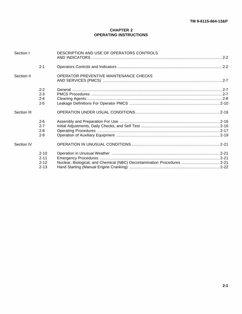
CHAPTER 2OPERATING INSTRUCTIONS
Section I DESCRIPTION AND USE OF OPERATORS CONTROLSAND INDICATORS .............................................................................................................. 2-2
2-1 Operators Controls and Indicators ........................................................................................ 2-2
Section II OPERATOR PREVENTIVE MAINTENANCE CHECKSAND SERVICES (PMCS) .................................................................................................... 2-7
2-2 General .............................................................................................................................. 2-72-3 PMCS Procedures .............................................................................................................. 2-72-4 Cleaning Agents .................................................................................................................. 2-82-5 Leakage Definitions For Operator PMCS ............................................................................ 2-10
Section III OPERATION UNDER USUAL CONDITIONS....................................................................... 2-16
2-6 Assembly and Preparation For Use .................................................................................... 2-162-7 Initial Adjustments, Daily Checks, and Self Test .................................................................. 2-162-8 Operating Procedures ....................................................................................................... 2-172-9 Operation of Auxiliary Equipment ....................................................................................... 2-19
Section IV OPERATION IN UNUSUAL CONDITIONS .......................................................................... 2-21
2-10 Operation in Unusual Weather ........................................................................................... 2-212-11 Emergency Procedures ..................................................................................................... 2-212-12 Nuclear, Biological, and Chemical (NBC) Decontamination Procedures ................................ 2-212-13 Hand Starting (Manual Engine Cranking) ............................................................................ 2-22
2-1

(Figure 2-1 Sheet 1 of 4)(Figure 2-1 Sheet 2 of 4)(Figure 2-1 Sheet 3 of 4)(Figure 2-1 Sheet 4 of 4)
TM 9-6115-664-13&P
Section I. DESCRIPTION AND USE OF OPERATORSCONTROLS AND INDICATORS
2-1. OPERATORS CONTROLS AND INDICATORS.
Prior to placing the APU into operation, personnel must be familiar with the location and function of all switches,controls, and indicators. Controls and indicators required for APU operation are identified in the following illustrations.
1 START / PRIME RUN / OFF Switch (A1-S4) Threeposition switch that controls APU operation.
START position activates engine starter. Springloaded. Must be held in place.
PRIME RUN position cuts electrical power tostarter. Energizes all circuits required for normaloperation. When unit is not running, fuel pumpis energized to prime fuel system.
OFF position cuts electrical power to the engineshutdown solenoid, causing APU shutdown.
2 PREHEAT OIL / AIR Switch (A1-S2) Activatesengine air or oil glow plugs for cold weather starts.Spring loaded.
3 APU ON Switch (A1 -S3) Energizes latching relayA1-K1, turning on the alternator and closing thecontactor.
4 REMOTE / LOCAL Switch (A1-S1) Switchesoperation of APU from local control panel to remotecontrol panel.
5 REMOTE Panel Electrical Connector (A1-J2)Connection point for remote control panel electricalcable.
Figure 2-1. Controls and Indicators(Sheet 1 of 4)
2-2
TM 9-6115-664-13&P
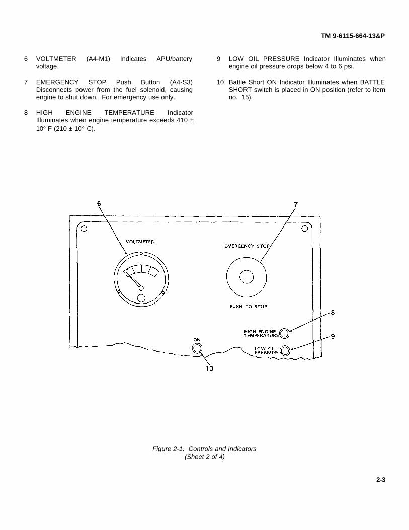
6 VOLTMETER (A4-M1) Indicates APU/batteryvoltage.
7 EMERGENCY STOP Push Button (A4-S3)Disconnects power from the fuel solenoid, causingengine to shut down. For emergency use only.
8 HIGH ENGINE TEMPERATURE IndicatorIlluminates when engine temperature exceeds 410 ±10° F (210 ± 10° C).
9 LOW OIL PRESSURE Indicator Illuminates whenengine oil pressure drops below 4 to 6 psi.
10 Battle Short ON Indicator Illuminates when BATTLESHORT switch is placed in ON position (refer to itemno. 15).
Figure 2-1. Controls and Indicators(Sheet 2 of 4)
2-3

TM 9-6115-664-13&P
11 START / PRIME RUN / OFF Switch (A4-S1) Threeposition switch that controls APU operation.
START position activates engine starter. Springloaded. Must be held in place.
PRIME - RUN position cuts electrical power tostarter. Energizes all circuits required for normaloperation. When unit is not running, fuel pumpis energized to prime fuel system.
OFF position cuts electrical power to the engineshutdown solenoid, causing APU shutdown.
12 APU ON Indicator Illuminates when APU contactor isclosed.
13 PRESS TO TEST LAMPS Push Button (A4-S6)Tests remote control panel indicator lights for properoperation.
14 APU ON Switch (A4-S4) Energizes latching relayA1-K3, turning on the alternator and closing thecontactor.
15 BATTLE SHORT Switch (S5) Placing switch in ONposition bypasses protective device shutdowncircuit. OFF position enables shut-down circuit tooperate.
16 PREHEAT OIL / AIR Switch (A4-S2) Activatesengine air or oil glow plugs for cold weather starts.Spring loaded.
17 AIR P.H. Indicator Located on preheat module.Illuminates when air heater elements are energized.
18 OIL P.H. Indicator Located on preheat module.Illuminates when oil heater elements are energized.
Figure 2-1. Controls and Indicators(Sheet 3 of 4)
2-4

TM 9-6115-664-13&P
19 Hourmeter Located on enclosure wall.Indicates hours of operation up to 9999.9hours. To view hour meter, look into enginecrank access hole (26) and to the right.
20 Manual Start Switch Allows for manual startof engine.
21 Engine Oil Level Dipstick Indicates amountof oil in engine oil sump (crankcase).
22 Engine Oil Filler Allows for addition ofengine oil.
23 Engine Oil Drain Valve and Plug Allows fordraining of engine oil.
24 Oil Pressure Switch Normally open. Shutsdown engine when engine oil pressuredrops below 4 to 6 psi.
25 Oil Pressure Valve Relieves high pressure inengine oil sump to prevent excessive buildup of oil pressure in lube system. Locatedbehind oil filter.
26 Engine Crank Access Hole Allows forinsertion of engine hand crank lever formanual start of engine.
27 RUN Indicator Illuminates when engine runsignal is sent to engine (START / PRIMERUN / OFF switch is in RUN position).
28 START Indicator Illuminates when engine iscranking (START PRIME RUN / OFF switchis in START position).
29 LOP (Low Oil Pressure) Indicator Illuminateswhen engine oil pressure drops below 4 to 6psi.
30 HT (High Temperature) Indicator Illuminateswhen engine temperature exceeds 410 ± 10F (210 ±10 C).
31 APU ON Indicator Illuminates when APUcontactor is closed.
32 NATO Receptacle Connection point forvehicle electrical power cable.
33 Fuel Fitting Connection point for vehicle fuelsupply line or auxiliary fuel supply.
34 Test Points (TP1-TP3) Used to test APU.
2-5

TM 9-6115-664-13&P
Figure 2-1. Controls and Indicators(Sheet 4 of 4)
2-6

TM 9-6115-664-13&P
Section II. OPERATOR PREVENTIVE MAINTENANCE CHECKSAND SERVICES (PMCS)
2-2. GENERAL.
Operator Preventive Maintenance Checks and Services (PMCS) means systematic caring, inspecting, and servicingof equipment to keep it in good condition and to prevent breakdowns. As the APU operator, your mission is to ensure thatthe APU is ready for operation at all times. It must be inspected so that defects may be discovered and corrected beforethey result in damage or failure.
a. Be sure to perform your PMCS each time you operate the APU. Always do your PMCS in the same order, so itgets to be a habit. Once you have had some practice, you will quickly spot anything wrong.
b. Do your BEFORE (B) PMCS before you operate the APU. Pay attention to WARNINGS, CAUTIONS, andNOTES.
c. Do your DURING PMCS while you operate the APU. Monitor the APU and its related components while it isactually being operated. Pay attention to WARNINGS, CAUTIONS, and NOTES.
d. Do your AFTER PMCS right after operating the APU. Pay attention to WARNINGS, CAUTIONS, and NOTES.
e. Do your WEEKLY PMCS once a week.
f. Use DA Form 2404 or 5988E (Equipment Inspection and Maintenance Worksheet) to record any faults youdiscover before, during, or after operation, unless you can fix them. DO NOT record faults that you fix.
g. Be prepared to assist unit maintenance when they lubricate the APU. Perform any other services whenrequired by unit maintenance.
2-3. PMCS PROCEDURES.
a. Your Preventive Maintenance Checks and Services, Table 2-1, lists inspections and care required to keep yourAPU in good operating condition. It is set up so you can make your BEFORE (B) OPERATION checks as you walkaround the APU.
b. The "INTERVAL" column of Table 2-1 tells you when to do a certain check or service.
c. The "PROCEDURE" column of Table 2-1 tells you how to do required checks and services. Carefully followthese instructions. If you do not have tools, or if the procedure tells you to, notify your supervisor.
NOTE
Terms "ready/available" and "mission capable" refer to same status: Equipment ison hand and ready to perform its combat missions. (See DA Pam 738-750).
d. The "NOT FULLY MISSION CAPABLE IF" column in Table 2-1 tells you when your APU is nonmission capableand why the APU cannot be used.
2-7

TM 9-6115-664-13&P
e. If the APU does not perform as required, refer to Chapter 3, Section II, Troubleshooting.
f. If anything looks wrong and you cannot fix it, write it on your DA Form 2404 or 5988E. IMMEDIATELY report itto your supervisor. If your equipment does not perform as required refer to Chapter 3, under Troubleshooting, for possibleproblems.
g. When you perform PMCS you will always need a rag or two. Following are checks that are common to theentire APU:
(1) Keep It Clean. Dirt, grease, oil, and debris only get in the way and may cover up a serious problem. Cleanas you work and as needed. Use dry cleaning solvent on all metal surfaces. Use soap and water when youclean rubber or plastic material.
(2) Rust and Corrosion. Check APU components for rust and corrosion. If any bare metal or corrosion exists,clean, and apply a thin coat polyurethane. Report it to your supervisor.
(3) Bolts, Nuts, and Screws. Check them for obvious looseness, missing, bent, or broken condition. You can'ttry them all with a tool, but look for chipped paint, bare metal, or rust around bolt heads. If you find a bolt,nut, or screw you think is loose, tighten it or report it to your supervisor.
(4) Welds. Look for loose or chipped paint, rust, or gaps where parts are welded together. If you find a badweld, report it to your supervisor.
(5) Electric Wires and Connectors. Look for cracked, frayed, or broken insulation, bare wires, and loose orbroken connectors. Tighten loose connectors. Report any damaged wires to your supervisor.
(6) Hoses and Fluid Lines. Look for wear, damage, and leaks, and make sure clamps and fittings are tight.Wet spots show leaks, but a stain around a fitting or connector can also mean a leak. If a leak comes froma loose fitting or connector, tighten it. If something is broken or worn out, report it to your supervisor.
h. When you check for "operating condition" you look at the component to see if it's serviceable.
2-4. CLEANING AGENTS.
WARNING
Cleaning solvents are flammable and toxic to eyes, skin, and respiratory tract.Skin and eye protections are required when working in contact with cleaningsolvents. Avoid repeated or prolonged contact. Work in well-ventilated area only.Keep away from heat, sparks, and open flame, and do not smoke while usingcleaning solvents. Failure to observe this warning can cause injury to personnel.
2-8

TM 9-6115-664-13&P
WARNING
USE CAUTION when using cleaning solvents. Cleaning solvents evaporate quicklyand can irritate exposed skin if solvents contact skin. in cold weather, contact ofexposed skin with cleaning solvents can cause frostbite.
CAUTION
When cleaning inside of enclosure, engine must be COLD (same temperature asoutside air). DO NOT point water stream directly at any electrical connection. DONOT use high pressure water supply system. Damage to engine, electrical system,and other components may result.
NOTE
Only use those authorized cleaning solvents or agents listed in Appendix E,Expendable/Durable Supplies and Materials List.
a. When using water to clean the APU enclosure, always covers all air ducts and exhaust ports using waterproofmaterial. Cover NATO receptacle, quick-disconnect fuel fitting, and control panel assembly. Use water pressure andvolume similar to a standard household water supply.
b. After cleaning, allow APU to air dry. Do not use compressed air to dry unit. Do not run engine to decreasedrying time.
c. Remove all waterproof material covering ducts and parts applied in step a. before starting APU.
CAUTION
Keep cleaning solvents, gasoline, and lubricants away from rubber or soft plasticparts. They will deteriorate material.
d. When cleaning grease buildup or rusty places, use a cleaning solvent, then apply a thin coat of polyurethane toaffected area.
2-9

TM 9-6115-664-13&P
2-5. LEAKAGE DEFINITIONS FOR OPERATOR PMCS.
It is necessary for you to know how fluid leakage affects the APU and mating vehicle. Following are types/classes ofleakage an operator needs to know to be able to determine the status of the APU. Learn these leakage definitions andremember - when in doubt, notify your supervisor.
CAUTION
Equipment operation is allowable with minor leakages (Class I or II). Considerationmust be given to fluid capacity in the item/system being checked/inspected. Whenin doubt, notify your supervisor.
When operating with Class I or II leaks, continue to check fluid levels as required inyour PMCS.
Class III leaks should be reported immediately to your supervisor.
a. CLASS I - Seepage of fluid (as indicated by wetness or discoloration) not great enough to form drops.
b. CLASS II - Leakage of fluid great enough to form drops but not enough to cause drops to drip from item beingchecked/inspected.
c. CLASS III - Leakage of fluid great enough to form drops that fall from item being checked/inspected.
2-10

TM 9-6115-664-13&P
Table 2-1. Operator Preventive Maintenance Checks and Services for APU MEP-952B
Item Interval Location: Procedure Not Fully MissionNo. Item to Capable If:
Check/Service
1 Before Overall a. Inspect for cracks, leaks, dents, Class II oil or any fuelGenerator corrosion. leaks are present.Set Significant cracks exist
b. Inspect for loose hardware. in enclosure or components.
2 Before Enclosure a. Inspect top lifting lids for security of Lids are not secure.attachment. Check that lid latches are Latches do not lock,secure and lock properly. allowing lids or doors to
flap open. Ducts areb. Inspect engine access doors for security obstructed or blocked.
of attachment. Check that door latchesare secure and lock properly.
c. Inspect air intake and exhaust ducts forobstructions and blockages. Clearobstructions and check ducts fordamage.
3 Before Local a. Inspect for security of attachment. Control or indicator isControl Check for obvious damage to switches damaged to the point itPanel and controls. will effect safe operation.(or Remote LED or test pointControl b. Open rear lid. Inspect LED indicators is damaged.Panel, as and test points on local control panelrequired) for damage.
2-11

TM 9-6115-664-13&P
Table 2-1. Operator Preventive Maintenance Checks and Services for APU MEP-952BItem Interval Location: Procedure Not Fully MissionNo. Item to Capable If:
Check/Service
4 Before NATO a. Inspect electrical cable for cuts, Electrical cable is cut orReceptacle abrasions, damaged insulation, and damaged in any way.and corrosion. Check connectors for Receptacle is damaged,Electrical security of attachment. shorted, or corroded.Cable
b. Inspect receptacle for damage. Checkfor signs of electrical short / corrosion.
5 Before Fuel Hose a. Inspect fuel fitting for obvious damage Fitting is damaged to/Fitting or leakage. the point where it will
not allow secure hoseb. Inspect fuel hose for cuts, cracks, connection. Hose is cut
deterioration, or damage. Check end or damaged. Leaks arefittings for security of attachment. present.
6 Before Fuel Filter a. Open top rear lid and remove cover Filter separator isWater from fuel module. Drain water by damaged. Leaks areSeparator turning drain valve located on bottom present.
of filter separator.
b. Inspect fuel lines and componentsinside module for leaks. Install cover.
2-12
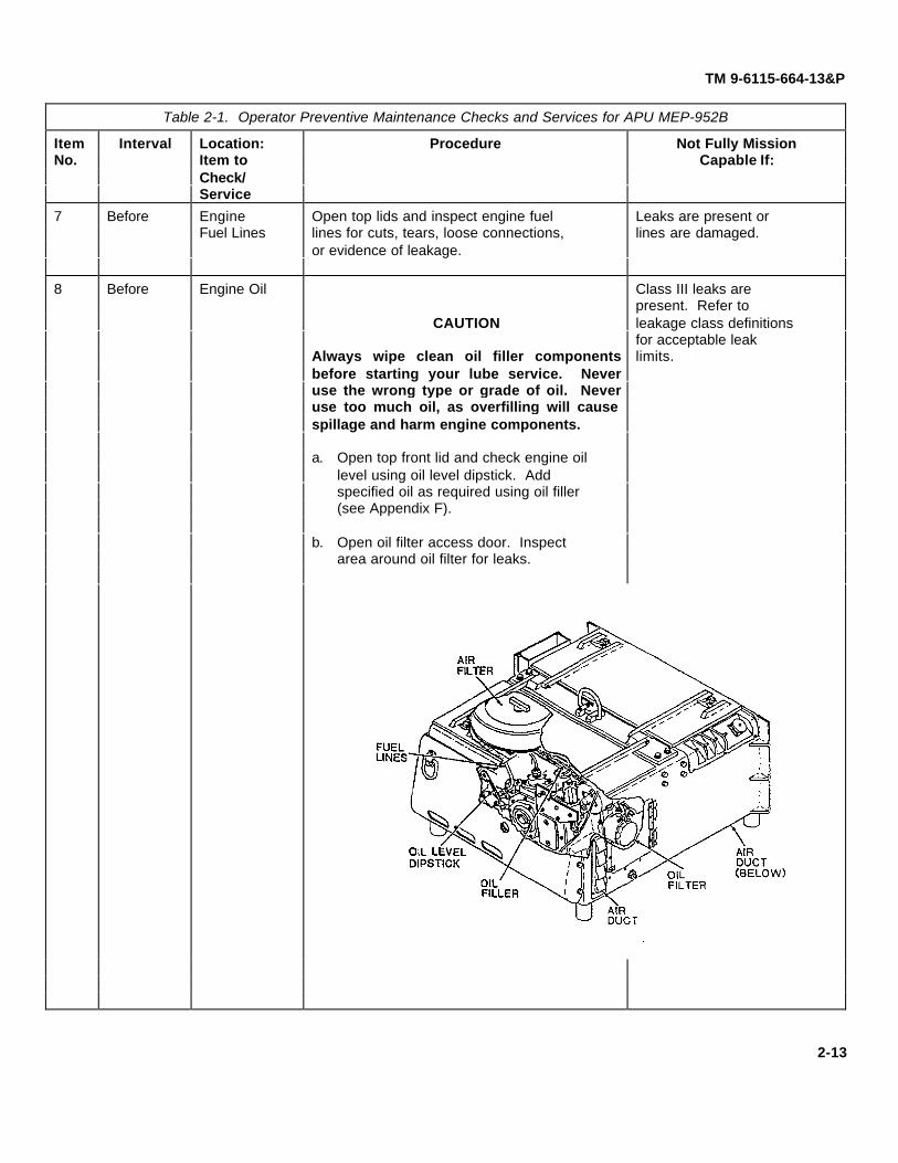
TM 9-6115-664-13&P
Table 2-1. Operator Preventive Maintenance Checks and Services for APU MEP-952B
Item Interval Location: Procedure Not Fully MissionNo. Item to Capable If:
Check/Service
7 Before Engine Open top lids and inspect engine fuel Leaks are present orFuel Lines lines for cuts, tears, loose connections, lines are damaged.
or evidence of leakage.
8 Before Engine Oil Class III leaks arepresent. Refer to
CAUTION leakage class definitionsfor acceptable leaklimits.Always wipe clean oil filler components
before starting your lube service. Neveruse the wrong type or grade of oil. Neveruse too much oil, as overfilling will causespillage and harm engine components.
a. Open top front lid and check engine oillevel using oil level dipstick. Addspecified oil as required using oil filler(see Appendix F).
b. Open oil filter access door. Inspectarea around oil filter for leaks.
2-13

TM 9-6115-664-13&P
Table 2-1. Operator Preventive Maintenance Checks and Services for APU MEP-952B
Item Interval Location: Procedure Not Fully MissionNo. Item to Capable If:
Check/Service
9 Before Engine Air a. Open top front lid and inspect engine Air filter is damaged orFilter air filter for dirt (Para. 3-7). Replace missing. Air inlet hose
filter if dirty. is damaged.
b. Inspect air inlet hose for cuts or tears.Ensure secure connection to cover.
c. Install air filter cover and connect airinlet hose to port on enclosure wall.
10 During Air Ducts Inspect air intake and exhaust ducts for Ducts are obstructed orobstructions and blockages. Clear blocked.obstructions and check ducts fordamage.
2-14

TM 9-6115-664-13&P
Table 2-1. Operator Preventive Maintenance Checks and Services for APU MEP-952B
Item Interval Location: Procedure Not Fully MissionNo. Item to Capable If:
Check/Service
11 During Engine Oil Oil level is at or belowWARNING fill level on dipstick.
(After 10 Oil is contaminated.Hours ofConstantUse)
Never service APU while engine is running.Shut down unit before servicing engine oil.Injury to personnel can occur if properprocedures are not followed.
Shut down engine. Check and serviceengine oil (refer to Table 2-1, item 8).
12 During Fuel Filter Filter separator isWater WARNING damaged or leaking.
(After 10 SeparatorHours ofConstantUse)
Never service APU while engine is running.Shut down unit before draining filterseparator. Injury to personnel can occur ifproper procedures are not followed.
Shut down engine. Drain trapped water(refer to Table 2-1, item 6).
13 After Engine Open top lids and inspect engine fuel Leaks are present orFuel Lines lines for cuts, tears, loose connections, lines are damaged.
or evidence of leakage.
14 After Overall a. Inspect for cracks, leaks, dents, Fuel leaks are present.Generator corrosion. Significant cracks existSet in enclosure or
b. Inspect for loose hardware. components.
2-15

TM 9-6115-664-13&P
Section III. OPERATION UNDER USUAL CONDITIONS
2-6. ASSEMBLY AND PREPARATION FOR USE.
WARNING
If damaged or defective components are discovered, repair must be performedbefore operation can begin. Perform required repairs and adjustments beforeproceeding. Do not operate the APU with damaged components. Personnel injurycan occur if damaged parts are left unfixed.
WARNING
Prior to placing the APU into service, operating personnel must be familiar with thelocation and function of all switches, controls, and indicators. Refer to Paragraph2-1, Operators Controls and Indicators, and Figure 2-1 before continuing with thisprocedure. Make sure that personnel are familiar with the APU before operating.Follow proper procedures. Failure to do so can result in injury to personnel anddamage to equipment.
a. Connect vehicle electrical cable to APU NATO receptacle (32, Figure 2-1). Secure using hold down strap.Ensure positive contact on both ends of cable. Inspect cable for cuts, abrasions, damaged insulation, and corrosion.Replace damaged cable before proceeding.
b. Connect vehicle fuel hose to APU fuel fitting (33). Ensure secure connection on both ends of hose. Inspecthose for cuts, cracks, deterioration, or damage. Replace damaged hose before proceeding.
c. Check and service engine oil in accordance with Appendix F, Lubrication Instructions.
2-7. INITIAL ADJUSTMENTS, DAILY CHECKS, AND SELF TEST.
a. Initial Adjustments. No initial adjustments are required for operation of the APU.
b. Daily Checks. Perform all operator PMNCS in accordance with Section II.
c. Self Test. An indicator lamp self test can be conducted when the APU remote control panel is connected.Refer to paragraph 2-8.b. There is no self test when operating from the local control panel.
2-16
TM 9-6115-664-13&P
2-8. OPERATING PROCEDURES.
WARNING
Do not operate the APU in an enclosed area unless exhaust gases are properlyvented to the outside. Exhaust fumes can be harmful if allowed to accumulate.Exhaust discharge contains noxious and deadly gases.
WARNING
Shut down the APU at first sign of failure. Continued operation can result in injuryto personnel and will cause damage to equipment. If the APU is shut down by theoperation of a safety device, do not operate again until the cause of the shut downhas been determined and eliminated.
a. Operating the APU Using Local Control Panel.
NOTE
If ambient temperature is below 32° F (0° C), refer to paragraph 2-10, Operation inUnusual Weather, for operating instructions.
(1) Place the REMOTE/ LOCAL switch (4, Figure 2-2) in the LOCAL position.
(2) Place the START / PRIME - RUN / OFF switch (1) in the PRIME - RUN position.
CAUTION
Do not hold START / PRIME - RUN / OFF switch in START position for more than 10seconds. Damage to starter motor can occur. Wait 30 seconds before placing inSTART position again. If engine does not run after third attempt, contactmaintenance personnel.
(3) Wait 5 seconds, then move the START / PRIME - RUN / OFF switch (1) to the START position. Switch isspring loaded and must be held in place. Release switch when engine starts.
CAUTION
To prevent damage, allow engine to warm up for a few minutes before activatingthe APU ON switch and applying the load. Additional warm up time may berequired in extremely cold conditions. Continually operating a cold engine canshorten its service life.
2-17

TM 9-6115-664-13&P
1. START / PRIME - RUN / OFF Switch 4. REMOTE / LOCAL Switch2. PREHEAT OIL / AIR Switch 5. REMOTE Control Panel Electrical Connector3. APU ON Switch
Figure 2-2. Operation Using Local Control Panel
(4) Momentarily move the APU ON switch (3) to the ON position, then release. The APU ON switch activates thealternator and applies the load.
b. Operating the APU Using Remote Control Panel.
NOTE
If ambient temperature is below 32° F (0º C), refer to paragraph 2-10, Operation inUnusual Weather, for operating instructions.
(1) Connect the remote control panel electrical cable to the REMOTE electrical connector (5, Figure 2-2) on thelocal control panel.
(2) Place the REMOTE / LOCAL switch (4) in the REMOTE position.
(3) Conduct remote control panel self test by pushing the PRESS TO TEST LAMPS push button (5, Figure 2-3).All LED indicator lights (3, 4, 7, 9) shall illuminate. If an indicator light fails to illuminate, refer trouble to nexthigher level of maintenance.
(4) Place the START / PRIME RUN / OFF switch (11) in the PRIME RUN position.
2-18

TM 9-6115-664-13&P
CAUTION
Do not hold START / PRIME - RUN / OFF switch in START position for more than 10seconds. Damage to starter motor can occur. Wait 30 seconds before placing inSTART position again. If engine does not run after third attempt, contactmaintenance personnel.
(5) Wait 5 seconds, then move the START / PRIME - RUN / OFF switch (I 1) to the START position. Switch isspring loaded and must be held in place. Release switch when engine starts.
CAUTION
To prevent damage, allow engine to warm up for a few minutes before activatingthe APU ON switch and applying the load. Additional warm up time may berequired in extremely cold conditions. Continually operating a cold engine canshorten its service life.
(6) Momentarily move the APU ON switch (6) to the ON position, then release. The APU ON switch activates thealternator and applies the load.
(7) Check voltmeter (1) for proper voltage. Voltmeter indicator should fall within the green band.
c. APU Shut Down. To stop the engine and shut down the APU, place the START / PRIME - RUN / OFF switch (1,Figure 2-2 or 11, Figure 2-3) in the OFF position.
d. Emergency Shutdown. In an emergency situation, press the EMERGENCY STOP push button (2, Figure 2-3) toimmediately shut down the APU. The push button must be pulled out to the off position before the APU can be startedagain. Ensure START / PRIME - RUN / OFF switch (11) is moved to OFF position.
2-9. OPERATION OF AUXILIARY EQUIPMENT.
a. Auxiliary equipment consists of the remote control panel and an auxiliary fuel hose. Refer to paragraph 2-8.b. foroperation of the remote control panel.
b. An auxiliary fuel hose is provided to allow operation of the APU using an external (to the vehicle) fuel supply.Connect the auxiliary fuel hose as follows:
(1) Disconnect vehicle fuel hose from the APU fuel fitting (33, Figure 2-1).
(2) Remove auxiliary fuel hose from underside of APU enclosure.
(3) Connect one end of auxiliary fuel hose to fuel fitting. Connect opposite end to external fuel supply. Ensureboth ends are tightened securely.
(4) Operate APU in accordance with normal procedures (paragraph 2-8).
2-19

TM 9-6115-664-13&P
1. VOLTMETER 7. APU ON Indicator2. EMERGENCY STOP Push Button 8. BATTLE SHORT Switch3. HIGH ENGINE TEMPERATURE Indicator 9. Battle Short ON Indicator4. LOW OIL PRESSURE Indicator 10. PREHEAT OIL / AIR Switch5. PRESS TO TEST LAMPS Switch 11. START / PRIME - RUN /6. APU ON Switch OFF Switch
Figure 2-3. Operation Using Remote Control Panel
2-20

TM 9-6115-664-13&P
Section IV. OPERATION UNDER UNUSUAL CONDITIONS
2-10. OPERATION IN UNUSUAL WEATHER.
a. If unit is to be operated at ambient temperature below 0° F (-18° C) for an extended period, change engine oil toMIL-L-46167, 5W-30. Refer to Appendix F for oil servicing.
b. If ambient temperature is below 32° F (0° C) , the PREHEAT OIL / AIR switch (item 2, Figure 2-2 or item 10,Figure 2-3) should be used prior to starting the engine. Perform the following procedures:
(1) The PREHEAT OIL / AIR switch is a three-position switch, spring-loaded to the off position. Moving theswitch to the OIL (up) position energizes a glow plug located in the engine oil reservoir. Moving the switchto the AIR (down) position energizes two glow plugs located in the engine intake manifold. The heaterelements (oil or air) will remain on for as long as the switch is held in the OIL or AIR position.
(2) Start the APU in accordance with paragraph 2-8.
c. When operating the APU in extremely dusty or sandy conditions, the engine air filter element and air intake ductsmust be inspected frequently to ensure that clogging or obstruction has not occurred.
2-11. EMERGENCY PROCEDURES.
WARNING
APU battle short mode is for emergency operation only. Prolonged use under thismode could damage the APU or pose potential injury hazards to personnel.
a. The APU is capable of operation with a system fault. The BATTLE SHORT switch (8, Figure 2-3) located on theremote control panel allows the APU to override anticipated system faults to continue operation.
b. To operate the APU in battle short mode, lift protective cover and place BATTLE SHORT switch (8) in the ONposition. The battle short ON indicating light (9) will illuminate to indicate battle short mode.
2-12. NUCLEAR, BIOLOGICAL, AND CHEMICAL (NBC) DECONTAMINATION PROCEDURES.
Refer to the vehicle maintenance manual, TM 9-2350-277-10, for NBC decontamination procedures.
2-21

TM 9-6115-664-13&P
2-13. HAND STARTING (MANUAL ENGINE CRANKING) PROCEDURES.
a. Before attempting to hand start, check for loose connections, broken wires, or dirty connectors. Check for properelectrolyte level in battery(s) and service as required. The hand start procedure is to be used when battery voltage is lessthan 20 VDC.
b. Open the top front lid (1, Figure 2-4) completely and allow it to rest on the rear lid.
c. Remove engine hand crank from under side of APU. Insert hand crank through opening in nose piece (3) andinto the engine's manual crank receptacle. Turn hand crank counterclockwise slightly to engage.
d. Place the REMOTE / LOCAL switch on local control panel in the LOCAL position.
e. Place the START / PRIME RUN / OFF switch in the PRIME RUN position. Fuel pump will begin operating.
f. Using your right hand, depress top of stop/hold solenoid (2) until it reaches maximum travel length and stops.Continue to hold the solenoid in the depressed position until it latches in step j.
i. Using your left hand, crank engine using hand crank until RPMs reach adequate speed to start engine.
j. The APU is now operating. Continue to hold the stop/hold solenoid (2) in the depressed position. Depress andrelease the manual start switch (4) , located on the fuel solenoid bracket.
k. Momentarily move the APU ON switch on local control panel to the ON position, then release. The APU ONswitch activates the alternator and applies the load. The APU should now be producing power and charging batteries.The stop/hold solenoid will latch in place.
I. Close top front lid (1) and secure using lid latches.
m. Replace engine hand crank onto under side of APU.
2-22

TM 9-6115-664-13&P
1. Top Front Lid2. Stop/Hold Solenoid3. Nose Piece4. Manual Start Switch
Figure 2-4. Hand Cranking
2-23/(2-24 blank)

TM 9-6115-664-13&P
CHAPTER 3OPERATOR MAINTENANCE INSTRUCTIONS
Section I LUBRICATION INSTRUCTIONS .............................................................................. 3-2
3-1 Lubrication Instructions ............................................................................................ 3-2
Section II OPERATOR TROUBLESHOOTING PROCEDURES ................................................. 3-2
3-2 General ................................................................................................................... 3-23-3 Troubleshooting....................................................................................................... 3-2
Section III OPERATOR MAINTENANCE INSTRUCTIONS ...................................................... 3-10
3-4 General ................................................................................................................. 3-103-5 Fuel Module and Fuel Hoses .................................................................................. 3-103-6 Fuel Filter Water Separator..................................................................................... 3-103-7 Engine Air Filter ....................................................................................................... 3-11
3-1

TM 9-6115-664-13&P
Section I. LUBRICATION INSTRUCTIONS
3-1. LUBRICATION INSTRUCTIONS.
Operator level lubrication instructions for the APU are contained in Appendix F of this TM. All lubricationinstructions are mandatory.
Section II. OPERATOR TROUBLESHOOTING PROCEDURES
3-2. GENERAL.
This section contains operator troubleshooting information and tests for the APU. Troubleshooting logic trees willaide in locating and correcting minor APU malfunctions. Each malfunction or trouble symptom is addressed and isfollowed by a series of inspections or tests necessary to determine the probable cause and corrective action.
3-3. TROUBLESHOOTING.
a. This chapter does not list all possible malfunctions that may occur, all tests or inspections that may be performed,or all corrective actions for each malfunction. Only those checks and tests authorized for the operator level are covered.If a malfunction is not listed, or is not remedied by corrective actions, notify personnel at a higher maintenance level.
b. If a malfunction or failure occurs during operation or performance check, perform troubleshooting in accordancewith logic tree diagrams. Refer to Table 3-1, Malfunction Index, for determining applicable troubleshooting procedure.
Table 3-1. Malfunction Index
TableMALFUNCTIONS
Engine will not crank (local control panel operation) 3-2Engine will not crank (remote control panel operation) 3-3Engine cranks but will not start 3-4Engine starts and stops 3-5Engine overheats, high temperature light (LED) illuminates 3-6Low oil pressure light (LED) illuminates 3-7APU runs but does not charge 3-8Engine emits white smoke 3-9
3-2

TM 9-6115-664-13&P
Table 3-2. ENGINE WILL NOT CRANK (LOCAL CONTROL PANEL OPERATION)
3-3

TM 9-6115-664-13&P
Table 3-3. ENGINE WILL NOT CRANK (REMOTE CONTROL PANEL OPERATION)
3-4

TM 9-6115-664-13&P
Table 3-4. ENGINE CRANKS BUT WILL NOT START
3-5

TM 9-6115-664-13&P
Table 3-5. ENGINE STARTS AND STOPS
3-6

(Para. 3-10)
TM 9-6115-664-13&P
Table 3-6. ENGINE OVERHEATS, HIGH TEMPERATURE LIGHT ILLUMINATES
Table 3-7. LOW OIL PRESSURE LIGHT ILLUMINATES
3-7

TM 9-6115-664-13&P
Table 3-8. APU RUNS BUT DOES NOT CHARGE
3-8

(Para. 3-6)
TM 9-6115-664-13&P
Table 3-9. ENGINE EMITS WHITE SMOKE
3-9

TM 9-6115-664-13&P
Section III. OPERATOR MAINTENANCE PROCEDURES
3-4. GENERAL.
This section contains information on the maintenance of the APU that is the responsibility of the operator. If aprocedure is not located in this chapter, you are not authorized to perform it.
WARNING
Never service, inspect, or perform maintenance on the APU while engine isrunning. Always shut down unit before servicing. Allow engine to cool beforehandling components. Failure to do so can result in severe bums and injuries.
3-5. FUEL MODULE AND FUEL HOSES.
a. Open top lids on APU and inspect inside of enclosure for evidence of fuel leakage. Inspect engine fuel hoses forcuts, tears, or evidence of deterioration. Check that hoses are securely fastened to fittings.
b. Slide cover latches (1, Figure 3-1) back to disengage from screws, and remove fuel module cover (2). Inspectfuel hoses for cuts, tears, or evidence of deterioration. Check that hoses are securely fastened to fittings. Inspect forsigns of leakage.
c. Inspect electrical wiring inside fuel module housing for damage. Check connectors for security of attachment.
d. If damage is found, notify unit maintenance personnel for repair.
3-6. FUEL FILTER WATER SEPARATOR.
a. Open top rear lid on APU to gain access to fuel module.
b. Slide cover latches (1, Figure 3-1) back to disengage, and remove fuel module cover (2). Inspect fuel hoses forcuts, tears, or evidence of deterioration. Check that hoses are securely fastened to fittings. Inspect for signs of leakage.
c. Inspect separator bowl (3) for trapped water. Drain water by turning drain valve (4). After water is drained, closedrain valve.
d. Fit fuel module cover (2) onto fuel module and secure using cover latches (1). Close top rear cover and secureby turning lid latches.
3-10

TM 9-6115-664-13&P
1. Cover Latch2. Fuel Module Cover3. Separator Bowl4. Drain Valve
Figure 3-1. Fuel Filter Water Separator Draining
3-7. ENGINE AIR FILTER.
a. Open top front lid on APU to gain access to engine air filter.
b. Disconnect air hose (1, Figure 3-2) from air inlet port. Disconnect hose from filter cover (3) if required byloosening clamp (2).
c. Remove air filter cover (3) from filter base (4) by unscrewing wing screw (5). Wing screw is held on cover by aretainer clip.
d. Remove air filter (6) from filter base (4) and discard. Inspect intake guard (7) for damage and replace as required.
e. Inspect air hose (1) for cuts, cracks, or tears. Replace air hose if damaged.
f. Install new air filter (6) onto filter base (4).
g. Install air filter cover (3) and secure by tightening wing screw (5).
h. Connect air hose (.) to air filter cover (3) and tighten clamp (2). Connect air hose to air inlet port.
i. Close top front lid and secure by turning lid latches.
3-11

TM 9-6115-664-13&P
1. Air Hose2. Clamp3. Air Filter Cover4. Filter Base5. Wing Screw6. Air Filter7. Intake Guard
Figure 3-2. Air Filter Replacement
3-12

TM 9-6115-664-13&P
CHAPTER 4UNIT MAINTENANCE INSTRUCTIONS
Section I LUBRICATION INSTRUCTIONS .............................................................................. 4-3
4-1 General ................................................................................................................... 4-3
Section II REPAIR PARTS; TOOLS; SPECIAL TOOLS; TEST,................................................. .4-5MEASUREMENT, AND DIAGNOSTIC EQUIPMENT (TMDE) ;AND SUPPORT EQUIPMENT
4-2 Common Tools ........................................................................................................ 4-54-3 Special Tools, TMDE, and Support Equipment........................................................... 4-54-4 Repair Parts ............................................................................................................ 4-5
Section III SERVICE UPON RECEIPT OF EQUIPMENT............................................................ 4-5
4-5 General ................................................................................................................... 4-5
Section IV PREVENTIVE MAINTENANCE CHECKS AND SERVICES (PMCS) .......................... 4-6
4-6 General ................................................................................................................... 4-64-7 PMCS Procedures ................................................................................................... 4-64-8 Cleaning Agents ...................................................................................................... 4-7
Section V UNIT TROUBLESHOOTING................................................................................... 4-11
4-9 General ................................................................................................................. 4-114-10 Troubleshooting..................................................................................................... 4-11
Section VI UNIT MAINTENANCE PROCEDURES ................................................................... 4-37
4-11 APU Case Assembly (Enclosure)............................................................................ 4-374-12 Cover Assembly .................................................................................................... 4-384-13 Oil Filter Access Door Assembly ............................................................................. 4-424-14 Valve Access Door Assembly ................................................................................ 4-444-15 Nosepiece Assembly.............................................................................................. 4-464-16 Tie Down / Hoist Ring............................................................................................. 4-484-17 External Muffler Cover............................................................................................ 4-504-18 Oil Cooler Header.................................................................................................. 4-514-19 APU Mounting Bracket ........................................................................................... 4-524-20 Local Control Panel Assembly ................................................................................ 4-534-21 Switch Assembly (Local Control Panel) ................................................................... 4-554-22 Circuit Breaker (Local Control Panel)....................................................................... 4-584-23 Remote Control Connector (Local Control Panel)..................................................... 4-604-24 Circuit Board Assembly (Local Control Panel).......................................................... 4-624-25 Voltmeter (Remote Control Panel)........................................................................... 4-64
4-1

TM 9-6115-664-13&P
Section VI UNIT MAINTENANCE PROCEDURES (continued)
4-26 Switch Assembly (Remote Control Panel)................................................................ 4-664-27 Lamp Test Switch (Remote Control Panel) .............................................................. 4-684-28 Circuit Board Assembly (Remote Control Panel) ...................................................... 4-704-29 Remote Control Cable............................................................................................ 4-724-30 Fuel Module .......................................................................................................... 4-744-31 Fuel Filter Water Separator..................................................................................... 4-784-32 Fuel Pump Assembly ............................................................................................ 4-804-33 Float Valve Housing Assembly................................................................................ 4-824-34 NATO Receptacle.................................................................................................. 4-864-35 Electrical Contractor............................................................................................... 4-884-36 Preheat Module ..................................................................................................... 4-904-37 Voltage Regulator.................................................................................................. 4-924-38 Oil Cooler Hose Assembly...................................................................................... 4-944-39 Oil Cooler Fan ....................................................................................................... 4-964-40 External Muffler...................................................................................................... 4-984-41 Internal Exhaust Assembly ................................................................................... 4-1004-42 Engine Exhaust Duct Assembly ............................................................................ 4-1024-43 Engine Air Filter ................................................................................................... 4-1044-44 Fuel Filter (In-Line)............................................................................................... 4-1064-45 Engine Start Solenoid / Manual Start Switch.......................................................... 4-1084-46 Oil Drain Assembly ............................................................................................. 4-1104-47 Valve Clearance Adjustment ................................................................................ 4-1124-48 Fuel Injector......................................................................................................... 4-1144-49 Oil Level Dipstick................................................................................................. 4-1164-50 Oil Filter ............................................................................................................. 4-1174-51 Oil Pressure Valve / Oil Cover .............................................................................. 4-1184-52 Oil Pressure Switch.............................................................................................. 4-1204-53 Oil Fill Tube ......................................................................................................... 4-1214-54 Starter................................................................................................................. 4-1234-55 Mechanical Fuel Pump......................................................................................... 4-1254-56 Air Heat Glow Plug............................................................................................... 4-1264-57 Oil Heat Glow Plug............................................................................................... 4-1274-58 Engine Temperature Switch.................................................................................. 4-1284-59 Hourmeter ........................................................................................................... 4-130
Section VII PREPARATION FOR SHIPMENT AND STORAGE............................................................... 4-132
4-60 General ............................................................................................................... 4-1324-6 Administrative Storage ......................................................................................... 4-1324-62 Short Term Storage.............................................................................................. 4-1324-63 Intermediate Term Storage ................................................................................... 4-1324-64 Shipment............................................................................................................. 4-132
4-2

TM 9-6115-664-13&P
Section I. LUBRICATION INSTRUCTIONS
4-1. GENERAL.
a. These lubrication instructions are for unit level (O) maintenance personnel. Lube intervals (on-condition or hardtime) are based on normal operation. Lube more during constant use, and less during inactive periods. Use correctgrade of lubricant for seasonal temperature expected.
CAUTION
Always wipe clean oil filler components before starting your lube service. Neveruse the wrong type or grade of oil. Never use too much oil, as overfilling willcause spillage and harm engine components.
b. The engine oil filter shall be changed when:
• It is known to be contaminated or clogged.• The prescribed hard time interval has arrived.• Engine oil is drained or changed.
c. Open oil drain valve (1, Figure 4-1) and drain engine oil. Manually crank engine three revolutions using handcrank to drain remaining oil from oil cooler and lines. Close oil drain valve.
d. Remove and replace engine oil filter (Para. 4-50).
e. Remove oil filler cap (2) and service with appropriate oil. Check level using oil level dipstick (3). Start engine andrun for two minutes. Stop engine and recheck oil level. Service as required.
f. This APU is not enrolled in the Army Oil Analysis Program (AOAP). HARDTIME INTERVALS APPLY.
g. For equipment under manufacturer's warranty, hardtime oil service intervals shall be followed. Intervals shall beshortened if lubricants are known to be contaminated or if operation is under adverse conditions (such as longer thanusual operating hours, extended idling periods, extreme dust).
Table 4-1. Lubricant Table for APU
Temperature Range Lubricant Mil. SymbolSpecification
Capacity Interval Man-hour
0 to +120° F (-18 to +49° C) MIL-L-2104, 15W-40 2.7 QTS (2.6 LTRS) 300 hours 0.25
-25 to +15° F (-32 to -9.5° C) MIL-L-46167, 5W-30 2.7 QTS (2.6 LTRS) 300 hours 0.25
4-3

TM 9-6115-664-13&P
1. Oil Drain Valve2. Oil Filler3. Oil Level Dipstick
Figure 4-1. Engine Oil Servicing
4-4

TM 9-6115-664-13&P
Section II. REPAIR PARTS; TOOLS; SPECIAL TOOLS; TEST,MEASUREMENT, AND DIAGNOSTIC EQUIPMENT (TMDE);
AND SUPPORT EQUIPMENT
4-2. COMMON TOOLS AND EQUIPMENT.
a. For authorized common tools and equipment, refer to the Modified Table of Organization and Equipment (MTOE),CTA 50-970, or CTA 8-100, as applicable to your unit.
b. Tool Kit, General Mechanics; Automotive, Supply Catalog SC5180-90-CL-N26, is the primary supply source fortools used in maintenance of the APU.
4-3. SPECIAL TOOLS, TMDE, AND SUPPORT EQUIPMENT.
Refer to Appendix G, Repair Parts and Special Tools List, for complete data on special tools and equipmentrequired for APU maintenance. Refer to the Maintenance Allocation Chart (MAC), Appendix B, for special tools andequipment used at the unit maintenance level.
4-4. REPAIR PARTS.
a. Refer to Appendix I for a list of Mandatory Replacement Parts required for unit level maintenance of the APU.
b. Repair parts are listed and illustrated in Appendix G, Repair Parts and Special Tools List.
Section III. SERVICE UPON RECEIPT
4-5. GENERAL.
Refer to paragraph 2-6 for instructions on unpacking, assembly, and servicing of APU components.
4-5

TM 9-6115-664-13&P
Section IV. UNIT PREVENTIVE MAINTENANCE CHECKSAND SERVICES (PMCS)
4-6. GENERAL.
Unit Preventive Maintenance Checks and Services (PMCS) means systematic caring, inspecting, and servicing ofequipment to keep it in good condition and to prevent breakdowns. This section lists PMCS required for the APU andauthorized for the unit maintenance level. Your mission is to ensure that the APU is ready for operation at all times. Itmust be inspected so that defects may be discovered and corrected before they result in damage or failure.
a. Be sure to perform your PMCS in the same order, so it gets to be a habit. Once you have had some practice, youwill quickly spot anything wrong.
b. Pay attention to WARNINGS, CAUTIONS, and NOTES.
c. Perform PMCS tasks at the intervals noted in Table 4-3. Do not skip PMCS intervals.
d. Use DA Form 2404 or 5988E (Equipment Inspection and Maintenance Worksheet) to record any faults youdiscover, unless you can fix them. You DO NOT need to record faults that you fix.
4-7. PMCS PROCEDURES.
a. Your Preventive Maintenance Checks and Services, Table 4-3, lists inspections and care required to keep yourAPU in good operating condition.
b. The "INTERVAL" column of Table 4-3 tells you when to do a certain check or service. Intervals are based onoperating hours, unless otherwise noted.
c. The "PROCEDURE" column of Table 4-3 tells you how to do required checks and services. Tolerances,adjustment limits, and instrument readings are included as applicable. When replacement or repair of a component isrequired, the procedures column will direct you to the appropriate task.
NOTE
Terms "ready/available" and "mission capable" refer to same status: Equipment ison hand and ready to perform its combat missions. (See DA Pam 738-750).
d. The "NOT FULLY MISSION CAPABLE IF" column in Table 4-3 tells you when your APU is nonmission capableand why the APU cannot be used.
e. If the APU does not perform as required, perform unit level troubleshooting, Section V.
f. If anything looks wrong and you can't fix it, write it on your DA Form 2404 or 5988E. IMMEDIATELY report it toyour supervisor.
4-6

TM 9-6115-664-13&P
g. When you perform PMCS you will always need a rag or two (Item 7, App. E). Following are checks that arecommon to the entire APU:
(1) Keep It Clean. Dirt, grease, oil, and debris only get in the way and may cover up a serious problem. Cleanas you work and as needed. Use dry cleaning solvent on all metal surfaces. Use soap and water whenyou clean rubber or plastic material.
(2) Rust and Corrosion. Check APU components for rust and corrosion. If any bare metal or corrosion exists,clean, and apply a thin coat of polyurethane. Report it to your supervisor.
(3) Bolts, Nuts, and Screws. Check them for obvious looseness, missing, bent, or broken condition. You can'ttry them all with a tool, but look for chipped paint, bare metal, or rust around bolt heads. If you find a bolt,nut, or screw that's loose, tighten it.
(4) Welds. Look for loose or chipped paint, rust, or gaps where parts are welded together. If you find a badweld, report it to your supervisor.
(5) Electric Wires and Connectors. Look for cracked, frayed, or broken insulation, bare wires, and loose orbroken connectors. Tighten loose connectors. Report any damaged wires to your supervisor.
(6) Hoses and Fluid Lines. Look for wear, damage, and leaks, and make sure clamps and fittings are tight.Wet spots show leaks, but a stain around a fitting or connector can also mean a leak. If a leak comes froma loose fitting or connector, tighten it. If something is broken or worn out, replace it.
4-8. CLEANING AGENTS.
WARNING
Cleaning solvents are flammable and toxic to eyes, skin, and respiratory tract.Skin and eye protections are required when working in contact with cleaningsolvents. Avoid repeated or prolonged contact. Work in well-ventilated area only.Keep away from heat, sparks, and open flame, and do not smoke while usingcleaning solvents. Failure to observe this warning can cause injury to personnel.
WARNING
USE CAUTION when using cleaning solvents. Cleaning solvents evaporate quicklyand can irritate exposed skin if solvents contact skin. in cold weather, contact ofexposed skin with cleaning solvents can cause frostbite.
4-7

TM 9-6115-664-13&P
CAUTION
When cleaning inside of enclosure, engine must be COLD (same temperature asoutside air). DO NOT point water stream directly at any electrical connection. DONOT use high pressure water supply system. Damage to engine, electrical system,and other components may result.
NOTE
Only use those authorized cleaning solvents or agents listed in Appendix E,Expendable/Durable Supplies and Materials List.
a. When using water to clean the APU enclosure, always cover all air ducts and exhaust ports using waterproofmaterial to prevent damage to components. Cover NATO receptacle, fuel fitting, and control panel assembly. Use waterpressure and volume similar to a standard household water supply.
b. After cleaning, allow APU to air dry. Do not use compressed air to dry unit. Do not run engine to decrease dryingtime.
c. Remove all waterproof material covering ducts and parts applied in step a. before starting APU.
CAUTION
Keep cleaning solvents, gasoline, and lubricants away from rubber or soft plasticparts. They will deteriorate material.
d. When cleaning grease buildup or rusty places, use cleaning solvent (Item 9, App. E) , then apply a thin coat ofpolyurethane to affected area.
4-8

TM 9-6115-664-13&P
Table 4-2. Unit Preventive Maintenance Checks and Services for Generator Set MEP-952B
ItemNo.
Interval Location:Item to
Procedure Not Fully MissionCapable If:
Check/Service
1 Quarterly Overall a. Inspect for cracks, leaks, dents, and Class m oil or any fuelGenerator corrosion. leaks are present.Set Significant cracks exist
b. Inspect for loose hardware. in enclosure or components.
2 Quarterly Local a. Inspect for security of attachment. Control or indicator isControl Check for obvious damage. damaged to the point itPanel will affect safe operation.
b. Test switches for smooth operation.Check for normal indications.
c. Perform electrical check of system usingcontrol panel test points (Table 4-4).
3 Quarterly Remote Inspect fault indicators for proper Control or indicator isControl operation using press to test button. damaged to the point itPanel will affect safe operation.
4 Quarterly Fuel a. Inspect fuel filter water separator for Leaks are present orSystem damage. Inspect for water and drain. lines are damaged. Fuel
float valve leaks.b. Inspect fuel float valve bowl for cracks
or leaks.
c. Inspect all fuel lines for cuts, tears, looseconnections, or evidence of leakage.
5 Quarterly Engine a. Inspect engine fuel piping for damage, Leaks are present orkinks, evidence of leakage. hoses are damaged.
Loose connections.b. Inspect hoses for evidence of wear,
cracking, and deterioration. Checkconnections for tightness.
4-9

TM 9-6115-664-13&P
Table 4-2. Unit Preventive Maintenance Checks and Services for Generator Set MEP-952BItem Interval Location: Procedure Not Fully MissionNo. Item to Capable If:
Check/Service
6 Quarterly Exhaust a. Inspect exhaust cover for cracks or Any type of exhaustSystem dents. Ensure secure attachment. leak is present.
b. Inspect exhaust pipe for cracks or holes.Ensure secure attachment to muffler.
c. Inspect exhaust muffler for obviousdamage. Ensure secure attachment.
7 Quarterly Electrical a. Inspect APU wiring harness for damage, Wires are damaged.System loose connections, evidence of short Receptacle pins are
circuit. damaged or missing.
b. Inspect electrical receptacles for damage,corrosion, bent, broken or missing pins.Clean deposits from receptacles.
8 300 Engine Drain and replenish engine lubricatingHours Oil oil. Refer to Lubrication Instructions
System (Para. 4-1). Remove and replace engineoil filter (Para. 4-50).
9 300 Fuel Replace fuel filter water separator filterHours Filters cartridge (Para. 4-31) and in-line fuel
filter (Para. 4-44).
10 300 Engine Inspect engine oil cooler for leaks. Class III oil leaks areHours Oil present.
Cooler
11 300 Engine Adjust engine valve clearance (Para.Hours Cylinder 4-47).
Head
12 1000 Engine Replace fuel injector (Para. 4-48).Hours Fuel
Injector
4-10

TM 9-6115-664-13&P
Section V. UNIT TROUBLESHOOTING
4-9. GENERAL.
This section contains unit level troubleshooting information and tests for the APU. Troubleshooting logic trees willhelp in locating and correcting minor APU malfunctions. Each malfunction or trouble symptom is addressed and isfollowed by a series of inspections or tests necessary to determine the probable cause and corrective action.
4-10. TROUBLESHOOTING.
a. This chapter does not list all possible malfunctions that may occur, all tests or inspections that may be performed,or all corrective actions for each malfunction. Only those checks and tests authorized for the unit level are covered. If amalfunction is not listed, or is not remedied by corrective actions, notify personnel at a higher maintenance level.
b. Prior to using troubleshooting diagrams, be sure you have performed all normal operational checks. Refer to thesystem electrical schematic (Figure FO-1) , wiring diagrams, and LED and Test Point Table (Table 4-4) for assistance introubleshooting electrical components.
c. Refer to Table 4-3, Malfunction Index, for determining applicable troubleshooting procedure.
Table 4-3. Malfunction Index
Table
ENGINE
Engine will not crank 4-5Engine will not crank, control panel circuit breaker trips continuously 4-6Engine cranks but will not start 4-7Engine will not start in cold weather 4-10Engine starts and stops 4-11Engine speed fluctuates 4-12Engine overheats 4-13Engine hammers 4-14Engine emits black smoke 4-15Engine emits white smoke 4-16
FUEL SYSTEM
Fuel system will not energize, no fuel to the APU 4-9
GENERAL SYSTEM MALFUNCTIONS
Engine operates, but no generator voltage or below rated voltage 4-8APU shutdown, low oil pressure 4-17Engine start / hold solenoid does not stay engaged 4-18
4-11

TM 9-6115-664-13&P
Table 4-4. LED and Test Point Table
LED or Test Point Location Indication
LED 1 - AIR PH Engine preheat module Illuminates when are engine air heater elementsare energized (PREHEAT OIL/AIR switch is in
AIR position).
LED 2 - OIL PH Engine preheat module Illuminates when are engine oil heater elementsare energized (PREHEAT OIL/AIR switch is in
OIL position).
LED 1 - RUN Local control panel * Illuminates when engine run signal is sent to
engine (START/RUN AND PRIME/OFF switchis in RUN position).
LED 2 - START Local control panel * Illuminates when engine is cranking (START/RUN AND PRIME/OFF switch is in START
position).
LED 3 - LOP Local control panel * Illuminates when engine oil pressure drops belowacceptable limit.
LED 4 - HT Local control panel * Illuminates when engine temperature exceedsacceptable limit.
LED 5 - APU ON Local control panel * Illuminates when APU output contractor isengaged (closed).
LED 8 - HIGH ENGINE Remote control panel Illuminates when engine temperature exceedsTEMPERATURE acceptable limit.
LED 9 - LOW OIL Remote control panel Illuminates when engine oil pressure drops belowPRESSURE acceptable limit.
LED 10 - APU ON Remote control panel Illuminates when APU output contractor isengaged (closed).
LED 11 - Battle Short ON Remote control panel Illuminates when APU is operating in battle shortconditions (BATTLESHORT switch activated).
Test Point TP 1 Local control panel * Ground / common test point.
Test Point TP 2 Local control panel * 28 VDC system test point.
Test Point TP 3 Local control panel * Alternator AC signal.
* Local control panel LEDs and test points are located on the back of the control panel, under the top rear APU cover (see Figure 2-1). Turn latches and open cover to gain access.
4-12

(Para. 4-24)
(Para. 4-54)
(Table 4-5 Sheet 1 of 4)(Table 4-5 Sheet 2 of 4)(Table 4-5 Sheet 3 of 4)(Table 4-5 Sheet 4 of 4)
TM 9-6115-664-13&P
Table 4-5. ENGINE WILL NOT CRANK (Sheet 1 of 4)
4-13

(Sheet 2)
(Para. 4-24)
TM 9-6115-664-13&P
Table 4-5. ENGINE WILL NOT CRANK (Sheet 2 of 4)
4-14

TM 9-6115-664-13&P
Table 4-5. ENGINE WILL NOT CRANK (Sheet 3 of 4)
4-15

TM 9-6115-664-13&P
Table 4-5. ENGINE WILL NOT CRANK (Sheet 4 of 4)
4-16

Para. 4-22
Para. 4-54
Para. 4-45
Para. 4-24
TM 9-6115-664-13&P
Table 4-6. ENGINE WILL NOT CRANK,CONTROL PANEL CIRCUIT BREAKER TRIPS CONTINUOUSLY
4-17

Table 4-18
Table 4-9
TM 9-6115-664-13&P
Table 4-7. ENGINE CRANKS BUT WILL NOT START
4-18

(Table 4-8 Sheet 1 of 3)(Table 4-8 Sheet 2 of 3)(Table 4-8 Sheet 3 of 3)
Para. 4-24
TM 9-6115-664-13&P
Table 4-8. ENGINE OPERATES, NO GENERATOR VOLTAGE OR BELOW RATED VOLTAGE(Sheet 1 of 3)
4-19

Para. 4-24
Para. 4-35
TM 9-6115-664-13&P
Table 4-8. ENGINE OPERATES, NO GENERATOR VOLTAGE OR BELOW RATED VOLTAGE(Sheet 2 of 3)
4-20

Para. 4-24
TM 9-6115-664-13&P
Table 4-8. ENGINE OPERATES, NO GENERATOR VOLTAGE OR BELOW RATED VOLTAGE(Sheet 3 of 3)
4-21

(Table 4-9 Sheet 1 of 2)(Table 4-9 Sheet 2 of 2) Para. 4-32
Para. 4-44
Para. 4-31
Para. 4-48
Para. 4-55
TM 9-6115-664-13&P
Table 4-9. FUEL SYSTEM WILL NOT ENERGIZE, NO FUEL TO APU (Sheet 1 of 2)
4-22

Para. 4-32
TM 9-6115-664-13&P
Table 4-9. FUEL SYSTEM WILL NOT ENERGIZE, NO FUEL TO APU (Sheet 2 of 2)
4-23

Para. 4-45
Para. 4-36
Para.4-21 or 4-26
TM 9-6115-664-13&P
Table 4-10. ENGINE WILL NOT START IN COLD WEATHER
4-24

Para. 4-52
Para. 4-31
Para. 4-44
Para. 4-24
Para. 4-24
Appendix F
(Table 4-11 Sheet 1 of 2)(Table 4-11 Sheet 2 of 2)
TM 9-6115-664-13&P
Table 4-11. ENGINE STARTS AND STOPS (Sheet 1 of 2)
4-25

Para. 4-24
Para. 4-52
TM 9-6115-664-13&P
Table 4-11. ENGINE STARTS AND STOPS (Sheet 2 of 2)
4-26

Table 4-9
Para. 4-48
Para. 4-44
Para. 4-31
Para. 4-55
Para. 4-55
Para. 4-48
TM 9-6115-664-13&P
Table 4-12. ENGINE SPEED FLUCTUATES
4-27

Para. 4-39
Para. 4-58
(Table 4-13 Sheet 1 of 2)(Table 4-13 Sheet 2 of 2)
TM 9-6115-664-13&P
Table 4-13. ENGINE OVERHEATS (Sheet 1 of 2)
4-28

Para. 4-50
Para. 4-39
TM 9-6115-664-13&P
Table 4-13. ENGINE OVERHEATS (Sheet 2 of 2)
4-29

Appendix F
Para. 4-47
TM 9-6115-664-13&P
Table 4-14. ENGINE HAMMERS
4-30

Para. 4-31
Para. 4-44
Para. 4-48
Para. 4-47
Para. 4-43
TM 9-6115-664-13&P
Table 4-15. ENGINE EMITS BLACK SMOKE
4-31

Para. 4-1
Para. 4-31
Para. 4-44
Para. 4-47
Para. 4-48
Para. 4-1
TM 9-6115-664-13&P
Table 4-16. ENGINE EMITS WHITE SMOKE
4-32

Para. 4-50
Para. 4-52
(Table 4-17 Sheet 1 of 2)(Table 4-17 Sheet 2 of 2)
TM 9-6115-664-13&P
Table 4-17. APU SHUTDOWN, LOW OIL PRESSURE (Sheet 1 of 2)
4-33

Para. 4-24
TM 9-6115-664-13&P
Table 4-17. APU SHUTDOWN, LOW OIL PRESSURE (Sheet 2 of 2)
4-34

Para. 4-45
Para. 4-24
Para. 4-45
(Table 4-18 Sheet 1 of 2)(Table 4-18 Sheet 2 of 2)
TM 9-6115-664-13&P
Table 4-18. ENGINE START / HOLD SOLENOID DOES NOT STAY ENGAGED (Sheet 1 of 2)
4-35

Para. 4-24
Para. 4-45
Para. 4-36
TM 9-6115-664-13&P
Table 4-18. ENGINE START / HOLD SOLENOID DOES NOT STAY ENGAGED (Sheet 2 of 2)
4-36

TM 9-6115-664-13&PSection VI. UNIT MAINTENANCE PROCEDURES
4-11. APU CASE ASSEMBLY (ENCLOSURE) REPAIR
This task covers inspection and repair.
INITIAL SETUP
Tools: Equipment Condition:Shop Equipment, Automotive Maintenance APU Shut Downand Repair (Item 1, App. B)
Parts/Materials:Paint (Item 6, App. E)
A. INSPECTION.
1. Inspect enclosure components for dents, cracks, warping, or other damage. Check all covers, doors, ducts, andpanels.
2. Inspect painted surfaces for chips, scratches, bare metal, roughness, or corrosion.
3. Inspect top cover and side door latches for proper operation. Latches should operate smoothly, without binding.Inspect top cover, side doors, and ducts for security of attachment. If a component is loose, tighten attaching parts asrequired.
4. Open top covers and side doors and inspect insulation material for damage. Ensure material is securely attached tocomponent. Inspect APU hoist ring and tie-down rings for security of attachment.
B. REPAIR.
WARNING
CARC paint dust is a health hazard. Wear protective eyewear, mask, and gloveswhen sanding CARC painted surfaces. Failure to comply can cause personalinjury.
1. Repair painted surfaces of enclosure by removing loose or chipped paint. Sand surfaces until smooth and remove allevidence of corrosion. Mask unpainted surfaces before painting. Paint APU using green paint (per FED-STD-595).
2. Repair stencils as required by touching up with available paint. Refer to Figure 2-3 for stencil location and verbiage.
3. Repair of parts, other than painting, is limited to removal and replacement of damaged components. Refer toapplicable paragraphs for instructions.
4-37

(Figure 4-2 Sheet 1 of 4)(Figure 4-2 Sheet 2 of 4)(Figure 4-2 Sheet 3 of 4)(Figure 4-2 Sheet 4 of 4)
TM 9-6115-664-13&P
4-12. COVER ASSEMBLY MAINTENANCE
This task covers removal, disassembly, inspection, repair, assembly, and installation
INITIAL SETUP
Tools: Personnel Required:Shop Equipment, Automotive Maintenance 2 Maintenance Personneland Repair (Item 1, App. B)
Parts/Materials: Equipment Condition:Adhesive, Loctite (Item 1, App. E) Control Panel Removed (Para. 4-20)Adhesive, Silicon (Item 2, App. E)Adhesive, Contact Spray On (Item 12, App. E)Tape, VHB (Item 8, App. E)
A. REMOVAL.
1. Lift and turn four latches (1, Figure 4-2) to unlockcovers (2, 3).
NOTE
Discard and replace all lockwashersand locknuts when removed.
2. Remove four screws (4), eight washers (5), and fourlocknuts (6) that secure cross member (7) to supportbrackets (8, 9).
WARNING
Cover assembly is heavy andawkward. Enlist help of an assistantwhen removing.
3. With the help of an assistant, lift cover assembly upand off APU enclosure.
4. Remove mounting bracket (8) from enclosure byremoving four screws (10), eight washers (11), andfour locknuts (12).
5. Remove mounting bracket (9) from enclosure byremoving four screws (13), eight washers (14), andfour locknuts (15). Figure 4-2. Cover Assembly
(Sheet 1 of 4)
4-38

TM 9-6115-664-13&P
4-12. COVER ASSEMBLY MAINTENANCE
6. Remove control panel mounting block frommounting bracket (8) only if replacement is required.
B. DISASSEMBLY.
1. Remove pawl (16, Figure 4-2) from latch shaft byremoving setscrew (17). Remove latch (18) andblock (19) from cover by removing screws (20).Remove gasket (21). Remove setscrews (22) fromblock (19) as required.
2. Remove cover (2) from cross member (7) byremoving two screws (23), eight washers (24), andtwo locknuts (25).
3. Remove insulation (26) from cross member (7) byremoving caps (28) from studs (27). Discard caps.
4. Remove hinge blocks (29) from cross member byremoving screws (30), lockwashers (31), andwashers (32).
5. Remove insulation (35, typical) from underside ofrear cover by removing four caps (33) from studs(34). Discard caps.
6. Remove insulation (35) and diagram tray fromunderside of front cover by removing eight caps (33)from studs (34).
7. Remove hinge bars (38) from covers by removingthree screws (39). Remove latch protector blocks(36) from covers by removing two screws (37).
C. INSPECTION.
1. Inspect components for dents, cracks, warping, orother damage.
2. Inspect painted surfaces for chips, scratches, baremetal, roughness, or corrosion.
3. Inspect latches for proper operation. Latches shouldoperate smoothly, free of binding.
Figure 4-2. Cover Assembly(Sheet 2 of 4)
4-39

TM 9-6115-664-13&P
4-12. COVER ASSEMBLY MAINTENANCE
4. Inspect rubber gasket (40) for cuts, permanent set,deterioration, or other damage. Check security ofattachment.
D. REPAIR.
1. Repair painted and stenciled surfaces in accordancewith Para. 4-11.
2. Remove and replace damaged gasket (40) asrequired. Cut bulk gasket to length and secureusing silicon adhesive.
3. Repair of parts, other than painting, is limited toremoval and replacement of damaged components.
E. ASSEMBLY.
1. Apply loctite adhesive to the threads of screws (37,39, Figure 4-2). Install hinge bars (38) onto coversusing three screws (39). Install protector blocks (36)using two screws (37).
2. Apply VHB tape to flanges of diagram tray andinstall onto front cover.
3. Spray contact adhesive onto back of insulation (35,typical). Secure material to underside of covers bypressing new caps (33) onto studs (34).
4. Install hinge blocks (29) to cross member (7) usingscrews (30), lockwashers (31), and washers (32).
5. Spray contact adhesive onto back of insulation (26).Secure insulation to cross member by pressing newcaps (28) onto studs (27).
6. Attach assembled covers to cross member (7) usingtwo screws (23), eight washers (24), and two nuts(25).
Figure 4-2. Cover Assembly(Sheet 3 of 4)
4-40
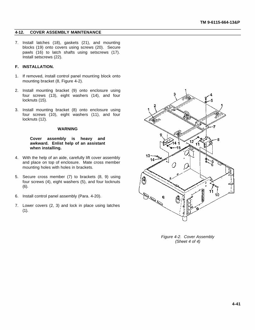
TM 9-6115-664-13&P
4-12. COVER ASSEMBLY MAINTENANCE
7. Install latches (18), gaskets (21), and mountingblocks (19) onto covers using screws (20). Securepawls (16) to latch shafts using setscrews (17).Install setscrews (22).
F. INSTALLATION.
1. If removed, install control panel mounting block ontomounting bracket (8, Figure 4-2).
2. Install mounting bracket (9) onto enclosure usingfour screws (13), eight washers (14), and fourlocknuts (15).
3. Install mounting bracket (8) onto enclosure usingfour screws (10), eight washers (11), and fourlocknuts (12).
WARNING
Cover assembly is heavy andawkward. Enlist help of an assistantwhen installing.
4. With the help of an aide, carefully lift cover assemblyand place on top of enclosure. Mate cross membermounting holes with holes in brackets.
5. Secure cross member (7) to brackets (8, 9) usingfour screws (4), eight washers (5), and four locknuts(6).
6. Install control panel assembly (Para. 4-20).
7. Lower covers (2, 3) and lock in place using latches(1).
Figure 4-2. Cover Assembly(Sheet 4 of 4)
4-41
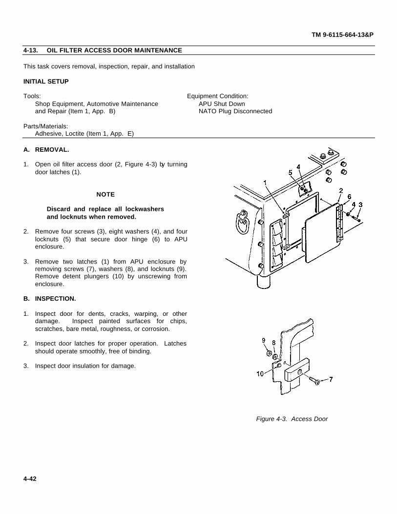
TM 9-6115-664-13&P
4-13. OIL FILTER ACCESS DOOR MAINTENANCE
This task covers removal, inspection, repair, and installation
INITIAL SETUP
Tools: Equipment Condition:Shop Equipment, Automotive Maintenance APU Shut Downand Repair (Item 1, App. B) NATO Plug Disconnected
Parts/Materials:Adhesive, Loctite (Item 1, App. E)
A. REMOVAL.
1. Open oil filter access door (2, Figure 4-3) by turningdoor latches (1).
NOTE
Discard and replace all lockwashersand locknuts when removed.
2. Remove four screws (3), eight washers (4), and fourlocknuts (5) that secure door hinge (6) to APUenclosure.
3. Remove two latches (1) from APU enclosure byremoving screws (7), washers (8), and locknuts (9).Remove detent plungers (10) by unscrewing fromenclosure.
B. INSPECTION.
1. Inspect door for dents, cracks, warping, or otherdamage. Inspect painted surfaces for chips,scratches, bare metal, roughness, or corrosion.
2. Inspect door latches for proper operation. Latchesshould operate smoothly, free of binding.
3. Inspect door insulation for damage.
Figure 4-3. Access Door
4-42

TM 9-6115-664-13&P
4-13. OIL FILTER ACCESS DOOR MAINTENANCE
4. Inspect gaskets for security of attachment, cuts, tears, deterioration, or other damage.
C. REPAIR.
1. Remove and replace damaged door gasket as required. Cut bulk gasket to length and secure by peeling off backtape to expose adhesive.
2. Repair painted and stenciled surfaces in accordance with Para. 4-11.
3. Repair of parts, other than painting, is limited to removal and replacement of damaged components.
D. INSTALLATION.
1. Install two door latches (1, Figure 4-3) onto APU enclosure using screws (7), washers (8), and locknuts (9). Screwdetent plungers (10) into enclosure.
2. Place door (2) in position on enclosure. Secure hinge (6) to enclosure surface using four screws (3), eight washers(4), and four locknuts (5).
3. Close door (2) and lock by turning door latches (1).
4. Connect NATO plug to receptacle and secure using strap.
4-43

(Figure 4-4 Sheet 1 of 2)(Figure 4-4 Sheet 2 of 2)
TM 9-6115-664-13&P
4-14. VALVE ACCESS DOOR MAINTENANCE
This task covers removal, inspection, repair, and installation
INITIAL SETUP
Tools: Equipment Condition:Shop Equipment, Automotive Maintenance APU Shut Downand Repair (Item 1, App. B) NATO Plug Disconnected
Parts/Materials:Adhesive, Loctite (item 1, App. E)Gasket, Bulk (Item 4, App. E)
A. REMOVAL.
1. Open top front cover on enclosure by turninglatches.
NOTE
Discard and replace all lockwashers andlocknuts when removed.
2. Remove screw (3, Figure 4-4), lockwasher (4), andwasher (5) and disconnect engine exhaust bellows(1) from rear of valve access door (2).
3. Open valve access door (2) by turning door latches(10).
4. Remove five screws (6), ten washers (7), and fivelocknuts (8) that secure door hinge (9) to APUenclosure.
Figure 4-4. Access Door(Sheet 1 of 2)
4-44

TM 9-6115-664-13&P
4-14. VALVE ACCESS DOOR MAINTENANCE
5. Remove two door latches (10) from APUenclosure by removing screws (11), washers (12),and locknuts (13).Remove detent plungers (14) byunscrewing from enclosure.
B. INSPECTION.
1. Inspect door for dents, cracks, warping, or otherdamage. Inspect painted surfaces for chips,scratches, bare metal, roughness, or corrosion.
2. Inspect door latches for proper operation. Latchesshould operate smoothly, free of binding.
Figure 4-4. Access Door(Sheet 2 of 2)
3. Inspect exhaust louver for obstructions, clogging, or damage. Check louver fins for damage.
4. Inspect engine exhaust bellows for damage. Make sure there are no holes or tears on bellow material. Ensuresecure connection to engine exhaust manifold.
C. REPAIR.
1. Remove and replace damaged door gasket as required. Cut bulk gasket to length and secure by peeling off tape toexpose adhesive.
2. Repair painted and stenciled surfaces in accordance with Para. 4-11.
3. Repair of parts, other than painting, is limited to removal and replacement of damaged components.
D. INSTALLATION.
1. Install two latches (10, Figure 4-4) onto APU enclosure using screws (11), washers (12), and locknuts (13). Screwin detent plungers (14).
2. Mate door (2) to enclosure. Secure hinge (9) to enclosure surface using five screws (6), ten washers (7), and fivelocknuts (8).
3. Close door (2) and lock by turning door latches (10).
4. Mate engine exhaust bellows (1) to rear of door (2). Secure using screw (3), lockwasher (4), and washer (5).
5. Close front cover and secure by locking latches.
6. Connect NATO plug to receptacle and secure using strap.
4-45

TM 9-6115-664-13&P
4-15. NOSEPIECE ASSEMBLY MAINTENANCE
This task covers removal, inspection, testing, and installation
INITIAL SETUP
Tools: Equipment Condition:Shop Equipment, Automotive Maintenance APU Shut Downand Repair (Item 1, App. B) NATO Plug Disconnected
Parts/Materials:Adhesive, Silicon (Item 2, App. E)
A. REMOVAL.
NOTE
Discard and replace all lockwashersand locknuts when removed.
1. Remove nosepiece assembly (1, Figure 4-5) frombrackets (2) by removing six screws (3),lockwashers (4), and washers (5).
2. Remove insulation from rear of nosepiece (1) byremoving caps. Discard caps.
B. INSPECTION.
1. Inspect nosepiece for dents, cracks, warping, orother damage. Inspect painted surfaces for chips,scratches, bare metal, roughness, or corrosion.
2. Inspect tie-down rings for security of attachment.If loose, tighten.
3. Inspect insulation on enclosure wall for damage.Check security of attachment.
4. Inspect lip seal on nosepiece for cuts, tears, andpermanent set. Replace as required.
Figure 4-5. Nosepiece Assembly
4-46

TM 9-6115-664-13&P
4-15. NOSEPIECE ASSEMBLY MAINTENANCE
C. REPAIR.
1. Repair painted and stenciled surfaces in accordance with Para. 4-11.
2. Repair of parts, other than painting, is limited to removal and replacement of damaged components.
D. INSTALLATION.
1. Mate insulation to rear of nosepiece assembly (1, Figure 4-5) and secure using new caps.
2. Apply a thin bead of silicon adhesive to lip at top of nosepiece (1) that mates with enclosure. Apply adhesive to top 3inches of lip on each side of nosepiece as well.
3. Mate nosepiece assembly (1) to brackets (2) and secure using six screws (3), lockwashers (4), and washers (5).
4. Connect NATO plug to receptacle and secure using strap.
4-47

(Figure 4-6 sheet 1 of 2 )(Figure 4-6 sheet 2 of 2 )
TM 9-6115-664-13&P
4-16. TIE DOWN I HOIST RING MAINTENANCE
This task covers removal, inspection, testing, and installation
INITIAL SETUP
Tools: Equipment Condition:Shop Equipment, Automotive Maintenance APU Shut Downand Repair (Item 1, App. B) NATO Plug Disconnected
Parts/Materials:Adhesive, Silicon (Item 2, App. E)
A. REMOVAL.
NOTE
Discard and replace all lockwashersand locknuts when removed.
1. Open top rear cover on enclosure by turninglatches.
2. To remove hoist ring (1, Figure 4-6), you must firstremove the APU cover assembly (Para. 412).
3. Remove hoist ring (1) and blocks (2) from coverassembly cross member by removing screws (3),washers (4), and locknuts (5). Remove rubber strip(6).
4. To remove left hand tie down ring (7), you must firstremove the local control panel (Para. 4-20).
5. Remove left hand tie down ring (7) from rear panelof enclosure (8) by removing screws (9) andlocknuts (10). Remove gasket (11).
6. To remove right hand tie down ring (7), you mustfirst remove the fuel module (Para. 4-32).
7. Remove right hand tie down ring (7) from rearpanel of enclosure (8) by removing screws (12) andlocknuts (10). Remove gasket (11).
Figure 4-6. Tie Down and Hoist Rings(Sheet 1 of 2)
4-48

TM 9-6115-664-13&P
4-16. TIE DOWN I HOIST RING MAINTENANCE
8. Remove nosepiece assembly (13) from brackets(22) by removing six screws (14), lockwashers (15),and washers (16).
9. Remove two tie down rings (17) from nosepieceassembly (13) by removing screws (18), washers(19), and locknuts (20). Remove gaskets (21).
B. INSPECTION.
Inspect hoist ring and tie down rings for cracks orother damage.
C. REPAIR.
1. Repair painted and stenciled surfaces inaccordance with Para. 4-11.
2. Repair of parts, other than painting, is limited toremoval and replacement of damaged components.
Figure 4-6. Tie Down and Hoist Rings(Sheet 2 of 2)
D. INSTALLATION.
1. Install two tie down rings (17, Figure 4-6) and gaskets (21) onto nosepiece assembly (13) using screws (18), washers (19), and locknuts (20).
2. Apply a thin bead of silicon adhesive to lip at top of nosepiece (13) that mates with enclosure. Apply adhesive to top3 inches of lip on each side of nosepiece as well.
3. Mate nosepiece assembly (13) to brackets (22) and secure using six screws (14), lockwashers (15), and washers(16).
4. Install right hand tie down ring (7) and gaskets (11) onto rear panel of enclosure (8) using screws (12) and locknuts(10).
5. Install left hand tie down ring (7), gasket (11), and control panel mounting block using screws (9) and locknuts (10).
6. Install hoist ring (1), blocks (2), and rubber strip (6) onto cover assembly cross member using screws (3), washers(4), and locknuts (5).
7. Install local control panel (Para. 4-20). Install fuel module (Para. 4-32). Install APU cover assembly (Para. 4-12).
8. Connect NATO plug to receptacle and secure using strap.
4-49

TM 9-6115-664-13&P
4-17. EXTERNAL MUFFLER COVER MAINTENANCE
This task covers removal, inspection, testing, and installation
INITIAL SETUP
Tools: Equipment Condition:Shop Equipment, Automotive Maintenance APU Shut Downand Repair (Item 1, App. B) NATO Plug Disconnected
Parts/Materials:Adhesive, Silicon (Item 2, App. E)
A. REMOVAL.
WARNING
Muffler and cover may be hot. Usecaution when handling to preventbums. Allow parts to cool beforeremoving.
NOTE
Discard and replace all lockwashersand locknuts when removed.Remove muffler cover (1, Figure 4-7)from housing (2) by removing fourscrews (3), lockwashers (4), washers(5), and spacers (6).
B. INSPECTION.
1. Inspect cover for dents, cracks, warping, or otherdamage. Inspect painted surfaces for chips,scratches, bare metal, roughness, or corrosion.
Figure 4-7. Muffler Cover
2. Inspect muffler for damage and corrosion. Replace or repair as required (Para. 4-40).
3. Inspect insulation strip (7) for damage. Ensure secure attachment. Replace as required using adhesive.
C. INSTALLATION.
1. Mate muffler cover (1, Figure 4-7) to housing (2) and secure using four screws (3), lockwashers (4), washers (5), andspacers (6).
2. Connect NATO plug to receptacle and secure using strap.
4-50

TM 9-6115-664-13&P
4-18. OIL COOLER HEADER MAINTENANCE
This task covers removal, inspection, testing, and installation
INITIAL SETUP
Tools: Equipment Condition:Shop Equipment, Automotive Maintenance APU Shut Downand Repair (Item 1, App. B) NATO PLug Disconnected
A. REMOVAL.
NOTE
Discard and replace all lockwashersand locknuts when removed.
Remove oil cooler header (1, Figure 4-8) fromenclosure side panel by removing six screws (2),lockwashers (3), and washers (4).
B. INSPECTION.
1. Inspect header for dents, cracks, warping, or otherdamage. Inspect painted surfaces for chips,scratches, bare metal, roughness, or corrosion.
2. Inspect header for clogging, obstructions, ordamage. Check fins for damage.
C. INSTALLATION.
1. Mate oil cooler header (1, Figure 4-8) to enclosureside panel. Secure using six screws (2),lockwashers (3), and washers (4).
2. Connect NATO plug to receptacle and secure
Figure 4-8. Oil Cooler Header using strap.
4-51

TM 9-6115-664-13&P
4-19. APU MOUNTING BRACKET MAINTENANCE
This task covers removal, inspection, testing, and installation
INITIAL SETUP
Tools: Equipment Condition:Shop Equipment, Automotive Maintenance APU Shut Downand Repair (Item 1, App. B) NATO Plug Disconnected
Parts/Materials:Anti-Seize Compound (Item 14, App. E
A. REMOVAL.
NOTE
Discard and replace all lockwashersand locknuts when removed.
1. Remove APU mounting bracket (1, Figure 4-9) fromleft side panel by removing bolts (2), lockwashers(3), and washers (4).
2. Remove mounting bracket (5) from right side panelby removing bolts (6), lockwashers (7), andwashers (8).
B. INSPECTION.
Inspect brackets and side panels for dents, cracks,or damage. Inspect painted surfaces for chips,scratches, bare metal, or corrosion.
C. INSTALLATION.
1. Apply anti-seize compound to bolts (2). Installmounting bracket (1) to left side panel using bolts(2), lockwashers (3), and washers (4).
2. Apply anti-seize compound to bolts (6). Installmounting bracket (5) to right side panel using bolts(6), lockwashers (7), and washers (8).
3. Connect NATO plug to receptacle and secure usingstrap.
Figure 4-9. APU Mounting Brackets
4-52
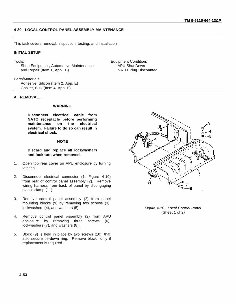
(Figure 4-10 sheet 1 of 2)(Figure 4-10 sheet 2 of 2)
TM 9-6115-664-13&P
4-20. LOCAL CONTROL PANEL ASSEMBLY MAINTENANCE
This task covers removal, inspection, testing, and installation
INITIAL SETUP
Tools: Equipment Condition:Shop Equipment, Automotive Maintenance APU Shut Downand Repair (Item 1, App. B) NATO Plug Disconnted
Parts/Materials:Adhesive, Silicon (Item 2, App. E)Gasket, Bulk (Item 4, App. E)
A. REMOVAL.
WARNING
Disconnect electrical cable fromNATO receptacle before performingmaintenance on the electricalsystem. Failure to do so can result inelectrical shock.
NOTE
Discard and replace all lockwashersand locknuts when removed.
1. Open top rear cover on APU enclosure by turninglatches.
2. Disconnect electrical connector (1, Figure 4-10)from rear of control panel assembly (2). Removewiring harness from back of panel by disengagingplastic clamp (11).
3. Remove control panel assembly (2) from panelmounting blocks (9) by removing two screws (3),lockwashers (4), and washers (5).
4. Remove control panel assembly (2) from APUenclosure by removing three screws (6),lockwashers (7), and washers (8).
5. Block (9) is held in place by two screws (10), thatalso secure tie-down ring. Remove block only ifreplacement is required.
Figure 4-10. Local Control Panel(Sheet 1 of 2)
4-53

TM 9-6115-664-13&P
4-20. LOCAL CONTROL PANEL ASSEMBLY MAINTENANCE
C. INSPECTION.
1. Inspect electrical connector on rear of control panel for corrosion and cleanliness. Ensure connector is securelyfastened.
2. Inspect electrical wiring harness for cuts, abrasions, bare wires, and evidence of short circuits. Inspect wireinsulation for damage. Ensure electrical connectors are securely attached.
3. Check control panel switches for proper operation. Inspect panel markings for legibility.
4. Inspect control panel gasket for cuts, tears, permanent set, deterioration, or other damage. Ensure gasket issecurely attached.
D. REPAIR.
1. Remove corrosion from electrical connectors.
2. Remove and replace damaged gasket. Cut new gasket to length and peel off tape to expose adhesive.
3. Repair of control panel assembly consists of removal and replacement of damaged components. Refer toappropriate paragraphs for detailed procedures.
E. INSTALLATION.
1. Mate control panel assembly (2, Figure 4-10) toAPU enclosure. Ensure sealing gasket is properlyseated. Apply silicon adhesive to threads of threescrews (6) and secure control panel assemblyusing screws, washers (7), and lock-washers (8).
2. Apply silicon adhesive to threads of two screws (3).Secure control panel assembly (2) to mountingblocks (9) using screws, washers (4), andlockwashers (5).
3. Connect electrical connector (1) to rear of controlpanel assembly (2). Secure wiring harness to backof control panel using plastic clamp (11).
4. Close top rear cover and lock by turning latches.
5. Connect NATO plug into receptacle and secureusing strap
Figure 4-10. Local Control Panel. (Sheet 2 of 2)
4-54

(Figure 4-11 Sheet 1 of 3)(Figure 4-11 Sheet 2 of 3)(Figure 4-11 Sheet 3 of 3)
TM 9-6115-664-13&P
4-21. SWITCH ASSEMBLY MAINTENANCE (LOCAL CONTROL PANEL)
This task covers removal, inspection, testing, and installation
INITIAL SETUP
Tools: Equipment Condition:Shop Equipment, Automotive Maintenance Local Control Panel Assemblyand Repair (Item 1, App. B) Removed (para. 4-20)
Parts/Materials:Adhesive, Silicon (Item 2, App. E)
A. REMOVAL.
CAUTION
Use care when separating front panelof control panel assembly fromenclosure to prevent damage toelectrical wiring.
NOTE
Discard and replace all lockwashersand locknuts when removed.
1. Remove front panel (1, Figure 4-11) from enclosure(2) by removing five screws (3), lockwashers (4),and washers (5).
2. Tag and disconnect electrical wires from rear ofswitches as required for maintenance. Figure 4-11. Switch Assembly (Sheet 1 of 3)
4-55

TM 9-6115-664-13&P
4-21. SWITCH ASSEMBLY MAINTENANCE (LOCAL CONTROL PANEL)
3. Remove START / PRIME RUN / OFF switch (9)from front panel (1) by removing attaching nut (6)and washers (7, 8).
4. Remove OIL / AIR PREHEAT switch (13) from frontpanel (1) by removing attaching nut (10) andwashers (11, 12).
5. Remove APU ON switch (17) from front panel (1)by removing attaching nut (14) and washers (15,16).
6. Remove REMOTE / LOCAL switch (21) from frontpanel (1) by removing attaching nut (18) andwashers (19, 20).
B. INSPECTION.
Inspect operator switches for corrosion or otherobvious damage. Inspect electrical connectors fordamage and evidence of electrical short.
C. TESTING.
Test suspect switches for continuity. Replace asrequired.
D. INSTALLATION.
1. Apply adhesive to threads of REMOTE / LOCALswitch (21, Figure 4-11). Install switch onto frontpanel (1) and secure using nut (18) and washers(19, 20).
2. Apply adhesive to threads of APU ON switch (17).Install switch using nut (14) and washers (15, 16).
3. Apply adhesive to threads of OIL / AIR PREHEAT
switch (13). Install switch using nut (10) andwashers (11, 12).
4. Apply adhesive to threads of START i PRIME RUN /OFF switch (9). Install switch using nut (6) and washers(7, 8).
Figure 4-11. Switch Assembly(Sheet 2 of 3)
4-56

TM 9-6115-664-13&P
4-21. SWITCH ASSEMBLY MAINTENANCE (LOCAL CONTROL PANEL)
5. Mate enclosure (2) to front panel (1). Connectelectrical wires.
6. Secure front panel (1) to enclosure (2) using fivescrews (3), lockwashers (4), and washers (5).
7. Install control panel assembly (Para. 4-20).
Figure 4-11. Switch Assembly(Sheet 3 of 3)
4-57

TM 9-6115-664-13&P
4-22. CIRCUIT BREAKER MAINTENANCE (LOCAL CONTROL PANEL)
This task covers removal, inspection, testing, and installation
INITIAL SETUP
Tools: Equipment Condition:Shop Equipment, Automotive Maintenance Local Control Panel Assemblyand Repair (Item 1, App. B) Removed (para. 4-20)
Parts/Materials:Adhesive, Silicon ( Item 2, App. E)
A. REMOVAL.
CAUTION
Use care when separating front panelof control panel assembly fromenclosure to prevent damage toelectrical wiring.
NOTE
Discard and replace all lockwashersand locknuts when removed.
1. Remove front panel (1, Figure 4-12) from enclosure(2) by removing five screws (3), lockwashers (4),and washers (5).
2. Tag and disconnect electrical wires (9) from circuitbreaker (6).
3. Remove circuit breaker (6) from enclosure (2) byremoving attaching nut (7) and washer (8).
B. INSPECTION.
1. Inspect circuit breaker for corrosion or otherobvious damage. Inspect electrical connectors fordamage and evidence of electrical short.
2. Depress circuit breaker push button to check forproper operation. Push button shall depress andreset smoothly, free of binding.
Figure 4-12. Circuit Breaker
4-58

TM 9-6115-664-13&P
4-22. CIRCUIT BREAKER MAINTENANCE (LOCAL CONTROL PANEL)
C. TESTING.
Test circuit breaker for continuity when reset button is depressed. Replace as required.
D. INSTALLATION.
1. Apply adhesive to threads of circuit breaker (6, Figure 4-12). Install circuit breaker onto rear panel (2) and secureusing attaching nut (7) and washer (8).
2. Connect electrical wires (9) to circuit breaker (6).
3. Mate enclosure (2) to front panel (1). Secure front panel to enclosure using five screws (3), lockwashers (4), andwashers (5).
4. Install control panel assembly (Para. 4-20).
4-59

TM 9-6115-664-13&P
4-23. REMOTE CONTROL CONNECTOR MAINTENANCE (LOCAL CONTROL PANEL)
This task covers removal, inspection, testing, and installation
INITIAL SETUP
Tools: Equipment Condition:Shop Equipment, Automotive Maintenance Local Control Panel Assembly
and Repair (Item 1, App. B) Removed ( para. 4-20)
Parts/Materials:Adhesive, Silicon (Item 2, App. E)
A. REMOVAL.
CAUTION
Use care when separating front panelof control panel assembly fromenclosure to prevent damage toelectrical wiring.
NOTE
Discard and replace all lockwashersand locknuts when removed.
1. Remove front panel (1, Figure 4-13) from enclosure(2) by removing five screws (3), lockwashers (4),and washers (5).
2. Tag and disconnect electrical wiring connector (11)from circuit board assembly.
3. Unscrew receptacle cap (6) from remote controlconnector (7).
4. Remove remote control connector (7) from frontpanel (1) by removing four screws (8) and locknuts(9).
B. TESTING.
Conduct continuity check of remote control connector and wiring using a multimeter.
Figure 4-13. Remote Control Connector
4-60

TM 9-6115-664-13&P
4-23. REMOTE CONTROL CONNECTOR MAINTENANCE (LOCAL CONTROL PANEL)
C. INSPECTION.
1. Inspect remote control connector for corrosion or other obvious damage. Inspect connector for damage andevidence of electrical short. Check for bent, broken or missing pins.
2. Inspect electrical wiring for cuts, abrasions, and bare wire. Inspect wire insulation for damage.
3. Inspect wiring connector (11) for bent, broken, or missing electrical contactors. Inspect circuit card connector fordamage.
D. INSTALLATION.
1. Apply silicon adhesive to rear of connector (7, Figure 4-13) where connector mates to front panel (1).
2. Install remote control connector (7) onto front panel (1) using four screws (8) and locknuts (9). Chain (10) is securedto front panel by lower right hand screw (9).
3. Install receptacle cap (6) onto remote control connector (7).
4. Mate enclosure (2) to front panel (1). Connect electrical wiring connector (11) to circuit board assembly. Secure frontpanel to enclosure using five screws (3), lockwashers (4), and washers (5).
5. Install control panel assembly (Para. 4-20).
4-61

TM 9-6115-664-13&P
4-24. CIRCUIT BOARD ASSEMBLY MAINTENANCE (LOCAL CONTROL PANEL)
This task covers removal, inspection, testing, and installation
INITIAL SETUP
Tools: Equipment Condition:Shop Equipment, Automotive Maintenance Local Control Panel Assembly
and Repair (Item 1, App. B) Removed (para. 4-20)
A. REMOVAL.
CAUTION
Use care when separating front panelof control panel assembly fromenclosure to prevent damage toelectrical wiring.
CAUTION |
Wear an anti-static bracelet whenhandling circuit board to preventdamage to components.
NOTE
Discard and replace all lockwashersand locknuts when removed.
1. Remove front panel (1, Figure 4-14) from enclosure(2) by removing five screws (3), lockwashers (4),and washers (5). Use care when separating toprevent damage to electrical wiring.
2. Tag and disconnect four electrical wiringconnectors (7, 8, 9, 10) from circuit board assembly(11). Remove jumper (6).
3. Remove circuit card board (11) from enclosure (2)by removing six screws (12).
Figure 4-14. Circuit Board Assembly
4-62

TM 9-6115-664-13&P
4-24. CIRCUIT CARD ASSEMBLY MAINTENANCE (LOCAL CONTROL PANEL)
B. INSPECTION.
1. Inspect electrical wiring for cuts, abrasions, and bare wire. Inspect wire insulation for damage.
2. Inspect wiring connectors for bent, broken, or missing electrical contactors.
3. Inspect LED indicator lights and circuit board test points for obvious damage. Ensure all are securely fastened to theboard. Inspect LEDs for cracks.
C. INSTALLATION.
CAUTION
Wear an anti-static bracelet when handling circuit board to prevent damage tocomponents.
1. Install circuit board assembly (11, Figure 4-14) onto enclosure (2) using six screws (12).
2. Plug jumper (6) and four electrical wiring connectors (7, 8, 9, 10) into circuit board assembly (11).
3. Mate enclosure (2) to front panel (1). Secure front panel to enclosure using five screws (3), lockwashers (4), andwashers (5).
4. Install control panel assembly (Para. 4-20).
4-63

TM 9-6115-664-13&P
4-25. VOLTMETER MAINTENANCE (REMOTE CONTROL PANEL)
This task covers removal, inspection, testing, and installation
INITIAL SETUP
Tools: Equipment Condition:Shop Equipment, Automotive Maintenance Remote Cable Disconnected From
and Repair (Item 1, App. B) Local Control Panel Assembly
A. REMOVAL.
CAUTION
Use care when separating remotecontrol front panel from housing toprevent damage to electrical wiring.
NOTE
Discard and replace all Iockwashersand locknuts when removed.
1. Remove front panel (1, Figure 4-15) from remotehousing (2) by removing six screws (3),lockwashers (4), and washers (5).
2. Disconnect remote cable electrical connector (6)from circuit board assembly.
3. Tag and disconnect electrical wires from rear ofvoltmeter (7).
4. Remove voltmeter (7) from front panel (1) byremoving attaching nuts (8) and bracket (9).
B. INSPECTION.
1. Inspect meter for broken glass and damage to frontpanel. Inspect electrical connectors for corrosion,damage, and evidence of electrical short.
2. Inspect electrical wiring for cuts, abrasions, andbare wire. Inspect wire insulation for
Figure 4-15. Voltmeter damage.
4-64
TM 9-6115-664-13&P
4-25. VOLTMETER MAINTENANCE (REMOTE CONTROL PANEL)
C. INSTALLATION.
1. Install voltmeter (7, Figure 4-15) onto front panel (1) using nuts (8) and bracket (9).
2. Connect electrical wires to rear of voltmeter (7) and secure using connector nuts.
3. Connect remote cable electrical connector (6) to circuit board assembly.
4. Mate front panel (1) to remote housing (2) and secure using six screws (3), lockwashers (4), and washers (5).
4-65

TM 9-6115-664-13&P
4-26. SWITCH ASSEMBLY MAINTENANCE (REMOTE CONTROL PANEL)
This task covers removal, inspection, testing, and installation
INITIAL SETUP
Tools: Equipment Condition:Shop Equipment, Automotive Maint enance Remote Cable Disconnected Fromand Repair (Item 1, App. B) Local Control Panel Assembly
A. REMOVAL.
CAUTION
Use care when separating remotecontrol front panel from housing toprevent damage to electrical wiring.
NOTE
Discard and replace all lockwashersand locknuts when removed.
1. Remove front panel (1, Figure 4-16) from remotehousing (2) by removing six screws (3),lockwashers (4), and washers (5).
2. Disconnect remote cable electrical connector (6)from circuit board assembly. Tag and disconnectelectrical wires from switches as required formaintenance.
3. Remove START / PRIME RUN / OFF switch (7)from front panel (1) by removing attaching nut (8)and washer (9).
4. Remove OIL / AIR PREHEAT switch (10) fromfront panel (1) by removing attaching nut (11) andwasher (12).
5. Remove BATTLE SHORT switch (13) from frontpanel (1) by removing attaching nut (14). Removeswitch guard (15).
Figure 4-16. Switch Assembly
4-66

TM 9-6115-664-13&P
4-26. SWITCH ASSEMBLY MAINTENANCE (REMOTE CONTROL PANEL)
6. Remove APU ON switch (16) from front panel (1) by removing attaching nut (17) and washer (18).
7. Unscrew button (20) from EMERGENCY STOP switch shaft. Remove switch (19) from front panel (1) by removingattaching nut (21).
B. INSPECTION.
1. Inspect operator switches for corrosion or other obvious damage. Inspect electrical connectors for corrosion,damage, and evidence of electrical short.
2. Inspect electrical wiring for cuts, abrasions, and bare wire. Inspect wire insulation for damage.
3. Inspect silicon edge seal for cuts, deterioration, or other damage. Check security of attachment. Replace asrequired.
C. TESTING.
Test suspect switches for continuity. Replace as required.
D. INSTALLATION.
1. Install START / PRIME RUN / OFF switch (7, Figure 4-16) onto front panel (1) using nut (8) and washer (9).
2. Install OIL / AIR PREHEAT switch (10) onto front panel (1) using nut (11) and washer (12).
3. Install BATTLE SHORT switch (13) and switch guard (15) onto front panel (1) using nut (14).
4. Install APU ON switch (16) onto front panel (1) using nut (17) and washer (18).
5. Install EMERGENCY STOP switch (19) onto front panel (1) using nut (21). Screw button (20) onto switch shaft.
6. Connect remote cable electrical connector (6) to circuit card assembly.
7. Mate front panel (1) to remote housing (2) and secure using six screws (3), lockwashers (4), and washers (5).
4-67

TM 9-6115-664-13&P
4-27. LAMP TEST SWITCH MAINTENANCE (REMOTE CONTROL PANEL)
This task covers removal, inspection, testing, and instillation
INITIAL SETUP
Tools: Equipment Condition:Shop Equipment, Automotive Maintenance Remote Cable Disconnected Fromand Repair (Item 1, App. B) Local Control Panel Assembly
A. REMOVAL.
CAUTIONUse care when separating remotecontrol front panel from housing toprevent damage to electrical wiring.
NOTEDiscard and replace all lockwashersand locknuts when removed.
1. Remove front panel (1, Figure 4-17) from remotehousing (2) by removing six screws (3),lockwashers (4), and washers (5).
2. Tag and disconnect remote cable electricalconnector (6) from circuit board assembly.
3. Before disconnecting electrical wires from lamp testswitch (7), test switch in accordance with paragraphC.
4. Disconnect electrical wires from rear of lamp testswitch (7).
5. Remove lamp test switch (7) from front panel (I) byremoving attaching nut (8).
B. INSPECTION.
1. Inspect lamp test switch for corrosion or otherobvious damage. Inspect electrical connectors forcorrosion, damage, and evidence of electrical short.
Figure 4-17. Lamp Test Switch
4-68

TM 9-6115-664-13&P
4-27. LAMP TEST SWITCH MAINTENANCE (REMOTE CONTROL PANEL)
2. Inspect electrical wiring for cuts, abrasions, and bare wire. Inspect wire insulation for damage.
C. TESTING.
1. Carefully peel back shrink-wrap to expose terminals on rear of lamp test switch (7).
2. Press switch and check for continuity between terminals. Replace as required.
D. INSTALLATION.
1. Install lamp test switch (7, Figure 4-17) onto front panel (1) using attaching nut (8).
2. Solder electrical wires to rear of lamp test switch (7).
3. Connect remote cable electrical connector (6) to circuit board assembly.
4. Mate front panel (1) to remote housing (2) and secure using six screws (3), lockwashers (4), and washers (5).
4-69

TM 9-6115-664-13&P
4-28. CIRCUIT BOARD ASSEMBLY MAINTENANCE (REMOTE CONTROL PANEL)
This task covers removal, inspection, and instillation
INITIAL SETUP
Tools: Equipment Condition:Shop Equipment, Automotive Maintenance Remote Cable Disconnected Fromand Repair (Item 1, App. B) Local Control Panel Assembly
A. REMOVAL.
CAUTION
Use care when separating remotecontrol front panel from housing toprevent damage to electrical wiring.
CAUTION
Wear an anti-static bracelet whenhandling circuit board to preventdamage to components.
NOTE
Discard and replace all lockwashersand locknuts when removed.
1. Remove front panel (1, Figure 4-18) from remotehousing (2) by removing six screws (3),lockwashers (4), and washers (5).
2. Disconnect remote cable electrical connector (6)from circuit board assembly.
3. Disconnect electrical connector (7) from circuitboard assembly (8). Remove circuit card assemblyfrom front panel (1) by removing five screws (9).
Figure 4-18. Circuit Board Assembly
4-70

TM 9-6115-664-13&P
4-28. CIRCUIT BOARD ASSEMBLY MAINTENANCE (REMOTE CONTROL PANEL)
B. INSPECTION.
1. Inspect circuit board assembly for obvious damage. Inspect electrical connectors for corrosion, damage, andevidence of electrical short. Check for bent, broken, or missing pins.
2. Inspect electrical wiring for cuts, abrasions, and bare wire. Inspect wire insulation for damage.
3. Inspect wiring connectors for bent, broken, or missing electrical contactors.
4. Inspect LED indicator lights for obvious damage. Ensure LEDs are securely fastened to circuit board.
C. INSTALLATION.
CAUTION
Wear an anti-static bracelet when handling circuit board to prevent damage to components.
CAUTION
Ensure circuit card LEDs are aligned with front panel mounting holes to prevent damage to LEDs.
1. Attach circuit board assembly (8, Figure 4-18) to front panel (1) using fi ve screws (9).
2. Connect electrical connector (7) to circuit board assembly (8).
3. Connect remote cable electrical connector (6) to circuit board assembly.
4. Mate front panel (1) to remote housing (2) and secure using six screws (3), lockwashers (4), and washers (5).
4-71

TM 9-6115-664-13&P
4-29. REMOTE CONTROL CABLE MAINTENANCE
This task covers removal, testing, inspection, and instillation
INITIAL SETUP
Tools: Equipment Condition:Shop Equipment, Automotive Maintenance Remote Cable Disconnected Fromand Repair (Item 1, App. B) Local Control Panel Assembly
A. REMOVAL.
CAUTION
Use care when separating remotecontrol front panel from housing toprevent damage to electrical wiring.
NOTE
Discard and replace all lockwashersand locknuts when removed.
1. Remove front panel (1, Figure 4-19) from remotehousing (2) by removing six screws (3),lockwashers (4), and washers (5).
2. Disconnect remote cable electrical connector (6)from circuit board assembly.
3. Disconnect remote receptacle (7) from electricalplug (8).
4. Remove electrical plug (8) from remote housing (2)by removing four screws (9) and locknuts (10).Feed electrical connector and wire through hole inbottom of housing.
5. Remove vehicle mounting plate (11) from remotehousing (2) by removing four locknuts (12), screws(13), and washers (14, 15). Separate halves ofrubber isolators (16).
Figure 4-19. Remote Control Cable
4-72

TM 9-6115-664-13&P
4-29. REMOTE CONTROL CABLE MAINTENANCE
B. TESTING.
Conduct continuity check of remote control cable using a digital multimeter.
C. INSPECTION.
1 Inspect remote cable electrical connector for damage. Inspect connector for corrosion, damage, and evidence ofelectrical short. Check for bent, broken, or missing pins.
2. Inspect electrical wiring for cuts, abrasions, and bare wire. Inspect wire insulation for damage.
3. Inspect wiring connectors for bent, broken, or missing electrical contacts.
D. INSTALLATION.
1. Install halves of four rubber isolators (16, Figure 4-19) onto remote housing (2). Mate vehicle mounting plate (11) tohousing and secure using four screws (13), washers (14, 15), and locknuts (12)
2. Feed electrical connector and wiring through hole in bottom of remote housing (2). Mate flanged plug (6) to housingand secure using four screws (9) and locknuts (10).
3. Connect remote receptacle (7) to plug (8).
4. Connect remote cable electrical connector (6) to circuit board assembly.
5. Mate front panel (1) to remote housing (2) and secure using six screws (3), lockwashers (4), and washers (5).
4-73

(Figure 4-20 sheet 1 of 4)(Figure 4-20 sheet 2 of 4)(Figure 4-20 sheet 3 of 4)(Figure 4-20 sheet 4 of 4)
TM 9-6115-664-13&P
4-30. FUEL MODULE MAINTENANCE
This task covers removal, inspection, repair, and installation
INITIAL SETUP
Tools: Equipment Condition:Shop Equipment, Automotive Maintenance APU Shut Downand Repair (Item 1, App. B)
A. REMOVAL
WARNING
Disconnect electrical cable fromNATO receptacle before performingany maintenance on the fuel module.Failure to do so can result inelectrical shock.
NOTE
Discard and replace all lockwashersand locknuts when removed.
1. Disconnect NATO plug from fuel modulereceptacle. Disconnect vehicle fuel supply hosefrom fuel fitting.
2. Open top rear cover on enclosure by turninglatches.
3. Slide fuel module cover latches (3, Figure 4-20)back to disengage, and remove fuel module cover(1) from fuel module enclosure (2).
4. Remove cover latches (3) and locking screws onlyif replacement is required.
Figure 4-20. Fuel Module (Sheet 1 of 4)
4-74

TM 9-6115-664-13&P
4-30. FUEL MODULE MAINTENANCE
5. Disconnect electrical wiring connector (4) fromelectrical receptacle (5).
6. Tag and disconnect electrical cables (6) from feed-thru studs (7) by removing stud nuts and washers.
7. Tag and disconnect fuel supply line (8) from fitting(9). Tag and disconnect fuel return line (10) fromfitting (11).
8. Remove plate (12) by removing screws (13),lockwashers (14), and washers (15).
9. Remove latch block (18) by removing screws (17).
10. Remove fuel module enclosure (2) from inside ofAPU enclosure by removing six bolts (18),lockwashers (19), and washers (20). Place fuelmodule on a clean work surface for furthermaintenance.
B. INSPECTION.
1. Inspect fuel module components for signs of leakageand damage. Check security of all electrical andfluid connections.
2. Inspect fuel hoses for cuts, cracks, or deterioration.Check for security of attachment to fittings.
3. Inspect electrical wiring for cuts, abrasions, and barewire. Check wiring insulation for damage.
4. Inspect feed-thru studs for corrosion or otherobvious damage. Check for evidence of electricalshort.
5. Inspect fuel module cover and enclosure for dents,cracks, corrosion, or deformation.
Figure 4-20. Fuel Module(Sheet 2 of 4)
4-75

TM 9-6115-664-13&P
4-30. FUEL MODULE MAINTENANCE
C. REPAIR.
Repair of the fuel module assembly is limited toremoval and replacement of defective components.Refer to applicable task for component removal andreplacement procedures.
D. INSTALLATION.
1. Mate fuel module enclosure (2, Figure 4-20) to APUenclosure and secure using six bolts (18),lockwashers (19), and washers (20).
2. Install plate clip (12) using two screws (13),lockwashers (14), and washers (15).
3. Install latch block (18) using screws (17).
4. Connect fuel supply line (8) to fitting (9).Connect fuel return line (10) to fitting (11).
5. Connect electrical cables (6) to feed-thru studs (7)using stud nuts and washers.
6. Connect electrical wiring connector (4) to electricalreceptacle (5).
Figure 4-20. Fuel Module(Sheet 3 of 4)
4-76

TM 9-6115-664-13&P
4-30. FUEL MODULE MAINTENANCE
7. If removed, install cover latches (3) and lockingscrews.
8. Mate fuel module cover (1) to enclosure (2).Lock in place by engaging cover latches (3).
9. Close top rear cover and lock using latches.
10. Connect vehicle fuel supply hose to fuel fitting.Connect NATO plug to receptacle.
Figure 4-20. Fuel Module(Sheet 4 of 4)
4-77

TM 9-6115-664-13&P
4-31. FUEL FILTER WATER SEPARATOR MAINTENANCE
This task covers inspection and repair.
INITIAL SETUP
Tools: Equipment Condition:Shop Equipment, Automotive Maintenance Fuel Module Removed (Para. 4-30)and Repair (Item 1, App. B)
Parts/Materials:Sealant, Thread (Item 4, App. E)
A. REMOVAL
NOTE
Discard and replace all lockwashersand locknuts when removed.
1. Slide fuel module cover latches (3, Figure 4-21)back to disengage, and remove fuel module cover(1) from fuel module enclosure (2).
2. Remove cover latches (3) and locking screws only ifreplacement is required.
3. Open drain valve (4) and drain trapped waterthrough hose (5). Close drain valve and disconnecthose.
4. Unscrew filter ring (6) from filter header (7).
5. Remove filter element (8) from filter header (7).Discard element.
6. Tag fuel hoses (9). Disconnect fuel hoses fromelbows (10, 11). Remove elbows from fuel filterheader (7).
7. Remove filter header (7) from fuel module byremoving screws (12), washers (13), and locknuts(14).
Figure 4-21. Filter Water Separator
4-78
TM 9-6115-664-13&P
4-31. FUEL FILTER WATER SEPARATOR MAINTENANCE
B. INSPECTION.
1. Inspect fuel filter water separator for signs of leakage and damage. Inspect for cracks, dents, scratches, andsigns of corrosion.
2. Inspect fuel hoses for punctures, cuts, cracks, or deterioration.
3. Inspect all fuel fittings for damage and deformation. Inspect for stripped, crossed, or damaged threads.
C. INSTALLATION.
1. Apply thread sealant to threads of elbows (10, 11, Figure 4-21) that install into fuel filter header (7). Installelbows (see figure for orientation).
2. Mate filter header (7) to fuel module and secure using screws (12), washers (13), and locknuts (14).
3. Connect drain hose (5) to drain valve (4). Ensure drain valve is closed.
4. Connect fuel hoses (9) to elbows (10, 11).
5. Screw new filter element (8) into header (7). Tighten bolt (8) to secure element. Install filter ring (6).
6. Mate fuel module cover (I) to enclosure housing (2). Lock in place by engaging cover latches (3).
7. Install fuel module (Para. 4-30).
4-79
TM 9-6115-664-13&P
4-32. FUEL PUMP ASSEMBLY MAINTENANCE
This task covers inspection and repair.
INITIAL SETUP
Tools: Equipment Condition:Shop Equipment, Automotive Maintenance Fuel Module Removed (Para. 4-30)and Repair (Item 1, App. B)
Parts/Materials:Sealant, Thread (Item 4, App. E)
A. REMOVAL
NOTE
Discard and replace all lockwashers and locknuts when removed.
1. Remove fuel module front plate (1, Figure 4-22) from enclosure (2) by removing four screws (3), lockwashers (4),washers (5), and two screws (6).
2. Place a container near the module to capture fluid during disassembly. Tag and disconnect two fuel hoses (10) fromrear of bulkhead fittings (7).
3. Disengage electrical connector (8) from front plate (1).
4. Tag and disconnect electrical cables from rear of feed-thru studs (9) by removing stud nuts and washers.
5. Disconnect fuel hose (21) from fuel water separator (11).
6. Disconnect fuel hose (14) from fitting (15). Remove fitting from fuel pump (12).
7. Tag and disconnect electrical wires (13).
8. Remove fuel pump (12) from bottom of fuel module by removing nuts (16) and washers (17, 18, 19) from studs (20).Remove rubber strip (22) only if replacement is required.
9. Disconnect fuel hose (21) from fuel pump (12).
B. INSPECTION.
1. Inspect fuel pump for signs of leakage and damage. Inspect for cracks, dents, scratches, and signs of corrosion.
2. Inspect fuel hoses for punctures, cuts, cracks, or deterioration.
4-80

TM 9-6115-664-13&P
4-32. FUEL PUMP ASSEMBLY MAINTENANCE
3. Inspect all fuel fittings for damage and deformation.Inspect for stripped, crossed, or damaged threads.
4. Inspect electrical wiring for cuts, abrasions, or barewire. Inspect wire insulation for damage.
C. INSTALLATION.
1. Apply thread sealant to threads of elbow on hose(21, Figure 4-22). Install hose into fuel pump (12).Refer to figure for orientation of elbow.
2. Apply thread sealant to threads of fitting (15) thatinstall into fuel pump (12). Install fitting into pump.
3. Install fuel pump (12) onto studs (20) using nuts (16)and washers (17, 18, 19).
4. Connect electrical wires (13).
5. Connect fuel hose (14) to fitting (15).
6. Install fuel module front plate (1) onto enclosure (2)using four screws (3), lockwashers (4), washers (5),and two screws (6).
7. Connect two fuel hoses (10) to rear of bulkheadfittings (7).
8. Connect electrical cables to rear of feed-thru studs(9) and secure using stud nuts and washers. Installelectrical connector (8) into hole in front panel.
9. Install fuel module assembly (Para. 4-30).
Figure 4-22. Fuel Pump Assembly
4-81

(Figure 4-23 Sheet 1 of 4)(Figure 4-23 Sheet 2 of 4)(Figure 4-23 Sheet 3 of 4)(Figure 4-23 Sheet 4 of 4)
TM 9-6115-664-13&P
4-33. FLOAT VALVE HOUSING ASSEMBLY MAINTENANCE
This task covers inspection and repair.
INITIAL SETUP
Tools: Equipment Condition:Shop Equipment, Automotive Maintenance Fuel Module Removed (Para. 4-30)and Repair (Item 1, App. B)
Parts/Materials:Sealant, Thread (Item 4, App. E)
A. REMOVAL
NOTE
Discard and replace all lockwashersand locknuts when removed.
1. Remove fuel module front plate (1, Figure 423) fromenclosure (2) by removing four screws (3),lockwashers (4), washers (5), and two screws (6).
2. Tag and disconnect two fuel hoses (10) from rear ofbulkhead fittings (7).
3. Disengage electrical connector (8) from front plate(1).
4. Tag and disconnect electrical cables from rear offeed-thru studs (9) by removing stud nuts andwashers.
5. Disconnect fuel hose (14) from fuel pump.
6. Remove float valve housing assembly (13) fromenclosure (2) by removing screws (36), locknuts(21), and washers (22).
7. Disconnect fuel hose (13) and elbow (11) fromhousing assembly (37). Remove hose clip (12) onlyif replacement is required.
Figure 4-23. Float Valve Housing (Sheet 1 of 4)
4-82

TM 9-6115-664-13&P
4-33. FLOAT VALVE HOUSING ASSEMBLY MAINTENANCE
8. Disconnect fuel hose (14) and elbow (15) fromhousing assembly (37). Remove hose clip (16) onlyif replacement is required.
9. Disconnect fuel hose (17), elbow (18), and adapter(20) from housing assembly (37). Remove hose clip(19) only if replacement is required.
B. DISASSEMBLY.
1. Remove cover (23, Figure 4-23) from housing (24)by removing screws (25) and washers (26).Remove cover gasket (27).
2. Detach float (28) from shutoff valve (29) by removingpin (30). Carefully remove float from housing (24).
3. Remove shutoff valve (29) from housing (24) byremoving nut (31). Inspect O-ring (32) for damage.Remove and discard if damaged.
4. Remove vent (33) from housing (24). Remove plugs(34, 35) only as required.
C. INSPECTION.
1. Inspect cover gasket for cuts, tears, deterioration,or signs of permanent set. Replace gasket if anydamage is suspected.
2. Inspect float for damage. Inspect for cracks, dents,scratches, and signs of corrosion.
3. Inspect shutoff valve for damage and signs ofcorrosion. Check that valve orifice is clear and freefrom contaminant build-up. Ensure valve flap opensfreely, free of binding or sticking.
4. Inspect cover and housing for cracks, dents,scratches, and signs of leakage. Inspect housingports for damage
Figure 4-23. Float Valve Housing.(Sheet 2 of 4)
4-83

TM 9-6115-664-13&P
4-33. FLOAT VALVE HOUSING ASSEMBLY MAINTENANCE
5. Inspect fuel hoses for punctures, cuts, cracks, ordeterioration.
6. Inspect all fuel fittings for damage and deformation.Inspect for stripped, crossed, or damaged threads.
D. REPAIR.
Repair of the float valve housing assembly is limitedto removal and replacement of damagedcomponents.
E. ASSEMBLY.
1. Install thread sealant to threads of vent (33, Figure4-23) and plugs (34, 35). Install vent and plugs intohousing (24).
2. Mate shutoff valve (29) to housing (24), ensuringproper orientation of float hinge. Secure valve tohousing using nut (31).
3. Install float (28) into housing (24) and attach toshutoff valve (29) using pin (30). Move float withfingers to ensure operation is smooth and free ofbinding.
4. Mate cover gasket (27) to housing (24), ensuringproper hole alignment. Install cover (23) usingscrews (25) and washers (26).
Figure 4-23. Float Valve Housing(Sheet 3 of 4)
4-84
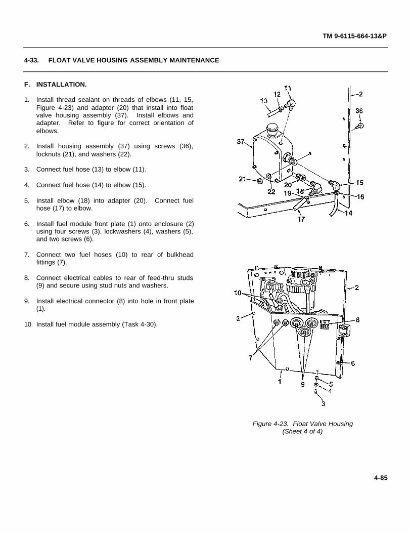
TM 9-6115-664-13&P
4-33. FLOAT VALVE HOUSING ASSEMBLY MAINTENANCE
F. INSTALLATION.
1. Install thread sealant on threads of elbows (11, 15,Figure 4-23) and adapter (20) that install into floatvalve housing assembly (37). Install elbows andadapter. Refer to figure for correct orientation ofelbows.
2. Install housing assembly (37) using screws (36),locknuts (21), and washers (22).
3. Connect fuel hose (13) to elbow (11).
4. Connect fuel hose (14) to elbow (15).
5. Install elbow (18) into adapter (20). Connect fuelhose (17) to elbow.
6. Install fuel module front plate (1) onto enclosure (2)using four screws (3), lockwashers (4), washers (5),and two screws (6).
7. Connect two fuel hoses (10) to rear of bulkheadfittings (7).
8. Connect electrical cables to rear of feed-thru studs(9) and secure using stud nuts and washers.
9. Install electrical connector (8) into hole in front plate(1).
10. Install fuel module assembly (Task 4-30).
Figure 4-23. Float Valve Housing(Sheet 4 of 4)
4-85

TM 9-6115-664-13&P
4-34. NATO RECEPTACLE MAINTENANCE
This task covers inspection and repair.
INITIAL SETUP
Tools: Equipment Condition:Shop Equipment, Automotive Maintenance APU Shut Downand Repair (Item 1, App. B) NATO Plug Disconnected
A. REMOVAL
WARNING
Disconnect electrical cable fromNATO receptacle before performingany maintenance on the fuel module.Failure to do so can result inelectrical shock.
NOTE
Discard and replace all lockwashersand locknuts when removed.
1. Disconnect NATO plug from fuel module receptacle.Disconnect vehicle fuel supply hose from quickdisconnect fitting.
2. Open top rear cover on enclosure by turning latches.
3. Slide fuel module cover latches (3, Figure 4-24)back to disengage, and remove fuel module cover(1) from enclosure (2).
4. Remove cover latches (3) and locking screws only ifreplacement is required.
5. Tag negative electrical wire (4). Disconnect wirefrom NATO receptacle (5) by removing bolt (6) andlockwasher (7).
6. Tag positive electrical wires (8, 9). Disconnectwires from NATO receptacle (5) by removing bolt(10) and lockwasher (11).
Figure 4-24. NATO Receptacle
4-86

TM 9-6115-664-13&P
4-34. NATO RECEPTACLE MAINTENANCE
7. Tag ground electrical lug (12). Remove NATO receptacle (5) from fuel module by removing screws (13) and nuts(14). Remove gasket (15).
B. INSPECTION.
1. Inspect electrical wiring for cuts, abrasions, and bare wire. Check wiring insulation for damage.
2. Inspect NATO receptacle for corrosion or other obvious damage. Check for evidence of electrical short.
3. Inspect NATO receptacle for bent, broken, missing, or corroded electrical contactors. Ensure all components aresecurely fastened.
4. Inspect receptacle gasket for cuts, tears, deformation, deterioration, or permanent set. Replace as required.
C. INSTALLATION.
1. Install NATO receptacle (5, Figure 4-24) and gasket (15) into fuel module using screws (13) and nuts (14). Groundelectrical lug (12) is secured by the lower left hand screw and nut.
2. Connect positive electrical wires (8, 9) to NATO receptacle (5) using bolt (10) and lockwasher (11).
3. Connect negative electrical wire (4) to NATO receptacle (5) using bolt (6) and lockwasher (7).
4. If removed, install cover latches (3) and locking screws.
5. Mate fuel module cover (1) to enclosure (2). Lock in place by engaging cover latches (3).
6. Close top rear cover and lock using latches.
4-87

TM 9-6115-664-13&P
4-35. ELECTRICAL CONTACTOR MAINTENANCE
This task covers inspection and repair.
INITIAL SETUP
Tools: Equipment Condition:Shop Equipment, Automotive Maintenance Fuel Module Removed (Para. 4-30)and Repair (Item 1, App. B)
Parts/Materials:Adhesive, Silicon (Item 2, App. E)
A. REMOVAL
NOTE
Discard and replace all lockwashers and locknuts when removed.
1. Remove fuel module front plate (1, Figure 4-25) from enclosure (2) by removing four screws (3), lockwashers (4),washers (5), and two screws (6).
2. Tag and disconnect two fuel hoses (10) from rear of bulkhead fittings (7).
3. Disengage electrical connector (8) from front plate (1).
4. Tag and disconnect electrical cables from rear of feed-thru studs (9) by removing stud nuts and washers.
5. Tag electrical wires (10, 11, 12, 13). Remove wires from electrical contactor (22) by removing nuts (14), lockwashers(15), and washers (16).
6. Tag electrical wires (17, 18). Remove wires from contactor (22) by removing nuts (19), lockwashers (20), andwashers (21).
7. Remove contactor (22) and rain guard plate (26) from fuel module by removing screws (23), washers (24), andlocknuts (25).
B. INSPECTION.
1. Inspect electrical wiring for cuts, abrasions, and bare wire. Check wiring insulation for damage.
2. Inspect contactor for corrosion or other obvious damage. Check for evidence of electrical short.
4-88
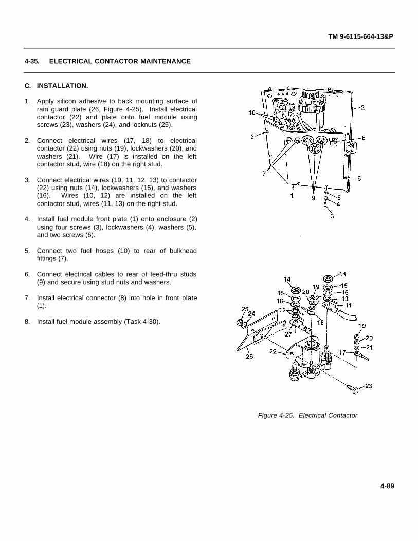
TM 9-6115-664-13&P
4-35. ELECTRICAL CONTACTOR MAINTENANCE
C. INSTALLATION.
1. Apply silicon adhesive to back mounting surface ofrain guard plate (26, Figure 4-25). Install electricalcontactor (22) and plate onto fuel module usingscrews (23), washers (24), and locknuts (25).
2. Connect electrical wires (17, 18) to electricalcontactor (22) using nuts (19), lockwashers (20), andwashers (21). Wire (17) is installed on the leftcontactor stud, wire (18) on the right stud.
3. Connect electrical wires (10, 11, 12, 13) to contactor(22) using nuts (14), lockwashers (15), and washers(16). Wires (10, 12) are installed on the leftcontactor stud, wires (11, 13) on the right stud.
4. Install fuel module front plate (1) onto enclosure (2)using four screws (3), lockwashers (4), washers (5),and two screws (6).
5. Connect two fuel hoses (10) to rear of bulkheadfittings (7).
6. Connect electrical cables to rear of feed-thru studs(9) and secure using stud nuts and washers.
7. Install electrical connector (8) into hole in front plate(1).
8. Install fuel module assembly (Task 4-30).
Figure 4-25. Electrical Contactor
4-89

TM 9-6115-664-13&P
4-36. PREHEAT MODULE ASSEMBLY MAINTENANCE
This task covers inspection and repair.
INITIAL SETUP
Tools: Equipment Condition:Shop Equipment, Automotive Maintenance APU Shut Downand Repair (Item 1, App. B) NATO Plug Disconnected
A. REMOVAL.
NOTE
Discard and replace all lockwashersand locknuts when removed.
1. Open top front cover on enclosure by turninglatches.
2. Disconnect two electrical connectors (1, 2, Figure4-26) from preheat module (3).
3. Disconnect ventilation hose (5) from preheat module(3) by loosening clamp (4). It is not necessary todisconnect hose from APU enclosure air vent.
4. Remove preheat module (3) from engine byremoving four bolts (6), lockwashers (7), andwashers (8). Remove insulating pad (9).
5. The preheat module is a non-repairable assembly.Do not attempt to remove circuit board or electricalconnectors.
B. INSPECTION.
1. Inspect electrical wiring for cuts, abrasions, and barewire. Check wiring insulation for damage.
2. Inspect electrical connectors for bent, broken, ormissing pins. Figure 4-26. Preheat Module
4-90
TM 9-6115-664-13&P
4-36. PREHEAT MODULE ASSEMBLY MAINTENANCE
C. INSTALLATION.
1. Place insulating pad (9, Figure 4-26) onto bottom of preheat module (3) and mate preheat module to engine. Secureusing four bolts (6), lockwashers (7), and washers (8).
2. Connect electrical connectors (1, 2) to preheat module (3).
3. Connect ventilation hose (5) to preheat module (3) and tighten clamp (4).
4. Close top front cover and lock using latches.
4-91

TM 9-6115-664-13&P
4-37. VOLTAGE REGULATOR MAINTENANCE
This task covers inspection and repair.
INITIAL SETUP
Tools: Equipment Condition:Shop Equipment, Automotive Maintenance APU Shut Downand Repair (Item 1, App. B) NATO Plug Disconnected
A. REMOVAL.
NOTE
Discard and replace all lockwashersand locknuts when removed.
1. Open top rear cover on enclosure by turning latches.
2. Disconnect electrical connector (1, Figure 4-27) fromvoltage regulator (2).
3. Remove voltage regulator (2) from alternator byremoving screw (3), lockwasher (4), and washer (5).
4. Remove voltage regulator (2) from fan shroud byremoving screws (6), lockwashers (7), and washers(8).
5. Remove mounting bracket (9) from voltage regulator(2) by removing three screws (10), washers (11, 12),and locknuts (13).
B. INSPECTION.
1. Inspect electrical wiring for cuts, abrasions, and barewire. Check wiring insulation for damage.
2. Inspect electrical connector for bent, broken, ormissing pins.
3. Inspect voltage regulator for obvious damage.
Figure 4-27. Voltage Regulator
4-92

TM 9-6115-664-13&P
4-37. VOLTAGE REGULATOR MAINTENANCE
C. INSTALLATION.
1. Mate mounting bracket (9, Figure 4-27) to voltage regulator (2) and secure using three screws (10), washers (11, 12),and locknuts (13).
2. Secure voltage regulator (2) to alternator using screw (3), lockwasher (4), and washer (5).
3. Secure voltage regulator (2) to fan shroud using screws (6), lockwashers (7), and washers (8).
4. Connect electrical connector (1) to voltage regulator (2).
5. Close top rear cover and lock using latches.
4-93

TM 9-6115-664-13&P
4-38. OIL COOLER HOSE ASSEMBLY MAINTENANCE
This task covers inspection and repair.
INITIAL SETUP
Tools: Equipment Condition:Shop Equipment, Automotive Maintenance Engine Oil Drained (App. F)and Repair (Item 1, App. B)
A. REMOVAL.
NOTE
Have a supply of clean rags availableto soak up oil. Place rags inside APUenclosure, below fittings, beforedisconnecting hose assemblies.
NOTE
Discard and replace all lockwashersand locknuts when removed.
1. Open oil filter access door (1, Figure 4-28) by turningdoor latches.
2. Remove air outlet header (2) from APU enclosure byremoving six screws (3), lockwashers (4), andwashers (5).
3. Disconnect oil cooler hose assemblies (9, 10) fromelbows (6, 7) and oil cooler (8). Remove elbows (6,7) from oil filter adapter only if replacement isrequired.
B. INSPECTION.
1. Inspect oil cooler hoses for punctures, cuts, tears, orevidence of corrosion or leakage. Ensure hosefittings are securely attached.
2. Inspect elbows and oil cooler fittings for crossed,stripped, or flattened threads.
Figure 4-28. Oil Cooler Hoses
4-94

TM 9-6115-664-13&P
4-38. OIL COOLER HOSE ASSEMBLY MAINTENANCE
3. Inspect oil cooler for obvious damage. Inspect for evidence of leakage or corrosion. Refer to next highermaintenance level for replacement of cooler.
C. INSTALLATION.
1. Install elbows (6, 7, Figure 4-28). See figure for correct orientation.
2. Connect oil cooler hose assemblies (9, 10) to elbows (6, 7) and oil cooler (8).
3. Service engine oil in accordance with Appendix F. Inspect oil cooler hoses for leaks. Secure as required.
4. Install air outlet header (2) onto APU enclosure using six screws (3), lockwashers (4), and washers (5).
5. Close oil filter access door (1) and lock door latches.
4-95
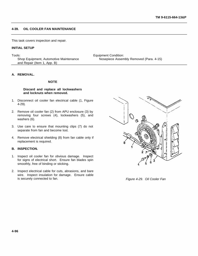
TM 9-6115-664-13&P
4-39. OIL COOLER FAN MAINTENANCE
This task covers inspection and repair.
INITIAL SETUP
Tools: Equipment Condition:Shop Equipment, Automotive Maintenance Nosepiece Assembly Removed (Para. 4-15)and Repair (Item 1, App. B)
A. REMOVAL.
NOTE
Discard and replace all lockwashersand locknuts when removed.
1. Disconnect oil cooler fan electrical cable (1, Figure4-29).
2. Remove oil cooler fan (2) from APU enclosure (3) byremoving four screws (4), lockwashers (5), andwashers (6).
3. Use care to ensure that mounting clips (7) do notseparate from fan and become lost.
4. Remove electrical shielding (8) from fan cable only ifreplacement is required.
B. INSPECTION.
1. Inspect oil cooler fan for obvious damage. Inspectfor signs of electrical short. Ensure fan blades spinsmoothly, free of binding or sticking.
2. Inspect electrical cable for cuts, abrasions, and barewire. Inspect insulation for damage. Ensure cableis securely connected to fan. Figure 4-29. Oil Cooler Fan
4-96

TM 9-6115-664-13&P
4-39. OIL COOLER FAN MAINTENANCE
C. TESTING.
Connect a 24VDC power source to the fan electrical terminals. Check that the fan blade spins. Replace fan if bladedoes not spin.
D. INSTALLATION.
1. Mate oil cooler fan (2, Figure 4-29) to APU enclosure (3). Secure using four screws (4), lockwashers (5), andwashers (6).
2. Feed electrical cable (1) through hole in APU enclosure (3). Connect electrical cable and ty-wrap to secure.
NOTE
Ensure that electrical shielding (8) is replaced in original location (close to the fan)on fan cable.
3. Install electrical shielding (8) on fan cable.
4. Install nosepiece assembly (Para. 4-15).
4-97

TM 9-6115-664-13&P
4-40. EXTERNAL MUFFLER MAINTENANCE
This task covers inspection and repair.
INITIAL SETUP
Tools: Equipment Condition:Shop Equipment, Automotive Maintenance APU Shut Down and Coldand Repair (Item 1, App. B) NATO Plug Disconnected
Parts/Materials:Adhesive, Silicon (Item 2, App. E)Anti-Seize Compound (Item 3, App. E)
A. REMOVAL.
WARNING
External muffler and cover may be hot. Use caution when handling to preventbums. Allow time for parts to cool before removing.
NOTE
Discard and replace all lockwashers and locknuts when removed.
1. Remove muffler cover (1, Figure 4-30) from housing (2) by removing four screws (3), lockwashers (4), washers (5),and spacers (6).
2. Remove external muffler (8) from exhaust assembly nuts by removing two screws (9), lockwashers (10), and washers(11).
3. Remove rain cap (12) from muffler (8) by loosening clamp (13).
4. If replacement is required, remove housing (2) from APU enclosure by removing two screws (14), lockwashers (15),and washers (16). These screws also secure the internal exhaust assembly to the APU enclosure.
B. INSPECTION.
1. Inspect muffler cover and housing for dents, cracks, warping, or other damage. Inspect painted surfaces for chips,scratches, bare metal, roughness, or corrosion.
2. Inspect silicon seal (7) for damage. Ensure secure attachment. Replace as required using silicon adhesive.
4-98

TM 9-6115-664-13&P
4-40. EXTERNAL MUFFLER MAINTENANCE
3. Inspect housing gasket for damage. Ensure secureattachment. Replace as required using siliconadhesive.
4. Inspect external muffler for clogs, holes, cracks, orother damage. Check for corrosion.
C. INSTALLATION.
1. Apply anti-seize compound to threads of two screws(14, Figure 4-30). Secure housing (2) to APUenclosure using screws (14), lockwashers (15), andwashers (16). These screws also secure internalexhaust assembly to the inside of the APUenclosure.
2. Fit rain cap (12) and clamp (13) onto external muffler(8). Secure by tightening clamp.
3. Mate external muffler (8) to exhaust assembly airduct.
4. Apply anti-seize compound to threads of two screws(9). Secure muffler (8) using screws (9),lockwashers (10), and washers (11).
5. Apply anti-seize compound to threads of four screws(3). Install muffler cover (1) using screws (3),lockwashers (4), washers (5), and spacers (6).
Figure 4-30. External Muffler
4-99

TM 9-6115-664-13&P
4-41. INTERNAL EXHAUST ASSEMBLY MAINTENANCE
This task covers inspection and repair.
INITIAL SETUP
Tools: Equipment Condition:Shop Equipment, Automotive Maintenance External Muffler Removed (Para. 4-40)and Repair (Item 1, App. B) In-Line Fuel Filter Detached From Mounting
Bracket (Para. 4-44)Parts/Materials: APU Cover Assembly Removed (Para. 4-12)
Adhesive, Silicon (Item 2, App. E) Fuel Module Removed (Para. 4-30)Anti-Seize Compound (Item 3, App. E)Safety Wire (Item 13, App. E)
A. REMOVAL.
WARNING
Internal exhaust assembly may be hot. Use caution when handling to preventbums. Allow time for parts to cool before removing.
NOTE
Discard and replace all lockwashers and locknuts when removed.
1. Disconnect exhaust inlet hose (1, Figure 4-31) from fan shroud (2) by loosening clamp (3).
2. Disconnect flexible exhaust hose (4) from adapter pipe (6) by loosening clamp (5).
3. Remove exhaust assembly (11) from APU enclosure by removing two screws (12), lockwashers (13), and washers(14). These screws also secure external muffler housing (16).
4. Remove muffler blanket from exhaust assembly (11).
5. Remove and discard safety wire that secures insulating wrap on exhaust pipe (10) and adapter pipe (6). Removeinsulating wrap.
6. Loosen hose clamp (7) and disconnect engine exhaust hose from adapter pipe (6).
7. Disconnect adapter pipe (6) from exhaust pipe (5) by removing screws (8) and lockwashers (9).
B. INSPECTION.
1. Inspect exhaust assembly for holes, dents, cracks, warping, or other damage. Inspect for corrosion.
4-100

TM 9-6115-664-13&P
4-41. INTERNAL EXHAUST ASSEMBLY MAINTENANCE
2. Inspect muffler blanket for damage. Check securityof attachment.
3. Inspect silicon seal (15) on housing (16) for damage.Ensure secure attachment. Replace as requiredusing silicon adhesive.
4. Inspect housing gasket (17) for damage. Ensuresecure attachment. Replace as required usingsilicon adhesive.
C. INSTALLATION.
1. Install muffler blanket onto internal exhaustassembly (7, Figure 4-31).
2. Mate adapter pipe (6) to exhaust pipe (5) and secureusing screws (8) and lockwashers (9).
3. Wrap insulating wrap around exhaust pipe (5) andadapter pipe (6). Secure using safety wire.
4. Apply anti-seize compound to threads of two screws(12). Install exhaust assembly (11) and housing (16)to APU enclosure using screws (12), lockwashers(13), and washers (14).
5. Connect exhaust inlet hose (1) to fan shroud hose(2) and tighten clamp (3).
6. Connect flexible exhaust hose (4) to adapter pipe(6). Secure using hose clamp (5).
7. Install external muffler (Para. 4-40). Attach inlinefuel filter to mounting bracket (Para. 4-44).
8. Install fuel module (Para. 4-30). Install APU coverassembly (Para. 4-12).
Figure 4-31. Exhaust Assembly
4-101

TM 9-6115-664-13&P
4-42. ENGINE EXHAUST DUCT ASSEMBLY MAINTENANCE
This task covers inspection and repair.
INITIAL SETUP
Tools: Equipment Condition:Shop Equipment, Automotive Maintenance Air Filter and Filter Base Removed (Para. 4-43)and Repair (Item 1, App. B)
Parts/Materials:Adhesive, Silicon (Item 2, App. E)
A. REMOVAL.
WARNING
Make sure that electrical cable isdisconnected from NATO receptaclebefore performing any maintenanceaction. Failure to do so can result inelectrical shock.
NOTE
Discard and replace all lockwashersand locknuts when removed.
1. Remove screw (10, Figure 4-32), washer (11), andlockwasher (12) and release engine exhaust bellows(1) from air duct (2, located in valve access door).
2. If replacement is required, remove exhaust bellows(1) from air outlet duct (3) by drilling out rivets.
3. Remove two bolts (4), lockwashers (5), and washers(6).
4. Remove air outlet duct (3) by removing two bolts (7),lockwashers (8), and washers (9). Figure 4-32. Exhaust Duct
4-102
TM 9-6115-664-13&P
4-42. ENGINE EXHAUST DUCT ASSEMBLY MAINTENANCE
B. INSPECTION.
1. Inspect exhaust bellows for cuts, tears, or other damage. Ensure bellows material is sound.
2. Inspect air outlet duct for holes, dents, cracks, warping, or other damage. Inspect for corrosion.
C. INSTALLATION.
1. Remove old silicon adhesive from air outlet duct (3, Figure 4-32). Make sure that mating surfaces are clean.
2. Fit air outlet duct (3) in place around cylinder head. Secure using two bolts (7), lockwashers (8), and washers (9).
3. Install two bolts (4), lockwashers (5), and washers (6). Apply a silicon bead to exposed edges of air outlet duct (3) toseal junction of duct and cylinder head.
4. Apply a thin layer of silicon to lip of air outlet duct (3) where it mates with exhaust bellows (1).
5. Install exhaust bellows (1) onto air outlet duct (3) using new rivets.
6. Mate exhaust bellows (1) to air duct (2, located in valve access door). Secure using screw (10), washer (11), andlockwasher (12).
7. Install engine air filter and filter base (Para. 4-43).
4-103

TM 9-6115-664-13&P
4-43. ENGINE AIR FILTER MAINTENANCE
This task covers inspection and repair.
INITIAL SETUP
Tools: Equipment Condition:Shop Equipment, Automotive Maintenance APU Shut Downand Repair (Item 1, App. B) NATO Plug Disconnected
Parts/Materials:Adhesive, Loctite (Item 1, App. E)
A. REMOVAL.
WARNING
Make sure that electrical cable is disconnected from NATO receptacle beforeperforming any maintenance action. Failure to do so can result in electrical shock.
NOTE
Discard and replace all lockwashers and locknuts when removed.
1. Open top front cover on APU enclosure by turning latches.
2. Disconnect engine air hose (1, Figure 4-33) from air duct on inside wall of APU enclosure.
3. Release filter cover (2) from filter base (4) by unscrewing wing screw assembly (5).
4. Remove filter cover (2) and filter (8) from filter base (4). Remove wing screw assembly (5), washer (6), and retainer(7) only if replacement is required.
5. Remove filter base (4), backing plate (14), and gasket (18) by removing nut (9), three bolts (11), and threelockwashers (12). Remove set screw (13).
6. If replacement of intake guard (10) is required, remove filter base (4) from backing plate (14) by removing threescrews (15), six washers (16), and three nuts (17).
B. INSPECTION.
1. Inspect engine air hose for cuts, tears, or other damage. Replace hose as required by loosening clamp (3).
2. Inspect air filter cover and base for dents, cracks, warping, or other damage. Inspect for corrosion.
4-104

TM 9-6115-664-13&P
4-43. ENGINE AIR FILTER MAINTENANCE
3. Inspect intake guard for damage. Ensure meshscreen is intact. Replace as required.
C. INSTALLATION.
NOTE
Screws (15, Figure 4-33) are installedfrom different sides of the filter base.Screw in rear hole mounts from thetop of the filter base. Two screws infront holes mount from below thefilter base.
1. Mate filter base (4) to backing plate (14). Secureusing three screws (15), six washers (16), and threenuts (17).
2. Apply loctite adhesive to threads of bolts (11) andboth ends of setscrew (13). Install filter base (4) andbacking plate (14) using three bolts (11) andlockwashers (12). Install setscrew (13) and nut (9).
3. If removed, install wing screw assembly (5) andwasher (6) onto filter cover (2) using retainer (7).
4. Install filter (8) and filter cover (2) onto base (4).Ensure filter is properly seated.
5. Secure filter cover (2) to base (4) by screwing inwing screw assembly (5).
6. Connect engine air hose (1) to filter cover (2) andenclosure duct. Secure by tightening clamps (3).
7. Close top front cover and lock using latches.
Figure 4-33. Engine Air Filter
4-105

TM 9-6115-664-13&P
4-44. FUEL FILTER (IN-LINE) MAINTENANCE
This task covers removal, inspection, and installation
INITIAL SETUP
Tools: Equipment Condition:Shop Equipment, Automotive Maintenance APU Shut Downand Repair (Item 1, App. B) NATO Plug Disconnected
Parts/Materials:Adhesive, Loctite (Item 1, App. E)
A. REMOVAL.
WARNING
Make sure that electrical cable isdisconnected from NATO receptaclebefore performing any maintenanceaction. Failure to do so can result inelectrical shock.
NOTE
Discard and replace all lockwashersand locknuts when removed.
1. Open top rear cover on APU enclosure by turninglatches.
2. Loosen clamps (4, Figure 4-34) and disconnect fuelhoses (1, 2) from fuel filter (5). Separate fuel hose(3), if required, by cutting tie-wraps.
3. Remove fuel filter (5) from filter bracket (7) byloosening clamp (6).
4. Remove filter bracket (7) from mounting bracket (8)by removing screw (9), washers (10), and locknut(11).
5. Remove mounting bracket (8) from flywheel housingby removing bolt (12), lockwasher (13), and washer(14).
Figure 4-34. In-Line Fuel Filter
4-106

TM 9-6115-664-13&P
4-44. FUEL FILTER (IN-LINE) MAINTENANCE
B. INSPECTION.
1. Inspect fuel hoses for punctures, cuts, tears, deterioration, or other damage. Check for evidence of fluid leakage.
2. Inspect fuel filter for dents, cracks, scratches, or other damage. Inspect for corrosion and evidence of leakage.
C. INSTALLATION.
1. Apply loctite to threads of bolt (12, Figure 4-34). Install mounting bracket (8) to flywheel housing using bolt (12),lockwasher (13), and washer (14).
2. Mate fuel filter bracket (7) to mounting bracket (8) and secure using screw (9), washers (10), and locknut (11).
3. Install fuel filter (5) into bracket (7), ensuring proper positioning. Secure by tightening clamp (6).
4. Connect fuel hoses (1, 2) to fuel filter (5) and tighten clamps (4).
5. Close top rear cover and lock using latches.
4-107

TM 9-6115-664-13&P
4-45. ENGINE START SOLENOID / MANUAL START SWITCH MAINTENANCE
This task covers removal, inspection, installation, and adjustment
INITIAL SETUP
Tools: Equipment Condition:Shop Equipment, Automotive Maintenance APU Shut Downand Repair (Item 1, App. B) NATO Plug Disconnected
Parts/Materials:Adhesive, Loctite (Item 1, App. E)
A. REMOVAL.
WARNING
Make sure that electrical cable isdisconnected from NATO receptaclebefore performing any maintenanceaction. Failure to do so can result inelectrical shock.
NOTE
Discard and replace all lockwashersand locknuts when removed.
1. Open top front cover on APU enclosure by turninglatches.
2. Disconnect solenoid electrical connector (1, Figure4-35).
3. Open oil filter access door. Depress top of solenoid(2). Disengage and remove clip (3) to releasesolenoid from engine throttle control.
4. Remove solenoid (2) from mounting bracket (4) byremoving two screws (5), lockwashers (6), and nuts(7).
5. Tag and disconnect manual start switch electricalconnector (8). Figure 4-35. Solenoid and Start Switch
4-108

TM 9-6115-664-13&P
4-45. ENGINE START SOLENOID / MANUAL START SWITCH MAINTENANCE
6. Remove manual start switch (9) from mounting bracket (4) by removing nut (10) and star washer (11).
7. Remove mounting bracket (4) from engine by removing two screws (12) and spacers (13).
B. INSPECTION.
1. Inspect electrical wires for cuts, abrasions, or bare wire. Inspect wire insulation for damage. Ensure wiring issecurely attached to solenoid and start switch.
2. Inspect solenoid for dents, cracks, scratches, or other damage. Inspect for corrosion.
C. INSTALLATION.
1. Install mounting bracket (4, Figure 4-35) onto engine using two screws (12) and spacers (13).
2. Install manual start switch (9) onto mounting bracket (4) using nut (10) and star washer (11).
3. Mate solenoid (2) to mounting bracket (4). Secure by loosely installing two screws (5), lockwashers (6), and nuts (7).Do not tighten at this time.
4. Thread solenoid yoke approximately half-way onto solenoid shaft. Mate yoke to engine throttle control. Thread yokeup or down as required to ensure proper mating.
5. Once mated, insert pin on clip (3) into engine throttle control and solenoid (2). Depress top of solenoid and snap clipinto place to secure. Adjust solenoid as required in accordance with paragraph D.
6. Connect solenoid and manual start switch electrical connectors (1, 9).
7. Close top front cover and lock using latches.
D. ADJUSTMENT.
1. Manually operate solenoid (2, Figure 4-35) to ensure that linkage moves freely. Tighten screws (5) and nuts (7) tosecurely fasten solenoid to mounting bracket (4).
2. Depress top of solenoid (2) until it reaches maximum travel length and stops. Throttle lever shall be 1/32 inch fromthe mechanical stop on engine.
3. Adjust yoke as required to obtain proper clearance. Tighten yoke nut to secure yoke in place once clearance hasbeen achieved.
4-109
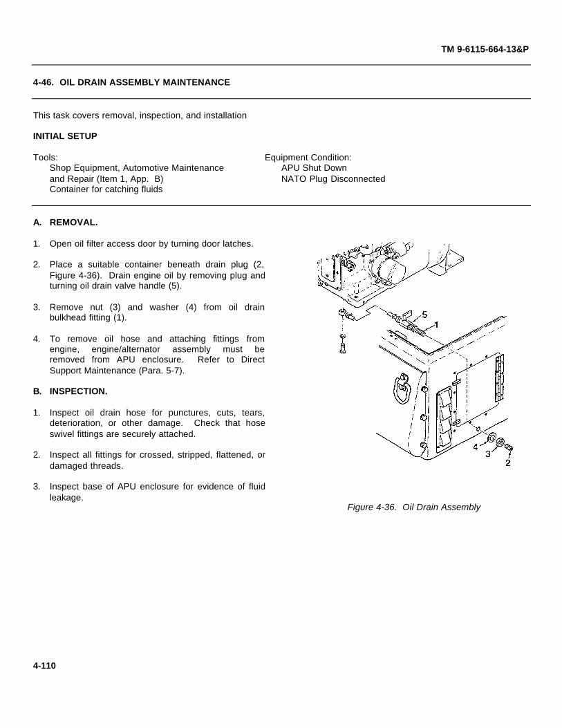
TM 9-6115-664-13&P
4-46. OIL DRAIN ASSEMBLY MAINTENANCE
This task covers removal, inspection, and installation
INITIAL SETUP
Tools: Equipment Condition:Shop Equipment, Automotive Maintenance APU Shut Downand Repair (Item 1, App. B) NATO Plug DisconnectedContainer for catching fluids
A. REMOVAL.
1. Open oil filter access door by turning door latches.
2. Place a suitable container beneath drain plug (2,Figure 4-36). Drain engine oil by removing plug andturning oil drain valve handle (5).
3. Remove nut (3) and washer (4) from oil drainbulkhead fitting (1).
4. To remove oil hose and attaching fittings fromengine, engine/alternator assembly must beremoved from APU enclosure. Refer to DirectSupport Maintenance (Para. 5-7).
B. INSPECTION.
1. Inspect oil drain hose for punctures, cuts, tears,deterioration, or other damage. Check that hoseswivel fittings are securely attached.
2. Inspect all fittings for crossed, stripped, flattened, ordamaged threads.
3. Inspect base of APU enclosure for evidence of fluidleakage.
Figure 4-36. Oil Drain Assembly
4-110

TM 9-6115-664-13&P
4-46. OIL DRAIN ASSEMBLY MAINTENANCE
C. INSTALLATION.
1. Insert oil drain assembly bulkhead fitting (1, Figure4-36) through hole in enclosure. Secure using nut(3) and washer (4).
2. Install allen head plug (2) and close oil drain valveby turning handle.
3. Service engine oil (Para. 4-1). Check oil draincomponents for leakage and tighten as required.
4-111

(Figure 4-37 Sheet 1 of 2)(Figure 4-37 Sheet 2 of 2)
TM 9-6115-664-13&P
4-47. VALVE CLEARANCE ADJUSTMENT
This task covers adjustment of the engine valves/rockers
INITIAL SETUP
Tools: Equipment Condition:Shop Equipment, Automotive Maintenance APU Shut Down and Coldand Repair (Item 1, App. B) NATO Plug Disconnected
A. ADJUSTMENT.
NOTE
Discard and replace all lockwashersand locknuts when removed.
1. Open top front cover on APU enclosure by turninglatches.
2. Disconnect engine exhaust bellows (1, Figure 4-37)from rear of valve access door (2) by removingscrew (3), lockwasher (4), and washer (5).Disconnect air hose (6) only if replacement isrequired.
3. Open valve access door (2) by turning door latches.
4. Place rags below rocker cover to capture fluids.Wipe spills with a clean rag.
NOTE
When removing rocker cover (7), tiltback towards you to prevent captureoil from spilling inside APUenclosure.
5. Remove rocker cover (7) by removing screws (8).Dislodge washers (9) from cover by tapping lightlywith tip of screwdriver. Discard washers and gasket(10).
Figure 4-37. Valve Clearance Adjustment(Sheet 1 of 2)
4-112
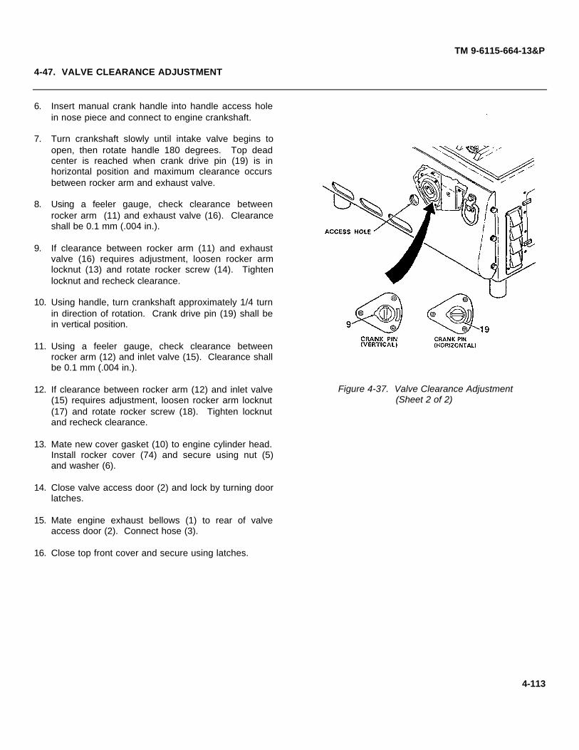
TM 9-6115-664-13&P
4-47. VALVE CLEARANCE ADJUSTMENT
6. Insert manual crank handle into handle access holein nose piece and connect to engine crankshaft.
7. Turn crankshaft slowly until intake valve begins toopen, then rotate handle 180 degrees. Top deadcenter is reached when crank drive pin (19) is inhorizontal position and maximum clearance occursbetween rocker arm and exhaust valve.
8. Using a feeler gauge, check clearance betweenrocker arm (11) and exhaust valve (16). Clearanceshall be 0.1 mm (.004 in.).
9. If clearance between rocker arm (11) and exhaustvalve (16) requires adjustment, loosen rocker armlocknut (13) and rotate rocker screw (14). Tightenlocknut and recheck clearance.
10. Using handle, turn crankshaft approximately 1/4 turnin direction of rotation. Crank drive pin (19) shall bein vertical position.
11. Using a feeler gauge, check clearance betweenrocker arm (12) and inlet valve (15). Clearance shallbe 0.1 mm (.004 in.).
12. If clearance between rocker arm (12) and inlet valve(15) requires adjustment, loosen rocker arm locknut(17) and rotate rocker screw (18). Tighten locknutand recheck clearance.
13. Mate new cover gasket (10) to engine cylinder head.Install rocker cover (74) and secure using nut (5)and washer (6).
14. Close valve access door (2) and lock by turning doorlatches.
15. Mate engine exhaust bellows (1) to rear of valveaccess door (2). Connect hose (3).
16. Close top front cover and secure using latches.
Figure 4-37. Valve Clearance Adjustment(Sheet 2 of 2)
4-113

(Figure 4-38 Sheet 1 of 2)(Figure 4-38 Sheet 2 of 2)
TM 9-6115-664-13&P
4-48. FUEL INJECTOR MAINTENANCE
This task covers removal, inspection, and installation
INITIAL SETUP
Tools Equipment Condition:Shop Equipment, Automotive Maintenance APU Shut Downand Repair (Item 1, App. B) NATO Plug Disconnected
A. REMOVAL.
NOTE
Discard and replace all lockwashersand locknuts when removed.
1. Open top front cover on APU enclosure by turninglatches.
2. Disconnect engine exhaust bellows (1, Figure 4-38)from rear of valve access door (2) by removingscrew (3), lockwasher (4), and washer (5).Disconnect air hose (6) only if replacement isrequired.
3. Open valve access door (2) by turning door latches.
4. Disconnect fuel pipe (13) from fuel injector (14).
5. Disconnect fuel pipe (9) from fuel injector (14) byremoving banjo bolt (10) and washers (11, 12).
6. Remove fuel injector flange by removing nuts (7)and washers (8).
Figure 4-38. Fuel Injector (Sheet 1 of 2)
4-114

TM 9-6115-664-13&P
4-48. FUEL INJECTOR MAINTENANCE
7. Remove injector (14) and gasket (15). Discardgasket.
8. Inspect injector nozzle (16) for contaminants. Checkthat nozzle orifice is clear (allowing a proper spraypattern). If nozzle is damaged or worn, remove andreplace nozzle.
9. Remove studs (17) from cylinder head only ifreplacement is required.
B. INSPECTION.
1. Inspect engine fuel hoses for punctures, cuts, tears,deterioration, or other damage. Check that hosefittings are securely attached.
2. Inspect fuel injector for damage. Check for scoringor signs of excessive heat. Inspect injector orificesfor clogging. Clear as required.
C. INSTALLATION.
1. If removed, install studs (17, Figure 4-38) intocylinder head.
2. Install new gasket (15) onto fuel injector (14). Installfuel pipe (9) using banjo bolt (10) and washers (11,12).
3. Insert injector (14) into cylinder head port. Orient asshown in Figure 4-38. Install injector flange (9) andsecure using nuts (7) and washers (8). Torque nutsto 15 to 17 ft-lbs (20 to 23 Nm).
4. Connect fuel pipe (13) to fuel injector (14).
5. Close valve access door (2) and lock by turning doorlatches. Mate engine exhaust bellows (1) to rear ofdoor and secure using screw (3), lockwasher (4),and washer (5).
6. Close top front cover and secure using latches.
Figure 4-38. Fuel Injector (Sheet 2 of 2)
4-115

TM 9-6115-664-13&P
4-49. OIL LEVEL DIPSTICK MAINTENANCE
This task covers removal, inspection, and installation
INITIAL SETUP
Tools: Equipment Condition:Shop Equipment, Automotive Maintenance APU Shut Downand Repair (Item 1, App. B) NATO Plug Disconnected
A. REMOVAL.
1. Open top front cover on APU enclosure by turninglatches.
2. Remove oil level dipstick (1, Figure 4-39) fromengine port (2).
B. INSPECTION.
1. Inspect engine oil dipstick for damage. Check forbent or twisted level rod. Inspect for corrosion.
2. Inspect dipstick O-rings for cuts, tears, deformation,damage, or signs of deterioration. Replace asrequired.
3. Inspect area around oil level dipstick for evidence ofleakage.
C. INSTALLATION.
1. Insert oil level dipstick (1, Figure 4-39) into engineport (2).
2. Close top front cover and secure by locking latches.
Figure 4-39. Oil Level Dipstick
4-116

TM 9-6115-664-13&P
4-50. OIL FILTER MAINTENANCE
This task covers removal, inspection, and installation
INITIAL SETUP
Tools: Equipment Condition:Oil Filter Wrench (4, App. B) Engine Oil Drained (Para. 4-1)
A. REMOVAL.
1. Open oil filter access door by turning door latches.
2. Using oil filter wrench, remove oil filter (1, Figure4-40) from oil filter fitting (2). Discard oil filter.
B. INSPECTION.
1. Inspect oil filter fitting for damage. Inspect forcrossed, stripped, or flattened threads. Inspectvalve orifice for clogging and clean as required.
2. Inspect area around oil cover for evidence ofleakage.
C. INSTALLATION.
1. Apply a light coat of engine oil to oil filter gasket toease filter installation. Install new oil filter (1, Figure4-40) and hand tighten.
2. Service engine oil (Para. 4-1). Inspect area aroundoil filter for leakage and tighten as required.
3. Close oil filter access door and lock using doorlatches.
Figure 4-40. Oil Filter
4-117

TM 9-6115-664-13&P
4-51. OIL PRESSURE VALVE / OIL COVER MAINTENANCE
This task covers removal, inspection, and installation
INITIAL SETUP
Tools: Equipment Condition:Shop Equipment, Automotive Maintenance Oil Cooler Hoses Disconnected from Oiland Repair (Item 1, App. B) Filter Adapter (Para. 4-38)3/4 Inch SAE Thread Jam Nuts (2 each)
A. REMOVAL.
1. Open oil filter access door by turning door latches.
2. Using oil filter wrench, remove oil filter (1, Figure4-41) from oil filter fitting (2). Discard oil filter.
3. Remove oil filter fitting (2) and filter adapter (3).Remove and discard gasket (4, on rear of adapter).
4. Install two 3/4 inch SAE thread jam nuts on oilpressure valve (5). Remove valve from oil cover (6)by wrenching jam nuts.
NOTE
Remove oil cover only if replacementof cover or gasket is required.
5. Tag and disconnect electrical wires from oil pressureswitch (7). Remove switch.
6. If removal of oil cover (6) is required, you must firstremove engine starter motor (Para. 4-53).
7. Remove oil cover (6) from engine crankcase byremoving four screws (8) and washers (9). Removeand discard gasket (10).
Figure 4-41. Oil Pressure Valve and Cover
4-118

TM 9-6115-664-13&P
4-51. OIL PRESSURE VALVE / OIL COVER MAINTENANCE
B. INSPECTION.
1. Inspect oil filter adapter and pressure valve for damage. Inspect for crossed, stripped, or flattened threads. Inspectvalve orifice for clogging and clean as required.
2. Inspect area around oil cover for evidence of leakage. Inspect oil cover for cracks, scratches, or other damage.Inspect sealing surfaces for damage that will prevent proper seal.
C. INSTALLATION.
1. Apply grease to oil seal (11, Figure 4-41) and install in position on oil cover (6). Mate new cover gasket (10) to oilcover (6). Mate oil cover to engine crankcase and secure using four screws (8) and washers (9).
2. Install oil pressure valve (5) into oil cover (6).
3. Install oil pressure switch (7) and connect electrical wires.
CAUTION
Do not overtighten oil filter fitting (2). Damage to fitting and adapter (3) will result.
4. Install new gasket (4) onto rear of filter adapter (3). Install adapter and oil filter fitting (2). Tighten to 18.5 ft-lbs (25 Nm).
5. Apply a light coat of engine oil to oil filter gasket to ease filter installation. Install new oil filter (1) and hand tighten.
6. Connect oil cooler hoses to elbows on oil filter adapter (Para. 4-38).
7. Service engine oil (Para. 4-1). Inspect area around oil filter and oil cover for leakage and tighten as required.
8. Close oil filter access door and lock using door latches.
4-119

TM 9-6115-664-13&P
4-52. OIL PRESSURE SWITCH MAINTENANCE
This task covers removal, inspection, and installation
INITIAL SETUP
Tools: Equipment Condition:Shop Equipment, Automotive Maintenance APU Shut Downand Repair (Item 1, App. B) NATO Plug Disconnected
A. REMOVAL.
1. Open oil filter access door by turning door latches.
2. Disconnect electrical leads (1, Figure 4-42) from oilpressure switch (2).
3. Unscrew oil pressure switch (2) from engine oilcover.
B. INSPECTION.
1. Inspect oil pressure switch for damage. Inspect forcrossed, stripped, or flattened threads.
2. Inspect electrical wires for cuts, abrasions, barewires, or corrosion. Inspect wire insulation fordamage.
C. INSTALLATION.
1. Install oil pressure switch (2, Figure 4-42) intoengine oil cover.
2. Connect electrical leads (1) to oil pressure switch(2).
3. Close oil filter access door and lock using doorlatches.
Figure 4-42. Oil Pressure Switch
4-120

(Figure 4-43 Sheet 1 of 2)(Figure 4-43 Sheet 2 of 2)
TM 9-6115-664-13&P
4-53. OIL FILL TUBE MAINTENANCE
This task covers removal, inspection, and installation
INITIAL SETUP
Tools: Equipment Condition:Shop Equipment, Automotive Maint enance APU Shut Downand Repair (Item 1, App. B) NATO Plug Disconnected
A. REMOVAL.
1. Open top front cover from APU enclosure by turninglatches.
2. Remove cap (1, Figure 4-43) from oil fill tube (2).Inspect cap gasket (3) and discard if damaged.
3. Remove oil fill tube (2) from engine by removingthree screws (4) and washers (5). Remove gasket(6).
4. If required, remove lanyard (7) from cap (1) byremoving screw (8).
B. INSPECTION.
1. Inspect cap and fill tube for damage. Inspect forcrossed, stripped, or flattened threads. Check forcorrosion of contaminant build-up.
2. Inspect fill tube gasket for cuts, tears, deformation,deterioration, or signs of permanent set. Replace ifany signs of damage.
Figure 4-43. Oil Fill Tube (Sheet 1 of 2)
4-121

TM 9-6115-664-13&P
4-53. OIL FILL TUBE MAINTENANCE
C. INSTALLATION.
1. Mate gasket (6, Figure 4-43) to engine oil port.Install oil fill tube (2) using three screws (4) andwashers (5).
2. If required, install new gasket (3) into cap (1). Screwcap onto oil fill tube (2).
3. If removed, secure lanyard (7) to cap (1) using screw(8).
4. Close top front cover and secure by locking latches.
Figure 4-43. Oil Fill Tube (Sheet 2 of 2)
4-122

(Figure 4-44 Sheet 1 of 2)(Figure 4-44 Sheet 2 of 2)
TM 9-6115-664-13&P
4-54. STARTER MAINTENANCE
This task covers removal, inspection, and installation
INITIAL SETUP
Tools: Equipment Condition:Shop Equipment, Automotive Maintenance APU Cover Assembly Removed (Para. 4-12)and Repair (Item 1, App. B) Engine Start Solenoid Removed (Para. 4-45)
A. REMOVAL.
NOTE
Discard and replace all lockwashersand locknuts when removed.
1. Pull back rubber boot (1, Figure 4-44) to expose wirelug (2). Remove nut (3), lockwasher (4), and washer(5).
2. Tag electrical wire (6). Disconnect wire from starterby removing screw (7).
3. Remove starter (8) from engine by removing screws(9, 10).
4. Remove bushing only if damaged. Remove bydriving out of crankcase using a hammer and punch.
B. INSPECTION.
1. Inspect starter for obvious damage. Inspect forcorrosion and signs of electrical short. Inspectstarter shaft for damage.
2. Inspect bushing in crankcase for scoring,deformation, or excessive wear.
3. Inspect electrical wires for cuts, abrasions, barewires, or corrosion. Inspect wire insulation fordamage.
Figure 4-44. Engine Starter (Sheet 1 of 2)
4-123

TM 9-6115-664-13&P
4-54. STARTER MAINTENANCE
C. INSTALLATION.
1. If removed, install bushing by pressing intocrankcase.
2. Mate motor (8, Figure 4-44) to engine, ensuringmotor shaft meshes with flywheel ring gear. Securemotor using screws (9, 10).
3. Connect electrical wire (6) to starter (8) using screw(7).
4. Pull back rubber boot (1) to expose wire lug (2).Install lug onto solenoid stud and secure using nut(3), lockwasher (4), and washer (5).
5. Install engine start solenoid (Para. 4-45). InstallAPU cover assembly (Para. 4-12).
Figure 4-44. Engine Starter (Sheet 2 of 2)
4-124

TM 9-6115-664-13&P
4-55. MECHANICAL FUEL PUMP MAINTENANCE
This task covers removal, inspection, and installation
INITIAL SETUP
Tools: Equipment Condition:Shop Equipment, Automotive Maintenance APU Shut Downand Repair (Item 1, App. B) NATO Plug Disconnected
A. REMOVAL.
1. Open top front cover on APU enclosure by turninglatches.
2. Remove banjo bolts (1, Figure 4-45), washers (2),fuel pipes (3), and gaskets (4) from fuel pump (5).
3. Remove fuel pump (5) from engine studs (6) byremoving two nuts (7) and washers (8). Removegasket (9).
B. INSPECTION.
1. Inspect engine fuel hose for punctures, cuts, tears,deterioration, or other damage.
2. Inspect fuel feed pump for damage. Inspect forevidence of leakage or corrosion.
3. Refer to Troubleshooting, Table 4-9, for testing ofthe mechanical fuel pump.
C. INSTALLATION.
1. Mate gasket (9, Figure 4-45) to fuel pump (5). Installpump onto studs (6) and secure using two nuts (7)and washers (8).
2. Attach fuel pipes (3) to fuel pump (5) using bolts (1),washers (2), and gaskets (4).
3. Close top front cover and secure using latches.
Figure 4-45. Mechanical Fuel Pump
4-125

TM 9-6115-664-13&P
4-56. AIR HEAT GLOW PLUG MAINTENANCE
This task covers removal, inspection, and installation
INITIAL SETUP
Tools: Equipment Condition:Shop Equipment, Automotive Maintenance Engine Air Filter Removed (Para. 4-43)and Repair (Item 1, App. B)
A. REMOVAL.
1. Disconnect electrical wires (1, 2, Figure 4-46) fromglow plugs (5) by removing nuts (3) and washers (4).
2. Unscrew two glow plugs (5) and attached spacers(6) from engine block. Retain spacers.
B. INSPECTION.
1. Inspect electrical wire for cuts, abrasions, and barewire. Check wiring insulation for damage.
2. Inspect glow plugs for obvious damage. Inspectprobe portion of plugs for cracks or signs of heatstress.
C. INSTALLATION.
1. Screw two glow plugs (5, Figure 4-46) and attachedspacers (6) into engine block.
2. Connect electrical wires (1, 2) to glow plugs (5)using nuts (3) and washers (4).
3. Install engine air filter (Para. 4-43).
Figure 4-46. Air Heat Glow Plug
4-126

TM 9-6115-664-13&P
4-57. OIL HEAT GLOW PLUG MAINTENANCE
This task covers removal, inspection, and installation
INITIAL SETUP
Tools: Equipment Condition:Shop Equipment, Automotive Maintenance APU Shut Downand Repair (Item 1, App. B) NATO Plug Disconnected
A. REMOVAL.
1. Open top front cover on APU enclosure by turninglatches.
2. Disconnect electrical wire (1, Figure 4-47) from glowplug (5) by removing nut (2), lockwasher (3), andwasher (4).
3. Unscrew glow plug (5) from engine block. Removewasher (6).
B. INSPECTION.
1. Inspect electrical wire for cuts, abrasions, and barewire. Check wiring insulation for damage.
2. Inspect glow plug for obvious damage. Inspectprobe portion of plug for cracks or signs of heatstress.
C. INSTALLATION.
1. Install glow plug (5, Figure 4-47) and washer (6) intoengine block.
2. Connect electrical wire (1) to glow plug (5) using nut(2), lockwasher (3), and washer (4).
3. Close top front cover and secure using latches.
Figure 4-47. Oil Heat Glow Plug
4-127

(Figure 4-48 Sheet 1 of 2)(Figure 4-48 Sheet 2 of 2)
TM 9-6115-664-13&P
4-58. ENGINE TEMPERATURE SWITCH MAINTENANCE
This task covers removal, inspection, and installation
INITIAL SETUP
Tools: Equipment Condition:Shop Equipment, Automotive Maintenance APU Shut Downand Repair (Item 1, App. B) NATO Plug Disconnected
A. REMOVAL.
1. Open top front cover on APU enclosure by turninglatches.
2. Disconnect engine exhaust bellows (1, Figure 4-48)from rear of valve access door (2) by removingscrew (3), lockwasher (4), and washer (5).
3. Open valve access door (2) by turning door latches.
4. Disconnect electrical wire (6) from temperatureswitch (9) by removing nut (7) and washer (8).
5. Unscrew temperature switch (9) and washer (10)from engine block.
B. INSPECTION.
1. Inspect electrical wire for cuts, abrasions, and barewire. Check wiring insulation for damage.
2. Inspect temperature switch for obvious damage.Inspect probe portion of switch for cracks or signs ofheat stress.
Figure 4-48. Temperature Switch(Sheet 1 of 2)
4-128

TM 9-6115-664-13&P
4-58. ENGINE TEMPERATURE SWITCH MAINTENANCE
C. INSTALLATION.
1. Screw temperature switch (9, Figure 4-48) andwasher (10) into engine block.
2. Connect electrical wire (6) to temperature switch (9)using nut (7) and washer (8).
3. Close valve access door (2) and lock by turning doorlatches.
4. Mate engine exhaust bellows (1) to rear of valveaccess door (2). Secure using screw (3),lockwasher (4), and washer (5).
5. Close top front cover and secure using latches.
Figure 4-48. Temperature Switch(Sheet 2 of 2)
4-129

TM 9-6115-664-13&P
4-59. HOUR METER MAINTENANCE
This task covers removal, inspection, and installation
INITIAL SETUP
Tools: Equipment Condition:Shop Equipment, Automotive Maintenance Nosepiece Assembly Removed (Para. 4-15)and Repair (Item 1, App. B)
A. REMOVAL.
NOTE
Discard and replace all lockwashersand locknuts when removed.
1. Disconnect electrical wires from hour meter (5,Figure 4-49) and circuit breaker (13).
2. Remove bracket (1) from APU enclosure byremoving screws (2), lockwashers (3), and washers(4).
3. Remove hour meter (5) and backing plate (9) frombracket (1) by removing screws (6), washers (7),nuts (8), and grommets (10).
4. Remove circuit breaker (13) from bracket (1) byremoving screws (12) and nuts (11).
B. INSPECTION.
1. Inspect electrical wire for cuts, abrasions, and barewire. Check wiring insulation for damage.
2. Inspect hour meter for obvious damage. Inspectglass for cracks. Figure 4-49. Hour Meter (Sheet 1 of 2)
4-130

TM 9-6115-664-13&P
4-59. HOUR METER MAINTENANCE
C. INSTALLATION.
1. Install circuit breaker (13, Figure 4-49) onto bracket(1) using screws (12) and nuts (11).
2. Install hour meter (5) and backing plate (9) ontobracket (1) using screws (6), washers (7), nuts (8),and grommets (10).
3. Install bracket (1) onto APU enclosure using screws(2) and washers (3).
4. Connect electrical wires to hour meter (5) and circuitbreaker (13).
5. Install nosepiece assembly (Para. 4-15).
Figure 4-49. Hour Meter (Sheet 2 of 2)
4-131

TM 9-6115-664-13&P
Section VII. PREPARATION FOR SHIPMENT AND STORAGE
4-60. GENERAL.
This section provides instructions for short term and intermediate storage or shipment of the APU.
4-61. ADMINISTRATIVE STORAGE.
Administrative storage shall be in accordance with AR 750-1.
4-62. SHORT TERM STORAGE (30 days or less).
a. Check engine oil level and service as required (Para. 4-1).
b. Check that engine crank handle is securely stowed under APU enclosure.
c. Conduct a general inspection of the unit to ensure all components are present and securely fastened. Close alldoors and lids and lock in position.
d. Stow the APU on a level surface in an area protected from the elements. Cover as required depending uponweather conditions.
4-63. INTERMEDIATE TERM STORAGE (more than 30 days).
a. Start the APU (Para. 2-8) and operate for 10 minutes at full speed to bring engine to normal operatingtemperature. Shutdown the APU.
b. Drain the engine oil (Para. 4-1). Fill crankcase to proper level with preservative lubricating oil.
c. Perform all MONTHLY PMCS requirements (Table 4-2).
d. Close air intake and exhaust openings with moisture proof tape.
e. Stow the APU on a level surface in an area protected from the elements. Cover as required depending uponweather conditions.
f. Before returning APU to service, drain preservative oil and service the engine (Para. 4-1).
4-64. SHIPMENT.
a. Close air intake and exhaust openings with moisture proof tape.
b. Attach to the APU all forms, tags, and records applicable to the unit.
c. Load APU onto carrier and attach shipping tiedowns.
4-132

TM 9-6115-664-13&P
CHAPTER 5DIRECT SUPPORT MAINTENANCE INSTRUCTIONS
Section I REPAIR PARTS; TOOLS; SPECIAL TOOLS; TEST ........................................................ 5-2MEASUREMENT, AND DIAGNOSTIC EQUIPMENT (TMDE);AND SUPPORT EQUIPMENT
5-1 Common Tools and Equipment ...................................................................................... 5-25-2 Special Tools, TMDE, and Support Equipment ................................................................ 5-25-3 Repair Parts ................................................................................................................. 5-2
Section II SERVICE UPON RECEIPT OF EQUIPMENT.................................................................. 5-2
5-4 General ........................................................................................................................ 5-2
Section I DIRECT SUPPORT TROUBLESHOOTING .................................................................... 5-3
5-5 General ........................................................................................................................ 5-35-6 Troubleshooting ............................................................................................................ 5-3
Section IV MAINTENANCE PROCEDURES ................................................................................... 5-8
5-7 Engine/Alternator Assembly Maintenance ....................................................................... 5-85-8 Engine Maintenance ................................................................................................... 5-185-9 Cylinder Head Maintenance ......................................................................................... 5-245-10 Fuel Injection Pump Maintenance ................................................................................ 5-315-11 Oil Pump Maintenance ................................................................................................ 5-345-12 Camshaft Maintenance ................................................................................................ 5-355-13 Speed Control and Primer Assembly Maintenance ........................................................ 5-375-14 Flywheel and Ring Gear Maintenance .......................................................................... 5-425-15 Cylinder, Piston, and Crankshaft Maintenance .............................................................. 5-445-16 Alternator Maintenance ............................................................................................... 5-525-17 Oil Cooler Maintenance ............................................................................................... 5-58
5-1

TM 9-6115-664-13&P
Section I. REPAIR PARTS; TOOLS; SPECIAL TOOLS; TEST,MEASUREMENT, AND DIAGNOSTIC EQUIPMENT (TMDE);
AND SUPPORT EQUIPMENT
5-1. COMMON TOOLS AND EQUIPMENT.
a. For authorized common tools and equipment, refer to the Modified Table of Organization and Equipment (MTOE),CTA 50-970, or CTA 8-100, as applicable to your unit.
b. Tool Kit, General Mechanics; Automotive, Supply Catalog SC5180-90-CL-N26, is the primary supply source fortools used in maintenance of the APU.
5-2. SPECIAL TOOLS, TMDE, AND SUPPORT EQUIPMENT.
Refer to Appendix G, Repair Parts and Special Tools List, for complete data on special tools and equipment requiredfor APU maintenance. Refer to the Maintenance Allocation Chart (MAC), Appendix B, for special tools and equipmentused at the direct support maintenance level.
5-3. REPAIR PARTS.
a. Refer to Appendix J for a list of Mandatory Replacement Parts required for general support level maintenance ofthe APU.
b. Repair parts are listed and illustrated in Appendix G, Repair Parts and Special Tools List.
Section II. SERVICE UPON RECEIPT
5-4. GENERAL.
Refer to paragraph 2-4 for instructions on unpacking, assembly, and servicing of APU components.
5-2

TM 9-6115-664-13&P
Section III. TROUBLESHOOTING
5-5. GENERAL.
This section contains direct support level troubleshooting information and tests for the APU. Troubleshootinglogic trees will aide in locating and correcting APU malfunctions. Each malfunction or trouble symptom is addressed andis followed by a series of inspections or tests necessary to determine the probable cause and corrective action.
5-6. TROUBLESHOOTING.
a. This manual can not list all possible malfunctions that may occur, all tests or inspections that may be performed,or all corrective actions for each malfunction. Only those checks and tests authorized for the direct support level arecovered. If a malfunction is not listed, or is not remedied by corrective actions, notify personnel at a higher maintenancelevel.
b. Refer to the system electrical schematic (Figure FO-1) and wiring diagrams for assistance in troubleshootingelectrical components.
c. Refer to Table 5-1, Malfunction Index, for determining applicable troubleshooting procedure.
Table 5-1. Malfunction Index
Table
Engine will not crank 5-2Engine starts but fires intermittently or dies 5-3Engine stops suddenly 5-4Engine speed fluctuates 5-5Engine hammers or knocks 5-6Engine emits black smoke 5-7
5-3

Chap. 4
Para. 5-9
Para. 5-9
Para. 5-9
Para. 5-9
Para. 5-14
Para. 5-15
TM 9-6115-664-13&P
Table 5-2. ENGINE WILL NOT CRANK
5-4

Para. 5-9
Para. 5-9
Para. 5-14
Para. 5-15
Para. 5-15
Para. 5-9
Para. 5-9
Para. 5-13
TM 9-6115-664-13&P
Table 5-3. ENGINE STARTS BUT FIRESINTERMITTENTLY OR DIES
Table 5-4. ENGINE STOPS SUDDENLY
Table 5-5. ENGINE SPEED FLUCTUATES
5-5

Para. 5-14
Para. 5-15
Para. 5-15
Para. 5-15
TM 9-6115-664-13&P
Table 5-6. ENGINE HAMMERS OR KNOCKS
5-6

Para. 5-9
Para. 5-9
Para. 5-15
TM 9-6115-664-13&P
Table 5-7. ENGINE EMITS BLACK SMOKE
5-7

TM 9-6115-664-13&P
Section IV. MAINTENANCE PROCEDURES
5-7. ENGINE/ALTERNATOR ASSEMBLY MAINTENANCE
This task covers removal, inspection, repair, and installation
INITIAL SETUP
Tools: Personnel Required:Shop Equipment, Automotive Maintenance 2 Maintenance Personneland Repair (Item 4, App. B)Lifting Hoist, 600 lb. capacity
Equipment Condition: Parts/Materials:Enclosure Lid Assembly and Brackets Adhesive, Silicon (Item 2, App. E)
Removed (Para. 4-11)Nosepiece Removed (Para. 4-15)Fuel Module Removed (Para. 4-30)Oil Cooler Hoses Disconnected (Para. 4-38)Exhaust Silencer Removed (Para. 4-41)Engine Exhaust Bellows Disconnected (Para. 4-42)In-Line Fuel Filter Disconnected (Para. 4-48)
A. REMOVAL.
WARNING
Make sure that electrical cable is disconnected from NATO receptacle beforeperforming any maintenance action. Failure to do so can result in electrical shock.
1. Disconnect electrical wiring harness from oil cooler fan connector. Disconnect wires from hour meter and circuitbreaker (Para. 4-59).
2. Remove oil drain plug (1, Figure 5-1), nut (2), and washer (3) to release oil drain assembly from APU enclosure.Remove and retain washer (4).
3. Remove air inlet hose (5) from engine air fitter (7) by loosening clamp (6).
4. Release electrical wiring harness (8) from back wall of APU enclosure by removing screws (9), nuts (10), washers(11), and nuts (12). Remove clamps (13) only if replacement is required.
5. Remove manual start switch (14) from mounting bracket (15) by removing nut (16) and washer (17).
5-8

(Figure 5-1 Sheet 1 of 5)(Figure 5-1 Sheet 2 of 5)(Figure 5-1 Sheet 3 of 5)(Figure 5-1 Sheet 4 of 5)(Figure 5-1 Sheet 5 of 5)
TM 9-6115-664-13&P
5-7. ENGINE/ALTERNATOR ASSEMBLY MAINTENANCE
Figure 5-1. Engine /Alternator Assembly(Sheet 1 of 5)
5-9

TM 9-6115-664-13&P
5-7. ENGINE/ALTERNATOR ASSEMBLY MAINTENANCE
WARNING
Engine and alternator assembly is heavy and awkward. Enlist the help of anassistant when removing to prevent injury to personnel and damage tocomponents.
6. Attach lifting hoist to engine/alternator lift cable (18). Raise hoist to remove slack.
7. Lift rubber flap (19) from flywheel shroud (20) to gain access to mounting screw (23).
NOTE
Do not intermix mounting screws (23, 27). Screws (27) are longer.
8. Release alternator (21) from shock mounts (22) by removing two screws (23) and washers (24). Release engine (25)from shock mounts (26) by removing two screws (27) and washers (28).
9. Carefully lift engine and alternator assembly up and out of enclosure. Place in an engine stand or on a flat worksurface for further maintenance.
10. If replacement of oil drain hose (51) is required, disconnect hose from bottom of engine by removing banjo bolt (52)and spacers (53, 54).
11. Remove shock mounts (22, 26) from base of enclosure by removing eight screws (29), washers (30), and nuts (31).
12. If required, remove rubber flap (19) from flywheel shroud (20) by removing rivets (32).
5-10

TM 9-6115-664-13&P
OPERATOR AND MAINTENANCE TRAINING COURSE5KW, 28VDC, APU, MEP-952B
1. Solenoid2. Fuel Injector Assy3. Fuel Inject. Pump4. Fuel Feed Pump5. Oil Level Dipstick6. Oil Pre-Heater
7. Engine Oil Filter8. Oil Pressure Valve9. Oil Pressure Switch10. Oil Drain Valve11. Oil Filler12. Starter Motor
13. Alternator Assy14...Air Filter Assy15. Speed Control Ay16. Flywheel Housing17. Alternator18. Regulator
19. Mounting Bracket20. Twin Fan Assy21. Fan Guard22. Mounting Feet
1-1-4. ENGINE AND ALTERNATOR
5-11

TM 9-6115-664-13&P
5-7. ENGINE/ALTERNATOR ASSEMBLY MAINTENANCE
13. Remove air inlet duct (33) from inside of APU enclosure by removing seven screws (34), washers (35), and nuts (36).
14. If replacement is required, remove insulating material (37) from air inlet duct (33) by separating retainers (38) fromrivets (39).
15. Remove two-piece engine crank handle brackets (40) from under APU enclosure by removing bolts (41), washers(42), and nuts (43).
16. Remove three footman loops (44) from under APU enclosure by removing screws (45) and nuts (46).
17. Remove engine air intake duct (47) from APU enclosure by removing four screws (48), eight washers (49), and fournuts (50).
18. Remove enclosure drain plug (51).
19. Remove soundproofing material from inside walls of APU enclosure by removing dome washers.
B. INSPECTION.
1. Inspect engine and alternator for obvious damage. Clean as required to view all components carefully. Look for signsof fluid leakage. Check all sealing areas and surfaces.
2. Inspect electrical wiring for cuts, abrasions, or bare wire. Inspect wiring insulation for damage. Check that allconnectors and lugs are securely fastened.
3. Inspect fuel and oil hoses for punctures, tears, kinks, or evidence of leakage. Ensure all hose fittings are securelyfastened.
4. Inspect all fittings for corrosion, deterioration, or damage. Inspect for stripped, crossed, or flattened threads.
5. Conduct detailed inspection of suspect components in accordance with the appropriate maintenance paragraph.
C. REPAIR.
Repair of the engine and alternator assembly consists of removal and replacement of engine/alternator components.Refer to the appropriate maintenance paragraph for procedures.
5-12

TM 9-6115-664-13&P
5-7. ENGINE/ALTERNATOR ASSEMBLY MAINTENANCE
Figure 5-1. Engine/Alternator Assembly(Sheet 3 of 5)
5-13

TM 9-6115-664-13&P
5-7. ENGINE/ALTERNATOR ASSEMBLY MAINTENANCE
D. INSTALLATION.
1. Mate insulating material (37, Figure 5-1) to air inlet duct (33). Secure by pressing retainers (38) onto rivets (39).
2. Install air inlet duct (33) into APU enclosure using seven screws (34), washers (35), and nuts (36). After duct isinstalled, apply a bead of silicon adhesive around all surfaces where duct contacts enclosure.
3. Install two-piece engine crank handle brackets (40) to underside of APU enclosure using bolts (41), washers (42), andnuts (43).
4. Install three footman loops (44) to underside of APU enclosure using screws (45) and nuts (46).
5. Install engine air intake duct (47) onto APU enclosure using four screws (48), eight washers (49), and four nuts (50).
6. Install enclosure drain plug (51).
7. Mate soundproofing material to inside walls of APU enclosure. Secure using dome washers.
5-14

TM 9-6115-664-13&P
5-7. ENGINE/ALTERNATOR ASSEMBLY MAINTENANCE
Figure 5-1. Engine /Alternator Assembly(Sheet 4 of 5)
5-15

TM 9-6115-664-13&P
5-7. ENGINE/ALTERNATOR ASSEMBLY MAINTENANCE
8. If removed, attach rubber flap (19) to flywheel shroud (20) using new rivets (32).
9. Install shock mounts (22, 26) onto base of enclosure using eight screws (29), washers (30), and nuts (31).
10. Attach oil drain hose (51) to bottom of engine using banjo bolt (52) and spacers (53, 54).
11. Install one screw (23) and washer (24) through hole in flywheel housing (20) into alternator mounting hole. Access tohole is limited once alternator has been lowered into enclosure.
WARNING
Engine and alternator assembly is heavy and awkward. Enlist the help of anassistant when installing to prevent injury to personnel and damage tocomponents.
12. Attach lifting hoist to engine/alternator lift cable (18). Raise hoist to remove slack.
13. Carefully lift engine and alternator assembly up and lower into enclosure. Mate engine/alternator mounting holes withshock mounts (22, 26).
14. Attach engine (25) to shock mounts (26) using two screws (27) and washers (28). Attach alternator (21) to shockmounts (22) using two screws (23) and washers (24).
15. Install manual start switch (14) onto mounting bracket (15) using nut (16) and washer (17).
16. Attach electrical wiring harness (8) to back wall of APU enclosure using two clamps (13), screws (9), nuts (10),washers (11), and locknuts (12).
17. Install washer (4) onto oil drain assembly bulkhead fitting. Insert bulkhead fitting into hole on side of APU enclosure.Install nut (2), washer (3), and oil drain plug (1).
18. Connect air inlet hose (5) to engine air filter (7) and tighten clamp (6). Connect opposite end of hose to enclosure airduct.
19. Connect electrical wiring harness to oil cooler fan connector. Connect electrical wires to hour meter and circuitbreaker (Para. 4-49).
20. Connect in-line fuel filter (Para. 4-48). Install fuel module (Para. 4-30).
21. Connect engine exhaust bellows (Para. 4-42) and internal exhaust assembly (Para. 4-41).
22. Connect oil cooler hoses to engine (Para. 4-38).
23. Install nosepiece (Para. 4-15).
24. Install APU cover assembly and brackets (Para. 4-11).
5-16

TM 9-6115-664-13&P
5-7. ENGINE/ALTERNATOR ASSEMBLY MAINTENANCE
Figure 5-1. Engine /Alternator Assembly(Sheet 5 of 5)
5-17

TM 9-6115-664-13&P
5-8. ENGINE MAINTENANCE
This task covers removal, inspection, and installation
INITIAL SETUP
Tools: Equipment Condition:Shop Equipment, Automotive Maintenance Engine/Alternator Assembly Removedand Repair (Item 4, App. B) From APU (Para. 5-7)
Personnel Required:2 Maintenance Personnel
A. REMOVAL.
1. Disconnect electrical connector (1, Figure 5-2) from alternator electrical receptacle (2).
2. Tag and disconnect starter ground cable (3) and alternator ground cable (4) from alternator (5) ground terminal byremoving screw (6) and lockwasher (7).
3. Release alternator air block (8) by removing three screws (9), lockwashers (10), and washers (11).
4. Remove three screws (12), lockwashers (13), and washers (14) that secure alternator mounting bracket (15) andflywheel housing (16) to engine (17). Remove single alien head bolt (18) and spacer (19).
5. Remove four washers (20) from recesses in flywheel housing (16).
WARNING
Alternator is heavy and awkward. Enlist the help of an assistant when removing toprevent injury to personnel and damage to components.
6. Support alternator (5) and remove four screws (21), lockwashers (22), and washers (23) that secure flywheel housing(16) to engine (17).
7. Carefully separate flywheel housing (16) and alternator (5) from engine (17).
8. If damaged, remove rubber coupling (24) and metal spacer (25) from flywheel on engine (17) by removing four screws(26). Remove four spacer washers (27).
5-18

(Figure 5-2 Sheet 1 of 3)(Figure 5-2 Sheet 2 of 3)(Figure 5-2 Sheet 3 of 3)
TM 9-6115-664-13&P
5-8. ENGINE MAINTENANCE
Figure 5-2. Engine Assembly(Sheet 1 of 3)
5-19

TM 9-6115-664-13&P
5-8. ENGINE MAINTENANCE
NOTE
Perform steps 9 through 11 only if replacing engine.
9. Remove lockwire from exhaust pipe cover (28). Remove cover from engine exhaust piping.
10. Disconnect flexible exhaust hose (29) from adapter pipe (30) and engine exhaust pipe (31) by loosening clamps (32).Remove engine exhaust pipe (31).
11. If engine replacement is required, remove and retain the following items:
a. Engine preheat module (Para. 4-36)
b. Engine exhaust duct and bellows (Para. 4-42)
c. Engine oil filter adapter (Para. 4-50)
d. Oil filler tube cap and lanyard (Para. 4-53)
e. Engine wiring harness (Para. 5-7)
f. Engine oil drain hose assembly (Para. 5-7)
g. All fuel supply hoses and fitting on fuel return line (5, Figure 5-4)
B. INSPECTION.
1. Inspect engine fuel hoses for punctures, cuts, tears, deterioration, or other damage. Check that hose fittings aresecurely attached.
2. Inspect all components for evidence of fluid leakage.
3. Inspect engine and alternator for obvious damage. Check for cracks, dents, scratches, and corrosion.
4. Inspect flex coupling components for damage. Inspect for cracks, cuts, or deformation.
5-20

TM 9-6115-664-13&P
5-8. ENGINE MAINTENANCE
Figure 5-2. Engine Assembly(Sheet 2 of 3)
5-21

TM 9-6115-664-13&P
5-8. ENGINE MAINTENANCE
C. INSTALLATION.
1. If engine has been replaced, install all components removed in REMOVAL, step 11.
NOTE
Perform steps 2 and 3 only if engine has been replaced.
2. Install engine exhaust pipe (31, Figure 5-2). Connect flexible exhaust hose (29) to adapter pipe (30) and engineexhaust pipe. Secure using clamps (32).
3. Install exhaust pipe cover (28) onto engine exhaust piping. Use lockwire to secure.
4. Install rubber coupling (24) and metal spacer (25) onto flywheel on engine (17) using four screws (26) and spacerwashers (27). Washers are installed between coupling and spacer.
WARNING
Alternator is heavy and awkward. Enlist the help of an assistant when removing toprevent injury to personnel and damage to components.
5. Mate alternator (5) to engine (17). Sleeves in coupling on alternator shaft fit into holes in rubber coupling (24).
6. Support flywheel housing (16) and attach housing to engine (17) using four screws (21), lockwashers (22), andwashers (23).
7. Insert four washers (20) into flywheel housing recesses. Attach flywheel housing (16) and alternator mounting bracket(15) to engine (17) using three screws (12), lockwashers (13), and washers (14). Install allen head bolt (18) andspacer (19).
8. Install alternator air block (8) using three screws (9), lockwashers (10), and washers (11).
9. Connect starter ground cable (3) and alternator ground cable (4) to ground terminal using screw (6) and lockwasher(7).
10. Connect electrical connector (1) to alternator receptacle (2).
11. Install assembled engine and alternator into APU (Para. 5-7).
5-22

TM 9-6115-664-13&P
5-8. ENGINE MAINTENANCE
Figure 5-2. Engine Assembly(Sheet 3 of 3)
5-23

(Figure 5-3 Sheet 1 of 7(Figure 5-3 Sheet 2 of 7(Figure 5-3 Sheet 3 of 7(Figure 5-3 Sheet 4 of 7(Figure 5-3 Sheet 5 of 7(Figure 5-3 Sheet 6 of 7(Figure 5-3 Sheet 7 of 7
TM 9-6115-664-13&P
5-9. CYLINDER HEAD MAINTENANCE
This task covers removal, inspection, repair, and installation
INITIAL SETUP
Tools: Equipment Condition:Shop Equipment, Automotive Maintenance Engine Exhaust Bellows Removed (Para. 4-42)and Repair (Item 4, App. B) Engine Air Filter Removed (Para. 4-43)
Rocker Cover Removed (Para. 4-47)Parts/Materials: Fuel Injector Removed (Para. 4-48)
Loctite Adhesive (Item 1, App. E) Mechanical Fuel Pump Removed (Para. 4-55)Cleaning Solvent, PD-680 (Item 9, App. E)Grease (Item 5, App. E)
A. REMOVAL.
1. Disconnect oil line (17, Figure 5-3) from cylinderhead (7) by removing banjo bolt (15) and washers(16). Disconnect crankcase pressure line.
2. Turn engine flywheel to top dead center (TDC)position, matching marks on the flywheel andcrankcase.
3. Loosen nut (6) on inlet rocker arm (2).
4. Remove retaining washers (1) from rocker bolt (4).Press rocker bolt out of cylinder head (7) andremove rocker arms (2, 3).
NOTE
Adjusting screw (5), nut (6), androcker arm (2 or 3) are supplied as aset. Replace entire assembly ifrequired.
WARNING
Spring plates are under springpressure and can act as projectileswhen released. Use caution whenremoving valve cotters to preventinjury. Eye protection is required.
Figure 5-3. Cylinder Head(Sheet 1 of 7)
5-24

TM 9-6115-664-13&P
5-9. CYLINDER HEAD MAINTENANCE
5. Compress spring (10) by pressing down on springplate (9). Remove valve cotter (8) and slowlyrelease spring plate to remove pressure. Repeatwith second valve spring.
6. Remove spring plates (9), springs (10), and valveseals (11) from valve guides (12, 13). Do notremove valve guides and washers (14) from cylinderhead (7) at this time.
7. Disconnect engine exhaust tube (18) from flangedair pipe (20) by loosening hose clamp (19). Removeflanged pipe from manifold studs (22) by removingnuts (21). Remove gasket (45).
8. Remove exhaust manifold (23) from cylinder head(7) by removing two each screws (24, 25) andwashers (26, 27). Remove and discard gasket (28).
9. Remove cap nuts (29). Loosen four nuts (30) in acriss-cross pattern and remove nuts and washers(31). Remove push rods (38, 39).
10. Carefully remove cylinder head (7) from headmounting studs. Place on a suitable work surfacefor further maintenance.
11. Make a temporary mark on tappet guide (41), pushrod tube (32), and cylinder head (7) to indicate tubeorientation. Remove push rod tube. Remove anddiscard O-ring seal (33).
12. Remove gasket (34) from cylinder head (7) anddiscard. Ensure all gasket material is removed fromboth the cylinder head and engine block.
13. Slide inlet valve (35) and outlet valve (36) out ofvalve guides.
14. Remove tappet guide (41) by removing screws (42).Remove tappets (44). Remove and discard gasket(43) and O-ring seal (40).
Figure 5-3. Cylinder Head(Sheet 2 of 7)
5-25

TM 9-6115-664-13&P
5-9. CYLINDER HEAD MAINTENANCE
B. INSPECTION.
WARNING
Cleaning solvent, PD-680, ispotentially dangerous to personneland property. Skin and eyeprotection is required. Goodventilation is required. Avoidrepeated and pro-longed skincontact. Do not use near open flameor excessive heat. Flash point is 200°F (93.3° C).
1. Prior to inspecting, clean all parts in cleaning solventand allow to dry thoroughly.
2. Using a caliper, measure the ID of the rocker armbore (dimension A). ID shall not exceed 14.050 mm(0.5536 in.). Replace rocker arm if worn beyondlimit.
3. Measure the OD of the rocker arm bolt (dimensionB). OD shall not be less than 13.955 mm (0.5498in.). Replace rocker arm bolt if worn beyond limit.
4. Measure the ID of the rocker bolt bore in the cylinderhead (dimension C). ID shall not exceed 14.060 mm(0.5540 in.). Replace cylinder head if worn beyondlimit.
5 Inspect rocker arms for cracks or scoring of the boresurface. Inspect rocker arm bolt for scoring or otherdamage. Replace damaged components.
6. Inspect push rods for straightness. Inspect forscoring or other damaged. Replace damaged pushrods.
7. Inspect valve springs for cracks, broken sections, ordeformation. Replace if damaged or deformed.
Figure 5-3. Cylinder Head(Sheet 3 of 7)
5-26

TM 9-6115-664-13&P
5-9. CYLINDER HEAD MAINTENANCE
8. Inspect valves for scoring on the 45° face surface.
9. Inspect stems of valves and valve guides as follows:
a. Install exhaust valve in cylinder head with stemextending fully through the valve guide.
b. Place a dial indicator along the side surface ofthe valve stem, right at the tip of the stem. Shiftthe valve stem laterally and note the amount ofmovement. If movement exceeds 0.15 mm(0.0059 in.), both the valve and the valve guidemust be replaced.
c. Repeat steps a. and b. for the intake valve andvalve guide.
10. Measure cylinder head dimensions D, E, F. Replacecylinder head if any dimension is beyond limit.
a. Dimension D = 11.985 to 11.974 mm (0.4722 to0.4718 in.)
b. Dimension E = 109.150 to 109.200 mm (4.300 to4.302 in.)
c. Dimension F = 5.000 to 5.100 mm (0.1970 to0.2010 in.)
11. Measure outlet valve dimensions G and H. Measureinlet dimensions G and I. Replace valve if anydimension is beyond limit.
a. Dimension G = 7.918 to 7.930 mm (0.3120 to0.3124 in.)
b. Dimension H = 38.150 to 41.850 mm (1.5031 to1.6489 in.)
c. Dimension I = 41.850 to 42.150 mm (1.6489 to1.6607 in.)
Figure 5-3. Cylinder Head(Sheet 4 of 7)
5-27

TM 9-6115-664-13&P
5-9. CYLINDER HEAD MAINTENANCE
C. REPAIR.
1. Slight scoring of a valve face may be removed by grinding valves with valve grinding machine. Dimensions G, H, andI must be maintained. Replace valves if grinding results in dimensions beyond limits.
2. Replace valve guides as follows:
a. Drive valve guides from cylinder head using an arbor press and pressing rod (9.0 mm diameter).
CAUTION
When installing a replacement valve guide, you must ensure that the guide isaligned square with the bore of the cylinder head. Damage to the guide andcylinder head will occur if guide is installed at even a slight angle.
b. Install replacement valve guide into cylinder head using an arbor press and pressing rod. Guide is installed withstepped shoulder up. Press guide until shoulder of guide is bottomed against casting.
D. INSTALLATION.
1. Mate new gasket (43, Figure 5-3) onto tappet guide(41). Install tappets (44).
2. Install tappet guide (41) into engine block. Apply athin coat of loctite sealant to threads of screws (42)and install screws. Torque screws to 15 to 17 ft-lbs(20 to 23 Nm).
3. Apply a light coat of grease to new O-ring seal (40).Install seal onto tappet guide (41).
4. Align marks on push rod tube (32) and cylinder head(7). Install tube onto tappet guide (41). Apply a lightcoat of grease to new O-ring seal (33) and in tallseal into cylinder head (7).
5. If removed, install studs (37) into cylinder head (7).
6. Carefully install inlet valve (35) and outlet valve (36)into valve guides in cylinder head (7). Ensure valvesslide freely in guides.
Figure 5-3. Cylinder Head(Sheet 5 of 7)
5-28

TM 9-6115-664-13&P
5-9. CYLINDER HEAD MAINTENANCE
7. Apply grease to new head gasket (34) and installgasket into cylinder head (7) groove.
8. Turn flywheel to top dead center (TDC) position,matching marks on the flywheel and crankcase.
9. Carefully install cylinder head (7) over mountingstuds until bottomed against engine block. Ensurepush rod tube (32) is properly seated in cylinderhead so that alignment marks match.
10. Install washers (31) and nuts (30) onto cylinder headmounting studs. Torque nuts in a criss-cross patternto 38.5 to 41.5 ft-lbs (52 to 56 Nm). Install cap nuts(29).
11. Mate new gasket (28) to exhaust manifold (23).Install manifold onto cylinder head (7) using screws(24, 25) and washers (26, 27).
12. Install flanged air pipe (20) to exhaust manifoldstuds (22) using nuts (21). Connect engine air tube(18) and tighten hose clamp (19).
13. Attach oil hose (17) to cylinder head (7) using banjobolt (15) and washers (16).
14. Install valve seals (11), springs (10), and springplates (9) onto valve guides (12, 13).
WARNING
Spring plates are under springpressure and can act as projectilesduring installation. Use cautionwhen installing valve cotters toprevent injury. Eye protection isrequired.
15. Compress spring (10) and install valve cotter (8).Slowly release spring plate to ensure proper cotterinstallation. Repeat with second valve spring.
Figure 5-3. Cylinder Head(Sheet 6 of 7)
5-29

TM 9-6115-664-13&P
5-9. CYLINDER HEAD MAINTENANCE
16. Ensure adjusting screws (5) and nuts (6) areinstalled in their rocker arms (2 or 3). Screws, nuts,and arms are supplied as an assembly, and shouldnot be separated.
17. Insert push rods (38, 39) into tappet guide (41). Thetapered ends of the push rods are installed into thetappet guide with shorter inlet push rod (39) installedadjacent to cylinder.
18. Install rocker arms (2, 3) into cylinder head (7).Install rocker bolt (4) and secure using retainingwashers (1).
19. Install mechanical fuel pump (Para. 4-55).
20. Install fuel injector (Para. 4-48).
21. Install engine air filter (Para. 4-43).
22. Install engine exhaust bellows (Para. 4-42).
23. Adjust valve clearance (Para. 4-47).
Figure 5-3. Cylinder Head(Sheet 7 of 7)
5-30

(Figure 5-4 Sheet 1 of 2(Figure 5-4 Sheet 2 of 2
TM 9-6115-664-13&P
5-10. FUEL INJECTION PUMP MAINTENANCE
This task covers removal, inspection, and installation
INITIAL SETUP
Tools: Equipment Condition:Shop Equipment, Automotive Maintenance APU Shut Downand Repair (Item 4. App. B) NATO Plug Disconnected
Parts/Materials:Cleaning Solvent, PD-680 (Item 9, App. E)
A. REMOVAL.
CAUTION
Prevent delivery valve from rotatingduring fuel pipe removal to preventdamage to internal O-ring.
NOTE
The thickness of fuel injection pumpshims is imprinted on the surface ofthe engine block, next to the injectionpump. The same thickness of shimsmust be maintained when replacingthe injection pump.
1. Hold delivery valve (1, Figure 5-4) in place using awrench. Disconnect fuel pipe (2) from fuel injectionpump (3).
2. Disconnect fuel line (4) from fuel injection pump (3)by removing banjo bolt (5) and washers (6).
3. Loosen nuts (7). Rotate engine flywheel to relievepressure on fuel injection pump.
Figure 5-4. Fuel Injection Pump(Sheet 1 of 2)
5-31

TM 9-6115-664-13&P
5-10. FUEL INJECTION PUMP MAINTENANCE
WARNING
Fuel injection pump is underpressure. Ensure flywheel position isadjusted to reduce pressure to aminimum before removing pump.
4. Remove nuts (7) and washers (8) from studs (9, 10).Carefully lift fuel injection pump (3) out of engineblock and place on a suitable work surface.
CAUTION
Make sure to retain shims (12) whenremoved. If shims are lost, fuel pumpwill not function properly.
5. Remove shim(s) (12) and retain. Remove pumpgasket (11) only if replacement is required.
6. Remove studs (9, 10) only if replacement isrequired. Note positions of long and short studbefore removing.
B. INSPECTION.
WARNING
Cleaning solvent, PD-680, ispotentially dangerous to personneland property. Skin and eyeprotection is required. Goodventilation is required. Avoidrepeated and prolonged skin contact.Do not use near open flame orexcessive heat. Flash point is 200° F(93.3° C).
1. Clean exterior of fuel injection pump using a cleanrag dampened with cleaning solvent. Drythoroughly.
Figure 5-4. Fuel Injection Pump(Sheet 2 of 2)
5-32

TM 9-6115-664-13&P
5-10. FUEL INJECTION PUMP MAINTENANCE
2. Clean engine block mounting surface using a clean rag dampened with cleaning solvent. Ensure that all gasketmaterial is removed from engine block.
3. Inspect fuel injection pump for signs of wear or other obvious damage. Replace injection pump if damage issuspected.
C. INSTALLATION.
1. If removed, install studs (9, 10, Figure 5-4). Long stud (9) is installed in hole closest to oil filler.
2. Install new paper gasket (11) onto studs (9, 10). Install shim(s) (12). Shim thickness must match thicknessimprinted on engine block.
3. Place the engine acceleration lever in the full load position. Manually rotate the flywheel until roller tappet (19) is inthe bottom dead center (BCD) position.
4. Move the pin on the injection pump regulating lug to the full quantity position.
5. Carefully install injection pump (3) into engine block, making sure that the pump lug pin engages in the slot on thetransverse lever of the control rod assembly. Observe that pin is engaged when viewed through access hole withcover removed.
6. Secure injection pump (3) using nuts (7) and washers (8). Torque nuts evenly to 15 to 17 ft-lbs (20 to 23 Nm).
7. Connect fuel line (4) to injection pump (3) using banjo bolt (5) and washers (6).
8. Depress solenoid to maximum speed position.
9. Turn engine using crank handle until fuel appears at the top of delivery valve (1).
10. Release solenoid. Fuel flow shall stop.
11. Connect fuel pipe (2) to delivery valve (1). Torque pipe nut to 13.5 to 16 ft-lbs (18 to 22 Nm).
5-33

TM 9-6115-664-13&P
5-11. OIL PUMP MAINTENANCE
This task covers removal, inspection, and installation
INITIAL SETUP
Tools: Equipment Condition:Shop Equipment, Automotive Maintenance Camshaft Removed (Para. 5-12)and Repair (Item 4, App. B)
Parts/Materials:Lubricating Oil (Item 10, App. E)
A. REMOVAL.
Remove oil pump (1, Figure 5-5) from engineblock by removing screws (2) and washers (3).Ensure locking plate (4) is retained with pump.
B. INSPECTION.
1. Inspect pump gear on front side and internal gearson reverse side by rotating the gear by hand.Observe for broken teeth or excessive wear on theteeth. Check for binding. Replace the pump ifgear is damaged or binding.
2. Inspect crankshaft gear teeth for damage.Remove and replace the crankshaft (Para. 5-15) ifrequired.
Figure 5-5. Oil Pump
C. INSTALLATION.
1. Dip oil pump (1) in lubricating oil. Install oil pump and locking plate (4), making sure that the protruding part of thepump shaft is received by the index bore. If properly installed, the pump will lie flat against the rear wall of controlhousing without a gap.
2. Secure oil pump (1) and locking plate (4) using screws (2) and washers (3). Torque screws to 7.5 to 8.5 ft-lbs (10 to12 Nm). Check gear backlash between the oil pump and crankshaft gear wheel. There must be rotary play in thetooth contact engagement.
3. Install camshaft (Para. 5-12).
5-34

(Figure 5-6 Sheet 1 of 2)(Figure 5-6 Sheet 2 of 2)
TM 9-6115-664-13&P
5-12. CAMSHAFT MAINTENANCE
This task covers removal, inspection, and installation
INITIAL SETUP
Tools: Equipment Condition:Shop Equipment, Automotive Maintenance Engine Removed (Para. 5-8)and Repair (Item 4, App. B) Engine Start Solenoid Removed (Para. 4-45)
Mechanical Fuel Pump Removed (Para. 4-55)Parts/Materials: Cylinder Head Removed (Para. 5-9)
Loctite Adhesive (Item 1, App. E) Fuel Injection Pump Removed (Para. 5-10)Cleaning Solvent, PD-680 (Item 9, App. E)
A. REMOVAL.
NOTE
Remove crank handle guide (1,Figure 5-6) only if inspection of oilseal (4) is required.
1. Remove crank handle guide (1) from camshaftassembly (3) by removing three screws (2).
2. Remove cover (9) and gasket (10) by removingtwo screws (8). Discard gasket.
3. Remove camshaft assembly (3) from engine block(7) by removing seven screws (5). Remove anddiscard gasket (6).
B. INSPECTION.
WARNING
Cleaning solvent, PD-680, ispotentially dangerous to personneland property. Skin and eyeprotection is required. Goodventilation is required. Avoidrepeated and prolonged skin contact.Do not use near open flame orexcessive heat. Flash point is 200°° F(93.3°° C).
Figure 5-6. Camshaft(Sheet 1 of 2)
5-35

TM 9-6115-664-13&P
5-12. CAMSHAFT MAINTENANCE
1. Clean exterior of camshaft assembly using a cleanrag dampened with cleaning solvent. Drythoroughly.
2. Clean engine block mounting surface using aclean rag dampened with cleaning solvent.Ensure that all gasket material is removed fromengine block.
3. Inspect the camshaft for scoring on bearingsurfaces and surfaces of cam lobes. Replace thecamshaft assembly if scored in any way.
4. Inspect teeth of camshaft gear for scoring orexcessive wear. Check for chips, cracks, andnicks.
C. INSTALLATION.
1. Mate new gaskets (6, 10, Figure 5-6) to camshaftassembly (3).
2. Manually rotate the flywheel to top dead center(TDC) position. Install the camshaft assembly (3),making sure that the timing marks on the camshaftgear wheel (12) and crankshaft gear wheel (11)are aligned.
3. Apply a thin coat of loctite compound to threads ofscrews (5) and install in a crisscross pattern.
4. Install cover (9) using two screws (8).
5. Mate crank handle guide (1) to camshaft assembly(3). Secure using screws (2).
6. Install fuel injection pump (Para. 5-10) andcylinder head (Para. 5-9).
7. Install mechanical fuel pump (Para. 4-55) andengine start solenoid (Para. 4-45).
8. Install engine (Para. 5-8).Figure 5-6. Camshaft
(Sheet 2 of 2)
5-36
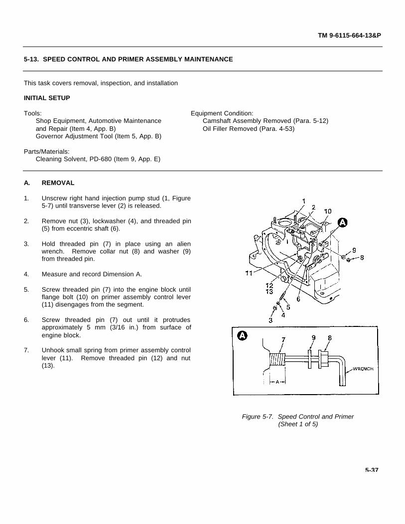
(Figure 5-7 Sheet 1 of 5)(Figure 5-7 Sheet 2 of 5)(Figure 5-7 Sheet 3 of 5)(Figure 5-7 Sheet 4 of 5)(Figure 5-7 Sheet 5 of 5)
TM 9-6115-664-13&P
5-13. SPEED CONTROL AND PRIMER ASSEMBLY MAINTENANCE
This task covers removal, inspection, and installation
INITIAL SETUP
Tools: Equipment Condition:Shop Equipment, Automotive Maintenance Camshaft Assembly Removed (Para. 5-12)and Repair (Item 4, App. B) Oil Filler Removed (Para. 4-53)Governor Adjustment Tool (Item 5, App. B)
Parts/Materials:Cleaning Solvent, PD-680 (Item 9, App. E)
A. REMOVAL
1. Unscrew right hand injection pump stud (1, Figure5-7) until transverse lever (2) is released.
2. Remove nut (3), lockwasher (4), and threaded pin(5) from eccentric shaft (6).
3. Hold threaded pin (7) in place using an alienwrench. Remove collar nut (8) and washer (9)from threaded pin.
4. Measure and record Dimension A.
5. Screw threaded pin (7) into the engine block untilflange bolt (10) on primer assembly control lever(11) disengages from the segment.
6. Screw threaded pin (7) out until it protrudesapproximately 5 mm (3/16 in.) from surface ofengine block.
7. Unhook small spring from primer assembly controllever (11). Remove threaded pin (12) and nut(13).
Figure 5-7. Speed Control and Primer(Sheet 1 of 5)
5-37

TM 9-6115-664-13&P
5-13. SPEED CONTROL AND PRIMER ASSEMBLY MAINTENANCE
8. Using governor adjustment tool, loosen bushing(14, located in speed control lever (15)) by 3revolutions.
9. Remove retaining clip (17) from speed controleccentric shaft (18). Rotate shaft in the stopdirection until return spring (16) is unhooked.Remove shaft as an assembly from engine block(19). Place on a suitable work surface for furthermaintenance.
10. Remove lever (20) and attaching parts on ifdamaged by removing nut (21) and washer (22).
11. Remove bolt (24) and bushing (25) from speedcontrol lever (15). Remove primer assembly (26).
Figure 5-7. Speed Control and Primer(Sheet 2 of 5)
5-38

TM 9-6115-664-13&P
5-13. SPEED CONTROL AND PRIMER ASSEMBLY MAINTENANCE
12. Remove nut (27), washer (28), and accelerationlever (29) from speed control eccentric shaft (18).Remove spacer ring (30).
B. INSPECTION.
WARNING
Cleaning solvent, PD-680, ispotentially dangerous to personneland property. Skin and eyeprotection and good ventilation arerequired. Avoid repeated andprolonged skin contact. Do not usenear open flame or excessive heat.Flash point is 200°° F (93.3°° C).
1. Clean all parts in cleaning solvent and drythoroughly.
2. Visually inspect all parts for signs of broken ordeformed condition. Replace any part that isdamaged or defective.
3. Inspect control levers and control plate for cracks.Replace any part that is cracked.
4. Using a caliper, measure diameter of eccentricshaft at widest point. Diameter shall be 16.000mm minimum (0.630 in.). Replace eccentric shaftif worn beyond limit.
5. Inspect springs for cracks, breaks, or deformation.Replace suspect springs.
C. INSTALLATION.
1. Install spacer ring (30, Figure 5-7) andacceleration lever (29) onto speed controleccentric shaft (18). Secure using nut (27) andwasher (28).
Figure 5-7. Speed Control and Primer(Sheet 3 of 5)
5-39

TM 9-6115-664-13&P
5-13. SPEED CONTROL AND PRIMER ASSEMBLY MAINTENANCE
2. Screw bushing (25) into speed control lever (15)until bushing is flush with rear side of lever. Pushbolt (24) into bushing.
3. Insert the leg of return spring (16) up into hole inspeed control lever (15). Bend leg 15° towardsmiddle of lever to hold in place.
4. Place primer assembly control lever (11) overspeed control lever (15). Hold levers in place inengine block (19).
5. Hold acceleration lever (29) in the stop positionand insert speed control eccentric shaft (18)through bushing in side of engine block (19).
6. Push levers (11, 15) onto eccentric shaft (18).Return spring (16) shall fit into eccentric shaft slotwithout resistance.
7. Turn acceleration lever (29) to full load position.
8. Rotate speed control eccentric shaft (18) whilepulling it slightly out of the engine block bushing.Press speed control control lever (15) in thedirection of the crankcase wall until the pin onlever (15) engages in the fork pin of lever (24).
9. Push eccentric shaft (18) back into bushing andsecure using retaining clip (17).
10. Turn acceleration lever (29) to the full loadposition.
Figure 5-7. Speed Control and Primer(Sheet 4 of 5)
5-40

TM 9-6115-664-13&P
5-13. SPEED CONTROL AND PRIMER ASSEMBLY MAINTENANCE
11. Screw threaded pin (7) into the engine block tomove flange bolt (10) into the bore of the segment.
12. Using an allen wrench, screw threaded pin (7) outof engine block until it reaches position measuredduring REMOVAL, step 4. Hold threaded pin inposition and install collar nut (8) and washer (9).
13. Screw in right hand injection pump stud (1).
14. Set speed control end stop as follows:
a. Move acceleration lever (29) to the stop position.
b. Install threaded pin (5) into eccentric shaft (6).Screw in pin until contact is made with rearcontrol lever.
c. Lock threaded pin (5) in place using nut (3) andwasher (4).
15. Set speed control starting position as follows:
a. Move acceleration lever (29) to the full loadposition. Spread governor weights to themaximum extended position using the governoradjustment tool.
b. Screw bushing (25) into speed control lever (15)until flange bolt fits on governor pin with no play.Tighten bushing an additional 1/2 revolution.Remove tool.
c. Hook small spring onto primer assembly controllever (11).
d. Screw threaded pin (12) in until it contacts pushbolt (24). Secure using nut (13).
20. Install camshaft assembly (Para. 5-12) and oil filler(Para. 4-53).
Figure 5-7. Speed Control and Primer(Sheet 5 of 5)
5-41

TM 9-6115-664-13&P
5-14. FLYWHEEL AND RING GEAR MAINTENANCE
This task covers removal, inspection, and installation
INITIAL SETUP
Tools: Equipment Condition:Shop Equipment, Automotive Maintenance Engine Removed (Para. 5-8)and Repair (Item 4, App. B)
Parts/Materials: Personnel Required:Cleaning Solvent, PD-680 (Item 9, App. E) 2 personnelScrew, M8 x 40 (2 each)Screw, M6 (2 each)
A. REMOVAL
WARNING
Flywheel weighs approximately 80 pounds. Removing nut will allows flywheel tofall off crankshaft. Enlist an assistant when removing to prevent injury anddamage to equipment.
1. Loosen, but do not remove flywheel nut (1, Figure 5-8).
2. Using a flywheel puller, loosen flywheel (2). Remove flywheel nut (1). Rotate flywheel until key on crankshaft is intop position, then remove flywheel.
3. Remove belleville washers (3). Install two M6 screws into holes in angle ring (4). Remove angle ring by pulling onscrews. Remove O-ring seal (5).
4. Remove six nuts (7) and washers (8) that secure bearing cover (9) to mounting studs. Install two M8 x 40 screwsinto holes on opposite sides of bearing cover. Pull screws to separate cover from engine block.
5. Using two screwdrivers, pry oil seal (6) from bearing cover (9). Discard oil seal.
6. Remove and discard cover gasket (10).
B. INSPECTION.
WARNING
Cleaning solvent, PD-680, is potentially dangerous to personnel and property.Skin and eye protection is required. Good ventilation is required. Avoid repeatedand prolonged skin contact. Do not use near open flame or excessive heat. Flashpoint is 200°° F (93.3°° C).
5-42

TM 9-6115-664-13&P
5-14. FLYWHEEL AND RING GEAR MAINTENANCE
Figure 5-8. Flywheel and Ring Gear
1. Clean all parts in cleaning solvent and dry thoroughly. Clean engine block mounting surface using a clean ragdampened with cleaning solvent. Ensure that all cover gasket material is removed from engine block.
2. Inspect flywheel ring gear teeth for damage. Check for chipped, cracked, or missing teeth. Look for signs ofexcessive or unusual wear. Replace flywheel and ring gear as an assembly if damaged.
3. Inspect flywheel crankshaft bore for damage. Check for scoring. Inspect end of crankshaft for damage. Ensurecrankshaft key is properly seated and free from dirt.
4. Conduct visual inspection of crankshaft belleville washers, angle ring, and bearing. Check for damage. Look forscoring or unusual wear.
C. INSTALLATION.
1. Mate new cover gasket (10, Figure 5-8) over mounting studs.
2. Install new oil seal (6), O-ring seal (5), angle ring (4), and belleville washers (3). Install one washer with dish facingout, and the second washer with the dish facing in.
3. Install bearing cover (9) over mounting studs and gently hammer into place using a rubber mallet. Install six nuts(7) and washers (8). Tighten nuts in a criss-cross pattern to ensure even cover installation.
4. Carefully slide flywheel (2) onto crankshaft, ensuring proper alignment of keyway. Install flywheel nut (1) and torqueto 288 to 303 ft-lbs (390 to 410 Nm).
5-43

TM 9-6115-664-13&P
5-15. CYLINDER, PISTON, AND CRANKSHAFT MAINTENANCE
This task covers removal, inspection, repair, and installation
INITIAL SETUP
Tools: Equipment Condition:Shop Equipment, Automotive Maintenance Cylinder Head Removed (Para. 5-9)and Repair (Item 4, App. B)
Parts/Materials:Cleaning Solvent, PD-680 (Item 9, App. E)Lubricating Oil (Item 10, App. E)
A. REMOVAL
1. Manually rotate the flywheel until the piston (5, Figure 5-9) reaches the bottom of its stroke.
2. Remove bottom half of connecting rod (1) from top half (2) by removing screws (3). Remove connecting rod halvesand bearing shells (4) from crankshaft (16).
3. Manually crank the flywheel until piston (5) reaches the top of its stroke. Remove cylinder (6), piston (5), andconnecting rod (2) as one unit. Separate piston from cylinder.
4. Using a drift punch, gently drive piston pin (8) out of piston (5). Remove piston.
5. Remove bushing (10) from top half of connecting rod (2) only if replacement is required.
6. Remove camshaft (Para. 5-12).
7. Remove governor pin (17) and governor (18) from crankshaft (16).
8. If installed, remove flywheel nut (11) from crankshaft (16). Remove belleville washers (12), angle ring (13), and O-ring seal (14). Discard O-ring seal.
9. Using a bearing puller, remove bearing (15). Remove crankshaft (16) from engine block and place on a suitablework surface.
10. Remove flywheel (Para. 5-14).
5-44

(Figure 5-9 Sheet 1 of 5)(Figure 5-9 Sheet 2 of 5)(Figure 5-9 Sheet 3 of 5)(Figure 5-9 Sheet 4 of 5)(Figure 5-9 Sheet 5 of 5)
TM 9-6115-664-13&P
5-15. CYLINDER, PISTON, AND CRANKSHAFT MAINTENANCE
Figure 5-9. Cylinder, Piston, and Crankshaft(Sheet 1 of 5)
5-45

TM 9-6115-664-13&P
5-15. CYLINDER, PISTON, AND CRANKSHAFT MAINTENANCE
B. INSPECTION.
WARNING
Cleaning solvent, PD-680, is potentially dangerous to personnel and property.Skin and eye protection is required. Good ventilation is required. Avoid repeatedand prolonged skin contact. Do not use near open flame or excessive heat. Flashpoint is 200°° F (93.3°° C).
1. Clean all parts in cleaning solvent and dry thoroughly.
2. Visually inspect the crankshaft for scoring on connecting rod journal, bearing journal, and gear journal. Replacecrankshaft if any defects are found.
3. Inspect the crankshaft bearing journal for grooving, indicated by a ridge around the middle of the journal. Replacecrankshaft if grooving is found. Grooving on the journal indicates that the bearing is also worn and must bereplaced.
4. Inspect crankshaft gear for broken, cracked, or chipped teeth. Replace gear, if damaged, using a bearing puller.
5. Inspect bearing for obvious damage. Operate bearing to ensure smooth rotation. Replace bearing if damage issuspected.
6. Measure crankshaft dimensions A, B, C, D, and E.Replace crankshaft if any dimension is beyondlimit.
a. Dimension A = 35.002 to 35.018 mm (1.3790 to1.3797 in.)
b. Dimension B = 55.990 to 56.010 mm (2.2060 to2.2067 in.)
c. Dimension C = 51.940 to 51.960 mm (2.0464 to2.0472 in.)
d. Dimension D = 30.198 to 30.350 mm (1.1898 to1.1958 in.)
e. Dimension E = 45.009 to 45.020 mm (1.7734 to1.7738 in.)
7. Measure the ID of crankshaft gear. ID shall be34.965 to 34.985 mm (1.3776 to 1.3784 in.).Replace crankshaft if beyond limit.
Figure 5-9. Cylinder, Piston, and Crankshaft(Sheet 2 of 5)
5-46

TM 9-6115-664-13&P
5-15. CYLINDER, PISTON, AND CRANKSHAFT MAINTENANCE
8. Inspect piston pin (8) for scoring. Replace pistonpin if scored on outside diameter.
9. Inspect connecting rod for cracks or otherdamage. Replace connecting rod halves as a setif damaged in any way.
10. Inspect inner surface of connecting rod bushing(10) for scoring. Replace bushing if scored (referto REPAIR).
11. Inspect connecting rod bearing halves (4) forscoring. The bearing halves are manufacturedwith a galvanically applied layer on the insidesurface. When the layer is worn through, a shinygold-bronze color will be visible. Replace bearinghalves if layer is worn through.
12. Measure OD of piston pin (8). OD shall be 26.000to 26.996 mm (1.0244 to 1.0636 in.). Replacepiston pin if beyond limit.
13. Measure connecting rod dimensions F and G.Replace connecting rod if any dimension isbeyond limit.
a. Dimension F = 29.000 to 29.013 mm (1.1426 to1.1431 in.)
b. Dimension G = 55.600 to 55.619 mm (2.1906 to2.1913 in.)
14. Measure connecting rod bushing dimensions Hand I. Replace bushing if any dimension isbeyond limit.
a. Dimension H = 29.035 to 29.075 mm (1.1439 to1.1455 in.)
b. Dimension I = 1.483 to 1.495 mm (0.0584 to0.0589 in.)
Figure 5-9. Cylinder, Piston, and Crankshaft(Sheet 3 of 5)
5-47

TM 9-6115-664-13&P
5-15. CYLINDER, PISTON, AND CRANKSHAFT MAINTENANCE
15. Inspect surface of cylinder liner bore for scoring.Replace cylinder if bore is scored.
16. Inspect outside surface of piston walls for scoring.Replace piston if scored.
17. Measure cylinder dimensions L, M, N, O, and P.Replace cylinder if any dimension is beyond limit.
a. Dimension L = 108.990 to 108.995 mm (4.2942to 4.2944 in.)
b. Dimension M = 95.004 to 95.016 mm (3.7431 to3.7436 in.)
c. Dimension N = 115.850 to 115.940 mm (4.5645to 4.5680 in.)
d. Dimension O = 161.500 to 162.500 mm (6.3631to 6.4025 in.)
e. Dimension P = 103.793 to 103.880 mm (4.0894to 4.0929 in.)
18. Measure piston dimensions Q, R. Replace pistonif any dimension is beyond limit.
a. Dimension Q = 95.113 to 95.127 mm (3.7474 to3.7480 in.)
b. Dimension R = 78.650 to 79.350 mm (3.0988 to3.1264 in.)
19. Inspect internal bore of piston (marked S onfigure) for scoring. Inspect external lip (marked T)for damage. Replace piston is damaged in anyway.
20. Using a feeler gage, measure the clearancebetween wall of piston groove and top piston ring(compression). Replace ring set (see REPAIR) ifclearance is greater than 0.037 mm (0.0015 in.).
Figure 5-9. Cylinder, Piston, and Crankshaft(Sheet 4 of 5)
5-48

TM 9-6115-664-13&P
5-15. CYLINDER, PISTON, AND CRANKSHAFT MAINTENANCE
21. Measure clearance between wall of piston groove and middle piston ring. Replace ring set if clearance is greaterthan 0.031 mm (0.0012 in.).
22. Measure clearance between wall of piston groove and bottom piston ring (oil control). Replace ring set if clearanceis greater than 0.031 mm (0.0012 in.).
C. REPAIR.
1. Replace connecting rod bushing (10) as follows:
a. Using an arbor press, press bushing from connecting rod.
b. Ensure that the bore of connecting rod and replacement bushing are clean.
c. Align replacement bushing with rod bore, ensuring that the oil hole in the bushing is in line with the oil passage inthe top of the connecting rod. Using an arbor press, install the bushing until it is flush with the face of theconnecting rod.
2. Replace piston ring set as follows:
a. Using a piston ring expander, remove and discard the piston rings.
NOTE
Ensure that piston rings are installed with markings facing top of piston.
b. Using a piston ring expander, install the oil control ring in the bottom groove of the piston.
c. Install the middle ring in the middle groove of the piston. Install the compression ring in the top groove of thepiston.
d. Stagger the position of the rings so that the ring end gaps are 120 degrees apart.
5-49

TM 9-6115-664-13&P
5-15. CYLINDER, PISTON, AND CRANKSHAFT MAINTENANCE
D. INSTALLATION.
1. Carefully install crankshaft (16, Figure 5-9) into engine block, inserting crankshaft end journal into bearing (15).Coat the bearing race on crankshaft with lubricating oil.
2. Coat new O-ring seal (14) and angle ring (13) with lubricating oil and install onto crankshaft (16). Install onebelleville washer (12) with dish facing out, and the second belleville washer with dish facing in.
3. Compress piston rings (9) with a ring compressor. Position piston (5) with ring compressor onto cylinder (6) andpush piston into cylinder.
4. Remove ring compressor. Adjust position of piston (5) in cylinder (6) so the piston pin bore is fully exposed belowthe cylinder liner.
5. Install assembled piston (5) and cylinder (6) over mounting studs. Engage the top of connecting rod (2) with piston.
6. Install piston pin (8) in piston (5) and connecting rod (2) bore. Tap into place until the piston pin is centered. Installnew retaining rings (24).
7. Install flywheel (Para. 5-14).
8. Assemble piston (5), cylinder (6), and connecting rod (2).
9. Locate one half of connecting rod bearing (4) into top part of connecting rod (2). Align the lip of the bearing half withthe groove in the connecting rod. Slide the bearing half into the connecting rod while depressing the center of thebearing half to conform it to the contour of the rod. Seat the bearing half with both ends flush with the flanges of therod.
10. Turn crankshaft to top dead center (TDC) position. Install piston (5), cylinder (6), and connecting rod (2) whileturning crankshaft to bottom dead center (BDC) position.
11. Install the second half of connecting rod bearing (4) into bottom part of connecting rod (1) in the same manner asstep 8. Apply a coat of lubricating oil to both bearing halves after they are installed.
12. Mate bottom part of connecting rod (1) to crankshaft journal. Secure connecting rod using two screws (3). Torquescrews to 43 to 46 ft-lbs (58 to 62 Nm).
13. Install camshaft (Para. 5-12) and flywheel (Para. 5-14).
14. Install cylinder head (Para. 5-9).
5-50

TM 9-6115-664-13&P
5-15. CYLINDER, PISTON, AND CRANKSHAFT MAINTENANCE
Figure 5-9. Cylinder, Piston, and Crankshaft(Sheet 5 of 5)
5-51

TM 9-6115-664-13&P
5-16. ALTERNATOR MAINTENANCE
This task covers testing, removal, inspection, and installation
INITIAL SETUP
Tools: Equipment Condition:Shop Equipment, Automotive Maintenance APU Shut Downand Repair (Item 4, App. B)Alternator Tool / Test Set (Item 7, App. B)
A. TESTING. The following tests shall be conducted when the APU fails to generate voltage or voltage generated isbelow rated level. These tests are designed to isolate the cause of the fault.
1. Battery power must be supplied to the alternator's B+ terminal to perform these tests. If contactor (main powerrelay) will not, or cannot, engage, the contactor must be bypassed out of the circuit to complete the tests. Bypassthe contactor, if required, as follows:
a. Disconnect power from the APU by unplugging NATO connector.
b. Open top rear cover on APU enclosure by turning latches. Remove fuel module cover.
c. Look into fuel module and locate B+ and B- terminals on rear of NATO connector. B+ terminal is insulated. B-terminal is not insulated.
d. Locate ALTERNATOR POSITIVE terminal on outside panel of fuel module.
e. Connect test cable #1 (red wire cable) from NATO connector B+ terminal to ALTERNATOR POSITIVE terminal.
f. Reconnect NATO connector to APU. Contactor is now bypassed.
2. Disconnect APU wiring harness from the round alternator control receptacle (Figure 5-10). This disconnectsalternator from APU control panel.
3. Connect plug end of test cable #2 (brown wire cable) to the round alternator control receptacle. Connect alligatorclip end of cable #2 to the alternator's B+ output stud. Completing this connection will energize the regulator,turning on the alternator.
NOTE
Test cable #2 has pins C and D connected for use with the N3120 regulator. Pins Cand D are not used on the N3129 regulator and have no effect on the circuit.
4. Disconnect the regulator electrical connector from regulator.
5-52

(Figure 5-10 Sheet 1 of 2)(Figure 5-10 Sheet 2 of 2)
TM 9-6115-664-13&P
5-16. ALTERNATOR MAINTENANCE
VOLTAGE REGULATOR PINFUNCTIONSPIN A GROUNDPIN B ENERGIZEPIN C FIELD-PIN D NOT USEDPIN E B+
Figure 5-10. Alternator(Sheet 1 of 2)
5-53

TM 9-6115-664-13&P
5-16. ALTERNATOR MAINTENANCE
5. Test for battery voltage as follows. Replace alternator if battery voltage is not present:
a. Connect multimeter red lead to regulator connector pin E. Connect multimeter black lead to alternator groundbolt. Battery voltage shall be present.
b. Connect multimeter red lead to the alternator B+ output stud. Connect multimeter black lead to regulatorconnector pin A. Battery voltage shall be present.
c. Connect multimeter red lead to regulator connector pin B. Connect multimeter black lead to alternator groundbolt. Battery voltage shall be present.
6. Connect test cable #3 (white cable with regulator connectors and alligator clip) between regulator connector andregulator.
WARNING
Do not ground alligator clip. Injury to personnel and damage to equipment couldresult.
7. Connect multimeter red lead to test cable #3 alligator clip. Connect multimeter black lead to alternator ground bolt.Voltage reading shall be less than 1.0 volt. If voltage is greater than 1.0 volt, regulator is defective and must bereplaced. Leave multimeter connected.
8. Disconnect test cable #2 alligator clip from the alternator B+ output stud. Multimeter will now read battery voltage.If voltage reading at pin C is below battery voltage, regulator is defective and must be replaced.
9. If additional testing is required, proceed as follows:
WARNING
Use caution when testing alternator magnetic pull. There will be a spark whenalligator clip contacts ground bolt. Steel tool will "jump" from hand and snapagainst alternator. Do not hold hand between tool and alternator.
a. With test cable #3 still connected between regulator connector and regulator, connect test cable #3 alligator clip toalternator ground bolt. There will be a large spark at the point of connection, indicating that the field coil isconducting.
b. Place a steel tool next to the alternator fan hub (a thin piece of steel will work as well). If the tool snaps againstthe hub, the alternator coil is good and will produce electricity. Replace the regulator.
c. If tool is not attracted to alternator hub, the field coil is defective. Replace the alternator.
10. Disconnect all test cables. Install fuel module cover and close top rear lid.
5-54

TM 9-6115-664-13&P
5-16. ALTERNATOR MAINTENANCE
B. REMOVAL.
NOTE
Note location of silicon adhesive and silicon sponge to aid in reassembly.
1. Remove engine (Para. 5-8).
2. Remove flywheel shroud (1, Figure 5-10) from flywheel housing (2) by removing two screws (3), lockwashers (4),and washers (5).
3. Remove screw (7), washer (8), and lockwasher (9) that secure voltage regulator (6) to alternator.
4. Remove alternator fan shroud (10) from mounting blocks (13) by removing six screws (11), washers (12), and nuts(13).
5. Remove screw (14), washers (15, 16), and locknut (17) from lower mounting block (13). Remove mounting blocksfrom alternator fan by removing screws (18), washers (19), and nuts (20).
6. Remove metal flex coupling (21) from alternator shaft (22) by removing nut (23) and washer (24). Loosen couplingsetscrew. Remove coupling from alternator shaft using a puller.
7. Remove flywheel housing (2) from alternator by removing four screws (25), washers (26), and lockwashers (27).
8. Remove four sleeves (28), screws (29), and washers (30) from flex coupling (21) only if damaged.
C. INSPECTION.
1. Inspect alternator for signs of damage. Inspect for corrosion and evidence of electrical short. Inspect metalcomponents for cracks and dents.
2. Inspect electrical wiring for cuts, tears, kinks, or damage. Inspect electrical connectors and receptacle for bent,broken, or missing contactors.
3. Inspect metal flex coupling for signs of wear or stress.
5-55

TM 9-6115-664-13&P
5-16. ALTERNATOR MAINTENANCE
Figure 5-10. Alternator(Sheet 2 of 2)
5-56

TM 9-6115-664-13&P
5-16. ALTERNATOR MAINTENANCE
D. INSTALLATION.
1. Apply silicon adhesive and foam insulating tape in accordance with notes made during removal.
2. Install four sleeves (28, Figure 5-10), screws (29), and washers (30) onto metal flex coupling (21).
3. Mate flywheel housing (2) to alternator and secure using four screws (25), washers (26), and lockwashers (27).
4. Install flex coupling (21) onto alternator shaft (22) so that keyway is aligned over key. Secure by tightening couplingsetscrew. Install nut (23) and washer (24).
5. Install mounting blocks (13) over alternator fan and secure using screws (18), washers (19), and nuts (20). Installscrew (14), washers (15, 16), and locknut (17) into lower mounting bracket.
6. Install voltage regulator (6) onto alternator using screw (7), washer (8), and lockwasher (9).
7. Fit alternator fan shroud (10) onto mounting blocks (13) and secure using six screws (11), washers (12), and nuts(13).
8. Fit flywheel shroud (1) onto alternator and mate to flywheel housing (2). Secure using two screws (3), lockwashers(4), and washers (5).
9. Install engine (Para. 5-8).
5-57

TM 9-6115-664-13&P
5-17. OIL COOLER MAINTENANCE
This task covers removal, inspection, and installation
INITIAL SETUP
Tools: Equipment Condition:Shop Equipment, Automotive Maintenance Engine/Alternator Removed (Para. 5-7)and Repair (Item 4, App. B) Oil Cooler Hoses Disconnected (Para. 4-38)
A. REMOVAL.
1. If replacement is required, remove sound-proofing material (1, Figure 5-11) from inside of enclosure by removingdome washers (2).
2. Remove engine mount (Para. 5-7).
3. Remove oil cooler guard (3) from enclosure by removing eight screws (4), washers (5), and four locknuts (6).
4. Remove oil cooler (7) from enclosure by removing six screws (12) and lockwashers (13) securing front portion ofmounting block (11).
5. If replacement is required, remove eight split bushings (14) from oil cooler (7).
6. If replacement is required, remove rear portion of mounting blocks (11) from enclosure by removing four screws (8),lockwashers (9), and washers (10).
B. INSPECTION..
1. Inspect oil cooler for obvious damage. Inspect for evidence of leakage or corrosion. Inspect oil cooler fins fordamage and straighten as required.
2. Inspect edge seal on oil cooler guard for damage. Remove and replace as required.
3. Inspect rubber grommets on oil cooler cover for damage. Replace as required.
5-58

TM 9-6115-664-13&P
5-17. OIL COOLER MAINTENANCE
C. INSTALLATION.
1. Install eight split bushings (14, Figure 5-11) ontooil cooler (7) using silicon.
2. Mate rear portion of two-piece cooler mountingblocks (11) to enclosure and secure using fourscrews (8), lockwashers (9), and washers (10).
3. Mate oil cooler (7) to rear portion of block (11).Install front portion of block using six screws (12)and lockwashers (13).
4. Install oil cooler guard (3) using eight screws (4),washers (5), and nuts (6).
5. Install soundproofing material (1) and secure usingdome washers (2).
6. Install engine/alternator assembly and enginemounts (Para. 5-7).
7. Connect oil cooler hoses (Para. 4-38).
Figure 5-11. Oil Cooler
5-59/(5-60 blank)

TM 9-6115-664-13&P
APPENDIX A
REFERENCES
A-1. Scope.
This appendix lists all forms, field manuals, and technical manuals referenced in this manual or used in conjunctionwith the APU.
FormsRecommended Changes to Publications DA Form 2028Recommended Changes to Equipment
Technical Manuals DA Form 2028-2Equipment Inspection and Maintenance Worksheet DA Form 2404Product Quality Deficiency Report DA Form 368
Field ManualsFirst Aid for Soldiers FM 21-11
Painting RequirementsColor, Marking, and Preparation of Equipment
for Shipment AR 740-1Color and Marking of Army Material AR 746-5
Technical BulletinsNoise and Conservation of Hearing TB MED 251Hand Portable Fire Extinguishers Approved
for Army Use TB 5-4200-200-10Specification List of Standard Liquid Fuels,
Lubricants, Preservatives, and RelatedProducts Authorized for Use by US Army TB 703-1
Technical ManualsThe Army Maintenance Management System (TAMMS) TM 738-750Administrative Storage of Equipment TM 740-90-1Procedures for Destruction of Equipment to Prevent Enemy Use TM 750-244-3
A-1/(A-2 blank)

TM 9-6115-664-13&P
APPENDIX B
MAINTENANCE ALLOCATION CHART (MAC)
Section I. INTRODUCTION
B-1. General.
a. This section provides a general explanation of all maintenance and repair functions authorized at variousmaintenance categories.
b. The Maintenance Allocation Chart (MAC) in Section II designates overall authority and responsibility for theperformance of maintenance functions on the identified end item or component. The application of the maintenancefunctions to the end item or component will be consistent with the capacities and capabilities of the designatedmaintenance levels, which are shown in the MAC in column (4) as:
Unit - includes two subcolumns, C (operator/crew) and O (unit) maintenance.
Direct Support - includes an F subcolumn.
General Support - includes an H subcolumn.
Depot - includes a D subcolumn.
c. Section III lists the tools and test equipment (both special tools and common tool sets) required for eachmaintenance function as referenced from Section II.
d. Section IV contains supplemental instructions and explanatory notes for a particular maintenance function.
B-2. Maintenance Functions. Maintenance functions are limited to and defined as follows:
a. Inspect. To determine the serviceability of an item by comparing its physical, mechanical, and/or electricalcharacteristics with established standards through examination (e.g., by sight, sound, or feel).
b. Test. To verify serviceability by measuring the mechanical, pneumatic, hydraulic, or electrical characteristics ofan item and comparing those characteristics with prescribed standards.
c. Service. Operations required periodically to keep an item in proper operating condition; e.g., to clean (includesdecontaminate, when required), to preserve, to drain, to paint, or to replenish fuel, lubricants, chemical fluids, or gases.
d. Adjust. To maintain or regulate, within prescribed limits, by bringing into proper position, or by setting theoperating characteristics to specified parameters.
e. Align. To adjust specified variable elements of an item to bring about optimum or desired performance.
B-1

TM 9-6115-664-13&P
f. Calibrate. To determine and cause corrections to be made or to be adjusted on instruments or test, measuring,and diagnostic equipment used in precision measurement. Consists of comparisons of two instruments, one of which is acertified standard of known accuracy, to detect and adjust any discrepancy in the accuracy of the instrument beingcompared.
g. Remove/Install. To remove and install the same item when required to perform service or other maintenancefunctions. Install may be the act of emplacing, seating, or fixing into position a spare, repair part, or module (componentor assembly) in a manner to allow the proper functioning of an equipment or system.
h. Replace. To remove an unserviceable item and install a serviceable counterpart in its place. "Replace" isauthorized by the MAC and assigned maintenance level is shown as the 3rd position code of the SMR code.
i. Repair. The application of maintenance services(1) including fault location/troubleshooting(2),removal/installation, and disassembly/assembly(3) procedures, and maintenance actions(4) to identify troubles andrestore serviceability to an item by correcting specific damage, fault, malfunction, or failure in a parts, subassembly,module (component or assembly), end item, or system.
j. Overhaul. That maintenance effort (service/action) prescribed to restore and item to a completelyserviceable/operational condition as required by maintenance standards in appropriate technical publications (i.e.,DMWR). Overhaul is normally the highest degree of maintenance performed by the Army. Overhaul does not normallyreturn an item to Like new condition.
k. Rebuild. Consists of those services/actions necessary for the restoration of unserviceable equipment to a likenew condition in accordance with original manufacturing standards. Rebuild is the highest degree of materielmaintenance applied to Army equipment. The rebuild operation includes the act of returning to zero those agemeasurements (e.g., hours/miles) considered in classifying Army equipment/components.
(1) Services - Inspect, test, service, adjust, align, calibrate, and/or replace.
(2) Fault location/troubleshooting - The process of investigating and detecting the cause of equipment malfunctioning;the act of isolating a fault within a system or unit under test (UUT).
(3) Disassembly/assembly - The step-by-step breakdown (taking apart) of a spare/functional group coded item to thelevel of its least component, that is assigned an SMR code for the level of maintenance under consideration (i.e.,identified as maintenance significant).
(4) Actions - Welding, grinding, riveting, straightening, facing, machining, and/or resurfacing.
B-2

TM 9-6115-664-13&P
B-3. Explanation of Columns in the MAC, Section II.
a. Column 1, Group Number. Column 1 lists functional group code numbers, the purpose of which is to identifymaintenance significant components, assemblies, subassemblies, and modules with the next higher assembly.
b. Column 2, Component/Assembly. Column 2 contains the item names of components, assemblies,subassemblies, and modules for which maintenance is authorized.
c. Column 3, Maintenance Function. Column 3 lists the functions to be performed on the item listed in Column 2.(For detailed explanation of these functions, see paragraph B-2).
d. Column 4, Maintenance Level. Column 4 specifies each level of maintenance authorized to perform eachfunction listed in Column 3, by indicating work time required (expressed as man-hours in whole hours or decimals) in theappropriate subcolumn. This work-time figure represents the active time required to perform that maintenance function atthe indicated level of maintenance. If the number or complexity of the tasks within the listed maintenance function vary atdifferent maintenance levels, appropriate work-time figures are shown for each level. The work-time figure represents theaverage time required to restore an item (assembly, subassembly, component, module, end item, or system) to aserviceable condition under typical field operating conditions. This time includes preparation time (including anynecessary disassembly/assembly time), troubleshooting/fault location time, and quality assurance time in addition to thetime required to perform the specific tasks identified for the maintenance functions authorized in the maintenanceallocation chart. the symbol designations for the various maintenance levels are as follows:
C Operator or crew maintenanceO Unit maintenanceF Direct support maintenanceL Specialized Repair Activity (SRA) (5)H General support maintenanceD Depot maintenance
e. Column 5, Tools and Test Equipment Reference Code. Column 5 specifies, by code, the common tool sets(not individual tools), common TMDE, and special tools, special TMDE, and special support equipment required toperform the designated function. Codes are keyed to tools and test equipment in Section III.
f. Column 6, Remarks. When applicable, this column contains a letter code, in alphabetical order, which is keyedto the remarks contained in Section IV.
(5) This maintenance level is not included in Section II, Column 4 of the MAC. Functions to this level of maintenance areidentified by a work-time figure in the "H" column in Section II, Column 4, and an associated reference code is used in theRemarks column. This code is keyed to Section IV, remarks, and the SRA complete repair application is explained there.
B-3

TM 9-6115-664-13&P
B-4. Explanation of Columns in Tool and Test Equipment Requirements, Section III.
a. Column 1, Reference Code. The tool and test equipment reference code correlates with a code used in theMAC, Section II, Column 5.
b. Column 2, Maintenance Level. The lowest level of maintenance authorized to use the tool or test equipment.
c. Column 3, Nomenclature. Name or identification of the tool or test equipment.
d. Column 4, National Stock Number. The National Stock Number of the tool or test equipment.
e. Column 5, Tool Number. The manufacturer's part number, model number, or type number.
B-5. Explanation of Columns in Remarks, Section IV.
a. Column 1, Remarks Code. The code recorded in Column 6, Section II.
b. Column 2, Remarks. This column lists information pertinent to the maintenance function being performed asindicated in the MAC, Section II.
B-4

(1) (2) (3) (4)MAINTENANCE LEVEL (5) (6)
GroupNumber Component/Assembly
MaintenanceFunction
Oper UnitDirect
SupportF
GeneralSupport
HDepot
D
Tools andEquipmentRef Code
RemarksCode
TM 9-6115-664-13&PSection II. MAINTENANCE ALLOCATION CHART
FOR MEP-952
00 MEP-952B INSPECT 0.1 0.1 0.4 AAUXILIARY POWER SERVICE 0.1 0.3 1 A, DUNIT TEST 0.5 4
REPAIR 0.2 0.5 1.8 1, 4 - 6 G
01 NOSEPIECE ASSY INSPECT 0.1 0.1 AREPLACE 0.3 1REPAIR 0.4 1
02 COVER ASSY INSPECT 0.1 0.1 AREPLACE 0.4 1REPAIR 0.5 1
0201 COVER ASSY INSPECT 0.1 0.1 A(FRONT) REPLACE 0.4 1
REPAIR 0.3 1
0202 COVER ASSY INSPECT 0.1 0.1 A(REAR) REPLACE 0.4 1
REPAIR 0.3 1
03 CASE ASSY (APU INSPECT 0.1 0.1 AENCLOSURE) REPLACE 0.7 1
REPAIR 0.7 1
0301 OIL COOLER ASSY INSPECT 0.1 AREPLACE 0.4 1REPAIR 0.4 1
04 CONTROL PANEL INSPECT 0.1 0.1 AASSY, LOCAL TEST 0.2 1 A
REPLACE 0.4 1REPAIR 0.5 1 E
0401 SWITCH ASSY, TEST 0.2 1LOCAL CONTROL REPLACE 0.4 1PANEL
B-5

GroupNumber Component/Assembly
MaintenanceFunction
Oper UnitDirect
SupportF
GeneralSupport
HDepot
D
Tools andEquipmentRef Code
RemarksCode
TM 9-6115-664-13&P
05 REMOTE CONTROL INSPECT 0.1 0.1 AASSY TEST 0.1 1 A, B,
REPLACE 0.2REPAIR 0.5 1, 2 E
0501 SWITCH ASSY, TEST 0.2 1REMOTE CONTROL REPLACE 0.4 1ASSY
06 MODULE ASSY, INSPECT 0.1 0.1 AFUEL SERVICE 0.1 0.3 A
REPAIR 0.8 1 EREPLACE 0.4 1
0601 PUMP ASSY, FUEL INSPECT 0.1 0.1 AREPAIR 0.2 1 EREPLACE 0.4 1
0602 HOUSING ASSY, INSPECT 0.1FUEL FLOAT VALVE TEST 0.1
REPAIR 0.6 1 EREPLACE 0.6 1
07 ENGINE / INSPECT 0.1 0.1 0.4 AALTERNATOR SERVICE 0.1 0.3 1 AASSY TEST 0.5 4
REPAIR 0.2 1.3 1.8 1,4 - 6 GREPLACE 0.8 4, 5
0701 SHROUD ASSY INSPECT 0.1 AREPAIR 0.5 1 EREPLACE 0.8 1
0702 ENGINE ASSY INSPECT 0.2REPAIR 0.5 0.5 1, 4 EREPLACE 0.8 4, 5
070201 ENGINE, DIESEL INSPECT 0.1 0.1 0.4 4 ASERVICE 0.1 0.3 AADJUST 0.4 1 ATEST 0.5 4REPAIR 1.3 1.8 4 - 6REPLACE 0.8 4, 5
070201 CYLINDER HEAD INSPECT 0.2 401 ASSY REPLACE 1.3 4
REPAIR 1.0 4 E
B-6

GroupNumber Component/Assembly
MaintenanceFunction
Oper UnitDirect
SupportF
GeneralSupport
HDepot
D
Tools andEquipmentRef Code
RemarksCode
TM 9-6115-664-13&P
070201 PISTON INSPECT 0.4 402 REPLACE 1.5 4
REPAIR 1.3 4 E
070201 CONNECTING ROD INSPECT 0.4 403 REPLACE 1.5 4
070201 CRANKSHAFT INSPECT 0.4 404 ASSY REPLACE 1.5 4
REPAIR 0.8 4 E
070202 EXHAUST PIPE INSPECT 0.1 AASSY REPLACE 0.6 1
REPAIR 0.4 1 E
0703 ALTERNATOR INSPECT 0.1 0.1 4 AASSY ADJUST 0.3 4
TEST 0.5 4REPAIR 1.0 4 EREPLACE 0.8 4, 5
08 EXHAUST ASSY, REPLACE 1.0 4INTERNAL REPAIR 0.7 4 E
B-7

TM 9-6115-664-13&P
Section III. TOOLS AND TEST EQUIPMENTFOR MEP-952B
Tool or TestEquipment Maintenance NationalRef Code Level Nomenclature Stock Number Tool Number
1 O SHOP EQUIPMENT, AUTOMOTIVE 4910-00-754-0654 SC4910-95-CL-MAINTENANCE AND REPAIR, ORG A74LEVEL COMMON NO. 1
2 O TOOL KIT, GENERAL MECHANIC'S 5180-00-177-7033 SC5180-90-CL-AUTOMOTIVE N26
3 F TOOL KIT, GENERAL MECHANIC'S 5180-00-699-5273 SC5180-90-CL-N05
4 F SHOP EQUIPMENT, AUTOMOTIVE 4910-00-754-0705 SC4910-95-CL-MAINTENANCE AND REPAIR: A31FIELD MAINTENANCE, BASIC,LESS POWER
5 F HOIST, 600 LB CAPACITY
6 F GOVERNOR ADJUSTMENT TOOL 28099002
7 F TOOL / TEST SET 28099001
Section IV. REMARKSFOR MEP-952B
RemarksCode Remarks
A PREVENTIVE MAINTENANCE CHECKS AND SERVICES (PMCS)
B TEST BY DEPRESSING LAMP TEST SWITCH TO TEST LED INDICATORS
C CONTINUITY CHECK USING MULTIMETER
D SERVICE IN ACCORDANCE WITH LUBRICATION ORDER, APPENDIX F
E REPAIR IS LIMITED TO REPLACEMENT OF DAMAGED PARTS
F TEST BY DEPRESSING SWITCH AND OBSERVING SHUTDOWN
G REPAIR AT OPERATOR LEVEL IS LIMITED TO REMOVAL AND REPLACEMENT OF AIRFILTER AND DRAINING OF WATER FROM FUEL WATER SEPARATOR.
B-8
TM 9-6115-664-13&P
APPENDIX C
COMPONENTS OF END ITEM (COEI) AND BASIC ISSUE ITEMS (BII) LIST
Section I. INTRODUCTION
C-1. Scope.
This appendix list components of end item and basic issue items for the APU to help you inventory the items for safeand efficient operation of the equipment.
C-2. General.
The Components of End Item (COEI) and Basic Issue Items (BI) lists are divided into the following sections:
a. Section II, Components of End Item. This listing is for information purposes only, and is not authority torequisition replacements. These items are part of the APU. As part of the end item, these items must be with the enditem whenever it is issued or transferred between property accounts. Items of COEI are removed and separatelypackaged for transportation or shipment only when necessary. Illustrations are furnished to help you find and identify theitems.
b. Section III, Basic Issue Items. These essential items are required to place the APU in operation, operate it, andto do emergency repairs. Although shipped separately packaged, BE must be with the APU during operation and when itis transferred between property accounts. This list is your authority to request/requisition them for replacement based onauthorization of the end item by the TOE/MTOE. Illustrations are furnished to help you find and identify the items.
C-3. Explanation of Columns.
a. Column 1, Illus Number, gives you the number of the item illustrated.
b. Column 2, National Stock Number, identifies the stock number of the item to be used for requisitioningpurposes.
c. Column 3, Description and Usable On Code , identifies the Federal item name (in all capital letters) followed bya minimum description when needed. The last line below the description is the Commercial and Government Entity Code(CAGEC) (in parentheses) and the part number.
d. Column 4, U/I (Unit of Issue), indicates how the item is issued for the National Stock Number shown in Column(2).
e. Column 5, Qty Rqd, indicates the quantity required.
C-1

TM 9-6115-664-13&P
Section II. COMPONENTS OF END ITEM
(1) (2) (3) (5)Illus National Stock Description (4) Qty
Number Number CAGEC and Part Number U/M Rqr
TO BE SUPPLIED BY CECOM PER ACTION ITEM
Section III. BASIC ISSUE ITEMS
(1) (2) (3) (5)Illus National Stock Description (4) Qty
Number Number CEGEC and Part Number U/M Rqr
1 To Be Assigned TECHNICAL MANUAL, TM 9-6115-664-13&P EA 1
C-2

TM 9-6115-664-13&P
APPENDIX D
ADDITIONAL AUTHORIZATION LIST
Section I. INTRODUCTION
D-1. Scope.
This appendix lists additional items that you are authorized for the support of the APU.
D-2. General.
This list identifies items that do not accompany the APU and that do not have to be turned in with it. These items areall authorized by CTA, MTOR, TDA, or JTA.
D-3. Explanation of Listing.
National Stock Numbers, descriptions, and quantities are provided to help identify and request the additional itemsrequired to support the APU. The items are listed in alphabetical sequence by item name under the type of document (ie,CTA, MTOR, TDA, or JTA) which authorizes the item(s).
Section II. ADDITIONAL AUTHORIZATION LIST
(2) (3) (4) (5)National Stock Description Usable Qty
Number CEGEC and Part Number On Code U/I Reqd
NOT APPLICABLE
D-1/(D-2 blank)

TM 9-6115-664-13&P
APPENDIX E
EXPENDABLE AND DURABLE ITEMS LIST
Section I. INTRODUCTION
E-1. Scope.
This appendix lists expendable and durable items that you will need to operate and maintain the APU. This listing isfor information only and is not authority to requisition the listed items. These items are authorized to you by CTA 50-790,Expendable/Durable Items (except medical, class V repair parts, and heraldic items), or CTA 8-100, Army MedicalDepartment Expendable/Durable Items.
E-2. Explanation of Columns.
a. Column 1, Item Number. This number is assigned to the entry in the listing and is referenced in the narrativeinstructions to identify the item (e.g., Cleaning Compound (Item 5, App. E) ).
b. Column 2, Level. This column identifies the lowest level of maintenance that requires the item.
c. Column 3, National Stock Number. This is the national stock number assigned to the item which you can useto requisition it.
d. Column 4, Item Name, Description, CAGEC, Part Number. This provides the other information you need toidentify the item.
e. Column 5, UM. This code shows the physical measurement or count of an item, such as gallon, dozen, pound,or gross.
E-1

TM 9-6115-664-13&P
Section II. EXPENDABLE/DURABLE SUPPLIES ANDREQUIREMENTS LIST
(1) (2) (3) (4) (5)Item National Stock Item Name, Description
Number Level Number CAGEC, Part Number U/M
1 O, F ADHESIVE, LOCTITE (0A083) P/N 242 OZ
2 O ADHESIVE, SILICON (81349) P/N MIL-A-46106 OZ
3 O, F COMPOUND, ANTI-SEIZE (81349) P/N M[L-A-907
4 O, F SEALANT, THREAD (62377) P/N 82480
5 F GREASE
6 O POLYURETHANE COATING, ENAMEL, COLOR GLGREEN, PER FED-STD-595 (81349)P/N TT-E-527 / MIL-C-46168
7 O, F RAG, SHOP, CLEANING EA
8 O TAPE, VERY HIGH BON (VHB) (U6293) P/N 4950 RL
9 O, F 6580-00-285-8011 SOLVENT, CLEANING, DRY (81349) P/N PD-680, QTTYPE II OR III
10 C, O, F 9150-00-186-6668 OIL, LUBRICATING, ENGINE (81349) P/N MIL-L-2104 QT
11 C, O, F OIL, LUBRICATING, ENGINE, ARCTIC (81349) QTP/N MIL-L-46176
12 O, F ADHESIVE, CONTACT, SPRAY-ON (81349) TBDP/N MMM-A-130
13 O WIRE, SAFETY RL
E-2

TM 9-6115-664-13&P
APPENDIX F
LUBRICATION INSTRUCTIONS
F-1. Scope.
This appendix provides instructions for lubricating and servicing the APU.
F-2. General.
a. Intervals (on-condition or hard time) and the related man-hour times are based on normal operation. The man-hour time specified is the time you need to do all the services prescribed for a particular interval. Change the hard timeinterval if your lubricants are contaminated or if you are operating the equipment under adverse operating conditions,including longer-than-usual operating hours. The hard time interval may be extended during periods of low activity. Ifextended, adequate preservation precautions must be taken.
b. Lubrication points are indicated by arrow shafts on the equipment.
c. The lowest level of maintenance authorized to lubricate a point is Unit Maintenance (C).
F-3. Oil Servicing Procedures.
a. Unlock lid latches and open APU front lid.
b. Remove engine oil dipstick. Wipe clean and reinsert into engine. Remove dipstick and check oil level.
c. High mark on dipstick indicates "full" condition. Oil level on dipstick must fall between high and low marks.
CAUTION
Always wipe clean oil filler components before starting your lube service. Neveruse the wrong type or grade of oil. Never use too much oil, as overfilling willcause spillage and harm engine components.
d. If oil level is low, remove oil filler cap. Fill engine with up to 2.5 quarts of engine lubricating oil as specified. Pouroil slowly to prevent overflow.
e. Using engine oil dipstick, check for proper oil level.
f. Install oil filler cap. Close front lid and lock using lid latches.
F-1

TM 9-6115-664-13&P
TOTAL TASK-HR
INTERVAL TASK-HR
10 hours 0.25
LUBRICANT INTERVAL
Dipstick(Check oil level)(C) (See note 4)
MIL-L-2104/MIL-L-46167
Engine OilFill Tube(C)
KEY
Temperature Range Lubricant Mil. Symbol Capacity Interval Man-hourSpecification
0 F to +120 F (-18 to +49 C) MIL-L-2104, 15W40 2.7 QTS 10 hours .10(2.6 LTRS)
-25 F to +15 F (-32 to -9.5 C) MIL-L-46167, 5W30 2.7 QTS 10 hours .10(2.6 LTRS)
Copy of these lubrication instructions will remain with the equipment at all times; instructions containedherein are mandatory.
F-2

TM 9-6115-664-13&P
APPENDIX G
REPAIR PARTS AND SPECIAL TOOLS LIST
Section I. Introduction
G-1. Scope.
This appendix lists and authorizes spares and repair parts; special tools; special test, measurement, and diagnosticequipment (TMDE); and other special support equipment required for the performance of unit, direct support, and generalsupport maintenance of the 5KW APU. It authorizes the requisitioning, issue, and disposition of spares, repair parts andspecial tools as indicated by the source, maintenance, and recoverability (SMR) codes.
G-2. General.
In addition to Section I, Introduction, this Repair Parts and Special Tools List is divided into the following sections:
a. Section II. Repair Parts List. A list of spares and repair parts authorized by this RPSTL for use in theperformance of maintenance. This list also includes parts which must be removed for replacement of the authorizedparts. Parts lists are composed of functional groups in ascending alphanumeric sequence, with the parts in each grouplisted in ascending item number sequence. Figure numbers are listed directly beneath the group header. Bulk materialsare listed in item name sequence. Repair part kits are listed separately in their own functional group within Section II.Repair parts for reparable special tools are also listed in this section. Items listed are shown on the associated illustration.
b. Section III. Special Tools List. Not applicable. A list of special tools, special TMDE, and other special supportequipment authorized by this RPSTL as indicated by Basis of Issue (BOI) information in (column (5) ) for the performanceof maintenance.
c. Section IV Cross-Reference Indexes. A List, in National item identification number (NIIN) sequence, of allNational stock numbered items appearing in the listing, followed by a list in alphanumeric sequence of all part numbersappearing in the listings. National stock numbers and part numbers are cross-referenced to each illustration figure anditem number appearance. The figure number and item number index lists figure and item numbers in numeric sequenceand cross-references National stock number, Commercial and Government Entity Code, and part numbers.
G-3. Explanation of Columns (Sections II and III).
a. Item No. (Column (1)). Indicates the number used to identify items called out in the illustration.
b. SMR Code (Column (2)). The source, maintenance, and recoverability (SMR) code is a five-position codecontaining supply/requisitioning information, maintenance category authorization criteria and disposition instruction, asshown in the breakout on the following page:
G-1

TM 9-6115-664-13&P
Source Maintenance RecoverabilityCode Code Code
XX XX XX
1st two positions 3d position 4th position Who determinesdisposition actionon an unservice-
How you get an item. Who can install, Who can do able item.replace or use complete repairthe item. (see note) on
the item.
NOTE
Complete repair: Maintenance capacity, capability, and authority to perform allcorrective maintenance tasks of the "repair" function in a use/user environment inorder to restore serviceability to a failed item.
(1) Source Code. The source code tells you how to get an item needed for maintenance, repair, or overhaulof an end item/equipment, Explanations of source codes follows:
Code Explanation
PA Stocked items: use the applicable NSN to request/PB requisition items with these source codes. TheyPC are authorized to the level indicated by the codePD entered in the third position of the SMR code.PEPFPG
NOTE
Items coded PC are subject to deterioration.
KD Items with these codes are not to be requested/KF requisitioned individually. They are part of a kitKB which is authorized to the maintenance category
indicated in the third position of the SMR code.The complete kit must be requisitioned and applied.
MO - Made at unit/AVUM Items with these codes are not to be requested/category requisitioned individually. They must be made from
MF - Made at DS/AVIM bulk material which is identified by the part number incategory the description and usable on code (UOC) column and
MH - Made at GS category listed in the Bulk Material group of the repair parts list.
G-2

TM 9-6115-664-13&P
Code Explanation
ML - Made at Specialized If the item is authorized to you by the third positionRepair Activity (SRA) code of the SMR code, but the source code indicates it
MD - Made at Depot is made at a higher category, order the item from thehigher category of maintenance.
AO - Assembled by unit/ Items with these codes are not to be requested/AVUM category requisitioned individually. The parts that make up the
AF - Assembled by DS/ assembled item must be requisitioned or fabricated andAVIM category assembled at the category of maintenance indicated by
AH - Assembled by GS the source code. If the third position code of the SMRcategory code authorizes you to replace the item, but the source
AL - Assembled by SRA code indicates the item is assembled at a higher category,AD - Assembled by Depot order the item from the higher category of maintenance.
XA - Do not requisition an "XA" coded item. Order its next higher assembly.(Also, refer to NOTE below.)
XS - If an "XS" item is not available from salvage, order it using the CAGEC and part number given.XC - Installation drawing, diagram, instruction sheet, or field service drawing, that is identified
by manufacturer's part number.XD - Item is not stocked. Order an "XD" coded item through normal supply channels using the
CAGEC and part number given, if no NSN is available.
NOTE
Cannibalization or controlled exchange, when authorized, may be used as a sourceof supply for items with the above source codes, except for those source coded"XA" or those aircraft support items restricted by requirements of AR 750-1.
(2) Maintenance Code. Maintenance codes tell you the category of maintenance authorized to USE andREPAIR support items. The maintenance codes are entered in the third and fourth positions of the SMR code as follows:
(a) The maintenance code entered in the third position tells you the lowest maintenance categoryauthorized to remove, replace, and use an item. The maintenance code entered in the third position will indicateauthorization to one of the following categories of maintenance:
Code Explanation
C - Crew or operator maintenance done within unit or aviation maintenance.O - Unit or aviation unit category can remove, replace, and use the item.F - Direct support or aviation intermediate category can remove, replace, and use the item.H - General support category can remove, replace, and use the item.L - Specialized repair activity can remove, replace, and use the item.D - Depot category can remove, replace, and use the item.
G-3
TM 9-6115-664-13&P
(b) The maintenance code entered in the fourth position tells whether or not the item is to be repairedand identifies the lowest maintenance category with the capability to do complete repair (i.e., perform all authorized repairfunctions). This position will contain one of the following maintenance codes.
NOTE
Some limited repair may be done on the item at a lower category of maintenance, ifauthorized by the Maintenance Allocation Chart (MAC) and SMR codes.
Code Explanation
O - Unit or aviation unit is the lowest category that can do complete repair of the item.F - Direct support or avi ation intermediate is the lowest category that can do complete repair of the
item.H - General support is the lowest category that can do complete repair of the item.L - Specialized repair activity (designate the specialized repair activity) is the lowest category that
can do complete repair of the item.D - Depot is the lowest category that can do complete repair of the item.Z - Nonrepairable. No repair is authorized.B - No repair is authorized. (No parts or special tools are assigned for the maintenance of a "B"
coded item.) However, the item may be reconditioned by adjusting, lubricating, etc., at the usercategory.
(3) Recoverability Code. Recoverability codes are assigned to items to indicate the disposition action onunserviceable items. The recoverability code is entered in the fifth position of the SMR code as follows:
Code Explanation
Z - Nonrepairable item. When unserviceable, condemn and dispose of the item at the category ofmaintenance shown in the third position of SMR code.
O - Repairable item. When uneconomically repairable, condemn and dispose of the item at unit oraviation unit category.
F - Repairable item. When uneconomically repairable, condemn and dispose of the item at directsupport or aviation intermediate category.
H - Repairable item. When uneconomically repairable, condemn and dispose of the item at generalsupport category.
D - Repairable item. When beyond lower category repair capability, return to depot. Condemnationand disposal of item not authorized below depot category.
L - Repairable item. Condemnation and disposal not authorized below specialized repair activity(SRA).
A - Item requires special handling or condemnation procedures because of specific reasons (e.g.,precious metal content, high dollar value, critical material, or hazardous material. Refer toappropriate manuals/directives for specific instructions.
c. NSN (Column (3)). Indicates the national stock number assigned to the manufacturer's part number. Thenational stock number consists of 13 digits.
G-4

TM 9-6115-664-13&P
d. CAGEC (Column (4)). The Commercial and Government Entity Code (CAGEC) is a 6-digit numeric code whichis used to identify the manufacturer, distributor, or Government agency, etc., that supplies the item.
e. Part Number (Column (5)). Indicates the primary number used by the manufacturer (individual company, firm,corporation. or Government activity), which controls the design and characteristics of the item by means of itsengineering drawings, specifications, standards, and inspection requirements to identify an item or range of items.
NOTE
When you use an NSN to requisition an item, the item you receive may have adifferent part number from the part ordered.
f. Description and Usable on Code (UOC) (Column (6)). This column includes the following information:
(1) The Federal item name and, when required, a minimum description to identify the item.
(2) The physical security classification of the item is indicated by the parenthetical entry (insert applicablephysical security classification abbreviation, e.g., Phy Sec C1 (C) Confidential, Phy Sec C1 (S) Secret, Phy Sec C1 (T)Top Secret).
(3) Items that are included in kits and sets are listed below the name of the kit or set.
(4) Spare/repair parts that make up an assembled item are listed immediately following the assembled item lineentry.
(5) Part numbers for bulk materials are referenced in this column in the line entry for the item to bemanufactured/fabricated.
(6) When the item is not used with all serial numbers of the same model, the effective serial numbers areshown on the last line of the description (before UOC).
(7) Usable on code, when applicable (para 5).
(8) in the Special Tools section, the basis of issue (BOI) appears as the last line in the entry for each specialtool, special TMDE, and other special support equipment. When density of equipments supported exceeds densityspread indicated in the basis of issue, the total authorization is increased proportionately.
(9) The statement "END OF FIGURE" appears just below the last item description in Column (5) for a givenfigure in both Section II and Section III.
g. Qty (Column (7)). Indicates the quantity of the item used in the breakout shown on the illustration figure, which isprepared for a functional group, subfunctional group, or an assembly. A "V" appearing in this column in lieu of a quantityindicates that the quantity is variable and the quantity may vary from application to application.
G-5

TM 9-6115-664-13&P
G-4. Explanation of Columns (Section IV).
a. National Stock Number (NSN) Index.
(1) Stock Number Column. This column lists the NSN by National item identification number (NIIN)sequence. The NIIN consists of the last nine digits of the NSN. When using this column to locate an item ignore the firstfour digits of the NSN. When requisitioning items use the complete NSN (13 digits) sequence.
(2) Fig. Column. This column lists the number of the figure where the item is identified/located. Theillustrations are in numerical sequence in Sections II and III.
(3) Item Column. The item number identifies the item associated with the figure listed in the adjacent Fig.column. This item is also identified by the NSN listed on the same line.
b. Part Number Index. Part numbers in this index are listed by part number in ascending alphanumeric sequence.
(1) CAGEC Column. This column lists the Commercial and Government Entity Code (CAGEC).
(2) Part Number Column. This column indicates the part number assigned to the item.
(3) Stock Number Column. This column lists the National Stock Number for the associated part number andmanufacturer identified in the part number and CAGEC columns to the left.
(4) Fig. Column. This column lists the number of the figure where the item is identified/located in Sections IIand III.
(5) Item Column. The item number is that number assigned to the item as it appears in the figure referencedin the adjacent figure number column.
c. Figure and Item Number Index.
(1) Fig. Column. This column lists the number of the figure where the item is identified/located in Sections IIand III.
(2) Item Column. The item number is that number assigned to the item as it appears in the figure referencedin the adjacent figure number column.
(3) Stock Number Column. This column lists the National stock number for the item.
(4) CAGEC Column. The Commercial and Government Entity Code (CAGEC) is a 5-digit numeric code usedto identify the manufacturer, distributor, or Government agency, etc., that supplies the item.
(5) Part Number Column. Indicates the primary number used by the manufacturer (individual, firm,corporation, or Government activity), which controls the design and characteristics of the item by means of its engineeringdrawings, specifications, standards. and inspection requirements to identify an item or range items.
G-6

TM 9-6115-664-13&P
G-5. Special Information.
a. Usable on Code. Not applicable. The Usable On Code (UOC) appears in the lower left comer of the descriptioncolumn heading. Usable on codes are shown as "UOC:" in the description column (justified left) on the applicable itemdescription nomenclature. Uncoded items are applicable to all models.
b. Fabrication Instructions. Bulk materials required to manufacture items are listed in the bulk material functionalgroup of this RPSTL. Part numbers for bulk materials are also referenced in the description column the tine item entry forthe item to be manufactured/fabricated.
c. Assembly Instructions. Not applicable. Detailed assembly instructions for items source coded to be assembledfrom component spare/repair parts are found in referenced manuals. Items that make up the assembly are listedimmediately following the assembly item entry or reference is made to an applicable figure.
d. Kits. Not applicable. Line item entries for repair part kits appear in a group in Section II.
e. Index Numbers. Items which have the word BULK in the figure column will have an index number shown in theitem number column. This index number is a cross-reference between the National Stock Number/Part Number Indexand the bulk material list in Section II.
f. National Stock Numbers. National Stock Numbers (NSN's) that are missing from "P" source coded items havebeen applied for and will be added to this TM by future change/revision when they are entered in the Army Master DataFile (AMDF). Until the NSN's are established and published, submit exception requisitions to: Commander, US ArmyCommunications-Electronics Command and Fort Monmouth, ATTN: AMSEL-LC-MM, Fort Monmouth, NJ 07703-5007 forthe part required to support your equipment.
G-6. How to Locate Repair Parts.
a. When National Stock Number (NSN) or part number is not known:
(1) First. Using the table of contents, determine the assembly or subassembly group to which the itembelongs. This is necessary since figures are prepared for assembly and subassembly groups, and listings are divided intothe same groups.
(2) Second. Find the figure covering the assembly or subassembly group to which the item belongs.
(3) Third. Identify the item on the figure and note the item number.
(4) Fourth. Refer to the Repair Parts Lists for the figure to find the part number for the item number noted onthe figure.
(5) Fifth. Refer to the Part Number Index to find the NSN, if assigned.
b. When National Stock Number (NSN) or part number is known:
(1) First. Using the index of National stock numbers and part numbers, find the pertinent National StockNumber or part number. The NSN index is in National Item Identification Number (NIIN) sequence (para G-4a(1)). Thepart numbers in the part number index are listed in ascending alphanumeric sequence (para G-4b). Both indexes cross-reference you to the illustration figure and item number of the item you are looking for.
(2) Second. After finding the figure and item number, verity that the item is the one you're looking for, thenlocate the item number in the repair parts list for the figure.
G-7. Abbreviations.
Not applicable.
G-7

TM 9-6115-664-13&P
Figure G-1. MEP-952B Generator Identification Plates and Components.
G-8

TM 9-6115-664-13&P
ITEM SMR NSN CAGEC PART NUMBER DESCRIPTION QTYNO. CODE & USABLE ON CODE
GROUP 00 MEP-952B AUXILIARYPOWER UNIT
FIGURE G-1
PDFFF 6115-01-452-6513 62502 96-9000 5KW, 28VDC, GENERATOR 11 PAOZZ 62502 96-9392 CABLE ASSEMBLY, REMOTE 12 PAOOO 62502 96-9390 REMOTE CONTROL ASSEMBLY 1
(SEE FIGURE G-12 FOR PARTSBREAKDOWN)
3 XBOZZ 62502 96-9102 NAMEPLATE, FUEL SUPPLY 14 XBOZZ 62502 96-9101 NAMEPLATE, FUEL TYPES 16 PAOZZ 62502 96-9129 CABLE ASSEMBLY, NATO 15 XBOZZ 62502 96-9100 NAMEPLATE, SLAVE/OUTPUT
RECEPTACLE 17 XBOZZ 62502 96-9031 NAMEPLATE, OPERATING INSTRUC
TIONS 18 XBOZZ 62502 96-9103 NAMEPLATE, APU RATING 19 XBOZZ 62502 96-9104 NAMEPLATE, IDENTIFICATION 110 XBOZZ 62502 96-9105 NAMEPLATE, OIL DRAIN 111 PAFZZ 96906 MS35307-413 SCREW, CAP, HEXAGON 412 PAFZZ 5310-00-584-5272 96906 MS35338-48 WASHER, LOCK 413 PAFZZ 5310-00-809-5997 96906 MS27183-17 WASHER, FLAT 414 XBOZZ 62502 96-9130 BRACKET 115 XBOZZ D8889 110.116.5 CRANK, HAND, ENGINE 116 XBOZZ 62502 96-9131 BRACKET 117 XBOZZ 62502 96-9128 STRAP, CABLE 1
END OF FIGURE
G-9

TM 9-6115-664-13&P
Figure G-2. Cover Assembly and Mounting Brackets
G-10

TM 9-6115-664-13&P
ITEM SMR NSN CAGEC PART NUMBER DESCRIPTION QTYNO. CODE & USABLE ON CODE
GROUP 00 MEP-952B AUXILIARYPOWER UNIT
FIGURE G-2
1 PAOZZ 5305-01-325-8388 96906 MS90725-113 SCREW, CAP, HEXAGON H 42 PAOZZ 5310-00-809-5997 96906 MS27183-17 WASHER, FLAT 83 PAOZZ 96906 MS17829-6C NUT, SELF-LOCKING 84 PAOZZ 5310-00-641-9464 96906 MS27183-13 WASHER, FLAT 165 XBOZZ 62502 96-9076 BRACKET 16 PAOZZ 5305-00-990-1347 96906 MS35190-292 SCREW, MACHINE 27 PAOZZ 5310-00-619-4848 96906 MS27183-51 WASHER, FLAT 28 PAOZZ 96906 MS27189-4C NUT, SELF-LOCKING 29 XBOZZ 62502 96-9077 BLOCK 110 PAOZZ 96906 MS17829-8C NUT, SELF-LOCKING 411 PAOZZ 5305-00-543-2419 96906 MS90725-61 SCREW, CAP, HEXAGON, H 412 XBOZZ 62502 96-9075 BRACKET 113 XBOOO 62502 96-9002 COVER ASSEMBLY (SEE FIGURE 1
G-6 FOR PARTS BREAKDOWN)
END OF FIGURE
G-11

TM 9-6115-664-13&P
Figure G-3. External Muffler and Internal Exhaust Assembly
G-12

TM 9-6115-664-13&P
ITEM SMR NSN CAGEC PART NUMBER DESCRIPTION QTYNO. CODE & USABLE ON CODE
GROUP 00 MEP-952B AUXILIARYPOWER UNIT
FIGURE G-3
1 XBOOO 62502 96-9235 EXHAUST ASSEMBLY 12 PAOZZ 62502 96-9240 HOSE 13 PAOZZ 22165 105CFH1-8 MUFFLER 14 PAOZZ 96906 MS25842-14 CLAMP, HOSE 15 PAOZZ 62502 96-9229 GASKET 16 PAOZZ 0FDK1 70064 BLANKET, MUFFLER 17 PAOZZ 96906 MS35842-14 CLAMP 18 PAOZZ 5310-00-407-9566 96906 MS35338-45 WASHER, LOCK 29 PAOZZ 96906 MS16997-82 SCREW, SOCKET HEAD 210 PAOZZ 62502 96-9229 GASKET 111 PAOZZ 5310-00-641-9464 96906 MS27183-13 WASHER, FLAT 812 PAOZZ 5310-00-616-2200 96906 MS35337-46 WASHER, LOCK 813 PAOZZ 5305-00-543-2419 96906 MS90725-61 SCREW, CAP, HEXAGON, H 214 PAOZZ 5305-00-269-3218 96906 MS90725-68 SCREW, CAP, HEXAGON, H 215 PAOZZ 5310-00-877-5798 62502 96-9224 SPACER 416 XBOZZ 62502 96-9222 COVER, EXTERNAL MUFFLER 117 PAOZZ 5305-01-351-0787 96906 MS90725-73 SCREW, CAP, HEXAGON, H 418 PAOZZ 62502 96-9227 MUFFLER 119 XBOZZ 62502 96-9226 CAP 120 MOOZZ 62502 96-9223 INSULATION, MAKE FROM X-102
(0CYC7), CUT TO 42.5 IN. 121 XBOZZ 62502 96-9228 HOUSING 1
END OF FIGURE
G-13

(Figure G-4 Sheet 1 of 2)(Figure G-4 Sheet 2 of 2)
TM 9-6115-664-13&P
Figure G-4. Engine/Alternator Assembly Installation(Sheet 1 of 2)
G-14

TM 9-6115-664-13&P
Figure G-4. Engine/Alternator Assembly Installation(Sheet 2 of 2)
G-15

TM 9-6115-664-13&P
ITEM SMR. NSN CAGEC PART NUMBER DESCRIPTION QTYNO. CODE & USABLE ON CODE
GROUP 00 MEP-952B AUXILIARYPOWER UNIT
FIGURE G-4
1 PAOZZ 0AKY4 C5506X6 ELBOW 12 PAOZZ 0VKD6 96-9247-6 WASHER, LOCK, M12 43 PAOZZ 0VKD6 96-9249-128SH-S SCREW, M12X55MM, SHCS 24 PAOZZ 0VKD6 96-9249-125SH-S SCREW, M12X40MM, SHCS 25 XBFFF 62502 96-9250 ENGINE ALTERNATOR ASSEMBLY 1
(SEE FIGURE G-17 FOR PARTSBREAKDOWN)
6 PAOZZ 62502 96-9261 CABLE ASSEMBLY 17 PAOZZ 5310-00-877-5798 96906 MS21044-D3 NUT, SELF-LOCKING, HE 48 PAOZZ 5310-00-167-0818 88044 AN960-10 WASHER, FLAT 49 PAOZZ 96906 MS21919-12 CLAMP, HOSE 210 PAOZZ 5305-00-989-7343 96906 MS35191-276 SCREW, MACHINE 211 PAOZZ 5310-00-167-0818 88044 AN960-10 WASHER, FLAT 312 PAOZZ 5310-00-045-3296 96906 MS35338-43 WASHER, LOCK 313 PAOZZ 5305-00-993-1851 96906 MS35207-267 SCREW, MACHINE 314 XBOOO 62502 96-9001 CASE ASSEMBLY 1
(SEE FIGURE G-7 FOR PARTSBREAKDOWN)
15 PAOZZ 5305-00-543-2419 96906 MS90725-61 SCREW, CAP, HEXAGON, H 616 PAOZZ 5310-00-616-2200 96906 MS35337-46 WASHER, LOCK 617 PAOZZ 5310-00-641-9464 96906 MS27183-13 WASHER, FLAT 618 XBOOO 62502 96-9035 COVER (NOSEPIECE) ASSEMBLY 1
(SEE FIGURE G-5 FOR PARTSBREAKDOWN)
19 PAOZZ 5305-00-225-3839 96906 MS90725-8 SCREW, CAP, HEXAGON H 220 PAOZZ 5310-00-582-5965 96906 MS35338-44 WASHER, LOCK 221 PAOZZ 5310-01-398-0341 80205 NAS1149G0432P WASHER, FLAT 222 PAOOO 62502 96-9440 CONTROL PANEL ASSEMBLY, LOCAL 1
(SEE FIGURE G-11 FOR PARTSBREAKDOWN)
23 PAOZZ 5306-00-225-8499 96906 MS90725-34 BOLT, MACHINE 624 PAOZZ 5310-00-407-9566 96906 MS35338-45 WASHER, LOCK 625 PAOZZ 5310-00-809-3078 96906 MS27183-11 WASHER, FLAT 626 XBOOO 62502 96-9150 MODULE ASSEMBLY, FUEL 1
(SEE FIGURE G-13 FOR PARTSBREAKDOWN)
27 PAOZZ 62520 96-9122 PLATE 1
END OF FIGURE
G-16

TM 9-6115-664-13&P
This PageIntentionally Left Blank
G-17
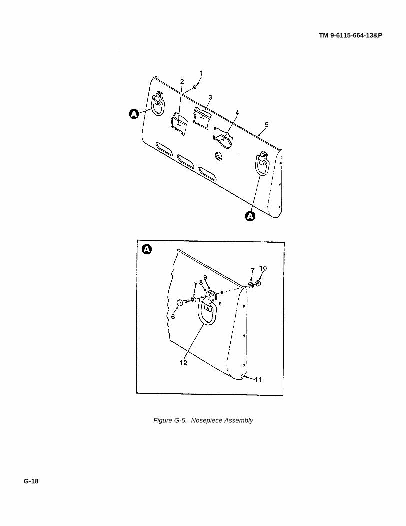
TM 9-6115-664-13&P
Figure G-5. Nosepiece Assembly
G-18

TM 9-6115-664-13&P
ITEM SMR. NSN CAGEC PART NUMBER DESCRIPTION QTYNO. CODE & USABLE ON CODE
GROUP 01 COVER ASSEMBLY(NOSEPIECE)
FIGURE G-5
1 PAOZZ F9948 101-301-191 CAP 62 PAOZZ 62502 96-9039 INSULATION 13 PAOZZ 62502 96-9098 INSULATION, STRIP 14 PAOZZ 62502 96-9040 INSULATION 15 PAOZZ 62502 96-9041 NOSEPIECE 16 PAOZZ 5305-00-543-2419 96906 MS90725-61 SCREW, CAP, HEXAGON, H 47 PAOZZ 5310-00-641-9464 96906 MS27183-13 WASHER, FLAT 88 PAOZZ 19220 1170-2 CLIP 29 PAOZZ 62502 96-9038 GASKET 210 PAOZZ 96906 MS17829-6C NUT, SELF-LOCKING, 411 MOOZZ 62502 96-9223 INSULATION, MAKE FROM X-102
(0CYC7), CUT TO 30.25 IN. 112 PAOZZ 19220 1170-3 RING 2
END OF FIGURE
G-19

TM 9-6115-664-13&P
Figure G-6. Cover (Lid) Assembly
G-20

TM 9-6115-664-13&P
ITEM SMR. NSN CAGEC PART NUMBER DESCRIPTION QTYNO. CODE & USABLE ON CODE
GROUP 02 COVER ASSEMBLY
FIGURE G-6
1 XBOOO 62502 96-9020 COVER ASSEMBLY 12 PAOZZ 62502 96-9012 T-LATCH ASSEMBLY 23 PAOZZ 5305-00-988-1727 96906 MS35206-283 SCREW, MACHINE 44 XBOZZ 62502 96-9018 BLOCK 25 XBOZZ 62502 96-9017 HINGE 26 XBOZZ 62502 96-9033 COVER 17 PAOZZ 62502 96-9032 INSULATION 18 PAOZZ 96906 MS35191-303 SCREW 109 PAOZZ 62502 96-9028 INSULATION 110 PAOZZ 88044 AN565-1032-6 SCREW, SET 211 PAOZZ 62502 96-9011 PAWL 212 PAOZZ 88044 AN565-416-20 SCREW, SET 413 PAOZZ 62502 96-9013 BLOCK 214 PAOZZ F9948 101-301-191 CAP 215 PAOZZ 62502 96-9029 INSULATION 116 XBOZZ 62502 96-9008 CROSSMEMBER 117 XBOZZ 62502 96-9006 BLOCK 218 PAOZZ 62502 96-9005 BLOCK 219 PAOZZ 9X737 B40R RING, HOIST 120 PAOZZ 96906 MS16997-84 SCREW, SOCKET, CAP 421 PAOZZ 62502 96-9009 INSULATION 122 PAOZZ 96906 MS17829-4C NUT, SELF-LOCKING, HE 223 PAOZZ 5310-00-809-5997 96906 MS51859-17 WASHER, FLAT 824 PAOZZ 96906 MS90725-26 SCREW, CAP, HEXAGON, H 225 PAOZZ 96906 MS17829-6C NUT, SELF-LOCKING 426 PAOZZ 5310-00-641-9464 96906 MS27183-13 WASHER, FLAT 427 PAOZZ F9948 101-301-191 CAP 428 PAOZZ 5305-00-226-4831 96906 MS90725-38 BOLT, MACHINE 329 PAOZZ 5310-00-637-9541 96906 MS35338-46 WASHER, LOCK 430 PAOZZ 5310-00-641-9464 96906 MS27183-13 WASHER, FLAT 431 PAOZZ 62502 96-9007 INSULATION 132 PAOZZ 5305-00-269-3211 96906 MS90725-60 SCREW, CAP, HEXAGON, H 133 XBOOO 62502 96-9010 COVER ASSEMBLY 134 PAOZZ 62502 96-9013 BLOCK 235 PAOZZ 54836 10-4855-AU T-LATCH ASSEMBLY 236 PAOZZ 5305-00-988-1727 96906 MS35206-283 SCREW, MACHINE 437 XBOZZ 62502 96-9019 COVER 138 PAOZZ 62502 96-9032 INSULATION 139 XBOZZ 62502 96-9017 HINGE 240 XBOZZ 62502 96-9018 BLOCK 241 PAOZZ 96906 MS35191-303 SCREW 1042 PAOZZ 62502 96-9014 INSULATION 1
G-21

TM 9-6115-664-13&P
ITEM SMR. NSN CAGEC PART NUMBER DESCRIPTION QTYNO. CODE & USABLE ON CODE
FIGURE G-6 (CONTINUED)
43 PAOZZ F9948 101-301-191 CAP 844 PAOZZ 88044 AN565-416-20 SCREW, SET 445 PAOZZ 62502 96-9011 PAWL 246 PAOZZ 88044 AN565-1032-6 SCREW, SET 247 PAOZZ 3A054 3896T1 SLEEVE, COMPRESSION 248 PAOZZ 3A054 3458T44 CABLE, 1/16 IN. DIA. X 18 IN. LG. 149 XBOZZ 62502 96-9027 HOLDER, CARD 1
END OF FIGURE
G-22

TM 9-6115-664-13&P
This PageIntentionally Left Blank
G-23

TM 9-6115-664-13&P
Figure G-7. Case Assembly (Enclosure) Components
G-24

TM 9-6115-664-13&P
ITEM SMR. NSN CAGEC PART NUMBER DESCRIPTION QTYNO. CODE & USABLE ON CODE
GROUP 03 CASE ASSEMBLY
FIGURE G-7
1 PAOZZ 62502 96-9079 DUCT 12 PAOZZ 5310-00-167-0818 88044 AN960-10 WASHER, FLAT 283 PAOZZ 5305-00-993-1848 96906 MS35207-265 SCREW, MACHINE 44 PAOZZ 62502 96-9099 INSULATION 15 PAOZZ 62502 96-9098 INSULATION 16 PAOZZ 0DG59 17/1600/1 MOUNT 47 PAOZZ 5310-00-641-9464 96906 MS27183-13 WASHER, FLAT 168 PAOZZ 5305-00-543-2419 96906 MS90725-61 SCREW, CAP, HEXAGON, H 89 PAOZZ 5935-01-097-9974 19207 11674728 COVER, NATO RECEPTAC 110 PAOZZ 5305-00-989-7434 96906 MS35207-263 SCREW, MACHINE 1411 PAOZZ 5310-00-045-3296 96906 MS35338-43 WASHER, LOCK 1412 PAOZZ 62502 96-9116 HANDLE 413 PAOZZ 96906 MS35190-273 SCREW, MACHINE 814 PAOZZ 62502 96-9089 BLOCK 415 PAOZZ 96906 MS21044-D3 NUT, SELF-LOCKING, HE 816 PAOZZ 62502 96-9114 SPACER 417 PAOZZ 5305-00-983-7470 96906 MS16997-153 SCREW, CAP, SOCKET HE 418 PAOZZ 5305-00-993-1851 96906 MS35207-267 SCREW, MACHINE 419 XBOZZ 62502 96-9045 DOOR ASSEMBLY, OIL FILTER
ACCESS 120 PAOZZ 62502 96-9083 HEADER ASSEMBLY 121 PAOZZ 96906 MS17829-6C NUT, SELF-LOCKING 822 PAOZZ 62502 96-9095 INSULATION 123 XBFZZ 62520 96-9120 CASE ASSEMBLY 124 PAOZZ F9948 101-301-191 CAP 625 PAOZZ 5305-00-978-9381 96906 MS16997-63 SCREW, CAP, SOCKET HE 426 PAOZZ 04EE5 10-4BSSN PLUNGER 227 PAOZZ 96906 MS17829-4C NUT, SELF-LOCKING, HE 428 PAOZZ 5310-00-619-4848 96906 MS27183-51 WASHER, FLAT 429 PAOZZ 07851 W0367-006 WASHER, WAVE, 1/4 430 PAOZZ 62502 96-9106 LATCH 231 PAOZZ 96906 MS27183-43 WASHER, FLAT 432 PAOZZ 96906 MS35206-232 SCREW, MACHINE 233 PAOZZ 62502 28014206 BRACKET 134 PAOZZ 96906 MS21044-D3 NUT, SELF-LOCKING 235 PAOZZ 96906 MS35207-261 SCREW, MACHINE 236 PAOZZ 13445 30172-15 BREAKER, CIRCUIT 137 PAOZZ 96906 MS21044N06 NUT, SELF-LOCKING 238 PAOZZ 74440 85094 METER, HOUR 139 PAOZZ 62502 96-9359-1 BEZEL
END OF FIGURE
G-25

TM 9-6115-664-13&P
Figure G-8. Case Assembly (Enclosure) Components
G-26

TM 9-6115-664-13&P
ITEM SMR. NSN CAGEC PART NUMBER DESCRIPTION QTYNO. CODE & USABLE ON CODE
GROUP 03 CASE ASSEMBLY
FIGURE G-8
1 XBOOO 62502 96-9050 DOOR ASSEMBLY, VALVE ACCESS 12 PAOZZ 5305-00-993-1851 96906 MS35207-267 SCREW, MACHINE 63 PAOZZ 5310-00-167-0818 88044 AN960-10 WASHER, FLAT 134 PAOZZ 5310-00-877-5798 96906 MS21044-D3 NUT, SELF-LOCKING, HE 135 PAOZZ 96906 MS35190-319 SCREW, PHIL HD 26 XBOZZ 62502 96-9092 DUCT ASSEMBLY 17 PAOZZ 19220 1170-3 RING 28 PAOZZ 62502 96-9038 GASKET 29 PAOZZ 19220 1170-2 CLIP 210 PAOZZ 96906 MS17829-6C NUT, SELF-LOCKING 411 PAOZZ 62502 96-9112 INSULATOR 112 PAOZZ 96906 MS35190-322 SCREW, PHIL HD, .375X 16X1.75 213 PAOZZ 5305-00-225-3839 62502 96-9077 BLOCK 114 PAOZZ 5310-00-582-5965 62502 96-9124 INSULATION 115 PAOZZ 5310-01-398-0341 96906 MS35207-265 SCREW, MACHINE 716 PAOZZ 62502 96-9097 INSULATION 117 PAOZZ 62502 96-9111 NAMEPLATE, DIRECTION INDICATOR 118 PAOZZ 5305-00-993-1848 0ATZ6 3706T131 STRAP 119 PAOZZ 0ATZ6 11355T29 CLAMP 120 PAOZZ 62502 96-9145 HOSE, FUEL, AUXILIARY 121 PAOZZ 0ATZ6 29695T91 STRAP 122 PAOZZ 62502 96-9094 INSULATION 1
END OF FIGURE
G-27

TM 9-6115-664-13&P
Figure G-9. Fan and Oil Cooler Assemblies
G-28

TM 9-6115-664-13&P
ITEM SMR. NSN CAGEC PART NUMBER DESCRIPTION QTYNO. CODE & USABLE ON CODE
GROUP 03 CASE ASSEMBLY
FIGURE G-9
1 PAOZZ 62502 96-9096 INSULA TION 12 PAOZZ F9948 101-301-191 CAP 23 PAOZZ 62502 96-9065 INSULATION 14 PAOZZ 5310-00-167-0818 88044 AN960-10 WASHER, FLAT 85 PAOZZ 5310-00-877-5798 96906 MS21044-D3 NUT, SELF-LOCKING, HE 46 XBOOO 62502 96-9060 OIL COOLER ASSEMBLY 1
(SEE FIGURE G-10 FOR PARTSBREAKDOWN)
7 PAOZZ 5305-00-989-7434 96906 MS35207-263 SCREW, MACHINE 38 PAOZZ 5310-00-045-3296 96906 MS35338-43 WASHER, LOCK 39 PAOZZ 5310-00-641-9464 96906 MS27183-13 WASHER, FLAT 610 PAOZZ 5310-00-637-9541 96906 MS35338-46 WASHER, LOCK 611 PAOZZ 5305-00-269-3211 96906 MS90725-60 SCREW, CAP, HEXAGON, H 612 PAOZZ 62502 3010.0379 FAN 113 PAOZZ 62502 3013.0032 BASE 414 PAOZZ 5310-00-809-3078 96906 MS27183-11 WASHER, FLAT 415 PAOZZ 5310-00-407-9566 96906 MS35338-45 WASHER, LOCK 416 PAOZZ 5305-00-115-9526 96906 MS90725-58 SCREW, CAP, HEXAGON, H 417 PAOZZ 5950-01-388-0744 34899 0443167251 SHIELDING, BEAD, ELEC 118 PAOZZ 5305-00-993-1848 96906 MS35207-265 SCREW, 10-32X3/4, PHI 4
END OF FIGURE
G-29

TM 9-6115-664-13&P
Figure G-10. Oil Cooler Assembly
G-30

TM 9-6115-664-13&P
ITEM SMR. NSN CAGEC PART NUMBER DESCRIPTION QTYNO. CODE & USABLE ON CODE
GROUP 0301 OIL COOLERASSEMBLY
FIGURE G-10
1 XBOZZ 62502 96-9066 COVER 12 PAOZZ 62502 2196-S GROMMET 23 XBOZZ 62502 96-9070 CLAMP, OIL COOLER 24 PAOZZ 5310-00-619-4848 96906 MS27183-51 WASHER, FLAT 65 PAOZZ 5305-00-068-0502 96906 MS16997-60 SCREW, CAP, HEXAGON, H 66 XBOZZ 0AKY4 24306E-606-666 HOSE ASSEMBLY, OIL COOLER 27 XBOZZ 62502 96-9071 INSULATOR, OIL COOLER 68 XBOZZ 62502 96-9069 BLOCK 29 PAOZZ 50184 ICS10412X-12R COOLER 1
B9CAMXS-S-0210
END OF FIGURE
G-31

(Figure G-11 Sheet 1 of 2)(Figure G-11 Sheet 2 of 2)
TM 9-6115-664-13&P
Figure G-11. Local Control Panel Assembly(Sheet 1 of 2)
G-32

TM 9-6115-664-13&P
Figure G-11. Local Control Panel Assembly(Sheet 2 of 2)
G-33

TM 9-6115-664-13&PP
ITEM SMR. NSN CAGEC PART NUMBER DESCRIPTION QTYNO. CODE & USABLE ON CODE
GROUP 04 LOCAL CONTROLPANEL ASSEMBLY
FIGURE G-11
1 PAOZZ 5305-00-993-1848 96906 MS35207-265 SCREW, MACHINE 52 PAOZZ 5310-00-167-0818 88044 AN960-10 WASHER, FLAT 53 PAOZZ 96906 MS34338-43 WASHER, LOCK 54 PAOOO 62502 96-9453 SWITCH ASSEMBLY, CONTROL 1
PANEL, LOCAL5 PAOZZ 1DU88 2TL1-50M SWITCH, START 16 PAOZZ 1DU88 8530K2 SWITCH, PREHEAT 17 PAOZZ 1DU88 8510K11 SWITCH, APU ON 18 PAOZZ 1DU88 1TL1-3 SWITCH, LOCAL/REMOTE 19 PAOZZ 62502 96-9453-1 HARNESS, WIRING 110 PAOZZ 62502 96-9450 CONNECTOR HARNESS 111 PAOZZ 5305-00-984-4992 96906 MS35206-232 SCREW, MACHINE 412 PAOZZ 96906 MS21004-N08 NUT, SELF-LOCKING 413 XBOZZ 62502 96-9452 PANEL 114 PAOZZ 5310-00-877-5798 13074 50151 SEAL, SWITCH 115 PAOZZ 19328 2051 CLAMP, CLIP, PLASTIC 216 XBOZZ 62502 96-9462 ENCLOSURE 117 PAOZZ 5305-00-984-4983 96906 MS35206-226 SCREW, MACHINE 618 PAOZZ 62502 96-9461 PCB ASSEMBLY, LOCAL CONTROL
PANEL 119 PAOFF 62502 96-9464 HARNESS, WIRING 120 PAOZZ 62502 96-9376-04 BODY, CONNECTOR 121 PAOZZ 5925-00-074-9180 77342 W23-X1A1G-5 BREAKER, CIRCUIT 1
END OF FIGURE
G-34

TM 9-6115-664-13&P
This PageIntentionally Left Blank
G-35

(Figure G-12 Sheet 1 of 2)(Figure G-12 Sheet 2 of 2)
TM 9-6115-664-13&P
Figure G-12. Remote Control Assembly(Sheet 1 of 2)
G-36

TM 9-6115-664-13&P
Figure G-12. Remote Control Assembly(Sheet 2 of 2)
G-37

TM 9-6115-664-13&P
ITEM SMR. NSN CAGEC PART NUMBER DESCRIPTION QTYNO. CODE & USABLE ON CODE
GROUP 05 REMOTE CONTROLPANEL ASSEMBLY
FIGURE G-12
1 PAOZZ 5305-00-071-2237 96906 MS90725-14 SCREW, CAP, HEXAGON, H 42 PAOZZ 3A054 9311K63 ISOLATOR, RIBBED BUS 43 XBOZZ 62502 96-9430 PLATE 14 XBOZZ 62502 96-9425 HOUSING, REMOTE CONTROL 15 PAOZZ 5310-00-167-0766 88044 AN970-4 WASHER, FLAT 46 PAOZZ 96906 MS17829-4C NUT, SELF-LOCKING, HE 47 PAOOO 62502 96-9431 SWITCH ASSEMBLY, REMOTE
CONTROL 18 PAOZZ 1DU88 1TL1-3 SWITCH, BATTLE-SHORT 19 PAOZZ 1DU88 8510K11 SWITCH, APU ON 110 PAOZZ 62502 96-9431-1 HARNESS, WIRING 111 PAOZZ 05VU8 E22GDB2 OPERATOR, PUSH-PULL 112 PAOZZ 05VU8 E22B1 CONTACT BLOCK, NC 113 PAOZZ 1DU88 8597K1 GUARD, SWITCH 114 PAOZZ 1DU88 8530K2 SWITCH, PREHEAT 115 PAOZZ 1DU88 2TL1-50M SWITCH, START 116 PAOZZ 5305-00-993-1848 96906 MS35207-265 SCREW, MACHINE 417 PAOZZ 96906 MS35338-43 WASHER, LOCK 618 PAOZZ 88044 AN960-10 WASHER, FLAT 619 XBOZZ 62502 96-9412 PANEL 120 PAOZZ 5305-00-984-4992 96906 MS35206-232 SCREW, MACHINE 421 PAOZZ 96906 MS21004-N08 NUT, SELF-LOCKING 422 PAOZZ 62502 96-9422 CABLE ASSEMBLY,
REMOTE CABLE 123 PAOZZ 62502 96-9404 PCB ASSEMBLY, REMOTE
CONTROL PANEL 124 PAOZZ 62502 MS24532-2 METER, VOLT 125 PAOZZ 5305-00-984-4983 96906 MS35206-226 SCREW, MACHINE 526 PAOZZ 5930-00-681-4394 19203 4001 SWITCH, PUSH 1
END OF FIGURE
G-38

TM 9-6115-664-13&P
This PageIntention ally Left Blank
G-39

(Figure G-13 Sheet 1 of 2)(Figure G-13 Sheet 2 of 2)
TM 9-6115-664-13&P
Figure G-13. NATO Receptacle and Filter/Separator Assemblies(Sheet 1 of 2)
G-40

TM 9-6115-664-13&P
Figure G-13. NATO Receptacle and Filter/Separator Assemblies(Sheet 2 of 2)
G-41

TM 9-6115-664-13&P
ITEM SMR. NSN CAGEC PART NUMBER DESCRIPTION QTYNO. CODE & USABLE ON CODE
GROUP 06 FUEL MODULE
FIGURE G-13
1 XBOZZ 62502 96-9151 COVER ASSEMBLY 12 XBOZZ 62502 96-9205 ENCLOSURE 13 PAOZZ 5305-00-984-7361 96906 MS35191-270 SCREW, MACHINE 24 PAOZZ 5310-00-045-3296 96906 MS35338-43 WASHER, LOCK 45 PAOZZ 5305-00-989-7434 96906 MS35207-263 SCREW, MACHINE 46 PAOZZ 62502 96-9156-2 STUD, FEED THRU 17 PAOZZ 62502 96-9156-3 STUD, FEED THRU 18 PAOZZ 62502 96-9156-1 STUD, FEED THRU 19 XBOZZ 62502 96-9160 PLATE 110 PAOZZ 96906 MS35691-29 NUT 111 PAOZZ 96906 MS35335-36 WASHER 112 PAOZZ 96906 MS35691-37 NUT 113 PAOZZ 96906 MS35335-37 WASHER 114 PAOZZ 96906 MS21044-N06 NUT, SELF LOCKING 315 PAOZZ 80205 NAS1149GN832P WASHER, FLAT 316 PAOZZ 5342-01-163-1299 72794 150003 BUSHING 317 PAOZZ 96906 MS35206-247 SCREW 318 PAOZZ 5305-00-993-1848 96906 MS35207-265 SCREW, MACHINE 419 PAOZZ 62502 96-9191 GASKET 120 PAOZZ 5935-01-097-9974 19207 11674728 COVER, NATO RECEPTAC 121 PAOZZ 62502 96-9158-3 CABLE ASSEMBLY 222 PAOZZ 62502 96-9158-4 CABLE ASSEMBLY 123 PAOZZ 96906 MS21044-N3 NUT, SELF-LOCKING, HE 424 PAOFF 62502 96-9157 CABLE ASSEMBLY 125 XBOZZ 4730-00-277-2448 79470 C5405X4X4 ELBOW, PIPE TO TUBE 126 PAOZZ 96906 MS35190-291 SCREW 227 XBOZZ 0AKY4 3169X4 PLUG 228 PAOZZ 62502 96-9166-8 HOSE ASSEMBLY 129 PAOZZ 2L549 33260 ELEMENT, SEPARATOR, FILTER 130 PAOZZ 62502 96-9166-1 HOSE ASSEMBLY 131 PAOZZ 96906 MS17829-4C NUT, SELF-LOCKING, HE 232 PAOZZ 5310-01-398-0341 80205 NAS1149G0432P WASHER, FLAT 233 PAOZZ 4730-01-096-3170 96906 C5405X5X4 ELBOW, PIPE TO TUBE 134 PAOZZ 62502 96-9165 FUEL/WATER SEPARATOR ASSEM 135 PAOZZ 62502 96-9202 DECAL, PRIMARY FUEL 1
END OF FIGURE
G-42
TM 9-6115-664-13&P
This PageIntentionally Left Blank
G-43

TM 9-6115-664-13&P
Figure G-14. Fuel Pump and Float Valve Housing Assemblies
G-44

TM 9-6115-664-13&P
ITEM SMR. NSN CAGEC PART NUMBER DESCRIPTION QTYNO. CODE & USABLE ON CODE
GROUP 06 FUEL MODULE
FIGURE G-14
1 PAOZZ 96906 MS17829-4C NUT, SELF-LOCKING, HE 22 PAOZZ 5310-01-398-0341 80205 NAS1149G0432P WASHER, FLAT 43 XBOOO 62502 96-9175 HOUSING ASSEMBLY 1
(SEE FIGURE G-16 FOR PARTSBREAKDOWN)
4 PAOOO 62502 96-9166-3 HOSE ASSEMBLY 15 XBOOO 62502 96-9170 PUMP ASSEMBLY 1
(SEE FIGURE G-15 FOR PARTSBREAKDOWN)
6 PAOZZ 80205 NAS1515F4H WASHER, RUBBER 47 XBOZZ 62502 96-9204 DECAL, FUEL PUMP 18 PAOZZ 5305-00-225-3839 96906 MS90725-8 SCREW, CAP, HEXAGON, H 29 PAOZZ 1DU88 6041H202 CONTACTOR 110 XBOZZ 62502 96-9196 PLATE 111 PAOZZ 5310-00-167-0766 88044 AN970-4 WASHER, FLAT 212 XBOZZ 62502 96-9203 DECAL, FLOAT BOWL 113 PAOZZ 96906 MS35190-291 SCREW 2
END OF FIGURE
G-45

TM 9-6115-664-13&P
Figure G-15. Fuel Pump Assembly
G-46

TM 9-6115-664-13&P
ITEM SMR NSN CAGEC PART NUMBER DESCRIPTION QTYNO. CODE & USABLE ON CODE
GROUP 0601 FUEL PUMP ASSEMBLY
FIGURE G-15
1 PAOZZ 62502 96-9166-2 HOSE ASSEMBLY 12 PAOZZ 0L4R8 3-520117-2 CONNECTOR, MALE CRIMP 13 PAOZZ 0L4R8 3-520107-2 CONNECTOR, FEMALE CRIMP 14 PAOZZ 0AKY4 C5205X4 FITTING, 1/8 MPTX#4 15 PAOZZ 71425 E1012 PUMP, FUEL 1
END OF FIGURE
G-47

TM 9-6115-664-13&P
Figure G-16. Float Valve Housing Assembly
G-48

TM 9-6115-664-13&P
ITEM SMR NSN CAGEC PART NUMBER DESCRIPTION QTYNO. CODE & USABLE ON CODE
GROUP 0602 FLOAT VALVEHOUSING ASSEMBLY
FIGURE G-16
1 PAOZZ 5305-00-406-6695 96906 MS35206-337 SCREW, MACHINE 42 PAOZZ 5310-00-045-3296 96906 MS35338-43 WASHER, LOCK 43 PAOZZ 62502 96-9179 COVER 14 PAOZZ 62502 96-9180 GASKET 15 PAOZZ 03479 15050527 PIN 16 PAOZZ 03479 15000162 FLOAT 17 PAOZZ 4730-00-427-5121 79470 3152X6 PLUG 18 PAOZZ 03479 15050525 HOUSING 19 PAOZZ 4730-00-014-4027 79470 3152X8 PLUG 110 PAOZZ 0AKY4 C5525X5 FITTING, ELBOW 111 PAOZZ 62502 96-9166-7 HOSE ASSEMBLY 112 XBOZZ 0BT82 1637-025800 VENT, BREATHER 113 PAOZZ 0AKY4 32206X6X2 REDUCER, BUSHING 114 PAOZZ 03479 15050526 NUT 115 PAOZZ 62502 96-9166-4 HOSE ASSEMBLY 116 PAOZZ 0AKY4 C5525X4 FITTING, ELBOW 117 PAOZZ 03479 15000159 VALVE 1
END OF FIGURE
G-49

(Figure G-17 Sheet 1 of 2)(Figure G-17 Sheet 2 of 2)
TM 9-6115-664-13&P
Figure G-17. Engine/Alternator Assembly(Sheet 1 of 2)
G-50

TM 9-6115-664-13&P
Figure G-17. Engine/Alternator Assembly(Sheet 2 of 2)
G-51

TM 9-6115-664-13&P
ITEM SMR NSN CAGEC PART NUMBER DESCRIPTION QTYNO. CODE & USABLE ON CODE
GROUP 07 ENGINE/ALTERNATORASSEMBLY
FIGURE G-17
1 XBFFF 62502 96-9305 ENGINE ASSEMBLY 1(SEE FIGURE G-19 FOR PARTSBREAKDOWN)
2 PAFFF 62502 96-9253 CABLE ASSEMBLY 13 PAFFF 62502 96-9252 CABLE ASSEMBLY 14 PAFZZ 0VKD6 96-9429-056 BOLT, HEX HEAD, M8X20 15 XBFFF 62502 96-9270 ALTERNATOR ASSEMBLY 1
(SEE FIGURE G-38 FOR PARTSBREAKDOWN)
6 XBFZZ 62502 96-9278 MOUNT, CASE 17 XBFFF 62502 96-9277 SHROUD ASSEMBLY 1
(SEE FIGURE G-18 FOR PARTSBREAKDOWN)
8 PAFZZ 96906 MS35207-265 SCREW 29 PAFZZ 5310-00-167-0818 88044 AN960-10 WASHER, FLAT 410 PAFZZ 96906 MS16997-64 SCREW 211 PAFZZ 5310-00-619-4848 96906 MS27183-51 WASHER, FLAT 412 PAFZZ 96906 MS17829-4C NUT, SELF-LOCKING, HE 213 XBFZZ 62502 96-9279 MOUNT, CASE 114 PAFZZ 5310-00-877-5798 96906 MS21044-D3 NUT, SELF-LOCKING, HE 215 PAFZZ 5305-00-993-1848 96906 MS35207-265 SCREW, MACHINE 316 PAFZZ 5310-00-045-3296 96906 MS35338-43 WASHER, LOCK 317 PAFZZ 5310-00-167-0818 88044 AN960-10 WASHER, FLAT 318 XBFZZ 62502 96-9285 SHROUD ASSEMBLY, FLYWHEEL 119 PAFZZ 62502 96-9249-105-SH SCREW 120 PAFZZ 62502 96-9268 SPACER 121 XBFZZ 62502 96-9266 COVER 122 PAFZZ 0VKD6 96-9249-138 BOLT, HEX HEAD, M10X110 723 PAFZZ 0VKD6 96-9247-6 WASHER, LOCK, M10 424 PAFZZ 0VKD6 96-9248-6 WASHER, FLAT, M10 425 XBFZZ 62502 96-9267 BRACKET 126 PAFZZ 86928 570-140-120N WASHER, FLAT 427 PAFZZ 62502 96-9158-4 CABLE ASSEMBLY 128 PAFZZ 62502 96-9158-3 CABLE ASSEMBLY 129 PAFZZ 0VKD6 96-9248-4 WASHER, FLAT, M8 1
END OF FIGURE
G-52

TM 9-6115-664-13&P
This PageIntentionally Left Blank
G-53

TM 9-6115-664-13&P
Figure G-18. Shroud Assembly
G-54

TM 9-6115-664-13&P
ITEM SMR NSN CAGEC PART NUMBER DESCRIPTION QTYNO. CODE & USABLE ON CODE
GROUP 0701 SHROUD ASSEMBLY
FIGURE G-18
1 PAFZZ 5310-00-167-0818 88044 AN960-10 WASHER, FLAT 82 PAFZZ 5305-00-993-1848 96906 MS35207-265 SCREW, MACHINE 33 PAFZZ 76761 N3129 REGULATOR, VOLTAGE 14 XBFZZ 62502 96-9275 BRACKET 15 PAFZZ 5305-00-989-7434 96906 MS35207-263 SCREW, MACHINE 26 PAFZZ 5310-00-045-3296 96906 MS35338-43 WASHER, LOCK 27 XBFZZ 62502 96-9282 GUARD, FINGER 18 XBFZZ 07851 AD44AH RIVET 49 XBFZZ 62502 96-9284 SHROUD 110 XBFZZ 96906 MS521059-3 PLATE, NUT 211 XBFZZ 62502 96-9283 DIVIDER, AIR FLOW 112 PAFZZ 5310-00-877-5798 96906 MS21044-D3 NUT, SELF-LOCKING, HE 313 XBFZZ 07851 GAMD34A RIVET 4
END OF FIGURE
G-55

TM 9-6115-664-13&P
Figure G-19. Engine Assembly Components
G-56

TM 9-6115-664-13&P
ITEM SMR NSN CAGEC PART NUMBER DESCRIPTION QTYNO. CODE & USABLE ON CODE
GROUP 0702 ENGINE ASSEMBLY
FIGURE G-19
1 XBOZZ 62502 96-9344 CAP 12 XBOZZ 62502 96-9345 CABLE, LANYARD 13 PAOZZ 88044 AN530-2-4 SCREW, MACHINE 14 PAOZZ 62502 96-9355 MODULE ASSEMBLY 15 PAOZZ 0VKD6 96-9249-084-HH BOLT, HEX HEAD, M10X2 0X15 46 PAOZZ 0VKD6 96-9247-5 WASHER, LOCK 47 PAOZZ 0VKD6 96-9248-5 WASHER, FLAT, M10 48 PAFZZ 0VKD6 96-9249-092-HH BOLT, HEX HEAD 49 PAFZZ 0VKD6 96-9247-5 WASHER, LOCK 410 PAFZZ 0VKD6 96-9248-5 WASHER, FLAT, M10 411 PAFZZ D8889 856.002.4 INSULATOR, COUPLING 112 XBFZZ D8889 440.064.4 SPACER, COUPLING 113 PAOZZ 62502 96-9251 CABLE ASSEMBLY 114 XBFFF D8889 43F ENGINE 115 PAOZZ D8889 541.050.2E FILTER, OIL 116 PAOZZ 06YT7 181SN NUT, SLEEVE 117 XBOZZ 62502 96-9352 ADAPTER, FILTER, OIL 118 PAOZZ 0AKY4 C5355X6X6 ELBOW 219 XBOOO 62502 96-9325 EXHAUST ASSEMBLY 120 PAOZZ 62502 96-9326 PIPE ASSEMBLY 121 PAOZZ C4519 191253139H CLAMP 122 PAOZZ 62502 96-9330 HOSE 123 PAOZZ 0FDK1 913-1763 COVER 124 PAOZZ 12088 PC501B CLAMP 125 PAOZZ 62502 96-9327 PIPE ASSEMBLY 1
END OF FIGURE
G-57

TM 9-6115-664-13&P
Figure G-20. Engine Air Filter
G-58

TM 9-6115-664-13&P
ITEM SMR NSN CAGEC PART NUMBER DESCRIPTION QTYNO. CODE & USABLE ON CODE
GROUP 0702 ENGINE ASSEMBLY
FIGURE G-20
1 PAOZZ 96906 MS35842-12 CLAMP, HOSE 12 PAOZZ 62502 96-9317 HOSE 13 XBOZZ 62502 96-9310 COVER 14 PAOZZ 62502 96-9309 SCREW ASSEMBLY 15 PAOZZ 86928 5613-49-062 WASHER, NEOPRENE 16 PAOZZ 6E876 94800A740 RETAINER 17 PAOZZ 4Z382 CA6306 FILTER 18 PAOZZ 0VKD6 96-9429-058-HH BOLT, HEX HEAD, M8X30 39 PAOZZ 0VKD6 96-9247-4 WASHER, LOCK, M8 310 PAOZZ 0VKD6 96-9248-4 WASHER, FLAT, M8 311 PAOZZ 62502 96-9314 GUARD, INTAKE, MESH 112 PAOZZ 62502 96-9312 SCREW, JACK, HEX 113 PAOZZ 96906 MS17829-4C NUT, SELF-LOCKING, HE 314 PAOZZ 5310-01-398-0341 80205 NAS1149G0432P WASHER, FLAT 615 XBOZZ 62502 96-9316 PLATE 116 XBOZZ 62502 96-9315 BASE 117 PAOZZ 5305-00-225-3839 96906 MS90725-8 SCREW, CAP, HEXAGON, H 3
END OF FIGURE
G-59

TM 9-6115-664-13&P
Figure G-21. Exhaust Duct Assembly
G-60

TM 9-6115-664-13&P
ITEM SMR NSN CAGEC PART NUMBER DESCRIPTION QTYNO. CODE & USABLE ON CODE
GROUP 0702 ENGINE ASSEMBLY
FIGURE G-21
1 PAOZZ 62502 96-9340 DUCT ASSEMBLY 12 PAOZZ 0VKD6 96-9249-084-HH BOLT, HEX HEAD, M10X20X15 23 PAOZZ 0VKD6 96-9247-5 WASHER, LOCK 24 PAOZZ 0VKD6 96-9248-5 WASHER, FLAT, M10 25 PAOZZ 0VKD6 96-9248-3 WASHER, FLAT, M6 26 PAOZZ 0VKD6 96-9247-3 WASHER, LOCK, M6 27 PAOZZ 0VKD6 96-9249-029-SH BOLT, M6X20MM, SHCS 28 PAOZZ 96906 MS35207-267 SCREW 19 PAOZZ 88044 AN960-10 WASHER, FLAT 110 PAOZZ 96906 MS35338-43 WASHER, LOCK 1
END OF FIGURE
G-61

TM 9-6115-664-13&P
Figure G-22. Engine Start Solenoid
G-62

TM 9-6115-664-13&P
ITEM SMR NSN CAGEC PART NUMBER DESCRIPTION QTYNO. CODE & USABLE ON CODE
GROUP 0702 ENGINE ASSEMBLY
FIGURE G-22
1 PAOZZ 5930-00-729-8108 81640 W1016 SWITCH 12 PAOZZ D8889 547.407.1 SOLENOID 13 PAOZZ D8889 890.08.02 WASHER, FLAT 44 PAOZZ D8889 890.38.03 NUT, HEX, M6 25 PAOZZ D8889 555.164.2 CLIP, YOKE 16 PAOZZ D8889 890.37.09 SCREW 27 XBOZZ D8889 923.931.4 BRACKET 18 PAOZZ 0VKD6 96-9249-056-FH SCREW 29 PAOZZ D8889 890.10.03 WASHER, LOCK, M6 2
END OF FIGURE
G-63

TM 9-6115-664-13&P
Figure G-23. Fuel Filter (In-Line)
G-64

TM 9-6115-664-13&P
ITEM SMR NSN CAGEC PART NUMBER DESCRIPTION QTYNO. CODE & USABLE ON CODE
GROUP 0702 ENGINE ASSEMBLY
FIGURE G-23
1 PAOZZ 96906 MS3367-5 WIRE, TIE 22 PAOZZ 80205 NAS1149G0632P WASHER, FLAT 23 PAOZZ 5305-00-115-9526 96906 MS90725-58 SCREW, CAP, HEXAGON, H 14 XBOZZ 62502 96-9257 BRACKET 15 PAOZZ 62502 96-9166-6 HOSE ASSEMBLY, FUEL, RETURN 16 PAOZZ 0AKY4 C5506X5 FITTING 17 PAOZZ 0AKY4 C5506X4 FITTING 18 PAOZZ 62502 96-9166-5 HOSE ASSEMBLY 19 PAOZZ 96906 MS17829-6C NUT, SELF-LOCKING 110 XBFZZ D8889 922.077.2 CLAMP 111 XBFZZ D8889 923.892.4 BRACKET 112 PAOZZ D8889 541.038.2 FILTER, FUEL 113 PAFZZ D8889 971.495.5 PIPE, FUEL 1
END OF FIGURE
G-65

TM 9-6115-664-13&P
Figure G-24. Oil Drain Assembly
G-66

TM 9-6115-664-13&P
ITEM SMR NSN CAGEC PART NUMBER DESCRIPTION QTYNO. CODE & USABLE ON CODE
GROUP 0702 ENGINE ASSEMBLY
FIGURE G-24
1 XBOZZ 62502 96-9362 DRAIN ASSEMBLY, OIL 12 PAOZZ 62502 96-9366 BOLT, MODIFIED 13 PAOZZ 0ELG7 853009-16 SEAL, WASHER 14 PAOZZ 62502 96-9364 SPACER 1
END OF FIGURE
G-67

TM 9-6115-664-13&P
Figure G-25. Air Heat Glow Plug and Temperature Switch
G-68

TM 9-6115-664-13&P
ITEM SMR NSN CAGEC PART NUMBER DESCRIPTION QTYNO. CODE & USABLE ON CODE
GROUP 070201 DIESEL ENGINE
FIGURE G-25
1 PAOZZ D8889 555.022.2 PLUG, GLOW 22 PAOZZ D8889 982.334.4 PIPE 23 PAOZZ D8889 515.103.4 ADAPTOR 14 PAOZZ D8889 238.018.2 SWITCH, TEMPERATURE 1
END OF FIGURE
G-69

TM 9-6115-664-13&P
Figure G-26. Fuel Injection Pump
G-70

TM 9-6115-664-13&P
ITEM SMR NSN CAGEC PART NUMBER DESCRIPTION QTYNO. CODE & USABLE ON CODE
GROUP 070201 DIESEL ENGINE
FIGURE G-26
1 PAOZZ D8889 890.74.16 WASHER, COPPER, A12X1 22 PAOZZ D8889 890.77.02 BOLT, BANJO, M12X1.5 13 PAOZZ D8889 890.31.28 SCREW, HEX, M6X12 14 PAOZZ D8889 890.11.03 WASHER, SPRING, A6 15 PAOZZ D8889 922.005.4 CLAMP, FUEL LINE 16 PAOZZ D8889 971.481.5 PIPE, FUEL PRESSURE 17 PAFZZ D8889 890.38.05 NUT, HEX, M8 28 PAFZZ D8889 890.74.06 WASHER, COPPER, A8X12 29 PAFZZ D8889 945.009.4 SHIM, 0.2MM, INJECTIO 19 PAFZZ D8889 945.018.4 SHIM, 0.4MM, INJECTIO 19 PAFZZ D8889 945.036.4 SHIM, 1.0MM, INJECTIO 110 PAFZZ D8889 770.201.4 GASKET 111 PAFZZ D8889 890.28.17 STUD, M8X30, INJECTION PUMP 112 PAFZZ D8889 890.28.14 STUD, M8X20, INJECTION PUMP 113 PAFZZ D8889 536.306.2 VALVE, PRESSURE 114 PAOZZ D8889 971.482.5 PIPE, FUEL 115 PAFZZ D8889 890.74.48 WASHER 216 PAFZZ D8889 973.028.5 PIPE, OIL SCAVENGE 117 PAFZZ D8889 890.77.06 BOLT, BANJO, M10X1 118 PAFZZ D8889 536.033.1 PUMP, FUEL INJECTION 119 PAFZZ D8889 536.219.2 SEAL 120 PAFZZ D8889 536.307.2 VALVE, PRESSURE 121 PAFZZ D8889 536.308.2 SPRING 122 PAFZZ D8889 536.305.2 TAPPET, ROLLER 1
END OF FIGURE
G-71

TM 9-6115-664-13&P
Figure G-27. Fuel Feed Pump
G-72

TM 9-6115-664-13&P
ITEM SMR NSN CAGEC PART NUMBER DESCRIPTION QTYNO. CODE & USABLE ON CODE
GROUP 070201 DIESEL ENGINE
FIGURE G-27
1 PAOZZ D8889 175.078.1 PUMP, MECHANICAL FUE 12 PAOZZ D8889 890.38.03 NUT, HEX, 6MM 23 PAOZZ D8889 890.11.03 WASHER, SPRING, A6 24 PAOZZ D8889 515.357.2 BOLT, BANJO, M8 25 PAOZZ D8889 890.74.06 WASHER, COPPER, A8X12 26 PAOZZ D8889 850.067.4 GASKET 27 PAOZZ D8889 847.123.4 GASKET V
END OF FIGURE
G-73

TM 9-6115-664-13&P
Figure G-28. Engine Oil Components
G-74
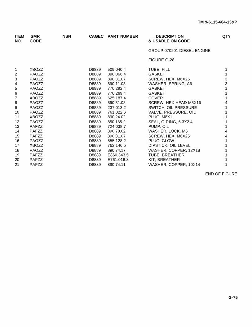
TM 9-6115-664-13&P
ITEM SMR NSN CAGEC PART NUMBER DESCRIPTION QTYNO. CODE & USABLE ON CODE
GROUP 070201 DIESEL ENGINE
FIGURE G-28
1 XBOZZ D8889 509.040.4 TUBE, FILL 12 PAOZZ D8889 890.066.4 GASKET 13 PAOZZ D8889 890.31.07 SCREW, HEX, M6X25 34 PAOZZ D8889 890.11.03 WASHER, SPRING, A6 35 PAOZZ D8889 770.292.4 GASKET 16 PAOZZ D8889 770.269.4 GASKET 17 XBOZZ D8889 625.187.4 COVER 18 PAOZZ D8889 890.31.08 SCREW, HEX HEAD M8X16 49 PAOZZ D8889 237.013.2 SWITCH, OIL PRESSURE 110 PAOZZ D8889 761.022.6 VALVE, PRESSURE, OIL 111 XBOZZ D8889 890.24.02 PLUG, M8X1 112 PAOZZ D8889 850.185.2 SEAL, O-RING, 6.3X2.4 113 PAFZZ D8889 724.038.7 PUMP, OIL 114 PAFZZ D8889 890.78.02 WASHER, LOCK, M6 415 PAFZZ D8889 890.31.07 SCREW, HEX, M6X25 416 PAOZZ D8889 555.128.2 PLUG, GLOW 117 XBOZZ D8889 762.146.5 DIPSTICK, OIL LEVEL 118 PAOZZ D8889 890.74.17 WASHER, COPPER, 12X18 119 PAFZZ D8889 E860.343.5 TUBE, BREATHER 120 PAFZZ D8889 E761.016.8 KIT, BREATHER 121 PAFZZ D8889 890.74.11 WASHER, COPPER, 10X14 1
END OF FIGURE
G-75

TM 9-6115-664-13&P
Figure G-29. Camshaft
G-76

TM 9-6115-664-13&P
ITEM SMR NSN CAGEC PART NUMBER DESCRIPTION QTYNO. CODE & USABLE ON CODE
GROUP 070201 DIESEL ENGINE
FIGURE G-29
1 PAFZZ D8889 890.31.10 SCREW, HEX, M8X20 82 PAFZZ D8889 890.31.11 SCREW, HEX, M8X25 13 PAFZZ D8889 512.094.4 SCREW, HEX 14 PAFZZ D8889 890.10.03 WASHER, LOCK, A6 15 PAFZZ D8889 770.270.4 GASKET 16 PAFZZ D8889 721.126.7 CAMSHAFT ASSEMBLY 17 XBFZZ D8889 917.287.4 COVER 18 PAFZZ D8889 770.274.4 GASKET 19 PAFZZ D8889 890.95.10 SCREW, SOCKET HEAD 210 XBFZZ D8889 118.127.4 GUIDE, CRANK HANDLE 111 PAFZZ D8889 890.31.08 SCREW, HEX, M8X1 3
END OF FIGURE
G-77

TM 9-6115-664-13&P
Figure G-30. Engine Speed Controls
G-78

TM 9-6115-664-13&P
ITEM SMR NSN CAGEC PART NUMBER DESCRIPTION QTYNO. CODE & USABLE ON CODE
GROUP 070201 DIESEL ENGINE
FIGURE G-30
1 PAFZZ D8889 514.085.2 NUT, HEX, M8 12 PAFZZ D8889 890.02.09 WASHER, 8X14X0.5 13 PAFZZ D8889 465.177.4 BUSHING 14 XBFZZ D8889 890.02.24 WASHER, 5X10X1 15 XBFZZ D8889 508.019.4 PIN, THREADED 16 XBFZZ D8889 890.74.09 WASHER, COPPER, A8X14 17 XBFZZ D8889 514.105.4 NUT, COLLAR 18 PAFZZ D8889 890.38.05 NUT, HEX, M8 19 PAFZZ D8889 890.66.03 WASHER, TOOTH, 18.4 110 XBFZZ D8889 905.211.4 LEVER 111 PAFZZ D8889 521.009.4 RING, SPACER 112 XBFZZ D8889 E722.074.8 SPEED CONTROL 113 PAFFF D8889 714.014.8 PRIMER ASSEMBLY 114 PAFZZ D8889 415.153.4 BOLT, THREADED 115 PAFZZ D8889 807.011.4 SPRING 116 PAFZZ D8889 905.214.5 LEVER 117 PAFZZ D8889 890.08.01 WASHER, 5.3 118 PAFZZ D8889 514.097.2 NUT, HEX 1
END OF FIGURE
G-79

TM 9-6115-664-13&P
Figure G-31. Starter
G-80

TM 9-6115-664-13&P
ITEM SMR NSN CAGEC PART NUMBER DESCRIPTION QTYNO. CODE & USABLE ON CODE
GROUP 070201 DIESEL ENGINE
FIGURE G-31
1 PAOZZ D8889 547.206.1 STARTER 12 PAOZZ D8889 890.31.11 SCREW, HEX, M8X25 43 PAOZZ D8889 890.31.30 SCREW, HEX, M8X80 24 PAOZZ D8889 547.070.2 BUSHING, STARTER 1
END OF FIGURE
G-81

TM 9-6115-664-13&P
Figure G-32. Flywheel and Ring Gear
G-82

TM 9-6115-664-13&P
ITEM SMR NSN CAGEC PART NUMBER DESCRIPTION QTYNO. CODE & USABLE ON CODE
GROUP 070201 DIESEL ENGINE
FIGURE G-32
1 XBFZZ D8889 751.103.4 SHIELD 12 PAFZZ D8889 890.31.28 SCREW, HEX, M6X12 23 PAFZZ D8889 890.08.02 WASHER 44 PAFZZ D8889 890.95.08 SCREW, SOCKET HEAD C 35 PAFZZ D8889 890.66.04 WASHER, TOOTH, V8.4 36 PAFZZ D8889 911.004.4 SEGMENT 37 PAFZZ D8889 890.59.51 SEAL, OIL, 65X100X8 18 XBFZZ D8889 738.293.4 FLYWHEEL 19 PAFZZ D8889 453.002.4 GEAR, RING 110 PAFZZ D8889 890.38.07 NUT, HEX, 10MM 611 PAFZZ D8889 890.10.07 WASHER, LOCK, A10 612 XBFZZ D8889 727.055.4 COVER 113 PAFZZ D8889 770.122.4 GASKET 114 PAFZZ D8889 890.31.28 SCREW, HEX, M6X12 215 PAFZZ D8889 890.08.02 WASHER 416 PAFZZ D8889 522.019.4 WASHER 1
END OF FIGURE
G-83

TM 9-6115-664-13&P
Figure G-33. Rocker Arm and Fuel Injector Assemblies
G-84

TM 9-6115-664-13&P
ITEM SMR NSN CAGEC PART NUMBER DESCRIPTION QTYNO. CODE & USABLE ON CODE
GROUP 070201 DIESEL ENGINE
FIGURE G-33
1 PAOZZ D8889 890.38.03 NUT, HEX, 6MM 22 PAOZZ D8889 890.10.03 WASHER, LOCK, A6 23 XBOZZ D8889 928.093.4 FLANGE 14 PAOZZ D8889 537.015.1 INJECTOR, FUEL 15 PAOZZ D8889 515.353.2 BOLT, BANJO, M6 16 PAOZZ D8889 890.74.04 WASHER, COPPER, A6X10 27 PAOZZ D8889 971.486.5 PIPE, FUEL 18 PAOZZ D8889 850.195.4 WASHER 19 XBFFF D8889 731.226.8 CYLINDER HEAD ASSEMBLY 1
(SEE FIGURE G-35 FOR PARTSBREAKDOWN)
10 PAFZZ D8889 771.003.4 GASKET 111 PAFZZ D8889 921.026.4 TUBE, PUSH ROD 112 PAFZZ D8889 850.197.4 SEAL, O-RING, 32X4 113 PAFZZ D8889 770.290.4 GASKET 114 XBFZZ D8889 616.070.4 MANIFOLD, EXHAUST 115 XBFZZ D8889 890.28.32 STUD, M10X25 216 PAFZZ D8889 514.104.2 NUT, HEX, M10 217 PAFZZ D8889. 890.37.26 SCREW, HEX, M8X55 218 PAFZZ D8889 890.37.20 SCREW, HEX, M8X25 219 PAFZZ D8889 890.10.05 WASHER, LOCK, A8 420 PAFZZ D8889 522.022.4 WASHER 221 PAFZZ D8889 890.38.07 NUT, HEX, 10MM 222 PAFZZ D8889 890.54.02 NUT, CAP, HEX, M10 223 PAOZZ D8889 770.288.4 GASKET 124 XBOZZ D8889 651.051.4 CAP, VALVE 125 PAOZZ D8889 890.11.03 WASHER, SPRING, A6 426 PAOZZ D8889 890.36.95 SCREW, HEX, M6X55 427 PAFZZ D8889 890.67.05 WASHER, RETAINING 228 PAFZZ D8889 415.156.4 BOLT, ROCKER 129 PAFZZ D8889 633.053.5 ARM, ROCKER 130 PAFZZ D8889 633.054.5 ARM, ROCKER 1
END OF FIGURE
G-85

TM 9-6115-664-13&P
Figure G-34. Push Rods
G-86

TM 9-6115-664-13&P
ITEM SMR NSN CAGEC PART NUMBER DESCRIPTION QTYNO. CODE & USABLE ON CODE
GROUP 070201 DIESEL ENGINE
FIGURE G-34
1 PAFZZ D8889 421.069.4 ROD, PUSH, INLET 12 PAFZZ D8889 890.31.10 SCREW, HEX, M8X20 23 PAFZZ D8889 424.021.4 GUIDE, TAPPET 14 PAFZZ D8889 770.277.4 GASKET 15 PAFZZ D8889 423.022.4 TAPPET 26 PAFZZ D8889 850.011.4 SEAL, O-RING, 32X4 17 PAFZZ D8889 421.070.4 ROD, PUSH, OUTLET 1
END OF FIGURE
G-87

TM 9-6115-664-13&P
Figure G-35. Cylinder Head Assembly
G-88

TM 9-6115-664-13&P
ITEM SMR NSN CAGEC PART NUMBER DESCRIPTION QTYNO. CODE & USABLE ON CODE
GROUP 07020101 CYLINDER HEADASSEMBLY
FIGURE G-35
1 XBFZZ D8889 890.28.66 STUD, M6X40 22 PAFZZ D8889 427.043.4 CONE, VALVE, INLET 13 PAFZZ D8889 427.044.4 CONE, VALVE, OUTLET 14 PAFZZ D8889 890.77.06 BOLT, BANJO, M10X1 15 PAFZZ D8889 890.74.78 WASHER 26 PAFZZ D8889 426.032.4 GUIDE, VALVE, OUTLET 17 PAFZZ D8889 927.022.4 WASHER 28 PAFZZ D8889 426.031.4 GUIDE, VALVE, INLET 19 PAFZZ D8889 861.104.2 SEAL 210 PAFZZ D8889 805.092.4 SPRING 211 PAFZZ D8889 531.009.4 PLATE 212 PAFZZ D8889 E527.007.4 COTTER, VALVE 2
END OF FIGURE
G-89
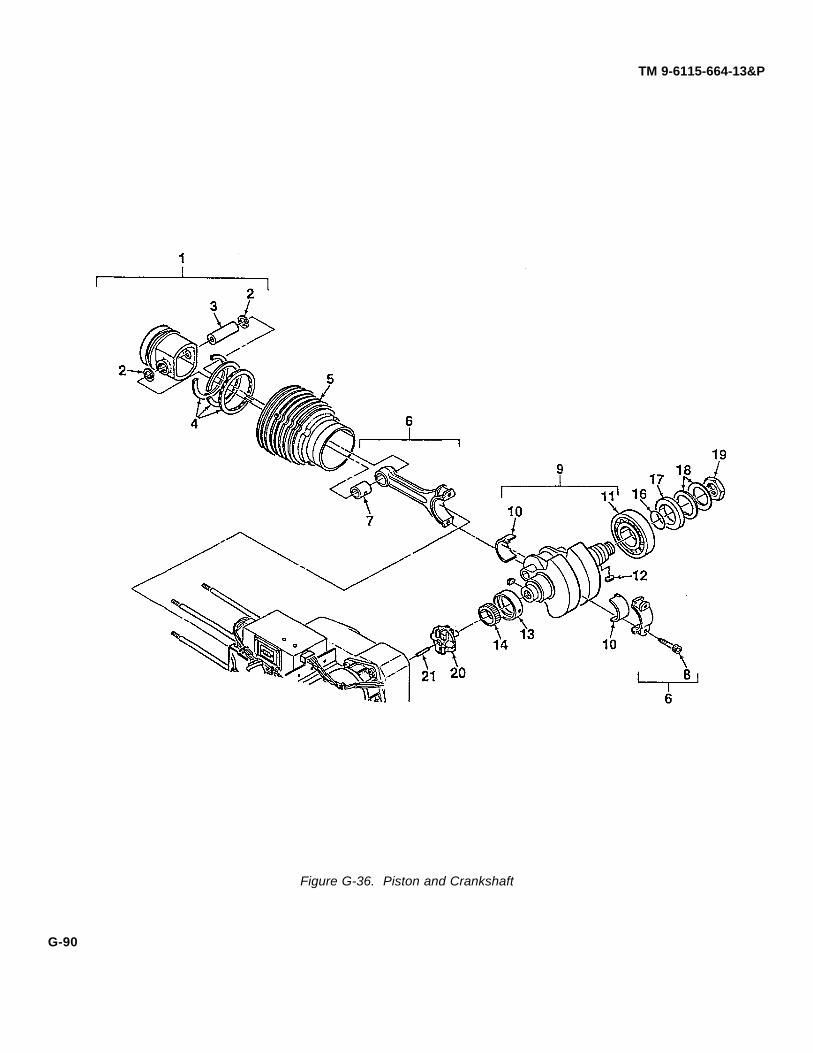
TM 9-6115-664-13&P
Figure G-36. Piston and Crankshaft
G-90

TM 9-6115-664-13&P
ITEM SMR NSN CAGEC PART NUMBER DESCRIPTION QTYNO. CODE & USABLE ON CODE
GROUP 070201 DIESEL ENGINE
FIGURE G-36
1 PAFFF D8889 725.125.8 PISTON ASSEMBLY 12 XBFZZ D8889 890.20.33 RING, RETAINING, 26X1 23 XBFZZ D8889 418.017.4 PIN, PISTON 14 PAFZZ D8889 535.143.1 RING SET, PISTON 15 XBFZZ D8889 730.058.4 CYLINDER 16 PAFFF D8889 726.036.5 CONNECTING ROD 17 XBFZZ D8889 465.169.4 BUSHING 18 PAFZZ D8889 890.31.90 SCREW, HEX, M10X11X45 29 PAFFF D8889 715.093.8 CRANKSHAFT ASSEMBLY 110 XBFZZ D8889 470.022.4 SHELL, BEARING 110 XBFZZ D8889 470.023.4 SHELL, BEARING 110 XBFZZ D8889 470.024.4 SHELL, BEARING 111 XBFZZ D8889 800.017.2 BEARING, ROLLER 112 XBFZZ D8889 890.68.10 KEY, FITTING, A8X5X20 113 XBFZZ D8889 775.038.4 BUSHING, MAIN 113 XBFZZ D8889 775.039.4 BUSHING, MAIN 113 XBFZZ D8889 775.040.4 BUSHING, MAIN 114 XBFZZ D8889 452.134.4 GEAR 115 XBFZZ D8889 907.001.4 KEY, FITTING 116 PAFZZ D8889 850.013.4 SEAL, O-RING, 40X1.5 117 PAFZZ D8889 519.038.4 RING, ANGLE 118 PAFZZ D8889 804.002.4 WASHER, BELLEVILLE 219 PAFZZ D8889 514.001.4 NUT, FLYWHEEL 120 PAFZZ D8889 540.051.1 GOVERNOR, 3000E MIN-1 121 PAFZZ D8889 890.61.05 PIN, GOVERNOR 1
END OF FIGURE
G-91
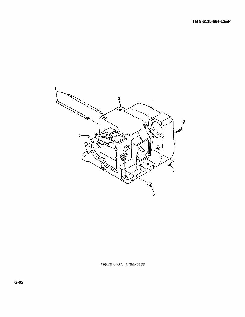
TM 9-6115-664-13&P
Figure G-37. Crankcase
G-92

TM 9-6115-664-13&P
ITEM SMR NSN CAGEC PART NUMBER DESCRIPTION QTYNO. CODE & USABLE ON CODE
GROUP 070201 DIESEL ENGINE
FIGURE G-37
1 XBFZZ D8889 512.006.4 STUD 42 XBFFF D8889 711.612.5 CRANKCASE 13 XBFZZ D8889 512.113.4 STUD 64 XBFZZ D8889 861.096.2 PIPE, SPOUT 15 PAFZZ D8889 4658.006.4 BUSHING 16 XBFZZ D8889 890.28.03 STUD, M6X16 2
END OF FIGURE
G-93

TM 9-6115-664-13&P
Figure G-38. Alternator Assembly
G-94

TM 9-6115-664-13&P
ITEM SMR NSN CAGEC PART NUMBER DESCRIPTION QTYNO. CODE & USABLE ON CODE
GROUP 0703 ALTERNATOR ASSEMBLY
FIGURE G-38
1 PAFZZ 76761 N1379 ALTERNATOR 12 XBFZZ 62502 96-9292 COUPLING, MODIFIED 13 PAFZZ 88044 AN565928-6 SCREW, SET 14 XBFZZ 62502 96-9295 HOUSING, FLYWHEEL 15 PAFZZ 5310-00-641-9464 96906 MS27183-13 WASHER, FLAT 26 PAFZZ 5310-00-637-9541 96906 MS35338-46 WASHER, LOCK 27 PAFZZ 5305-00-115-9526 96906 MS90725-58 SCREW, CAP, HEXAGON, H 28 XBFZZ 62502 96-9307 SLING 19 PAFZZ 5305-00-071-2072 80204 MS90725-116 SCREW, CAP, HEXAGON, H 410 PAFZZ 5310-00-584-5272 96906 MS35338-48 WASHER, LOCK 411 PAFZZ 5310-00-809-5997 96906 MS27183-17 WASHER, FLAT 412 PAFZZ 62502 96-9293 SEAL 113 PAFZZ 0VKD6 96-9249-090-HH BOLT, HEX HD, M10X35 414 PAFZZ 0VKD6 96-9247-5 WASHER, LOCK 415 PAFZZ D8889 415.079.4 LUG, DRIVE 4
END OF FIGURE
G-95

TM 9-6115-664-13&P
PART NUMBER INDEX
FSCM PART NUMBER STOCK NUMBER FIGURE NO ITEM NO
07851 AD44AH 18 888044 AN530-2-4 19 388044 AN565-1032-6 6 1088044 AN565-1032-6 6 4688044 AN565-416-20 6 1288044 AN565-416-20 6 4488044 AN565928-6 38 388044 AN960-10 5310-00-167-0818 3 288044 AN960-10 5310-00-167-0818 4 888044 AN960-10 5310-00-167-0818 4 1188044 AN960-10 5310-00-167-0818 8 388044 AN960-10 5310-00-167-0818 9 488044 AN960-10 5310-00-167-0818 11 288044 AN960-10 5310-00-167-0818 17 988044 AN960-10 5310-00-167-0818 17 1788044 AN960-10 5310-00-167-0818 18 188044 AN970-4 5310-00-167-0766 12 588044 AN970-4 5310-00-167-0766 14 119X737 B40R 6 194Z382 CA6306 20 70AKY4 C5205X4 15 479470 C5405X4X4 4730-00-277-2448 13 250AKY4 C5405X5 16 1496906 C5405X5X4 4730-01-096-3170 13 330AKY4 C5506X4 23 70AKY4 C5506X5 23 60AKY4 C5525X4 16 190AKY4 C5525X5 16 1871425 E1012 15 5D8889 E108.078.8 32 1205VU8 E22B1 12 1205VU8 E22GDB2 12 11D8889 E527.007.2 35 12D8889 E761.016.8 28 20D8889 E860.343.5 28 1950184 ICS10412X-12RB9C 10 9
AMXS-S-021096906 MS16997-153 5305-00-983-7470 7 1796906 MS16997-60 5305-00-068-0502 10 596906 MS16997-63 5305-00-978-9381 7 2596906 MS16997-64 17 1096906 MS16997-82 3 996906 MS16997-84 6 2096906 MS17829-4C 6 22
G-96

TM 9-6115-664-13&P
FSCM PART NUMBER STOCK NUMBER FIGURE NO ITEM NO
96906 MS17829-4C 7 2796906 MS17829-4C 12 696906 MS17829-4C 13 3196906 MS17829-4C 14 196906 MS17829-4C 17 1296906 MS17829-4C 20 1396906 MS17829-6C 2 396906 MS17829-6C 5 1096906 MS17829-6C 6 2596906 MS17829-6C 7 2196906 MS17829-6C 8 1096906 MS17829-6C 23 996906 MS17829-8C 2 1096906 MS21004-N08 11 1296906 MS21004-N08 11 1996906 MS21004-N08 12 196906 MS21044-D3 5310-00-877-5798 3 1596906 MS21044-D3 5310-00-877-5798 4 796906 MS21044-D3 5310-00-877-5798 8 496906 MS21044-D3 5310-00-877-5798 9 596906 MS21044-D3 5310-00-877-5798 11 2596906 MS21044-D3 5310-00-877-5798 17 1496906 MS21044-D3 5310-00-877-5798 18 896906 MS21044-N06 13 1496906 MS21044-N3 13 2396906 MS21045-4S 22 296906 MS21919-12 4 996906 MS24532-2 12 2796906 MS27183-11 5310-00-809-3078 4 2196906 MS27183-11 5310-00-809-3078 9 1496906 MS27183-13 5310-00-641-9464 2 496906 MS27183-13 5310-00-641-9464 3 1196906 MS27183-13 5310-00-641-9464 4 1796906 MS27183-13 5310-00-641-9464 5 796906 MS27183-13 5310-00-641-9464 6 2696906 MS27183-13 5310-00-641-9464 6 3096906 MS27183-13 5310-00-641-9464 7 796906 MS27183-13 5310-00-641-9464 9 996906 MS27183-13 5310-00-641-9464 38 596906 MS27183-17 5310-00-809-5997 1 1396906 MS27183-17 5310-00-809-5997 2 296906 MS27183-17 5310-00-809-5997 38 1196906 MS27183-51 5310-00-619-4848 2 796906 MS27183-51 5310-00-619-4848 7 2896906 MS27183-51 5310-00-619-4848 10 496906 MS27183-51 5310-00-619-4848 17 1196906 MS27189-4C 2 896906 MS3367-5 23 196906 MS34338-43 11 3
G-97

TM 9-6115-664-13&P
FSCM PART NUMBER STOCK NUMBER FIGURE NO ITEM NO
96906 MS35190-273 5305-00-958-5471 3 1396906 MS35190-292 5305-00-990-1347 2 696906 MS35190-319 8 596906 MS35190-322 8 1296906 MS35191-270 5305-00-984-7361 13 396906 MS35191-276 5305-00-989-7343 4 1096906 MS35191-303 6 896906 MS35191-303 6 4196906 MS35206-226 5305-00-984-4983 1 I 1796906 MS35206-226 5305-00-984-4983 12 2596906 MS35206-232 5305-00-984-4992 11 1196906 MS35206-232 5305-00-984-4992 12 2096906 MS35206-247 13 1796906 MS35206-283 5305-00-988-1727 6 396906 MS35206-283 5305-00-988-1727 6 3696906 MS35206-337 5305-00-406-6695 16 196906 MS35207-263 5305-00-989-7434 7 1096906 MS35207-263 5305-00-989-7434 9 796906 MS35207-263 5305-00-989-7434 13 596906 MS35207-263 5305-00-989-7434 18 596906 MS35207-265 5305-00-993-1848 7 396906 MS35207-265 5305-00-993-1848 8 1696906 MS35207-265 5305-00-993-1848 9 1896906 MS35207-265 5305-00-993-1848 11 196906 MS35207-265 5305-00-993-1848 12 1896906 MS35207-265 5305-00-993-1848 13 1896906 MS35207-265 5305-00-993-1848 17 1596906 MS35207-265 5305-00-993-1848 18 296906 MS35207-267 5305-00-993-1851 4 1396906 MS35207-267 5305-00-993-1851 7 1996906 MS35207-267 5305-00-993-1851 8 296906 MS35307-413 1 1196906 MS35335-36 13 1196906 MS35335-37 13 1396906 MS35337-46 5310-00-616-2200 3 1296906 MS35337-46 5310-00-616-2200 4 1696906 MS35338-43 5310-00-045-3296 4 1296906 MS35338-43 5310-00-045-3296 7 1196906 MS35338-43 5310-00-045-3296 9 896906 MS35338-43 5310-00-045-3296 13 496906 MS35338-43 5310-00-045-3296 16 296906 MS35338-43 5310-00-045-3296 17 1696906 MS35338-43 5310-00-045-3296 18 696906 MS35338-44 5310-00-582-5965 4 2096906 MS35338-44 5310-00-582-5965 8 1496906 MS35338-45 5310-00-407-9566 3 896906 MS35338-45 5310-00-407-9566 4 2096906 MS35338-45 5310-00-407-9566 9 1596906 MS35338-46 5310-00-637-9541 6 2996906 MS35338-46 5310-00-637-9541 9 1096906 MS35338-46 5310-00-637-9541 38 6
G-98

TM 9-6115-664-13&P
FSCM PART NUMBER STOCK NUMBER FIGURE NO ITEM NO
96906 MS35338-48 5310-00-584-5272 1 1296906 MS35338-48 5310-00-584-5272 38 1096906 MS35691-29 13 1096906 MS35691-37 13 1296906 MS35842-12 20 196906 MS35842-14 3 496906 MS35842-14 3 796906 MS51859-17 5310-00-809-5997 6 2396906 MS521059-3 18 1096906 MS90725-113 5305-01-325-8388 2 180204 MS90725-116 5305-00-071-2072 38 996906 MS90725-14 5305-00-071-2237 12 196906 MS90725-26 6 2496906 MS90725-34 5306-00-225-8499 4 1996906 MS90725-38 5305-00-226-4831 6 2896906 MS90725-58 5305-00-115-9526 9 1696906 MS90725-58 5305-00-115-9526 23 396906 MS90725-58 5305-00-115-9526 38 796906 MS90725-60 5305-00-269-3211 6 3296906 MS90725-60 5305-00-269-3211 9 1196906 MS90725-61 5305-00-543-2419 2 1196906 MS90725-61 5305-00-543-2419 3 1396906 MS90725-61 5305-00-543-2419 4 1596906 MS90725-61 5305-00-543-2419 5 696906 MS90725-61 5305-00-543-2419 7 896906 MS90725-68 5305-00-269-3218 3 1496906 MS90725-73 5305-01-351-0787 3 1796906 MS90725-8 5305-00-225-3839 4 1996906 MS90725-8 5305-00-225-3839 8 1396906 MS90725-8 5305-00-225-3839 14 896906 MS90725-8 5305-00-225-3839 20 1780205 NAS1149GN832P 13 1580205 NAS1149G0432P 5310-01-398-0341 4 2180205 NAS1149G0432P 5310-01-398-0341 8 1580205 NAS1149G0432P 5310-01-398-0341 13 3280205 NAS1149G0432P 5310-01-398-0341 14 280205 NAS1149G0432P 5310-01-398-0341 20 1480205 NAS1149G0632P 23 280205 NAS1515F4H 14 676761 N1379 38 176761 N3129 18 307851 W0367-006 7 2981640 W1016 5930-00-729-8108 22 177342 W23-X1A1G-5 5925-00-074-9180 11 2334899 0443167251 5950-01-388-0744 9 171DU88 1TL1-3 11 81DU88 1TL1-3 2 8
G-99

TM 9-6115-664-13&P
FSCM PART NUMBER STOCK NUMBER FIGURE NO ITEM NO
04EE5 10-4BSSN 7 2654836 10-4855-AU 6 35F9948 101-301-191 5 1F9948 01-301-191 6 14F9948 101-301-191 6 27F9948 101-301-191 6 43F9948 101-301-191 7 24F9948 101-301-191 9 222165 105CFH1-8 3 3D8889 110.116.5 1 150ATZ6 11355T29 8 2119207 11674728 5935-01-097-9974 7 919207 11674728 5935-01-097-9974 13 2019220 1170-2 5 819220 1170-2 8 919220 1170-3 5 1219220 1170-3 8 7D8889 118.127.4 29 1003479 15000159 16 1703479 15000162 16 672794 150003 5342-01-163-1299 13 1603479 15050525 16 803479 15050526 16 1603479 15050527 16 50BT82 1637-025800 16 120DG59 17/1600/1 7 6D8889 175.078.1 27 1C4519 191253139H 19 211DU88 2TL1-50M 12 1519328 2051 11 1562502 2196-S 10 2D8889 237.027.2 28 9D8889 238.018.2 25 40AKY4 24306E-606-666 10 60ATZ6 29695T91 8 230L4R8 3-520107-2 15 30L4R8 3-520117-2 15 262502 3010.0379 9 1262502 3013.0032 9 1313445 30172-15 7 3679470 3152X6 4730-00-427-5121 16 779470 3152X8 4730-00-014-4027 16 90AKY4 3169X4 13 270AKY4 32206X6X2 16 132L549 33260 13 293A05A 3458T44 6 480ATZ6 3706T131 8 203A054 3896T1 6 4719203 4001 5930-00-681-4394 12 26D8889 415.079.4 38 15D8889 415.153.4 30 19
G-100

TM 9-6115-664-13&P
FSCM PART NUMBER STOCK NUMBER FIGURE NO ITEM NO
D8889 415.156.4 33 28D8889 418.017.4 36 3D8889 421.069.4 34 1D8889 421.070.4 34 7D8889 423.022.4 34 5D8889 424.021.4 34 3D8889 426.031.4 35 8D8889 426.032.4 35 6D8889 427.043.4 35 2D8889 427.044.4 35 3D8889 43F 19 14D8889 440.064.4 19 12D8889 452.134.4 36 14D8889 453.002.4 32 9D8889 465.169.4 36 7D8889 465.177.4 30 3D8889 4658.006.4 37 5D8889 470.022.4 36 10D8889 470.023.4 36 10D8889 470.024.4 36 1013074 50151 11 14D8889 508.019.4 30 5D8889 509.040.4 28 1D8889 512.006.4 37 1D8889 512.394.4 29 3D8889 512.113.4 37 3D8889 514.001.4 36 19D8889 514.096.2 30 1D8889 514.097.2 30 18D8889 514.104.2 33 16D8889 514.105.4 30 7D8889 515.103.4 25 3D8889 515.353.2 33 5D8889 515.357.2 27 4D8889 519.038.4 36 17D8889 521.009.4 30 11D8889 522.019.4 32 16D8889 522.022.4 33 20D8889 531.009.4 35 11D8889 535.143.1 36 4D8889 536.033.1 26 18D8889 536.219.2 26 19D8889 536.305.2 26 22D8889 536.306.2 26 13D8889 536.307.2 26 20D8889 536.308.2 26 21D8889 537.015.1 33 4D8889 540.051.1 36 20D8889 541.038.2 23 12D8889 541.050.2E 19 15D8889 547.070.2 31 4
G-101
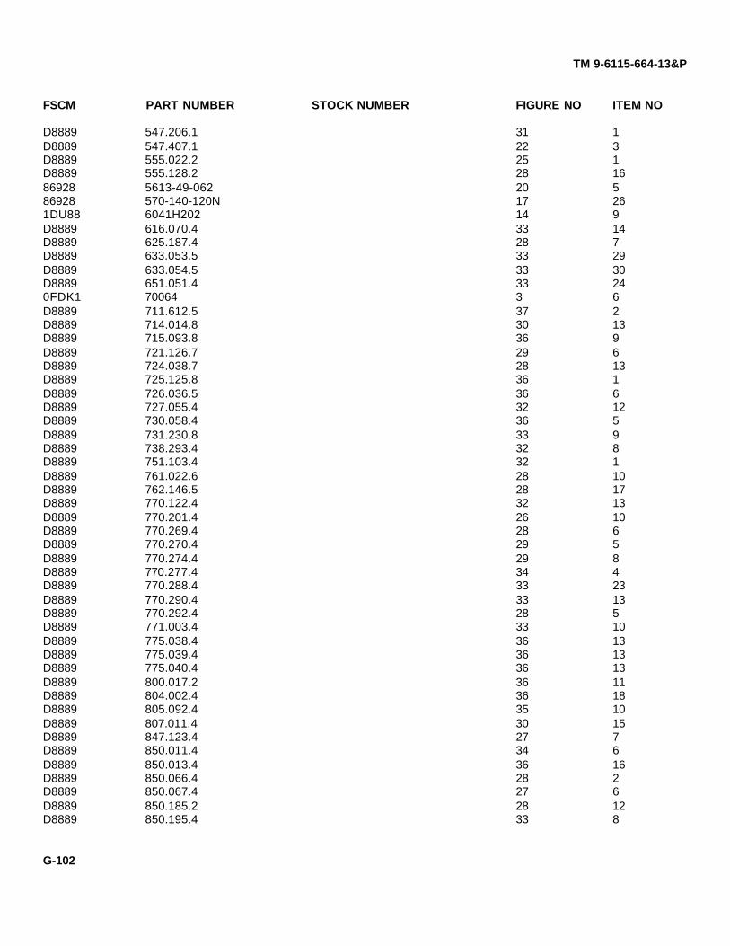
TM 9-6115-664-13&P
FSCM PART NUMBER STOCK NUMBER FIGURE NO ITEM NO
D8889 547.206.1 31 1D8889 547.407.1 22 3D8889 555.022.2 25 1D8889 555.128.2 28 1686928 5613-49-062 20 586928 570-140-120N 17 261DU88 6041H202 14 9D8889 616.070.4 33 14D8889 625.187.4 28 7D8889 633.053.5 33 29D8889 633.054.5 33 30D8889 651.051.4 33 240FDK1 70064 3 6D8889 711.612.5 37 2D8889 714.014.8 30 13D8889 715.093.8 36 9D8889 721.126.7 29 6D8889 724.038.7 28 13D8889 725.125.8 36 1D8889 726.036.5 36 6D8889 727.055.4 32 12D8889 730.058.4 36 5D8889 731.230.8 33 9D8889 738.293.4 32 8D8889 751.103.4 32 1D8889 761.022.6 28 10D8889 762.146.5 28 17D8889 770.122.4 32 13D8889 770.201.4 26 10D8889 770.269.4 28 6D8889 770.270.4 29 5D8889 770.274.4 29 8D8889 770.277.4 34 4D8889 770.288.4 33 23D8889 770.290.4 33 13D8889 770.292.4 28 5D8889 771.003.4 33 10D8889 775.038.4 36 13D8889 775.039.4 36 13D8889 775.040.4 36 13D8889 800.017.2 36 11D8889 804.002.4 36 18D8889 805.092.4 35 10D8889 807.011.4 30 15D8889 847.123.4 27 7D8889 850.011.4 34 6D8889 850.013.4 36 16D8889 850.066.4 28 2D8889 850.067.4 27 6D8889 850.185.2 28 12D8889 850.195.4 33 8
G-102

TM 9-6115-664-13&P
FSCM PART NUMBER STOCK NUMBER FIGURE NO ITEM NO
D8889 850.197.4 33 121DU88 8504K2 13 51DU88 8510K11 11 71DU88 8510K11 12 91DU88 8530K2 11 61DU88 8530K2 12 140ELG7 853009-16 24 3D8889 856.002.4 19 111DU88 8597K1 12 13D8889 861.096.2 37 4D8889 861.104.2 35 9D8889 890.02.09 30 2D8889 890.02.24 30 4D8889 890.08.01 30 17D8889 890.08.02 32 3D8889 890.10.03 29 4D8889 890.10.03 33 2D8889 890.10.05 33 19D8889 890.10.05 33 19D8889 890.10.07 32 11D8889 890.11.03 26 4D8889 890.11.03 27 3D8889 890.11.03 28 4D8889 890.11.03 33 25D8889 890.20.33 36 2D8889 890.24.02 28 11D8889 890.28.03 37 6D8889 890.28.14 26 12D8889 890.28.17 26 11D8889 890.28.32 33 15D8889 890.28.66 35 1D8889 890.31.07 28 3D8889 890.31.07 28 15D8889 890.31.08 28 8D8889 890.31.08 29 11D8889 890.31.10 29 1D8889 890.31.10 34 2D8889 890.31.11 29 2D8889 890.31.11 31 2D8889 890.31.28 26 3D8889 890.31.28 32 2D8889 890.31.28 32 14D8889 890.31.29 31 3D8889 890.31.90 36 8D8889 890.36.95 33 26D8889 890.37.20 33 18D8889 890.37.26 33 17D8889 890.38.03 27 2D8889 890.38.03 33 1D8889 890.38.05 26 7D8889 890.38.05 30 8
G-103

TM 9-6115-664-13&P
FSCM PART NUMBER STOCK NUMBER FIGURE NO ITEM NO
D8889 890.38.07 32 10D8889 890.38.07 33 21D8889 890.54.02 33 22D8889 890.59.51 32 7D8889 890.61.05 36 21D8889 890.66.03 30 9D8889 890.66.04 32 5D8889 890.67.05 33 27D8889 890.68.10 36 12D8889 890.74.04 33 6D8889 890.74.06 26 8D8889 890.74.06 27 5D8889 890.74.09 30 6D8889 890.74.11 28 21D8889 890.74.16 26 1D8889 890.74.17 28 18D8889 890.74.48 26 15D8889 890.74.48 35 5D8889 890.77.02 26 2D8889 890.77.06 26 18D8889 890.77.06 35 4D8889 890.78.02 28 14D8889 890.95.08 32 4D8889 890.95.10 29 9D8889 905.214.5 30 16D8889 905.220.5 30 10D8889 907.001.4 36 15D8889 911.004.4 32 60FDK1 913-1763 19 23D8889 917.287.4 29 7D8889 921.026.4 33 11D8889 922.010.4 26 5D8889 922.077.2 23 10D8889 923.892.4 23 11D8889 927.022.4 35 7D8889 928.093.4 33 33A054 9311K63 12 23A054 93620A905 11 183A054 93620A905 12 24D8889 945.009.4 26 9D8889 945.018.4 26 9D8889 945.036.4 26 96E876 94800A740 20 662502 96-9000 6115-01-452-6513 162502 96-9001 4 1462502 96-9002 2 1362502 96-9005 6 1862502 96-9006 6 1762502 96-9007 6 3162502 96-9008 6 16
G-104

TM 9-6115-664-13&P
FSCM PART NUMBER STOCK NUMBER FIGURE NO ITEM NO
62502 96-9009 6 2162502 96-9010 6 3362502 96-9011 6 1162502 96-9011 6 4562502 96-9012 6 262502 96-9013 6 1362502 96-9013 6 3462502 96-9014 6 4262502 96-9017 6 562502 96-9017 6 3962502 96-9018 6 462502 96-9018 6 3862502 96-9019 6 4062502 96-9020 6 162502 96-9027 6 4962502 96-9028 6 962502 96-9029 6 1562502 96-9031 1 762502 96-9032 6 762502 96-9032 6 3862502 96-9033 6 662502 96-9035 4 1862502 96-9038 5 962502 96-9038 8 862502 96-9039 5 262502 96-9040 5 462502 96-9041 5 562502 96-9042 5 1162502 96-9045 7 1962502 96-9050 8 162502 96-9060 9 662502 96-9065 9 362502 96-9066 10 162502 96-9069 10 862502 96-9070 10 362502 96-9071 10 762502 96-9075 2 1262502 96-9076 2 562502 96-9077 2 962502 96-9077 8 1662502 96-9079 7 162502 96-9083 7 2062502 96-9089 7 1462502 96-9092 8 662502 96-9094 8 2462502 96-9095 7 2262502 96-9096 9 162502 96-9097 8 2562502 96-9098 5 3
G-105

TM 9-6115-664-13&P
FSCM PART NUMBER STOCK NUMBER FIGURE NO ITEM NO
62502 96-9098 7 562502 96-9099 7 462502 96-9100 1 662502 96-9101 1 462502 96-9102 1 362502 96-9103 1 862502 96-9104 1 962502 96-9105 1 1062502 96-9106 7 3062502 96-9111 8 1962502 96-9112 8 1162502 96-9114 7 1662502 96-9116 7 1262520 96-9120 7 3362520 96-9122 4 2362502 96-9124 8 1762502 96-9129 1 562502 96-9130 1 1462502 96-9131 1 1662502 96-9145 8 2262502 96-9150 4 2262502 96-9151 13 162502 96-9156-1 13 862502 96-9156-2 13 662502 96-9156-3 13 762502 96-9157 13 2462502 96-9158-3 13 2162502 96-9158-3 17 2862502 96-9158-4 13 2262502 96-9158-4 17 2762502 96-9160 13 962502 96-9166-1 13 3062502 96-9166-2 15 162502 96-9166-3 14 462502 96-9166-4 16 1562502 96-9166-5 23 862502 96-9166-6 23 562502 96-9166-7 16 1162502 96-9166-8 13 2862502 96-9170 14 562502 96-9175 14 362502 96-9179 16 362502 96-9180 16 462502 96-9191 13 1962502 96-9196 14 1062502 96-9202 13 3762502 96-9203 14 1262502 96-9204 14 762502 96-9205 13 262502 96-9222 3 16
G-106

TM 9-6115-664-13&P
FSCM PART NUMBER STOCK NUMBER FIGURE NO ITEM NO
62502 96-9223 3 2062502 96-9224 3 1562502 96-9226 3 1962502 96-9227 3 1862502 96-9228 3 2162502 96-9229 3 562502 96-9229 3 1062502 96-9235 3 162502 96-9240 3 20VKD6 96-9247-3 21 60VKD6 96-9247-4 20 90VKD6 96-9247-5 19 60VKD6 96-9247-5 19 90VKD6 96-9247-5 21 30VKD6 96-9247-5 38 140VKD6 96-9247-6 4 20VKD6 96-9247-6 17 230VKD6 96-9248-3 21 50VKD6 96-9248-4 20 100VKD6 96-9248-5 19 70VKD6 96-9248-5 19 100VKD6 96-9248-5 21 40VKD6 96-9248-6 17 240VKD6 96-9249-029-SH 21 70VKD6 96-9249-056-FH 22 90VKD6 96-9249-084-HH 19 50VKD6 96-9249-084-HH 21 20VKD6 96-9249-090-HH 38 130VKD6 96-9249-092-HH 19 80VKD6 96-9249-103-HH 17 2262502 96-9249-105-SH 17 190VKD6 96-9249-125SH-S 4 40VKD6 96-9249-128SH-S 4 362502 96-9250 4 562502 96-9251 19 1362502 96-9252 17 362502 96-9253 17 262502 96-9257 23 462502 96-9261 4 662502 96-9266 17 2162502 96-9267 17 2562502 96-9268 17 2062502 96-9270 17 462502 96-9275 18 462502 96-9277 17 762502 96-9278 17 662502 96-9279 17 1362502 96-9282 18 762502 96-9283 18 1162502 96-9284 18 9
G-107

TM 9-6115-664-13&P
FSCM PART NUMBER STOCK NUMBER FIGURE NO ITEM NO
62502 96-9285 17 1862502 96-9292 38 262502 96-9293 38 1262502 96-9295 38 462502 96-9305 17 162502 96-9307 38 862502 96-9309 20 462502 96-9310 20 362502 96-9312 20 1262502 96-9314 20 1162502 96-9315 20 1662502 96-9316 20 1562502 96-9317 20 262502 96-9325 19 1962502 96-9326 19 2062502 96-9327 19 2562502 96-9330 19 2262502 96-9340 21 162502 96-9344 19 162502 96-9345 19 262502 96-9352 19 1762502 96-9355 19 462502 96-9362 24 162502 96-9364 24 462502 96-9366 24 1262502 96-9376-04 11 2262502 96-9390 1 262502 96-9392 1 162502 96-9404 12 2362502 96-9412 12 1962502 96-9422 12 2262502 96-9425 12 40VKD6 96-9429-058-HH 20 80VKD6 96-9429-49 17 562502 96-9430 12 362502 96-9431 12 762502 96-9433 12 1062502 96-9440 4 2262502 96-9450 11 1062502 96-9453 11 462502 96-9453-1 11 962502 96-9461 11 2062502 96-9462 11 1662502 96-9464 11 21D8889 971.481.5 26 6D8889 971.495.5 23 13D8889 971.496.5 33 7D8889 973.028.5 26 16D8889 982.334.4 25 2
G-108

TM 9-6115-664-13&P
NATIONAL STOCK NUMBER INDEX
STOCK NUMBER FIGURE ITEM STOCK NUMBER FIGURE ITEM
4730-00-014-4027 16 9 5310-00-616-2200 3 125310-00-045-3296 4 12 5310-00-616-2200 4 165310-00-045-3296 7 11 5310-00-619-4848 2 75310-00-045-3296 9 8 5310-00-619-4848 7 285310-00-045-3296 13 4 5310-00-619-4848 10 45310-00-045-3296 16 2 5310-00-619-4848 17 115310-00-045-3296 17 16 5310-00-637-9541 6 295310-00-045-3296 18 6 5310-00-637-9541 9 105305-00-068-0502 10 5 5310-00-637-9541 38 65305-00-071-2072 38 9 5310-00-641-9464 2 45305-00-071-2237 12 1 5310-00-641-9464 3 115925-00-074-9180 11 23 5310-00-641-9464 4 175305-00-115-9526 9 16 5310-00-641-9464 5 75305-00-115-9526 23 3 5310-00-641-9464 6 265305-00-115-9526 38 7 5310-00-641-9464 6 305310-00-167-0766 12 5 5310-00-641-9464 7 75310-00-167-0766 14 11 5310-00-641-9464 9 95310-00-167-0818 3 2 5310-00-641-9464 38 55310-00-167-0818 4 8 5930-00-681-4394 12 265310-00-167-0818 4 11 5930-00-729-8108 22 15310-00-167-0818 8 3 5310-00-809-3078 4 215310-00-167-0818 9 4 5310-00-809-3078 9 145310-00-167-0818 11 2 5310-00-809-5997 1 135310-00-167-0818 17 9 5310-00-809-5997 2 25310-00-167-0818 17 17 5310-00-809-5997 6 235310-00-167-0818 18 1 5310-00-809-5997 38 115305-00-225-3839 4 19 5310-00-877-5798 4 125305-00-225-3839 8 13 5310-00-877-5798 3 155305-00-225-3839 14 8 5310-00-877-5798 4 75305-00-225-3839 20 17 5310-00-877-5798 8 45306-00-225-8499 4 19 5310-00-877-5798 9 55305-00-226-4831 6 28 5310-00-877-5798 11 255305-00-269-3211 6 32 5310-00-877-5798 17 145305-00-269-3211 9 11 5310-00-877-5798 18 85305-00-269-3218 3 14 5305-00-958-5471 3 134730-00-277-2448 13 25 5305-00-978-9381 7 255305-00-406-6695 16 1 5305-00-983-7470 7 185310-00-407-9566 3 8 5305-00-984-4983 11 175310-00-407-9566 4 20 5305-00-984-4983 12 255310-00-407-9566 9 15 5305-00-984-4992 11 114730-00-427-5121 16 7 5305-00-984-4992 12 205305-00-543-2419 2 11 5305-00-984-7361 13 35305-00-543-2419 3 13 5305-00-988-1727 6 35305-00-543-2419 4 15 5305-00-988-1727 6 365305-00-543-2419 5 6 5305-00-989-7343 4 105305-00-543-2419 7 8 5305-00-989-7434 7 105310-00-582-5965 4 20 5305-00-989-7434 9 75310-00-582-5965 8 14 5305-00-989-7434 13 55310-00-584-5272 1 12 5305-00-989-7434 18 55310-00-584-5272 38 10 5305-00-990-1347 2 6
5305-00-993-1848 7 35305-00-993-1848 8 18
G-109

TM 9-6115-664-13&P
STOCK NUMBER FIGURE ITEM STOCK NUMBER FIGURE ITEM
5305-00-993-1848 9 18 5342-01-163-1299 13 165305-00-993-1848 11 1 5305-01-325-8388 2 15305-00-993-1848 12 16 5305-01-351-0787 3 175305-00-993-1848 13 18 5950-01-388-0744 9 175305-00-993-1848 17 15 5310-01-398-0341 4 215305-00-993-1848 18 2 5310-01-398-0341 8 155305-00-993-1851 4 13 5310-01-398-0341 13 325305-00-993-1851 7 18 5310-01-398-0341 14 25305-00-993-1851 8 2 5310-01-398-0341 20 144730-01-096-3170 13 33 6115-01-452-6513 15935-01-097-9974 7 95935-01-097-9974 13 20
G-110

TM 9-6115-664-13&P
FIGURE AND ITEM NUMBER INDEX
FIGURE NO ITEM NO STOCK NUMBER FSCM PART NUMBER
1 6115-01-452-6513 62502 96-90001 1 62502 96-93921 2 62502 96-93901 3 62502 96-91021 4 62502 96-91011 5 62502 96-91291 6 62502 96-91001 7 62502 96-90311 8 62502 96-91031 9 62502 96-91041 10 62502 96-91051 11 96906 MS35307-4131 12 5310-00-584-5272 96906 MS35338-481 13 5310-00-809-5997 96906 MS27183-171 14 62502 96-91301 15 D8889 110.116.51 16 62502 96-91312 1 5305-01-325-8388 96906 MS90725-1132 2 5310-00-809-5997 96906 MS27183-172 3 96906 MS17829-6C2 4 5310-00-641-9464 96906 MS27183-132 5 62502 96-90762 6 5305-00-990-1347 96906 MS35190-2922 7 5310-00-619-4848 96906 MS27183-512 8 96906 MS27189-4C2 9 62502 96-90772 10 96906 MS17829-8C2 11 5305-00-543-2419 96906 MS90725-612 12 62502 96-90752 13 62502 96-90023 1 62502 96-92353 2 62502 96-92403 3 22165 105CFH1-83 4 96906 MS35842-143 5 62502 96-92293 6 0FDK1 700643 7 96906 MS35842-143 8 5310-00-407-9566 96906 MS35338-453 9 96906 MS16997-823 10 62502 96-92293 11 5310-00-641-9464 96906 MS27183-133 12 5310-00-616-2200 96906 MS35337-463 13 5305-00-543-2419 96906 MS90725-613 14 5305-00-269-3218 96906 MS90725-683 15 5310-00-877-5798 96906 MS21044-D33 16 62502 96-9222
G-111

TM 9-6115-664-13&P
FIGURE NO ITEM NO STOCK NUMBER FSCM PART NUMBER
3 17 5305-01-351-0787 96906 MS90725-733 18 62502 96-92273 19 62502 96-92263 20 62502 96-92233 21 62502 96-92284 1 0AKY4 C5506X64 2 0VKD6 96-9247-64 3 0VKD6 96-9249-128SH-S4 4 0VKD6 96-9249-125SH-S4 5 62502 96-92504 6 62502 96-92614 7 5310-00-877-5798 96906 MS21044-D34 8 5310-00-167-0818 88044 AN960-104 9 96906 MS21919-124 10 5305-00-989-7343 96906 MS35191-2764 11 5310-00-167-0818 88044 AN960-104 12 5310-00-045-3296 96906 MS35338-434 13 5305-00-993-1851 96906 MS35207-2674 14 62502 96-90014 15 5305-00-543-2419 96906 MS90725-614 16 5310-00-616-2200 96906 MS35337-464 17 5310-00-641-9464 96906 MS27183-134 18 62502 96-90354 19 5305-00-225-3839 96906 MS90725-84 20 5310-00-582-5965 96906 MS35338-444 21 5310-01-398-0341 80205 NAS1149G0432P4 22 62502 96-94404 23 5306-00-225-8499 96906 MS90725-344 24 5310-00-407-9566 96906 MS35338-454 25 5310-00-809-3078 96906 MS27183-114 26 62502 96-91504 27 62520 96-91225 1 F9948 101-301-1915 2 62502 96-90395 3 62502 96-90985 4 62502 96-90405 5 62502 96-90415 6 5305-00-543-2419 96906 MS90725-615 7 5310-00-641-9464 96906 MS27183-135 8 19220 1170-25 9 62502 96-90385 10 96906 MS17829-6C5 11 62502 96-90425 12 19220 1170-36 1 62502 96-90206 2 62502 96-90126 3 5305-00-988-1727 96906 MS35206-2836 4 62502 96-90186 5 62502 96-9017
G-112

TM 9-6115-664-13&P
FIGURE NO ITEM NO STOCK NUMBER FSCM PART NUMBER
6 6 62502 96-90336 7 62502 96-90326 8 96906 MS35191-3036 9 62502 96-90286 10 88044 AN565-1032-66 11 62502 96-90116 12 88044 AN565-416-206 13 62502 96-90136 14 F9948 101-301-1916 15 62502 96-90296 16 62502 96-90086 17 62502 96-90066 18 62502 96-90056 19 9X737 B40R6 20 96906 MS16997-846 21 62502 96-90096 22 96906 MS17829-4C6 23 5310-00-809-5997 96906 MS51859-176 24 96906 MS90725-266 25 96906 MS17829-6C6 26 5310-00-641-9464 96906 MS27183-136 27 F9948 101-301-1916 28 5305-00-226-4831 96906 MS90725-386 29 5310-00-637-9541 96906 MS35338-466 30 5310-00-641-9464 96906 MS27183-136 31 62502 96-90076 32 5305-00-269-3211 96906 MS90725-606 33 62502 96-90106 34 62502 96-90136 35 54836 10-4855-AU6 36 5305-00-988-1727 96906 MS35206-2836 37 62502 96-90196 38 62502 96-90326 39 62502 96-90176 40 62502 96-90186 41 96906 MS35191-3036 42 62502 96-90146 43 F9948 101-301-1916 44 88044 AN565-416-206 45 62502 96-90116 46 88044 AN565-1032-66 47 3A054 3896T16 48 3A05A 3458T446 49 62502 96-90277 1 62502 96-90797 2 5310-00-167-0818 88044 AN960-107 3 5305-00-993-1848 96906 MS35207-2657 4 62502 96-90997 5 62502 96-9098
G-113

TM 9-6115-664-13&P
FIGURE NO ITEM NO STOCK NUMBER FSCM PART NUMBER
7 6 0DG59 17/1600/17 7 5310-00-641-9464 96906 MS27183-137 8 5305-00-543-2419 96906 MS90725-617 9 5935-01-097-9974 19207 116747287 10 5305-00-989-7434 96906 MS35207-2637 11 5310-00-045-3296 96906 MS35338-437 12 62502 96-91167 13 96906 MS35190-2737 14 62502 96-90897 15 96906 MS21044-D37 16 62502 96-91147 17 5305-00-983-7470 96906 MS16997-1537 18 5305-00-993-1851 96906 MS35207-2677 19 62502 96-90457 20 62502 96-90837 21 96906 MS17829-6C7 22 62502 96-90957 23 62520 96-91207 24 F9948 101-301-1917 25 5305-00-978-9381 96906 MS16997-637 26 04EE5 10-4B SSN7 27 96906 MS17829-4C7 28 5310-00-619-4848 96906 MS27183-517 29 07851 W0367-0067 30 62502 96-91067 31 96906 MS27183-437 32 96906 MS35206-2327 33 62502 280142067 34 96906 MS21044-D37 35 96906 MS35207-2617 36 13445 30172-157 37 96906 MS21044N067 38 74440 850947 39 62502 96-9359-18 1 62502 96-90508 2 5305-00-993-1851 96906 MS35207-2678 3 5310-00-167-0818 88044 AN960-108 4 5310-00-877-5798 96906 MS21044-D38 5 96906 MS35190-3198 6 62502 96-90928 7 19220 1170-38 8 62502 96-90388 9 19220 1170-28 10 96906 MS17829-6C8 11 62502 96-91128 12 96906 MS35190-3228 13 5305-00-225-3839 96906 MS90725-88 14 5310-00-582-5965 96906 MS35338-448 15 5310-01-398-0341 80205 NAS1149G0432P8 16 62502 96-90778 17 62502 96-91248 18 5305-00-993-1848 96906 MS35207-265
G-114

TM 9-6115-664-13&P
FIGURE NO ITEM NO STOCK NUMBER FSCM PART NUMBER
8 19 62502 96-91118 20 0ATZ6 3706T1318 21 0ATZ6 11355T298 22 62502 96-91458 23 0ATZ6 29695T918 24 62502 96-90948 25 62502 96-90979 1 62502 96-90969 2 F9948 101-301-1919 3 62502 96-90659 4 5310-00-167-0818 88044 AN960-109 5 5310-00-877-5798 96906 MS21044-D39 6 62502 96-90609 7 5305-00-989-7434 96906 MS35207-2639 8 5310-00-045-3296 96906 MS35338-439 9 5310-00-641-9464 96906 MS27183-139 10 5310-00-637-9541 96906 MS35338-469 11 5305-00-269-3211 96906 MS90725-609 12 62502 3010.03799 13 62502 3013.00329 14 5310-00-809-3078 96906 MS27183-119 15 5310-00-407-9566 96906 MS35338-459 16 5305-00-115-9526 96906 MS90725-589 17 5950-01-388-0744 34899 04431672519 18 5305-00-993-1848 96906 MS35207-26510 1 62502 96-906610 2 62502 2196-S10 3 62502 96-907010 4 5310-00-619-4848 96906 MS27183-5110 5 5305-00-068-0502 96906 MS16997-6010 6 0AKY4 24306E-606-66610 7 62502 96-907110 8 62502 96-906910 9 50184 ICS10412X-12RB9C
AMXS-S-021011 1 5305-00-993-1848 96906 MS35207-26511 2 5310-00-167-0818 88044 AN960-1011 3 96906 MS34338-4311 4 62502 96-945311 5 1DU88 2TL1-50M11 6 1DU88 8530K211 7 1DU88 8510K1111 8 1DU88 1TL1-311 9 62502 96-9453-111 10 62502 96-945011 11 5305-00-984-4992 96906 MS35206-23211 12 96906 MS21004-N0811 13 13074 5015111 14 5310-00-877-5798 96906 MS21044-D311 15 19328 205111 16 62502 96-946211 17 5305-00-984-4983 96906 MS35206-226
G-115
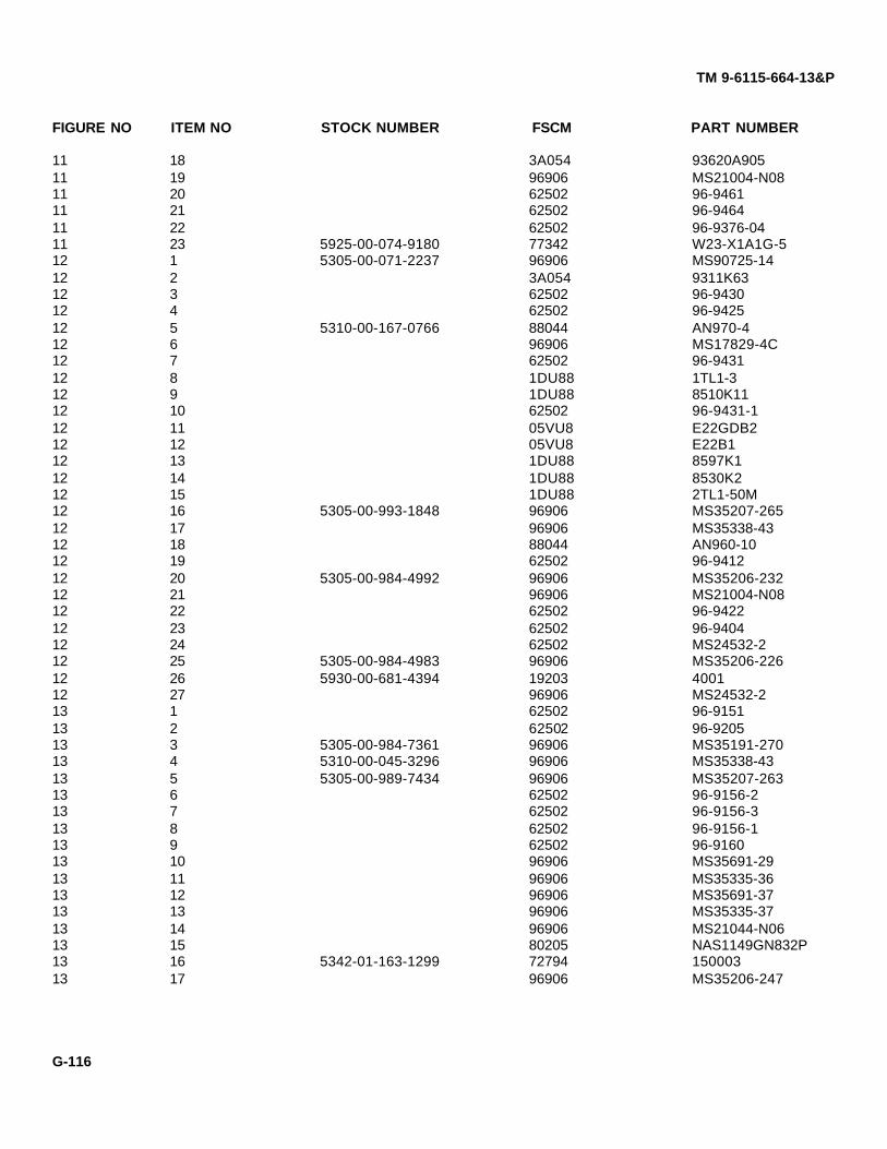
TM 9-6115-664-13&P
FIGURE NO ITEM NO STOCK NUMBER FSCM PART NUMBER
11 18 3A054 93620A90511 19 96906 MS21004-N0811 20 62502 96-946111 21 62502 96-946411 22 62502 96-9376-0411 23 5925-00-074-9180 77342 W23-X1A1G-512 1 5305-00-071-2237 96906 MS90725-1412 2 3A054 9311K6312 3 62502 96-943012 4 62502 96-942512 5 5310-00-167-0766 88044 AN970-412 6 96906 MS17829-4C12 7 62502 96-943112 8 1DU88 1TL1-312 9 1DU88 8510K1112 10 62502 96-9431-112 11 05VU8 E22GDB212 12 05VU8 E22B112 13 1DU88 8597K112 14 1DU88 8530K212 15 1DU88 2TL1-50M12 16 5305-00-993-1848 96906 MS35207-26512 17 96906 MS35338-4312 18 88044 AN960-1012 19 62502 96-941212 20 5305-00-984-4992 96906 MS35206-23212 21 96906 MS21004-N0812 22 62502 96-942212 23 62502 96-940412 24 62502 MS24532-212 25 5305-00-984-4983 96906 MS35206-22612 26 5930-00-681-4394 19203 400112 27 96906 MS24532-213 1 62502 96-915113 2 62502 96-920513 3 5305-00-984-7361 96906 MS35191-27013 4 5310-00-045-3296 96906 MS35338-4313 5 5305-00-989-7434 96906 MS35207-26313 6 62502 96-9156-213 7 62502 96-9156-313 8 62502 96-9156-113 9 62502 96-916013 10 96906 MS35691-2913 11 96906 MS35335-3613 12 96906 MS35691-3713 13 96906 MS35335-3713 14 96906 MS21044-N0613 15 80205 NAS1149GN832P13 16 5342-01-163-1299 72794 15000313 17 96906 MS35206-247
G-116

TM 9-6115-664-13&P
FIGURE NO ITEM NO STOCK NUMBER FSCM PART NUMBER
13 18 5305-00-993-1848 96906 MS35207-26513 19 62502 96-919t13 20 5935-01-097-9974 19207 1167472813 21 62502 96-9158-313 22 62502 96-9158-413 23 96906 MS21044-N313 24 62502 96-915713 25 4730-00-277-2448 79470 C5405X4X413 26 96906 MS35190-29113 27 0AKY4 3169X413 28 62502 96-9166-813 29 2L549 3326013 30 62502 96-9166-113 31 96906 MS17829-4C13 32 5310-01-398-0341 80205 NAS1149G0432P13 33 4730-01-096-3170 96906 C5405X5X413 34 62502 96-920214 1 96906 MS17829-4C14 2 5310-01-398-0341 80205 NAS1149G0432P14 3 62502 96-917514 4 62502 96-9166-314 5 62502 96-917014 6 80205 NAS1515F4H14 7 62502 96-920414 8 5305-00-225-3839 96906 MS90725-814 9 1DU88 6041H20214 10 62502 96-919614 11 5310-00-167-0766 88044 AN970-414 12 62502 96-920314 13 96906 MS35190-29115 1 62502 96-9166-215 2 0L4R8 3-520117-215 3 0L4R8 3-520107-215 4 0AKY4 C5205X415 5 71425 E101216 1 5305-00-406-6695 96906 MS35206-33716 2 5310-00-045-3296 96906 MS35338-4316 3 62502 96-917916 4 62502 96-918016 5 03479 1505052716 6 03479 1500016216 7 4730-00-427-5121 79470 3152X616 8 03479 1505052516 9 4730-00-014-4027 79470 3152X816 10 0AKY4 C5525X516 11 62502 96-9166-716 12 0BT82 1637-02580016 13 0AKY4 32206X6X216 14 0AKY4 C5405X516 15 62502 96-9166-416 16 03479 15050526
G-117

TM 9-6115-664-13&P
FIGURE NO ITEM NO STOCK NUMBER FSCM PART NUMBER
16 17 03479 1500015916 18 0AKY4 C5525X417 1 62502 96-930517 2 62502 96-925317 3 62502 96-925217 4 0VKD6 96-9429-05617 5 62502 96-927017 6 62502 96-927817 7 62502 96-927717 8 96906 MS35207-26517 9 5310-00-167-0818 88044 AN960-1017 10 96906 MS16997-6417 11 5310-00-619-4848 96906 MS27183-5117 12 96906 MS17829-4C17 13 62502 96-927917 14 5310-00-877-5798 96906 MS21044-D317 15 5305-00-993-1848 96906 MS35207-26517 16 5310-00-045-3296 96906 MS35338-4317 17 5310-00-167-0818 88044 AN960-1017 18 62502 96-928517 19 62502 96-9249-105-SH17 20 62502 96-926817 21 62502 96-926617 22 0VKD6 96-9249-103-HH17 23 0VKD6 96-9247-617 24 0VKD6 96-9248-617 25 62502 96-926717 26 86928 570-140-120N17 27 62502 96-9158-417 28 62502 96-9158-317 29 0VKD6 96-9248-418 1 5310-00-167-0818 88044 AN960-1018 2 5305-00-993-1848 96906 MS35207-26518 3 76761 N312918 4 62502 96-927518 5 5305-00-989-7434 96906 MS35207-26318 6 5310-00-045-3296 96906 MS35338-4318 7 62502 96-928218 8 07851 AD44AH18 9 62502 96-928418 10 96906 MS521059-318 11 62502 96-928318 12 5310-00-877-5798 96906 MS21044-D318 13 07851 GAMD34A19 1 62502 96-934419 2 62502 96-934519 3 88044 AN530-2-419 4 62502 96-935519 5 0VKD6 96-9249-084-HH
G-118

TM 9-6115-664-13&P
FIGURE NO ITEM NO STOCK NUMBER FSCM PART NUMBER
19 6 0VKD6 96-9247-519 7 0VKD6 96-9248-519 8 0VKD6 96-9249-092-HH19 9 0VKD6 96-9247-519 10 0VKD6 96-9248-519 11 D8889 856.002.419 12 D8889 440.064.419 13 62502 96-925119 14 D8889 43F19 15 D8889 541.050.2E19 16 06YT7 181SN19 17 62506 96-935219 18 0AKY4 C5355X6X619 19 62502 96-932519 20 62502 96-932619 21 C4519 191253139H19 22 62502 96-933019 23 0FDK1 913-176319 24 12088 PC501B19 25 62502 96-932720 1 96906 MS35842-1220 2 62502 96-931720 3 62502 96-931020 4 62502 96-930920 5 86928 5613-49-06220 6 6E876 94800A74020 7 4Z382 CA630620 8 0VKD6 96-9429-058-HH20 9 0VKD6 96-9247-420 10 0VKD6 96-9248-420 11 62502 96-931420 12 62502 96-931220 13 96906 MS17829-4C20 14 5310-01-398-0341 80205 NAS1149G0432P20 15 62502 96-931620 16 62502 96-931520 17 5305-00-225-3839 96906 MS90725-821 1 62502 96-934021 2 0VKD6 96-9249-084-HH21 3 0VKD6 96-9247-521 4 0VKD6 96-9248-521 5 0VKD6 96-9248-321 6 0VKD6 96-9247-321 7 0VKD6 96-9249-029-SH21 8 96906 MS35207-26721 9 88044 AN960-1021 10 96906 MS35338-4322 1 5930-00-729-8108 81640 W101622 2 D8889 547.407.122 3 D8889 890.08.0222 4 D8889 890.3 8.03
G-119

TM 9-6115-664-13&P
FIGURE NO ITEM NO STOCK NUMBER FSCM PART NUMBER
22 5 D8889 555.164.222 6 D8889 890.37.0922 7 D8889 923.931.422 8 0VKD6 96-9249-056-FH22 9 D8889 890.10.0323 1 96906 MS3367-523 2 80205 NAS1149G0632P23 3 5305-00-115-9526 96906 MS90725-5823 4 62502 96-925723 5 62502 96-9166-623 6 0AKY4 C5506X523 7 0AKY4 C5506X423 8 62502 96-9166-523 9 96906 MS17829-6C23 10 D8889 922.077.223 11 D8889 923.892.423 12 D8889 541.038.223 13 D8889 971.495.524 1 62502 96-936224 2 62502 96-936624 3 0ELG7 853009-1624 4 62502 96-936425 1 D8889 555.022.225 2 D8889 982.334.425 3 D8889 515.103.425 4 D8889 238.018.226 1 D8889 890.74.1626 2 D8889 890.77.0226 3 D8889 890.31.2826 4 D8889 890.11.0326 5 D8889 922.010.426 6 D8889 971.481.526 7 D8889 890.38.0526 8 D8889 890.74.0626 9 D8889 945.009.426 9 D8889 945.018.426 9 D8889 945.036.426 10 D8889 770.201.426 11 D8889 890.28.1726 12 D8889 890.28.1426 13 D8889 536.306.226 14 D8889 971.482.526 15 D8889 890.74.4826 16 D8889 973.028.526 17 D8889 890.77.0626 18 D8889 536.033.126 19 D8889 536.219.226 20 D8889 536.307.226 21 D8889 536.308.226 22 D8889 536.305.227 1 D8889 175.078.127 2 D8889 890.38.03
G-120

TM 9-6115-664-13&P
FIGURE NO ITEM NO STOCK NUMBER FSCM PART NUMBER
27 3 D8889 890.11.0327 4 D8889 515.357.227 5 D8889 890.74.0627 6 D8889 850.067.427 7 D8889 847.123.428 1 D8889 509.040.428 2 D8889 850.066.428 3 D8889 890.31.0728 4 D8889 890.11.0328 5 D8889 770.292.428 6 D8889 770.269.428 7 D8889 625.187.428 8 D8889 890.31.0828 9 D8889 237.027.228 10 D8889 761.022.628 11 D8889 890.24.0228 12 D8889 850.185.228 13 D8889 724.038.728 14 D8889 890.78.0228 15 D8889 890.31.0728 16 D8889 555.128.228 17 D8889 762.146.528 18 D8889 890.74.1728 19 D8889 E860.343.528 20 D8889 E761.016.828 21 D8889 890.74.1129 1 D8889 890.31.1029 2 D8889 890.31.1129 3 D8889 512.094.429 4 D8889 890.10.0329 5 D8889 770.270.429 6 D8889 721.126.729 7 D8889 917.287.429 8 D8889 770.274.429 9 D8889 890.95.1029 10 D8889 118.127.429 11 D8889 890.31.0830 1 D8889 514.096.230 2 D8889 890.02.0930 3 D8889 465.177.430 4 D8889 890.02.2430 5 D8889 508.019.430 6 D8889 890.74.0930 7 D8889 514.105.430 8 D8889 890.38.0530 9 D8889 890.66.0330 10 D8889 905.220.530 11 D8889 521.009.430 12 D8889 E722.074.830 13 D8889 714.014.8
G-121

TM 9-6115-664-13&P
FIGURE NO ITEM NO STOCK NUMBER FSCM PART NUMBER
30 14 D8889 415.153.430 15 D8889 807.011.430 16 D8889 905.214.530 17 D8889 890.08.0130 18 D8889 514.097.231 1 D8889 547.206.131 2 D8889 890.31.1131 3 D8889 890.31.2931 4 D8889 547.070.232 1 D8889 751.103.432 2 D8889 890.31.2832 3 D8889 890.08.0232 4 D8889 890.95.0832 5 D8889 890.66.0432 6 D8889 911.004.432 7 D8889 890.59.5132 8 D8889 738.293.432 9 D8889 453.002.432 10 D8889 890.38.0732 11 D8889 890.10.0732 12 D8889 727.055.432 13 D8889 770.122.432 14 D8889 890.31.2832 15 D8889 890.08.0232 16 D8889 522.019.433 1 D8889 890.38.0333 2 D8889 890.10.0333 3 D8889 928.093.433 4 D8889 537.015.133 5 D8889 515.353.233 6 D8889 890.74.0433 7 D8889 971.496.533 8 D8889 850.195.433 9 D8889 731.230.833 10 D8889 771.003.433 11 D8889 921.026.433 12 D8889 850.197.433 13 D8889 770.290.433 14 D8889 616.070.433 15 D8889 890.28.3233 16 D8889 514.104.233 17 D8889 890.37.2633 18 D8889 890.37.2033 19 D8889 890.10.0533 19 D8889 890.10.0533 20 D8889 522.022.433 21 D8889 890.38.0733 22 D8889 890.54.02
G-122

TM 9-6115-664-13&P
FIGURE NO ITEM NO STOCK NUMBER FSCM PART NUMBER
33 23 D8889 770.288.433 24 D8889 651.051.433 25 D8889 890.11.0333 26 D8889 890.36.9533 27 D8889 890.67.0533 28 D8889 415.156.433 29 D8889 633.053.533 30 D8889 633.054.534 1 D8889 421.069.434 2 D8889 890.31.1034 3 D8889 424.021.434 4 D8889 770.277.434 5 D8889 423.022.434 6 D8889 850.011.434 7 D8889 421.070.435 1 D8889 890.28.6635 2 D8889 427.043.435 3 D8889 427.044.435 4 D8889 890.77.0635 5 D8889 890.74.4835 6 D8889 426.032.435 7 D8889 927.022.435 8 D8889 426.031.435 9 D8889 861.104.235 10 D8889 805.092.435 11 D8889 531.009.435 12 D8889 E527.007.236 1 D8889 725.125.836 2 D8889 890.20.3336 3 D8889 418.017.436 4 D8889 535.143.136 5 D8889 730.058.436 6 D8889 726.036.536 7 D8889 465.169.436 8 D8889 890.31.9036 9 D8889 715.093.836 10 D8889 470.022.436 10 D8889 470.023.436 10 D8889 470.024.436 11 D8889 800.017.236 12 D8889 890.68.1036 13 D8889 775.038.436 13 D8889 775.039.436 13 D8889 775.040.436 14 D8889 452.134.436 15 D8889 907.001.436 16 D8889 850.013.436 17 D8889 519.038.4
G-123

TM 9-6115-664-13&P
FIGURE NO ITEM NO STOCK NUMBER FSCM PART NUMBER
36 18 D8889 804.002.436 19 D8889 514.001.436 20 D8889 540.051.136 21 D8889 890.61.0537 1 D8889 512.006.437 2 D8889 711.612.537 3 D8889 512.113.437 4 D8889 861.096.237 5 D8889 4658.006.437 6 D8889 890.28.0338 1 76761 N137938 2 62502 96-929238 3 88044 AN565928-638 4 62502 96-929538 5 5310-00-641-9464 96906 MS27183-1338 6 5310-00-637-9541 96906 MS35338-4638 7 5305-00-115-9526 96906 MS90725-5838 8 62502 96-930738 9 5305-00-071-2072 80204 MS90725-11638 10 5310-00-584-5272 96906 MS35338-4838 11 5310-00-809-5997 96906 MS27183-1738 12 62502 96-929338 13 0VKD6 96-9249-090-HH38 14 0VKD6 96-9247-538 15 D8889 415.079.4
G-124

TM 9-6115-664-13&P
APPENDIX H
TORQUE LIMITS
Section I. INTRODUCTION
H-1. Scope.
This appendix lists torque ratings for fasteners used on the APU. When torque values are called out in themaintenance procedures, those torques supersede the torques specified in this appendix. Table H-1 lists torque limits forstandard fasteners installed dry. Table H-2 provides formulas for converting the dry torque values to wet. Table H-3 liststorque limits for standard metric fasteners installed dry.
Section II. TORQUE LIMITS
Table H-1. Torque Limits for Dry Fasteners
TORQUESIZE
SAE GRADE 0-1-2 SAE GRADE 3 SAE GRADE 5
Diameter in Threads Per Millimeters Foot Newton Foot Newton Foot NewtonInches Inch Pounds Meters Pounds Meters Pounds Meters
1/4 20 6.350 6 8 9 12 10 141/4 28 6.350 7 9 10 13 11 155/16 18 7 937 12 16 17 23 19 265/16 24 7 937 13 18 18 25 21 283/8 16 9.525 20 27 30 40 33 453/8 24 9 525 22 30 33 44 36 497/16 14 11.112 32 43 47 64 54 737/16 20 11.112 35 47 51 69 59 801/2 13 12.700 47 64 69 93 78 1061/2 20 12.700 51 69 75 102 85 1159/16 12 14.287 69 94 103 140 114 1559/16 18 14.287 75 102 112 152 124 1685/8 11 15.875 96 130 145 197 154 2095/8 28 15.875 105 142 158 214 168 2283/4 10 19.050 155 210 234 317 257 3483/4 26 19.050 169 229 255 346 280 3807/8 9 22.225 206 279 372 504 382 5187/8 24 22.225 225 304 405 550 416 5651 8 25.400 310 420 551 747 587 7961 14 25.400 338 458 601 814 640 867
See Table H-2 for the effect of lubrication on torque.
H-1

TM 9-6115-664-13&P
Table H-1. Torque Limits for Dry Fasteners (continued)
TORQUESIZE
SAE GRADE 6 SAE GRADE 7 SAE GRADE 8
Diameter in Threads Per Millimeters Foot Newton Foot Newton Foot NewtonInches Inch Pounds Meters Pounds Meters Pounds Meters
1/4 20 6.350 13 17 13 18 14 191/4 28 6.350 14 18 14 19 15 215/16 18 7.937 24 33 25 34 29 395/16 24 7.937 26 35 27 37 32 433/8 16 9.525 43 58 44 60 47 643/8 24 9.525 47 64 48 65 51 697/16 14 11.112 69 94 71 96 78 1067/16 20 11.112 75 102 77 105 85 1151/2 13 12.700 106 144 110 149 119 1611/2 20 12.700 116 157 120 163 130 1769/16 12 14.287 150 203 154 209 169 2299/16 18 14.287 164 222 168 228 184 2505/8 11 15.875 209 283 215 291 230 3125/8 28 15.875 228 309 234 318 251 3403/4 10 19.050 350 475 360 488 380 5153/4 26 19.050 382 517 392 532 414 5627/8 9 22.225 550 746 570 773 600 8137/8 24 22.225 600 813 621 842 654 8871 8 25.400 825 1119 840 1139 900 12201 14 25 400 899 1219 916 1241 981 1330
Table H-2. Effect of Lubrication on Torque
TORQUE RATING IN FOOT-POUNDSLubricant 5/16-18 Thread/Inch 1/2-13 Thread/InchNO LUBE. Steel 29 121Plated and cleaned 19 (66%) 90 (26%)SAE 20 Oil 18 (38%) 87 (28%)SAE 40 Oil 17 (41%) 83 (31%)Plated and SAE 30 16 (45%) 79 (35%)White Grease 16 (45%) 79 (35%)White Moly Film 14 (52%) 66 (45%)Graphite and Oil 13 (55%) 62 (49%)
Use the above lubrication percentages to calculate the approximate decrease in torque rating for other bolt sizes.
H-2

TM 9-6115-664-13&P
Table H-3. Torque Limits for Dry Fasteners (Metric)
Standard 5D Standard 8G Standard 10K Standard 12KDiameter in Coarse Inches Ft-lb Nm Ft-lb Nm Ft-lb Nm Ft-lb NmMillimeters Thread Pitch
6 1.00 0.2362 5 7 6 8 8 11 10 148 1.00 0.3150 10 14 16 22 22 30 27 37
10 1.25 0.3937 19 26 31 42 40 54 49 6612 1.25 0.4624 34 46 54 73 70 95 86 11714 1.25 0.5512 55 75 89 121 117 159 137 18616 2.00 0.6299 83 113 132 179 175 237 208 28218 2.00 0.7087 111 150 182 247 236 320 283 38422 2.50 0.8771 182 247 284 385 394 534 464 62924 3.00 0.9449 261 354 419 568 570 773 689 934
To determine torque range for a fine thread bolt, increase the above coarse thread ratings by 9%. See Table H-2 forthe effect of lubrication on torque.
H-3/(H-4 blank)

TM 9-6115-664-13&P
APPENDIX I
MANDATORY REPLACEMENT PARTS
Section I. INTRODUCTION
I-1. Scope.
This appendix lists all mandatory replacement parts referenced in the maintenance tasks in this manual. These areitems that must be replaced during maintenance whether they have failed or not. This includes items based on usageintervals such as time, operating hours, etc.
Section II. MANDATORY REPLACEMENT PARTS
Item Part National StockNo. Number Number Nomenclature Qty1 33260 ELEMENT, SEPARATOR, FILTER 1
2 CA6306 FILTER, ENGINE AIR 1
3 541.038.2 FILTER, FUEL 1
4 853009-16 SEAL, WASHER 1
5 847.123.4 GASKET, MECHANICAL FUEL PUMP 2
6 770.292.4 GASKET, OIL FILL TUBE 1
7 770.269.4 GASKET, OIL COVER 1
8 850.185.2 SEAL, O-RING 1
9 770.270.4 GASKET, CAMSHAFT 1
10 770.288.4 GASKET, VALVE COVER 1
11 771.003.4 GASKET, CYLINDER HEAD 1
12 850.197.4 SEAL, O-RING, PUSH ROD TUBE 1
13 770.277.4 GASKET, TAPPET GUIDE 1
14 541.050.2E FILTER, OIL 1
I-1/(I-2 blank)

TM 9-6115-664-13&P
ALPHABETICAL INDEX
A
Access Door Maintenance, Oil Filter .................................................................................................................... 4-42Access Door Maintenance, Engine Valves ........................................................................................................... 4-44Additional Authorization List ..................................................................................................................................D-1Adjustment, Valve Clearance ............................................................................................................................ 4-112Administrative Storage ..................................................................................................................................... 4-132Air Heat Glow Plug Maintenance ....................................................................................................................... 4-126Air Filter Maintenance (Operator) ........................................................................................................................ 3-11Air Filter Maintenance (Unit Level) .................................................................................................................... 4-104Alternator / Engine Assembly Maintenance ............................................................................................................ 5-8Alternator, Description .......................................................................................................................................... 1-7Alternator Maintenance ...................................................................................................................................... 5-50Authorization List, Additional .................................................................................................................................D-1
B
Basic Issue Items List .C ......................................................................................................................................C-1Bracket Maintenance, APU Mounting .................................................................................................................. 4-52Breaker Maintenance, Circuit .............................................................................................................................. 4-58
C
Cable Maintenance, Remote Control ................................................................................................................... 4-72Camshaft Maintenance ....................................................................................................................................... 5-33Circuit Breaker Maintenance................................................................................................................................ 4-58Circuit Board Maintenance, Local Panel ............................................................................................................... 4-62Circuit Board Maintenance, Remote Panel ........................................................................................................... 4-70Components of End Item.......................................................................................................................................C-1Contactor Maintenance, Electrical ....................................................................................................................... 4-88Control Panel, Remote, Description ....................................................................................................................... 1-5Control Panel, Local, Description .......................................................................................................................... 1-5Control Panel Maintenance, Local ....................................................................................................................... 4-53Controls and Indicators ........................................................................................................................................ 2-2Cooler Fan Maintenance, Oil .............................................................................................................................. 4-96Cooler Maintenance, Oil ...................................................................................................................................... 5-57Cooler Hose Maintenance, Oil ............................................................................................................................ 4-94Cooling and Exhaust System, Principles of Operation .......................................................................................... 1-14Corrosion Prevention and Control ......................................................................................................................... 1-1Cover Assembly Maintenance.............................................................................................................................. 4-38Cranking Procedures, Hand Start ........................................................................................................................ 2-22Crankshaft Maintenance ..................................................................................................................................... 5-42Cylinder Head Maintenance................................................................................................................................. 5-22Cylinder, Piston, and Crankshaft Maintenance...................................................................................................... 5-42
Index-1

TM 9-6115-664-13&P
D
Decals, Stencils, Instruction and Warning Plates .................................................................................................. 1-10Description of Components ................................................................................................................................... 1-4Destruction of Army Material ................................................................................................................................. 1-1Diesel Engine, Description .................................................................................................................................... 1-7Dipstick Maintenance, Oil Level ........................................................................................................................ 4-116Door Maintenance, Valve Access ........................................................................................................................ 4-44Door Maintenance, Oil Filter ............................................................................................................................... 4-42Drain Valve Maintenance, Oil ............................................................................................................................ 4-110Durable Items, Expendable and ............................................................................................................................E-1
E
Electric Fuel Pump Maintenance ......................................................................................................................... 4-80Electrical Contactor Maintenance ........................................................................................................................ 4-88Emergency Procedures ...................................................................................................................................... 2-21Enclosure Assembly, Description .......................................................................................................................... 1-4Enclosure (APU Case) Maintenance .................................................................................................................... 4-37Engine Lubrication, Principles of Operation .......................................................................................................... 1-22Engine Air Filter Maintenance ............................................................................................................................. 3-11Engine Starting System, Principles of Operation ................................................................................................... 1-20Engine Combustion Cycle ................................................................................................................................... 1-20Engine Preheating, Principles of Operation .......................................................................................................... 1-17Engine Temperature Switch Maintenance .......................................................................................................... 4-128Engine Cooling and Exhaust System, Description .................................................................................................. 1-6Engine Exhaust Duct Maintenance..................................................................................................................... 4-102Engine Preheat Module Maintenance .................................................................................................................. 4-90Engine / Alternator Assembly Maintenance ............................................................................................................ 5-8Engine Maintenance .......................................................................................................................................... 5-18Engine Oil Filter Access Door Maintenance .......................................................................................................... 4-42Engine, Description .............................................................................................................................................. 1-7Engine Start Solenoid Maintenance ................................................................................................................... 4-108Equipment Improvement Recommendations .......................................................................................................... 1-1Equipment Data ................................................................................................................................................... 1-9Exhaust System, Description ................................................................................................................................. 1-6Exhaust System, Principles of Operation ............................................................................................................. 1-19Exhaust Cover Maintenance ............................................................................................................................... 4-50Exhaust Duct Maintenance ............................................................................................................................... 4-102Expendable and Durable Items .............................................................................................................................E-1External Muffler Maintenance.............................................................................................................................. 4-98
F
Fan Maintenance, Oil Cooler .............................................................................................................................. 4-96Field Manuals ......................................................................................................................................................A-1Fil Tube Maintenance, Oil ................................................................................................................................. 4-121
Index-2

TM 9-6115-664-13&P
F cont.
Filter Maintenance, Air (Operator) ....................................................................................................................... 3-11Filter Maintenance, Air (Unit Level) .................................................................................................................... 4-104Filter Maintenance, In-Line Fuel......................................................................................................................... 4-106Filter Maintenance, Oil ..................................................................................................................................... 4-117Float Valve Housing Maintenance ....................................................................................................................... 4-82Flywheel and Ring Gear Maintenance ................................................................................................................. 5-40Forms and Records .............................................................................................................................................. 1-1Forms .................................................................................................................................................................A-1Fuel Filter / Water Separator Maintenance ........................................................................................................... 3-10Fuel Pump Maintenance, Mechanical ................................................................................................................ 4-125Fuel System, Description ...................................................................................................................................... 1-5Fuel Injector Maintenance ................................................................................................................................. 4-114Fuel Pump Maintenance, Electric ........................................................................................................................ 4-80Fuel Injection Pump Maintenance ....................................................................................................................... 5-29Fuel System, Principles of Operation ................................................................................................................... 1-17Fuel Filter Water Separator Maintenance ............................................................................................................. 4-78Fuel Module Maintenance ................................................................................................................................... 4-74
G
Glow Plug Maintenance, Air Heat ...................................................................................................................... 4-126Glow Plug Maintenance, Oil Heat ...................................................................................................................... 4-127
H
Hand Starting Procedures .................................................................................................................................. 2-22Head Maintenance, Cylinder ............................................................................................................................... 5-22Hose Maintenance, Oil Cooler ............................................................................................................................ 4-94
I, J, K
Indicators, Controls and ........................................................................................................................................ 2-2Injection Pump Maintenance, Fuel ...................................................................................................................... 5-29Injector Maintenance, Fuel ................................................................................................................................ 4-114Instruction Plates, Decals and ............................................................................................................................. 1-10Intermediate Term Storage ............................................................................................................................... 4-132Internal Exhaust Maintenance ........................................................................................................................... 4-100Issue Items List, Basic .........................................................................................................................................C-1
L
Lamp Test Switch Maintenance .......................................................................................................................... 4-68Leakage Definitions for Operator PMCS .............................................................................................................. 2-10LED and Test Point Table ................................................................................................................................... 4-12List of Abbreviations ............................................................................................................................................. 1-2
Index-3

TM 9-6115-664-13&P
L cont.
Local Control Panel Maintenance ........................................................................................................................ 4-53Local Control Panel, Description ........................................................................................................................... 1-5Location and Description of Components .............................................................................................................. 1-4Lubrication Instructions, Operator .......................................................................................................................... 3-2Lubrication Instructions, Unit ................................................................................................................................. 4-3Lubrication, Engine, Principles of Operation ......................................................................................................... 1-22
M
Maintenance Allocation Chart ...............................................................................................................................B-1Maintenance Forms and Records ......................................................................................................................... 1-1Manual Start Switch Maintenance ..................................................................................................................... 4-108Manual Engine Cranking Procedures .................................................................................................................. 2-22Manuals, Reference .............................................................................................................................................A-1Mounting Bracket Maintenance ........................................................................................................................... 4-52Muffler Maintenance, External ............................................................................................................................. 4-98
N
NATO Receptacle Maintenance .......................................................................................................................... 4-86Nomenclature Cross-Reference List ...................................................................................................................... 1-2Nose Piece Maintenance .................................................................................................................................... 4-46
O
Oil Pump Maintenance ....................................................................................................................................... 5-32Oil Cooler Maintenance ...................................................................................................................................... 5-57Oil Cooler Header Maintenance .......................................................................................................................... 4-51Oil Drain Valve Maintenance ............................................................................................................................. 4-110Oil Filter Door Maintenance ................................................................................................................................ 4-42Oil Pressure Valve Maintenance ....................................................................................................................... 4-118Oil Cooler Fan Maintenance ............................................................................................................................... 4-96Oil Cooler Hose Maintenance ............................................................................................................................. 4-94Oil Fil Tube Maintenance .................................................................................................................................. 4-121Oil Heat Glow Plug Maintenance ....................................................................................................................... 4-127Oil Level Dipstick Maintenance ......................................................................................................................... 4-116Oil Pressure Switch Maintenance ...................................................................................................................... 4-120Oil Filter Maintenance ...................................................................................................................................... 4-117Operating Procedures ........................................................................................................................................ 2-17Operation in Unusual Weather ............................................................................................................................ 2-21Operation, Principles of ...................................................................................................................................... 1-16Operation of Auxiliary Equipment ........................................................................................................................ 2-19Operator Switch Maintenance, Remote Control Panel .......................................................................................... 4-66Operator Switch Maintenance, Local Control Panel .............................................................................................. 4-55Operators Controls and Indicators ......................................................................................................................... 2-2
Index-4

TM 9-6115-664-13&P
P, Q
Piston Maintenance ............................................................................................................................................ 5-42Preheat Module Maintenance ............................................................................................................................. 4-92Preparation for Use ............................................................................................................................................ 2-16Pressure Switch Maintenance, Oil ..................................................................................................................... 4-120Pressure Valve Maintenance, Oil ...................................................................................................................... 4-118Preventive Maintenance Checks and Services (PMCS), Operator ........................................................................... 2-7Preventive Maintenance Checks and Services (PMCS), Unit .................................................................................. 4-6Primer Assembly and Speed Control Maintenance ............................................................................................... 5-35Principles of Operation ....................................................................................................................................... 1-16Pump Maintenance, Mechanical Fuel ................................................................................................................ 4-125Pump Maintenance, Oil ...................................................................................................................................... 5-32Pump Maintenance, Electric Fuel ........................................................................................................................ 4-80Pump Maintenance, Fuel Injection ...................................................................................................................... 5-29
R
Records, Forms and ............................................................................................................................................. 1-1References ..........................................................................................................................................................A-1Regulator Maintenance, Voltage ......................................................................................................................... 4-92Remote Control Cable Maintenance .................................................................................................................... 4-72Remote Operation .............................................................................................................................................. 1-17Remote Control Connector Maintenance ............................................................................................................. 4-60Remote Control Panel, Description ........................................................................................................................ 1-5Repair Parts and Special Tools List ...................................................................................................................... G-1Reporting Equipment Improvement Records .......................................................................................................... 1-1Ring Gear Maintenance, Flywheel and ................................................................................................................ 5-40
S
Shipment ......................................................................................................................................................... 4-132Short Term Storage .......................................................................................................................................... 4-132Solenoid Maintenance, Engine Start .................................................................................................................. 4-108Special Tools List, Repair Parts and ..................................................................................................................... G-1Speed Control and Primer Maintenance .............................................................................................................. 5-35Start Switch Maintenance, Manual .................................................................................................................... 4-108Starter Maintenance ......................................................................................................................................... 4-123Starting System, Engine, Principles of Operation .................................................................................................. 1-20Storage, Intermediate Term .............................................................................................................................. 4-132Storage, Administrative .................................................................................................................................... 4-132Storage, Short Term ......................................................................................................................................... 4-132Switch Maintenance, Operator, Local Panel ......................................................................................................... 4-55Switch Maintenance, Lamp Test ......................................................................................................................... 4-68Switch Maintenance, Operator, Remote Panel ..................................................................................................... 4-66Switch Maintenance, Engine Temperature ......................................................................................................... 4-128Switch Maintenance, Manual Start .................................................................................................................... 4-108Switch Maintenance, Oil Pressure ..................................................................................................................... 4-120
Index-5

TM 9-6115-664-13&P
T
Temperature Switch Maintenance ..................................................................................................................... 4-128Test Equipment, Tools and ...................................................................................................................................B-8Test Point Table ................................................................................................................................................. 4-12Tie Down / Hoist Ring Maintenance ..................................................................................................................... 4-48Tools and Test Equipment ....................................................................................................................................B-8Troubleshooting, Direct Support ............................................................................................................................ 5-3Troubleshooting, Operator .................................................................................................................................... 3-2Troubleshooting, Unit ......................................................................................................................................... 4-11
U
Unusual Weather, Operation in ........................................................................................................................... 2-21
V
Valve Maintenance, Oil Drain ............................................................................................................................ 4-110Valve Access Door Maintenance ......................................................................................................................... 4-44Valve Clearance Adjustment ............................................................................................................................. 4-112Valve Maintenance, Oil Pressure ...................................................................................................................... 4-118Voltage Regulator Maintenance .......................................................................................................................... 4-92Voltmeter Maintenance ....................................................................................................................................... 4-64
W, X, Y, Z
Water Separator Maintenance, Fuel Filter and ..................................................................................................... 3-10Water Separator Maintenance, Fuel Filter ............................................................................................................ 4-78Weather, Unusual, Operation in .......................................................................................................................... 2-21
Index-6

TM 9-6115-664-13&P

TM 9-6115-664-13&P

TM 9-6115-664-13&P

TM 9-6115-664-13&P

TM 9-6115-664-13&P
By Order of the Secretary of the Army:
ERIC K. SHINSEKIGeneral, United States Army
Official: Chief of Staff
JOEL B. HUDSONAdministrative Assistant to the
Secretary of the Army0027302
DISTRIBUTION:
To be distributed in accordance with the initial distribution number (IDN) 256642 requirements for TM 9-6115-664-13&P.

TM 9-6115-664-13&P
FP-1/(FP-2 blank)

TM 9-6115-664-13&P
FP-3/(FP-4 blank)

TM 9-6115-664-13&P
FP-5/(FP-6 blank)

TM 9-6115-664-13&P
FP-7/(FP-8 blank)

TM 9-6115-664-13&P
FP-9/(FP-10 blank)

TM 9-6115-664-13&P

TM 9-6115-664-13&P
PIN: 078523-000

This fine document...
Was brought to you by me:
Liberated Manuals -- free army and government manuals
Why do I do it? I am tired of sleazy CD-ROM sellers, who take publicly available information, slap “watermarks” and other junk on it, and sell it. Those masters of search engine manipulation make sure that their sites that sell free information, come up first in search engines. They did not create it... They did not even scan it... Why should they get your money? Why are not letting you give those free manuals to your friends?
I am setting this document FREE. This document was made by the US Government and is NOT protected by Copyright. Feel free to share, republish, sell and so on.
I am not asking you for donations, fees or handouts. If you can, please provide a link to liberatedmanuals.com, so that free manuals come up first in search engines:
<A HREF=http://www.liberatedmanuals.com/>Free Military and Government Manuals</A>
– SincerelyIgor Chudovhttp://igor.chudov.com/
– Chicago Machinery Movers