army ground robotics overview - jteg.ncms.org · •rpp released: projected 3qfy18 ... •...
TRANSCRIPT

Army Ground Robotics Overview:OSD Joint Technology Exchange Group
24 April 2018
Mark Mazzara
Robotics Interoperability Lead
PM Force Projection
Distribution A: Approved for Public Release

PEO CS&CSS Robotics Portfolio
2
3
M160 Light FlailRoute Clearance &
Interrogation System Leader/Follower
Robotic Enhancement ProgramMan-Transportable Robotics
System Increment IICommon Robotic System Individual
Squad Multipurpose Equipment Transport* Next Generation Combat Vehicle
– Unmanned (a.k.a. Robotic Combat Vehicle)
Non-Standard Equipment
TALON IV CBRNe
Dragon Runner FirstLook SUGV 310 Mini-EOD
* Images are conceptual representations, not endorsements
Semi-Autonomous Control
Automated Convoy OperationsCommon Robotic System Heavy* Enhanced Robotics Payloads*
MTRS MK II MOD I(Talon IV RESET) MTRS MK II MOD II
(Talon 5A)
Distribution A: Approved for Public Release

MTRS Inc II Program Overview / Update
Mines
Mines
Task / Mission / Description
Man Transportable Robotic System (MTRS) Increment (Inc.) II contributes directly to
the Detect, Protect and Neutralize fundamentals by providing standoff hazards
interrogation, detection, conf irmation and neutralization capability employed to
support a wide spectrum of mobility missions for current and future forces by
providing required standof f capability across the War-f ighting Functions. Through the
integration of sensor modules with this capability, Soldier lives are saved by
projecting ef forts to defeat these threats to the force by providing standoff from these
hazards.
MTRS
MTRS
Mines
MTRS
x
RTE CLEAR
RTE CLEAR
I
Co HQ
• The Man Transportable Robotic System (MTRS) Inc II is a remotely operated, man-transportable, robotic system
• Provides a standoff capability to interrogate, detect, confirm and neutralize presence across War-fighting functions
• Capability to identify and disposition explosive hazards
• Army’s medium sized common platform allowing use of various platform payloads in support of current and future missions
MTRS Operational View
CPD: Approved, 15 MAY 2013
RFP Released: 09 NOV 2016
Contract Award: September 2017
• First Unit Equipped: 4QFY19
• AAO: 1,210
• Users: Engineer, CBRN and EOD
* AAO includes EOD requirement of 5873Distribution A: Approved for Public Release

AAO: 3,258 (Does not include Marines)
RFP Released: 16 May 2017
Milestone B: 26 March 2018
EMD Contract Award: 30 March 2018
• Milestone C: 2QFY19
• FUE: 2QFY20
• IOC: 3QFY21
4
System Description: A man-packable (< 25lbs), miniature, highly mobile, unmanned robotic system with advanced sensors and mission modules
for dismounted forces. Designed so that operators can quickly reconfigure for various missions by adding/removing modules and/or payloads.
Common Robotic Platform Enabling Payloads to Address the Operational Capabilities Gaps:
• Standoff short range Intelligence, Surveillance, & Reconnaissance (ISR)
• Remote Chemical, Biological, Radiological, and Nuclear (CBRN) detection
• Remote Explosive Obstacle Counter Measure (EOCM)
• Remote Explosive Ordnance Disposal (EOD) operations
• Remote clearance of danger areas
Users: INF, CBRN, ENG and EOD (EOD equals ENG payload; no unique requirement)
Common Robotic System (Individual) {CRS(I)}
4
Entire CRS(I) System
required to fit into single
Large MOLLE
IOP V2.0 Compliant
Distribution A: Approved for Public Release
EMD contract awarded to Endeavor & QinetiQ on 30 March 2018

Squad Multipurpose Equipment Transport (SMET)
• Acquisition Category (ACAT):II (Pre-MS C)
• Acquisition Objective (AAO): 5723
• Program of Record (POR) Acquisition Cost:
$100K each
• Directed Requirement: 3QFY17
• Urgent Material Release (UMR) of Directed
Requirement: 4QFY18
• Capability Production Document (CPD): 1QFY20
• Milestone C: 1QFY20
System Description: The SMET provides the small unit with the ability to support squad and platoon
operations for 72 hour missions. Provides unmanned or optionally manned internal resupply capability to the
small unit.
SMET Capabilities:
Carry up to 1000 lb. of Soldier gear
Operate for 60 miles within 72 hours without external resupply
Provides mobile power generation capability to the small unit
Operable with remote control with options for Follow-me, Teleoperation and Operator Control Unit
5Distribution A: Approved for Public Release

SMET Directed Requirement Status
6
Phase II – Operational Technology Demonstration
Phase I – Vendor Solution Assessment
• Successfully completed 5 weeks of testing with 7 Contractors (8 platforms)
• 2 Contractors ran tests in parallel– Separate, secure staging areas– Offset testing schedules
• 5 days of testing for each contractor– 24 hour range access and Government
support/supervision
• Contractors operated their own systems through the tests using remote control only
• Pass/fail and weighted scores assessed for each test; used as phase II down select criteria
• Phase II IBCT Locations– 1/101st at Fort Campbell, Kentucky– 1/10th at Fort Drum, New York
• Contractor Requirements– Dedicated Field Service Representatives (FSR) at ATC and
both IBCT locations– Provide Contractor Logistics Support (labor, spare parts,
supplies, and tools)– Operator Training Support Package– Commercial Off-The-Shelf Operator Manual – Operator Task Videos– Conduct Operator New Equipment Training (24
curriculum hours for 12 students)– Participation in a Government-led T&E WIPT
Selected Platforms
Howe & Howe - PUNISHER
GDLS - MUTT
ARA/Polaris – MRZR-X
HDT – WOLF
x20
x20 x20
x20
Distribution A: Approved for Public Release

CRS(H) Program Overview
System Description:
The CRS(H) is the Army’s large sized, vehicle transportable, common
robotic platform capable of accepting various mission payloads enhancing
protection to the EOD Soldier by providing increased standoff capability to
identify, render safe and dispose of explosive ordnance and improvised
explosive devices in support of the Range of Military Operations and
Homeland Defense operations.
Emerging Threshold Performance :
• Manipulator Arm Lift Capacity− Close to Platform > 275 lbs;
− Full Extension (72 in) > 100 lbs
• Platform Speed > 6 mph• Obstacle Clearance > 32 in (Jersey Barrier)• Platform Endurance > 7 hrs• Weight < 700 lbs curb weight, 1000 lbs gross system weight
(includes 300 lbs of non-native payloads)
• Interoperability – IOP compliant• Cyber Hardened
• CPD: Projected April 2018
• RPP Released: Projected 3QFY18
• Contract Award: Projected 4QFY18
• Fly-Off: SEP - OCT 2018 (T)
• AAO: Projected 248
• Target AUMC: TBD
• Users: EOD and CBRN7* Images are conceptual representations, not endorsements
Distribution A: Approved for Public Release

CRS-H Acquisition Strategy (Emerging Insights)
OTA Fly-Off: Phase II – ATEC/User Evaluation
OTA Fly-Off: Phase I• Evaluate vendor proposals and down-select (up to 5) to
participate in a fly-off• Candidate systems put through operational demonstrations
– 5 days per vendor with same evaluation team– Vendors bring (1) system; only FSR’s will operate the system in accordance with
current EOD TTPs– Gov’t team (incl. user) will observe and evaluate
• Vendors will be provided Gov’t assessment two weeks after completion of event
• SEP-OCT 2018 at Fort Leonard Wood• Execute under REP 18.2
• Down-select (up to 2) to participate in ATEC/User evaluation
– Proposals based on Fly-off #1 results; include cost for (3) production representative systems, data to support safety confirmation and logistics development
– Systems (x2) will be put through both safety testing and user operation
– Additional system (x1) will be utilized for concurrent logistics development
– May-JUN 2019 at Aberdeen test Center (APG)
• Evaluations will inform follow-on production phase 8
* Images are conceptual representations, not endorsements
Distribution A: Approved for Public Release

CRS-H Acquisition Strategy Emerging Insights (Cont)
• Fly-Off #2 participants submit final production proposal
• Down-select from two OEM’s to one pending:
– Performance Data
– Technical Proposal
– Cost Proposal
– Safety Assessment
– User Evaluation
– Product Support Assessment
• Production award to one OEM (Target award - JUL 2019)
• Immediate fielding under CMR
• FMR achieved within two years
OTA Production Phase
Rapid fielding of critical capabilities
9
* Images are conceptual representations, not endorsements
Distribution A: Approved for Public Release

Enhanced Robotic Payloads (ERP)
System Description:
The ERP is a suite of modular capabilities designed with open architecture to provide an increased level of standoff, situational awareness, disruption capability and dexterity to respond to current and emerging Engineer, CBRN and EOD requirements. These multiple, modular robotic mission payloads will use open architecture to integrate with the MTRS Inc II and CRS(H) platforms to form the Army’s next generation platform adaptable robotics systems.
Capabilities*:
• Dual Arm Dexterity• Multi-Shot Disrupter • Fine Precision Aiming Module • Multispectral Overlay Camera • Obstacle Avoidance & Digital Modeling • Extended Range Radio & Mesh Networking • Extended Range UAV & Surveillance
• CDD Approval: ~4QFY18/1QFY19
• RFP Release: TBD
• AAO: Projected 743
• Users: CBRN and EOD
* Only obstacle avoidance & mapping and extended range/mesh networking will be fielded to CBRN units
10Distribution A: Approved for Public Release* Images are conceptual representations, not endorsements

Leader Follower Operational Technology
Demonstration
11
FY16 FY17 FY18 FY19 FY20 FY21 FY22 FY23 FY24
ATEC Measurement
Report
Measure/Test
Directed Requirement
Prototype Build Maturation UMR
Build & Issue 60 LF PLS to Units
Build, Test 10 LF
LRIP
Decision Point: Approve CPD and Enter MS C
MS C FRP FUEFMR
Build Remaining LRIP Trucks
Production (5 year) to FY27
FUI Op Tech Demo
Increment IDeliverables
Increment IIDeliverables
• Operational Evaluation with Soldiers at Camp Grayling on 11-22 SEP 2017
• Supported by (7) Soldiers from Army’s 1st Armored Division out of Ft. Bliss, TX
• Evaluation included:
Driver Warning/Assist
Teleoperation
Leader Follower
Today
Leader Follower is a robotic applique kit to provide an optionally manned capability to current Tactical Wheeled Vehicles (TWV)
Leader
Follower
LEADERFOLLOWER FOLLOWER FOLLOWER
Distribution A: Approved for Public Release

Autonomous Trucks Testing:“Long Tail” of Use-Cases
12
Increasing Frequency of Occurrence
Number of Times Use-Case Will Occur Over Lifecycle
Each point on the line represents a unique use-case.
Unique Use-Cases
use-cases already demonstrated
“long tail” of use cases: cost driver for achieving reliabilityFor manned systems, testing organization (ATEC/OTC) trusts human driver’s decision making process to address these use-cases
Use case variables include:Operations:Wartime - High Intensity (7-day Surge)Wartime - Low Intensity (30-day Period)Peacetime - Low Intensity (240-day Period)Hauling:Local HaulLine HaulTerrain:Primary Roads• High Quality Paved• Secondary Pavement• Rough Pavement Degraded• Rough Pavement Highly DegradedSecondary Roads• Loose Surface• Washboard & Potholes• Belgian BlockOff-Road• Trails• Rough Trails
Speeds:45 - 55 mph Primary Roads30 - 45 mph Secondary Roads10 - 30 mph Trails5 - 15 mph Rough Trails
Mobility:Dry (Sand)Wet (Rain)SnowCargo Loads:Full LoadPartial LoadNo LoadFull Load w/trailerPartial Load w/trailerNo Load w/trailerClimate:Hot (Desert)Basic (Mild)Cold (Arctic)Tropic (Jungle)Serial Size (Follower Positions):3 - 7 Follower Positions
Obstacles:StaticTrees larger than 4” diameter and 2ft. above ground levelBoulders larger than 18”L x 10”Wx18”HFire HydrantsDynamicOncoming TrafficBlind-side Passing TrafficHumans (minimum 36” tall)Large Animals (e.g. camels/cows/horses/or larger)Herds of small farm animals (sheep/goats/geese)
Distribution A: Approved for Public Release

• -
23-Apr-18 1315
Placeholder – Dr. Sadowski Slide 2
13
How Can Modeling & Simulation Help?
Distribution A: Approved for Public Release

AMERICA’S ARMY:GLOBALLY RESPONSIVEREGIONALLY ENGAGED RCV Major Technical Hurdles
Remote Lethality Unmanned Maneuver Network
Autoloader for Main Armament System
Remoting Manual Fire Control Processes
Correcting Targeting Solutions Based on Latency
Cross country maneuver at operationally relevant speeds
Reliable semi-autonomous behaviors
Safety certification for Soldier use
Intuitive Human Machine Interface between operators and unmanned platforms
Robust by-wire actuation of mobility systems
Plan on utilizing commercial communication system to support field experiments until
military multi-band capable radios are available
In order to accelerate unmanned combat platforms there are three major technical hurdles to overcome
Require low latency, secure high bandwidth communications
14
How Can Modeling &
Simulation Help? Distribution A: Approved for Public Release

• What mission?
• What system?
• What would the human machine interface considerations
be for manual teleoperation?
• What should be the role of the human versus the
machine?
• What decisions can be made by the machine and what
decisions require a human?
• What subsystems should be automated?
• How does the RSTA mission change based on new technology? What about other missions?
23-Apr-18 1515
Robotic Combat Vehicle (RCV) Considerations
Distribution A: Approved for Public Release
How Can Modeling & Simulation Help?

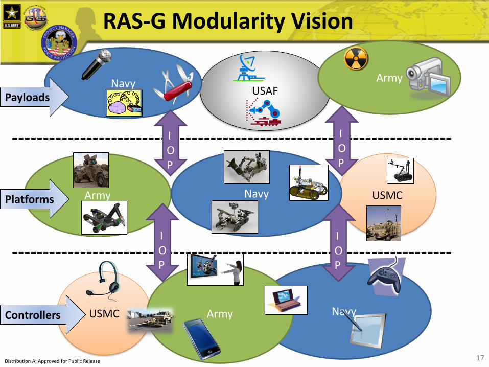
RAS-G IOPs Basic Overview
• Robotics & Autonomous Systems, Ground (RAS-G) Interoperability Profiles (IOPs)
• Defines software messaging & hardware interfaces between major subsystems of unmanned ground systems
16IOP V3.0 Release February 2018Distribution A: Approved for Public Release
USAF
USMC
USMC
Navy
Navy
17
Army
Army Navy
Army
IOP
IOP
IOP
Payloads
Platforms
Controllers
RAS-G Modularity Vision
IOP
Distribution A: Approved for Public Release 17

Existing Universal Controller Requirements & Architecture
18CRS(I)
SMET
Light Reconnaissance Robot (CRS(LR))
RQ-11 Raven(MRR)
RQ-20 Puma(LRR)
Short Range Recon (SRR)
PD-100 / Soldier Borne Sensor (SBS)
Lethal Maneuver Aerial Munition System (LMAMS)
MTRS Inc II
All graphics are notional to convey the general size and type of system
CRS(H)
IOP/JAUS
MTRS MK II
CRS(I) Universal Controller CDD Language: 6.2.2 (U) KPP 6 - Unmanned System Control. The CRS (I) OCU must have the ability to achieve and maintain active and/or passive control of any current Army and Marine Corps PoR battalion and below level Unmanned (Air or Ground) System (UxS) and/or their respective payloads in less than three (T), one (O) minute(s).
CRS(I) (including Universal Controller)
currently in EMD Phase
Acronyms:IOP: Robotics & Autonomous Systems, Ground (RAS-G) Interoperability Profile (IOP)JAUS: Joint Architecture for Unmanned Systems (JAUS)MOCU: Multi-Operator Control Unit
Architecture Extensible to RAS ICD Systems
18
Distribution A: Approved for Public Release

Interoperability
Profiles (IOPs)
Defines hardware & software interfaces between major robotic subsystems
Common
Controller
SPAWAR MOCU 3.0/4.0
Common
Payloads
ERP
CBRN
ROBOTICS COMMONALITY
CRS-ISMET MTRS Inc II
Graphics are notional to convey
the general size and type of system
Acronyms:IOP: Robotics & Autonomous Systems, Ground (RAS-G) Interoperability Profile (IOP)
JAUS: Joint Architecture for Unmanned Systems (JAUS)
MOCU:Multi-Operator Control Unit
CRS(H)
Talon 5a
CRS(I) Universal Controller
CDD Language: 6.2.2 (U) KPP 6 -
Unmanned System Control.
The CRS (I) OCU must have the
ability to achieve and maintain
active and/or passive control of
any current Army and Marine
Corps PoR battalion and below
level Unmanned (Air or Ground)
System (UxS) and/or their
respective payloads in less than
three (T), one (O) minute(s).
Future Robots
Value of Commonality
19Distribution A: Approved for Public Release

• Data rate: > 2 Mbps
– Driven by streaming video requirements• Encoding, Resolution, Color Depth, Frame Rate, Multiple Simultaneous Streams
• Ground-to-Ground LOS/NLOS Distance/Range of < 1km
– Can’t rely on commercial cellular data towers
• Latency < 250 ms
• Resistant to Jamming
• Spectrum Agile
• Channel Selectable
• Low SWaP
– Low power consumption for extended battery operation
– Weight and size
• Compliant with latest version of RAS-G IOP
• Cybersecurity Hardened
• Low Detectability23-Apr-18 20
20
Unique Wireless Comms Requirements
Distribution A: Approved for Public Release
Data Rate
Latency performance
Distance/Range in crowded environment

• Robotic arms & manipulators (grippers, hands, etc) can be
difficult to articulate requirements for
23-Apr-18 2121
Dexterous Manipulators / Specifying Manipulator Performance
Distribution A: Approved for Public Release
OptimalToo
ConstrainingToo
Loose
What does a good performance spec look like?
Images from Google search for “Public Domain _____”

• How do you specify requirements for a system that will
encounter new situations that may result in unexpected or
unplanned for behavior?
• How do you test a system that will encounter new
situations that may result in unexpected or unplanned for
behavior?
• How do you specify requirements for a system that learns?
• How do you test & characterize a system that learns?
23-Apr-18 2222
Managing a System w/ Uncertain Behavior
Distribution A: Approved for Public Release
Education Systems
Report CardsDriver’s License

• Remote system operation– Nuclear contaminated facilities
– Ship inspection, maintenance & repair
– Bridge inspection
• Hard to reach access or delicate operations– Performing of (maintenance) tasks in close quarters (e.g., on ship))
– Changing scale (i.e. miniaturizing surgical hands a la Da Vinci)
• Automated operation– Repetitive tasks – material integrity inspection
– Painting, surface removal, etc.
– Road repair?
• Sensors & intelligence– Machine vision: subtle pattern recognition for quality inspection
– Predictive analytics for CBM+
• Sustainment Mission (Combat Support)– Construction equipment – forklifts, dozers, graders, airfield repair, etc.
– Material handling equipment
– Material resupply 2323
Potential Ground Robotics Applications for Maintenance & Sustainment
Distribution A: Approved for Public Release
(Quick Brainstorm)

Discussion
24Distribution A: Approved for Public Release

23-Apr-18 2525
Requirements & System Definition Cascade
Operational Baseline
Functional Baseline
Product Baseline
CRS(H) CPD
Explosive Hazard Defeat ICD
CRS(H) Performance SpecSystem Level Performance Spec
Allocated Performance Specs
Native Manipulator Arm
PTZ Cameras
Robotic Platform
Controlled by TRADOC
Controlled by PM
TDP or Product Build Specifications
Owned by OEM
TDP or Product Build Specifications
Owned by Third Party Manufacturer
UC Hardware Shell
TDP or Product Build Specifications
Owned by Gov’t
Cameras
Radio Relay
Universal Controller
(UC)
EOD Robotic Payloads (ERP)
(Not defined by CRS(H) PoR)
Radios
Etc.
IOP Interfaces
MOCU 4
ERP Disruptor
(Example of what final product baseline could look like)
Chassis
Wheels/Tracks
10 DOF Arm
Gripper
Etc.
Autonomy Software
Etc.
Informed by mission, threat, etc.
Informed by operational requirements, current state of technology, cost/availability of systems
Informed by performance spec requirements & allocations, designs, manufacturability, cost, IP

As the Army articulates RAS integration across multiple Warfighting Functions, this vision must
also show realistic objectives in the near-term, feasible objectives in the mid-term, and
visionary objectives for the far-term. Beginning with near-term objectives, each successive
phase links its objectives to and builds from the achievements of the previous phase.
Near-Term Vision- Adapt
Mid-Term Vision (F2025)- Evolve
Far-Term Vision- Innovate
Near-Term Objectives: Leader-Follower Convoy
Technology Employment
Lighten the Soldier load
Enhance stand-off from
threats and improve
situational awareness
Mid-Term Objectives: Technologies improve the autonomy of unmanned systems
Technologies will enable unmanned cargo delivery
Robots act as “teammates” rather than tools
Micro autonomous air and ground systems will also enhance Platoon,
Squad, and Soldier situational awareness
Far-Term Objectives:Technologies will enable manned and
unmanned teaming in both air and
ground maneuver though investments
in scalable sensors, scalable teaming,
Soldier-robot communication, and
shared understanding through
advancements in machine learning.
Source for All Listed Objectives: TRADOC Pam 525-3-1, Army Operating Concept, Appendix C-2.
26
Framing the Army’s Robotics and Autonomous Systems (RAS) Strategy
Distribution A: Approved for Public Release

23-Apr-18 2727
PM FP Cybersecurity Considerations
Minimal Cyber Capability
Low Cyber Capability
Moderate Cyber Capability
High Cyber Capability
Advanced Cyber Capability
Robotic Autonomy Applique Systems
Tactical Bridging
Assault Bridging JAB
Desired system cybersecurity implementation maturity
CE/MHE Blades
CE/MHE Lifts
Diggers, Mowers & Cutters
Petroleum Storage & Distribution Systems
Water Systems and Quality Surveillance Systems
NSE Robots
Diving, Boats & Motors
Special Tools
SKOT Engineer
SKOT Ordnance
OPATS/NGATS
TEMOD
CRS(I) & CRS(H)
MTRS Inc II
Characterize cyber risk in DoD Risk Management Framework (RMF) in terms of Confidentiality, Availability & Integrity of data & impacts if system were to be compromised
System Level Vulnerability Analysis
Supply Chain Vulnerability Analysis
Subsystem Level Vulnerability Analysis
Component Level Vulnerability Analysis
Specify Cybersecurity Reqts in RFP
Program Protection Plan (PPP)
Cyber Incident Response Plan
Plan periodic cybersecurity system upgrades in sustainment
Software Stress Testing Red Team / Blue Team Events
Supply Chain Integrity Audits
Basic Wireless Data Encryption
High Wireless Data Encryption
Advanced Wireless Data Encryption
PM FP needs industry’s help in defining this
SAASM/M-Code GPS/PNT
Limited Lifetime Encryption Keys
High Frequency Encryption Key Updates
Authentication Systems
Strong Passwords
SW Message Whitelisting
Digital Certificates
Subsystem Isolation & Access Control
Multi-Layer/Multi-Factor
Spectrum Agile RadiosRF Signal Detection Prevention SW Error Checking Algorithms Message Redundancy & Prioritization Dynamics
Protect Operation/Maintenance ManualsSelf-Monitoring Controls
Graceful Degradation Black Box / Data Logging
Control Access to Diagnostics
Penetration Testing
Automated Code Coverage Testing
3rd Party Code Hacking
Disciplined SE & req’ts definition
Arch/Data-Flow Analysis
Control System Development Environment
Control Access to Data Dictionary
Limit ability to mod firmwareRole-Based Access Control
Dead-Code Removal
How do we characterize these requirements and
industry’s capability into standard RFP
language?
Bridge Health Monitoring
No Information Processing
Type I: Stand-Alone System – No Media
Type II: Stand-Alone System – With Media
Type III: Stand-Alone Network
Type IV: Closed Restricted Network
NETCOM definitions of Stand-Alone Systems:
Large Unmanned Ground Systems
Robotic Combat Vehicles
Note: Color coded programs above are unofficial PM office anticipated classifications
Connected System (NIPRNET, etc.)
CALSETS-C
APATS/MSD
PQAS
Distribution A: Approved for Public Release

28
VI CTORY
C4ISR/EW Systems
Platforms
Controllers
VI CTORY
Robotic Combat Vehicle Interoperability
ROS-M ROS-M
ROS-M
28
Is this the answer?
IOP
IOP

Robotic Enhancement Program (REP)
• “Buy/lease, try and inform” - evaluate state-of-the-art robotic systemsand/or payloads that are Government-Off-The-Shelf (GOTS), Commercial-Off-The-Shelf (COTS) and Non-Developmental Items (NDI)to inform the requirement and acquisition process
• Status:
- REP Cycle 16.1 – 18.1
• Proposals submitted: 186
• Proposals Selected: 50
- REP Cycle 18.2
• Additional proposals submitted: 43
• CoC occurred on 21 March 2018.
• 5 proposed initiatives approved.
29
REP Cycle 19.1 proposal submission windows closes 1 MAY 2018.
REP Submission Site: http://www.peocscss.army.mil/rep.html
Distribution A: Approved for Public Release

• While the exact composition of the Army’s future RAS
portfolio of systems remains volatile, there are several
intended design philosophies that stakeholders can plan to
– regardless of exact requirements.
23-Apr-18 3030
Army Unmanned Ground Systems Design Philosophy
Distribution A: Approved for Public Release
1. Modular Open Systems Approach thru IOP2. Common Mobility Platforms & Varying Mission Payloads3. Design for Growth & Technology Evolution4. Limit Unnecessary Redundancy5. Materiel Development Preference (GOTS>COTS>NDI>Developmental Item)
6. Utilize Modular “Kits” Where Appropriate7. Provide Intelligent Behavior to Existing Systems8. Take Advantage of Intelligent Systems (i.e., CBM+)9. Warfighter Centric Design

• The fundamental guiding design philosophy for RS JPO’s
future portfolio is the MOSA architecture.
• Amid evolving requirements, changing threats, evolving
technology, and obsolescence risks, modularity will
position the PM for managing these trends at minimal
lifecycle cost.
• MOSA will be achieved through interface control using the
RAS-G IOPs.
23-Apr-18 3131
#1: Modular Open-Systems Approach (MOSA)
Distribution A: Approved for Public Release

• Enabled by the MOSA philosophy, the other basic tenet of the Army’s future robotics portfolio design is to utilize a small number of common mobility platforms, which can accept a variety of mission payloads to perform a variety of different missions for a variety of different user groups.
• The 4 major envisioned classes of common mobility platforms are:• Soldier Transportable
• Vehicle Transportable
• Self-Transportable
• Appliqué.
• To achieve this vision, the PM will continue to work with Combat Developers to lay the foundation for a sustainable Family of Systems (FoS) with common platforms for major robotics classes.
23-Apr-18 3232
#2: Common Mobility Platforms & Varying Mission Payloads
Distribution A: Approved for Public Release

• Again based upon the MOSA priority, the Army’s future
fleet of robotic systems will be designed for growth &
technology improvement.
• Size, Weight and Power (SWAP) margins, as well as
additional payload interfaces, will be designed into
appropriate systems to enable growth.
• As the technological improvement of sensors,
manipulators, computing devices, radios, and other
devices continues to accelerate, the design for evolution
will be central to the Army’s future robotics programs.
23-Apr-18 3333
#3: Design for Growth & Technology Evolution
Distribution A: Approved for Public Release

• Peripherally related to modularity and interface
management, the Army intends to optimize its future
robotics systems by limiting unnecessary redundancy.
• What this means is that the system will be capable of
communicating across its internal boundaries in order to
smartly leverage all information available.
• Achieving this design philosophy entails utilizing well
defined data representations and more importantly,
conducting rigorous systems engineering to optimize
system level performance.
23-Apr-18 3434
#4: Limit Unnecessary Redundancy
Distribution A: Approved for Public Release
For example, a mobility platform may include a GPS receiver on it. When this is the case, it becomes unnecessary for any of the other payloads on the system to include their own GPS receiver (unless the requirements for precision are different). Instead, those payloads would simply pull the GPS information from the platform. Similarly, a sensor collecting valuable information can make that information available to other elements of the system to optimize overall behavior.

• As the Army acquires systems to comprise its future
portfolio, it will consider an order of precedence as to the
materiel acquisition model of choice. This general rule of
thumb provides a model for how the PM will acquire
systems:– The 1st tier of preference is to utilize Government-Off-the-Shelf (GOTS)
systems to meet unmanned requirements.
– The 2nd tier of preference is to utilize a Commercial-Off-the-Shelf (COTS)
approach and procure mature end-items.
– The 3rd tier of preference is to acquire Non-Developmental Items (NDI) – this
means taking mature systems from industry and conducting some minor non-
recurring engineering (NRE) in order to meet all requirements.
– The 4th tier of preference is to acquire Developmental Items (DI) – this means
developing systems from the conceptual level and conducting rigorous
systems engineering to transform general concepts into a sustainable,
affordable product.
23-Apr-18 3535
#5: Materiel Development Preference
Distribution A: Approved for Public Release

• In many cases it will be advantageous to separate certain
system functions into different “kits”.
• If a certain function can be made common across varying
systems, it makes sense for that function to be managed
as a common kit.
• Similarly, when the technology pace or obsolescence rate
for certain subsystems are anticipated to move at a
significantly different pace from other parts of the system,
it makes sense for them to be managed as kits.
23-Apr-18 3636
#6: Utilize Modular “Kits” Where Appropriate
Distribution A: Approved for Public Release
The most obvious planned use for this kitted approach is in appliqué kits for converting existing manned systems into unmanned or assistive-driving systems. For these systems, it makes sense to separate functions into an “A-Kit” that provides common autonomous navigation services or other unmanned technologies, and a “B-Kit” that provides the interface to a specific vehicle. In these cases, the “A-Kit” could be a common autonomous perception/navigation kit for use on many different platforms, while the “B-Kit” would be a unique drive-by-wire kit. It may also be of use on these types of systems to include a “C-Kit” that provides mission-specific payload packages. Methods such as axiomatic design may be of use for determining which functions could optimally be “decoupled” from each other through the use of kitted separation.

• As a means for leveraging previous investment and
infrastructure, the Army adopts a philosophy for giving
preference to systems that can augment existing DoD
inventory to exploit unmanned technology, instead of
solely pursuing ground-up new system developments.
• This will avoid redundancy and introduce unmanned
technology gradually into the DoD fleet.
• The appliqué kit approach described previously provides
an example of this preference.
23-Apr-18 3737
#7: Provide Intelligent Behavior to Existing Systems
Distribution A: Approved for Public Release
Two of PM FP’s current programs (the RCIS and the HMDS) have already adopted this approach, and emerging programs (such as that of the Autonomous Convoy Operations (ACO) emerging requirement) will also adopt this approach.
• The nature of unmanned technology (particularly with built-
in modularity) includes a variety of data and software-
enabled data processing on systems.
• The Army’s design philosophy is that this data and data
processing should be exploited (within reasonable cost,
SWAP & requirements basis) to enable additional valuable
capabilities.
23-Apr-18 3838
#8: Take Advantage of Intelligent Systems
Distribution A: Approved for Public Release
A perfect example of a capability that is enabled through the exploitation of data and data processing on unmanned systems is that of Condition Based Maintenance Plus (CBM+). The same data being used to provide intelligent mobility, sub-system monitoring, etc. can be readily used for improving system diagnostics and enabling prognostics and smarter maintenance planning/responsiveness. It should be noted that while there are DoD sub-communities advocating the ground systems adoption of CBM+ and other DoD sub-communities advocating the ground systems adoption of unmanned systems, the same technology can often be used to provide both capabilities.

• Similar to the Occupant-Centric Protection (OCP) design
philosophy that the DoD manned ground systems
community has been moving toward, PM FP adopts a
Warfighter-Centric philosophy that seeks to:
– 1) provide maximum protection by removing the Warfighter from
direct physical danger, and
– 2) minimize the cognitive workload of the Warfighter in stressful
situations and free up the human talents for more creative and
critical-thinking tasks that demand focused attention
23-Apr-18 3939
#9: Warfighter Centric Design
Distribution A: Approved for Public Release