arc flash protection marking guide for centerline low
TRANSCRIPT

1 Publication 2100-AT002A-EN-P—April 2005
Application Techniques
Arc Flash Protection Marking Guide for CENTERLINE® Low VoltageMotor Control Centers
Introduction Safety is a paramount issue when installing, working on and operating any electrical equipment. This includes the Low Voltage Motor Control Centers (LV MCC). Often a MCC is the service entrance equipment handling high levels of power and more importantly, the MCC's protective devices provide the overload and short circuit protection for high levels of short circuit energy. To address safety issues, standards and design requirements have been developed, e.g., electrical shock, fire, marking requirements, etc.
Over the years, technological advancements have contributed to improvements in MCC equipment by introducing new materials, new component designs, improved construction and greater emphasis on safety. In the area of safety, there has been substantial effort to increase understanding and address arc flash hazards. Testing and research work has advanced this technology, resulting in new safety standards and requirements. The new requirements include marking electrical equipment to notify the operator of arc flash hazards, understanding the required steps necessary to address the hazards and use of the proper personal protection equipment.
This guide provides background information and other guidance for the user of CENTERLINE MCCs in addressing the responsibility to meet the arc flash safety standards and requirements.
Arc Flash Standards and Requirements
The arc flash protection marking requirement was initially established in 2000 by the National Fire Protection Association, Standard for Electrical Safety Requirements for Employee Workplaces (NFPA 70E). NFPA 70E applies to workers who install, maintain or repair electrical systems. NFPA 70E is the foundation for federal Occupation Safety Health Act (OSHA). Thus, these NFPA 70E requirements are a U.S. Federal statute.
In 2002, NFPA 70, The National Electrical Code (NEC) added the Article 110.16, and reinforced the flash protection marking of equipment. The NEC article is stated below:
110.16 Flash Protection
Switchboards, panelboards, industrial control panels, and motor control centers that are in other than dwelling occupancies and are likely to

Publication 2100-AT002A-EN-P—April 2005
2 Arc Flash Protection Marking Guide for CENTERLINE® Low Voltage Motor Control Centers
require examination, adjustment, servicing, or maintenance while energized shall be field marked to warn qualified persons of potential electric arc flash hazards. The marking shall be located so as to be clearly visible to qualified persons before examination, adjustment, servicing, or maintenance of the equipment.
FPN No. 1: NFPA 70E-2000, Electrical Safety Requirements for Employee Workplaces, provides assistance in determining severity of potential exposure, planning safe work practices, and selecting personal protective equipment.
FPN No. 2: ANSI Z535.4-1998, Product Safety Signs and Labels, provides guidelines for the design of safety signs and labels for application to products.
As arc flash technology emerges, new developments result in changes to arc flash criteria. For example, in 2004, the NFPA 70E was reissued in a completely new format with changes reflecting new developments.
NOTE: Both the NEC and NFPA 70E Standards are revised regularly. The latest editions of the NEC and NFPA 70E should be used in establishing potential electric arc flash hazards and arc flash marking. To better assist, the NFPA 70E- 2004 clauses, etc. are referenced by being placed in brackets throughout this document.
Arc Flash Marking Clarification
The flash protection marking per NEC Article 110-16 is a field marking requirement and is to be applied by the user for each specific application. The marking is similar to other NEC marking requirements, e.g., voltage, voltage hazard labels, circuits, etc. However, flash protection markings should be based on application information and calculations from the installation site. The intent of the marking is to identify the presence of a potential flash hazard and to provide assistance in determining necessary protective clothing and personal protective equipment (PPE) that should be worn by qualified electrical persons when servicing electrical equipment. The user must establish field marking requirements based upon:
• The level of the on-site personnel safety training • The level of required clothing and required PPE• Consistency for the level of marking of various equipment, e.g.,
switchboards, panelboards, industrial control panels, motor control centers, etc.,
• The available flash energy on each piece of equipment. This energy is determined from short-circuit current, arc duration based on the type and degree of short circuit protection equipment and the distance of the worker from the prospective arc.

Publication 2100-AT002A-EN-P—April 2005
Arc Flash Protection Marking Guide for CENTERLINE® Low Voltage Motor Control Centers 3
NFPA 70E, provides two methods for determining the flash hazard risk and the associated PPE to be used:
1. Generic Hazard/Risk Guidelines defines the PPE by the service task and exposure based on a conservative fault/energy level assessment [NFPA 70E Table 130.7(C)(9)(a)]. This Hazard/Risk Category classification table is straight forward and the simplest to understand (Guideline Method).
2. Arc Flash Analysis Method is conducting a flash hazard energy analysis to determine the actual “Flash Protection Boundary” and the necessary PPE.
NFPA 70E “Generic Hazard/Risk Guidelines” (Guideline Method)
For the Guideline Method one needs to establish the PPE from a table and mark the MCC accordingly. Referring to Table 130.7(C)(9)(a), the NFPA 70E has established flash-energy criteria based on a conservative value (conservative in regards to low voltage MCCs) of 65kA short circuit available fault current and 0.03 second (2 cycle) as the fault clearing time.
NOTE: It should be noted that the Guideline Method is considered an alternate method to the Flash Hazard Analysis Method. In the 2004 issue of the NFPA 70E, an important clarification was added noting that either a higher or lower available fault current could result in higher available arc flash energies. The effect of the clearing time is a critical issue in the level of “let-through” arc flash energy. The point is there is an inference that the Guideline Method may not be conservative for all applications, i.e., although more complex, the Arc Flash Analysis Method may be the optimum method as it addresses the actual sites potential arc-fault energies.
The following are Guideline Method examples of “Hazard/Risk Levels” [NFPA 70E Table 130.7(C)(9)(a)] for 600V Class MCC work tasks and the protective clothing and PPE [NFPA 70E Table 130.7(C)(10)]. Also included are the “Minimum Arc Thermal Performance Exposure Values” in Joules per square centimeters (J/cm2 ATPV) [NFPA 70E Clause 130.7(C)(5), Table 130.7(C)(11)].
NFPA 70E “Generic Hazard/Risk Guidelines” for MCCs are as follows:
• NFPA 70E Hazard/Risk Level 0 (≤ 5 J/cm2 ATPV)– Reading MCC meters– Circuit breaker or fusible handle operation with the MCC unit door
closed– Working on ≤120V MCC control units
Publication 2100-AT002A-EN-P—April 2005
4 Arc Flash Protection Marking Guide for CENTERLINE® Low Voltage Motor Control Centers
NOTE: A threshold incident-energy level for a second-degree burn is defined as 5 J/cm2.
• NFPA 70E Hazard/Risk Level 1 (16.74 J/cm2 ATPV)– Circuit breaker or fusible handle operation with the MCC unit door
open– Opening MCC hinged doors exposing bare, energized parts
• NFPA 70E Hazard/Risk Level 2* (33.47 J/cm2 ATPV)– Working on energized MCC parts (> 120V), e.g. voltage checking, etc.– Removal of bolted covers exposing bare, energized MCC parts– Application of safety grounds after voltage test to MCC conductors
NOTE: The asterisk (*) denotes special NFPA 70E PPE requirements (double-layer rated switching hood and hearing protection). These requirements are in addition to the other NFPA 70E Category 2 requirements for MCC servicing tasks [NFPA 70E Table 130.7(C)(9)(a)].
• NFPA 70E Hazard/Risk Level 3 (104.6 J/cm2 ATPV)– Inserting or withdrawing MCC units
NOTE: This level is based on 0.33 second (20 cycle) fault clearing time [NFPA 70E Table 130.7(C)(9)(a) Note 4].

Publication 2100-AT002A-EN-P—April 2005
Arc Flash Protection Marking Guide for CENTERLINE® Low Voltage Motor Control Centers 5
In Table 130.7(C)(8) of NFPA 70E, the different types of PPE and the corresponding ANSI and ASTM Standards are referenced. Thus, the MCC should be marked for the required, certified, flame resistant (FR) PPE to be worn by the qualified technician in regards to the Hazard/Risk work task to be carried out. For a condensed guide refer to the following:
NFPA 70E Protective Clothing/Equipment [NFPA 70E, Table 130.7 (C)(10)]
• NFPA 70E Hazard/Risk Level 0 for MCC applications– Long sleeve shirt– Long pants– Safety glasses
• NFPA 70E Hazard/Risk Level 1 for MCC applications– Long sleeve FR shirt– Long FR pants– Safety glasses– Hard hat– Leather gloves (as needed)– Leather work shoes (as needed)
• NFPA 70E Hazard/Risk Level 2* for MCC applications– T-shirt (short sleeve)– Long sleeve FR shirt
– FR pants (2nd layer) over long pants – Safety glasses or safety goggles– Double- layer (two FR cloth thickness rating) switching hood as required
by 2*– Hearing protection as required by 2*– Hard hat– Leather gloves – Leather work shoes
NOTE: The asterisk (*) denotes special NFPA 70E PPE requirements (double-layer rated switching hood and hearing protection). These requirements are in addition to the other NFPA 70E Category 2 requirements for MCCs servicing tasks [NFPA 70E Table 130.7(C)(9)(a)].
• NFPA 70E Hazard/Risk Level 3 for MCC applications– T-shirt (short sleeve)– Long sleeve FR shirt– Long pants, plus FR pants (2 Layers)
– FR coverall (3rd Layer) – Safety glasses or safety goggles– Double layer switching hood– Hearing protection– Hard hat with FR liner– Leather gloves– Leather work shoes

Publication 2100-AT002A-EN-P—April 2005
6 Arc Flash Protection Marking Guide for CENTERLINE® Low Voltage Motor Control Centers
Flash Hazard Analysis Method
As previously discussed, the Guideline Method should be considered an alternate method as it is based on a conservative criteria. Although, this may not always be the case in the actual application. The fault current and clearing time are given by NFPA 70E as an example and the actual application may be less, resulting in lower flash hazard energy. Or, in some cases, this could even be higher than the NFPA 70E generic values due to the application's fault current and/or the fault clearing time (the combination of higher or lower fault current with the arcing time). For example, if the fault current is lower, resulting in a longer clearing time for the applications protection device, the flash energy could be substantially greater. This case is especially important in the noncurrent-limiting range or over-current (overload) range of short-circuit protection devices. It may be best not to use the alternate, generic method but to conduct an actual “Flash Hazard Analysis” using the site's actual input criteria. From this analysis the user can determine the site's actual flash hazard determining:
• Actual site flash hazard energy (incident energy)• Actual protective device's projected clearing times• Actual site flash hazard risk• Safety instructions based on both the actual available flash hazard and
the MCC design features• Assign PPE according to the Flash Hazard Energy and Risk• Corresponding required NEC markings.
There can be benefits for the user in applying this approach, instead of using the generic guideline approach because the PPE equipment can be specifically selected to fit the MCC application, “workman friendly” PPE may be applied and a common flash hazard instruction, consistent with other types of equipment may be used. New tools are now available for carrying out the Flash Hazard Analysis. One such tool is IEEE Standard 1584 [IEEE Standard 1584- 2002 “IEEE Guide for Performing Arc Flash Hazard Calculations”].
IEEE Standard 1584 IEEE Standard 1584 on arc flash hazards calculations provides an excellent source for conducting the flash analysis and includes an analysis spreadsheet (including a CD for completing the calculations). This spreadsheet uses Microsoft Excel®. This is a useful tool as each of the sites’ applications can be defined, labeled and assigned the appropriate PPE marking. Simply follow the directions as defined in the IEEE Standard and input the requirements into the spreadsheet from the actual site and the necessary calculations will be carried out by the software. It is recommended to review this IEEE standard as it includes actual field incidents of arcing faults, research testing data, arc-time data and fuse and circuit breaker time-current characteristics (important for developing the arcing time calculations). This is an excellent tool for carrying out the NFPA 70E requirements for conducting the Flash Hazard Analysis and a base for the NEC's requirement for Flash-Protection Marking.

Publication 2100-AT002A-EN-P—April 2005
Arc Flash Protection Marking Guide for CENTERLINE® Low Voltage Motor Control Centers 7
Also included in the IEEE Standard 1584, is good reference material on this new developing area of “Arc Flash Technology.”
Helping Reduce Arc-Flash The CENTERLINE Low Voltage Motor Control Center complies with
• NFPA 70 National Electrical Code (NEC)• Underwriters Laboratories Safety Standards for MCCs - UL845• Canadian Standards Association (CSA) C22.-2, No. 14; standard for
Industrial Control Equipment
The CENTERLINE Low Voltage Motor Control Center incorporates many safety design features
• Insulation and isolation guards and barriers• Current limiting designs• Shutters• Unit lock-out• Optional features and custom designs.
Depending on the MCCs sites’ available flash energy and risk evaluation [NFPA 70E Annex C & D], Electrical Safety Program [NFPA 70E Article 110 and specifically Clause 110.7], safety training [NFPA 70E 110.6] and the features that were incorporated into the specific MCC (standard or custom designs), the user may be able to take these factors into consideration and possibly reduce the NFPA 70E Hazard/Risk Levels. However, the most important step for the safest work environment is to remove the hazard. In the case of MCCs, remove the hazard by shutting off the power to the equipment and locking out and testing that all feed power has been isolated, voltage shall be removed and the absence of voltage shall be verified [NFPA 70E Article 120 and specifically Clause 120.2 (B) (6)].
Refer to the following examples and comments of the CENTERLINE design elements that may be evaluated and considered in the flash hazard energy analysis and the risk evaluation, Flash Hazard Analysis and Procedures [NFPA 70E Clause 110.8(B)(1)(b), Clause 110.7(F), Clause 130.3 and Clause 130.7(C)(9)(a)].
IMPORTANT Each application and site requirements can be different and unique and the examples given are for guidance purpose only. Thus, the user must decide on appropriate safety requirements.
Publication 2100-AT002A-EN-P—April 2005
8 Arc Flash Protection Marking Guide for CENTERLINE® Low Voltage Motor Control Centers
Reduce fault current (bolted fault less than the NFPA 70E benchmark of 50kA or any combination not exceeding 300kA cycles, i.e. 5000 ampere seconds).
Reduction in arc energy can affect the Flash Protection Boundary [NFPA 70E 130.3(A)].
Current limiting devices or reduced clearing time, i.e. Reduction in the Flash Protection Boundary (clearing times less than 6 cycles (0.1s) and low let-through energy)
Series coordination of the main short-circuit protection device may be advisable as it provides not only higher bus capabilities but may result in further reduction of the flash energy.
Consistency of DesignIf different MCC designs are utilized throughout the user's site, the safest operation practice covering all construction should be considered, i.e., standardize safety procedures and field marking.
Barriers and GuardsProperly isolating the work areas below 120V allows a Hazard/Risk Category reduction from Level 2* to 0 [NFPA 70E Clause 130.6(F), Clause 130.7(D)(1)(h), specifically Table 130.(C)(9)(a)].
Automatic Shutters Provide Isolation and InsulationProvides personal protection by isolating and insulating the live bus should a MCC unit be removed or moved to the service position, i.e., a Hazard/Risk Category reduction from Level 2* to 0 [NFPA 70E Clause 130.7(D)(1)(h), specifically Table 130.7(C)(9)(a)]. In addition, the shutters provide isolation which helps restrict an internal arc from spreading to the vertical bus [NFPA 70E Clause 130.7(D)(1)(h)]. See Figure 4.
CENTERLINE MCC Unit Interlock Prohibits the Insertion or Withdrawal of a Unit with the Disconnecting Means in the “ON” or Closed Position
A Hazard/Risk Category reduction from Level 3 to 1 may be possible in combination with defined test procedures, locking-out the unit for the insertion or withdrawing operation and using automatic shutters. The NFPA 70E's “Safety-Related Work Practices” and “Establishing an Electrically Safe Work Condition” must be addressed specifically for the operation [NFPA 70E Article 110 and Article 120 and specifically Clause 110.7]. See Figure 2.
Withdrawable CENTERLINE MCC Units Allow Servicing Units while Isolated from Power Bus
Utilizing the CENTERLINE MCC unit's service position in combination with the use of automatic shutters and lock-out procedures, a Hazard/Risk Category reduction from Level 2* to 0 may be achieved [NFPA 70E Clause 130.7(D)(1)(h) and Table 130.7(C)(9)(a)]. See Figure 2, Figure 3 and Figure 4.

Publication 2100-AT002A-EN-P—April 2005
Arc Flash Protection Marking Guide for CENTERLINE® Low Voltage Motor Control Centers 9
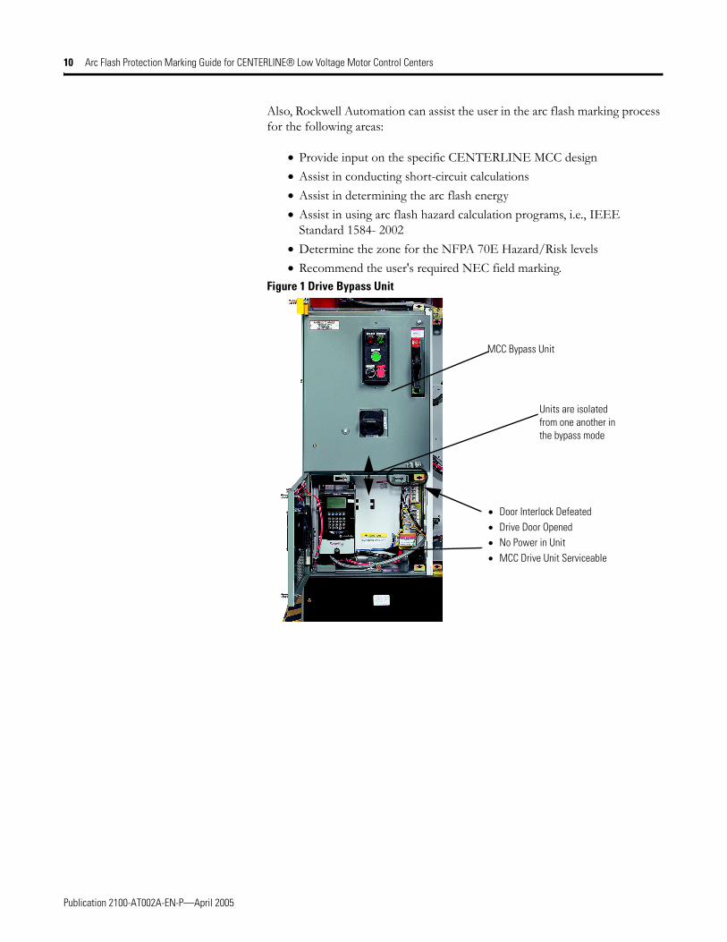
Low Energy Drive CompartmentsUtilizing a two compartment drive unit with a high and a low energy compartments, allows the drive unit to be isolated for servicing. This type of designed isolation can reduce the Hazard/Risk Category by one level. In the case of the bypass drive design with its lockout/tagout design, the Hazard/Risk Category can be reduced to Level 0 [NFPA 70E, Article 120 and specifically Clause 120.2(E)(3)]. See Figure 1. For more information refer to publication 2100-SR009x-EN-P, Manual Isolated Drive Bypass Unit in CENTERLINE® Motor Control Centers.
MCC Unit OperationThe operation (opening or closing) of the MCC unit's disconnecting means with the MCC's enclosure door closed is a Hazard/Risk Category Level 0 and with the enclosure door open is increased to a Hazard/Risk Category Level 1 [NFPA 70E Table 130.7(C)(9)(a)]. In applications, especially heavy industrial, where the level of available electrical energy is high (high fault current and long clearing times) and a resulting high arc flash potential, a Hazard/Risk Category Level 1 should be considered in the switching of any electrical equipment. Also, it is important to remember the “left-hand rule,” which is required by most safety procedures. The rule requires the operator to stand to the right of the equipment and not be directly in front of the equipment, forcing the operator to operate the device with the left hand.
Special MCC Internal Arc-Fault Latches - OptionalThese latches are designed to withstand and provide MCC unit containment from the pressure and arc flash hazard. Defined high available fault current (e.g., 65kA at 600V) tests have been conducted to demonstrate the effectiveness of these special latches. By deliberately initiating an arcing fault inside MCC compartments, these internal arc-fault latches have withstood the force from the arcing-fault gas pressure and contained the arcing fault. Thus, should a component failure occur inside the MCC compartment (when used on bus systems that meet specific ratings and specific fuses or circuit breakers) arc fault latches can provide an extra level of protection and safety.
Rockwell Automation Assistance
Rockwell Automation can assist the user with questions about compliance and responsibilities for meeting NEC/NFPA 70E requirements.
Publication 2100-AT002A-EN-P—April 2005
10 Arc Flash Protection Marking Guide for CENTERLINE® Low Voltage Motor Control Centers
Also, Rockwell Automation can assist the user in the arc flash marking process for the following areas:
• Provide input on the specific CENTERLINE MCC design • Assist in conducting short-circuit calculations• Assist in determining the arc flash energy• Assist in using arc flash hazard calculation programs, i.e., IEEE
Standard 1584- 2002• Determine the zone for the NFPA 70E Hazard/Risk levels • Recommend the user's required NEC field marking.
Figure 1 Drive Bypass Unit
MCC Bypass Unit
Units are isolated from one another in the bypass mode
• Door Interlock Defeated • Drive Door Opened• No Power in Unit • MCC Drive Unit Serviceable

Publication 2100-AT002A-EN-P—April 2005
Arc Flash Protection Marking Guide for CENTERLINE® Low Voltage Motor Control Centers 11
Figure 2 Unit is Service Position
Figure 3 Unit Interlock Disconnect Latch Mechanism
Can be Tagged-out or Padlocked
Withdrawn and interlocked in service position (disconnected)
Unit Interlock Disconnect Latch Mechanism

Publication 2100-AT002A-EN-P - April 2005 12 © 2005 Rockwell Automation, Inc. All rights reserved. Printed in the U.S.A.
Figure 4 Shutters Protect User from Vertical Bus
Shutters block openings to vertical bus
(Provides isolation and insulation)