approved components list mechanical components · as series maintenance units, namur valve, ......
TRANSCRIPT

Version date: Jan. 1, 2017
Version: 1.9 Page 1 of 69
Approved Components List Mechanical Components
For Manufacturing of Engines, Transmissions, Chassis,
Foundry of the Volkswagen Group “Technology-Specific Part”

______________________________________________________________________________________________________
Aventics GmbH - Approved_Components_List_Mechanical_Components.docx
Version 1.9 / 01.01.2017
Page 2 of 69
Modification history
Vers. Date: Type of change Page
0.0 01.12.2006 First edition All
0.1 09.06.2008 Contact persons
Explanation of file names
Description of PDF document
Components
0.2 30.06.2008 Expansion of the foundry at the Hanover location 1
1.1 01.08.2008 Expansion of the Hanover location 1
1.2 03.08.2009 Functional specifications for mechanical components revised (version 1.2) Release list renamed: “Assembly production – chassis, transmission, engine“ Expansion of the Wolfsburg location
1 1 1 1
1.3 01.01.2010 Version 1
1.4 01.07.2012 Version
Contact persons,
AS series maintenance units,
Namur valve,
time switching valve and filling units
1
6
55
30
31
1.5 01.01.2013 Version 1
1.6 01.01.2014 Version
Trade name
Cylinder series PRA DM 125 version
Cylinder series ITS DM 160 – 200 change of series
Maintenance units with E11
1
All
8
11
From 55
1.7 01.01.2015 Version
Trade name
Aventics contact
Maintenance units without E11
Maintenance units without pressure switch, without distributor
1
All
6
49
56
1.7 30.04.2015 Distributors included again at the end of the maintenance units section
56
1.8 01.01.2016 Valve system AV03 and AV05 holder
PU tube holder
QR1 series fittings, holder
42
51
53
1.9 01.01.2017 Filter, -regulator, change to manual condensate drain 57,61, ff.

Aventics GmbH - Approved_Components_List_Mechanical_Components.docx
Version 1.9 / 01.01.2017
Page 3 of 69
Content
Modification history 2
Content 3
1. Aventics contacts 6
2. Remarks 8
3. Overview 8
4. Release list for components 8
4.1 Energy conversion 8 4.1.2 Pneumatic cylinders 8 4.1.2.1 Double-acting cylinders Ø32 mm to Ø200 mm DIN ISO 15552 8
4.1.2.1.1 PRA series (profile cylinders) – Ø 32 mm to Ø 125 mm 8
4.1.2.1.2 ITS series (tie rod cylinders) – Ø 160 mm to Ø 200 mm 11
4.1.2.1.3 Cylinder accessories for cylinders acc. to DIN ISO 15552 12
4.1.2.3 Double-acting small pneumatic cylinders Ø 10 mm to Ø 25 mm; ISO 6432 17
4.2.1.3.1 MNI series (mini cylinder) – Ø 10 mm to Ø 25 mm 17
4.1.2.3.3 Add-on parts for small pneumatic cylinders acc. to DIN ISO 8139 / 8140 18
4.1.2.4 Rodless cylinders Ø 32 mm to Ø 80 mm: 19
4.1.2.4.1 RTC series – Basic Version 19
4.1.2.4.2 RTC series – Heavy Duty version 21
4.1.2.4.3 RTC series – Compact Guide version 22
4.1.2.4.4 RTC series – Accessories 22
4.1.2.5 Swivel motors (rotary actuators) 23
4.1.2.5.1 TRR series 23
4.1.2.5.2 RAN series 24
4.1.2.6 Compact cylinders ISO 21287 piston rod, Ø 20 mm to Ø 80 mm 25
4.1.2.6.1 CCI series piston rod with internal thread, Ø 20 mm to Ø 80 mm 25
4.1.2.6.2 CCI series piston rod non-rotating, Ø 20 mm to Ø 80 mm 26
4.1.2.6.3 CCI series add-on parts 27
4.2 Energy control and regulation 28 4.2.1 Directional valves and accessories 28 4.2.1.1 Directional valves, electromagnetically operated 28 4.2.1.2 3/2 directional valves, electromagnetically operated 28
4.2.1.2.1 5/2 - electromagnetically operated with Namur porting configuration 29
4.2.1.2.2 Pneumatically operated and time switching valve 30
4.2.1.2.3 Cleaning pressure modules 30

Aventics GmbH - Approved_Components_List_Mechanical_Components.docx
Version 1.9 / 01.01.2017
Page 4 of 69
4.2.1.2.4 Mechanically (manually) operated 31
4.2.1.3 5/2 and 5/3 directional valves acc. to ISO 5599-1 32
4.2.1.3.1 Size 1, electrically operated 32
4.2.1.3.2 Size 1, pneumatically operated 33
4.2.1.3.3 Size 3, electrically operated 34
Size 3 pneumatically operated 35
4.2.1.4 Accessories for directional valves acc. to ISO 5599-1 35
4.2.1.4.1 Single subbases, ports on side, VDMA 24345 A…G 35
4.2.1.4.2 Single subbases, ports on bottom, VDMA 24345 A…G 36
4.2.1.4.3 Sandwich plates, working connections on bottom, VDMA 24345 C…G 36
4.2.1.4.4 End plate kits VDMA 24345 D…G 37
4.2.1.4.5 Angle subbases VDMA 24345 E 37
4.2.1.4.6 Blanking plates 38
4.2.1.4.7 Throttle plates 38
4.2.1.5 5/2 and 5/3 directional valves acc. to ISO 15407-1, VDMA 24563 39
4.2.1.5.1 Directional valves, electrically operated with M12 connection 39
4.2.1.5.2 Contact bridges with M12 connection 40
4.2.1.5.3 Pneumatically operated directional valves 41
4.2.1.5.4 Subbases acc. to ISO 15407-1 42
4.2.2 Valve systems – VS 43
4.2.2.1 VS series AV03 300 l/min 43
4.2.2.1.1 Valves and plates 43
4.2.2.2 VS series AV05 700 l/min 44
4.2.2.2.1 Valves and plates 44
4.2.2.3 Bus coupler for AV03 and AV05 45
4.2.2.3.1 ProfiNet IO, Profibus DP 45
4.2.2.3.2 Input modules 45
4.2.2.4 VS – Accessories 46
4.2.2.5 Configurator 47
4.2.3 Blocking valves 48
4.2.3.1 Non-return valves 48
4.2.3.2 Pilot-operated non-return valves and manual exhaust 48
4.2.3.3 Double check valves 50
4.2.3.4 Quick exhaust valves 50
4.2.3.5 Twin pressure valves 50
4.2.4 Pressure valves 51 4.2.5 Flow control valves 51 4.2.5.2 Throttle valve 51
4.2.5.3 Check-choke valves 51
4.2.5.3.1 Manually adjustable with internal thread 51
4.2.5.3.2 Exhaust and inlet-side throttling 52
4.3 Energy transmission 53 4.3.1 Tubing and tubing connections 53 4.3.1.3 Push-in fitting for tubing Ø4, Ø6, Ø8, Ø10, Ø12, Ø14 55

Aventics GmbH - Approved_Components_List_Mechanical_Components.docx
Version 1.9 / 01.01.2017
Page 5 of 69
4.3.1.3.1 QR1-S series, standard 55
4.3.1.3.2 QR2-S series, standard 55
4.3.2 Filters and filter regulators, fully automatic 56 4.3.4 Pressure regulators 57 4.3.4.1 Manually adjustable 57
4.3.4.1.1 Without E11 locking with lockable handwheel (without lock) 57
4.3.4.1.2 Manually adjustable, with E11 locking 57
4.3.4.1.3 Precision pressure regulator, manually adjustable 58
4.3.5 Maintenance units from stand-alone devices 58 4.3.6 Silencer and throttle with silencer 59 4.4. Additional equipment 60 4.4.1 PG1-SNL-ADJ series and SAS-ADJ series pressure gauges 60 4.4.2 PM1 series mechanical pressure switch, setting range 0.5 bar to 16 bar 61
4.5. Other energy control and regulation 62
5.1. Maintenance units 62 5.1.1 Ultrafilter unit 62 5.1.2 Complete maintenance units AS2, AS3, and AS5 63 5.1.2.1 AS2 series without sealing air 63
5.1.2.2 AS2 series with sealing air, electrical, without timer 64
5.1.2.3 AS2 series with sealing air, electrical, with pneumatic timer 65
5.1.2.4 AS3 series without sealing air 66
5.1.2.7 AS5 series without sealing air 69
5.1.2.8 AS5 series with sealing air, electrical, without timer 70
5.1.2.9 AS5 series with sealing air, electrical, with pneumatic timer 71

Aventics GmbH - Approved_Components_List_Mechanical_Components.docx
Version 1.9 / 01.01.2017
Page 6 of 69
1. Aventics contacts
VOLKSWAGEN AG: Aventics GmbH Mr. Tim Melches
International Key Account Manager Karlsruher Strasse 2C 30519 Hanover, Germany Tel. +49 (511) 2136-595 Cell +49 (0) 151 12624193 E-mail [email protected]
AUDI AG:
Aventics GmbH Mr. Manuel Görbert Pneumatics sales region south Heisenbergbogen 2 83609 Aschheim, Germany Tel. +49 (89) 2154780-15 Fax +49 (89) 2154780-50 Cell +49 (0) 172 3663946 E-mail [email protected]
SKODA AUTO:
Aventics GmbH
Mr. Tomas Boril
CZ pneumatics sales for Skoda
Prazská 675/10
CZ-642 00 Brno
Tel. +420 (530) 515 555
Fax +420 (530) 515 551
Cell +420 (602) 784 067
E-mail [email protected]

Aventics GmbH - Approved_Components_List_Mechanical_Components.docx
Version 1.9 / 01.01.2017
Page 7 of 69
Continuation of Aventics GmbH contacts for
VOLKSWAGEN AG:
Plants: Wolfsburg, Braunschweig, Salzgitter, Hanover
Aventics GmbH
Mr. Detlef Reyher
Pneumatics Sales Region North-East
Walsroder Straße 93
30853 Hanover-Langenhagen, Germany
Tel. +49 (391) 53426975
Fax +49 (391) 53426977
Cell +49 (0) 172 5102663
E-mail [email protected]
VOLKSWAGEN AG:
Plant: Kassel Aventics GmbH
Mr. Ernst-Georg Tesch
Pneumatics Sales Region North-East
Walsroder Straße 93
30853 Hanover-Langenhagen, Germany
Tel. +49 (555) 39945501
Fax +49 (511) 726657-91
Cell +49 (0) 173 2363089
E-mail [email protected]
Aventics GmbH - Approved_Components_List_Mechanical_Components.docx
Version 1.9 / 01.01.2017
Page 8 of 69
2. Remarks The following tables list all components that may be used for planning of pneumatic systems for the production units of the Volkswagen Group listed on page 1.
Written exemption must be obtained for components that are not listed or included in this table.
This release list was prepared in cooperation with the Volkswagen Group.
Technical information for the pneumatic components can be viewed and downloaded at the link below.
Technical information
Drawings similar. Subject to change.
3. Overview
4. Release list for components
4.1 Energy conversion
4.1.2 Pneumatic cylinders
4.1.2.1 Double-acting cylinders Ø32 mm to Ø200 mm DIN ISO 15552
4.1.2.1.1 PRA series (profile cylinders) – Ø 32 mm to Ø 125 mm
Cylinders acc. to DIN ISO 15552,
Released components are listed below.
For dimensions and additional information see our online catalog: PRA series
Designation (type) Ø x stroke in mm Order number Comment
PRA series profile cylinder Ø 32 * 25 0822120001
PRA series profile cylinder Ø 32 * 50 0822120002
PRA series profile cylinder Ø 32 * 80 0822120003
PRA series profile cylinder Ø 32 * 100 0822120004
PRA series profile cylinder Ø 32 * 125 0822120005
PRA series profile cylinder Ø 32 * 160 0822120006
PRA series profile cylinder Ø 32 * 200 0822120007
PRA series profile cylinder Ø 32 * 250 0822120008
PRA series profile cylinder Ø 32 * 320 0822120009
Aventics GmbH - Approved_Components_List_Mechanical_Components.docx
Version 1.9 / 01.01.2017
Page 9 of 69
PRA series profile cylinder Ø 32 * 400 0822120010
PRA series profile cylinder Ø 32 * 500 0822120011
PRA series profile cylinder Ø 50 * 25 0822122001
PRA series profile cylinder Ø 50 * 50 0822122002
PRA series profile cylinder Ø 50 * 80 0822122003
PRA series profile cylinder Ø 50 * 100 0822122004
PRA series profile cylinder Ø 50 * 125 0822122005
PRA series profile cylinder Ø 50 * 160 0822122006
PRA series profile cylinder Ø 50 * 200 0822122007
PRA series profile cylinder Ø 50 * 250 0822122008
PRA series profile cylinder Ø 50 * 320 0822122009
PRA series profile cylinder Ø 50 * 400 0822122010
PRA series profile cylinder Ø 50 * 500 0822122011
PRA series profile cylinder Ø 63 * 25 0822123001
PRA series profile cylinder Ø 63 * 50 0822123002
PRA series profile cylinder Ø 63 * 80 0822123003
PRA series profile cylinder Ø 63 * 100 0822123004
PRA series profile cylinder Ø 63 * 125 0822123005
PRA series profile cylinder Ø 63 * 160 0822123006
PRA series profile cylinder Ø 63 * 200 0822123007
PRA series profile cylinder Ø 63 * 250 0822123008
PRA series profile cylinder Ø 63 * 320 0822123009
PRA series profile cylinder Ø 63 * 400 0822123010
PRA series profile cylinder Ø 63 * 500 0822123011
PRA series profile cylinder Ø 80 * 50 0822124002
PRA series profile cylinder Ø 80 * 80 0822124003
PRA series profile cylinder Ø 80 * 100 0822124004
PRA series profile cylinder Ø 80 * 125 0822124005
PRA series profile cylinder Ø 80 * 160 0822124006
PRA series profile cylinder Ø 80 * 200 0822124007
PRA series profile cylinder Ø 80 * 250 0822124008
PRA series profile cylinder Ø 80 * 320 0822124009
PRA series profile cylinder Ø 80 * 400 0822124010
PRA series profile cylinder Ø 80 * 500 0822124011
PRA series profile cylinder Ø 100 * 50 0822125002
PRA series profile cylinder Ø 100 * 80 0822125003
PRA series profile cylinder Ø 100 * 100 0822125004
PRA series profile cylinder Ø 100 * 125 0822125005
PRA series profile cylinder Ø 100 * 160 0822125006
PRA series profile cylinder Ø 100 * 200 0822125007
PRA series profile cylinder Ø 100 * 250 0822125008
PRA series profile cylinder Ø 100 * 320 0822125009
PRA series profile cylinder Ø 100 * 400 0822125010

Aventics GmbH - Approved_Components_List_Mechanical_Components.docx
Version 1.9 / 01.01.2017
Page 10 of 69
PRA series profile cylinder Ø 100 * 500 R480140491
PRA series profile cylinder Ø 125 * 25 R480140491
PRA series profile cylinder Ø 125 * 50 R480140455
PRA series profile cylinder Ø 125 * 80 R480141347
PRA series profile cylinder Ø 125 * 100 R480079499
PRA series profile cylinder Ø 125 * 125 R480140083
PRA series profile cylinder Ø 125 * 160 R480079809
PRA series profile cylinder Ø 125 * 200 R480140833
PRA series profile cylinder Ø 125 * 250 R480141106
PRA series profile cylinder Ø 125 * 320 R480140759
PRA series profile cylinder Ø 125 * 400 R480141373
PRA series profile cylinder Ø 125 * 500 R480141666

Aventics GmbH - Approved_Components_List_Mechanical_Components.docx
Version 1.9 / 01.01.2017
Page 11 of 69
4.1.2.1.2 ITS series (tie rod cylinders) – Ø 160 mm to Ø 200 mm
Cylinders acc. to DIN ISO 15552
Released components are listed below.
For dimensions and additional information see our online catalog: ITS series
Designation (type) Ø x stroke in mm Order number Comment
ITS series tie rod cylinders Ø 160 * 25 R480627295
ITS series tie rod cylinders Ø 160 * 50 R480627296
ITS series tie rod cylinders Ø 160 * 80 R480627297
ITS series tie rod cylinders Ø 160 * 100 R480627298
ITS series tie rod cylinders Ø 160 * 125 R480627299
ITS series tie rod cylinders Ø 160 * 160 R480627300
ITS series tie rod cylinders Ø 160 * 200 R480627301
ITS series tie rod cylinders Ø 160 * 250 R480627302
ITS series tie rod cylinders Ø 160 * 320 R480627303
ITS series tie rod cylinders Ø 160 * 400 R480627304
ITS series tie rod cylinders Ø 160 * 500 R480627305
ITS series tie rod cylinders Ø 200 * 25 R480627367
ITS series tie rod cylinders Ø 200 * 50 R480627368
ITS series tie rod cylinders Ø 200 * 80 R480627369
ITS series tie rod cylinders Ø 200 * 100 R480627370
ITS series tie rod cylinders Ø 200 * 125 R480627371
ITS series tie rod cylinders Ø 200 – 160 R480627372
ITS series tie rod cylinders Ø 200 * 200 R480627373
ITS series tie rod cylinders Ø 200 * 250 R480627374
ITS series tie rod cylinders Ø 200 * 320 R480627375
ITS series tie rod cylinders Ø 200 * 400 R480627376
ITS series tie rod cylinders Ø 200 * 500 R480627377
Aventics GmbH - Approved_Components_List_Mechanical_Components.docx
Version 1.9 / 01.01.2017
Page 12 of 69
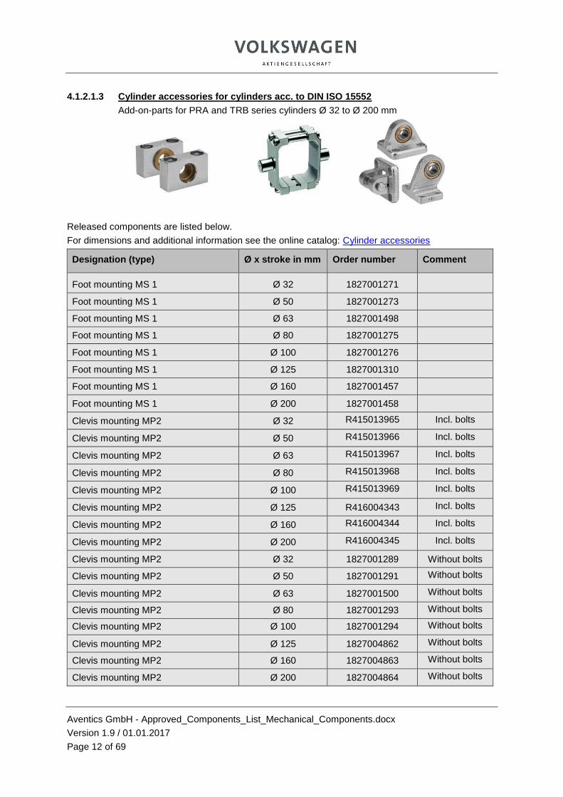
4.1.2.1.3 Cylinder accessories for cylinders acc. to DIN ISO 15552
Add-on-parts for PRA and TRB series cylinders Ø 32 to Ø 200 mm
Released components are listed below.
For dimensions and additional information see the online catalog: Cylinder accessories
Designation (type) Ø x stroke in mm Order number Comment
Foot mounting MS 1 Ø 32 1827001271
Foot mounting MS 1 Ø 50 1827001273
Foot mounting MS 1 Ø 63 1827001498
Foot mounting MS 1 Ø 80 1827001275
Foot mounting MS 1 Ø 100 1827001276
Foot mounting MS 1 Ø 125 1827001310
Foot mounting MS 1 Ø 160 1827001457
Foot mounting MS 1 Ø 200 1827001458
Clevis mounting MP2 Ø 32 R415013965 Incl. bolts
Clevis mounting MP2 Ø 50 R415013966 Incl. bolts
Clevis mounting MP2 Ø 63 R415013967 Incl. bolts
Clevis mounting MP2 Ø 80 R415013968 Incl. bolts
Clevis mounting MP2 Ø 100 R415013969 Incl. bolts
Clevis mounting MP2 Ø 125 R416004343 Incl. bolts
Clevis mounting MP2 Ø 160 R416004344 Incl. bolts
Clevis mounting MP2 Ø 200 R416004345 Incl. bolts
Clevis mounting MP2 Ø 32 1827001289 Without bolts
Clevis mounting MP2 Ø 50 1827001291 Without bolts
Clevis mounting MP2 Ø 63 1827001500 Without bolts
Clevis mounting MP2 Ø 80 1827001293 Without bolts
Clevis mounting MP2 Ø 100 1827001294 Without bolts
Clevis mounting MP2 Ø 125 1827004862 Without bolts
Clevis mounting MP2 Ø 160 1827004863 Without bolts
Clevis mounting MP2 Ø 200 1827004864 Without bolts
Aventics GmbH - Approved_Components_List_Mechanical_Components.docx
Version 1.9 / 01.01.2017
Page 13 of 69
Bearing block AB7 with fixed bearing and foot Ø 32 1825805275
Bearing block AB7 with fixed bearing and foot Ø 50 1825805277
Bearing block AB7 with fixed bearing and foot Ø 63 1825805278
Bearing block AB7 with fixed bearing and foot Ø 80 1825805279
Bearing block AB7 with fixed bearing and foot Ø 100 1825805280
Bearing block AB7 with fixed bearing and foot Ø 125 1825805281
Bearing block AB7 with fixed bearing and foot Ø 160 1825805282
Bearing block AB7 with fixed bearing and foot Ø 200 1825805283
Continuation: Cylinder accessories for PRA and TRB series cylinders Ø 32 to Ø 200 mm
Released components are listed below.
For dimensions and additional information see the online catalog: Cylinder accessories
Designation (type) Ø x stroke in mm Order number Comment
Axle AA4 Ø 32 1823120020
Axle AA4 Ø 50 1823120022
Axle AA4 Ø 63 1823120023
Axle AA4 Ø 80 1823120024
Axle AA4 Ø 100 1823120025
Axle AA4 Ø 125 5236000092
Axle AA4 Ø 160 5237000092
Axle AA4 Ø 200 5237000092
Flange mounting MF1, MF2 Ø 32 1827001277
Flange mounting MF1, MF2 Ø 50 1827001279
Flange mounting MF1, MF2 Ø 63 1827001499
Flange mounting MF1, MF2 Ø 80 1827001281
Flange mounting MF1, MF2 Ø 100 1827001282
Flange mounting MF1, MF2 Ø 125 1827004861
Flange mounting MF1, MF2 Ø 160 1827001460
Flange mounting MF1, MF2 Ø 200 1827001461
Trunnion mounting MT4 for PRA series Ø 32 1827003991
Trunnion mounting MT4 for PRA series Ø 50 1827003993
Trunnion mounting MT4 for PRA series Ø 63 1827003994
Trunnion mounting MT4 for PRA Ø 80 1827003995

Aventics GmbH - Approved_Components_List_Mechanical_Components.docx
Version 1.9 / 01.01.2017
Page 14 of 69
series
Trunnion mounting MT4 for PRA series Ø 100 1827003996
Trunnion mounting MT4 for TRB series Ø 125 1827005948
Trunnion mounting MT4 for TRB series Ø 160 1827005949
Trunnion mounting MT4 for TRB series Ø 200 1827005950
Bearing brackets AT4 for trunnion mounting MT4 Ø 32 1827001603
Bearing brackets AT4 for trunnion mounting MT4 Ø 50 1827001604
Bearing brackets AT4 for trunnion mounting MT4 Ø 63 1827001605
Bearing brackets AT4 for trunnion mounting MT4 Ø 80 1827001605
Continuation: Cylinder accessories for PRA and TRB series cylinders Ø 32 to Ø 200 mm
Released components are listed below.
For dimensions and additional information see the online catalog: Cylinder accessories
Designation (type) Ø x stroke in mm Order number Comment
Bearing brackets AT4 for trunnion mounting MT4
Ø 100 1827001606
Bearing brackets AT4 for trunnion mounting MT4
Ø 125 1827001606
Bearing brackets AT4 for trunnion mounting MT4
Ø 160 1827001607
Bearing brackets AT4 for trunnion mounting MT4
Ø 200 1827001607
Axle AA6 non-rotating Ø 32 5230000082
Axle AA6 non-rotating Ø 50 5232000082
Axle AA6 non-rotating Ø 63 5233000082
Axle AA6 non-rotating Ø 80 5234000082
Axle AA6 non-rotating Ø 100 5235000082
Axle AA6 non-rotating Ø 125 5236000082
Axle AA6 non-rotating Ø 160 5237000082
Axle AA6 non-rotating Ø 200 5237000082
Rod clevis AP2 for cylinders Ø 32 1822122024
Rod clevis AP2 for cylinders Ø 50 1822122005
Rod clevis AP2 for cylinders Ø 63 1822122005
Rod clevis AP2 for cylinders Ø 80 1822122004
Rod clevis AP2 for cylinders Ø 100 1822122004
Rod clevis AP2 for cylinders Ø 125 1827001493
Rod clevis AP2 for cylinders Ø 160 1827001471

Aventics GmbH - Approved_Components_List_Mechanical_Components.docx
Version 1.9 / 01.01.2017
Page 15 of 69
Rod clevis AP2 for cylinders Ø 200 1827001471
Bearing block AB7 with fixed bearing and foot
Ø 32 1825805275
Bearing block AB7 with fixed bearing and foot
Ø 50 1825805277
Bearing block AB7 with fixed bearing and foot
Ø 63 1825805278
Bearing block AB7 with fixed bearing and foot
Ø 80 1825805279
Bearing block AB7 with fixed bearing and foot
Ø 100 1825805280
Bearing block AB7 with fixed bearing and foot
Ø 125 1825805281
Bearing block AB7 with fixed bearing and foot
Ø 160 1825805282
Bearing block AB7 with fixed bearing and foot
Ø 200 1825805283
Clevis mounting AB6 incl. pivot pins Ø 32 1827001593
Clevis mounting AB6 incl. pivot pins Ø 50 1827001595
Clevis mounting AB6 incl. pivot pins Ø 63 1827002024
Clevis mounting AB6 incl. pivot pins Ø 80 1827001597
Clevis mounting AB6 incl. pivot pins Ø 100 1827001598
Clevis mounting AB6 incl. pivot pins Ø 125 1827001599
Clevis mounting AB6 incl. pivot pins Ø 160 1827001600
Clevis mounting AB6 incl. pivot pins Ø 200 1827001601
Ball eye rod end AP6 Ø 32 1822124003
Ball eye rod end AP6 Ø 50 1822124005
Continuation: Cylinder accessories for PRA and TRB series cylinders Ø 32 to Ø 200 mm
Released components are listed below.
For dimensions and additional information see the online catalog: Cylinder accessories
Designation (type) Ø x stroke in mm Order number Comment
Ball eye rod end AP6 Ø 63 1822124005
Ball eye rod end AP6 Ø 80 1822124006
Ball eye rod end AP6 Ø 100 1822124006
Ball eye rod end AP6 Ø 125 1822124013
Ball eye rod end AP6 Ø 160 1822124008
Ball eye rod end AP6 Ø 200 1822124008
Bearing block with spherical bearings, angled, acc. to VDMA 24562 part 2
Ø 32 1827001784
Bearing block with spherical bearings, angled, acc. to VDMA 24562 part 2
Ø 50 1827001786
Aventics GmbH - Approved_Components_List_Mechanical_Components.docx
Version 1.9 / 01.01.2017
Page 16 of 69
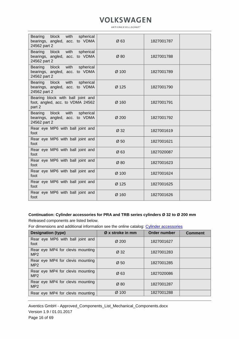
Bearing block with spherical bearings, angled, acc. to VDMA 24562 part 2
Ø 63 1827001787
Bearing block with spherical bearings, angled, acc. to VDMA 24562 part 2
Ø 80 1827001788
Bearing block with spherical bearings, angled, acc. to VDMA 24562 part 2
Ø 100 1827001789
Bearing block with spherical bearings, angled, acc. to VDMA 24562 part 2
Ø 125 1827001790
Bearing block with ball joint and foot, angled, acc. to VDMA 24562 part 2
Ø 160 1827001791
Bearing block with spherical bearings, angled, acc. to VDMA 24562 part 2
Ø 200 1827001792
Rear eye MP6 with ball joint and foot
Ø 32 1827001619
Rear eye MP6 with ball joint and foot
Ø 50 1827001621
Rear eye MP6 with ball joint and foot
Ø 63 1827020087
Rear eye MP6 with ball joint and foot
Ø 80 1827001623
Rear eye MP6 with ball joint and foot
Ø 100 1827001624
Rear eye MP6 with ball joint and foot
Ø 125 1827001625
Rear eye MP6 with ball joint and foot
Ø 160 1827001626
Continuation: Cylinder accessories for PRA and TRB series cylinders Ø 32 to Ø 200 mm
Released components are listed below.
For dimensions and additional information see the online catalog: Cylinder accessories
Designation (type) Ø x stroke in mm Order number Comment
Rear eye MP6 with ball joint and foot
Ø 200 1827001627
Rear eye MP4 for clevis mounting MP2
Ø 32 1827001283
Rear eye MP4 for clevis mounting MP2
Ø 50 1827001285
Rear eye MP4 for clevis mounting MP2
Ø 63 1827020086
Rear eye MP4 for clevis mounting MP2
Ø 80 1827001287
Rear eye MP4 for clevis mounting Ø 100 1827001288

Aventics GmbH - Approved_Components_List_Mechanical_Components.docx
Version 1.9 / 01.01.2017
Page 17 of 69
MP2
Rear eye MP4 for clevis mounting MP2
Ø 125 1827004866
Rear eye MP4 for clevis mounting MP2
Ø 160 1827004867
Rear eye MP4 for clevis mounting MP2
Ø 200 1827004868
Additional accessories, e.g. LU locking unit series, are agreed on request via
special approval.
4.1.2.3 Double-acting small pneumatic cylinders Ø 10 mm to Ø 25 mm;
ISO 6432
4.2.1.3.1 MNI series (mini cylinder) – Ø 10 mm to Ø 25 mm
Cylinders acc. to ISO 6432
Released components are listed below.
For dimensions and additional information see the online catalog: MNI series
Designation (type) Ø x stroke in mm Order number Comment
MNI series Ø 10 * 25 0822330202
MNI series Ø 10 * 50 0822330203
MNI series Ø 16 * 25 0822332202
MNI series Ø 16 * 50 0822332203
MNI series Ø 16 * 100 0822332205
MNI series Ø 25 * 25 0822334202
MNI series Ø 25 * 50 0822334203
MNI series Ø 25 * 100 0822334205
Aventics GmbH - Approved_Components_List_Mechanical_Components.docx
Version 1.9 / 01.01.2017
Page 18 of 69
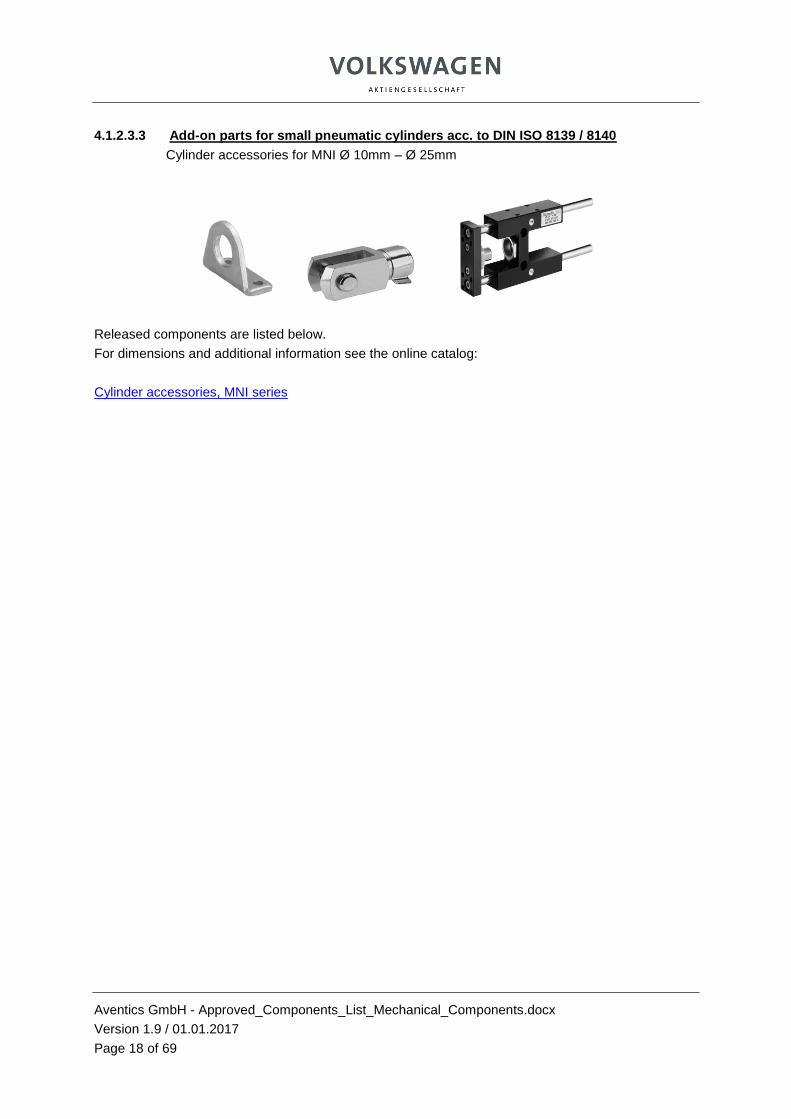
4.1.2.3.3 Add-on parts for small pneumatic cylinders acc. to DIN ISO 8139 / 8140
Cylinder accessories for MNI Ø 10mm – Ø 25mm
Released components are listed below.
For dimensions and additional information see the online catalog:
Cylinder accessories, MNI series

Aventics GmbH - Approved_Components_List_Mechanical_Components.docx
Version 1.9 / 01.01.2017
Page 19 of 69
4.1.2.4 Rodless cylinders Ø 32 mm to Ø 80 mm:
4.1.2.4.1 RTC series – Basic Version
Released components are listed below.
For dimensions and additional information see the online catalog: RTC series
Designation (type) Ø x stroke in
mm Order number Comment
RTC-BV (Basic Version) Ø 32 * 125 Link: Configurator
RTC-BV (Basic Version) Ø 32 * 160 Link: Configurator
RTC-BV (Basic Version) Ø 32 * 200 R480141462
RTC-BV (Basic Version) Ø 32 * 250 Link: Configurator
RTC-BV (Basic Version) Ø 32 *320 Link: Configurator
RTC-BV (Basic Version) Ø 32 * 400 R480141464
RTC-BV (Basic Version) Ø 32 * 500 R480141465
RTC-BV (Basic Version) Ø 32 * 1000 R480141471
RTC-BV (Basic Version) Ø 50 * 125 Link: Configurator
RTC-BV (Basic Version) Ø 50 * 160 Link: Configurator
RTC-BV (Basic Version) Ø 50 * 200 Link: Configurator
RTC-BV (Basic Version) Ø 50 * 250 Link: Configurator
RTC-BV (Basic Version) Ø 50 * 320 Link: Configurator
RTC-BV (Basic Version) Ø 50 * 400 R480148854
RTC-BV (Basic Version) Ø 50 * 500 R480146166
RTC-BV (Basic Version) Ø 50 * 1000 R480149199
RTC-BV (Basic Version) Ø 63 * 125 Link: Configurator
RTC-BV (Basic Version) Ø 63 * 160 Link: Configurator
RTC-BV (Basic Version) Ø 63 * 200 Link: Configurator
RTC-BV (Basic Version) Ø 63 * 250 Link: Configurator
RTC-BV (Basic Version) Ø 63 *320 Link: Configurator
RTC-BV (Basic Version) Ø 63 * 400 R480147730
RTC-BV (Basic Version) Ø 63 * 500 R480147713
RTC-BV (Basic Version) Ø 63 * 1000 R480147036
RTC-BV (Basic Version) Ø 80 * 125 Link: Configurator
RTC-BV (Basic Version) Ø 80 * 160 Link: Configurator
RTC-BV (Basic Version) Ø 80 * 200 Link: Configurator

Aventics GmbH - Approved_Components_List_Mechanical_Components.docx
Version 1.9 / 01.01.2017
Page 20 of 69
RTC-BV (Basic Version) Ø 80 * 250 Link: Configurator
RTC-BV (basic version) Ø 80 *320 Link: Configurator
RTC-BV (Basic Version) Ø 80 * 400 R480147731
RTC-BV (Basic Version) Ø 80 * 500 R480147714
RTC-BV (Basic Version) Ø 80 * 1000 R480147700

Aventics GmbH - Approved_Components_List_Mechanical_Components.docx
Version 1.9 / 01.01.2017
Page 21 of 69
4.1.2.4.2 RTC series – Heavy Duty version
Released components are listed below.
For dimensions and additional information see the online catalog: RTC series
Designation (type) Ø x stroke in
mm Order number Comment
RTC-HD (Heavy Duty) Ø 32 * 125 Link: Configurator
RTC-HD (Heavy Duty) Ø 32 * 160 Link: Configurator
RTC-HD (Heavy Duty) Ø 32 * 200 R480154726
RTC-HD (Heavy Duty) Ø 32 * 250 Link: Configurator
RTC-HD (Heavy Duty) Ø 32 *320 Link: Configurator
RTC-HD (Heavy Duty) Ø 32 * 400 R480148602
RTC-HD (Heavy Duty) Ø 32 * 500 R480147726
RTC-HD (Heavy Duty) Ø 32 * 1000 R480148582
RTC-HD (Heavy Duty) Ø 50 * 125 Link: Configurator
RTC-HD (Heavy Duty) Ø 50 * 160 Link: Configurator
RTC-HD (Heavy Duty) Ø 50 * 200 Link: Configurator
RTC-HD (Heavy Duty) Ø 50 * 250 Link: Configurator
RTC-HD (Heavy Duty) Ø 50 – 320 Link: Configurator
RTC-HD (Heavy Duty) Ø 50 * 400 R480155175
RTC-HD (Heavy Duty) Ø 50 * 500 R480147728
RTC-HD (Heavy Duty) Ø 50 * 1000 R480149030
RTC-HD (Heavy Duty) Ø 63 * 125 Link: Configurator
RTC-HD (Heavy Duty) Ø 63 * 160 Link: Configurator
RTC-HD (Heavy Duty) Ø 63 * 200 Link: Configurator
RTC-HD (Heavy Duty) Ø 63 * 250 Link: Configurator
RTC-HD (Heavy Duty) Ø 63 *320 Link: Configurator
RTC-HD (Heavy Duty) Ø 63 * 400 R480156946
RTC-HD (Heavy Duty) Ø 63 * 500 R480147729
RTC-HD (Heavy Duty) Ø 63 * 1000 R480149031

Aventics GmbH - Approved_Components_List_Mechanical_Components.docx
Version 1.9 / 01.01.2017
Page 22 of 69
4.1.2.4.3 RTC series – Compact Guide version
Released components are listed below.
For dimensions and additional information see the online catalog: RTC series
Designation (type) Ø x stroke in
mm Order number
Comment
RTC-CG (Compact Guide) Ø 32 * 125 Link: Configurator
RTC-CG (Compact Guide) Ø 32 * 160 Link: Configurator
RTC-CG (Compact Guide) Ø 32 * 200 R480154848
RTC-CG (Compact Guide) Ø 32 * 250 Link: Configurator
RTC-CG (Compact Guide) Ø 32 *320 Link: Configurator
RTC-CG (Compact Guide) Ø 32 * 400 R480148680
RTC-CG (Compact Guide) Ø 32 * 500 R480146674
RTC-CG (Compact Guide) Ø 32 * 1000 R480153428
4.1.2.4.4 RTC series – Accessories
All accessory parts for cylinder mounting are released, such as
- End cover mounting
- Foot mounting
- Coupling
- Shock absorber kits
- Connection kits, centering rings, sliding block
Aventics GmbH - Approved_Components_List_Mechanical_Components.docx
Version 1.9 / 01.01.2017
Page 23 of 69
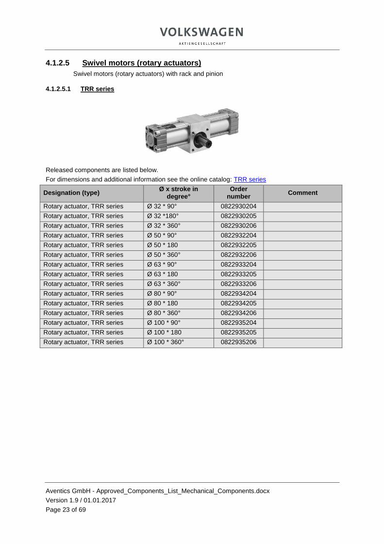
4.1.2.5 Swivel motors (rotary actuators)
Swivel motors (rotary actuators) with rack and pinion
4.1.2.5.1 TRR series
Released components are listed below.
For dimensions and additional information see the online catalog: TRR series
Designation (type) Ø x stroke in
degree° Order
number Comment
Rotary actuator, TRR series Ø 32 * 90° 0822930204
Rotary actuator, TRR series Ø 32 *180° 0822930205
Rotary actuator, TRR series Ø 32 * 360° 0822930206
Rotary actuator, TRR series Ø 50 * 90° 0822932204
Rotary actuator, TRR series Ø 50 * 180 0822932205
Rotary actuator, TRR series Ø 50 * 360° 0822932206
Rotary actuator, TRR series Ø 63 * 90° 0822933204
Rotary actuator, TRR series Ø 63 * 180 0822933205
Rotary actuator, TRR series Ø 63 * 360° 0822933206
Rotary actuator, TRR series Ø 80 * 90° 0822934204
Rotary actuator, TRR series Ø 80 * 180 0822934205
Rotary actuator, TRR series Ø 80 * 360° 0822934206
Rotary actuator, TRR series Ø 100 * 90° 0822935204
Rotary actuator, TRR series Ø 100 * 180 0822935205
Rotary actuator, TRR series Ø 100 * 360° 0822935206

Aventics GmbH - Approved_Components_List_Mechanical_Components.docx
Version 1.9 / 01.01.2017
Page 24 of 69
4.1.2.5.2 RAN series
Swivel motor (rotary wing drive) with swivel wings
Released components are listed below.
For dimensions and additional information see the online catalog: RAN series
Designation (type) Nm, stroke in
degree° Order
number Comment
RAN 1 series rotary wing drive 0.16 Nm, 90° 2650117000
RAN 1 series rotary wing drive 0.16 Nm, 180° 2650117010
RAN 1 series rotary wing drive 0.16 Nm, 270° 2650117020
RAN 3 series rotary wing drive 0.39 Nm, 90° 2650117030
RAN 3 series rotary wing drive 0.39 Nm, 180° 2650117040
RAN 3 series rotary wing drive 0.39 Nm, 270° 2650117050
RAN 8 series rotary wing drive 1.0 Nm, 90° 2650117060
RAN 8 series rotary wing drive 1.0 Nm, 180° 2650117070
RAN 8 series rotary wing drive 1.0 Nm, 270° 2650117080
RAN 20 series rotary wing drive 2.6 Nm, 90° 2650117090
RAN 20 series rotary wing drive 2.6 Nm, 180° 2650117100
RAN 20 series rotary wing drive 2.6 Nm, 270° 2650117110
RAN 50 series rotary wing drive 7.1 Nm, 90° 2650117120
RAN 50 series rotary wing drive 7.1 Nm, 180° 2650117130
RAN 50 series rotary wing drive 7.1 Nm, 275° 2650117140

Aventics GmbH - Approved_Components_List_Mechanical_Components.docx
Version 1.9 / 01.01.2017
Page 25 of 69
4.1.2.6 Compact cylinders ISO 21287 piston rod, Ø 20 mm to Ø 80 mm
4.1.2.6.1 CCI series piston rod with internal thread, Ø 20 mm to Ø 80 mm
Cylinders acc. to ISO 21287
Released components are listed below.
For dimensions and additional information see the online catalog: CCI series
Designation (type) Ø x stroke in mm Order number Comment
CCI series double-acting with internal thread Ø 20 * 10 R422001013
CCI series double-acting with internal thread Ø 20 * 20 R422001033
CCI series double-acting with internal thread Ø 20 * 30 R422001053
CCI series double-acting with internal thread Ø 20 * 40 R422001063
CCI series double-acting with internal thread Ø 20 * 50 R422001073
CCI series double-acting with internal thread Ø 32 * 10 R422001015
CCI series double-acting with internal thread Ø 32 * 20 R422001035
CCI series double-acting with internal thread Ø 32 * 30 R422001055
CCI series double-acting with internal thread Ø 32 * 40 R422001065
CCI series double-acting with internal thread Ø 32 * 50 R422001075
CCI series double-acting with internal thread Ø 50 * 10 R422001017
CCI series double-acting with internal thread Ø 50 * 20 R422001037
CCI series double-acting with internal thread Ø 50 * 30 R422001057
CCI series double-acting with internal thread Ø 50 * 40 R422001067
CCI series double-acting with internal thread Ø 50 * 50 R422001077
CCI series double-acting with internal thread Ø 63 * 10 R422001018
CCI series double-acting with internal thread Ø 63 * 20 R422001038
CCI series double-acting with internal thread Ø 63 * 30 R422001058
CCI series double-acting with internal thread Ø 63 * 40 R422001068
CCI series double-acting with internal thread Ø 63 * 50 R422001078
CCI series double-acting with internal thread Ø 80 * 10 R422001019
CCI series double-acting with internal thread Ø 80 * 20 R422001039
CCI series double-acting with internal thread Ø 80 * 30 R422001059
CCI series double-acting with internal thread Ø 80 * 40 R422001069
CCI series double-acting with internal thread Ø 80 * 50 R422001079

Aventics GmbH - Approved_Components_List_Mechanical_Components.docx
Version 1.9 / 01.01.2017
Page 26 of 69
4.1.2.6.2 CCI series piston rod non-rotating, Ø 20 mm to Ø 80 mm
Cylinders acc. to ISO 21287
Released components are listed below.
For dimensions and additional information see the online catalog: CCI series
Designation (type) Ø x stroke in
mm Order number Comment
Series CCI double-acting, non-rotating Ø 20 * 10 R422001273
Series CCI double-acting, non-rotating Ø 20 * 20 R422001293
Series CCI double-acting, non-rotating Ø 20 * 30 R422001313
Series CCI double-acting, non-rotating Ø 20 * 40 R422001323
Series CCI double-acting, non-rotating Ø 20 * 50 R422001333
Series CCI double-acting, non-rotating Ø 32 * 10 R422001275
Series CCI double-acting, non-rotating Ø 32 * 20 R422001295
Series CCI double-acting, non-rotating Ø 32 * 30 R422001315
Series CCI double-acting, non-rotating Ø 32 * 40 R422001325
Series CCI double-acting, non-rotating Ø 32 * 50 R422001335
Series CCI double-acting, non-rotating Ø 50 * 10 R422001277
Series CCI double-acting, non-rotating Ø 50 * 20 R422001297
Series CCI double-acting, non-rotating Ø 50 * 30 R422001317
Series CCI double-acting, non-rotating Ø 50 * 40 R422001327
Series CCI double-acting, non-rotating Ø 50 * 50 R422001337
Series CCI double-acting, non-rotating Ø 63 * 10 R422001278
Series CCI double-acting, non-rotating Ø 63 * 20 R422001298
Series CCI double-acting, non-rotating Ø 63 * 30 R422001318
Series CCI double-acting, non-rotating Ø 63 * 40 R422001328
Series CCI double-acting, non-rotating Ø 63 * 50 R422001338
Series CCI double-acting, non-rotating Ø 80 * 10 R422001279
Series CCI double-acting, non-rotating Ø 80 * 20 R422001299
Series CCI double-acting, non-rotating Ø 80 * 30 R422001319
Series CCI double-acting, non-rotating Ø 80 * 40 R422001329
Series CCI double-acting, non-rotating Ø 80 * 50 R422001339
Aventics GmbH - Approved_Components_List_Mechanical_Components.docx
Version 1.9 / 01.01.2017
Page 27 of 69
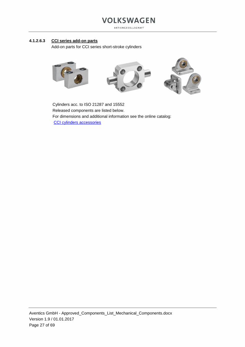
4.1.2.6.3 CCI series add-on parts
Add-on parts for CCI series short-stroke cylinders
Cylinders acc. to ISO 21287 and 15552
Released components are listed below.
For dimensions and additional information see the online catalog:
CCI cylinders accessories

______________________________________________________________________________________________________
Aventics GmbH - Approved_Components_List_Mechanical_Components.docx
Version 1.9 / 01.01.2017
Page 28 of 69
4.2 Energy control and regulation
4.2.1 Directional valves and accessories
4.2.1.1 Directional valves, electromagnetically operated
4.2.1.2 3/2 directional valves, electromagnetically operated
Directional valves
Released components are listed below.
For dimensions and additional information please get in touch with your Aventics contact.
Designation (type) Dimensions Order number Comment
CNOMO pilot valve,
flange-mountable
M12 connection
0820019530 24 V MO single solenoid
CNOMO basic valve
flange-mountable No coil 1825500979
Can be equipped with coil 1824210354
M12
CNOMO control valve
flange-mountable *) No coil 5420855302
Can be equipped with coil 24 VDC 5420857022
220 VAC 5428157082
Coil 24 VDC M12 connection
1824210354
Coil for CNOMO basic valve
1825500979
Shut-off valve AS2 G1/4 R412006258
Without CNOMO pilot valve
Use silencer R412004817
Shut-off valve AS3 G1/2 R412007259 Without CNOMO pilot valve
Shut-off valve AS5 G1 R412009259 Without CNOMO pilot valve
*) As a replacement for installed valves with CNOMO pilot valve and electric connection according to form A DIN
Aventics GmbH - Approved_Components_List_Mechanical_Components.docx
Version 1.9 / 01.01.2017
Page 29 of 69
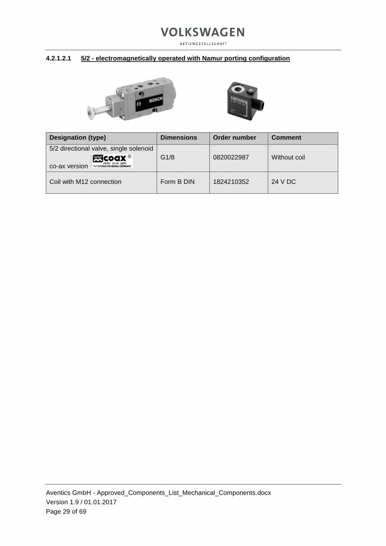
4.2.1.2.1 5/2 - electromagnetically operated with Namur porting configuration
Designation (type) Dimensions Order number Comment
5/2 directional valve, single solenoid
co-ax version
G1/8 0820022987 Without coil
Coil with M12 connection Form B DIN 1824210352 24 V DC

Aventics GmbH - Approved_Components_List_Mechanical_Components.docx
Version 1.9 / 01.01.2017
Page 30 of 69
4.2.1.2.2 Pneumatically operated and time switching valve
Released components are listed below.
For dimensions and additional information please get in touch with your Aventics contact.
Designation (type) Dimensions Order number Comment
Shut-off valve, AS2 series R412006262 Use silencer R412004817
Shut-off valve, AS3 series R412007263
Shut-off valve, AS5 series R412009263
Filling valve AS2 R412006272
Filling valve AS3 R412007273
Filling valve AS5 R412009273
Time switching valve 1-99999 min M 5 0820215113
5-digit, use for filling units, item 4.2.1.2.3, and others
4.2.1.2.3 Cleaning pressure modules
Designation (type) Dimensions Order number Comment
Filing unit with CD01 valves
and time switching valve, item 4.2.1.2.2
Connections G1/4
R416005016 Valves according to
ISO 15407-1
Filling unit with 581 series valves
and time switching valve, item 4.2.1.2.2
Connections G1/4
R416005017 Valves according to
ISO 5599-1 size 1
Filling unit with 581 series valves
and time switching valve, item 4.2.1.2.2
Connections G1/2
R416005018 Valves according to
ISO 5599-1 size 3

Aventics GmbH - Approved_Components_List_Mechanical_Components.docx
Version 1.9 / 01.01.2017
Page 31 of 69
4.2.1.2.4 Mechanically (manually) operated
3/2 directional valves, mechanically (manually) operated
with actuating elements, mechanically & manually operated
Released components are listed below.
For additional information please get in touch with your Aventics contact.
AP series 3/2 valves
Designation (type) Dimensions Order number Comment
AP series with plunger 3/2 directional G1/4, NG6 0820400001 Basic valve
Roller, actuating elements for valve specified above * 2827030002
Data available on request
Roller lever with one-way trip, actuating elements for valve specified above * 2827030003
Data available on request
3/2 valve AS2 G1/4 R412006256 Lockable
3/2 valve AS3 G1/2 R412007261 Lockable
3/2 valve AS5 G1 R412009261 Lockable
Complete valves with actuating elements can be found in the above “AP series” link.
4/2 directional valves, mechanically (manually) operated
with actuating elements, mechanically & manually operated
Released components are listed below.
For dimensions and additional information see the online catalog: AP series 4/2 valves
Designation (type) Dimensions Order number Comment
AP series with plunger 4/2 directional G1/4, NG6 0820401001 Basic valve
Roller, actuating elements for valve specified above * 2827030006
Data available on request
Roller lever with one-way trip, actuating elements for valve specified above * 2827030007
Data available on request
Push button, actuating elements for valve specified above * 2827030008
Data available on request
Lever, actuating elements for valve specified above * 2827030009
Data available on request
Complete valves with actuating elements can be found in the above “AP series” link.

Aventics GmbH - Approved_Components_List_Mechanical_Components.docx
Version 1.9 / 01.01.2017
Page 32 of 69
4.2.1.3 5/2 and 5/3 directional valves acc. to ISO 5599-1
4.2.1.3.1 Size 1, electrically operated
Directional valves acc. to ISO 5599-1
Released components are listed below.
For dimensions and additional information see the online catalog: 581 series
Maximum six pneumatic valves with hole pattern acc. to ISO 5599-1
Slide valves must be installed in the horizontal slide axis position in accordance with the VW specification Mechanics 4.3.4.1
Designation (type) Dimensions Order number Comment
Sealing caps for manual override, bag of 10 8980122904 For contact
bridge
581 series, 5/2 directional valve ISO 1, 24 V 5811260130 Double
solenoid
581 series, 5/2 directional valve ISO 1, 24 V R404064741
Double solenoid with
differential piston
581 series, 5/3 directional valve, pressurized center ISO 1, 24 V 5811760130
581 series, 5/3 directional valve, exhausted center ISO 1, 24 V 5811560130
Contact bridge M12x1 for 581 series double solenoid M12x1 5763573103
Remove pin 3 from the pilot before fitting the contact bridge
Aventics GmbH - Approved_Components_List_Mechanical_Components.docx
Version 1.9 / 01.01.2017
Page 33 of 69
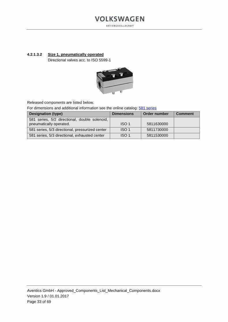
4.2.1.3.2 Size 1, pneumatically operated
Directional valves acc. to ISO 5599-1
Released components are listed below.
For dimensions and additional information see the online catalog: 581 series
Designation (type) Dimensions Order number Comment
581 series, 5/2 directional, double solenoid, pneumatically operated. ISO 1 5811630000
581 series, 5/3 directional, pressurized center ISO 1 5811730000
581 series, 5/3 directional, exhausted center ISO 1 5811530000

Aventics GmbH - Approved_Components_List_Mechanical_Components.docx
Version 1.9 / 01.01.2017
Page 34 of 69
4.2.1.3.3 Size 3, electrically operated
Directional valves acc. to ISO 5599-1
Released components are listed below.
For dimensions and additional information see the online catalog: 581 series
Designation (type) Series Order number Comment
581 series, 5/2 directional basic valve
ISO 3,
CNOMO 5813680000
Single solenoid with
differential piston
581 series, 5/2 directional basic valve ISO 3,
CNOMO 5813680000
Double solenoid with
differential piston
581 series, 5/3 directional basic valve ISO 3,
CNOMO 5813780000 Pressurized center
581 series, 5/3 directional basic valve ISO 3,
CNOMO 5813580000 Exhausted center
CNOMO pilot valve for basic valves DO 0820019530 Incl. M12
24 V DC coil
581 series, 5/2 directional, air spring ISO 3,
CNOMO 5813670530
Single solenoid, differential piston, electr. connection, form A DIN
581 series, 5/2 directional ISO 3,
CNOMO R402001743
Double solenoid, differential piston, electr. connection, form A DIN
581 series, 5/3 directional ISO 3,
CNOMO 5813790530
Pressurized center, electr. connection, form A DIN
581 series, 5/3 directional ISO 3,
CNOMO 5813590530
Exhausted center, electr. connection, form A DIN
Coil CO1 1824210354 Replacement coil, M12 24 V DC
Coil CO1 5420857022
Replacement coil, form A DIN
24 V DC
Size 3 transition plates are mounted to the valves of the 581 series ISO valves.
Form A DIN for replacement and after consulting with the planner.

Aventics GmbH - Approved_Components_List_Mechanical_Components.docx
Version 1.9 / 01.01.2017
Page 35 of 69
Size 3 pneumatically operated
Directional valves acc. to ISO 5599-1
Released components are listed below.
For dimensions and additional information see the online catalog: 581 series
Designation (type) Dimensions Order number Comment
581 series, 5/2 directional, double solenoid ISO 3 5813630000
581 series, 5/3 directional, pressurized center ISO 3 5813730000
581 series, 5/3 directional, exhausted center ISO 3 5813530000
4.2.1.4 Accessories for directional valves acc. to ISO 5599-1
Accessories acc. to ISO 5599-1 & VDMA 24345
4.2.1.4.1 Single subbases, ports on side, VDMA 24345 A…G
Released components are listed below.
For dimensions and additional information see the online catalog: ISO 5599-1
Designation (type) Series Order number Comment
Single subbases form A Size 1 1825503143
Single subbases form A Size 3 1825503149

Aventics GmbH - Approved_Components_List_Mechanical_Components.docx
Version 1.9 / 01.01.2017
Page 36 of 69
4.2.1.4.2 Single subbases, ports on bottom, VDMA 24345 A…G
Released components are listed below.
For dimensions and additional information see the online catalog: ISO 5599-1
Designation (type) Series Order number Comment
Single subbases form B Size 1 1825503201
Single subbases form B Size 3 1825503203
4.2.1.4.3 Sandwich plates, working connections on bottom, VDMA 24345 C…G
Released components are listed below.
For dimensions and additional information see the online catalog: ISO 5599-1
Designation (type) Series Order number Comment
Sandwich plates form C Size 1 1825503144
Sandwich plates form C Size 3 1825503150

Aventics GmbH - Approved_Components_List_Mechanical_Components.docx
Version 1.9 / 01.01.2017
Page 37 of 69
4.2.1.4.4 End plate kits VDMA 24345 D…G
Released components are listed below.
For dimensions and additional information see the online catalog: ISO 5599-1
Designation (type) Series Order number Comment
End plate kits form DA and DB Size 1 1825503145
End plate kits form DA and DB Size 3 1825503151
4.2.1.4.5 Angle subbases VDMA 24345 E
Angle subbases with connections for differential pressure switch VDMA 24345 form E
Released components are listed below.
For dimensions and additional information see the online catalog: ISO 5599-1
Designation (type) Series Order number Comment
Angle subbases Size 1 1825503324
Angle subbases Size 3 1825503764

Aventics GmbH - Approved_Components_List_Mechanical_Components.docx
Version 1.9 / 01.01.2017
Page 38 of 69
4.2.1.4.6 Blanking plates
Released components are listed below.
For dimensions and additional information see the online catalog: ISO 5599-1
Designation (type) Series Order number Comment
Blanking plates Size 1 1825503282
Blanking plates Size 3 1825503174
4.2.1.4.7 Throttle plates
Released components are listed below.
For dimensions and additional information see the online catalog: ISO 5599-1
Designation (type) Series Order number Comment
Throttle plates Size 1 0821201023
Throttle plates Size 3 0821201025

Aventics GmbH - Approved_Components_List_Mechanical_Components.docx
Version 1.9 / 01.01.2017
Page 39 of 69
4.2.1.5 5/2 and 5/3 directional valves acc. to ISO 15407-1, VDMA 24563
Directional valves & accessories acc. to ISO 15407-1 VDMA 24563
4.2.1.5.1 Directional valves, electrically operated with M12 connection
Directional valves, electrically operated with M12 connection
Released components are listed below.
For dimensions and additional information see the online catalog: ISO 15407-1
Maximum eight pneumatic valves with hole pattern acc. to ISO 15407-1
Designation (type) Series Order number Comment
Sealing caps for manual override, bag of 10 * 8980122904
For contact bridge
CD01 PA series, double 3/2 directional valve. MO without detent VDMA01, 26 mm 5763970620
Normally open valves,
pressurized
CD01 PA series , 5/2 directional valve, MO without detent VDMA01, 26 mm 5763510620
Single solenoid
No movement during
emergency OFF allowed!
CD01 PA series, 5/2 directional valve, MO without detent VDMA01, 26 mm 5763530620
Double solenoid
CD01 PA series, 5/3 directional valve, MO without detent VDMA01, 26 mm 5763800920
Pressurized center
CD01 PA series, 5/3 directional valve, MO without detent VDMA01, 26 mm 5763810920
Exhausted center
Aventics GmbH - Approved_Components_List_Mechanical_Components.docx
Version 1.9 / 01.01.2017
Page 40 of 69
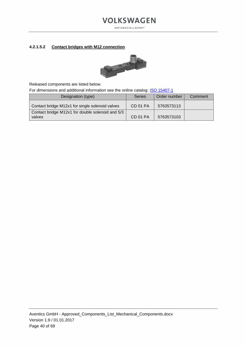
4.2.1.5.2 Contact bridges with M12 connection
Released components are listed below.
For dimensions and additional information see the online catalog: ISO 15407-1
Designation (type) Series Order number Comment
Contact bridge M12x1 for single solenoid valves CD 01 PA 5763573113
Contact bridge M12x1 for double solenoid and 5/3 valves CD 01 PA 5763573103

Aventics GmbH - Approved_Components_List_Mechanical_Components.docx
Version 1.9 / 01.01.2017
Page 41 of 69
4.2.1.5.3 Pneumatically operated directional valves
Released components are listed below.
For dimensions and additional information see the online catalog: ISO 15407-1
Designation (type) Series Order number Comment
CD01 series, double 3/2 directional valve, pressurized VDMA01, 26 mm 5714003990
CD01 series, 5/2 directional valve, double solenoid VDMA01, 26 mm 5714003530
CD01 series, 5/3 directional valve, pressurized center VDMA01, 26 mm 5714003800
CD01 series, 5/3 directional valve, exhausted center VDMA01, 26 mm 5714003810

Aventics GmbH - Approved_Components_List_Mechanical_Components.docx
Version 1.9 / 01.01.2017
Page 42 of 69
4.2.1.5.4 Subbases acc. to ISO 15407-1
Released components are listed below.
For dimensions and additional information see the online catalog: ISO 15407-1
Designation (type) Dimensions Order number Comment
Single subbase G1/4 1825504016
Sandwich base G1/4 1825504026
End plate kit G3/8 1825504031
Blanking plate 26 mm 1825504033
Mounting kit for rail EN 50 022 26 mm 1821398007

Aventics GmbH - Approved_Components_List_Mechanical_Components.docx
Version 1.9 / 01.01.2017
Page 43 of 69
4.2.2 Valve systems – VS
4.2.2.1 VS series AV03 300 l/min
4.2.2.1.1 Valves and plates
For dimensions and additional information see the online catalog: AV03
Maximum 12 valve positions, restricted exhaust, Installation place and position freely selectable
For information about the configurator see 4.2.2.5
Designation (type) Order number Comment
5/2 directional valve, air spring R422102504 Single solenoid
5/2 valve R422102427 Pulse valve
2x 3/2 directional valve NC/NC R422102431 Mech. spring*)
2x 3/2 directional valve NO/NO R422102433 Mech. spring*)
Blanking plate R422102462 Incl. sealing kit and 1x mounting screw
Accessories Item 4.2.2.4
*) Use valve with spring return only as 5/3 function
Aventics GmbH - Approved_Components_List_Mechanical_Components.docx
Version 1.9 / 01.01.2017
Page 44 of 69
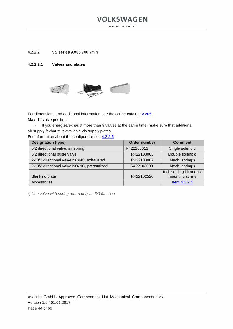
4.2.2.2 VS series AV05 700 l/min
4.2.2.2.1 Valves and plates
For dimensions and additional information see the online catalog: AV05
Max. 12 valve positions
- If you energize/exhaust more than 8 valves at the same time, make sure that additional
air supply /exhaust is available via supply plates.
For information about the configurator see 4.2.2.5
Designation (type) Order number Comment
5/2 directional valve, air spring R422103013 Single solenoid
5/2 directional pulse valve R422103003 Double solenoid
2x 3/2 directional valve NC/NC, exhausted R422103007 Mech. spring*)
2x 3/2 directional valve NO/NO, pressurized R422103009 Mech. spring*)
Blanking plate R422102526 Incl. sealing kit and 1x
mounting screw
Accessories Item 4.2.2.4
*) Use valve with spring return only as 5/3 function

Aventics GmbH - Approved_Components_List_Mechanical_Components.docx
Version 1.9 / 01.01.2017
Page 45 of 69
4.2.2.3 Bus coupler for AV03 and AV05
1 2
4.2.2.3.1 ProfiNet IO, Profibus DP
For information about the configurator see 4.2.2.5
Designation (type) Order number Comment
Bus coupler Profibus DP 1) R412018218 Sub-buses are not allowed
Bus coupler ProfiNet IO 1) R412018223 Sub-buses are not allowed
Power module 7/8" actuator + logic voltage 2) R412018272
For linking to bus coupler
W 50 x L 82 x H 34
Cover cap for bus coupler power connection Available in configured unit
Further accessories Item 4.2.2.4
Power modules for additional UA or UL supply in the I/O area are available, to be used if required in coordination with the project planner of the VW Group.
4.2.2.3.2 Input modules
Designation (type)
Order number Comment
Digital input module 8 DI with 8DI4M12
4x M12x1 5-pin
R412018235
Max. 3 modules
for recording the end positions of actuators of the respective valve unit
Accessories Item 4.2.2.4

Aventics GmbH - Approved_Components_List_Mechanical_Components.docx
Version 1.9 / 01.01.2017
Page 46 of 69
4.2.2.4 VS – Accessories
The following have been released:
- Expansion base plates, end plates
- Extension kits, pneumatic supply and exhaust modules, pressure zones
- AV03/05 combination plate
- Silencer for restricted exhaust
- Push-in fittings
- VS mounting, labels, protective cap, pn. connections and seals
- El. connections for bus coupler and for the M12 input module
Acc. to the online catalog o For AV03 o For AV05
Accessory components included in the online catalog, but not listed under 4.2.2.4
Only in coordination with your Aventics contact and the project planner
of the VW Group via special approval.

Aventics GmbH - Approved_Components_List_Mechanical_Components.docx
Version 1.9 / 01.01.2017
Page 47 of 69
4.2.2.5 Configurator
Notes regarding configuration:
- Selection AV03 or AV05 > - Fieldbus connection ProfibusDP or ProfiNetIO > - Metric connection, internal pilot air supply,
Straight fittings > - Add I/O- module
o Choose POWER1-7/8-AL > - If required, add max. 3 I/O modules 8DI4M12 >
- Click on the input module – configuration o Exhaust module restricted exhaust 3/5 >>
- Click on the 1st valve position o Select the valve (subsequently optional/supply plate if required) o Valve
5/2 single solenoid, air return Double solenoid 2x 3/2 normally closed (use only as 5/3 function) 2x 3/2 normally open (use only as 5/3 function)
Manual override (MO) each, without detent
Select fitting size 2, 4 > , or return to the configuration >>
o Copy the valve position to right/left, or click on the valve position and select Function type
Valve/supply plate o Supply plate – exhaust module restricted exhaust 3/5
Configuration (valve type and MO as described above) Accessories (fittings 2 , 4 – pre-select 8 for AV05; 6 for AV03)
After completion of the configuration with max. 12 valve positions and 3 I/O modules click on the configuration documentation on the right side in the configurator and download it.
VS are currently configurable for power connection M12. Material numbers and dimensioned drawings with 7/8“ power connection based on the created configuration are available from your Aventics contact.

Aventics GmbH - Approved_Components_List_Mechanical_Components.docx
Version 1.9 / 01.01.2017
Page 48 of 69
4.2.3 Blocking valves
4.2.3.1 Non-return valves
NR01 non-return valves series with internal thread
Released components are listed below.
For dimensions and additional information see the online catalog: NR01 series
Designation (type) Dimensions Order number Comment
NR01 series G1/8 5340981000
NR01 series G1/4 5340981100
NR01 series G1/2 5340981300
NR01 series G1 5340970300
4.2.3.2 Pilot-operated non-return valves and manual exhaust
NR02 series pilot-operated valves and manual exhaust
Released components are listed below.
For dimensions and additional information see the online catalog: NR02 series
Designation (type) Dimensions Order number Comment
NR02 series G1/8 0821003045
NR02 series G1/4 0821003046
NR02 series G3/8 0821003047
NR02 series G1/2 0821003048

Aventics GmbH - Approved_Components_List_Mechanical_Components.docx
Version 1.9 / 01.01.2017
Page 49 of 69
Pilot-operated non-return valves must be approved – see VW functional requirements for mechanical components, item 4.3.5

Aventics GmbH - Approved_Components_List_Mechanical_Components.docx
Version 1.9 / 01.01.2017
Page 50 of 69
4.2.3.3 Double check valves
Released components are listed below.
For dimensions and additional information please get in touch with your Aventics contact..
OR shuttle valves
Designation (type) Dimensions Order number Comment
Double check valve (OR) G1/8 0821000002 Shuttle valve
Double check valve (OR) G1/4 0821000003 Shuttle valve
Double check valve (OR) G1/2 0821000011 Shuttle valve
4.2.3.4 Quick exhaust valves
573 series quick exhaust valves with internal thread
Released components are listed below.
For dimensions and additional information see the online catalog: 573 series
Designation (type) Dimensions Order number Comment
573 series G1/8 5735040000
573 series G1/4 5735040100
573 series G1/2 5735040300
4.2.3.5 Twin pressure valves
Released components are listed below.
For dimensions and additional information see the online catalog: Twin pressure valve
Designation (type) Dimensions Order number Comment
Twin pressure valve (AND) G1/8 0821001003 NG4
Twin pressure valve (AND) G1/4 0821001002 NG6

Aventics GmbH - Approved_Components_List_Mechanical_Components.docx
Version 1.9 / 01.01.2017
Page 51 of 69
4.2.4 Pressure valves
4.2.5 Flow control valves
4.2.5.2 Throttle valve
Released components are listed below.
For dimensions and additional information see the online catalog: CH01 series
Designation (type) Dimensions Order number Comment
CH01 series G1/4 0821201011 NG6
4.2.5.3 Check-choke valves
4.2.5.3.1 Manually adjustable with internal thread
Released components are listed below.
For dimensions and additional information see the online catalog: Series CC01
Designation (type) Dimensions Order number Comment
CC01 series G1/8 0821200008 Throttling 1 2
CC01 series G1/4 0821200005 Throttling 1 2
CC01 series G3/8 0821200014 Throttling 1 2
CC01 series G1/2 0821200003 Throttling 1 2
CC01 series G3/4 0821200015 Throttling 1 2
Aventics GmbH - Approved_Components_List_Mechanical_Components.docx
Version 1.9 / 01.01.2017
Page 52 of 69
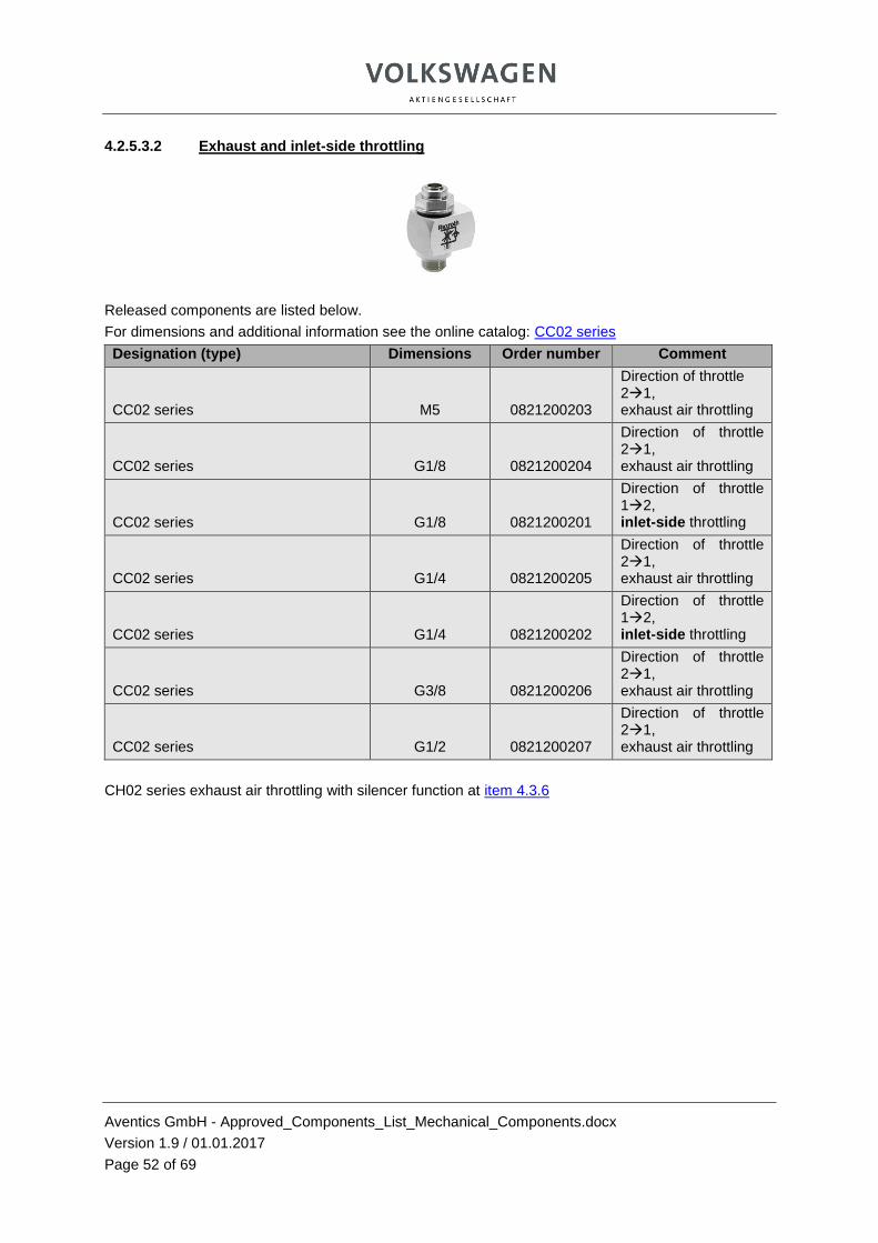
4.2.5.3.2 Exhaust and inlet-side throttling
Released components are listed below.
For dimensions and additional information see the online catalog: CC02 series
Designation (type) Dimensions Order number Comment
CC02 series M5 0821200203
Direction of throttle 21, exhaust air throttling
CC02 series G1/8 0821200204
Direction of throttle 21, exhaust air throttling
CC02 series G1/8 0821200201
Direction of throttle 12, inlet-side throttling
CC02 series G1/4 0821200205
Direction of throttle 21, exhaust air throttling
CC02 series G1/4 0821200202
Direction of throttle 12, inlet-side throttling
CC02 series G3/8 0821200206
Direction of throttle 21, exhaust air throttling
CC02 series G1/2 0821200207
Direction of throttle 21, exhaust air throttling
CH02 series exhaust air throttling with silencer function at item 4.3.6

Aventics GmbH - Approved_Components_List_Mechanical_Components.docx
Version 1.9 / 01.01.2017
Page 53 of 69
4.3 Energy transmission
4.3.1 Tubing and tubing connections
TU1 P-S PA polyamide series
Flexible tubing (semi-rigid plastic tubing) for air
External calibrated
Released components are listed below.
For dimensions and additional information see the online catalog: TU1 P-S series
Designation (type) Dimensions Order number Comment
TU1 P-S series 4 x 1; 25 m 1820712100 Colorless
TU1 P-S series 4 x 1; 25 m R412009913 Blue
TU1 P-S series 6 x 1; 25 m 1820712101 Colorless
TU1 P-S series 6 x 0.65; 25 m R412009915 Blue
TU1 P-S series 8 x 1; 25 m 1820712102 Colorless
TU1 P-S series 8 x 1; 25 m R412007590 Blue
TU1 P-S series 10 x 1; 25 m 1820712105 Colorless
TU1 P-S series 10 x 1; 25 m R412009921 Blue
TU1 P-S series 12 x 1.5; 25 m 1820712103 Colorless
TU1 P-S series 12 x 1.1; 25 m R412009924 Blue
TU1P -S series 14 x 1.5; 25 m 1820712104 Colorless
TU1P -S series 14 x 1.25; 25 m R412009927 Blue
TU1P -S series 16 x 1.35; 25 m R412009929 Blue

Aventics GmbH - Approved_Components_List_Mechanical_Components.docx
Version 1.9 / 01.01.2017
Page 54 of 69
TU1-S series polyester polyurethane for air
External calibrated
Suitable for dynamic laying
Halogen-free
Released components are listed below.
For dimensions and additional information see the online catalog: TU1-S series
Designation (type) Dimensions Order number Comment
TU1-S series 4 x 0.75; 50 m R412014554 Colorless
TU1-S series 4 x 0.75; 50 m R412009985 Blue
TU1-S series 6 x 1.05; 50 m R412014556 Colorless
TU1-S series 6 x 1.05; 50 m R412009988 Blue
TU1-S series 8 x 1.15; 50 m R412014557 Colorless
TU1-S series 8 x 1.15; 50 m R412009990 Blue
TU1-S series 10 x 1.25; 50 m R412014558 Colorless
TU1-S series 10 x 1.25; 50 m R412009991 Blue
TU1-S series 12 x 1.5; 50 m R412014559 Colorless
TU1-S series 12 x 1.5; 50 m R412009992 Blue
TU1-S series 14 x 2; 25 m R412004790 Colorless
TU1-S series 14 x 2; 25 m R412004782 Blue
TU1-S series 16 x 2.5; 25 m R412004792 Colorless
TU1-S series 16 x 2.5; 25 m R412004784 Blue
Aventics GmbH - Approved_Components_List_Mechanical_Components.docx
Version 1.9 / 01.01.2017
Page 55 of 69
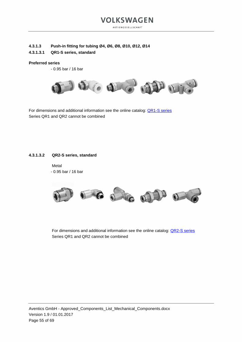
4.3.1.3 Push-in fitting for tubing Ø4, Ø6, Ø8, Ø10, Ø12, Ø14
4.3.1.3.1 QR1-S series, standard
Preferred series
- 0.95 bar / 16 bar
For dimensions and additional information see the online catalog: QR1-S series
Series QR1 and QR2 cannot be combined
4.3.1.3.2 QR2-S series, standard
Metal
- 0.95 bar / 16 bar
For dimensions and additional information see the online catalog: QR2-S series
Series QR1 and QR2 cannot be combined

Aventics GmbH - Approved_Components_List_Mechanical_Components.docx
Version 1.9 / 01.01.2017
Page 56 of 69
4.3.1.4 Filters and filter regulators
For dimensions and additional information please get in touch with your Aventics contact.
AS series active carbon filters of the micorfilter unit (item 5.1.1)
Designation (type) Dimensions
Order number
Comment
5 µ filter
AS2 series
For G1/4
R415017490
Manual condensate drain
5 µ filter
AS3 series
For G1/2
R415017491
Manual condensate drain
5 µ filter
AS5 series For G1 R415017492
Manual condensate drain
0.01 µ filter
AS2 series
For G1/4
R415017493 Microfilter
Manual condensate drain
0.01 µ filter
AS3 series
For G1/2
R415017494 Microfilter
Manual condensate drain
0.01 µ filter
AS5 series For G1 R415017495
Microfilter
Manual condensate drain
25 µ filter regulator,
AS2 series
without E11 locking
For G1/4
R415017496
Manual condensate drain
25 µ filter regulator,
AS3 series
without E11 locking
For G1/2
R415017497 Manual condensate drain
25 µ filter regulator
AS5 series
without
E11 locking
For G1 R415017498 Manual condensate drain

Aventics GmbH - Approved_Components_List_Mechanical_Components.docx
Version 1.9 / 01.01.2017
Page 57 of 69
4.3.4 Pressure regulators
4.3.4.1 Manually adjustable
4.3.4.1.1 Without E11 locking with lockable handwheel (without lock)
Released components are listed below.
For dimensions and additional information please get in touch with your Aventics contact..
Designation (type) Dimensi
on Order number Comment
AS2 series pressure valve without
E11 locking G1/4 R412006108 AS2
AS3 series pressure valve without
E11 locking G1/2 R412007120 AS3
AS5 series pressure valve without
E11 locking G1 R412009120 AS5
Accessories
4.3.4.1.2 Manually adjustable, with E11 locking
Only as spare parts.
From version 1.7, section 4.3.2 (E11 locking)
was deleted from the functional requirements for mechanical components.
Designation (type) Dimensions Order number Comment
AS2 E11
with
E11 locking G1/4 R412006099 AS2
AS3 E11
with
E11 locking G1/2 R412007099 AS3
AS5 E11
with
E11 locking
G1 R412009099 AS5

Aventics GmbH - Approved_Components_List_Mechanical_Components.docx
Version 1.9 / 01.01.2017
Page 58 of 69
4.3.4.1.3 Precision pressure regulator, manually adjustable
Released components are listed below.
For dimensions and additional information see the online catalog: PR1-RGP series
Designation (type) Dimensions Order number Comment
Precision pressure regulator G1/2 0.05 – 7 bar 0821302173 Without pressure
gauge
Precision pressure regulator G1/4 0.05 – 5 bar 0821302566 Without pressure
gauge
Precision pressure regulator G1/4 0.05 – 3 bar 0821302565 Without pressure
gauge
4.3.5 Maintenance units from stand-alone devices
Series AS2; AS3; AS5
For details regarding the maintenance units see section 4.5
Released components are listed below.
Fully assembled maintenance units with manual condensate drain
Designation (type) Dimensions Order
number Comment
AS2 series without sealing air G1/4 R415012940
AS2 series with sealing air, elec., without timer
G1/4 R415012941
AS2 series with sealing air, pneumatic, with timer
G1/4 R415012942
AS3 series without sealing air G1/2 R415012943
AS3 series with sealing air, elec., without timer
G1/2 R415012944
AS3 series with sealing air, pneumatic, with timer
G1/2 R415012945
AS5 series without sealing air G1 R415012946
AS5 series with sealing air, elec., without timer
G1 R415012947
AS5 series with sealing air, pneumatic, with timer
G1 R415012948
AS2 series
sealing air module, fully assembled G1/4 R415012938 For AS2, 3, 5
Regulator 0.2-4 bar
Aventics GmbH - Approved_Components_List_Mechanical_Components.docx
Version 1.9 / 01.01.2017
Page 59 of 69
(regulator, distributor, pressure switch) lockable with lock
AS2 ultrafilter unit, fully assembled, with manual condensate drain
G1/4 R480311490
Details item 5.1.1
Regulator 0.2-4 bar lockable with lock
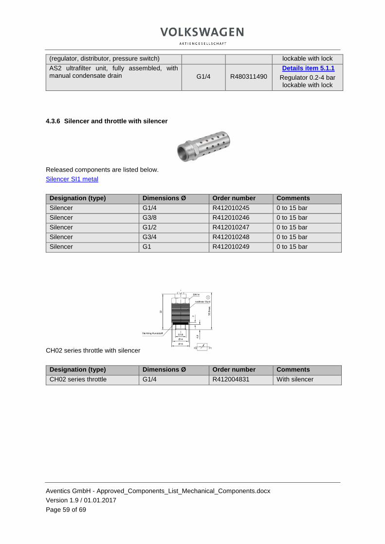
4.3.6 Silencer and throttle with silencer
Released components are listed below.
Silencer SI1 metal
Designation (type) Dimensions Ø Order number Comments
Silencer G1/4 R412010245 0 to 15 bar
Silencer G3/8 R412010246 0 to 15 bar
Silencer G1/2 R412010247 0 to 15 bar
Silencer G3/4 R412010248 0 to 15 bar
Silencer G1 R412010249 0 to 15 bar
CH02 series throttle with silencer
Designation (type) Dimensions Ø Order number Comments
CH02 series throttle G1/4 R412004831 With silencer

Aventics GmbH - Approved_Components_List_Mechanical_Components.docx
Version 1.9 / 01.01.2017
Page 60 of 69
4.4. Additional equipment
4.4.1 PG1-SNL-ADJ series and SAS-ADJ series pressure gauges
Released components are listed below.
For dimensions and additional information see the online catalog:
PG1-SNL-ADJ series
PG1-SAS-ADJ series
Designation (type) Dimensions Order number Comment
Pressure gauge 50 Ø housing G1/8; 0 – 4 bar 1827231077
Pressure gauge 50 Ø housing G1/8; 0-10 bar 1827231079
Pressure gauge 50 Ø housing G1/4; 0 – 4 bar R412003476
Pressure gauge 50 Ø housing G1/4; 0 – 10 bar R412003478
Pressure gauge 50 Ø housing G1/4; 0 – 4 bar R412007869
Only AS series
Pressure gauge 50 Ø housing G1/4; 0 – 6 bar R412007870
Only AS series
Pressure gauge 50 Ø housing G1/4; 0 – 10 bar R412007871
Only AS series
Pressure gauge 50 Ø housing G1/4; 0-12 bar R412007871
Only AS series

Aventics GmbH - Approved_Components_List_Mechanical_Components.docx
Version 1.9 / 01.01.2017
Page 61 of 69
4.4.2 PM1 series mechanical pressure switch, setting range 0.5 bar to 16 bar
For dimensions and additional information see the online catalog: PM1 series
The mechanical pressure switch is only approved in maintenance units. For approved electronic pressure switch see the functional requirements for mechanical components
Designation (type) Dimensions Order number Comment
Pressure switch M12x1 acc. to EN 50 044 G¼, 0.5–16 bar R412010717
Plus 1 unit 1823391017
or 1823391254
Aventics GmbH - Approved_Components_List_Mechanical_Components.docx
Version 1.9 / 01.01.2017
Page 62 of 69
4.5. Other energy control and regulation
5.1. Maintenance units
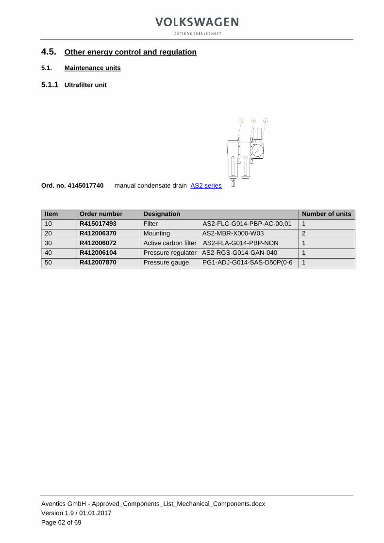
5.1.1 Ultrafilter unit
Ord. no. 4145017740 manual condensate drain AS2 series
Item Order number Designation Number of units
10 R415017493 Filter AS2-FLC-G014-PBP-AC-00,01 1
20 R412006370 Mounting AS2-MBR-X000-W03 2
30 R412006072 Active carbon filter AS2-FLA-G014-PBP-NON 1
40 R412006104 Pressure regulator AS2-RGS-G014-GAN-040 1
50 R412007870 Pressure gauge PG1-ADJ-G014-SAS-D50P(0-6 1
Aventics GmbH - Approved_Components_List_Mechanical_Components.docx
Version 1.9 / 01.01.2017
Page 63 of 69
5.1.2 Complete maintenance units AS2, AS3, and AS5
- No change to the order numbers from version 1.6 (with pressure switch)
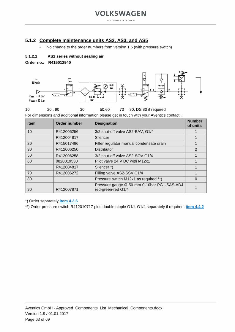
5.1.2.1 AS2 series without sealing air
Order no.: R415012940
10 20 , 90 30 50,60 70 30, DS 80 if required
For dimensions and additional information please get in touch with your Aventics contact..
Item Order number Designation Number of units
10 R412006256 3/2 shut-off valve AS2-BAV, G1/4 1
R412004817 Silencer 1
20 R415017496 Filter regulator manual condensate drain 1
30 R412006250 Distributor 2
50 R412006258 3/2 shut-off valve AS2-SOV G1/4 1
60 0820019530 Pilot valve 24 V DC with M12x1 1
R412004817 Silencer *) 1
70 R412006272 Filling valve AS2-SSV G1/4 1
80 Pressure switch M12x1 as required **) 0
90 R412007871 Pressure gauge Ø 50 mm 0-10bar PG1-SAS-ADJ red-green-red G1/4
1
*) Order separately item 4.3.6
**) Order pressure switch R412010717 plus double nipple G1/4-G1/4 separately if required, item 4.4.2

Aventics GmbH - Approved_Components_List_Mechanical_Components.docx
Version 1.9 / 01.01.2017
Page 64 of 69
5.1.2.2 AS2 series with sealing air, electrical, without timer
Order no.: R415012941
10 20 , 90 40,60 30 50,60 70 30 , DS 80 if required
For dimensions and additional information please get in touch with your Aventics contact.
Item Order number Designation Number of units
10 R412006256 3/2 shut-off valve AS2-BAV, G1/4 1
R412004817 Silencer 1
20 R415017496 Filter regulator manual condensate drain 1
30 R412006250 Distributor AS2-DIS G1/4 2
50 R412006258 3/2 shut-off valve AS2-SOV G1/4 2
60 0820019530 Pilot valve 24 V DC with M12x1 2
R412004817 Silencer *) 1
70 R412006272 Filling valve AS2–SSV G1/4 1
R412004817 Silencer 1
80 Pressure switch M12x1 as required **) 0
90 R412007871 Pressure gauge Ø 50 mm 0-10bar PG1-SAS-ADJ red-green-red G1/4 1
*) Order separately item 4.3.6
**) Order pressure switch R412010717 plus double nipple G1/4-G1/4 separately if required, item 4.4.2
Plus sealing air devices: order separately as individual components or as a unit at item 4.3.5
Aventics GmbH - Approved_Components_List_Mechanical_Components.docx
Version 1.9 / 01.01.2017
Page 65 of 69
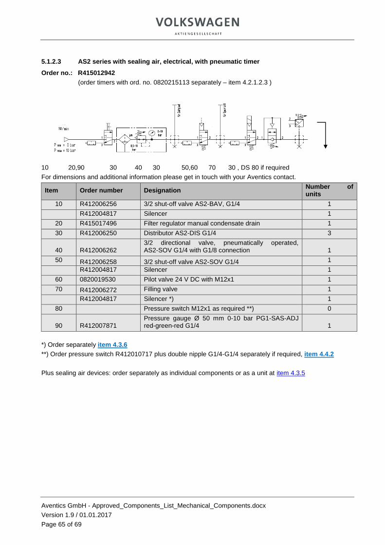
5.1.2.3 AS2 series with sealing air, electrical, with pneumatic timer
Order no.: R415012942
(order timers with ord. no. 0820215113 separately – item 4.2.1.2.3 )
10 20,90 30 40 30 50,60 70 30 , DS 80 if required
For dimensions and additional information please get in touch with your Aventics contact.
Item Order number Designation Number of units
10 R412006256 3/2 shut-off valve AS2-BAV, G1/4 1
R412004817 Silencer 1
20 R415017496 Filter regulator manual condensate drain 1
30 R412006250 Distributor AS2-DIS G1/4 3
40 R412006262 3/2 directional valve, pneumatically operated, AS2-SOV G1/4 with G1/8 connection 1
50 R412006258 3/2 shut-off valve AS2-SOV G1/4 1
R412004817 Silencer 1
60 0820019530 Pilot valve 24 V DC with M12x1 1
70 R412006272 Filling valve 1
R412004817 Silencer *) 1
80 Pressure switch M12x1 as required **) 0
90 R412007871 Pressure gauge Ø 50 mm 0-10 bar PG1-SAS-ADJ red-green-red G1/4 1
*) Order separately item 4.3.6
**) Order pressure switch R412010717 plus double nipple G1/4-G1/4 separately if required, item 4.4.2
Plus sealing air devices: order separately as individual components or as a unit at item 4.3.5

Aventics GmbH - Approved_Components_List_Mechanical_Components.docx
Version 1.9 / 01.01.2017
Page 66 of 69
5.1.2.4 AS3 series without sealing air
Order no.: R415012943
10 20 , 90 30 50,60 70 30, DS 80 if required
For dimensions and additional information please get in touch with your Aventics contact..
Item Order number Designation Number of
units
10 R412007261 3/2 shut-off valve AS3-BAV, G1/4 1
Silencer G1/2 *) 1
20 R415017497 Filter regulator manual condensate drain 1
30 R412007251 Distributor AS3-DIS G1/2 2
50 R412007259 3/2 shut-off valve AS3-SOV G1/2 1
Silencer G1/2 *) 1
60 0820019530 Pilot valve 24 V DC with M12x1 1
70 R412007273 Filling valve AS3-SSV G1/2 1
80 Pressure switch M12x1 as required **) 0
90 R412007871 Pressure gauge Ø 50 mm 0-10 bar PG1-SAS-ADJ red-green-red G1/4 1
*) Order separately item 4.3.6
**) Order pressure switch R412010717 plus double nipple G1/4-G1/4 separately if required, item 4.4.2
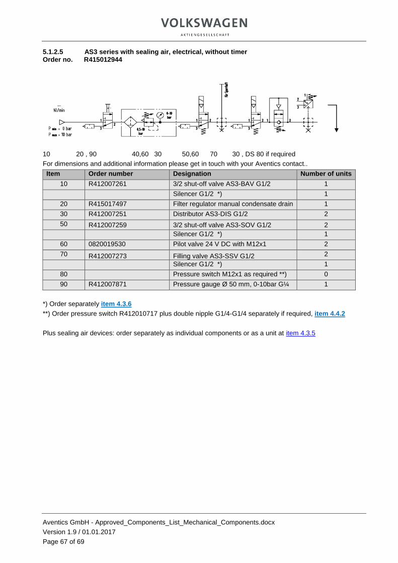
Aventics GmbH - Approved_Components_List_Mechanical_Components.docx
Version 1.9 / 01.01.2017
Page 67 of 69
5.1.2.5 AS3 series with sealing air, electrical, without timer Order no. R415012944
10 20 , 90 40,60 30 50,60 70 30 , DS 80 if required
For dimensions and additional information please get in touch with your Aventics contact..
Item Order number Designation Number of units
10 R412007261 3/2 shut-off valve AS3-BAV G1/2 1
Silencer G1/2 *) 1
20 R415017497 Filter regulator manual condensate drain 1
30 R412007251 Distributor AS3-DIS G1/2 2
50 R412007259 3/2 shut-off valve AS3-SOV G1/2 2
Silencer G1/2 *) 1
60 0820019530 Pilot valve 24 V DC with M12x1 2
70 R412007273 Filling valve AS3-SSV G1/2 2
Silencer G1/2 *) 1
80 Pressure switch M12x1 as required **) 0
90 R412007871 Pressure gauge Ø 50 mm, 0-10bar G¼ 1
*) Order separately item 4.3.6
**) Order pressure switch R412010717 plus double nipple G1/4-G1/4 separately if required, item 4.4.2
Plus sealing air devices: order separately as individual components or as a unit at item 4.3.5

Aventics GmbH - Approved_Components_List_Mechanical_Components.docx
Version 1.9 / 01.01.2017
Page 68 of 69
5.1.2.6 AS3 series with sealing air, electrical, with pneumatic timer
Order no.: R415012945
(order timer with ord. no. 0820215113 separately – item 4.2.1.2.3 )
10 20 , 90 30 50,60 70 30, DS 80 if required
For dimensions and additional information please get in touch with your Aventics contact..
Item Order number Designation Number of units
10 R412007261 3/2 shut-off valve AS3-BAV G 1/2 1
Silencer G1/2 *) 1
20 R415017497 Filter regulator manual condensate drain 1
30 R412007251 Distributor AS3-DIS G1/4 3
40 R412007263
3/2 directiona valve, pneumatically operated, AS3-SOV G1/4 with G 1/8 connection 1
Silencer G1/2 *) 1
50 R412007259 3/2 shut-off valve AS3-SOV G1/4 1
Silencer G1/2 *) 1
60 0820019530 Pilot valve 24 V DC with M12x1 1
70 R412007273 Filling valve AS3-SSV G1/2 1
80 Pressure switch M12x1 as required **) 0
90 R412007871 Pressure gauge Ø 50 mm 0-10 bar PG1-SAS-ADJ red-green-red G1/4 1
*) Order separately item 4.3.6
**) Order pressure switch R412010717 plus double nipple G1/4-G1/4 separately if required, item 4.4.2
Plus sealing air devices: order separately as individual components or as a unit at item 4.3.5
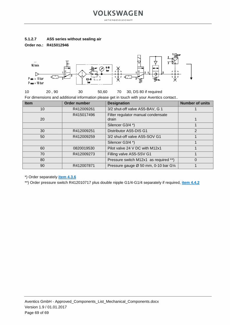
Aventics GmbH - Approved_Components_List_Mechanical_Components.docx
Version 1.9 / 01.01.2017
Page 69 of 69
5.1.2.7 AS5 series without sealing air
Order no.: R415012946
10 20 , 90 30 50,60 70 30, DS 80 if required
For dimensions and additional information please get in touch with your Aventics contact..
Item Order number Designation Number of units
10 R412009261 3/2 shut-off valve AS5-BAV, G 1 1
20 R415017496 Filter regulator manual condensate
drain 1
Silencer G3/4 *) 1
30 R412009251 Distributor AS5-DIS G1 2
50 R412009259 3/2 shut-off valve AS5-SOV G1 1
Silencer G3/4 *) 1
60 0820019530 Pilot valve 24 V DC with M12x1 1
70 R412009273 Filling valve AS5-SSV G1 1
80 Pressure switch M12x1 as required **) 0
90 R412007871 Pressure gauge Ø 50 mm, 0-10 bar G¼ 1
*) Order separately item 4.3.6
**) Order pressure switch R412010717 plus double nipple G1/4-G1/4 separately if required, item 4.4.2

Aventics GmbH - Approved_Components_List_Mechanical_Components.docx
Version 1.9 / 01.01.2017
Page 70 of 69
5.1.2.8 AS5 series with sealing air, electrical, without timer
Order no.: R415012947
10 20 , 90 40,60 30 50,60 70 30 , DS 80 if required
For dimensions and additional information please get in touch with your Aventics contact..
Item Order number Designation Number of units
10 R412009261 3/2 shut-off valve AS5-BAV, G1 1
Silencer G3/4 *) 1
20 R415017498 Filter regulator manual condensate drain 1
30 R412009251 Distributor AS5-DIS G1 2
50 R412009259 3/2 shut-off valve AS5-SOV G1 2
Silencer G1/2 *) 1
60 0820019530 Pilot valve 24 V DC with M12x1 2
70 R412009273 Filling valve AS5-SSV G1 1
Silencer G3/4 *) 1
80 Pressure switch M12x1 as required **) 0
90 R412007871 Pressure gauge Ø 50 mm, 0-10 bar PG1-SAS G1/4 1
*) Order separately item 4.3.6
**) Order pressure switch R412010717 plus double nipple G1/4-G1/4 separately if required, item 4.4.2
Plus sealing air devices: order separately as individual components or as a unit at item 4.3.5

Aventics GmbH - Approved_Components_List_Mechanical_Components.docx
Version 1.9 / 01.01.2017
Page 71 of 69
5.1.2.9 AS5 series with sealing air, electrical, with pneumatic timer
Order no.: R415012948
(order timer with ord. no. 0820215113 separately – item 4.2.1.2.3 )
10 20 , 90 30 50,60 70 30, DS 80 if required
For dimensions and additional information please get in touch with your Aventics contact..
Item Order number Designation Number of units
10 R412009261 3/2 shut-off valve AS5-BAV, G1 1
Silencer G3/4 *) 1
20 R415017498 Filter regulator manual condensate drain 1
30 R412009251 Distributor AS5-DIS G1 3
40 R412009263
3/2 directiona valve pneumatic operation AS2-SOV G1 with G1/8 connection 1
Silencer G3/4 *) 1
50 R412009259 3/2 shut-off valve AS5-SOV G1 1
Silencer G1/4 1
60 0820019530 Pilot valve 24 V DC with M12x1 1
70 R412009273 Filling valve AS5-SSV G1 1
Silencer G3/4 *) 1
80 Pressure switch M12x1 as required **) 0
90 R412007871 Pressure gauge Ø 50 mm 0-10 bar PG1-SAS-ADJ red-green-red G1/4 1
*) Order separately item 4.3.6
**) Order pressure switch R412010717 plus double nipple G1/4-G1/4 separately if required, item 4.4.2
Plus sealing air devices: order separately as individual components or as a unit at item 4.3.5