application of superpower 2g hts wire to various coil ...iss+superpower+sa-21... · to various coil...
TRANSCRIPT

superior performance. powerful technology.
SuperPower Inc. is a subsidiary of Furukawa Electric Co. Ltd.
Application of SuperPower 2G HTS Wire to Various Coil Applications
Drew W. HazeltonPrincipal Engineer, HTS Applications
ISS2012 – Tokyo, Japan – Dec. 4, 2012

ISS2012 – Tokyo, Japan – December 4, 2012SA-21 2
From GE to Furukawa
• History– 1971: Superconductivity group spins out of
General Electric and forms Intermagnetics General Corporation
– 1987: following the 1986 discovery by Bednorz and Mueller, Intermagnetics forms a dedicated group to work on HTS
– 2000: Intermagnetics forms SuperPower to develop 2G HTS technology for Energy Technology applications
– 2006: Intermagnetics is acquired by Royal Philips Electronics for MRI magnet business
• Holds SuperPower to build value– 2012: SuperPower is acquired by Furukawa
Electric Co., Ltd.

ISS2012 – Tokyo, Japan – December 4, 2012SA-21
• Automated processes• Reel-to-reel systems• High throughput, fast processes
SuperPower® 2G HTS wire: Thin film deposition on robust, flexible substrate
3
• Modular and scaleable systems• Quality assurance throughout• Rigorous testing, product
certification with each delivery

ISS2012 – Tokyo, Japan – December 4, 2012SA-21
Each layer serves a function….• Substrate (Hastelloy® C-276) provides mechanical strength,
electropolished base for subsequent layer growth• Buffer stack provides:
– Diffusion barrier between substrate and superconductor– IBAD MgO layer provides texture template for growing aligned
superconductor, necessary for high current density– Final buffer layer provides lattice match between buffer stack and
superconductor• HTS superconductor layer – (RE)BCO superconductor with BZO based
pinning sites for high current carrying capability in background magnetic field.
• Ag layer – provides good current transfer to HTS layer while providing ready path oxygen diffusion during final anneal.
• Cu layer – provides stabilization(parallel path) during operation and quench conditions.
4

ISS2012 – Tokyo, Japan – December 4, 2012SA-21
2G HTS Wire Specifications
5
• Robust, high-performance wire; several architectures, incl. variations of width, substrate thickness, stabilizer, and insulation
– Insulated wire: Kapton wrapped - 30% overlap or butt-wrap available
• Two chemical formulations:– AP (Advanced Pinning) – for enhanced in-field performance in
motors, generators, transformers, SMES, high field magnets, etc.
– CF (Cable Formulation) – for cable or FCL

ISS2012 – Tokyo, Japan – December 4, 2012SA-21
0
200
400
600
800
1000
1200
0.000 0.002 0.004 0.006 0.008 0.010 0.012
stress (M
Pa)
strain
Copper thickness
40 µm
60 µm
100 µm
4 K and 77 K data from NHMFL
SuperPower 2G HTS wire has high tensile strength

ISS2012 – Tokyo, Japan – December 4, 2012SA-21
2G HTS offers excellent performance for all electrical device operating ranges
7
Normalized Ic vs. Applied Field //c
0.01
0.10
1.00
10.00
0.0 2.0 4.0 6.0 8.0 10.0 12.0 14.0 16.0Applied Field B (T)
Ic (B
//c, T
) / Ic
(sel
f fie
ld, 7
7 K
)
4.2 K 14 K 22 K 33 K 45 K 50 K 65 K 77 K
Cables, FCLs, transformers
Motors, generators
SMES

ISS2012 – Tokyo, Japan – December 4, 2012SA-21
Critical current vs. temperature and magnetic field of recent AP production material
8

ISS2012 – Tokyo, Japan – December 4, 2012SA-21
Advanced pinning continues to progress
9
5 nm sized, few hundred nanometer long BZO nanocolumns with ~ 35 nm spacing created during in situ MOCVD process with 7.5% Zr
Microstructure of production MOCVD HTS wires with standard 7.5% Zr doping
ISS2012 – Tokyo, Japan – December 4, 2012SA-21
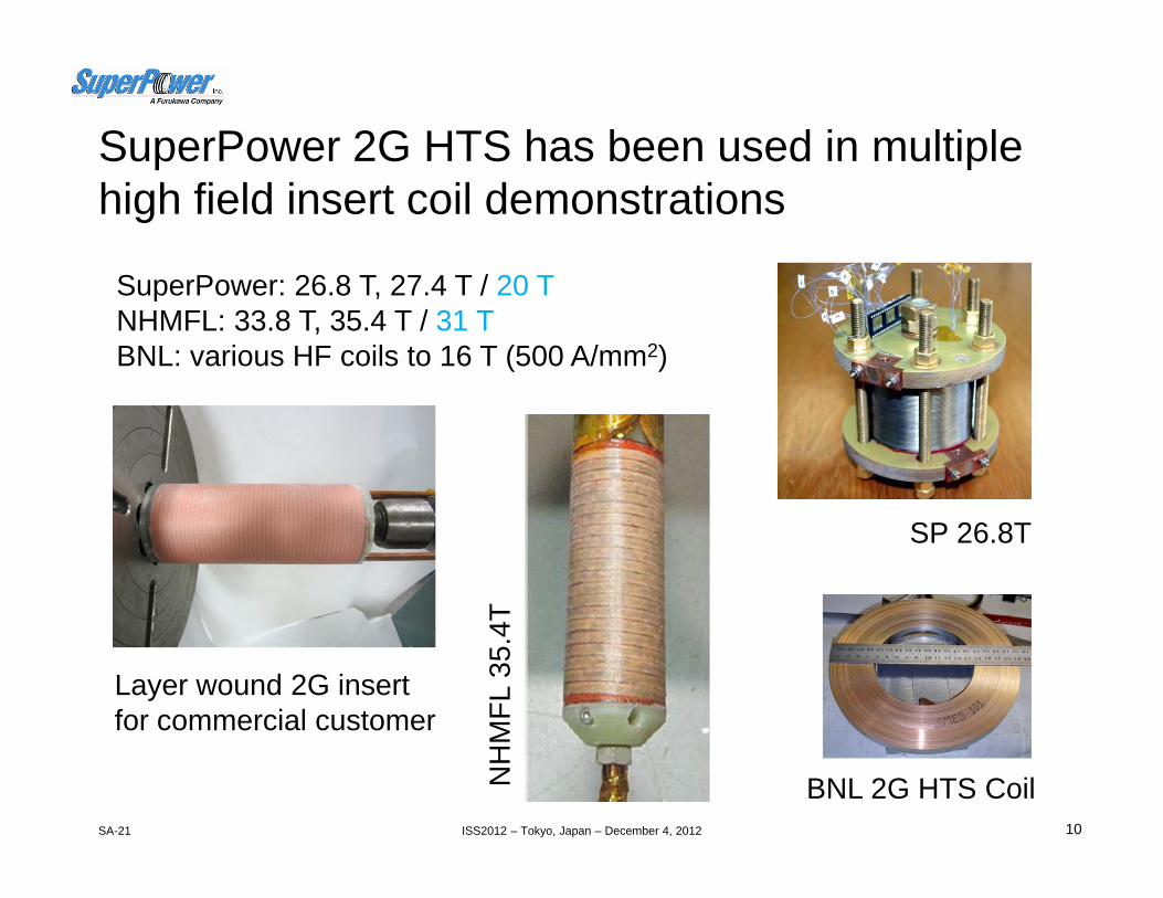
SuperPower 2G HTS has been used in multiple high field insert coil demonstrations
10
SuperPower: 26.8 T, 27.4 T / 20 TNHMFL: 33.8 T, 35.4 T / 31 TBNL: various HF coils to 16 T (500 A/mm2)
SP 26.8T
BNL 2G HTS CoilNH
MFL
35.
4T
Layer wound 2G insert for commercial customer

ISS2012 – Tokyo, Japan – December 4, 2012SA-21 11
DOE Smart Grid SFCL transformer demonstration
• Funding: DOE Smart Grid Demo $10.7M (Total Program = $21.5M)
• Partners:– SuperPower (project lead)– SPX I Waukesha Electric– University of Houston– Southern California Edison
• Project objective:– Design, develop, manufacture and test
SmartGrid-compatible SFCL Transformer• 28 MVA 3-phase FCL Medium Power Utility
Transformer (69 kV / 12.47 kV class) • Testing on So. California Edison Smart
Grid site in Irvine, CA – plan min 1 year of grid operation
– First transformer to use significant amounts of 2G HTS wire (14km/12mm)
• Relevance:– Smaller footprint than conventional
transformers, enabling existing substations to increase distribution capability without expanding into limited or expensive real estate
• Benefits– Greater efficiency– Smaller, lighter, potentially quieter– Safety: no oil for cooling– Can run indefinitely above rated power
without affecting device life• Add FCL feature …
– Compatibility with Smart Grid requirements• Incorporation of FCL feature to
rapidly detect and limit surges at high power levels that can be handled by downstream equipment
– 30-50% reduction of prospective fault current
– Low ac loss conductor development at UH
ISS2012 – Tokyo, Japan – December 4, 2012SA-21
SuperPower focus on conductor design and manufacture• 2G HTS conductor for the FCL transformer must meet all of the following
requirements: • Fault current limiting function
– Conductor structure requires ~ 25 mΩ/m resistance at 70K to provide sufficient resistive impedance during fault
– Conductor must have sufficient mass to limit temperature rise during fault• Mechanical strength
– Conductor structure must withstand application of insulation– Conductor stack must with stand fault current forces (axial compression)
along long width of tape without buckling

ISS2012 – Tokyo, Japan – December 4, 2012SA-21 13
• Funding: DOE ARPA-E $4.2 million (Total program = $5.25 million)
• Project timeline: 2011-2013• Partners:
– ABB, Inc.: project lead, power electronics– Brookhaven National Lab: SMES coil – SuperPower Inc.: 2G HTS wire, coil
development – University of Houston, TcSUH:
manufacturing improvements for wire cost reductions
• Objective: proof-of-concept of modular, scalable SMES system by integrating an advanced power conversion concept with superconducting magnet coil
– 20 kW UHF SMES device with 2.5 MJ class capacity
– Field over 20 T at 4.2K– 2G HTS wire with high critical currents
(~ 800 A) to drive down price/performance– Capable of flexible connection to medium
voltage distribution networks at 15-36 kV• Relevance:
– High power and high energy storage in a compact device with cost advantages in material and system
– Modular units for both long (hours) and short term (seconds) storage requirements to help load leveling on the grid being fed by variable renewable sources
ARPA-E SMES development
BNL built 2G HTS Coil - One of 30 fabricated and tested to date

ISS2012 – Tokyo, Japan – December 4, 2012SA-21
Army Research Lab – SMES for Micro-Grid
14
• Funding: US Army Research Laboratory $4.2 M of $7M funded to date
• Project timeline: 3 yrs., 2012 - 2015• Partners:
– SuperPower Inc: project lead, 2G HTS wire, coil development
– Brookhaven National Lab: SMES coil – MTech Labs: power electronics– University of Houston, TcSUH: low ac
loss material development
• Objective: Build upon the developments achieved in the ARPA E-SMES project with HTS superconductors and adapt those developments to the Army’s tactical Microgrid application (lower voltage).
– Model, design and fabricate a 2.5MJ class tactical Microgrid SMES
– Modify 2G HTS MJ ARPA E-SMES coil to meet the tactical Microgrid requirements
– Develop robust quench protection and switching components
– Investigate methods to reduce ac losses through superconductor tape design
• Relevance: – High power and high energy storage in a
compact device enables a power solution for remote areas.
– Build on ARPA E investment in SMES technology to provide a practical application in real world environments.

ISS2012 – Tokyo, Japan – December 4, 2012SA-21 15
ARPA-E REACT (Rare earth alternatives for critical technologies) Program
Low-cost superconducting wire for future wind turbine generatorsPartners:University of Houston – project lead, wire improvementsSuperPower – wire manufactureNREL (National Renewable Energy Laboratory) – impact evaluation of enhanced
superconducting wire on overall system performanceTai Yang Research Company – coil fabrication and testTECO Westinghouse Motor Company – development of device design
Budget: $3.1 millionProgram Period: 3 years
Status: project underway - work began January 2012

ISS2012 – Tokyo, Japan – December 4, 2012SA-21
Significant improvement in lift factor at targeted operating conditions demonstrated
16

ISS2012 – Tokyo, Japan – December 4, 2012SA-21
Summary
17
• SuperPower 2G HTS conductors provide high current density and high strength options for a variety of applications
• High critical currents available – 100A standard; 110-120+ A premium (4 mm width)
• Uniform critical current over long lengths: +/- 10% standard deviation• Single piece lengths of 50-300 m (without splices); up to 1 km and
longer with high quality splices• Excellent joints & solderability• Manufacturing volume steadily increasing

ISS2012 – Tokyo, Japan – December 4, 2012SA-21
Thank you for your attention.
For more information, please visitwww.superpower-inc.com
18