application of storage devices to improve dynamic
TRANSCRIPT

International Journal of Electrical Engineering. ISSN 0974-2158 Volume 6, Number 5 (2013), pp.493-508 © International Research PublicationHouse http://www.irphouse.com
Application of Storage Devices to Improve Dynamic Performance of FLC Based Power System
*SandeepDhundhara, **Anil Kumar and ***J.Raja
*M.Tech (Power System), Final Year, Department of EE, DCRUST, Murthal, Sonepat, India.e-mail; [email protected].
**Assistant Professor Department of EE, DCRUST, Murthal, Sonepat, Haryana, India.e- mail: [email protected]
***Assistant Director, National Power Training Institute, Ministry of Power, Govt. of Inida, Sector-33, Near NHPC, Faridabad, Haryana, India.
e-mail: [email protected].
Abstract
This paper present a comparative transient performance of different types of single machine power system connected to infinite bus with the presence of energy storage devices like Superconducting Magnetic Energy Storage (SMES) and Capacitive Energy Storage (CES). For Automatic Generation Control (AGC) loop thermal unit is considered. The thermal unit is either single or double reheat turbine. PI controller is provided for AGC loop, PI, CPSS and Fuzzy Logic Power System Stabilizer (FPSS) is used for power system AVR loop with SMES and CES unit. The transient performances are carried out with ±25% load variations. Finally the transient performance shows power system with PI based AGC loop and FLC based AVR loop with CES unit gives better control performance than others system with PI based AGC loop and FLC based AVR loop with SMES unit in terms of settling time and damping effect. Keywords: Automatic Generation Control (AGC), Automatic Voltage Regulator (AVR), Capacitive Energy Storage (CES), Superconducting Magnetic Energy Storage (SMES). INTRODUCTION In any power system, oscillations may arise due to line Faults, bus bar faults or load changes.so it is desirable feature to achieve better frequency constancy. However, both active and reactive power demands are never steady and they continually change with the rising or falling trend. The Steam input to turbo-generators (or water input to

494 SandeepDhundhara et al
hydro-generator) must, therefore, be continuously regulated to match the active power demand, failing which the machine speed will vary with consequent change in frequency which may be highly undesirable. Also the excitation of generators must be continuously regulated to match the reactive power demand with reactive generation, otherwise the voltages at various system buses may go beyond the prescribed limits. In modern large interconnected systems, manual regulation is not feasible and therefore automatic generation and voltage regulation equipment is installed on each generator. To ensure the quality of the power supply, we need to design a load frequency management system that deals with the management loading of the generator with the frequency. There has been continuing interest in designing strategy for load frequency controls has been proposed since 1970 reference [1] - [3] and [27]. In reference [4] have studied the AGC of a hydro-thermal system considering non-reheat type thermal system neglecting Generation Rate Constraints (GRC). In reference [5] have investigated the AGC problem of a Hydro-Thermal system provided with integral type supplementary controllers. The model uses continuous mode strategy, where both system and controllers are assumed to work in the continuous mode. It is to be appreciated that in a realistic situation, the system works in the continuous mode whereas the controllers work in the discrete mode. Perhaps in reference [6] are the first to present comprehensive analysis of AGC of an interconnected hydrothermal system in continuous- discrete mode with classical controllers. In the interconnected Hydro-Thermal system used by them, the thermal system uses reheat turbine. and the hydro system uses a mechanical governor. Generator excitation controls have been installed and made faster to improve stability. Power system stabilizers have been added to the excitation systems to improve oscillatory instability, it is used to provide a supplementary signal to the excitation system. The basic function of the power system stabilizer is to extend the stability limit by modulating generator excitation to provide positive damping torque to power swing modes. In reference [7] have described a comparative transient performance of single-input conventional power system stabilizer (CPSS) and dual-input power system stabilizer (PSS), namely PSS4B.Reference [8] have proposed the PID based power system stabilizer and reference [9] have proposed the self-tuning PID power system stabilizer for a multi machine power system. A typical power system stabilizer consists of a phase compensation stage, a signal washout stage and a gain block. To provide damping, a PSS must provide a component of electrical torque on the rotor in phase with the speed deviations. Power system stabilizer input signals includes generator speed, frequency and power. For any input signal, the transfer function of the PSS must compensate for the gain and phase characteristics of the excitation system, the generator and the power system. These collectively determine the transfer function from the stabilizer output to the component of electrical torque which can be modulated via excitation control. The PSS, while damping the rotor oscillations, can cause instability of the turbine generator shaft torsional modes. Selection of shaft speed pick-up location and torsional notch filters are used to attenuate the torsional mode frequency signals. The PSS gain and torsional filter however, adversely affects the exciter mode damping

Application of Storage Devices to Improve Dynamic Performance 495
ratio. The use of accelerating power as input signal for the PSS attenuates the shaft torsional modes inherently, and mitigates the requirements of the filtering in the main stabilizing path. One of the solutions to increase system damping is the use of an electrical storage unit such as Battery Energy Storage Systems (BESS), Compressed Air Energy Storage (CAES), Flywheel Energy Storage (FES), Superconducting Magnetic Energy Storage (SMES), and Capacitive Energy Storage (CES).As compared to other devices the efficiency of SMES and CES is better in reference [10]. Although superconductivity was discovered in 1911, SMES has been under study for electric utility energy storage application since the early 1970s .Since the successful commissioning test of the BPA 30-MJ unit in reference [11], SMES systems have received much attention in power system applications, such as, diurnal load demand leveling, frequency control, automatic generation control, uninterruptible power supplies, etc. The real power can be absorbed or released from the low loss superconducting magnetic inductor according to system power requirements. The use of SMES and battery energy storage for load levelling application and for improvement of the dynamic performance of power system have been described [10], [11]. The importance of control system using SMES has been presented as one of the powerful stabilizers for undamped oscillations which tends to occur in a long distance bulk power transmission system has been viewed and analysed in the literature [12] - [14]. In reference [15], the improvement in AGC with the addition of a small capacity SMES unit is studied, and time domain simulations are used to study the performance of the power system dynamics are analyzed. Their applications in real power have invited problems form the viewpoints of operation, maintenance, cost but the only advantages of SMES is very much useful for high power applications. But SMES is an expensive device. However, capacitive energy storage (CES) may be a better alternative choice to damp out the power frequency oscillation, following any perturbation in power system. A small rating capacitive energy storage (CES) can effectively damp out the power frequency and tie line power oscillations caused by small perturbations to the load. The use of superconducting magnetic energy storage (SMES) units for LFC application has been suggested in reference [16]. The losses in CES units would be considerably less when compared with SMES units of same storage capacity. The CES units are practically maintenance free. Furthermore, they do not impose any environmental problem, unlike magnetic energy storage units in reference [17]. The operation is quite simple and less expensive compared with SMES which requires a continuously operating liquid helium system. In CES systems there is no need to ensure a continuous flow of current, as required in magnetic storage systems .By suitable control of CES unit to the system significantly improves this situation and the oscillations are practically damped out. A few investigations have been carried out using Fuzzy Logic Controllers (FLC) for AGC of thermal Systems in references [18]-[20]. Fuzzy logic is a powerful problem-solving methodology with a myriad of applications in embedded control and information processing. Fuzzy logic resembles human decision making with its ability to work from approximate data and find precise solutions. The control method of

496 SandeepDhundhara et al
modelling human language has many advantages, such as simple calculation, high robustness, lack of a need to find the transfer function of the system, suitability for nonlinear systems, etc. Therefore, considering these views Fuzzy Logic Controllers have been used in AVR. Attempt has been made to examine suitable number of triangular membership functions (MFs) that can provide better dynamic response. A fuzzy logic controller converts a set of linguistic rules based on expert knowledge to automatic control strategy. Thus fuzzy logic should be superior to the conventional controller. Hence for all practical purpose we can say that the Fuzzy controllers are quite robust. In the interconnected hydro-thermal system, the thermal system uses reheat turbine and the hydro system uses a mechanical governor. In modern hydro thermal system, reheat type turbine and electric governor in reference [6] are used.. Reheating in reheat turbine may be carried out in single or double stage. In reference [21], transfer function model for single stage turbine is given. System Investigation A single machine connected to infinite bus system (SMIB) is considered reference [23]. The MATLAB-SIMULINK representation of CPSS subsystem in Fig. 1, AGC subsystem in Fig. 3, SMIB system with AVR, exciter, Synchronous generator, CPSS loop, AGC loop and subsystem loop is shown in Fig. 2, subsystem SMES is shown in Fig. 4 and subsystem CES is shown in Fig. 5.The synchronous generator with AVR, IEEE STIA thyristor excitation system along with generator and equivalent transmission line reactance are represented by a two axis fourth order model.
Fig. 1.Block Diagram of CPSS
Fig. 2 Block Diagram of SMIB with AVR Synchronous Generator, CPSS Loop, AVR Loop with Energy Storage Devices

Application of Storage Devices to Improve Dynamic Performance 497
Fig 3.AGC loop Sub System
Fig. 4.Block Diagram of SMES
Fig 5.Block Diagram of CES
Single Input Conventional Power System Stabilizer The basic function of a PSS is to add damping to the generator rotor oscillations by controlling its excitation using auxiliary stabilizing signal. Reference [22] to provide
498 SandeepDhundhara et al
damping, the stabilizer must produce a component of electrical torque in phase with the rotor speed deviation. For the simplicity a conventional PSS is modeled by two stage (identical), lead/lag network which is represented by a gain Kpss and four time constants Td1 to Td4. This network is connected with a washout circuit of a time constant Tww as shown in Fig. 1. In Figure 1 the phase compensation block provides the appropriate phase lead characteristics to compensate for the phase lag between exciter input and generator electrical torque. The phase compensation may be a single first order block as shown in Figure 1 or having two or more first order blocks or second order blocks with complex roots. The signal washout block serves as high pass filter, with time constant Tw high enough to allow signals associated with oscillations in Wr to pass unchanged, which removes d.c. signals. Without it, steady changes in speed would modify the terminal voltage. It allows PSS to respond only to changes in speed. The stabilizer gain Kpss determines the amount of damping introduced by PSS. Ideally, the gain should be set at a value corresponding to maximum damping; however, it is limited by other consideration.
Super Conducting Magnetic Energy Storage An SMES unit consists of a large superconducting coil at the cryogenic temperature. This temperature is maintained by a cryostat or dewar that contains helium or nitrogen liquid vessels. The transfer function model SMES unit contained DC Superconducting coil and converter which are connected by Star-Delta/Delta-Star transformer. The converter impresses positive or negative voltage on the superconducting coil. Charge and discharge are easily controlled by simply changing the delay angle α that controls the sequential firing of the thyristors . If α is less than 90˚, the converter operates in the rectifier mode (charging). If α is greater than 90˚ , the converter operates in the inverter mode (discharging). As a result, power can be absorbed from or released to the power system according to requirement. At the steady state, SMES should not consume any real or reactive power refereed in [10]. The control of the converter firing angle provides the DC voltage Ed appearing across the inductor to be continuously varying within a certain range of positive and negative values. The inductor is initially charged to its rated value Ido by applying a small positive voltage. Once the current reaches the rated value, it is maintained constant by reducing the voltage across the inductor to zero since the coil is referred in [22] superconducting. Neglecting the transformer and the converter losses. The DC voltage is given by (1). d do d cE = 2V COSα - 2I R (1) Where, Ed = DC voltage applied to the inductor (KV), α = firing angle (degree), Id = current through the inductor (KA), Rc = equivalent commutating resistance (ohm), Vdo= maximum open circuit bridge voltage of each 6-pulse converter at α = 0 deg (KV). The inductor is first charged to its rated current, Ido by applying a little positive voltage. Once the current has attained the rated value, it is held constant by reducing voltage ideally to zero since the coil is superconducting. A very small voltage may require to overcoming the commutating resistance. The energy stored at any instant in references [25], [26],

Application of Storage Devices to Improve Dynamic Performance 499
Where, L=Inductance of SMES (H). A Capacitive Energy Storage (CES) unit consists of, from circuit point of view, a super-capacitor or a cryogenic hyper-capacitor (CHC), a power conversion system (PCS) which includes a inverter/rectifier. The storage capacitor may consist of many discrete capacitors connected in parallel, having lumped capacitance C .The capacitor can be charged to a set value of voltage (which is less than the full charge) from the utility grid during normal operation of the grid in reference [16]. Charging in the steady state mode and the power modulation during dynamic oscillatory period is controlled by the application of the proper voltage to the capacitor so that the desired current flows into or out of the CES. This can be achieved by controlling the firing angle of the convertor bridges. The capacitor is initially charged to its normal voltage, Edo by the PCS. Once the voltage of the capacitor has reached, Edo it is kept floating at this voltage by continuing Supply from the PCS to compensate for Dielectric and other leakage losses of the capacitor. The energy stored at any instant,
2
2 d
cCEW MJ (2)
Where C = capacitance of CES (farad), Ed=Dc Voltage applied to the Capacitor. Fuzzy Logic Based Power System Stabilizer Fuzzy Logic Based Power system stabilizers (FPSSs) are designed to excitation system to show a good control performance in various operating conditions and to enhance the damping during low frequency oscillations. This paper presents a study of fuzzy logic power system stabilizer to achieve the limitation of CPSS with SMES and CES unit connected to a single machine power system. For designing FPPS, speed deviation (Δω) and acceleration (Δδ) of the rotor of synchronous generator were taken as the input to the fuzzy logic controller connected to single machine infinite bus(SMIB) system. These variables take vital effects on damping of the generator shaft mechanical oscillations. The performance of the Fuzzy Logic Based Power system stabilizers (FPSSs) is compared with the conventional power system stabilizer (CPSS) and PI controller. The simulations were tested under different operating condition. In the design of fuzzy-logic controllers, unlike most conventional methods, a mathematical model is not required to describe the system under study. It is based on the implementation of fuzzy logic technique to PSS to improve system damping. The effectiveness of the fuzzy logic PSS in a single machine infinite bus is demonstrated by the Simulink program (Matlab Software). The nonlinear model of single machine infinite bus system (SMIB) developed using Simulink. The performance of fuzzy logic PSS is compared with and without CPSS .The stabilizing signal is introduced in the
2L*IdW MJL 2
500 SandeepDhundhara et al
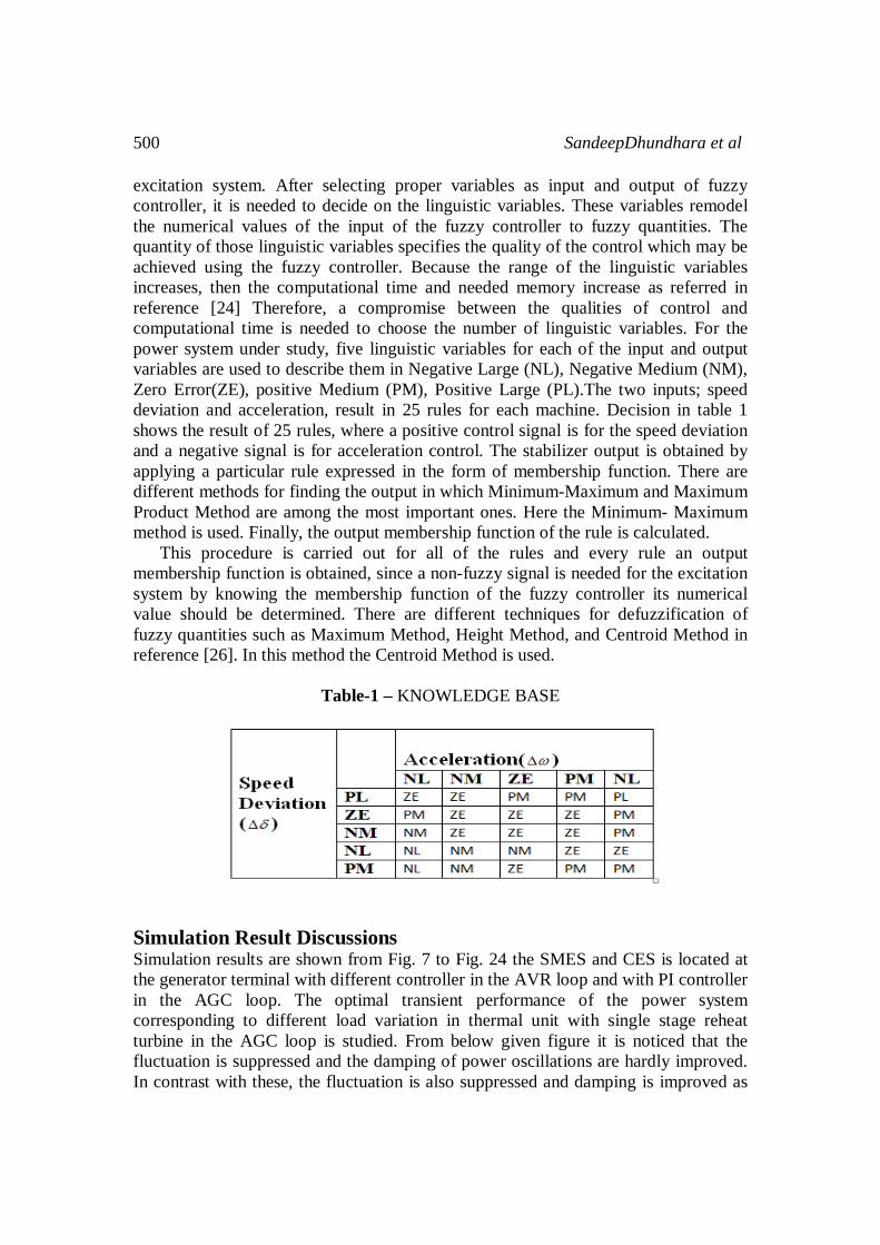
excitation system. After selecting proper variables as input and output of fuzzy controller, it is needed to decide on the linguistic variables. These variables remodel the numerical values of the input of the fuzzy controller to fuzzy quantities. The quantity of those linguistic variables specifies the quality of the control which may be achieved using the fuzzy controller. Because the range of the linguistic variables increases, then the computational time and needed memory increase as referred in reference [24] Therefore, a compromise between the qualities of control and computational time is needed to choose the number of linguistic variables. For the power system under study, five linguistic variables for each of the input and output variables are used to describe them in Negative Large (NL), Negative Medium (NM), Zero Error(ZE), positive Medium (PM), Positive Large (PL).The two inputs; speed deviation and acceleration, result in 25 rules for each machine. Decision in table 1 shows the result of 25 rules, where a positive control signal is for the speed deviation and a negative signal is for acceleration control. The stabilizer output is obtained by applying a particular rule expressed in the form of membership function. There are different methods for finding the output in which Minimum-Maximum and Maximum Product Method are among the most important ones. Here the Minimum- Maximum method is used. Finally, the output membership function of the rule is calculated. This procedure is carried out for all of the rules and every rule an output membership function is obtained, since a non-fuzzy signal is needed for the excitation system by knowing the membership function of the fuzzy controller its numerical value should be determined. There are different techniques for defuzzification of fuzzy quantities such as Maximum Method, Height Method, and Centroid Method in reference [26]. In this method the Centroid Method is used.
Table-1 – KNOWLEDGE BASE
Simulation Result Discussions Simulation results are shown from Fig. 7 to Fig. 24 the SMES and CES is located at the generator terminal with different controller in the AVR loop and with PI controller in the AGC loop. The optimal transient performance of the power system corresponding to different load variation in thermal unit with single stage reheat turbine in the AGC loop is studied. From below given figure it is noticed that the fluctuation is suppressed and the damping of power oscillations are hardly improved. In contrast with these, the fluctuation is also suppressed and damping is improved as
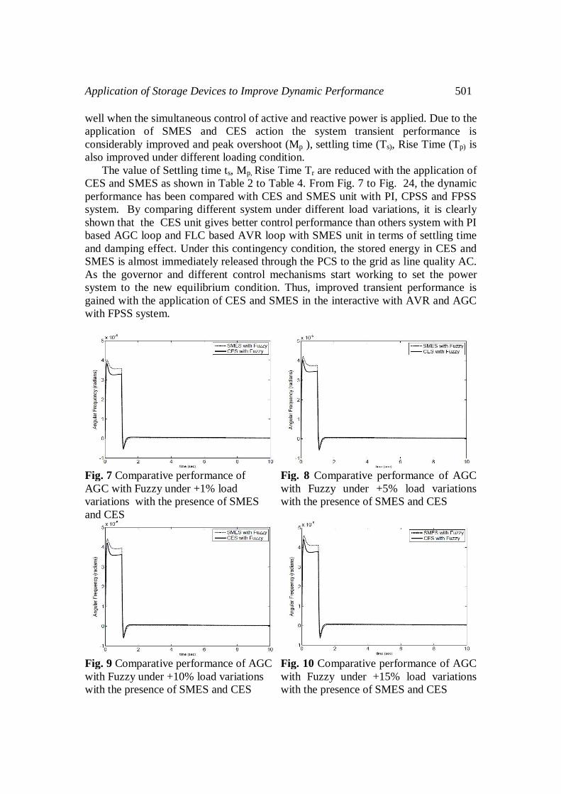
Application of Storage Devices to Improve Dynamic Performance 501
well when the simultaneous control of active and reactive power is applied. Due to the application of SMES and CES action the system transient performance is considerably improved and peak overshoot (Mp ), settling time (Ts), Rise Time (Tp) is also improved under different loading condition. The value of Settling time ts, Mp, Rise Time Tr are reduced with the application of CES and SMES as shown in Table 2 to Table 4. From Fig. 7 to Fig. 24, the dynamic performance has been compared with CES and SMES unit with PI, CPSS and FPSS system. By comparing different system under different load variations, it is clearly shown that the CES unit gives better control performance than others system with PI based AGC loop and FLC based AVR loop with SMES unit in terms of settling time and damping effect. Under this contingency condition, the stored energy in CES and SMES is almost immediately released through the PCS to the grid as line quality AC. As the governor and different control mechanisms start working to set the power system to the new equilibrium condition. Thus, improved transient performance is gained with the application of CES and SMES in the interactive with AVR and AGC with FPSS system.
Fig. 7 Comparative performance of AGC with Fuzzy under +1% load variations with the presence of SMES and CES
Fig. 8 Comparative performance of AGC with Fuzzy under +5% load variations with the presence of SMES and CES
Fig. 9 Comparative performance of AGC with Fuzzy under +10% load variations with the presence of SMES and CES
Fig. 10 Comparative performance of AGC with Fuzzy under +15% load variations with the presence of SMES and CES

502 SandeepDhundhara et al
Fig. 11 Comparative performance of AGC with Fuzzy under +25% load variations with the presence of SMES and CES
Fig. 12 Comparative performance of AGC with fuzzy under -25% load variations with the presence of SMES and CES
Fig. 13 Comparative performance of AGC with CPSS under +1% load variations with the presence of SMES and CES
Fig. 14 Comparative performance of AGC with CPSS under +5% load variations with the presence of SMES and CES
Fig. 15 Comparative performance of AGC with CPSS under +10% load variations with the presence of SMES and CES
Fig. 16 Comparative performance of AGC with CPSS under +15% load variations with the presence of SMES and CES

Application of Storage Devices to Improve Dynamic Performance 503
Fig. 17 Comparative performance of AGC with CPSS under +20% load variations with the presence of SMES and CES
Fig. 18 Comparative performance of AGC with CPSS under +25% load variations with the presence of SMES and CES
Fig. 19 Comparative performance of AGC with CPSS under +1% load variations with the presence of SMES and CES
Fig. 20 Comparative performance of AGC with CPSS under +5% load variations with the presence of SMES and CES
Fig. 21 Comparative performance of AGC with CPSS under +10% load variations with the presence of SMES and CES
Fig. 22 Comparative performance of AGC with CPSS under +15% load variations with the presence of SMES and CES

504 SandeepDhundhara et al
Fig. 23 Comparative performance of AGC with CPSS under +20% load variations with the presence of SMES and CES
Fig. 24 Comparative performance of AGC with CPSS under +25% load variations with the presence of SMES and CES
Table 2.Performance Single Machine Power System with PI under the influence of SMES and CES for different load variations
Table 3.Performance Single Machine Power System with CPSS under the influence of SMES and CES for different load variations

Application of Storage Devices to Improve Dynamic Performance 505
Table 4.Performance Single Machine Power System with CPSS under the influence of SMES and FPSS for different load variations.
Conclusion This paper concludes that Inclusion of CES and SMES unit in the coordinated AVR with PI, CPSS,FPSS and PI controller in AGC loop with either single stage or double stage reheat turbine improves the transient performance considerably. In this work initially the effectiveness of power system stabilizer in damping power system oscillation is reviewed. FPSS with CES unit shows the better control performance than FPSS with SMES unit in terms of settling time (Ts), Peak overshoot (Mp) and damping effect as compared with CPSS with SMES and CES unit and PI with SMES and CES unit. Therefore, it can be concluded that the performance of FPSS with CES unit is better than FPSS with SMES unit. Hence Capacitive Energy Storage Unit and Superconducting magnetic energy storage units with FPSS are successfully practically implemented for improving small signal dynamic performance of the power system. Appendix AGC loop data : R=2.4Hz/per unit MW, b=0.275, Single stage-reheat turbine data: Tg=0.08s,Tt=0.3s, c=0.35, Tr=4.2s, Double stage-reheat turbine data:Tr1=10s, Tr2=10s, Tt=0.3s, alpha=Kr1=0.2,beta=Kr2=0.2, SMIB data:Xd=0.973, Xd’=0.19, D=0.0, Xq=0.55, Tdo’=7.765s, H=4.63,Re=0.003,Xe=0.99, AVR loop data: Ka=50,Ta=0.05s, CPSS data :Tww=10s ,Td2=0.05s , Td4=0.05s, SMES data:Tdc =0.03 s, Kf=35 KV/unit MW, Kid = 0.20 KV/KA ,Iido = 4.5 KA, L = 2.42H, CES data: C=1 F, R=100 Ohm, tdc=0.05s ,kvd=0.1kA/kV ,kace=40 kA/unit MWed0=20v.

506 SandeepDhundhara et al
References
[1] ANSI/IEEE std 122-1985, “IEEE recommended practice for functional and performance characteristics of control system for steam turbine generator units”, The institute of EEE USA, 1985.
[2] P. Kundur, “ Power System Stability and Control ”, McGraw-Hill Inc, 1994. [3] P.M. Anderson and A.A. Faurd, “ Power System Control & Stability ”, IEEE,
Press, Revised printing, 1994, pp. 310-368 [4] C. Concordia and L.K. Kirchmayer, “ Tie-Line Power and Frequency Control
of Electric Power System - Part It ”, AIEE Transaction, vol. 73, Part- 111-A, pp. 133-146, April 1954,
[5] M.L. Kothari, B.L. Kaul and J. Nanda, “ Automatic Generation Control of Hydro-Thermal system ”, journal of Institute of Engineers (India),vo1.6.1,pp. 85-9.
[6] J. Nanda, M.L. Kothari, P.S. Satsangi, “ Automatic Generation Control of an Interconnected hydrothermal system in Continuous and Discrete modes considering GRC ”, IEE Proc., vol. 130, pt D, No.1, pp. 455-460, Jan. 1983.
[7] A. Chatterjee, S. Ghoshal, and V. Mukherjee, “ A comparative study of single input and dual input power system stabilizer by hybrid evolutionary programming”, in Nature Biologically Inspired Computing,2009. NaBIC 2009. World Congress on, pp. 1047-1052, Dec. 2009.
[8] G. Radman and Y. Smaili, “ Performance evaluation of pid power system stabilizer for synchronous generator”, in Southeastcon '88., IEEE Conference Proceedings, April , pp. 597-601,1988.
[9] W. Chi - Jui and H. Yuan - Yih, “ Design of self-tuning PID power system stabilizer for multi-Machine Power Systems ”, Power Systems, IEEE Transactions on Sustainable Energy, vol. 3, no. 3, pp. 1059 - 1064, Aug 1988.
[10] Mohd. Hasan Ali, Bin Wu,and Roger A. Dougal, “ An Overview of SMES Applications in Power and Energy Systems” IEEE Transactions on Sustainable Energy, Vol. 1, No. 1, pp. 38-44, April 2010.
[11] H. J. Boenig and J. F. Hauer, “ Commissioning tests of the Bonneville power administration 30 MJ superconducting magnetic energy storage unit,” IEEE Trans. Power App. Syst., vol. PAS-104, no. 2, pp. 302–309, Feb. 1985.
[12] Y. Mitani, K. Tsuji, Y. Murakami, “Application of Superconducting Magnetic Energy storage to improve power system dynamic performance ”, IEEE Transaction on power system, Vol 3, No.4, p.1418-1425,1988.
[13] Rogers, J.D., Boenig, H.J., Bronson, J.C., Colyer, D.B., Hassenzahl, W.V., Turner, R.D., and Schermer, R.I.: “ 30 MJ superconducting magnetic energy storage (SMES) unit for stabilizing an electric transmission system”, IEEE Trans., pp 367-371, 1979.
[14] H.A. Peterterson, N. Mohan and R.W. Boom, “ Super Conductive energy storage Inductor-Converter Units for power system”, IEE Trans. On Power Apparatus and Systems, Vol. PAS-94,No.4,PP 1337-1348, July/August 1975
[15] S.C. Tripathy, R.Balasubramaniam, P.S. Chandramohan Nair,” Effect of Superconducting Magnetic Energy Storage on Automatic Generation Control
Application of Storage Devices to Improve Dynamic Performance 507
Considering Governer Dead band and Boiler dynamics. ”IEEE tran. On power system Vol 7, pp. 1266-1273, Aug 1992.
[16] S.C. Tripathy, R. Balasubramanian,P.S. Chandramohan Nair , “ Small rating capacitive energy storage for dynamic performance improvement of automatic generation control ”, IEE proceedings, Vol 138, pp 103 – 111,Jan 1991.
[17] Rajesh Joseph Abraham, D. Das and AmitPatra “Automatic Generation Control of an Interconnected Power System with Capacitive Energy Storage” International Journal of Electrical and Electronics Engineering, pp 351-354, 4:5 2010
[18] A. Demiroren , E. Yesil, “ Automatic Generation control with FUZZY logic controller in power system including SMES unit ”, Department of Electrical Engineering, Electrical and Electronic Engineering faculty, pp 38-47,2004. Elsevier ltd.
[19] C.S. Chang, Weihui Fu, “Area Load frequency control using FUZZY gain scheduling of PI controller ”, Department of Electrical Engineering, National University of Singapore,1977 Elsevier science S.A.
[20] N. Nallathambi, P.N. Neelakanten, “ Fuzzy logic based power system stabilizer”, IEEE Transaction, pp. 356-361, 2004.
[21] Janardan Nanda, AshishMangla and Sanjay Sui, “ Some New Findings on Automatic Generation Control of an Interconnected Hydrothermal System With Conventional Controllers”, IEEE trans, Vol.21, No.1,pp 187-193, March 2006
[22] V. Mukherjee, S.P. Ghoshal,” Application of capacity energy storage for transient performance improvement of power system”, Electric Power Systems Research, pp. 2-13 June 2008.
[23] D. K. Sambariya, R. Gupta, A. K. Sharma “fuzzy applications to single machine powersystem stabilizers “Journal of Theoretical and Applied Information Technology,pp:317-323 © 2005 –2009 JATIT.
[24] H.A. Peterterson, N.Mohan and R.W.Boom, “Super Conductive energy storage Inductor-Converter Units for power system”, IEE Trans. On Powerapparatus and systems, Vol. PAS-94,No.4,PP 1337-1348, July/August 1975.
[25] J.Raja, C. ChristoberSisrrajan, “ A Improved Power System Dynamic Performance Using SMES for frequency excursion”, J. Electrical Systems pp 193-205,7-2 (2011)
[26] R.J. Loyd, J.D. Rogers et al., “A feasibility utility scale superconducting Magnetic Storage Plant”, IEEE Trans. On Energy conversion, Vol. EC-1, No.4, PP 63-64, December 1986.
[27] O.I Elgerd, “Electric Energy System Theory: An Introduction”, (Book), McGraw Hill, 1982.pp:315-386

508 SandeepDhundhara et al
Bibliography SandeepDhundhara received B.Tech in Electrical and Electronics engineering from JCDM College of Engineering, Sirsa, Haryana, India, Affiliated from KUK, kurukshetra in 2010. He is presently pursuing M.Tech (Power System) final year from DCRUST, Murthal, Haryana, India. His field of interest is Power System Dynamic and Control, Stability and FACTS. Anil Kumar was born in 1984 and received his B.Tech degree and M.Tech degree in year 2009 and 2011 respectively. He has published technical papers in International and National Journals and conferences. He is currently working as Assistant Professor in Deenbandhu Sir Chottu Ram University of Science and Technology, Murthal. His area of interest are Deregulation ,Power system Dynamics and control and FACTS. J. Raja was born in 1980 and received his B.E. degree and M.E. degree, Ph.D degree in the year 2001, 2003 & 2012 respectively. He has published technical papers in International & National Journals and Conferences. He is currently working as Assistant Director in National Power Training, Ministry of Power, Govt. of India, Faridabad, Haryana, India. His areas of interest are power system Controls and Stability, operational planning and control.