application of oscillation stop, re-oscillation detection...
TRANSCRIPT
Page 1 of 29
APPLICATION NOTE
1. AbstractThis application note describes application examples of oscillation stop and re-oscillation detection function in theM16C/62P group. The sample program explains an example that the on-chip oscillator continues operating aprogram even when the main clock stops.
2. IntroductionApplication examples described in this document are applied to the following MCU and conditions:
This program can be used for the other M16C Families which have the same SFR (Special Function Register) asthe one in the M16C/62P group. However, since some functions may be modified such as added functions, check itin a manual. Execute sufficient evaluation when using this application note.
3. Function OutlineThis section describes the function outline used in this sample program.Refer to the M16C/62P group hardware manual for details of each function.
Associated registers set in this sample program are attached in “Appendix A”.Refer to the updated hardware manual for details.
MCU M16C/62P GroupEvaluation/Operation Environment StarterKit for M16C/62P (M3A-0664)Main Clock 6MHzCPU Clock PLL clock 24MHz (Quadruple of main clock)
Function Reference for DetailsM16C/62P Group Hardware Manual
3.1 On-Chip Oscillator Clock “Clock Generating Circuit”3.2 Oscillation Stop, Re-Oscillation Detection Function
“Clock Generating Circuit”, “Oscillation Stop, Re-Oscillation Detection Function”
M16C/62P GroupApplication of Oscillation Stop, Re-Oscillation Detection Function
REJ05B0603-0101/Rev.1.01 June 2005
REJ05B0603-0101/Rev.1.01 June 2005 Page 2 of 29
M16C/62P GroupApplication of Oscillation Stop, Re-Oscillation Detection Function
3.1 On-Chip Oscillator ClockThis clock, approximately 1MHz, is supplied by the on-chip oscillator which the CPU includes. This clock is usedas the clock source for the CPU and peripheral function clocks. After reset, the on-chip oscillator stops. (Refer to“Electrical Characteristics” in the hardware manual for the on-chip oscillator specification.)
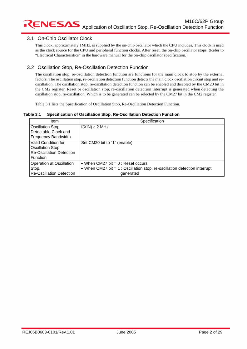
3.2 Oscillation Stop, Re-Oscillation Detection FunctionThe oscillation stop, re-oscillation detection function are functions for the main clock to stop by the externalfactors. The oscillation stop, re-oscillation detection function detects the main clock oscillation circuit stop and re-oscillation. The oscillation stop, re-oscillation detection function can be enabled and disabled by the CM20 bit inthe CM2 register. Reset or oscillation stop, re-oscillation detection interrupt is generated when detecting theoscillation stop, re-oscillation. Which is to be generated can be selected by the CM27 bit in the CM2 register.
Table 3.1 lists the Specification of Oscillation Stop, Re-Oscillation Detection Function.
Table 3.1 Specification of Oscillation Stop, Re-Oscillation Detection FunctionItem Specification
Oscillation Stop Detectable Clock andFrequency Bandwidth
f(XIN) ≥ 2 MHz
Valid Condition for Oscillation Stop,Re-Oscillation Detection Function
Set CM20 bit to “1” (enable)
Operation at Oscillation Stop,Re-Oscillation Detection
• When CM27 bit = 0 : Reset occurs• When CM27 bit = 1 : Oscillation stop, re-oscillation detection interrupt generated
REJ05B0603-0101/Rev.1.01 June 2005 Page 3 of 29
M16C/62P GroupApplication of Oscillation Stop, Re-Oscillation Detection Function
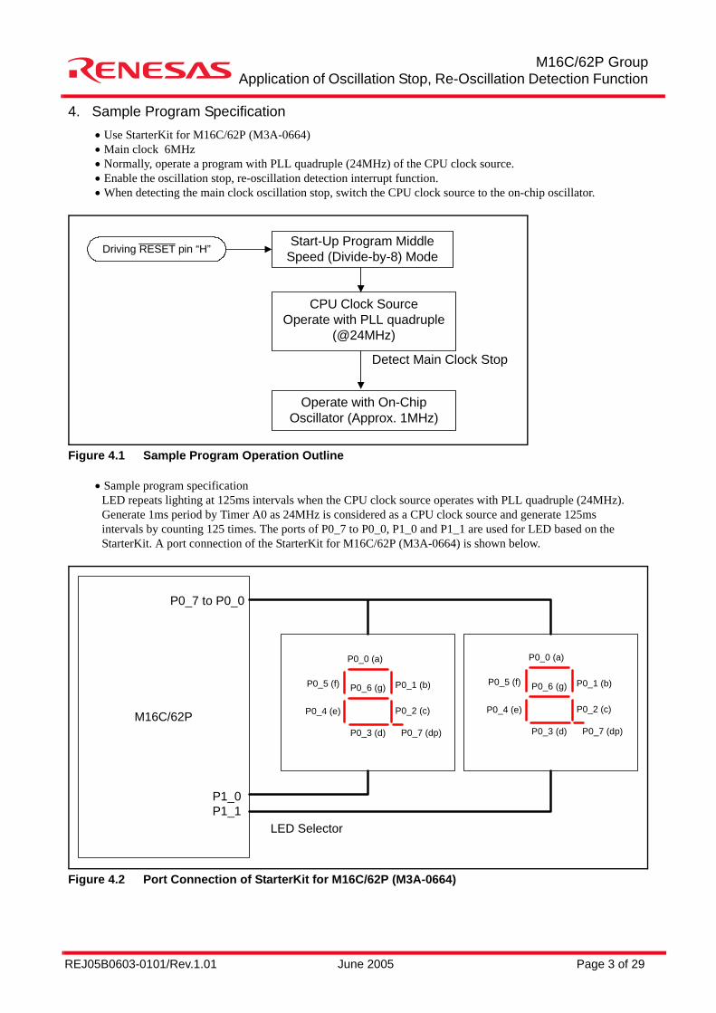
4. Sample Program Specification• Use StarterKit for M16C/62P (M3A-0664)• Main clock 6MHz• Normally, operate a program with PLL quadruple (24MHz) of the CPU clock source.• Enable the oscillation stop, re-oscillation detection interrupt function.• When detecting the main clock oscillation stop, switch the CPU clock source to the on-chip oscillator.
Figure 4.1 Sample Program Operation Outline
• Sample program specificationLED repeats lighting at 125ms intervals when the CPU clock source operates with PLL quadruple (24MHz). Generate 1ms period by Timer A0 as 24MHz is considered as a CPU clock source and generate 125ms intervals by counting 125 times. The ports of P0_7 to P0_0, P1_0 and P1_1 are used for LED based on the StarterKit. A port connection of the StarterKit for M16C/62P (M3A-0664) is shown below.
Figure 4.2 Port Connection of StarterKit for M16C/62P (M3A-0664)
Driving RESET pin “H” Start-Up Program MiddleSpeed (Divide-by-8) Mode
CPU Clock SourceOperate with PLL quadruple
(@24MHz)
Operate with On-ChipOscillator (Approx. 1MHz)
Detect Main Clock Stop
M16C/62P
P0_7 to P0_0
P1_0P1_1
P0_0 (a)
P0_1 (b)P0_6 (g)P0_5 (f)
P0_4 (e) P0_2 (c)
P0_3 (d) P0_7 (dp)
P0_0 (a)
P0_1 (b)P0_6 (g)P0_5 (f)
P0_4 (e) P0_2 (c)
P0_3 (d) P0_7 (dp)
LED Selector
REJ05B0603-0101/Rev.1.01 June 2005 Page 4 of 29
M16C/62P GroupApplication of Oscillation Stop, Re-Oscillation Detection Function
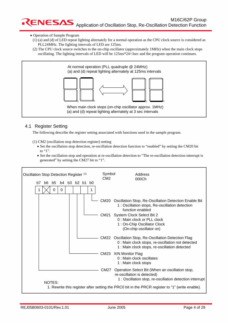
• Operation of Sample Program(1) (a) and (d) of LED repeat lighting alternately for a normal operation as the CPU clock source is considered as
PLL24MHz. The lighting intervals of LED are 125ms.(2) The CPU clock source switches to the on-chip oscillator (approximately 1MHz) when the main clock stops
oscillating. The lighting intervals of LED will be 125ms*24=3sec and the program operation continues.
4.1 Register SettingThe following describe the register setting associated with functions used in the sample program.
(1) CM2 (oscillation stop detection register) setting• Set the oscillation stop detection, re-oscillation detection function to “enabled” by setting the CM20 bit
to “1”.• Set the oscillation stop and operation at re-oscillation detection to “The re-oscillation detection interrupt is
generated” by setting the CM27 bit to “1”.
At normal operation (PLL quadruple @ 24MHz)(a) and (d) repeat lighting alternately at 125ms intervals
When main clock stops (on-chip oscillator approx. 1MHz)(a) and (d) repeat lighting alternately at 3 sec intervals
° ° ° °
Oscillation Stop Detection Register (1)
CM20 Oscillation Stop, Re-Oscillation Detection Enable Bit 1 : Oscillation stops, Re-oscillation detection function enabled
1 0
b7 b6 b5 b4 b3 b2 b1 b0
10
SymbolCM2
Address000Ch
CM21 System Clock Select Bit 2 0 : Main clock or PLL clock 1 : On-Chip Oscillator Clock (On-chip oscillator on)
CM22 Oscillation Stop, Re-Oscillation Detection Flag 0 : Main clock stops, re-oscillation not detected 1 : Main clock stops, re-oscillation detected
CM23 XIN Monitor Flag 0 : Main clock oscillates 1 : Main clock stops
CM27 Operation Select Bit (When an oscillation stop, re-oscillation is detected) 1 : Oscillation stop, re-oscillation detection interrupt
NOTES: 1. Rewrite this register after setting the PRC0 bit in the PRCR register to “1” (write enable).
REJ05B0603-0101/Rev.1.01 June 2005 Page 5 of 29
M16C/62P GroupApplication of Oscillation Stop, Re-Oscillation Detection Function
(2) Set fixed vector tableSet an interrupt process address of the oscillation stop, re-oscillation detection function to the vector address 0FFFF0h to 0FFFF3h of the fixed vector table. Refer to Interrupt in the M16C/62P group hardware manual for the fixed vector table and 6.1 sect30.inc (Section Definition File) and the sample program for detail settings.
(3) Process when the oscillation stop, re-oscillation detection interrupts is generatedThe oscillation stop, re-oscillation detection interrupts are generated by detecting the main clock stop or re-oscillation and the CM22 bit is set to “1”. At this time, the oscillation stop, re-oscillation detection interruptwill be disabled. Since the CM21 bit remains unchanged when the PLL clock is selected for the CPU clocksource, set to “1” in the interrupt process and the on-chip oscillation is selected for the CPU clock source.
(4) Determine main clock stateDetermine whether the main clock oscillates or stops by reading the CM23 bit several times in the oscillation stop and re-oscillation detection interrupt process.
REJ05B0603-0101/Rev.1.01 June 2005 Page 6 of 29
M16C/62P GroupApplication of Oscillation Stop, Re-Oscillation Detection Function
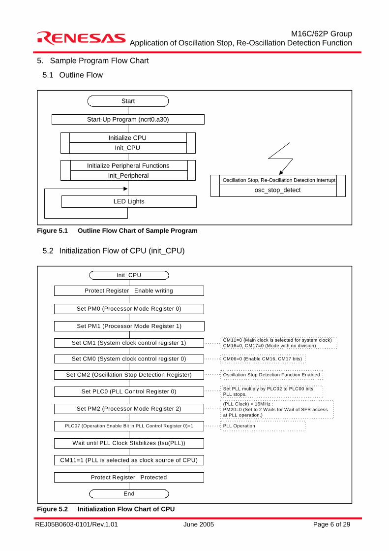
5. Sample Program Flow Chart
5.1 Outline Flow
Figure 5.1 Outline Flow Chart of Sample Program
5.2 Initialization Flow of CPU (init_CPU)
Figure 5.2 Initialization Flow Chart of CPU
Start
Start-Up Program (ncrt0.a30)
Initialize CPUInit_CPU
LED Lights
Initialize Peripheral FunctionsInit_Peripheral
Oscillation Stop, Re-Oscillation Detection Interrupt
osc_stop_detect
Init_CPU
Protect Register Enable writing
Set PM0 (Processor Mode Register 0)
Set CM1 (System clock control register 1)
Set CM0 (System clock control register 0)
Set CM2 (Oscillation Stop Detection Register)
Set PLC0 (PLL Control Register 0)
Set PM2 (Processor Mode Register 2)
PLC07 (Operation Enable Bit in PLL Control Register 0)=1
Wait until PLL Clock Stabilizes (tsu(PLL))
CM11=1 (PLL is selected as clock source of CPU)
Protect Register Protected
End
CM11=0 (Main clock is selected for system clock)CM16=0, CM17=0 (Mode with no division)
CM06=0 (Enable CM16, CM17 bits)
Oscillation Stop Detection Function Enabled
Set PLL multiply by PLC02 to PLC00 bits.PLL stops.
(PLL Clock) > 16MHz :PM20=0 (Set to 2 Waits for Wait of SFR accessat PLL operation.)
PLL Operation
Set PM1 (Processor Mode Register 1)
REJ05B0603-0101/Rev.1.01 June 2005 Page 7 of 29
M16C/62P GroupApplication of Oscillation Stop, Re-Oscillation Detection Function
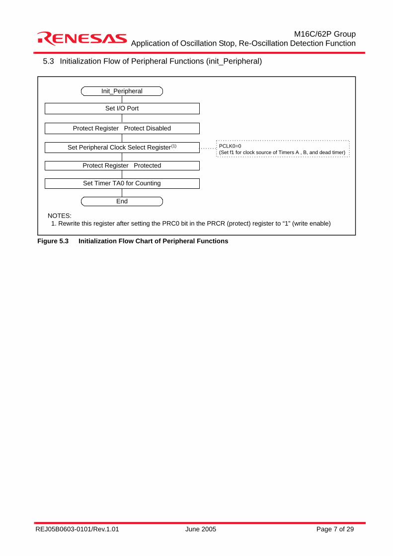
5.3 Initialization Flow of Peripheral Functions (init_Peripheral)
Figure 5.3 Initialization Flow Chart of Peripheral Functions
Init_Peripheral
Set I/O Port
Protect Register Protect Disabled
Set Peripheral Clock Select Register(1)
Protect Register Protected
Set Timer TA0 for Counting
End
PCLK0=0(Set f1 for clock source of Timers A , B, and dead timer)
NOTES: 1. Rewrite this register after setting the PRC0 bit in the PRCR (protect) register to “1” (write enable)
REJ05B0603-0101/Rev.1.01 June 2005 Page 8 of 29
M16C/62P GroupApplication of Oscillation Stop, Re-Oscillation Detection Function
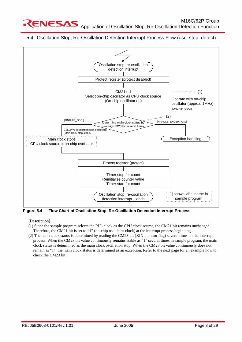
5.4 Oscillation Stop, Re-Oscillation Detection Interrupt Process Flow (osc_stop_detect)
Figure 5.4 Flow Chart of Oscillation Stop, Re-Oscillation Detection Interrupt Process
[Description](1) Since the sample program selects the PLL clock as the CPU clock source, the CM21 bit remains unchanged.
Therefore, the CM21 bit is set to “1” (on-chip oscillator clock) at the interrupt process beginning.(2) The main clock status is determined by reading the CM23 bit (XIN monitor flag) several times in the interrupt
process. When the CM23 bit value continuously remains stable as “1” several times in sample program, the main clock status is determined as the main clock oscillation stop. When the CM23 bit value continuously does not remain as “1”, the main clock status is determined as an exception. Refer to the next page for an example how to check the CM23 bit.
Oscillation stop, re-oscillationdetection interrupt
Protect register (protect disabled)
CM21←1Select on-chip oscillator as CPU clock source
(On-chip oscillator on)
Exception handlingMain clock stopsCPU clock source = on-chip oscillator
(1)
Operate with on-chiposcillator (approx. 1MHz)
Determine main clock status byreading CM23 bit several times
CM23==1 (oscillation stop detection)(Main clock stop status)
[ONCHIP_OSC:](2)
Protect register (protect)
Timer stop for countReinitialize counter value
Timer start for count
Oscillation stop, re-oscillationdetection interrupt ends
[ ] shows label name insample program
[ONCHIP_OSC:]
[HANDLE_EXCEPTION:]
REJ05B0603-0101/Rev.1.01 June 2005 Page 9 of 29
M16C/62P GroupApplication of Oscillation Stop, Re-Oscillation Detection Function
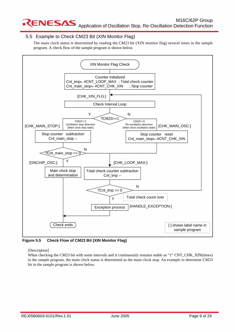
5.5 Example to Check CM23 Bit (XIN Monitor Flag)The main clock status is determined by reading the CM23 bit (XIN monitor flag) several times in the sampleprogram. A check flow of the sample program is shown below.
Figure 5.5 Check Flow of CM23 Bit (XIN Monitor Flag)
[Description]When checking the CM23 bit with some intervals and it continuously remains stable as “1” CNT_CHK_XIN(times)in the sample program, the main clock status is determined as the main clock stop. An example to determine CM23bit in the sample program is shown below.
XIN Monitor Flag Check
Check Interval Loop
Counter initializedCnt_tmp←#CNT_LOOP_MAX ; Total check counterCnt_main_stop←#CNT_CHK_XIN ; Stop counter
Check ends
Total check count over
[CHK_XIN_FLG:]
?CM23==1CM23==1
Oscillation stop detection(Main clock stop state)
CM23==0Re-oscillation detection
(Main clock oscillation state)
N
Exception process
[ ] shows label name insample program
Y
Stop counter subtractionCnt_main_stop --
Stop counter resetCnt_main_stop←#CNT_CHK_XIN
[CHK_MAIN_STOP:] [CHK_MAIN_OSC:]
?Cnt_main_stop == 0
Main clock stopand determination
[ONCHIP_OSC:] Y
N
Total check counter subtractionCnt_tmp --
[CHK_LOOP_MAX:]
?Cnt_tmp == 0N
Y
[HANDLE_EXCEPTION:]
REJ05B0603-0101/Rev.1.01 June 2005 Page 10 of 29
M16C/62P GroupApplication of Oscillation Stop, Re-Oscillation Detection Function
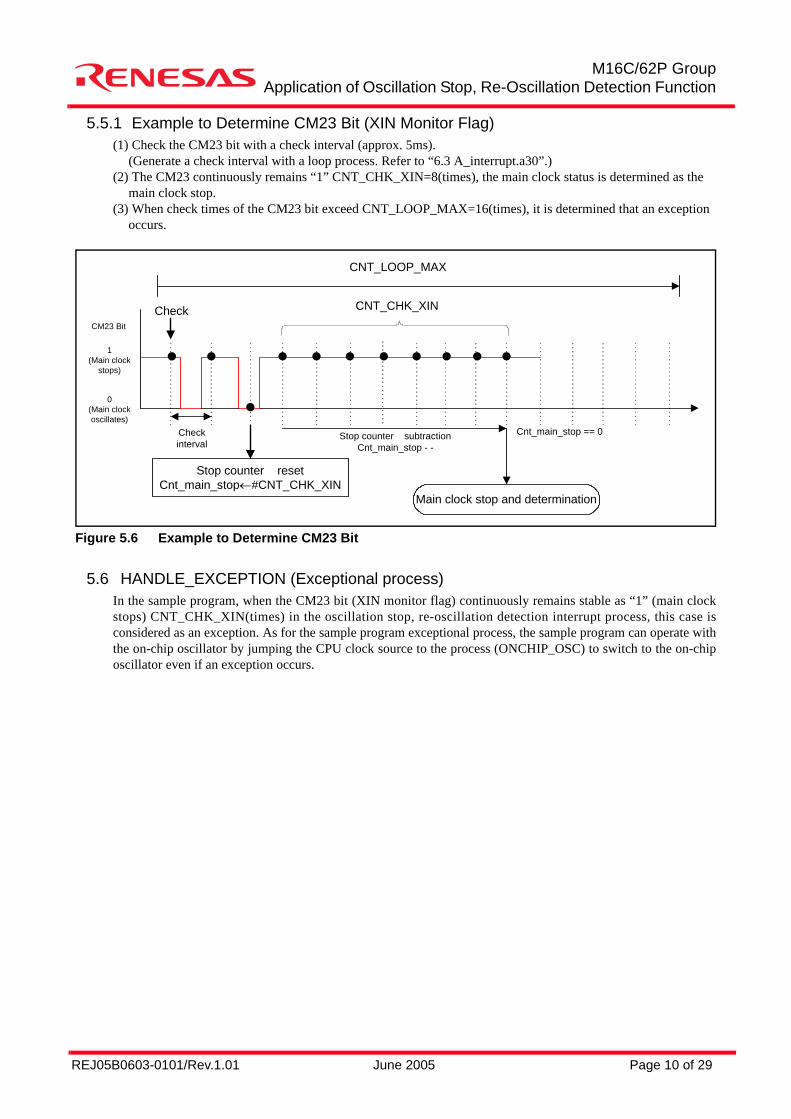
5.5.1 Example to Determine CM23 Bit (XIN Monitor Flag)(1) Check the CM23 bit with a check interval (approx. 5ms).
(Generate a check interval with a loop process. Refer to “6.3 A_interrupt.a30”.)(2) The CM23 continuously remains “1” CNT_CHK_XIN=8(times), the main clock status is determined as the
main clock stop.(3) When check times of the CM23 bit exceed CNT_LOOP_MAX=16(times), it is determined that an exception
occurs.
Figure 5.6 Example to Determine CM23 Bit
5.6 HANDLE_EXCEPTION (Exceptional process)In the sample program, when the CM23 bit (XIN monitor flag) continuously remains stable as “1” (main clockstops) CNT_CHK_XIN(times) in the oscillation stop, re-oscillation detection interrupt process, this case isconsidered as an exception. As for the sample program exceptional process, the sample program can operate withthe on-chip oscillator by jumping the CPU clock source to the process (ONCHIP_OSC) to switch to the on-chiposcillator even if an exception occurs.
Main clock stop and determination
Stop counter resetCnt_main_stop←#CNT_CHK_XIN
CNT_LOOP_MAX
Check CNT_CHK_XIN
Checkinterval
Stop counter subtractionCnt_main_stop - -
Cnt_main_stop == 0
CM23 Bit
1(Main clock
stops)
0(Main clockoscillates)
REJ05B0603-0101/Rev.1.01 June 2005 Page 11 of 29
M16C/62P GroupApplication of Oscillation Stop, Re-Oscillation Detection Function
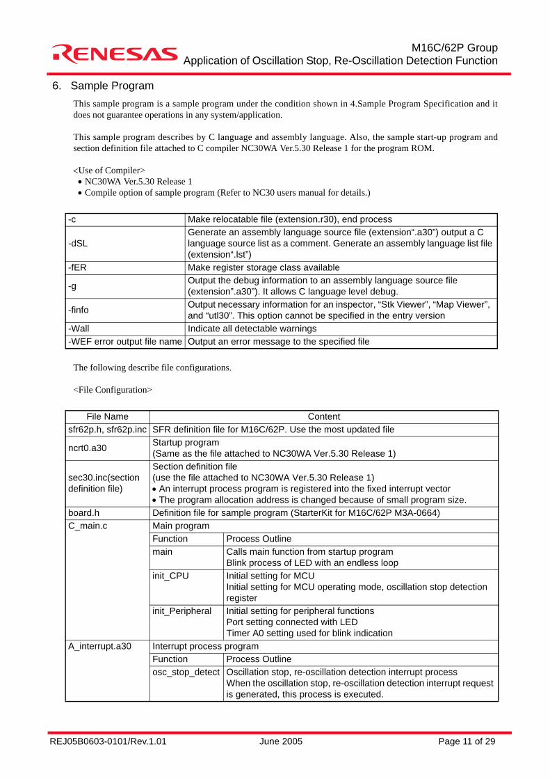
6. Sample ProgramThis sample program is a sample program under the condition shown in 4.Sample Program Specification and itdoes not guarantee operations in any system/application.
This sample program describes by C language and assembly language. Also, the sample start-up program andsection definition file attached to C compiler NC30WA Ver.5.30 Release 1 for the program ROM.
<Use of Compiler>• NC30WA Ver.5.30 Release 1• Compile option of sample program (Refer to NC30 users manual for details.)
The following describe file configurations.
<File Configuration>
-c Make relocatable file (extension.r30), end process
-dSLGenerate an assembly language source file (extension“.a30”) output a C language source list as a comment. Generate an assembly language list file (extension“.lst”)
-fER Make register storage class available
-g Output the debug information to an assembly language source file (extension”.a30”). It allows C language level debug.
-finfo Output necessary information for an inspector, “Stk Viewer”, “Map Viewer”, and “utl30”. This option cannot be specified in the entry version
-Wall Indicate all detectable warnings-WEF error output file name Output an error message to the specified file
File Name Contentsfr62p.h, sfr62p.inc SFR definition file for M16C/62P. Use the most updated file
ncrt0.a30 Startup program(Same as the file attached to NC30WA Ver.5.30 Release 1)
sec30.inc(section definition file)
Section definition file(use the file attached to NC30WA Ver.5.30 Release 1)• An interrupt process program is registered into the fixed interrupt vector• The program allocation address is changed because of small program size.
board.h Definition file for sample program (StarterKit for M16C/62P M3A-0664)C_main.c Main program
Function Process Outlinemain Calls main function from startup program
Blink process of LED with an endless loopinit_CPU Initial setting for MCU
Initial setting for MCU operating mode, oscillation stop detection register
init_Peripheral Initial setting for peripheral functionsPort setting connected with LEDTimer A0 setting used for blink indication
A_interrupt.a30 Interrupt process programFunction Process Outlineosc_stop_detect Oscillation stop, re-oscillation detection interrupt process
When the oscillation stop, re-oscillation detection interrupt request is generated, this process is executed.
REJ05B0603-0101/Rev.1.01 June 2005 Page 12 of 29
M16C/62P GroupApplication of Oscillation Stop, Re-Oscillation Detection Function
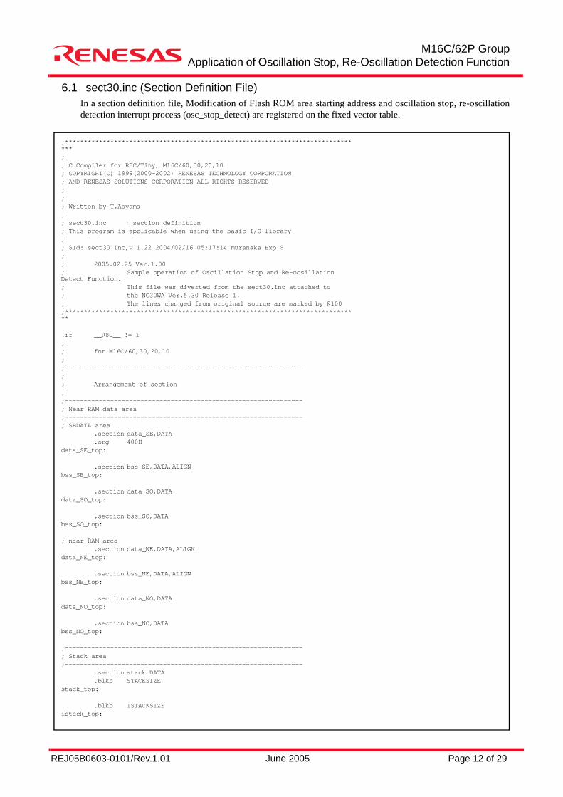
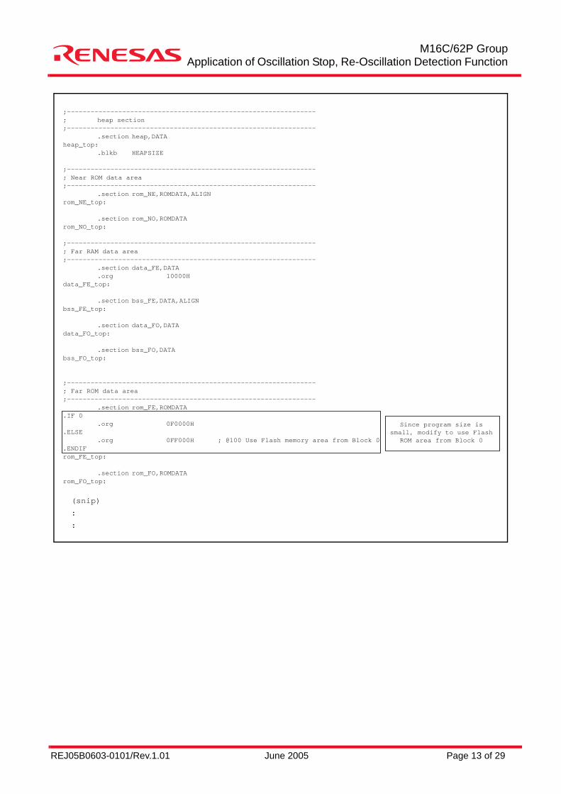
6.1 sect30.inc (Section Definition File)In a section definition file, Modification of Flash ROM area starting address and oscillation stop, re-oscillationdetection interrupt process (osc_stop_detect) are registered on the fixed vector table.
;*******************************************************************************;; C Compiler for R8C/Tiny, M16C/60,30,20,10; COPYRIGHT(C) 1999(2000-2002) RENESAS TECHNOLOGY CORPORATION; AND RENESAS SOLUTIONS CORPORATION ALL RIGHTS RESERVED;;; Written by T.Aoyama;; sect30.inc : section definition; This program is applicable when using the basic I/O library;; $Id: sect30.inc,v 1.22 2004/02/16 05:17:14 muranaka Exp $;; 2005.02.25 Ver.1.00; Sample operation of Oscillation Stop and Re-ocsillationDetect Function.; This file was diverted from the sect30.inc attached to; the NC30WA Ver.5.30 Release 1.; The lines changed from original source are marked by @100;******************************************************************************
.if __R8C__ != 1;; for M16C/60,30,20,10;;---------------------------------------------------------------;; Arrangement of section;;---------------------------------------------------------------; Near RAM data area;---------------------------------------------------------------; SBDATA area
.section data_SE,DATA
.org 400Hdata_SE_top:
.section bss_SE,DATA,ALIGNbss_SE_top:
.section data_SO,DATAdata_SO_top:
.section bss_SO,DATAbss_SO_top:
; near RAM area.section data_NE,DATA,ALIGN
data_NE_top:
.section bss_NE,DATA,ALIGNbss_NE_top:
.section data_NO,DATAdata_NO_top:
.section bss_NO,DATAbss_NO_top:
;---------------------------------------------------------------; Stack area;---------------------------------------------------------------
.section stack,DATA
.blkb STACKSIZEstack_top:
.blkb ISTACKSIZEistack_top:
REJ05B0603-0101/Rev.1.01 June 2005 Page 13 of 29
M16C/62P GroupApplication of Oscillation Stop, Re-Oscillation Detection Function
;---------------------------------------------------------------; heap section;---------------------------------------------------------------
.section heap,DATAheap_top:
.blkb HEAPSIZE
;---------------------------------------------------------------; Near ROM data area;---------------------------------------------------------------
.section rom_NE,ROMDATA,ALIGNrom_NE_top:
.section rom_NO,ROMDATArom_NO_top:
;---------------------------------------------------------------; Far RAM data area;---------------------------------------------------------------
.section data_FE,DATA
.org 10000Hdata_FE_top:
.section bss_FE,DATA,ALIGNbss_FE_top:
.section data_FO,DATAdata_FO_top:
.section bss_FO,DATAbss_FO_top:
;---------------------------------------------------------------; Far ROM data area;---------------------------------------------------------------
.section rom_FE,ROMDATA.IF 0
.org 0F0000H.ELSE
.org 0FF000H ; @100 Use Flash memory area from Block 0.ENDIFrom_FE_top:
.section rom_FO,ROMDATArom_FO_top:
(snip)
:
:
Since program size issmall, modify to use Flash
ROM area from Block 0
REJ05B0603-0101/Rev.1.01 June 2005 Page 14 of 29
M16C/62P GroupApplication of Oscillation Stop, Re-Oscillation Detection Function
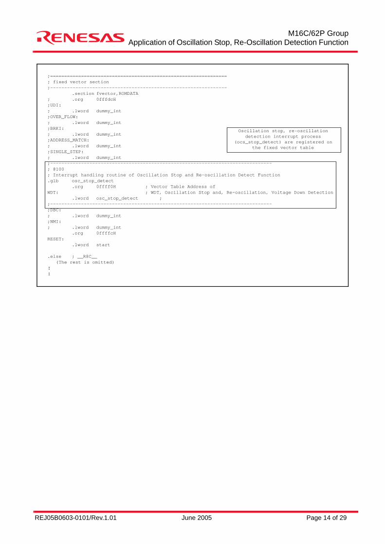
;===============================================================; fixed vector section;---------------------------------------------------------------
.section fvector,ROMDATA; .org 0fffdcH;UDI:; .lword dummy_int;OVER_FLOW:; .lword dummy_int;BRKI:; .lword dummy_int;ADDRESS_MATCH:; .lword dummy_int;SINGLE_STEP:; .lword dummy_int;-------------------------------------------------------------------------------; @100; Interrupt handling routine of Oscillation Stop and Re-oscillation Detect Function.glb osc_stop_detect
.org 0ffff0H ; Vector Table Address ofWDT: ; WDT, Oscillation Stop and, Re-oscillation, Voltage Down Detection
.lword osc_stop_detect ;;-------------------------------------------------------------------------------;DBC:; .lword dummy_int;NMI:; .lword dummy_int
.org 0ffffcHRESET:
.lword start
.else ; __R8C__ (The rest is omitted)::
Oscillation stop, re-oscillationdetection interrupt process
(ocs_stop_detect) are registered onthe fixed vector table
REJ05B0603-0101/Rev.1.01 June 2005 Page 15 of 29
M16C/62P GroupApplication of Oscillation Stop, Re-Oscillation Detection Function
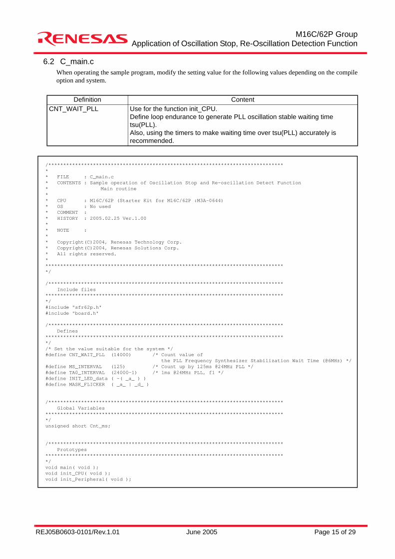
6.2 C_main.cWhen operating the sample program, modify the setting value for the following values depending on the compileoption and system.
Definition ContentCNT_WAIT_PLL Use for the function init_CPU.
Define loop endurance to generate PLL oscillation stable waiting time tsu(PLL).Also, using the timers to make waiting time over tsu(PLL) accurately is recommended.
/********************************************************************************* FILE : C_main.c* CONTENTS : Sample operation of Oscillation Stop and Re-oscillation Detect Function* Main routine** CPU : M16C/62P (Starter Kit for M16C/62P :M3A-0644)* OS : No used* COMMENT :* HISTORY : 2005.02.25 Ver.1.00** NOTE :** Copyright(C)2004, Renesas Technology Corp.* Copyright(C)2004, Renesas Solutions Corp.* All rights reserved.**********************************************************************************/
/******************************************************************************* Include files*********************************************************************************/#include "sfr62p.h"#include "board.h"
/******************************************************************************* Defines*********************************************************************************//* Set the value suitable for the system */#define CNT_WAIT_PLL (14000) /* Count value of the PLL Frequency Synthesizer Stabilization Wait Time (@6MHz) */#define MS_INTERVAL (125) /* Count up by 125ms @24MHz PLL */#define TA0_INTERVAL (24000-1) /* 1ms @24MHz PLL, f1 */#define INIT_LED_data ( ~( _a_ ) )#define MASK_FLICKER ( _a_ | _d_ )
/******************************************************************************* Global Variables*********************************************************************************/unsigned short Cnt_ms;
/******************************************************************************* Prototypes*********************************************************************************/void main( void );void init_CPU( void );void init_Peripheral( void );
REJ05B0603-0101/Rev.1.01 June 2005 Page 16 of 29
M16C/62P GroupApplication of Oscillation Stop, Re-Oscillation Detection Function
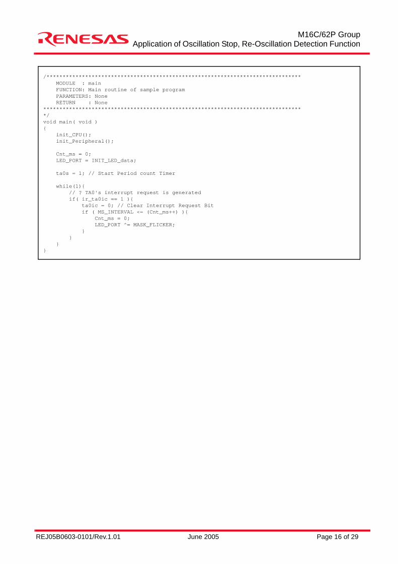
/******************************************************************************* MODULE : main FUNCTION: Main routine of sample program PARAMETERS: None RETURN : None*********************************************************************************/void main( void ){ init_CPU(); init_Peripheral();
Cnt_ms = 0; LED_PORT = INIT_LED_data;
ta0s = 1; // Start Period count Timer
while(1){ // ? TA0's interrupt request is generated if( ir_ta0ic == 1 ){ ta0ic = 0; // Clear Interrupt Request Bit if ( MS_INTERVAL <= (Cnt_ms++) ){ Cnt_ms = 0; LED_PORT ^= MASK_FLICKER; } } }}
REJ05B0603-0101/Rev.1.01 June 2005 Page 17 of 29
M16C/62P GroupApplication of Oscillation Stop, Re-Oscillation Detection Function
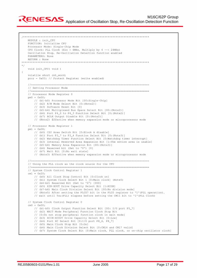
/******************************************************************************* MODULE : init_CPU FUNCTION: Initialize CPU Processor Mode: Single-Chip Mode CPU Clock: PLL Clock (Xin = 6MHz, Multiply by 4 --> 24MHz) Oscillation Stop, Re-Oscillation Detection function enabled PARAMETERS: None RETURN : None*********************************************************************************/ void init_CPU( void ){ volatile short cnt_word; prcr = 0x03; // Protect Register (write enabled)
//========================================================================== // Setting Processor Mode //========================================================================== // Processor Mode Register 0 pm0 = 0x00; // (b1-b0) Processor Mode Bit [00:Single-Chip] // (b2) R/W Mode Select Bit [0:(Note2)] // (b3) Software Reset Bit [0] // (b5-b4) Multiplexed Bus Space Select Bit [00:(Note2)] // (b6) Port P4_0 to P4_3 Function Select Bit [0:(Note2)] // (b7) BCLK Output Disable Bit [0:(Note2)] // (Note2) Effective when memory expansion mode or microprocessor mode
// Processor Mode Register 1 pm1 = 0x08; // (b0) CS2 Area Switch Bit [0:Block A disable] // (b1) Port P3_7 to P3_4 Function Select Bit [0:(Note3)] // (b2) Watchdog Timer Function Select Bit [0:Watchdog timer interrupt] // (b3) Internal Reserved Area Expansion Bit [1:The entire area is usable] // (b5-b4) Memory Area Expansion Bit [00:(Note3)] // (b6) Reserved bit (Set to "0") [0] // (b7) Wait Bit [0:No wait state] // (Note3) Effective when memory expansion mode or microprocessor mode
//========================================================================== // Using the PLL clock as the clock source for the CPU //========================================================================== // System Clock Control Register 1 cm1 = 0x20; // (b0) All Clock Stop Control Bit [0:Clock on] // (b1) System Clock Select Bit 1 [0:Main clock] (Note5) // (b4-b2) Reserved Bit (Set to "0") [000] // (b5) XIN-XOUT Drive Capacity Select Bit [1:HIGH] // (b7-b6) Main Clock Division Select Bit [00:No division mode] // (Note5) After setting the PLC07 bit in the PLC0 register to "1"(PLL operation), // wait until Tsu(PLL) elapses before setting the CM11 bit to "1"(PLL Clock)
// System Clock Control Register 0 cm0 = 0x00; // (b1-b0) Clock Output Function Select Bit [00: I/O port P5_7] // (b2) WAIT Mode Peripheral Function Clock Stop Bit // [0:Do not stop peripheral function clock in wait mode] // (b3) XCIN-XCOUT Drive Capacity Select Bit [0:Low] // (b4) Port XC Select Bit [0:I/O port P8_6, P8_7] // (b5) Main Clock Stop Bit [0:On] // (b6) Main Clock Division Select Bit [0:CM16 and CM17 valid] // (b7) System Clock Select Bit [0:Main clock, PLL clock, or on-chip oscillator clock]
REJ05B0603-0101/Rev.1.01 June 2005 Page 18 of 29
M16C/62P GroupApplication of Oscillation Stop, Re-Oscillation Detection Function
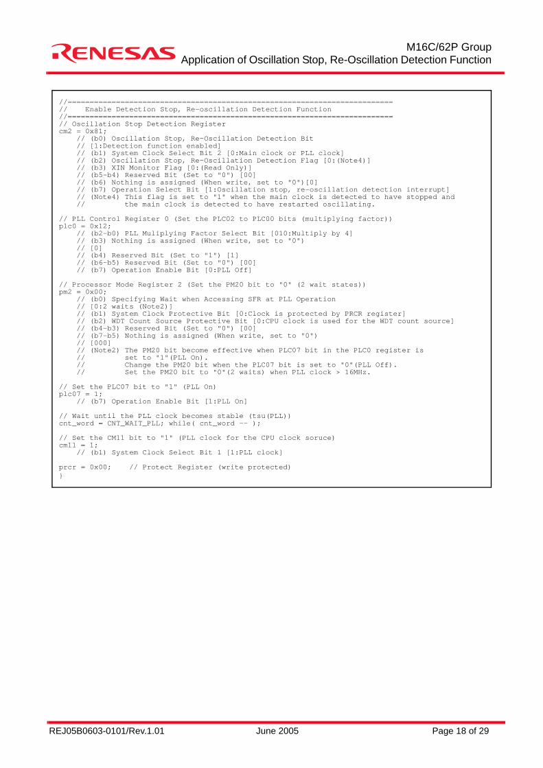
//==========================================================================// Enable Detection Stop, Re-oscillation Detection Function//==========================================================================// Oscillation Stop Detection Registercm2 = 0x81; // (b0) Oscillation Stop, Re-Oscillation Detection Bit // [1:Detection function enabled] // (b1) System Clock Select Bit 2 [0:Main clock or PLL clock] // (b2) Oscillation Stop, Re-Oscillation Detection Flag [0:(Note4)] // (b3) XIN Monitor Flag [0:(Read Only)] // (b5-b4) Reserved Bit (Set to "0") [00] // (b6) Nothing is assigned (When write, set to "0")[0] // (b7) Operation Select Bit [1:Oscillation stop, re-oscillation detection interrupt] // (Note4) This flag is set to "1" when the main clock is detected to have stopped and // the main clock is detected to have restarted oscillating.
// PLL Control Register 0 (Set the PLC02 to PLC00 bits (multiplying factor))plc0 = 0x12; // (b2-b0) PLL Muliplying Factor Select Bit [010:Multiply by 4] // (b3) Nothing is assigned (When write, set to "0") // [0] // (b4) Reserved Bit (Set to "1") [1] // (b6-b5) Reserved Bit (Set to "0") [00] // (b7) Operation Enable Bit [0:PLL Off]
// Processor Mode Register 2 (Set the PM20 bit to "0" (2 wait states))pm2 = 0x00; // (b0) Specifying Wait when Accessing SFR at PLL Operation // [0:2 waits (Note2)] // (b1) System Clock Protective Bit [0:Clock is protected by PRCR register] // (b2) WDT Count Source Protective Bit [0:CPU clock is used for the WDT count source] // (b4-b3) Reserved Bit (Set to "0") [00] // (b7-b5) Nothing is assigned (When write, set to "0") // [000] // (Note2) The PM20 bit become effective when PLC07 bit in the PLC0 register is // set to "1"(PLL On). // Change the PM20 bit when the PLC07 bit is set to "0"(PLL Off). // Set the PM20 bit to "0"(2 waits) when PLL clock > 16MHz.
// Set the PLC07 bit to "1" (PLL On)plc07 = 1; // (b7) Operation Enable Bit [1:PLL On]
// Wait until the PLL clock becomes stable (tsu(PLL))cnt_word = CNT_WAIT_PLL; while( cnt_word -- );
// Set the CM11 bit to "1" (PLL clock for the CPU clock soruce)cm11 = 1; // (b1) System Clock Select Bit 1 [1:PLL clock]
prcr = 0x00; // Protect Register (write protected)}
REJ05B0603-0101/Rev.1.01 June 2005 Page 19 of 29
M16C/62P GroupApplication of Oscillation Stop, Re-Oscillation Detection Function
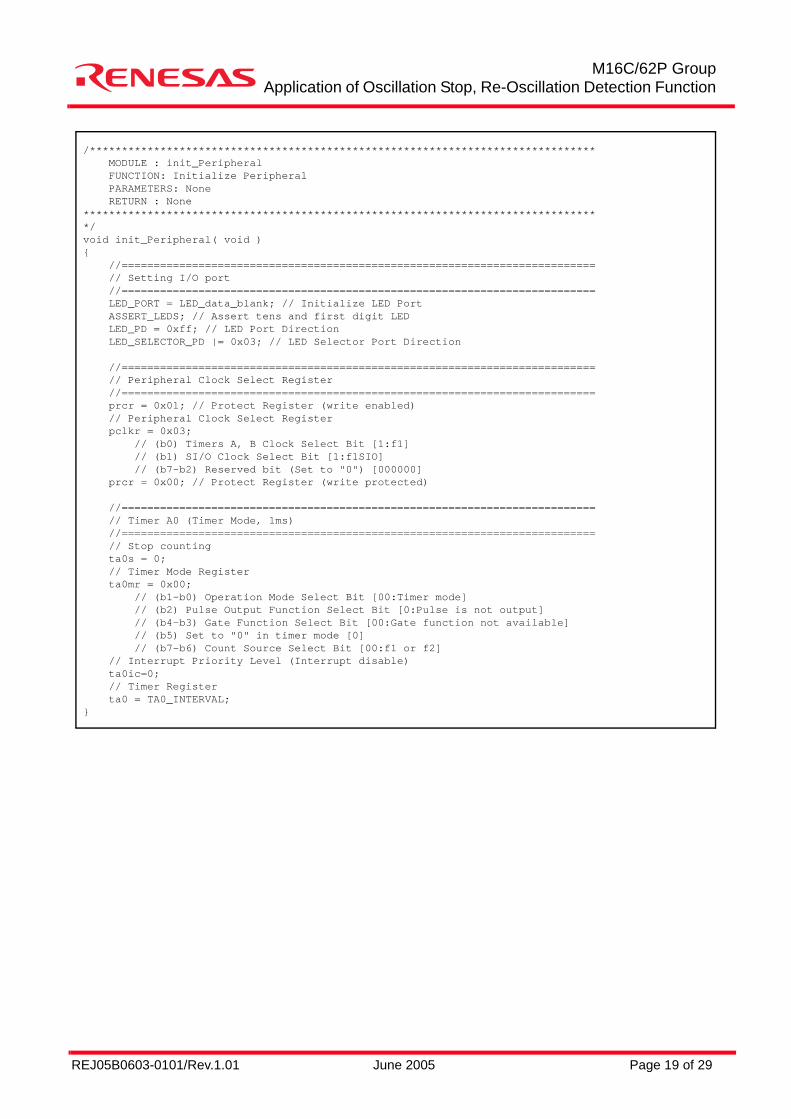
/******************************************************************************* MODULE : init_Peripheral FUNCTION: Initialize Peripheral PARAMETERS: None RETURN : None*********************************************************************************/void init_Peripheral( void ){ //========================================================================== // Setting I/O port //========================================================================== LED_PORT = LED_data_blank; // Initialize LED Port ASSERT_LEDS; // Assert tens and first digit LED LED_PD = 0xff; // LED Port Direction LED_SELECTOR_PD |= 0x03; // LED Selector Port Direction
//========================================================================== // Peripheral Clock Select Register //========================================================================== prcr = 0x01; // Protect Register (write enabled) // Peripheral Clock Select Register pclkr = 0x03; // (b0) Timers A, B Clock Select Bit [1:f1] // (b1) SI/O Clock Select Bit [1:f1SIO] // (b7-b2) Reserved bit (Set to "0") [000000] prcr = 0x00; // Protect Register (write protected)
//========================================================================== // Timer A0 (Timer Mode, 1ms) //========================================================================== // Stop counting ta0s = 0; // Timer Mode Register ta0mr = 0x00; // (b1-b0) Operation Mode Select Bit [00:Timer mode] // (b2) Pulse Output Function Select Bit [0:Pulse is not output] // (b4-b3) Gate Function Select Bit [00:Gate function not available] // (b5) Set to "0" in timer mode [0] // (b7-b6) Count Source Select Bit [00:f1 or f2] // Interrupt Priority Level (Interrupt disable) ta0ic=0; // Timer Register ta0 = TA0_INTERVAL;}
REJ05B0603-0101/Rev.1.01 June 2005 Page 20 of 29
M16C/62P GroupApplication of Oscillation Stop, Re-Oscillation Detection Function
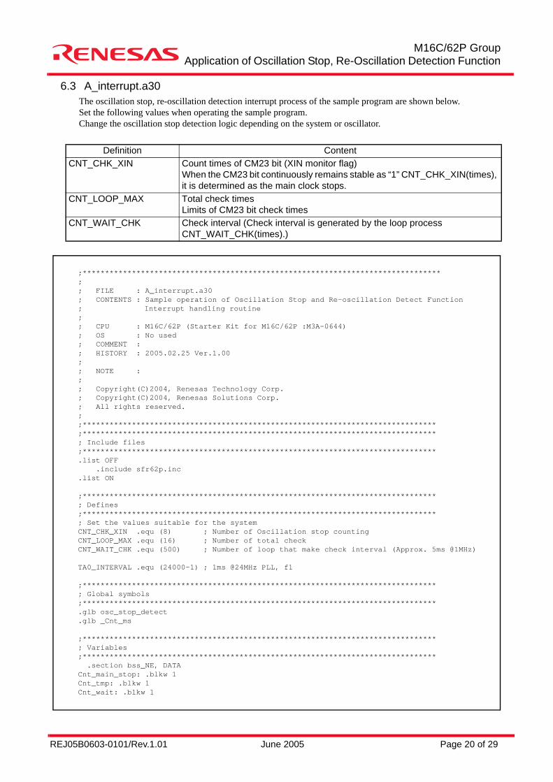
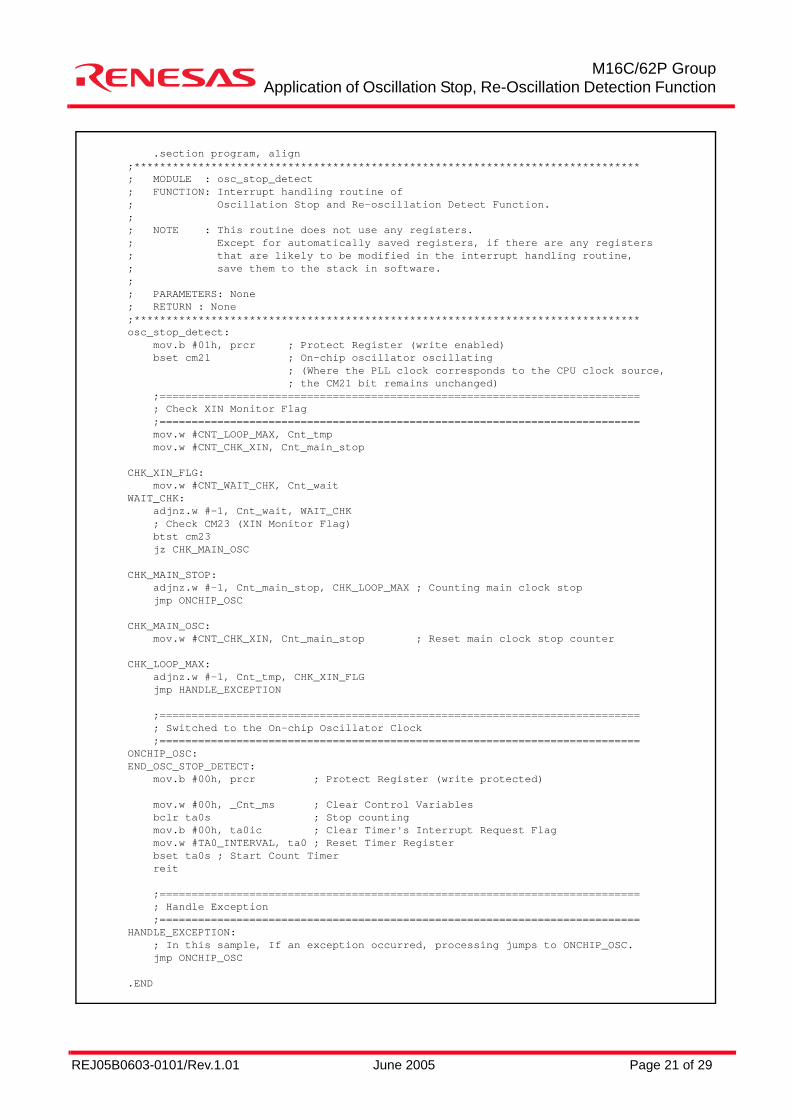
6.3 A_interrupt.a30The oscillation stop, re-oscillation detection interrupt process of the sample program are shown below.Set the following values when operating the sample program.Change the oscillation stop detection logic depending on the system or oscillator.
Definition ContentCNT_CHK_XIN Count times of CM23 bit (XIN monitor flag)
When the CM23 bit continuously remains stable as “1” CNT_CHK_XIN(times), it is determined as the main clock stops.
CNT_LOOP_MAX Total check timesLimits of CM23 bit check times
CNT_WAIT_CHK Check interval (Check interval is generated by the loop process CNT_WAIT_CHK(times).)
;********************************************************************************;; FILE : A_interrupt.a30; CONTENTS : Sample operation of Oscillation Stop and Re-oscillation Detect Function; Interrupt handling routine;; CPU : M16C/62P (Starter Kit for M16C/62P :M3A-0644); OS : No used; COMMENT :; HISTORY : 2005.02.25 Ver.1.00;; NOTE :;; Copyright(C)2004, Renesas Technology Corp.; Copyright(C)2004, Renesas Solutions Corp.; All rights reserved.;;*******************************************************************************;*******************************************************************************; Include files;*******************************************************************************.list OFF .include sfr62p.inc.list ON
;*******************************************************************************; Defines;*******************************************************************************; Set the values suitable for the systemCNT_CHK_XIN .equ (8) ; Number of Oscillation stop countingCNT_LOOP_MAX .equ (16) ; Number of total checkCNT_WAIT_CHK .equ (500) ; Number of loop that make check interval (Approx. 5ms @1MHz)
TA0_INTERVAL .equ (24000-1) ; 1ms @24MHz PLL, f1
;*******************************************************************************; Global symbols;*******************************************************************************.glb osc_stop_detect.glb _Cnt_ms
;*******************************************************************************; Variables;******************************************************************************* .section bss_NE, DATACnt_main_stop: .blkw 1Cnt_tmp: .blkw 1Cnt_wait: .blkw 1
REJ05B0603-0101/Rev.1.01 June 2005 Page 21 of 29
M16C/62P GroupApplication of Oscillation Stop, Re-Oscillation Detection Function
.section program, align;*******************************************************************************; MODULE : osc_stop_detect; FUNCTION: Interrupt handling routine of; Oscillation Stop and Re-oscillation Detect Function.;; NOTE : This routine does not use any registers.; Except for automatically saved registers, if there are any registers; that are likely to be modified in the interrupt handling routine,; save them to the stack in software.;; PARAMETERS: None; RETURN : None;*******************************************************************************osc_stop_detect: mov.b #01h, prcr ; Protect Register (write enabled) bset cm21 ; On-chip oscillator oscillating ; (Where the PLL clock corresponds to the CPU clock source, ; the CM21 bit remains unchanged) ;=========================================================================== ; Check XIN Monitor Flag ;=========================================================================== mov.w #CNT_LOOP_MAX, Cnt_tmp mov.w #CNT_CHK_XIN, Cnt_main_stop
CHK_XIN_FLG: mov.w #CNT_WAIT_CHK, Cnt_waitWAIT_CHK: adjnz.w #-1, Cnt_wait, WAIT_CHK ; Check CM23 (XIN Monitor Flag) btst cm23 jz CHK_MAIN_OSC
CHK_MAIN_STOP: adjnz.w #-1, Cnt_main_stop, CHK_LOOP_MAX ; Counting main clock stop jmp ONCHIP_OSC
CHK_MAIN_OSC: mov.w #CNT_CHK_XIN, Cnt_main_stop ; Reset main clock stop counter
CHK_LOOP_MAX: adjnz.w #-1, Cnt_tmp, CHK_XIN_FLG jmp HANDLE_EXCEPTION
;=========================================================================== ; Switched to the On-chip Oscillator Clock ;===========================================================================ONCHIP_OSC:END_OSC_STOP_DETECT: mov.b #00h, prcr ; Protect Register (write protected)
mov.w #00h, _Cnt_ms ; Clear Control Variables bclr ta0s ; Stop counting mov.b #00h, ta0ic ; Clear Timer's Interrupt Request Flag mov.w #TA0_INTERVAL, ta0 ; Reset Timer Register bset ta0s ; Start Count Timer reit
;=========================================================================== ; Handle Exception ;===========================================================================HANDLE_EXCEPTION: ; In this sample, If an exception occurred, processing jumps to ONCHIP_OSC. jmp ONCHIP_OSC
.END
REJ05B0603-0101/Rev.1.01 June 2005 Page 22 of 29
M16C/62P GroupApplication of Oscillation Stop, Re-Oscillation Detection Function
7. Reference DocumentHardware Manual
M16C/62P Group Hardware Manual Rev.2.30(Use the latest version on the Renesas Technology Corporation Semiconductor Home Page)
Technical Update/Technical News(Use the latest version on the Renesas Technology Corporation Semiconductor Home Page)
8. Home Page and E-mail SupportRenesas Technology Corporation Semiconductor Home Pagehttp://www.renesas.com
M16C Family MCU Technical E-mail SupportE-mail: [email protected]
REJ05B0603-0101/Rev.1.01 June 2005 Page 23 of 29
M16C/62P GroupApplication of Oscillation Stop, Re-Oscillation Detection Function
Appendix 1.Registers Associated with Oscillation Stop, Re-Oscillation Detection FunctionThis sample program is referred to the following hardware manual:• Referred hardware manual : M16C/62P Group hardware manual Rev.2.30Refer to the latest hardware manual for specifications or functions of each register.
REJ05B0603-0101/Rev.1.01 June 2005 Page 24 of 29
M16C/62P GroupApplication of Oscillation Stop, Re-Oscillation Detection Function
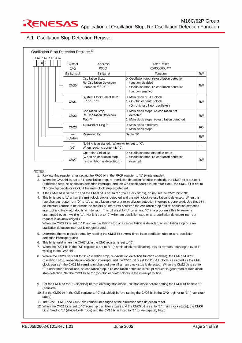
A.1 Oscillation Stop Detection Register
Oscillation Stop Detection Register (1)
Symbol Address After ResetCM2 000Ch 0X000000b (11)
Bit Symbol Bit Name Function RW
NOTES :1.2.
3.4.
5.
6.7.
8.
9.
10.
11.12.
CM21 RW
CM20 RW
Oscillation Stop,Re-Oscillation DetectionEnable Bit (7, 9, 10,11)
0: Oscillation stop, re-oscillation detection function disabled1: Oscillation stop, re-oscillation detection function enabled
0: Main clock or PLL clock1: On-chip oscillator clock (On-chip oscillator oscillates)
Where the CM20 bit is set to “1” (oscillation stop, re-oscillation detection function enabled), the CM27 bit is “1”(oscillation stop, re-oscillation detection interrupt), and the CM11 bit is set to “1” (PLL clock is selected as the CPUclock source), the CM21 bit remains unchanged even if a main clock stop is detected. When the CM22 bit is set to“0” under these conditions, an oscillation stop, a re-oscillation detection interrupt request is generated at main clockstop detection. Set the CM21 bit to “1” (on-chip oscillator clock) in the interrupt routine.
System Clock Select Bit 2(2, 3, 6, 8, 11, 12)
Nothing is assigned. When w rite, set to “0”.When read, its content is “0”.
When the CM21 bit is set to “0” (on-chip oscillator stops) and the CM05 bit is set to “1” (main clock stops), the CM06bit is f ixed to “1” (divide-by-8 mode) and the CM15 bit is f ixed to “1” (drive capacity High).
Set the CM20 bit in the CM2 register to “0” (disabled) before setting the CM05 bit in the CM0 register to “1” (main clockstops).The CM20, CM21 and CM27 bits remain unchanged at the oscillation stop detection reset.
When the CM20 bit is set to “1” (oscillation stop, re-oscillation detection function enabled), the CM27 bit is set to “1”(oscillation stop, re-oscillation detection interrupt), and the CPU clock source is the main clock, the CM21 bit is set to“1” (on-chip oscillator clock) if the main clock stop is detected.If the CM20 bit is set to “1” and the CM23 bit is set to “1” (main clock stops), do not set the CM21 bit to “0”.
Set the CM20 bit to “0” (disabled) before entering stop mode. Exit stop mode before setting the CM20 bit back to “1”(enabled).
This bit is set to “1” w hen the main clock stop is detected and the main clock re-oscillation is detected. When thisflag changes state from “0” to “1”, an oscillation stop or a re-oscillation detection interrupt is generated. Use this bit inan interrupt routine to determine the factors of interrupts betw een the oscillation stop and re-oscillation detectioninterrupt and the w atchdog timer interrupt. This bit is set to “0” by w riting “0” in a program. (This bit remainsunchanged even if w riting “1”. Nor is it set to “0” w hen an oscillation stop or a re-oscillation detection interruptrequest is acknow ledged.)When the CM22 bit is set to “1” and an oscillation stop or a re-oscillation is detected, an oscillation stop or a re-oscillation detection interrupt is not generated.
Determine the main clock status by reading the CM23 bit several times in an oscillation stop or a re-oscillationdetection interrupt routineThis bit is valid w hen the CM07 bit in the CM0 register is set to “0”.When the PM21 bit in the PM2 register is set to “1” (disable clock modification), this bit remains unchanged even ifw riting to the CM20 bit.
—
CM27
Operation Select Bit(w hen an oscillation stop, re-oscillation is detected)(11)
0: Oscillation stop detection reset1: Oscillation stop, re-oscillation detection interrupt RW
—(b6)
Rew rite this register after setting the PRC0 bit in the PRCR register to “1” (w rite enable).
Set to “0”RW
CM23XIN Monitor Flag (5) 0: Main clock oscillates
1: Main clock stops RO
—(b5-b4)
Reserved Bit
CM22Oscillation Stop,Re-Oscillation DetectionFlag (4)
0: Main clock stops, re-oscillation not detected1: Main clock stops, re-oscillation detected
RW
0 0b3 b2 b1 b0b7 b6 b5 b4
REJ05B0603-0101/Rev.1.01 June 2005 Page 25 of 29
M16C/62P GroupApplication of Oscillation Stop, Re-Oscillation Detection Function
A.2 System Clock Control Register 0
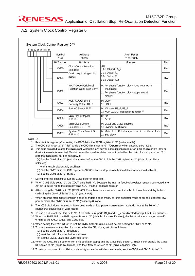
System Clock Control Register 0 (1)
Symbol Address After ResetCM0 0006h 01001000b
Bit Symbol Bit Name Function RW
NOTES :1.2.3.
4.5.
6.
7.
8.
9.10.
11.12.
13.
14. To return from on-chip oscillator mode to high-speed or middle-speed mode, set the CM06 and CM15 bits to “1”.
Rew rite this register after setting the PRC0 bit in the PRCR register to “1” (w rite enable).
CM01 RW
b1 b0
0 0 : I/O port P5_70 1 : Output fC1 0 : Output f81 1 : Output f32
Clock Output FunctionSelect Bit(Valid only in single-chipmode)
CM00 RW
When the CM21 bit is set to “0” (on-chip oscillator stops) and the CM05 bit is set to “1” (main clock stops), the CM06bit is f ixed to “1” (divide-by-8 mode) and the CM15 bit is f ixed to “1” (drive capacity High).
The fC32 clock does not stop. In low -speed mode or low pow er consumption mode, do not set this bit to “1”(peripheral clock stops in w ait mode).
To use the main clock as the clock source for the CPU clock, set bits as follow s. (a) Set the CM05 bit to “0” (oscillate). (b) Wait the main clock oscillation stabilizes. (c) Set the CM11, CM21 and CM07 bits to “0”.
When the PM21 bit in the PM2 register is set to “1” (disable clock modif ication), this bit remains unchanged even ifw riting to the CM02, CM05, and CM07 bits.When setting the PM21 bit to “1”, set the CM07 bit to “0” (main clock) before setting the PM21 bit to “1”.
The CM03 bit is set to “1” (high) w hile the CM04 bit is set to “0” (I/O port) or w hen entering stop mode.This bit is provided to stop the main clock w hen the low pow er consumption mode or on-chip oscillator low pow erdissipation mode is selected. This bit cannot be used for detection as to w hether the main clock stops or not. Tostop the main clock, set bits as follow s: (a) Set the CM07 bit to “1” (sub clock selected) or the CM21 bit in the CM2 register to “1” (On-chip oscillatorselected) w ith the sub-clock stably oscillates. (b) Set the CM20 bit in the CM2 register to “0” (Oscillation stop, re-oscillation detection function disabled). (c) Set the CM05 bit to “1” (Stop).
To use a sub-clock, set this bit to “1”. Also make sure ports P8_6 and P8_7 are directed for input, w ith no pull-ups.
During external clock input, Set the CM05 bit to “0” (oscillate).When CM05 bit is set to “1”, the XOUT pin is held “H”. Because the internal feedback resistor remains connected, theXIN pin is pulled “H” to the same level as XOUT via the feedback resistor.After setting the CM04 bit to “1” (XCIN-XCOUT oscillator function), w ait until the sub-clock oscillates stably beforesw itching the CM07 bit from “0” to “1” (sub-clock).When entering stop mode from high-speed or middle-speed mode, on-chip oscillator mode or on-chip oscillator lowpow er mode, the CM06 bit is set to “1” (divide-by-8 mode).
CM06Main Clock DivisionSelect Bit 0 (7, 13, 14)
0 : CM16 and CM17 enabled1 : Division-by-8 mode RW
CM07System Clock Select Bit(6, 10, 11, 12)
0 : Main clock, PLL clock, or on-chip oscillator clock1 : Sub clock RW
CM05Main Clock Stop Bit(3, 10, 12, 13)
0 : On1 : Off (4, 5) RW
CM04Port XC Select Bit (2) 0 : I/O ports P8_6, P8_7
1 : XCIN-XCOUT oscillation function (9) RW
CM03XCIN-XCOUT DriveCapacity Select Bit (2)
0 : LOW1 : HIGH RW
CM02
WAIT Mode PeripheralFunction Clock Stop Bit (10)
0 : Peripheral function clock does not stop in w ait mode1 : Peripheral function clock stops in w ait mode(8)
RW
b3 b2 b1 b0b7 b6 b5 b4
REJ05B0603-0101/Rev.1.01 June 2005 Page 26 of 29
M16C/62P GroupApplication of Oscillation Stop, Re-Oscillation Detection Function
A.3 System Clock Control Register 1
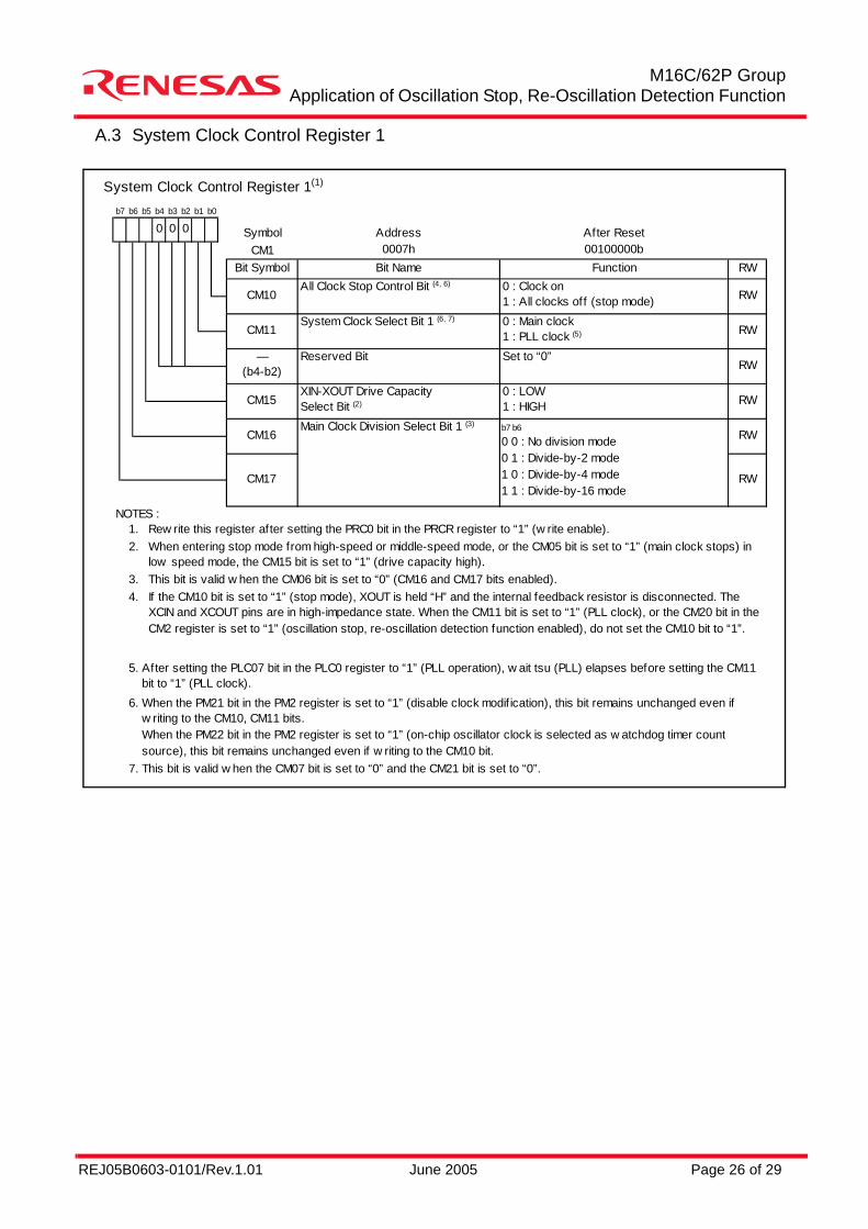
System Clock Control Register 1(1)
Symbol Address After ResetCM1 0007h 00100000b
Bit Symbol Bit Name Function RW
NOTES :1.2.
3.4.
5.
6.
7.
Rew rite this register after setting the PRC0 bit in the PRCR register to “1” (w rite enable).When entering stop mode from high-speed or middle-speed mode, or the CM05 bit is set to “1” (main clock stops) inlow speed mode, the CM15 bit is set to “1” (drive capacity high).This bit is valid w hen the CM06 bit is set to “0” (CM16 and CM17 bits enabled).If the CM10 bit is set to “1” (stop mode), XOUT is held “H” and the internal feedback resistor is disconnected. TheXCIN and XCOUT pins are in high-impedance state. When the CM11 bit is set to “1” (PLL clock), or the CM20 bit in theCM2 register is set to “1” (oscillation stop, re-oscillation detection function enabled), do not set the CM10 bit to “1”.
CM17 RW
b7 b6
0 0 : No division mode0 1 : Divide-by-2 mode1 0 : Divide-by-4 mode1 1 : Divide-by-16 mode
Main Clock Division Select Bit 1 (3)CM16 RW
RW
CM15XIN-XOUT Drive CapacitySelect Bit (2)
0 : LOW1 : HIGH RW
CM10All Clock Stop Control Bit (4, 6) 0 : Clock on
1 : All clocks off (stop mode) RW
0 00b7 b6 b5 b4 b3 b2 b1 b0
After setting the PLC07 bit in the PLC0 register to “1” (PLL operation), w ait tsu (PLL) elapses before setting the CM11bit to “1” (PLL clock).When the PM21 bit in the PM2 register is set to “1” (disable clock modif ication), this bit remains unchanged even ifw riting to the CM10, CM11 bits.When the PM22 bit in the PM2 register is set to “1” (on-chip oscillator clock is selected as w atchdog timer countsource), this bit remains unchanged even if w riting to the CM10 bit.This bit is valid w hen the CM07 bit is set to “0” and the CM21 bit is set to “0”.
CM11System Clock Select Bit 1 (6, 7) 0 : Main clock
1 : PLL clock (5) RW
—(b4-b2)
Reserved Bit Set to “0”
REJ05B0603-0101/Rev.1.01 June 2005 Page 27 of 29
M16C/62P GroupApplication of Oscillation Stop, Re-Oscillation Detection Function
A.4 Oscillation Stop, Re-Oscillation Detection Interrupt Operation (CM27 bit=1)In the sample program, the PLL clock is used as the CPU clock source. In this case, the oscillation stop, re-oscillation detection interrupt operations are shown below:(1) When the main clock stops with the following states.
• The oscillation stop, re-oscillation detection interrupt request are generated.• The CM22 bit is set to “1”. (The main clock stop is detected.)• The CM23 bit is set to “1”. (The main clock stops.)• The CM21 bit remains unchanged.NOTES : When using the PLL clock as the CPU clock source, the CM21 bit remains unchanged even if the
main clock stops. Set the CM21 bit to “1” (on-chip oscillator clock (on-chip oscillator on)) in the interrupt routine.
(2) When the main clock re-oscillates from the state that the main clock stops with the following states.• The oscillation stop, re-oscillation detection interrupt request are generated.• The CM22 bit is set to “1”. (The main clock stop is detected.)• The CM23 bit is set to “0”. (The main clock oscillates.)• The CM21 bit remains unchanged.
A.5 How to Use Oscillation Stop, Re-Oscillation Detection Function• The oscillation stop, re-oscillation detection interrupt use both of the watchdog timer interrupt and vector.
When using both the oscillation stop, re-oscillation detection interrupt and the watchdog timer interrupt, read the CM22 bit (oscillation stop, re-oscillation detection flag) in the interrupt routine and determine the interrupt request by which interrupt factor of the oscillation stop, re-oscillation detection interrupt or the watchdog timer interrupt.
• When the main clock re-oscillates after the oscillation stops, set the main clock back to the clock source of the CPU clock or peripheral functions by a program.
• The CM22 bit is set to “1” at the same time as the oscillation stop, re-oscillation detection interrupt generation.When the CM22 bit is se to “1”, the oscillation stop, re-oscillation detection interrupt is disabled.When setting the CM22 bit to “0” by a program, the oscillation stop, re-oscillation detection interrupt is enabled.
• When the CM20 bit is set to “1” and the main clock stops in low-speed mode, the oscillation stop, re-oscillation detection interrupt request is generated. At the same time, the on-chip oscillator starts oscillating. At this time, the sub clock remains as the clock source for the CPU clock. However, the on-chip oscillator clock is selected as the clock source for the peripheral function clock.
• When entering wait mode while the oscillation stop, re-oscillation detection function is used, set the CM02 bit to “0” (the peripheral function clock does not stop in wait mode).
• The oscillation stop, re-oscillation detection function is to provide for the main clock stop by the external factors. When stopping or oscillating the main clock by a program, in other words, when setting to stop mode or changing the CM05 bit, set the CM20 bit to “0” (oscillation stop, re-oscillation detection function disabled).
• When the main clock frequency is 2MHz or less, this function cannot be used. Set the CM20 bit to “0”.

REJ05B0603-0101/Rev.1.01 June 2005 Page 28 of 29
M16C/62P GroupApplication of Oscillation Stop, Re-Oscillation Detection Function
REVISION HISTORYM16C/62P Group
Application of Oscillation Stop, Re-Oscillation Detection Function
Rev. DateDescription
Page Summary1.01 June 23, 2005 − First Edition issued
REJ05B0603-0101/Rev.1.01 June 2005 Page 29 of 29
M16C/62P GroupApplication of Oscillation Stop, Re-Oscillation Detection Function
Keep safety first in your circuit designs!
Notes regarding these materials
1. Renesas Technology Corporation puts the maximum effort into making semiconductor prod-ucts better and more reliable, but there is always the possibility that trouble may occur withthem. Trouble with semiconductors may lead to personal injury, fire or property damage.Remember to give due consideration to safety when making your circuit designs, with ap-propriate measures such as (i) placement of substitutive, auxiliary circuits, (ii) use of non-flammable material or (iii) prevention against any malfunction or mishap.
1. These materials are intended as a reference to assist our customers in the selection of theRenesas Technology Corporation product best suited to the customer's application; they donot convey any license under any intellectual property rights, or any other rights, belongingto Renesas Technology Corporation or a third party.
2. Renesas Technology Corporation assumes no responsibility for any damage, or infringe-ment of any third-party's rights, originating in the use of any product data, diagrams, charts,programs, algorithms, or circuit application examples contained in these materials.
3. All information contained in these materials, including product data, diagrams, charts, pro-grams and algorithms represents information on products at the time of publication of thesematerials, and are subject to change by Renesas Technology Corporation without noticedue to product improvements or other reasons. It is therefore recommended that custom-ers contact Renesas Technology Corporation or an authorized Renesas Technology Cor-poration product distributor for the latest product information before purchasing a productlisted herein.The information described here may contain technical inaccuracies or typographical errors.Renesas Technology Corporation assumes no responsibility for any damage, liability, orother loss rising from these inaccuracies or errors.Please also pay attention to information published by Renesas Technology Corporation byvarious means, including the Renesas Technology Corporation Semiconductor home page(http://www.renesas.com).
4. When using any or all of the information contained in these materials, including productdata, diagrams, charts, programs, and algorithms, please be sure to evaluate all informa-tion as a total system before making a final decision on the applicability of the informationand products. Renesas Technology Corporation assumes no responsibility for any dam-age, liability or other loss resulting from the information contained herein.
5. Renesas Technology Corporation semiconductors are not designed or manufactured foruse in a device or system that is used under circumstances in which human life is poten-tially at stake. Please contact Renesas Technology Corporation or an authorized RenesasTechnology Corporation product distributor when considering the use of a product con-tained herein for any specific purposes, such as apparatus or systems for transportation,vehicular, medical, aerospace, nuclear, or undersea repeater use.
6. The prior written approval of Renesas Technology Corporation is necessary to reprint orreproduce in whole or in part these materials.
7. If these products or technologies are subject to the Japanese export control restrictions,they must be exported under a license from the Japanese government and cannot be im-ported into a country other than the approved destination.Any diversion or reexport contrary to the export control laws and regulations of Japan and/or the country of destination is prohibited.
8. Please contact Renesas Technology Corporation for further details on these materials orthe products contained therein.