application description 03/2015 communication via the cm ... · freeport is a freely programmable,...
TRANSCRIPT

https://support.industry.siemens.com/cs/ww/en/109474684
Application description 03/2015
Communication via the CM PtP of the ET200 SP using the Freeport Protocol S7-300, ET200SP, CM PtP, SIMATIC MV340

Warranty and liability
Connecting MV340 to a CM PtP Entry-ID: 109474684, Version 1.0, 03/2015 2
S
iem
ens
AG 2
013
All r
ight
s re
serv
ed
Warranty and liability
Note The Application Examples are not binding and do not claim to be complete regarding the circuits shown, equipping and any eventuality. The Application Examples do not represent customer-specific solutions. They are only intended to provide support for typical applications. You are responsible for ensuring that the described products are used correctly. These application examples do not relieve you of the responsibility to use safe practices in application, installation, operation and maintenance. When using these Application Examples, you recognize that we cannot be made liable for any damage/claims beyond the liability clause described. We reserve the right to make changes to these Application Examples at any time without prior notice. If there are any deviations between the recommendations provided in these application examples and other Siemens publications – e.g. Catalogs – the contents of the other documents have priority.
We do not accept any liability for the information contained in this document.
Any claims against us – based on whatever legal reason – resulting from the use of the examples, information, programs, engineering and performance data etc., described in this Application Example shall be excluded. Such an exclusion shall not apply in the case of mandatory liability, e.g. under the German Product Liability Act (“Produkthaftungsgesetz”), in case of intent, gross negligence, or injury of life, body or health, guarantee for the quality of a product, fraudulent concealment of a deficiency or breach of a condition which goes to the root of the contract (“wesentliche Vertragspflichten”). The damages for a breach of a substantial contractual obligation are, however, limited to the foreseeable damage, typical for the type of contract, except in the event of intent or gross negligence or injury to life, body or health. The above provisions do not imply a change of the burden of proof to your detriment. Any form of duplication or distribution of these Application Examples or excerpts hereof is prohibited without the expressed consent of the Siemens AG.
Security informa-tion
Siemens provides products and solutions with industrial security functions that support the secure operation of plants, solutions, machines, equipment and/or networks. They are important components in a holistic industrial security concept. With this in mind, Siemens’ products and solutions undergo continuous development. Siemens recommends strongly that you regularly check for product updates.
For the secure operation of Siemens products and solutions, it is necessary to take suitable preventive action (e.g. cell protection concept) and integrate each component into a holistic, state-of-the-art industrial security concept. Third-party products that may be in use should also be considered. For more information about industrial security, visit http://www.siemens.com/industrialsecurity.
To stay informed about product updates as they occur, sign up for a product-specific newsletter. For more information, visit http://support.industry.siemens.com.
Table of contents
Connecting MV340 to a CM PtP Entry-ID: 109474684, Version 1.0, 03/2015 3
S
iem
ens
AG 2
013
All r
ight
s re
serv
ed
Table of contents Warranty and liability ................................................................................................... 2
1 Task ..................................................................................................................... 4 2 Solution............................................................................................................... 5
2.1 Solution overview ................................................................................. 5 2.2 Hardware and software components used........................................... 6
3 Description of the Freeport Protocol ............................................................... 8
3.1 Introduction ........................................................................................... 8 3.2 Configuring the interface ...................................................................... 9
4 Description of the STEP7 Program ................................................................ 11
4.1 Overview............................................................................................. 11 4.2 Operation of the FB PtP_Freeport (FB770) ....................................... 13 4.2.1 Sequence and call of the FB PtP_Freeport (FB770) ......................... 13 4.2.2 “Startup” state ..................................................................................... 15 4.2.3 “Configuration” (Port_Config) state .................................................... 16 4.2.4 “Reset receive buffer” (Receive_Reset) state .................................... 18 4.2.5 “Receive data” (Receive_P2P) state .................................................. 19
5 Configuring the Communication Parameters via TIA Portal ....................... 21
6 Starting Up the Application ............................................................................ 24
6.1 Configuration of the hardware ............................................................ 24 6.2 Configuring the hardware ................................................................... 26 6.3 Opening and loading of the STEP 7 project ....................................... 28 6.4 Operating the Application ................................................................... 29
7 Differences of the User Programs of S7-300 and S7-1500 .......................... 31
8 Related literature ............................................................................................. 33
9 History............................................................................................................... 33

1 Task 2.1 Solution overview
Connecting MV340 to a CM PtP Entry-ID: 109474684, Version 1.0, 03/2015 4
Cop
yrig
ht
Sie
men
s AG
201
3 Al
l rig
hts
rese
rved
1 Task Introduction
This application shows you how to use the serial interface of the ET 200SP as distributed I/O of a SIMATIC S7-300 station. As an example, the data of a handheld scanner is received via the communication interface of the automation system and stored in the controller.
Overview of the automation task The following figure gives an overview of the automation task: Figure 1-1
Readingdevice
Data carrier
S7-300 Automation system
Communica-tion interface
S7-300Controller:
configuration, data storage
RS232
Description of the automation task This application is to cover the following requirements: • The application demonstrates the handling of the CM PtP of the ET 200SP on
a concrete application. • The information of a code (e.g. data matrix code) should be transferred by a
handheld reader via the serial interface of a SIMATIC S7-300 controller. • The data is to be temporarily stored for further processing.

2 Solution 2.1 Solution overview
Connecting MV340 to a CM PtP Entry-ID: 109474684, Version 1.0, 03/2015 5
Cop
yrig
ht
Sie
men
s AG
201
3 Al
l rig
hts
rese
rved
2 Solution 2.1 Solution overview
Objective of this application This application shows you how to do the following in a S7-300 system • configuring the serial interface of the CM (communication module) PtP of the
ET 200SP for Freeport. The configuration is performed via the hardware configuration as well as via instructions.
• programming data receipt from the SIMATIC MV340 handheld reader. The precise functionality of the program is described in chapter 4.
Schematic layout The following figure gives a schematic overview of the most important components of the solution: Figure 2-1
STEP7 V12
Engineering station
MV340
RS232
CM PtPET 200SP
Core topics of this application The following core points are discussed in this application: • Basics on Freeport(ASCII) protocol • Configuring the hardware environment • Configuring the PtP (Point to Point) interface • Programming the data receipt

2 Solution 2.2 Hardware and software components used
Connecting MV340 to a CM PtP Entry-ID: 109474684, Version 1.0, 03/2015 6
Cop
yrig
ht
Sie
men
s AG
201
3 Al
l rig
hts
rese
rved
Advantages of this solution This application offers you the following advantages: • conveying general information about the Freeport protocol. • Demonstrating the use of the serial interface of an ET 200SP as distributed I/O
of a SIMATIC S7-300 station. • adjustable sample project for fast creation of own projects.
Valid until • Software versions from TIA Portal V12 • SIMATIC S7-300 and S7-400 CPUs • ET 200SP with CM PtP
Topics not covered by this application This application does not contain • a description for operating the MV340. An operating instruction can be found in
the manual to the device (see \3\). • Introduction to the issue of SCL programming • Basics on TIA Portal Basic knowledge of these topics is assumed.
2.2 Hardware and software components used
This application was generated with the following components:
Hardware components Table 2-1
Component Qty. Ordering number Note
PM 70W 120/230 AVC 1 6EP1332-4BA00 CPU315-2 PN/DP 1 6ES7315-2EH14-0AB0 Other PROFINET-
capable CPUs from the S7-300 and the S7-400 spectrum can also be used
ET 200SP IM155-6PN ST
1 6ES7155-6AU00-0BN0
CM PtP 1 6ES7137-6AA00-0BA0 Base Unit 1 6ES7193-6BP00-0xA0 Server module 1 6ES7193-6PA00-0AA0 SIMATIC MV340 1 6GF3340-0HT01
Note If you are using a different hardware than the one in the sample project, you have to perform the respective changes in the hardware configuration!

2 Solution 2.2 Hardware and software components used
Connecting MV340 to a CM PtP Entry-ID: 109474684, Version 1.0, 03/2015 7
Cop
yrig
ht
Sie
men
s AG
201
3 Al
l rig
hts
rese
rved
Standard software components Table 2-2
Component Qty. Ordering number Note
TIA Portal V12 1 6ES7822-1AE02-0YA5
Example files and projects The following list includes all files and projects used in this example. Table 2-3
Component Note
109474684_S7-300_CM_PtP_MV340_DOKU_V1d0_en.pdf
Application Description
109474684_S7-300_CM_PtP_MV340_CODE_V1d0.zip This zip file contains the STEP 7 V12 (TIA) project.
In the chapter Literature you can find helpful links on the issue. On the HTML page of the application you can furthermore find a project to connect the handheld reader MV340 to a S7-1500 station.

3 Description of the Freeport Protocol 3.1 Introduction
Connecting MV340 to a CM PtP Entry-ID: 109474684, Version 1.0, 03/2015 8
Cop
yrig
ht
Sie
men
s AG
201
3 Al
l rig
hts
rese
rved
3 Description of the Freeport Protocol
3.1 Introduction
Basics Freeport is a freely programmable, telegram-based protocol which is also known as ASCII protocol. It controls the data transmission for a point-to-point connection between the communication module and a communication partner. The Freeport protocol only includes the bit transmission layer (layer 1). You can set different parameters for the protocol. You have to specify a large amount of the parameters separately for the send and for the receive direction.
Parameter The following parameters for the connection can be set for the sending of data via the Freeport protocol: • Data transmission rate (in baud) • Bits per character • Parity • Stop bits • Flow control • Operating mode
The parameters below can be set separately, for the receive and the send direction each: • Break before telegram start • Specifying a send break (“idle line”) • Specifying the start of the message (preamble) • Specifying the end of the message (postamble) • Character delay time According to the settings, the CM will recognize the start and the end of a telegram. An extensive list with a description of the parameters of the Freeport protocol can be found in the “Configurations for Point-to-Point Connections” manual (see \4\)

3 Description of the Freeport Protocol 3.2 Configuring the interface
Connecting MV340 to a CM PtP Entry-ID: 109474684, Version 1.0, 03/2015 9
Cop
yrig
ht
Sie
men
s AG
201
3 Al
l rig
hts
rese
rved
3.2 Configuring the interface
Configuration via TIA Portal V12 The parameters for the Freeport communication can be set in the “Properties” of the inspector window of the CM PtP. Figure 3-1
Make sure that the communication partner of the CM PtP (in this application example the handheld reader MV340) is suitably configured to your settings.
Configuration via instructions from the user program Additionally or alternatively to the settings in the hardware configuration (see Figure 3-1) the following three instructions are provided. These instructions overwrite the settings of the hardware configuration. • Port_Config
You can change the RS232 port parameters, such as, for example, the data transmission rate in running operation with the Port_Config (port configuration) instruction from the user program.
• Receive_Config You can change the serial receive parameters in running operation with the Receive_Config (receive configuration) instruction. This instruction configures the conditions that identify the start and the end of the received data.
• Send_Config You can change the serial transmission parameters in the user program in running operation with the Send_Config (send configuration) instruction. This instruction configures the start and end identifier that are sent with a telegram.

3 Description of the Freeport Protocol 3.2 Configuring the interface
Connecting MV340 to a CM PtP Entry-ID: 109474684, Version 1.0, 03/2015 10
Cop
yrig
ht
Sie
men
s AG
201
3 Al
l rig
hts
rese
rved
Communication via the Freeport instructions In order to receive or send data from a serial terminal device, use the following instructions: • Receive_P2P
The Receive_P2P instruction (receiving data via a point-to-point connection) checks the telegrams that have been received in the CM. If a telegram is available, it is transferred from the CM to the CPU.
• Send_P2P The Send_P2P instruction (sending point-to-point data) starts the transmission of data and transfers the content of the assigned buffer to the communication module.
If your serial terminal device uses secondary signals, you can set them and read them out with the following instructions, provided automatic operation is not configured: • Signal_Set • Signal_Get

4 Description of the STEP7 Program 4.1 Overview
Connecting MV340 to a CM PtP Entry-ID: 109474684, Version 1.0, 03/2015 11
Cop
yrig
ht
Sie
men
s AG
201
3 Al
l rig
hts
rese
rved
4 Description of the STEP7 Program
4.1 Overview
Functions The S7 program realizes the following functions: • Initializing parameters used • Configuring point-to-point connection of the CM PtP (Port_Config) • Deleting the receive buffer of the CM PtP (Receive_Reset) • Receiving the data of the MV340 from the CM PtP (Receive_P2P) and storage
in a ring buffer
The functions are encapsulated in the FB PtP_Freeport (FB770) and are successively processed in a sequencer (compare chapter 4.2).
Schematic layout The following graphic shows the program structure of the STEP7 project. Figure 4-1

4 Description of the STEP7 Program 4.1 Overview
Connecting MV340 to a CM PtP Entry-ID: 109474684, Version 1.0, 03/2015 12
Cop
yrig
ht
Sie
men
s AG
201
3 Al
l rig
hts
rese
rved
Blocks and instructions The following blocks and instructions are used in the STEP7 project: Table 4-1
Element Symbolic name Description/classification
OB1 Main Calls the FB PtP_Freeport and transmits the start address of the CM. You have to adjust this call, if you have a different start address in your configuration.
Pro
gram
cal
l
OB100 Startup Sets the communication parameters in DB Port_Config_Settings when restarting the program.
FB770 PtP_Freeport The FB PtP_Freeport encapsulates the instructions Port_Config, Receive_Reset and Receive_P2P.
In-h
ouse
dev
elop
men
t
DB770 PtP_Freeport_DB Instance DB of FB PtP_Freeport DB771 Port_Config_Settings Includes the communication parameter for
Port_Config. You can perform changes of the communication settings via a change of the start parameters (see chapter 5).
DB772 buffer_ptp Includes the ring buffer of the program. This is where the data from the receive buffer is stored in order to be able to keep them for longer.
Instruction: FB610
Port_Config Configuration of the serial interface of the CM PtP.
Sys
tem
blo
cks
Instruction: FB617
Receive_Reset Delete receive buffer of the CM PtP.
Instruction: FB614
Receive_P2P Store data from the CM PtP in receive buffer of the CPU.
4 Description of the STEP7 Program 4.2 Operation of the FB PtP_Freeport (FB770)
Connecting MV340 to a CM PtP Entry-ID: 109474684, Version 1.0, 03/2015 13
Cop
yrig
ht
Sie
men
s AG
201
3 Al
l rig
hts
rese
rved
4.2 Operation of the FB PtP_Freeport (FB770)
4.2.1 Sequence and call of the FB PtP_Freeport (FB770)
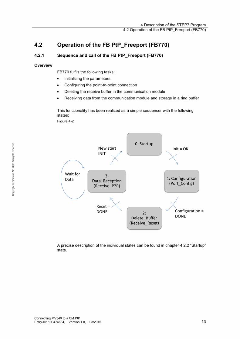
Overview FB770 fulfils the following tasks: • Initializing the parameters • Configuring the point-to-point connection • Deleting the receive buffer in the communication module • Receiving data from the communication module and storage in a ring buffer This functionality has been realized as a simple sequencer with the following states: Figure 4-2
New startINIT
Wait forData
Init = OK
Configuration = DONE
Reset = DONE
A precise description of the individual states can be found in chapter 4.2.2 “Startup” state.

4 Description of the STEP7 Program 4.2 Operation of the FB PtP_Freeport (FB770)
Connecting MV340 to a CM PtP Entry-ID: 109474684, Version 1.0, 03/2015 14
Cop
yrig
ht
Sie
men
s AG
201
3 Al
l rig
hts
rese
rved
Call and parameters The figure shows the call interface of FB PtP_Freeport (FB770). The parameters are described in Table 4-2. Figure 4-3
Table 4-2
Parameter Type Note
PORT IN UInt
The value of the “Port” IN parameter is the start address of the CM. The I/O addresses are in the properties of the CM, whereby the start address is used as input value for the “Port” parameter.
INIT IN
Bool If the edge is positive, the “Startup” state is introduced.
DONE OUT Bool
If new data is stored in the ring buffer, DONE =TRUE is the case for one cycle.
ERROR OUT Bool
If an error is pending in the block, ERROR=TRUE is set.
4 Description of the STEP7 Program 4.2 Operation of the FB PtP_Freeport (FB770)
Connecting MV340 to a CM PtP Entry-ID: 109474684, Version 1.0, 03/2015 15
Cop
yrig
ht
Sie
men
s AG
201
3 Al
l rig
hts
rese
rved
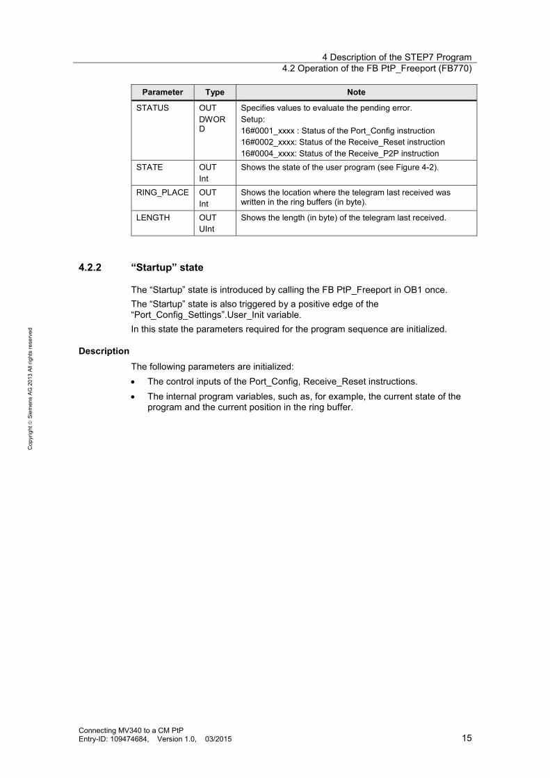
Parameter Type Note
STATUS OUT DWORD
Specifies values to evaluate the pending error. Setup: 16#0001_xxxx : Status of the Port_Config instruction 16#0002_xxxx: Status of the Receive_Reset instruction 16#0004_xxxx: Status of the Receive_P2P instruction
STATE OUT Int
Shows the state of the user program (see Figure 4-2).
RING_PLACE OUT Int
Shows the location where the telegram last received was written in the ring buffers (in byte).
LENGTH OUT UInt
Shows the length (in byte) of the telegram last received.
4.2.2 “Startup” state
The “Startup” state is introduced by calling the FB PtP_Freeport in OB1 once. The “Startup” state is also triggered by a positive edge of the “Port_Config_Settings”.User_Init variable. In this state the parameters required for the program sequence are initialized.
Description The following parameters are initialized: • The control inputs of the Port_Config, Receive_Reset instructions. • The internal program variables, such as, for example, the current state of the
program and the current position in the ring buffer.

4 Description of the STEP7 Program 4.2 Operation of the FB PtP_Freeport (FB770)
Connecting MV340 to a CM PtP Entry-ID: 109474684, Version 1.0, 03/2015 16
Cop
yrig
ht
Sie
men
s AG
201
3 Al
l rig
hts
rese
rved
4.2.3 “Configuration” (Port_Config) state
Overview The FB770 is in the “Configuration” state due to the initialization in “Startup” state and the setting of the internal "PtP_Freeport_DB".navi.state = "Configuration" variable. In this state the Port_Config instruction for setting the communication parameters of the point-to-point connection is called.
Note The call of Port_Config is optional and overwrites the settings of the hardware configuration. If you want to change your communication settings dynamically, use the Port_Config instruction for this purpose.
Program code Figure 4-4
4
5.
3.
1.
2.
1.
4 Description of the STEP7 Program 4.2 Operation of the FB PtP_Freeport (FB770)
Connecting MV340 to a CM PtP Entry-ID: 109474684, Version 1.0, 03/2015 17
Cop
yrig
ht
Sie
men
s AG
201
3 Al
l rig
hts
rese
rved
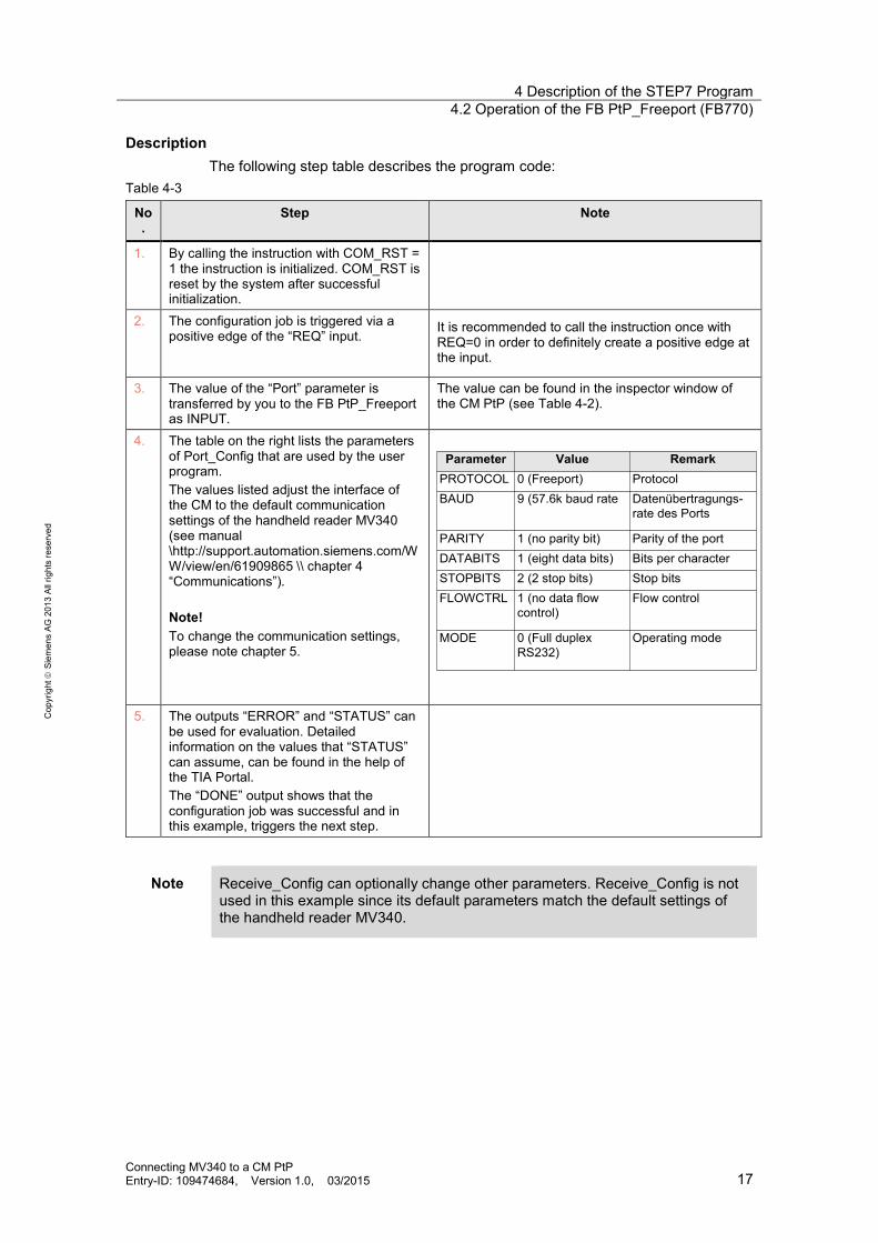
Description The following step table describes the program code:
Table 4-3
No.
Step Note
1. By calling the instruction with COM_RST = 1 the instruction is initialized. COM_RST is reset by the system after successful initialization.
2. The configuration job is triggered via a positive edge of the “REQ” input.
It is recommended to call the instruction once with REQ=0 in order to definitely create a positive edge at the input.
3. The value of the “Port” parameter is transferred by you to the FB PtP_Freeport as INPUT.
The value can be found in the inspector window of the CM PtP (see Table 4-2).
4. The table on the right lists the parameters of Port_Config that are used by the user program. The values listed adjust the interface of the CM to the default communication settings of the handheld reader MV340 (see manual \http://support.automation.siemens.com/WW/view/en/61909865 \\ chapter 4 “Communications”). Note! To change the communication settings, please note chapter 5.
Parameter Value Remark
PROTOCOL 0 (Freeport) ProtocolBAUD 9 (57.6k baud rate Datenübertragungs-
rate des Ports
PARITY 1 (no parity bit) Parity of the portDATABITS 1 (eight data bits) Bits per characterSTOPBITS 2 (2 stop bits) Stop bitsFLOWCTRL 1 (no data flow
control)Flow control
MODE 0 (Full duplexRS232)
Operating mode
5. The outputs “ERROR” and “STATUS” can
be used for evaluation. Detailed information on the values that “STATUS” can assume, can be found in the help of the TIA Portal. The “DONE” output shows that the configuration job was successful and in this example, triggers the next step.
Note Receive_Config can optionally change other parameters. Receive_Config is not used in this example since its default parameters match the default settings of the handheld reader MV340.

4 Description of the STEP7 Program 4.2 Operation of the FB PtP_Freeport (FB770)
Connecting MV340 to a CM PtP Entry-ID: 109474684, Version 1.0, 03/2015 18
Cop
yrig
ht
Sie
men
s AG
201
3 Al
l rig
hts
rese
rved
4.2.4 “Reset receive buffer” (Receive_Reset) state
Overview If the “DONE” output of Port_Config shows that the configuration job has been completed, the “reset receive buffer” state is triggered. The receive buffer is reset, in the event that there is already data in the receive buffer of the CM PtP.
Program code Figure 4-5
4.
2.3.
1.
Description The following step table describes the program code: Table 4-4
No. Step Note
1. By calling the instruction with COM_RST = 1 the instruction is initialized. COM_RST is reset by the system after successful initialization.
2. The “REQ” input triggers the deleting of the receive buffer in the CM PtP through a positive edge.
It is recommended to call the instruction once with REQ=0 in order to definitely create a positive edge at the input
3. You transfer the value of the “Port” parameter to the FB PtP_Freeport as INPUT.
The value can be found in the inspector window of the CM PtP (see Table 4-2).
4. The “DONE” output shows that the resetting was successful and in this example, triggers the next step.

4 Description of the STEP7 Program 4.2 Operation of the FB PtP_Freeport (FB770)
Connecting MV340 to a CM PtP Entry-ID: 109474684, Version 1.0, 03/2015 19
Cop
yrig
ht
Sie
men
s AG
201
3 Al
l rig
hts
rese
rved
4.2.5 “Receive data” (Receive_P2P) state
Overview FB770 goes to the “Receive data” state once the receive buffer of the communication module was deleted. As a result, the initialization steps are ended and the “Receive data” state is processed cyclically. The “Receive data” state is split the following way: • Waiting for data from the CM PtP (Receive_P2P) • Picking up data from the CM (Receive_P2P) • Storing data in the ring buffer
“Picking up of data” program code Figure 4-6
3.4.
1.
2.
Description of “Picking up of data” The following step table describes the program code: Table 4-5
No. Step Note
5. By calling the instruction with COM_RST = 1 the instruction is initialized. COM_RST is reset by the system after successful initialization.
6. The value of the “Port” parameter is transferred by you to the FB PtP_Freeport as INPUT. The value can be found in the inspector window of the CM PtP (see Table 4-2).
7. As soon as data from the serial terminal device has been received in the CM, the instruction will write this data in the BUFFER input of the 256 byte array. From this receive buffer the data is saved in the ring buffer once it has been successfully transferred.
Note! The CM PtP RS232 HF can receive telegrams of a length of up to 4kByte.

4 Description of the STEP7 Program 4.2 Operation of the FB PtP_Freeport (FB770)
Connecting MV340 to a CM PtP Entry-ID: 109474684, Version 1.0, 03/2015 20
Cop
yrig
ht
Sie
men
s AG
201
3 Al
l rig
hts
rese
rved
No. Step Note
8. The outputs “ERROR” and “STATUS” can be used for evaluation. Detailed information on the values that “STATUS” can assume, can be found in the help of the TIA Portal. In the event that the array is too small for the received data (ERROR = 1 and STATUS = 0x8088), the program will go to the “Reset receive buffer” state.
Program code “Storing of data“ Figure 4-7
2.
3.
1.
.
.
Description of “Storing of data“ The following step table describes the program code:
No. Step Note
9. NDR=TRUE shows that data has been written in the “Recv_Buffer” receive buffer.
10. The program writes the number of bytes that are displayed on the LENGTH output from the receive buffer to the ring buffer. The new data is stored in the ring buffer directly after the data last received.
DB2 buffer_ptp has been created for the ring buffer that can accommodate a data volume of 1024 byte.
11. The end identifier „; „ that consists of two bytes, is attached to the received telegram and a possibly overwritten old telegram is overwritten with blanks.
Note! Your telegram last received starts in the DB buffer_ptp with “RING_PLACE” offset and ends with „; „ or after the number of “LENGTH” bytes.

5 Configuring the Communication Parameters via TIA Portal
Connecting MV340 to a CM PtP Entry-ID: 109474684, Version 1.0, 03/2015 21
Cop
yrig
ht
Sie
men
s AG
201
3 Al
l rig
hts
rese
rved
5 Configuring the Communication Parameters via TIA Portal
Requirement You have to adjust the communication settings of the CM PtP if one of the following conditions is fulfilled: • You are not using the default settings of the handheld reader SIMATIC MV340 • You are using a different distributed I/O device which has different
communication settings than the default settings of the MV340. You have three options for setting the parameters: • Changing the parameter of the DB Port_Config_Settings (DB771) in the start
OB (OB100). • Adjusting and inserting the respective instructions in FB770. • Changing the hardware configuration.
Configuring whilst using the DB Port_Config_Settings If you would like to change the settings of the serial interface via the DB Port_Config_Settings, proceed as follows:
Table 5-1
No. Procedure Note
12. Adjust the start values of the DB Port_Config_Settings in OB100 to your requirements. For the meaning of the individual values, use the help function of the TIA Portal. (help for Port_Config instruction)
13. Compile your project and load it into the
CPU.
Adjusting and inserting instructions Three instructions are available to you to adjust the communication settings via the user program. Port_Config is already used in the user program: • Port_Config:
Changing of parameters such as data transmission rate via the user program in running operation. For this purpose, compare the previous section with the instruction on how to directly change parameters in the sample project via the DB Port_Config_Settings.

5 Configuring the Communication Parameters via TIA Portal
Connecting MV340 to a CM PtP Entry-ID: 109474684, Version 1.0, 03/2015 22
Cop
yrig
ht
Sie
men
s AG
201
3 Al
l rig
hts
rese
rved
If you want to change other parameters, you can insert the following instructions: • Send_Config
Changing the serial transmission parameters via your program. This instruction configures the conditions that indicate the start and the end of the data to be sent.
• Receive_Config: Changing the serial receive parameter via your program in running operation. This instruction configures the conditions that identify the start and the end of the received data.
For further information, please read the function manual (see \http://support.automation.siemens.com/WW/view/en/59057093 \) or the help of the TIA Portal V12.
Adjusting in the hardware configuration Table 5-2 shows the configuration of the CM PtP for the default communication settings of the MV340. You have to adjust these settings individually to your serial terminal device.
Table 5-2
No. Instruction Note
14. Open the STEP7 V12 project. Go to the “Device view” tab. This is where you select your CM PtP and then go to the property tab in the inspector window
15. Navigate to the port configuration and make the desired settings.

5 Configuring the Communication Parameters via TIA Portal
Connecting MV340 to a CM PtP Entry-ID: 109474684, Version 1.0, 03/2015 23
Cop
yrig
ht
Sie
men
s AG
201
3 Al
l rig
hts
rese
rved
No. Instruction Note
16. Via the configuration of message sending/receiving, you can adjust parameters such as message start, breaks and idle lines.
17. Delete the “Port_Config”
instruction from your user program and add the instruction on the right to the “Configuration” step.
18. Save your program and load the hardware configuration in your CPU.
NOTICE If you are calling the blocks Port_Config, Send_Config or Receive_Config in your user program, they will overwrite the settings made there.
6 Starting Up the Application
Connecting MV340 to a CM PtP Entry-ID: 109474684, Version 1.0, 03/2015 24
Cop
yrig
ht
Sie
men
s AG
201
3 Al
l rig
hts
rese
rved
6 Starting Up the Application
6.1 Configuration of the hardware
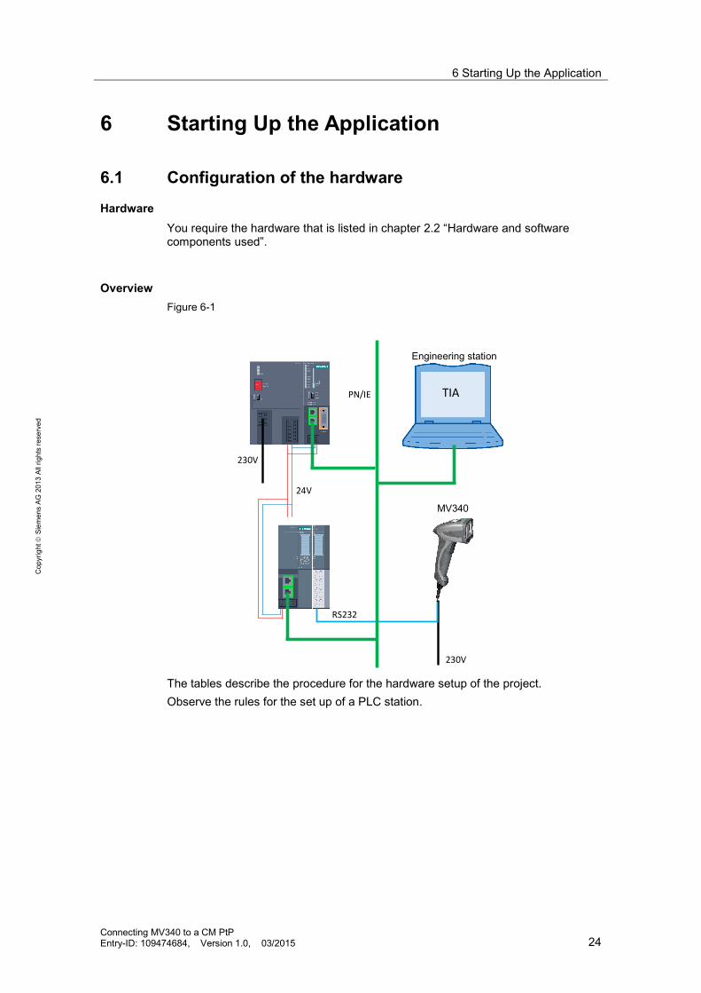
Hardware You require the hardware that is listed in chapter 2.2 “Hardware and software components used”.
Overview Figure 6-1
RS232
TIA
Engineering station
MV340
230V
230V
24V
PN/IE
The tables describe the procedure for the hardware setup of the project. Observe the rules for the set up of a PLC station.
6 Starting Up the Application
Connecting MV340 to a CM PtP Entry-ID: 109474684, Version 1.0, 03/2015 25
Cop
yrig
ht
Sie
men
s AG
201
3 Al
l rig
hts
rese
rved
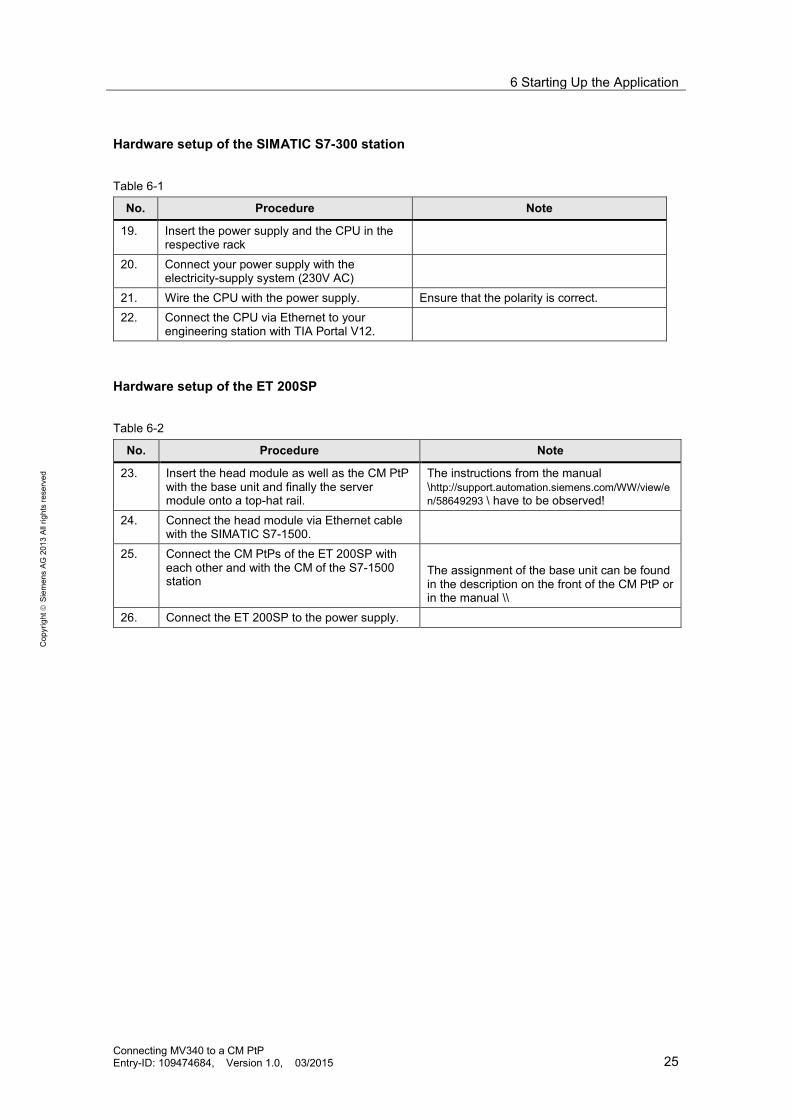
Hardware setup of the SIMATIC S7-300 station Table 6-1
No. Procedure Note
19. Insert the power supply and the CPU in the respective rack
20. Connect your power supply with the electricity-supply system (230V AC)
21. Wire the CPU with the power supply. Ensure that the polarity is correct. 22. Connect the CPU via Ethernet to your
engineering station with TIA Portal V12.
Hardware setup of the ET 200SP Table 6-2
No. Procedure Note
23. Insert the head module as well as the CM PtP with the base unit and finally the server module onto a top-hat rail.
The instructions from the manual \http://support.automation.siemens.com/WW/view/en/58649293 \ have to be observed!
24. Connect the head module via Ethernet cable with the SIMATIC S7-1500.
25. Connect the CM PtPs of the ET 200SP with each other and with the CM of the S7-1500 station
The assignment of the base unit can be found in the description on the front of the CM PtP or in the manual \\
26. Connect the ET 200SP to the power supply.

6 Starting Up the Application
Connecting MV340 to a CM PtP Entry-ID: 109474684, Version 1.0, 03/2015 26
Cop
yrig
ht
Sie
men
s AG
201
3 Al
l rig
hts
rese
rved
6.2 Configuring the hardware
Configuring the SIMATIC S7-300 Table 6-3
No. Procedure Note
27. Open the TIA Portal V12 in the project view. Search for “Accessible devices”. For this purpose navigate to “Project Tree > Online Access> [Your_Ethernet_Adapter]> Update accessible devices” Your SIMATIC S7 station is now recognized.
28. Navigate to “[Your_S7_Station] > Online &
diagnostics” In the graphic area of “Online & diagnostics” now select "Functions > Assign IP address"
2.
1.1.
2.
29. Enter the following IP address and subnet
mask in the input fields: 192.168.0.2. 255.255.255.0 Confirm the action with "Assign IP address" The S7-300 station is now assigned the IP address of your engineering station.
1.
2.
1.
2.
6 Starting Up the Application
Connecting MV340 to a CM PtP Entry-ID: 109474684, Version 1.0, 03/2015 27
Cop
yrig
ht
Sie
men
s AG
201
3 Al
l rig
hts
rese
rved
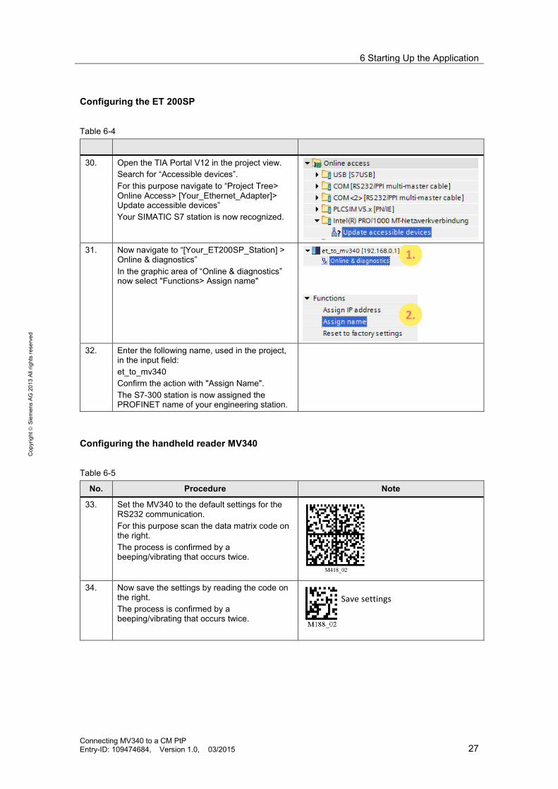
Configuring the ET 200SP
Table 6-4
30. Open the TIA Portal V12 in the project view. Search for “Accessible devices”. For this purpose navigate to “Project Tree> Online Access> [Your_Ethernet_Adapter]> Update accessible devices” Your SIMATIC S7 station is now recognized.
31. Now navigate to “[Your_ET200SP_Station] >
Online & diagnostics” In the graphic area of “Online & diagnostics” now select "Functions> Assign name"
2.
1.1.
2.
32. Enter the following name, used in the project,
in the input field: et_to_mv340 Confirm the action with "Assign Name". The S7-300 station is now assigned the PROFINET name of your engineering station.
Configuring the handheld reader MV340
Table 6-5
No. Procedure Note
33. Set the MV340 to the default settings for the RS232 communication. For this purpose scan the data matrix code on the right. The process is confirmed by a beeping/vibrating that occurs twice.
34. Now save the settings by reading the code on
the right. The process is confirmed by a beeping/vibrating that occurs twice.
Save settings

6 Starting Up the Application
Connecting MV340 to a CM PtP Entry-ID: 109474684, Version 1.0, 03/2015 28
Cop
yrig
ht
Sie
men
s AG
201
3 Al
l rig
hts
rese
rved
6.3 Opening and loading of the STEP 7 project
Retrieving the project The following table shows you how to open the STEP7 project and how to load it in your S7-Station.
Table 6-6
No. Procedure Note
1. Unzip the "67811800_ET200SP_CM_PtP_ MV340_CODE_V1d0.zip" file to a local folder of your PC.
2. Navigate into the created folder. Open the STEP 7-project with double click on the file “ET200SP_CM_PtP_MV340.ap12” Now the project gets opened in TIA Portal.
3. Make sure that your engineering station is located in the same subnet as the S7-300 CPU. Example: IP address: 192.168.0.251 Subnet mask: 255.255.255.0
4. Compile the project via "S7-300 > Compile" or via the respective icon. In the inspector window the message will appear that the compilation was performed successfully.
5. Load the configuration into your S7-300 CPU after error-free compilation via the “Download to device” button. After the download the message will appear that the download process was completed successfully.
6 Starting Up the Application 6.4 Operating the Application
Connecting MV340 to a CM PtP Entry-ID: 109474684, Version 1.0, 03/2015 29
S
iem
ens
AG 2
013
All r
ight
s re
serv
ed
6.4 Operating the Application
Using the handheld reader In order to store data from the handheld reader in the CPU you only have to read in the respective data codes with the hand scanner. For this purpose, observe the instructions in the manual of the MV340 (see \http://support.automation.siemens.com/WW/view/en/61909865 \).
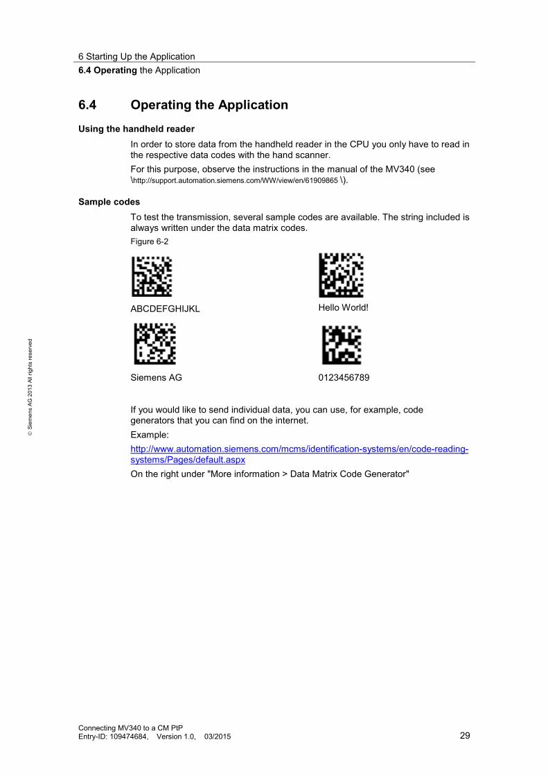
Sample codes To test the transmission, several sample codes are available. The string included is always written under the data matrix codes. Figure 6-2
ABCDEFGHIJKL
Hello World!
Siemens AG
0123456789
If you would like to send individual data, you can use, for example, code generators that you can find on the internet. Example: http://www.automation.siemens.com/mcms/identification-systems/en/code-reading-systems/Pages/default.aspx On the right under "More information > Data Matrix Code Generator"

6 Starting Up the Application 6.4 Operating the Application
Connecting MV340 to a CM PtP Entry-ID: 109474684, Version 1.0, 03/2015 30
S
iem
ens
AG 2
013
All r
ight
s re
serv
ed
Information of the Freeport_Overview monitoring table The Freeport_Overview monitoring table is included in the project. The table below shows you what information you can find in it. In the table, in the program itself you can find other comments. Table 6-7
Variable Note
“PtP_Freeport_DB".navi.state Indicates the current status of the program.
“PtP_Freeport_DB".RING_PLACE Indicates the location (in byte) of the ring buffers where the last telegram was stored.
“PtP_Freeport_DB".Control.Rcv_Length_save Shows the length (in byte) of the telegram last received.
“PtP_Freeport_DB".Control.P2P_NDR_save Shows the status of the telegram receipt last completed.
“PtP_Freeport_DB".Control.P2P_ERROR_save Shows the status of the last error message of the receive block.
“PtP_Freeport_DB".Control.Config_ERROR_save Shows the status of the last error message of the Config block.
“PtP_Freeport_DB".Control.Reset_ERROR_save Shows the status of the last error message of the Reset block.
7 Differences of the User Programs of S7-300 and S7-1500 6.4 Operating the Application
Connecting MV340 to a CM PtP Entry-ID: 109474684, Version 1.0, 03/2015 31
S
iem
ens
AG 2
013
All r
ight
s re
serv
ed
7 Differences of the User Programs of S7-300 and S7-1500
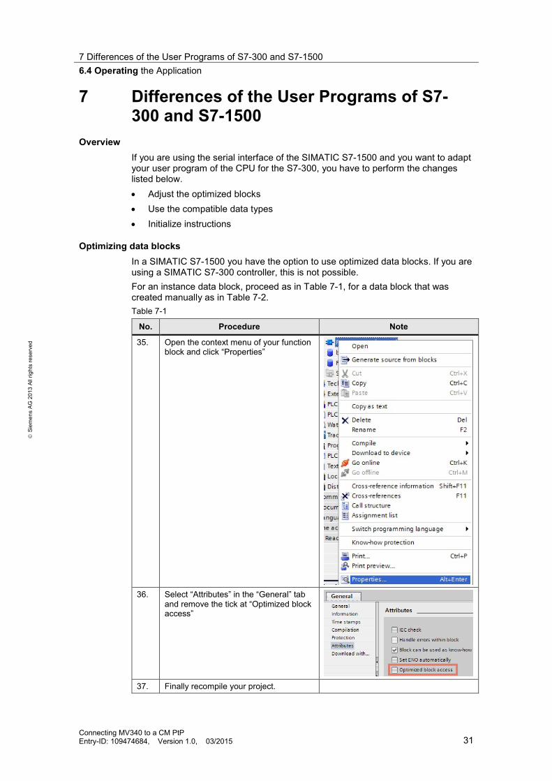
Overview If you are using the serial interface of the SIMATIC S7-1500 and you want to adapt your user program of the CPU for the S7-300, you have to perform the changes listed below. • Adjust the optimized blocks • Use the compatible data types • Initialize instructions
Optimizing data blocks In a SIMATIC S7-1500 you have the option to use optimized data blocks. If you are using a SIMATIC S7-300 controller, this is not possible. For an instance data block, proceed as in Table 7-1, for a data block that was created manually as in Table 7-2. Table 7-1
No. Procedure Note
35. Open the context menu of your function block and click “Properties”
36. Select “Attributes” in the “General” tab
and remove the tick at “Optimized block access”
37. Finally recompile your project.

7 Differences of the User Programs of S7-300 and S7-1500 6.4 Operating the Application
Connecting MV340 to a CM PtP Entry-ID: 109474684, Version 1.0, 03/2015 32
S
iem
ens
AG 2
013
All r
ight
s re
serv
ed
Table 7-2
38. Open the context menu of your data block and click “Properties”
39. Select “Attributes” in the “General” tab and remove the tick at “Optimized block access”
40. Finally recompile your project.
Adjusting incompatible data types Some data types that are known to a S7-1500 controller are not known to a S7-300 controller (for example, UInt, USInt, etc…). If you want to run your user program from a SIMATIC S7-1500 controller on a SIMATIC S7-300 controller, you have to replace your incompatible variables by suitable data types (e.g. Word or Byte).
Initializing the instructions For a SIMATIC S7-300 controller the instructions of the serial interface have to be initialized (see Figure 7-1). Figure 7-1
The following behavior has to be programmed: Table 7-3
No. Response Note
41. Program the first call of the instruction with COM_RST=1
For the first call the possibly existing REQ=0 input has to be set.
42. Request COM_RST. 43. If COM_RST=0 is set, you can continue
with your instruction calls just as in the SIMATIC S7-1500.

8 Related literature
Connecting MV340 to a CM PtP Entry-ID: 109474684, Version 1.0, 03/2015 33
S
iem
ens
AG 2
013
All r
ight
s re
serv
ed
8 Related literature This list is by no means complete and only reflects a selection of suitable information. Table 8-1
Topic Title
\1\ Link to this document
http://support.automation.siemens.com/WW/view/en/109474684
\2\ Siemens Industry Online Support
http://support.automation.siemens.com
\3\ SIMATIC MV340 Manual
http://support.automation.siemens.com/WW/view/en/61909865
\4\ CM PtP Configurations for Point‑ to‑ Point Connections
http://support.automation.siemens.com/WW/view/en/59057093
\5\ Device manual ET 200SP Communication Module CM PtP
http://support.automation.siemens.com/WW/view/en/59061378
\6\ Distributed I/O system ET 200SP
http://support.automation.siemens.com/WW/view/en/58649293
9 History Table 9-1
Version Date Modifications
V1.0 03/2013 First version