ansi-scte 55-2 2002 - out of band transport part 2 - mode b
DESCRIPTION
Out of band transportTRANSCRIPT

ENGINEERING COMMITTEE Digital Video Subcommittee
AMERICAN NATIONAL STANDARD
ANSI/SCTE 55-2 2002 (formerly DVS 167)
Digital Broadband Delivery System: Out Of Band Transport Part 2: Mode B

NOTICE
The Society of Cable Telecommunications Engineers (SCTE) Standards are intended to serve the public interest by providing specifications, test methods and procedures that promote uniformity of product, interchangeability and ultimately the long term reliability of broadband communications facilities. These documents shall not in any way preclude any member or nonmember of SCTE from manufacturing or selling products not conforming to such documents, nor shall the existence of such standards preclude their voluntary use by those other than SCTE members, whether used domestically or internationally. SCTE assumes no obligations or liability whatsoever to any party who may adopt the Standards. Such adopting party assumes all risks associated with adoption of these Standards or Recommended Practices, and accepts full responsibility for any damage and/or claims arising from the adoption of such Standards or Recommended Practices. Attention is called to the possibility that implementation of this standard may require use of subject matter covered by patent rights. By publication of this standard, no position is taken with respect to the existence or validity of any patent rights in connection therewith. SCTE shall not be responsible for identifying patents for which a license may be required or for conducting inquires into the legal validity or scope of those patents that are brought to its attention. Patent holders who believe that they hold patents which are essential to the implementation of this standard have been requested to provide information about those patents and any related licensing terms and conditions. Any such declarations made before or after publication of this document are available on the SCTE web site at http://www.scte.org.
All Rights Reserved
© Society of Cable Telecommunications Engineers, Inc. 140 Philips Road Exton, PA 19341

1
Table of Contents
1. INTRODUCTION 3
1.1 Revision History 3
1.2 Acronyms 3
1.3 References 4
2. DAVIC OUT OF BAND AND UPSTREAM SIGNALING 5
2.1 Downstream Physical Interface Specification 62.1.1 Quaternary Phase Shift Keying (QPSK) 72.1.2 Coaxial Cable Impedance 112.1.3 Framing Structure 112.1.4 Signaling Link Extended Superframe (SL-ESF) Framing Forms 112.1.5 SL-ESF Frame Overhead 122.1.6 ESF Frame Alignment Signal 122.1.7 ESF Cyclic Redundancy Check 122.1.8 ESF M-bit Data Link 132.1.9 SL-ESF Frame Payload Structure 142.1.10 Definition of Slot Configuration Fields 172.1.11 ATM Cell Structure 21
2.2 Upstream Physical Interface Specification 222.2.1 Quaternary Phase Shift Keying (QPSK) 222.2.2 Coaxial Cable Impedance 262.2.3 Time Division Multiple Access (TDMA) 26
2.2.3.1 Slot Definition 262.2.3.2 Slot Definition Assignment 27
2.2.4 Contention Based Access 272.2.4.1 Slot Definition 282.2.4.2 Positive Acknowledgment 28
2.2.5 Relationship between Downstream MAC Control Channels and Upstream Channels 282.2.6 Slot Location and Alignment for the QPSK Upstream Channels 28
2.2.6.1 Upstream Data Rate - 1.544 Mbps/s 292.2.6.2 Upstream Data Rate - 256 kbit/s 292.2.6.3 Upstream Data Rate - 3.088 Mbps/s 30
2.3 Media Access Control Functionality 312.3.1 MAC Reference Model 312.3.2 Upstream and Downstream Channel Types 32
2.3.2.1 Downstream Out of Band Channel Requirements 322.3.2.2 Upstream Channel Requirements 32
2.3.3 MAC Information Transport 322.3.4 MAC Message Types 34
2.3.4.1 MAC Initialization, Provisioning and Sign On 342.3.4.1.1 Initialization and Provisioning 352.3.4.1.2 Sign On and Calibration 35
2.3.4.2 Connection Management 372.3.4.2.1 Connection Establishment 37

2
2.3.4.2.2 Connection Release 402.3.4.3 MAC Link Management 41
2.3.4.3.1 Power and Timing Management 412.3.4.3.2 TDMA Allocation Management 412.3.4.3.3 Channel Error Management 42
2.3.4.4 MAC Message Definitions 422.3.4.4.1 Initialization, Provisioning and Sign On Messages 422.3.4.4.2 Connection Management Messages 502.3.4.4.3 Link Management Messages 612.3.4.4.4 MAC message timeouts 72
Table of FiguresFIGURE 2-1 SPECTRUM ALLOCATION FOR THE BI-DIRECTIONAL PHY ON COAX ............. 5FIGURE 2-2 SPECTRUM ALLOCATION FOR THE INTEGRATED UNIDIRECTIONAL AND
BI-DIRECTIONAL PASSBAND PHY ON A SINGLE COAX. ...................................................... 6FIGURE 2-3 DHCT OOB TRANSCEIVER CONCEPTUAL BLOCK DIAGRAM .............................. 6FIGURE 2-4 QPSK DOWNSTREAM TRANSMITTER POWER SPECTRUM.................................... 8FIGURE 2-5 SL-ESF FRAME STRUCTURE........................................................................................... 11FIGURE 2-6 SL-ESF PAYLOAD STRUCTURE FORMAT................................................................... 15FIGURE 2-7 CONCEPTUAL DIAGRAM OF THE CONVOLUTIONAL INTERLEAVER AND
DE-LEAVER........................................................................................................................................ 17FIGURE 2-8 BOUNDARY DEFINITIONS............................................................................................ 17FIGURE 2-9 SLOT BOUNDARY DEFINITION FIELD VALUES ...................................................... 18FIGURE 2-10 ADDITIONAL SLOT BOUNDARY DEFINITION FIELD VALUES FOR
EXTENDED RANGE CONTROL STATUS.................................................................................... 19FIGURE 2-11 RELATIONSHIP OF US SLOT TO DS INDICATOR................................................... 20FIGURE 2-12 ATM CELL STRUCTURE ............................................................................................... 21FIGURE 2-13 QPSK UPSTREAM TRANSMITTER POWER SPECTRUM........................................ 23FIGURE 2-14 UPSTREAM SLOT STRUCTURE.................................................................................... 27FIGURE 2-15 MAC REFERENCE MODEL............................................................................................ 31FIGURE 2-16 INITIALIZATION AND PROVISIONING SEQUENCE............................................. 35FIGURE 2-17 SIGN-ON MESSAGING SEQUENCE............................................................................ 36FIGURE 2-18 STATE DIAGRAM FOR RANGING AND CALIBRATION ...................................... 37FIGURE 2-19 CONNECTION ESTABLISHMENT SIGNALING SEQUENCE ................................ 39FIGURE 2-20 CONNECTION RELEASE SIGNALING....................................................................... 41
Table of TablesTABLE 1-1: ACRONYMS 3TABLE 2-1 QPSK DOWNSTREAM TRANSMITTER POWER SPECTRUM 8TABLE 2-2 SPECIFICATIONS FOR QPSK MODULATION (DOWNSTREAM) 9TABLE 2-3 EXTENDED SUPERFRAME OVERHEAD STRUCTURE 12TABLE 2-4 QPSK UPSTREAM TRANSMITTER POWER SPECTRUM 22TABLE 2-5 SPECIFICATIONS FOR QPSK MODULATION (UPSTREAM) 23TABLE 2-6 DAVIC MAC MESSAGES 34TABLE 2-7 MAC MESSAGE TIMEOUTS 72

3
1. Introduction
1.1 Revision History
Revision Date Editor DESCRIPTION
0.0 June 26, 1998 QPSK Out of Band Channels based on DAVIC, firstdraft
1.0 September 9, 1999 J. Bagley Changed typo of DAVIC 1.1 to DAVIC 1.2
2.0 March 10, 2000 J. Bagley Clarification and editorial changes
1.2 Acronyms
Table 1-1 provides a definition of the acronyms used throughout this document.
Table 1-1: AcronymsAAL ATM Adaptation LayerAAL1 ATM Adaptation Layer 1AAL5 ATM Adaptation Layer 5ACK AcknowledgeACS Access Control and SecurityAG Administrative GatewayAHE Analog HeadendAMS Alarms Management SubsystemAM-VSB Amplitude Modulation- Vestigal-
SidebandAPI Applications Programmatic
InterfaceARP Address Resolution ProtocolASN Abstract Syntax NotationATM Asynchronous Transfer ModeATSC Advanced Television System
CommitteeBASS Business Applications Support
SystemBCS Broadcast Control SuiteBFS Broadcast File ServerBM/G Broadband Multiplexer/GatewayBMM Broadcast Manager ModuleBOOTTERM Boot TerminalBOSS Business Operations Support
SystemBPS Bits per secondCA Conditional AccessCAA Conditional Access Authority
(PowerKEY)CAM Conditional Access ManagerCAT Conditional Access TableCATV Cable TelevisionCCM Continues Code ManagementCDN Cable Digital NetworkCDT Carrier Definition Table
CF Continuous FeedCFS Continuous Feed SessionCM Configuration ManagementCMB CRC Message BlockCMIP Common Management
Information ProtocolCMIS Common Management
Information ServiceCMS Customer Management SystemCORBA Common Object Request Broker
ArchitectureCRC Cyclical Redundancy CheckCS Convergence SublayerCW Control WordDAP Directory Access ProtocolDAVIC Digital Audio Visual CouncilDBAPI Database Application
Programming InterfaceDBDS Digital Broadband Delivery
SystemDBS Digital Broadcast ServiceDCT Display Channel TableDES Digital Encryption StandardDHCT Digital Home Communications
TerminalDHCTSE Digital Home Communications
Terminal Secure ElementDHEI Digital Headend Extended
InterfaceDIS Digital Interactive ServiceDMS Digital Multicast ServiceDMSI Digital Multicast Service
InformationDNCS Digital Network Control SystemDS-3 Digital Signal Level 3DSM-CC/DSMCC
Digital Storage Media Commandand Control
DVB-ASI Digital Video BroadcastingAsynchronous Serial Interface
DVB Digital Video Broadcasting(European)
DVSG Digital Video Software GroupEA Entitlement Agent (PowerKEY)EAI External Alarm InterfaceECM Entitlement Control MessageEIA Electronic Industries AssociationEID Entitlement IdentifierEM Element Manager . Generically,
any control software thatmanages hardware elements.
EMM Entitlement ManagementMessage
ENT Entitlement Name TableEPG Electronic Program GuideESBI External Status and Billing
InterfaceESF Extended Super FrameEUT Entitlement Unit TableFAS Frame Alignment SignalFAT Forward Applications TransportFDDI Fiber Data Distribution InterfaceFDM Frequency Division MultiplexedFEC Forward Error CorrectionFPM Forward Purchase MessagesFTP File Transfer ProtocolGBAM Global Broadcast Authenticated
MessageGOP Group Of PicturesGPS Global Positioning SystemGUI Graphical User InterfaceHEC Headend CodeHEX HexadecimalHFC Hybrid Fiber Coax
Revision History

4
HID Hub IDHRC Harmonically Related CarrierIANA Internet Assigned Number
AuthorityIBDS Interactive Broadband Delivery
SystemID IdentifierIDL Interface Definition LanguageIETF Internet Engineering Task ForceIGU Integrated Gateway UnitIP Internet ProtocolIPA Internet Protocol AddressIPPV Impulse Pay Per ViewIRC Incrementally Related CarrierITU International
Telecommunications UnionIVSN Interactive Video Services
NetworkIXC Inter-Exchange CarrierL1 Level 1LAN Local Area NetworkLCR Local Clock ReferenceLCT Logical Channel TableLDAP Lightweight Directory Access
ProtocolLOC Line of CodeLUG Line Up GroupMAC Media Access ControlMbps Mega-bits per secondMHz Mega-HertzMIB Management Information BaseMMDS Multi-Megabyte Digital ServiceMMT Modulation Mode TableMPEG Moving Pictures Expert GroupMSK Multi-Session KeyMUX MultiplexerN/A Not ApplicableNAK Not AcknowledgedNE Network ElementNFS Network File SystemNI Network InventoryNIC Network Information CenterNIT Network Information TableNMS Network Management SystemNSAP Network Service Access PointNTP Network Time ProtocolNTSC National Television System
CommitteeNVOD Near Video On DemandNVSC Non-Volatile Storage CellOC-3 Optical Carrier Level 3
OMG Object Management GroupOMS Object Management ServerONC Open Network ComputingOQPSK Offset Quadrature Phase Shift
KeyingORB Object Request BrokerOS Operating SystemOSF Operations System FunctionsOSI Open System InterconnectOSS Operations Support SystemOUI Organization Unique IdentifierPA Physical AddressPAT Program Association TablePCR Program Clock ReferencePDU Payload Data UnitPEN Private Enterprise NumberPES Packetized Elementary StreamPID Process IDPIN Personal Identification NumberPKCS Public Key Cryptography
StandardsPKYCS Power Key Control SuitePMT Program Map TablePOSIX Portable Operating System
Interface UnixPOTS Plain Old Telephone ServicePPV Pay Per ViewPRBS Pseudo-Random Bit StreamPS Program StreamPSI Program Specific InformationPVC Permanent Virtual CircuitQAM Quadrature Amplitude
ModulationQPSK Quadrature Phase Shift KeyingRDBMS Relational Database Management
SystemRF Radio FrequencyRPC Remote Procedure CallRS Reed-Solomon (coding)SAR Subassembly and ReassemblySAR-PDU Subassembly and Reassembly
Protocol Data UnitSET Secure Electronic TransactionSev SeveritySG Service GatewaySI Service InformationSID Session IdentifierSLIP Serial Line Internet ProtocolSM System ManagerSMS Subscriber Management System
SMI Structure of ManagementInformation
SN Sequence NumberSNP Sequence Number ProtectionSNMP Simple Network Management
ProtocolSNVM Secure Non-Volatile MemorySONET Synchronous Optical NetworkSP Service ProviderSPE Synchronous Payload EnvelopeSRM Session and Resource ManagerSSL Secure Sockets LayerSTS-3c Synchronous Transport Signal
level 3 concatenation (155.552Mbps)
SW SoftwareSWIF Single Wire InterfaceTCP Transport Control ProtocolTCP/IP Transport Control
Protocol/Internet ProtocolTDMA Time Division Multiple AccessTED Transition Encryption DecryptionTLI Transport Level InterfaceTMN Telecommunications
Management NetworkTS Transport StreamUDP User Datagram ProtocolUI User InterfaceUNISON Uni-directional SONETUPA Ultra SPARC Port ArchitectureUPS Universal Power SupplyUSID Universal Service IdentifierVASP Value-Added Service ProviderVBI Video Blanking IntervalVCI Virtual Circuit IndicatorVCR Video Cassette RecorderVCT Virtual Channel TableVOD Video On DemandVPI Virtual Path IndicatorVSP Video Service ProviderXDR External Data Representation
1.3 ReferencesReference Document
1 Digital Audio Visual Council 1.2 Specification part 8,“Lower Layer Protocols and Physical Interfaces” as of1997 (prior to any corrigenda)
2 ITU-T recommendation I.361, “B-ISDN ATM LayerSpecification”, November 1995
3 ITU-T recommendation I.363.5; “B-ISDN ATMAdaptation Layer specification: AAL5”, August 1996

5
2. DAVIC Out of Band and Upstream Signaling
The following has been extracted from the DAVIC 1.2 part 8 [Ref. 1] specification:Section 7.8, Passband Bi-directional PHY on coax. This does not include or track theissuance of corrigenda.
This Physical Layer Interface supports transmission over radio frequency coax (up to1GHz bandwidth). It is referred to as the bi-directional QPSK-link on HFC (HybridFiber Coax).
This Physical Layer Interface describes the complete physical layer structure, i.e.framing structure, channel coding and modulation for each direction Downstreamand Upstream). For the downstream QPSK modulation channel Grade A ismandatory and Grade B is optional. For the upstream QPSK channel Grade B ismandatory and Grades A and C are optional.
A summary of the spectrum allocation is depicted in Figure 2-1.
F req (M H z)
D o w nstream
U p stream
8 2 6 .5
7 0 1 30 ....
....
Q P S K m od u la ted chan nels (G rad e B - 1 .54 4M b /s) C h ann el spacing is 1 M H z k
Q P S K m od u la ted chann els (G rad e A - 1 .5 44M b/s) C han nel sp acin g is 1 M H z
Figure 2-1 Spectrum Allocation For the Bi-directional PHY on Coax
The Passband Bi-directional PHY on coax and the Passband Unidirectional PHY on coaxmay be used together on the same physical medium. Figure 2-2 shows the spectrumallocation in this case.

6
Freq
Downstream
Upstream
8 26.5
70 130....
....
QPSK modulated channels
QPSK modulated channels 54 1000
QAM modulated channels
Figure 2-2 Spectrum allocation for the integrated unidirectional andbi-directional passband PHY on a single coax.
Conceptual block diagrams of the DHCT transceivers are shown in Figure 2-3 .
Figure 2-3 DHCT OOB Transceiver Conceptual Block Diagram
2.1 Downstream Physical Interface Specification
To carry downstream information a combination of quaternary phase shift keying(QPSK) and a framing structure are specified. QPSK is specified due to its increased
ReedSolomonDecoder
(55,53)
ConvolutionalDeinterleaver
BittoByte
Mapping
SelfSynchronizedDerandomizer
&Framing
DifferentialDecoder
MatchedFilter
RF PhysicalInterface
&QPSK
Demodulator
RestofDHCT
ReedSolomonEncoder(59,53)
BytetoBit
MappingRandomizer
DifferentialEncoder
Addition ofUnique Word
QPSKModulator
RestofDHCT
DHCT out
MAC Protocol
DHCT inFrom RF

7
error performance, its spectral efficiency, and its low peak to average power allowtransmission at a high average power. The DAVIC specified Grade A QPSK ismandatory with Grade B being optional.
2.1.1 Quaternary Phase Shift Keying (QPSK)
QPSK modulation is used as a means of encoding digital information over wireline orfiber transmission links. The method is a subset of Phase Shift Keying (PSK) which isa subset of Phase Modulation (PM). Specifically QPSK is a four level use of digitalphase modulation (PM). Quadrature signal representations involve expressing anarbitrary phase sinusoidal waveform as a linear combination of a cosine wave and asine wave with zero starting phases.
The time-domain response of a square-root raised-cosine pulse with excessbandwidth parameter α is given by:
g t
tT
tT
tT
tT
tT
( )sin [ ( ) ] cos [ ( ) ]
[ ( ) ]=
− + +
−
π α α π απ α
1 4 1
1 4 2
where T is the symbol period.
The output signal shall be defined as
S t I g t nT f t Q g t nT f tn c nn
c( ) [ ( ) cos ( ) ( ) sin ( ) ]= • − • − • − •2 2π π
with In and Qn equal to ±1, independently from each other, and fc the QPSKmodulator’s carrier frequency.
The QPSK modulator divides the incoming bit stream so that bits are sent alternatelyto the in-phase modulator I and the out-of-phase modulator Q. These same bitstreams appear at the output of the respective phase detectors in the demodulatorwhere they are interleaved back into a serial bit stream.
The QPSK signal parameters are:
RF bandwidth BW= (fb / 2) * (1 + α )
Occupied RF Spectrum [fc - BW/2, fc + BW/2]
Symbol Rate fs = fb / 2
Nyquist Frequency fN = fs / 2
with fb = bit rate, fc = carrier frequency and a = excess bandwidth.

8
For both bit rates: 1.544 Mbps/s (Grade A) and 3.088 Mbps/s (Grade B), the PowerSpectrum at the QPSK transmitter shall comply to the Power Spectrum Mask given inTable 2-1 and
Figure 2-4. The Power Spectrum Mask shall be applied symmetrically around thecarrier frequency.
Table 2-1 QPSK Downstream Transmitter Power Spectrum
Figure 2-4 QPSK Downstream Transmitter Power Spectrum
QPSK systems require the use of differential encoding and corresponding differentialdetection. This is a result of the receivers having no method of determining if arecovered reference is a sine reference or a cosine reference. In addition, the polarityof the recovered reference is uncertain.
| ( f - fc ) / fN | Power Spectrum≤ 1-α 0 ± 0.25 dBat 1 -3 ± 0.25 dB
at 1+α ≤ -21 dB≥ 2 ≤ -40 dB
0 dB| (f - fc ) / fN |
H(f)
-3dB out-of-band
rejection
> 40dB-21 dB
11-α-40 dB
1+α 2
in-band ripple rm < 0.5 dB
rm
rN
Nyquist ripple rN .< 0.5 dB

9
Differential encoding transmits the information in encoded phase differencesbetween the two successive signals. The modulator processes the digital binarysymbols to achieve differential encoding and then transmits the absolute phases. Thedifferential encoding is implemented at the digital level.
The implementation of the QPSK (de)modulator shall comply to the specificationsgiven in Table 2-2.
Table 2-2 Specifications for QPSK Modulation (Downstream)
Table 2-2 Specifications for QPSK Modulation (Downstream)
Transmission Rate 1.544 Mbps/s for Grade A3.088 Mbps/s for Grade BA QPSK demodulator shall support Grade A (B is optional)
Modulation Differentially encoded QPSK.Transmit Filtering Filtering is α = 0.30 square root raised cosineChannel Spacing 1 MHz for Grade A
2 MHz for Grade BFrequency Step Size 250 kHz (center frequency granularity)Randomization After addition of the FEC bytes, MSB first byte to serial
conversion is performed and then, all of the 1.544 Mbps/sor 3.088 Mbps/s data is passed through a six register linearfeedback shift register (LFSR) randomizer to ensure arandom distribution of ones and zeroes. The generatingpolynomial is: x x6 5 1+ + . Randomizer:
Serial Input
Serial Output
D5 D4 D3 D2 D1 D0
Polynomial modulo 2 X6 + X5 + 1D = 1 bit clock delay register
A complementary self-synchronizing derandomizer is usedin the receiver to recover the data.Derandomizer:Serial Input
Serial Output
D5 D4 D3 D2 D1 D0
D = 1 bit clock delay register

10
Table 2-2 Specifications for QPSK Modulation (Downstream)
Differential Encoding Bytes entering the byte-to-symbol encoder are divided intofour bit pairs, each bit pair generating one QPSK symbol.Byte boundaries coincide with bit pair boundaries: that is,no bit pairs overlap two bytes. The bit pair correspondingto the MSBs of the byte is sent first. Within each bit pair,the more significant bit is referred to a ‘A’ and the lesssignificant as ‘B’. The differential encoder shall acceptbits(A,B) in sequence, and generate phase changes asfollows:
A B Phase Change0 0 none0 1 + 90 degrees1 1 180 degrees1 0 - 90 degrees
Initialization: The differential encoder state at the start ofthe payload (equivalent to at the end of the preamble) mustbe [I,Q]=[01].
Signal Constellation The outputs I, Q from the differential encoder map to thephase states as follows:
I
Q
Carrier Center FrequencyRange
70 to 130 MHz.The receiver shall operate over the entire specifiedfrequency range.
Frequency Stability +/- 50 ppm measured at the upper limit of the frequencyrange
Symbol Rate Accuracy +/- 50 ppmTransmitter Power SpectrumMask
A common mask for both bit rates: 1.544 Mbps/s (Grade A)and 3.088 Mbps/s (Grade B) is given in Table 2-1
Carrier Suppression > 30 dBI/Q Amplitude Imbalance < 1.0 dBI/Q Phase Imbalance < 2.0 degreeReceive Power Level at thedemodulator input(downstream out-of-band)
42 - 75 dBmicroV (RMS) (75 Ohm)
C/N at the DHCT input(Nyquist bandwidth, whitenoise)
> 20 dB for BER<1x10E-10 (after R/S error correction)(i.e. 1 error in 2 hours at 1.5 Mbps/s> 18 dB for BER <1x10E-6 before R/S error correction

11
2.1.2 Coaxial Cable Impedance
The coaxial cable nominal impedance shall be 75 Ohm over the frequency range asspecified in.
2.1.3 Framing Structure
The framing organization shall be based on Signaling Link Extended Superframe (SL-ESF) format, an SL-ESF payload structure, and an ATM cell structure.
2.1.4 Signaling Link Extended Superframe (SL-ESF) Framing Forms
The Signaling Link Extended Superframe (SL-ESF) frame structure is illustrated in .The bitstream is partitioned into 4632 bit Extended Superframes. Each ExtendedSuperframe consists of 24 193-bit frames. Each frame consists of 1 overhead (OH) bitand 24 bytes (192 bits) of payload.
Figure 2-5 SL-ESF Frame Structure
241 32 4 5 6 7 9 108 11 12 13 14 15 16 17 1819 20 21 22 23
24 Frames
24 Frames * 193 bits = 4632 bits
OH Payload
1 192 bits

12
2.1.5 SL-ESF Frame Overhead
There are 24 frame overhead bits in the Extended Superframe which are divided intoExtended Superframe Frame Alignment Signal (F1-F6), Cyclic Redundancy Check(C1-C6), and M-bit Data Link (M1-M12), as illustrated in Table 2-3.
Table 2-3 Extended Superframe Overhead Structure
2.1.6 ESF Frame Alignment Signal
The ESF Frame Alignment Signal (FAS) is used to locate all 24 frames and overheadbit positions. The bit values of the FAS are defined as follows:
F1 = 0, F2 = 0, F3 = 1, F4 = 0, F5 = 1, F6 = 1.
2.1.7 ESF Cyclic Redundancy Check
The Cyclic Redundancy Check field (Table 2-3) contains the CRC-6 check bitscalculated over the previous Extended Superframe (CRC Message block [CMB] size =4632 bits). Before calculation, all 24 frame overhead bits are equated to the value “1”.
FrameNumber Bit Number
Overhead BitData (192 bits)
1 0 M1 ♦ Slot Position 2 193 C1 3 386 M2 4 579 F1 = 0 5 772 M3 6 965 C2 7 1158 M4 8 1351 F2 = 0 9 1544 M5 ♦ Slot Position 10 1737 C3 11 1930 M6 12 2123 F3 = 1 13 2316 M7 14 2509 C4 15 2702 M8 16 2895 F4 = 0 17 3088 M9 ♦ Slot Position 18 3281 C5 19 3474 M10 20 3667 F5 = 1 21 3860 M11 22 4053 C6 23 4246 M12 24 4439 F6 = 1
FAS: Frame Alignment Signal (F1 - F6)DL: Mbps Data Link (M1 - M12)CRC: Cyclic Redundancy Check (C1 - C6)

13
All information in the other bit positions is unchanged. The check bit sequence C1-C6is the remainder after multiplication by x6 and then division by the generatorpolynomial x6+x+1 of the CMB. C1 is the most significant bit of the remainder. Theinitial remainder value is preset to all zeros.
2.1.8 ESF M-bit Data Link
The M-bits in the SL-ESF serve two purposes:
• to mark the slot positions for the upstream Contention based and Contentionlessbased signaling links
• to provide slot count information for upstream message bandwidth allocationmanagement in the DHCT.
M-bits M1, M5, and M9 mark the start of an upstream slot position for upstreammessage transmission.
Think of M-bits M10 - M1 as a register, which counts from 0 to N, where N is aninteger which indicates slot position cycle size (the value of N is sent in the MACDefault Configuration Message as Service_Channel_Last_Slot). The upstream slotposition register indicates the upstream slot positions that will correspond to the nextSL-ESF frame. Upstream slot positions are counted from 0 to N. There are 3 upstreamslots per upstream slot position when the upstream data rate is 1.544 Mbps/s, thereare 6 upstream slots per upstream slot position when the upstream data rate is 3.088Mbps/s, and there is 0.5 upstream slot per upstream slot position when the upstreamdata rate is 256 kbit/s. The corresponding upstream slot rates are, therefore, 3000upstream slots/sec when the upstream data rate is 1.544 Mbps/s, 6000 upstreamslots/sec when the upstream data rate is 3.088 Mbps/s, and 500 upstream slots/secwhen the upstream data rate is 256 kbit/s. The algorithm to determine the upstreamslot position counter value is given below:
if (downstream_rate == 3.088 Mbps/s) {n = 1;}else {n = 0;}
upstream_slot_position_register = value of M-bits latched at bit_position M11 (M10 -M1)
if (upstream_rate==1.544 Mbps/s) { m = 3;}else if (upstream_rate==3.088 Mbps/s) {m = 6;}else {m = 0.5}
if ( bit_position==M1 and previous M12 ==1){ upstream_slot_position_counter = upstream_slot_position_register * 3 * m; }

14
if ( bit_position == M5)if ( (n == 0) or (n == 1 and previous M12 == 0) ){ upstream_slot_position_counter = upstream_slot_position_counter+m; }
if (bit_position == M9)if ( (n = 0) or (n = 1 and previous M12 == 1) ){ upstream_slot_position_counter = upstream_slot_position_counter + m; }
if (bit_position == M11){ temp_upstream_slot_position_register = (M10, M9, M8, ...., M1); }
if ( (bit_position == M12 ) and ( M12 == 1) ){upstream_slot_position_register = temp_upstream_slot_position_register;}
where, the M-bits (see Table 2-3) will be defined as follows:
M1 - M10 = 10 bit ESF counter which counts from 0 to N with M10 themost significant bit (MSB);
M11 = odd parity for the ESF counter, i.e., M11 = 1 if the ESF_value(M1-M10) has an even number of bits set to 1;
M12 = 1: ESF counter valid0; ESF counter not valid
The values assigned to M12 are as follows:
(1) When the QPSK downstream channel bit rate is 1.544 Mb/s, the M12 bit, is alwaysset to the value ‘1’.
(2) When the QPSK downstream channel bit rate is 3.088 Mb/s, the information isalways transmitted in pairs of superframe, where superframe-A is the firstsuperframe in the pair, and superframe-B is the second superframe in the pair. In thiscase, the M12 bit of superframe-A is set to the value ‘0’ and the M12 bit ofsuperframe-B is set to the value ‘1’.
2.1.9 SL-ESF Frame Payload StructureThe SL-ESF frame payload structure provides a known container for defining the location of the ATMcells and the corresponding Reed Solomon parity values. The SL-ESF payload structure is shown inFigure 2-6

15
Figure 2-6 SL-ESF Payload Structure Format
The SL-ESF payload structure consists of 5 rows of 57 bytes each, 4 rows of 58 byteseach which includes 1 byte trailer, and 1 row of 59 bytes, which includes a 2 bytetrailer. The first bit of the SL-ESF payload structure follows the M1 bit of the SL-ESFframe. The SL-ESF payload fields are defined as follows.
The two T fields shall be set to 0 to facilitate future enhancements.
Rxa-Rxc is a 24 bit field containing slot configuration information for the relatedupstream channel “x” and is defined as:
Rxa = (b0 .....b7)Rxb = (b8.....b15)Rxc = (b16... b23)
qpsk_x_slot_configuration = (b0......b23)
= slot configuration information for theupstream channel “x”
where
b0 = ranging control slot indicator for next 3ms periodb1-b6 = slot boundary definition field for next 3ms periodb7 = slot 1 reception indicator for second previous 3ms periodb8 = slot 2 reception indicator for second previous 3ms periodb9 = slot 3 reception indicator for second previous 3ms periodb10 = slot 4 reception indicator for second previous 3ms periodb11 = slot 5 reception indicator for second previous 3ms periodb12 = slot 6 reception indicator for second previous 3ms periodb13 = slot 7 reception indicator for second previous 3ms periodb14 = slot 8 reception indicator for second previous 3ms periodb15 = slot 9 reception indicator for second previous 3ms period
1 ← 2 → ← 53 → ← 2 →1 R1a R1b ATM Cell RS parity2 R1c R2a R2b3 R2c R3a4 R3b R3c R4a5 R4b R4c6 R5a R5b R5c7 R6a R6b8 R6c R7a R7b9 R7c R8a10 R8b R8c T T

16
b16-17 = reservation control for next superframeb18-b23 = CRC 6 parity (see definition in SL-ESF section)
When the upstream data channel is a 256 kbit/s data channel, then only the firstthree slot reception indicators are valid. These slots indicator refer to the threeavailable slots which span over two 3ms period periods in the 256 kbit/s. When theupstream data channel is a 3.088 Mb/s data channel, two consecutiveqpsk_slot_configuration fields are used. The definition of the first slot configurationfield is unchanged. The definition of the second slot configuration field extends theboundary definition to upstream slots 10 through 18, and the reception indicatorscover upstream slots 10 through 18.
When the Downstream MAC channel is a 3.088 Mbps/s data channel, the SlotConfiguration fields in superframe-B are used when one or more 3.088 Mbps/supstream QPSK channels are being utilized. The index for the overhead bytes insuperframe-B will be R9a, R9b...., R16a, R16b, R16c.
Reed-Solomon encoding shall be performed on each ATM cell with T=1. This meansthat 1 erroneous byte per ATM cell can be corrected. This process adds 2 parity bytesto the ATM cell to give a codeword of (55,53).
The Reed-Solomon code shall have the following generator polynomials:
Code Generator Polynomial: g(x) = (x + µµµµ0)( x + µµµµ1), where µµµµ=02hex
Field Generator Polynomial:p(x) = x8 + x4 + x3 + x2 + 1
Convolutional interleaving shall be applied to the ATM cells contained in the SL-ESF.The Rxa - Rxc bytes and the two T bytes shall not be included in the interleavingprocess. Convolutional interleaving is applied by interleaving 5 lines of 55 bytes.
Following the scheme of Figure 2-7 , convolutional interleaving shall be applied tothe error protected packets. The Convolutional interleaving process shall be based onthe Forney approach, which is compatible with the Ramsey type III approach, withI=5. The Interleaved frame shall be composed of overlapping error protected packetsand a group of 10 packets shall be delimited by the start of the SL-ESF.
The interleaver is composed of I branches, cyclically connected to the input byte-stream by the input switch. Each branch shall be a First In First Out (FIFO) shiftregister, with depth (M) cells (where M = N/I, N = 55 = error protected frame length,I = interleaving depth). The input and output switches shall be synchronized.
For synchronization purposes, the first byte of each error protected packet shall bealways routed into the branch "0" of the interleaver (corresponding to a null delay).The third byte of the SL-ESF payload (the byte immediately following R1b) shall bealigned to the first byte of an error protected packet.
The deinterleaver is similar, in principle, to the interleaver, but the branch indexesare reversed (i.e. branch 0 corresponds to the largest delay). The deinterleaver

17
synchronization is achieved by routing the third data byte of the SL-ESF into the "0"branch.
Figure 2-7 Conceptual Diagram of the Convolutional Interleaver and De-leaver
2.1.10 Definition of Slot Configuration Fields
Ranging Control Slot Indicator (b0) - When this bit is active (b0 = 1), the first threeslots of upstream channel “x” which correspond to the occurrence of the next 3 msecperiod are designated as ranging control slots. A ranging control message may betransmitted in the second ranging control slot, and the first and third ranging controlslots may not be used for transmission (guard band for ranging operations).
Slot Boundary Definition field (b1-b6) - Slot types are assigned to upstream slotsusing bits b0-b6. The slots are grouped into regions within the 3 msec period suchthat slots of a similar type are contained within the same region. The order of theregions is Ranging slot, Contention based slots, Reserved slots and Contentionlessbased slots. If a ranging slot is available within a 3 msec period it will consist of thefirst three slot times in the 3 msec period. A ranging slot is indicated by b0 = 1. Theboundaries between the remaining regions of the 3 msec are defined by b1-b6. Theboundaries are defined in Figure 2-8
Figure 2-8 Boundary Definitions
0
M
M M
M M M
M M M M
M M M M
M M M
M M
M
0
0
2
1
3
4
0
2
1
3
4
IN OUT
CHANNEL
Boundary 0Boundary 1 slot 1Boundary 2 slot 2Boundary 3 slot 3Boundary 4 slot 4Boundary 5 slot 5Boundary 6 slot 6Boundary 7 slot 7Boundary 8 slot 8Boundary 9 slot 9

18
The boundary positions are defined by b1-b6 in Figure 2.9.,
row = Contention based / Reserved region boundary
column = Reserved packet /Contentionless based region boundary
(example : b0 = 0, b1-b6 = 22: Contention (1-2), Reserved (3-5), Contentionless (6-9))
Figure 2-9 Slot Boundary Definition Field Values
The remaining values of the Slot Boundary Definition Field are providedin Figure 2-10 .
0 1 2 3 4 5 6 7 8 9
0* 0 1 2 3 4 5 6 7 8 9
1* 10 11 12 13 14 15 16 17 18
2* 19 20 21 22 23 24 25 26
3 27 28 29 30 31 32 33
4 34 35 36 37 38 39
5 40 41 42 43 44
6 45 46 47 48
7 49 50 51
8 52 53
9 54
(*) note: When the ranging control slot indicator (b0)is set to “1”, the values in rows 0 - 2 are illegalvalues, and values in row 3 means that there are noaloha slots, because slots 1-3 are defined as rangingcontrol slots.

19
Note: For b1-b6 = 55 - 63, b0 must be set to 1.
Figure 2-10 Additional Slot Boundary Definition Field Valuesfor Extended Range Control Slots
The values in Figure 2-9 and Figure 2-10 are derived from b1-b6 in the followingmanner:
b1 + (b2 * 2) + (b3 * 4) + (b4 * 8) + (b5 * 16) + (b6 * 32)
When the upstream data channel is a 256 kbit/s data channel, then only the firstthree slot boundary positions are valid. In this case, only the first three rows andcolumns in Figure 2- 9 are valid, and Figure 2-10 is not valid. When the upstreamdata channel is a 3.088 mbit/s data channel, each slot boundary definition fieldapplies to 9 slots within the 3 msec period. In this case, there will be two slotboundary definition fields which define the 3 msec period.
Slot Reception Indicators (b7 - b15) - When a slot reception indicator is active (“1”),this indicates that a cell was received without collision. The relationship between agiven US slot and its indicator is shown in Figure 2-11. When the indicator is inactive(“0”), this indicates that either a collision was detected or no cell was received in thecorresponding upstream slot.
b1-b6value
Ranging Controlslots
Contentionslots
reservationslots
Contentionlessslots
55 1-6 7-9 - -56 1-6 7-8 - 957 1-6 7 8-9 -58 1-6 7 8 959 1-6 7 - 8-960 1-6 - 7-8 961 1-6 - 7 8-962 1-6 - - 7-963 1-9 - - -

20
Figure 2-11 Relationship of US Slot to DS Indicator
Reservation Control (b16-b17) - When the reservation control field has the value of 0,no reservation attempts are allowed to be transmitted on the corresponding QPSKupstream channel during the slot positions associated with the next 3 msec period.When the reservation control field has the value of 1, reservation attempts can bemade. The values 2 and 3 are reserved.
CRC 6 Parity (b18-b23) - This field contains a CRC 6 parity value calculated over theprevious 18 bits. The CRC 6 parity value is described in the SL-ESF frame formatSection.
In the case where there is more than one OOB DS QPSK channel related to anupstream QPSK channel, the SL-ESF overhead bits and the payload R-bytes shall beidentical in those OOB DS channels, with the exception of the overhead CRC (C1-C6)bits, which are specific to each of those OOB DS channels. Such related DS channelsshall be synchronized.
1.544Mbit/s Downstream 3.088 Mbps/s Downstream
256 kbit/sUpstream DS
US
I
3 slots
1 Frame
DS
US
II
3 slots
1 Frame
1.544Mbps/sUpstream
DS
US
I
9 slots
1 Frame
DS
US
II
9 slots
1 Frame
3.088Mbps/sUpstream
DS
US
I
18 slots
1 Frame
DS
US
II
18 slots
1 Frame
Notes1) 'I' indicates the downstream frame(s) in which Indicators (contained within the MAC Flag Sets)
are sent. These indicators control the upstream slots in the shaded area.2) In the 3.088 downstream, two successive frames contain MAC Flag Sets 0..151. Two successive MAC Flag Sets are used to control the 18 slots of a 3.088 upstream channel.

21
The MAC messages that are required to perform the MAC functions for the upstreamchannel shall be transmitted on each of its related OOB DS channels.
2.1.11 ATM Cell Structure
Figure 2-12 ATM Cell Structure
The format for each ATM cell structure is illustrated in Figure 2-12 . This structureand field coding shall be consistent with the structure and coding given in[ITU-T I.361 [Ref. 2] for ATM UNI, both for the ATM and non-ATM based passbandbi-directional PHY on coax.
Information PayloadHeader
384 bits40 bits
53 bytes

22
2.2 Upstream Physical Interface Specification
To carry upstream information a combination of quaternary phase shift keying(QPSK) and a Time Division Multiplexing structure are specified. QPSK is specifieddue to its increased error performance, its spectral efficiency, and its ability to betransmitted at higher than average power levels. DAVIC specified Grade B ismandatory with Grades A and C being optional.
2.2.1 Quaternary Phase Shift Keying (QPSK)
An overview of QPSK modulation has been provided in the downstream QPSKmodulation section.
The QPSK signal parameters are:
RF bandwidth BW= (fb / 2) * (1 + α )
Occupied RF Spectrum [fc - BW/2 , fc + BW/2]
Symbol Rate fs = fb / 2
Nyquist Frequency fN = fs / 2
with fb = bit rate, fc = carrier frequency and α = excess bandwidth.
For all three bit rates: 256 kbit/s (Grade A), 1.544 Mbps/s (Grade B) and 3.088Mbps/s (Grade C), the Power Spectrum at the QPSK transmitter shall comply to thePower Spectrum Mask given in Table 2-4 and Figure 2-13 . The Power SpectrumMask shall be applied symmetrically around the carrier frequency.
Table 2-4 QPSK Upstream Transmitter Power Spectrum| ( f - fc ) / fN | Power Spectrum
≤ 1-α 0 ± 0.25 dBat 1 -3 ± 0.25 dB
at 1+α ≤ -21 dB≥ 2 ≤ -40 dB

23
Figure 2-13 QPSK Upstream Transmitter Power Spectrum
The specifications which shall apply to QPSK modulation for the upstream channel are givenin Table 2-5.
Table 2-5 Specifications for QPSK Modulation (Upstream)
Specifications for QPSK Modulation(Upstream)
Transmission Rate Three grades of modulation transmission rate are specified:Grade RateA 256 kbit/sB 1.544 Mbps/sC 3.088 Mbps/s
A QPSK modulator (transmitter) shall support B grade of transmission with A and C gradesof transmission being optional. A QPSK demodulator (receiver) shall support B grade with Aand C being optional.
Modulation Differentially encoded QPSKTransmit Filtering α = 0.30 square root raised cosine for Grade A (256 kbit/s), Grade B (1.544 Mbps/s), and
Grade C (3.088 Mbps/s)Channel Spacing 200 kHz for Grade A (256 kbit/s)
1 MHz for Grade B (1.544 Mbps/s)2 MHz for Grade C (3.088 Mbps/s)
Frequency Step Size 50 kHz for Grade A, Grade B, and Grade CUnique Word The unique word is four bytes: CC CC CC 0D hex, transmitted in this order.
0 dB| (f - fc ) / fN |
H(f)
-3dB out-of-band
rejection
> 40dB-21 dB
11-α-40 dB
1+α 2
in-band ripple rm < 0.5 dB
rm
rN
Nyquist ripple rN .< 0.5 dB

24
Specifications for QPSK Modulation(Upstream)
Randomization The unique word shall be sent in the clear. After addition of the FEC bytes, randomizationshall apply only to the 53-byte payload area and 6 FEC bytes, with the randomizer performingmodulo-2 addition of the data with a pseudo-random sequence. The generating polynomial isx x6 5 1+ + with seed all ones.Byte/serial conversion shall be MSB first. The 472-bit binary sequence generated by the shiftregister starts with 00000100… The first “0” is to be added to the first bit after the uniqueword.Randomizer:
Serial Input
Serial Output
D5 D4 D3 D2 D1 D0
Polynomial modulo 2 X6 + X5 + 1D = 1 bit clock delay register
1 1 1 1 1 1seed value = all 1s
A complementary non self-synchronizing derandomizer is used in the receiver to recover thedata. The derandomizer shall be enabled after detection of the unique word.Derandomizer:
Serial Input
Serial Output
D5 D4 D3 D2 D1 D0
D = 1 bit clock delay register
1 1 1 1 1 1reseed value all 1s
Differential Encoding Bytes entering the byte-to-symbol encoder are divided into four bit pairs, each bit pairgenerating one QPSK symbol. Byte boundaries coincide with bit pair boundaries: that is, nobit pairs overlap two bytes. The bit pair corresponding to the MSBs of the byte is sent first.Within each bit pair, the more significant bit is referred to a ‘A’ and the less significant as ‘B’.The differential encoder shall accept bits (A,B) in sequence, and generate phase changes asfollows:
A B Phase Change0 0 none0 1 + 90 degrees1 1 180 degrees1 0 - 90 degrees

25
Specifications for QPSK Modulation(Upstream)
Signal Constellation The outputs I, Q from the differential encoder map to the phase states as follows:
I
Q
1101
1000
This constellation is used for the detection of the Unique Word, which is not differentiallyencoded.
Carrier CenterFrequency Range
8 - 26.5 MHz. The transmitter shall operate over the entire specified frequency range. Thelowest carrier center frequency is 8 MHz.
Frequency Stability +/- 50 ppm measured at the upper limit of the frequency rangeSymbol Rate Accuracy +/- 50 ppmTransmitter PowerSpectrum Mask
A common mask for all three bit rates: 256 kbit/s (Grade A), 1.544 Mbps/s (Grade B) and3.088 Mbps/s (Grade C) is given in Table 2-4.
Carrier Suppressionwhen Transmitter Active
> 30 dB
Carrier Suppressionwhen Transmitter Idle
The Carrier Suppression shall be more than 60 dB below nominal power output level, over theentire power output range and 30 dB right after or before transmission. Details are shown inthe figure below.NOTE: Idle Transmitter Definition: A terminal is considered to be idle if it is 3 slots before animminent transmission or 3 slots after its most recent transmission.
Burst Packet3 slots 3 slots
Guard Band
60 dB60 dB30 dB 30 dB
63 Bytes 1 Byte1 Byte
I/Q AmplitudeImbalance
< 1.0 dB
I/Q Phase Imbalance < 2.0 degreeTransmit Power Level atthe modulator output(upstream)
85 - 113 dBmicroV (RMS) (75 Ohm)
C/N at the demodulatorinput at the A3 referencepoint (Nyquistbandwidth, white noise)
> 20 dB @ 1x10E-6 packet loss (after error correction)NOTE: A packet loss occurs when one or more bit per packet(after error correction) are uncorrectable.

26
2.2.2 Coaxial Cable Impedance
The coaxial cable nominal impedance shall be 75 Ohm over the frequency range asspecified, see .
2.2.3 Time Division Multiple Access (TDMA)
TDMA allows a DAVIC DHCT access onto a signaling channel for upstreamApplication control information. The TDMA technique is used for communicationbetween the DHCT and the Service Provider System. TDMA is based on dividingaccess by multiple set-top units onto a shared signaling channel. This techniqueprovides a negotiated bandwidth allocation slot access method.
2.2.3.1 Slot DefinitionThe TDMA technique utilizes a slotting methodology which allows the transmit starttimes to be synchronized to a common clock source. Synchronizing the start timesincreases message throughput of this signaling channel since the message packets donot overlap during transmission. The period between sequential start times areidentified as slots. Each slot is a point in time when a message packet can betransmitted over the signaling link.
The time reference for slot location is received via the downstream channelsgenerated at the Delivery System and received simultaneously by all set-top units.Since all DHCTs reference the same time base, the slot times are aligned for allDHCTs. However, since there is propagation delay in any transmission network, atime base ranging method accommodates deviation of transmission due topropagation delay.
The upstream slot rates are 3000 upstream slots/sec when the upstream data rate is1.544 Mbps/s and 500 upstream slots/sec when the upstream data rate is 256 kbit/s.
The format of the upstream slot is shown in Figure 2-14. A Unique Word (UW) (4bytes) provides a burst mode acquisition method. The payload area (53 bytes)contains a single message cell as described previously. The RS Parity field (6 bytes)provides t=3 Reed Solomon protection RS(59,53) over the payload area. The Guardband (1 byte) provides spacing between adjacent packets.
Reed-Solomon encoding shall be performed on each ATM cell with T=3. This meansthat 3 erroneous byte per ATM cell can be corrected. This process adds 6 parity bytesto the ATM cell to give a codeword of (59,53). Reed-Solomon encoding is performedon the ATM cell before upstream data randomization.
The Reed-Solomon code shall have the following generator polynomials:
Code Generator Polynomial: g(x) = (x + µµµµ0)( x + µµµµ1) (x + µµµµ2) ... ( x + µµµµ5),
where µµµµ=02hex
Field Generator Polynomial: p(x) = x8 + x4 + x3 + x2 + 1

27
Figure 2-14 Upstream Slot Structure
This structure and field coding shall be consistent with the structure and codinggiven in [ITU-T I.361] [Ref. 2] for ATM UNI.
2.2.3.2 Slot Definition AssignmentSince the TDMA signaling link is used by DHCTs that are engaged in interactivesessions, the number of available message slots on this channel is dependent on thenumber of simultaneous users. When messaging slots are not in use, an DHCT maybe assigned multiple message slots for increased messaging throughput. Additionalslot assignments are provided to the DHCT from the downstream signalinginformation flow.
2.2.4 Contention Based Access
Upstream session related control information and network related controlinformation are provided via a service channel using quaternary phase shift keying(QPSK) along with a contention-based protocol.
Contention based access is used for managing contention of transmission over asignaling link. For the DAVIC system, this protocol is utilized as a technique forsignaling between an DHCT and the Delivery System’s Service-Related Controlfunction. Contention based access provides instant channel allocation for the DHCT.
The Contention based technique is used for multiple subscribers that will have equalaccess to the signaling channel. It is probable that simultaneous transmissions willoccur. The Contention based technique provides resolution of signaling throughputwhen simultaneous transmissions occur.
Payload Area Guard Band
53 bytes 1 byte
UW
4 bytes
RS Parity
6 bytes

28
2.2.4.1 Slot DefinitionThe slot definition utilized for the contention based access is the same as that definedin the TDMA section, 2.2.3.1.
2.2.4.2 Positive AcknowledgmentFor each ATM cell transmitted by the DHCT, a positive acknowledgment is sent backby the NMS, utilizing the reception indicator field, for each successfully receivedATM cell. In contention based access mode, a positive acknowledgment indicatesthat a collision did not occur. A collision occurs if two or more DHCTs attempt ATMcell transmission during the same slot. A collision will be assumed if a DHCT doesnot receive a positive acknowledgment. If a collision occurs, then the DHCT willinitiate a retransmission procedure.
2.2.5 Relationship between Downstream MAC Control Channels and UpstreamChannels
Up to 8 QPSK Upstream channels can be related to each downstream channel whichis designated as a MAC control channel. This relationship consists of the followingitems:
(1) Each of these related upstream channels share a common slot position. Thisreference is based on 1 millisecond time markers that are derived via informationtransmitted via the downstream MAC control channel.
(2) Each of these related upstream channels derive slot numbers from informationprovided in the downstream MAC control channel.
(3) The Messaging needed perform MAC functions for each of these relatedupstream channels is transmitted via the downstream MAC control channel.
2.2.6 Slot Location and Alignment for the QPSK Upstream Channels
Transmission on each QPSK upstream channel is based on dividing access bymultiple DHCTs by utilizing a negotiated bandwidth allocation slot access method. Aslotting methodology allows the transmit slot locations to be synchronized to acommon slot position reference, which is provided via the related downstream MACcontrol channel. Synchronizing the slot locations increases message throughput of theupstream channels since the ATM cells do not overlap during transmission.
The slot position reference for upstream slot locations is received via the relateddownstream MAC control channel by each DHCT. Since each DHCT receives thedownstream slot position reference at a slightly different time, due to propagationdelay in the transmission network, slot position ranging is required to align theactual slot locations for each related upstream channel. The upstream slot rates are3000 upstream slots/sec when the upstream data rate is 1.544 Mbps/s and 500upstream slots/sec when the upstream data rate is 256 kbit/s.
The number of slots available in any one second is given by

29
number of slots/sec = (upstream data rate / 512 ) + extra guardband
where extra guardband may be designated between groups of slots for alignmentpurposes.
2.2.6.1 Upstream Data Rate - 1.544 Mbps/sIn the case where the upstream data rate is 1.544 Mbps/s, the upstream slots arenumbered as shown below, where k is a multiple of 9.
← 3 msec time period →s(k-1) s(k) s(k+1) s(k+2) s(k+3) s(k+4) s(k+5) s(k+6) s(k+7) s(k+8) s(k+9)
� � � �
3 slot position references (downstream) per 3 msec time period
The relationship between the received slot position reference and the actual slottransmit position is given by:
slot_transmit_position = slot_position_reference + slot_position_offset
where slot_position_offset is derived from the Time_Offset_Value provided via theRange_and_Power_Calibration_Message.
← slot_transmit_positionslot (j-1) slot (j)
� slot_position_offset �
� slot position reference (downstream)
In the case where the upstream data rate is 1.544 Mbps/s, the actual slot transmissionlocations are given by
slot_transmission_location (m) = slot_transmission_position + (m * 512);
where m = 0,1,2; is the position of the slot with respect to theslot_transmission_position
←slot_transmission_position ←slot_transmission_position� position 0 � position 1 � position 2
previous slot slot 0 (m=0) slot 1 (m=1) slot 2 (m=2) next slot512 bits 512 bits 512 bits
2.2.6.2 Upstream Data Rate - 256 kbit/sIn the case where the upstream data rate is 256 kbit/s, the upstream slots arenumbered as shown below, where k is a multiple of 3.:

30
← 6 msec time period →s(k-1) s(k) s(k+1) s(k+2) s(k+3)
� � � � � � �
6 slot position references (downstream) per 6 msec time period
The relationship between the received slot position reference and the actual slottransmit position is given by:
slot_transmit_position = slot_position_reference (integer) + slot_position_offsetwhere only the slot_position_references corresponding to integer values are validand the slot_position_offset is derived from the Time_Offset_Value provided via theRange_and_Power_Calibration_Message.
← slot_transmit_positionslot (j-1) slot (j)
� slot_position_offset �
� slot position reference, integer value (downstream)
In the case where the upstream data rate is 256 kbit/s, the actual slot transmissionlocations correspond directly to the integer valued slot position references.
2.2.6.3 Upstream Data Rate - 3.088 Mbps/sIn the case where the upstream data rate is 3.088 Mbps/s, the upstream slots arenumbered as shown below, where k is a multiple of 18.
← 3 msec time period →s(k-1) k k
+1
k+2
k+3
k+4
k+5
k+6
k+7
k+8
k+9
k+10
k+11
k+12
k+13
k+14
k+15
k+16
k+17
s(k+18)
� � � �
3 slot position references (downstream) per 3 msec time period
The relationship between the received slot position reference and the actual slottransmit position is given by:
slot_transmit_position = slot_position_reference + slot_position_offset
where slot_position_offset is derived from the Time_Offset_Value provided via theRange_and_Power_Calibration_Message.
In the casewhere the
upstream data rate is 3.088 Mbps/s, the actual slot transmission locations are givenby
← slot_transmit_positionslot (j-1) slot (j)
� slot_position_offset �
� slot position reference (downstream)

31
slot_transmission_location (m) = slot_transmission_position + (m * 512);
where m = 0,1,2,3,4,5; is the position of the slot with respect to theslot_transmission_position
←slot_transmission_position ←slot_transmission_position� pos0
� pos1
� pos2
� pos3
� pos4
� pos5
previous slot slot 0(m=0)
slot1(m=1)
slot 2(m=2)
slot 3(m=3)
slot 4(m=4)
slot 4(m=5)
next slot
512bits
512bits
512bits
512bits
512bits
528bits
2.3 Media Access Control Functionality
This section contains the specifications for Media Access Control (MAC) Protocol tobe used for communication across a Hybrid Fiber Coax (HFC) network. It specifiesthe communication between Network Related Control (NMS) at the AccessSubnetwork and the Digital Home Cable Terminal (DHCT).
2.3.1 MAC Reference Model
The scope of this section is limited to the definition and specification of the MACLayer protocol. The detailed operations within the MAC layer (Figure 2-15) arehidden from the above layers.
Figure 2-15 MAC Reference Model
Higher Layers
LinkManagement
ConnectionManagement
Singlecast Address Resolution
Muticast Address Resolution
MAC Signaling
DataAdaptation
Initialization,Sign-on andProvisioningManagement
MAC Management
Physical Layer
MACSublayerLower
LayerProtocols

32
This section focuses on the required message flows between the NMS and the DHCTfor Media Access Control. These areas are divided into three categories: Initialization,Provisioning and Sign On Management, Connection Management and LinkManagement.
2.3.2 Upstream and Downstream Channel Types
This section defines the upstream and downstream channel types supported by theMedia Access Control Protocol.
2.3.2.1 Downstream Out of Band Channel RequirementsThe Media Access Control Protocol supports multiple downstream Channels. Ininstances where multiple Channels are used, the NMS shall specify a single Out ofBand frequency where DHCTs perform Initialization, Provisioning and Sign OnFunctions. In instances where only a single frequency is in use, the NMS shall utilizethat frequency for Initialization, Provisioning and Sign On functions.
2.3.2.2 Upstream Channel RequirementsThe Media Access Control protocol supports multiple upstream channels. One of theupstream channels shall be designated the Service Channel. The Service Channelshall be used by DHCTs entering the network via the Initialization, Provisioning andSign-On procedure. The remaining upstream channels shall be used for upstreamdata transmission. In cases where only one upstream channel is utilized, thefunctions of the Service Channel shall reside in conjunction with regular upstreamdata transmission.
2.3.3 MAC Information Transport
To support the delivery of MAC related information to and from the DHCT, adedicated Virtual Channel shall be utilized. The VPI,VCI for this channel shall be0x000,0x0021.
AAL5 (as specified in [ITU-T I.363.5] [Ref. 3]) adaptation shall be used to encapsulateeach MAC SDU in ATM cells. All upstream MAC messages shall be restricted to asingle cell. A single cell MAC SDU can accommodate up to 40 bytes.
Since MAC related information is terminated at the DHCT and NMS a privatelydefined message structure will be utilized. The format of the MAC message structureis illustrated below.
Note: All messages are sent most significant bit first.

33
MAC_message(){ Bits Bytes
Bit Number /Description
Message_Configuration 1Protocol_Version 5 7..3:{enum}Syntax_Indicator 3 2..0:{enum}
Message_Type 8 1if (Syntax_Indicator==001) {MAC_Address 48 6}MAC_Information_Elements () N
}
Protocol Version
Protocol_Version is a 5 bit enumerated type used to identify the current MACversion.
enum Protocol_Version { DAVIC 1.0 Compliant Device,SCTE OOB Transport mode B,Reserved 2..31 };
Syntax Indicator
Syntax_Indicator is a 3-bit enumerated type that indicates the addressing typecontained in the MAC message.
enum Syntax_Indicator { No_MAC_Address,MAC_Address_Included,Reserved 2..7 };

34
MAC Address
MAC_Address is a 48-bit value representing the unique MAC address of the DHCT.
2.3.4 MAC Message Types
All MAC message types are listed in Table 2-6. The MAC message types are dividedinto the logical MAC states of Initialization, Sign On, Connection Management andLink Management. Messages in Italic represent upstream transmission from DHCTto NMS. MAC messages are sent using Broadcast or Singlecast Addressing.Singlecast address shall utilize the 48 bit MAC address.
Table 2-6 DAVIC MAC MessagesMessageType Value
Message Name AddressingType
0x01-0x1F0x010x020x030x040x050x060x070x08-0x1F
MAC Initialization, Provisioning and Sign-OnMessageProvisioning Channel MessageDefault Configuration MessageSign-On Request MessageSign-On Response MessageRanging and Power Calibration MessageRanging and Power Calibration Response MessageInitialization Complete Message[Reserved]
BroadcastBroadcastBroadcastSinglecastSinglecastSinglecastSinglecast
0x20-0x3F0x200x210x220x230x240x250x260x270x280x290x2A0x2B0x2C-0x3F
MAC Connection Establishment and Termination MsgsConnect MessageConnect Response MessageReservation Request MessageReservation Response MessageConnect Confirm MessageRelease MessageRelease Response MessageIdle MessageReservation Grant MessageReservation ID AssignmentReservation Status RequestReservation ID Response MessageReserved]
SinglecastSinglecastSinglecastBroadcastSinglecastSinglecastSinglecastSinglecastBroadcastSinglecastSinglecastSinglecast
0x40-0x5F0x400x410x420x430x440x45-0x5F
MAC Link Management MsgsTransmission Control MessageReprovision MessageLink Management Response MessageStatus Request MessageStatus Response Message[Reserved]
SinglecastSinglecastSinglecastSinglecastSinglecast
2.3.4.1 MAC Initialization, Provisioning and Sign OnThis section defines the procedure for Initialization, Provisioning and Sign On thatthe MAC shall perform during power on or Reset.

35
2.3.4.1.1 Initialization and Provisioning
1. Upon a DHCT becoming active (i.e. powered up), it must first find the currentprovisioning frequency. The DHCT shall receive the <MAC> ProvisioningChannel Message. This message shall be sent aperiodically on all downstreamOOB channels when there are multiple channels. In the case of only a singlechannel, the message shall indicate the current channel is to be utilized forProvisioning. Upon receiving this message, the DHCT shall tune to theProvisioning Channel.
2. After a valid lock indication on a Provisioning Channel, the DHCT shall await the<MAC> DEFAULT CONFIGURATION MESSAGE. When received, the DHCTshall configure its parameters as defined in the default configuration message.The Default Configuration Parameters shall include default timer values, defaultpower levels, default retry counts as well as other information related to theoperation of the MAC protocol.
Figure 2-16 below shows the signaling sequence.
Figure 2-16 Initialization and Provisioning Sequence
2.3.4.1.2 Sign On and Calibration
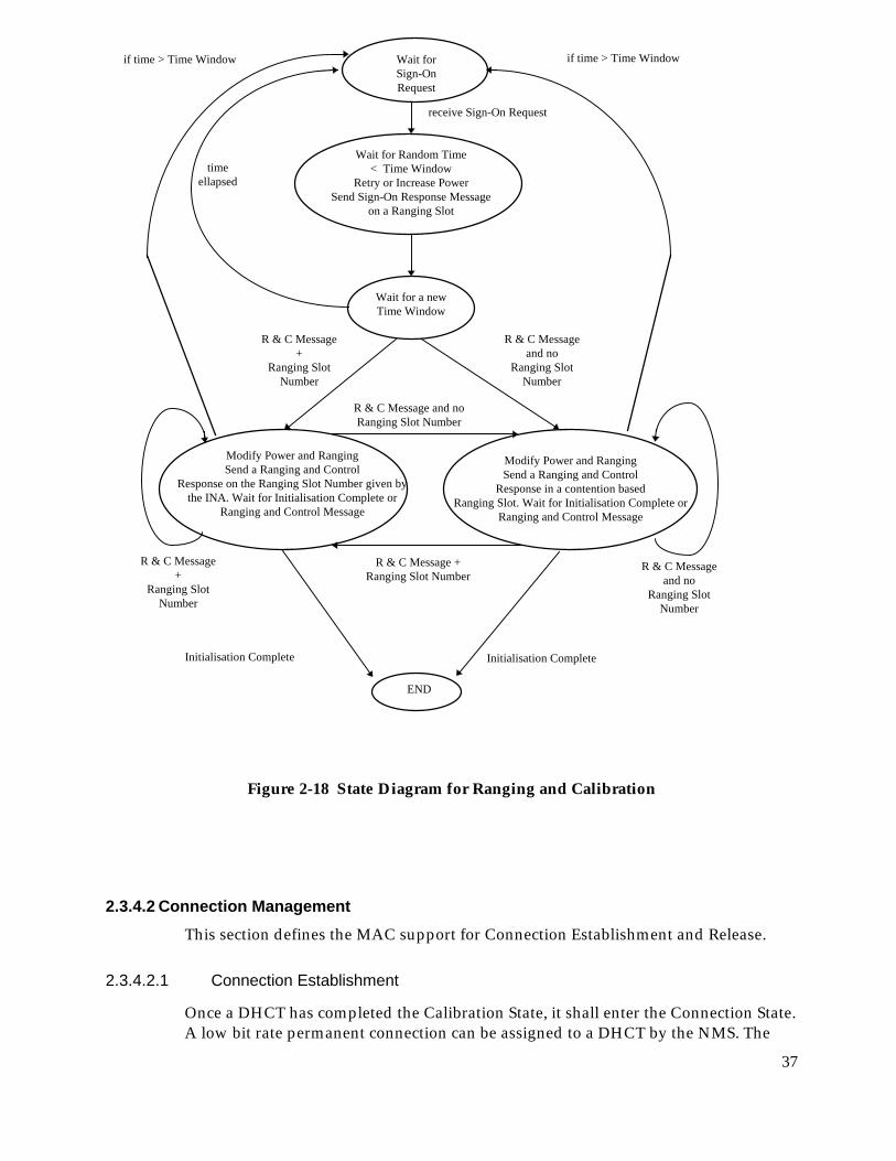
The DHCT shall Sign On via the Sign-On Procedure. A state diagram for Rangingand Calibration is given in Figure 2-18 The signaling flow for Sign-On is shown inFigure 2-17 and described below. Reception Indicators shall be ignored during theSign-On and Calibration process.
1. The DHCT shall tune to the downstream Provisioning channel and theupstream service channel with the information provided in the Initializationand Provisioning sequence.
2. The DHCT shall await the <MAC> Sign-On Request Message from theNetwork Related Control Entity. The DHCT shall utilize Contention basedentry on the service channel to access the network.
<MAC> DefaultConfiguration Message
<MAC> ProvisioningChannel Message
NRC NIU/STB

36
3. Upon receiving the <MAC> Sign-On Request Message, the DHCT shallrespond with the <MAC> Sign-On Response Message. The Sign-OnResponse Message shall be transmitted on a Ranging Control Slot.
4. The NMS, upon receiving the Sign-On Response Message shall validate theDHCT and send the <MAC> Ranging and Power Calibration Message.
5. The DHCT shall respond to the <MAC> Ranging and Power CalibrationMessage with the <MAC> Ranging and Power Calibration ResponseMessage. The <MAC> Ranging and Power Calibration Response Messageshall be transmitted on a Ranging Control Slot.
6. The NMS shall send the <MAC> Initialization Complete Message when theDHCT is calibrated. The DHCT is assumed to be calibrated if the messagearrives within a window of 1.5 symbols (upstream rate) and a power within awindow of 1.5 dB from their optimal value.
Figure 2-17 Sign-On Messaging Sequence
<MAC> Sign-OnResponse Message
<MAC> Ranging andPower Calibration
Message
<MAC> InitializationComplete Message
<MAC> Sign-OnRequest Message
NRC NIU/STB
<MAC> Ranging andPower CalibrationResponse Message
37
Figure 2-18 State Diagram for Ranging and Calibration
2.3.4.2 Connection ManagementThis section defines the MAC support for Connection Establishment and Release.
2.3.4.2.1 Connection Establishment
Once a DHCT has completed the Calibration State, it shall enter the Connection State.A low bit rate permanent connection can be assigned to a DHCT by the NMS. The
Wait forSign-OnRequest
Wait for Random Time< Time Window
Retry or Increase PowerSend Sign-On Response Message
on a Ranging Slot
Wait for a newTime Window
Modify Power and RangingSend a Ranging and Control
Response in a contention basedRanging Slot. Wait for Initialisation Complete or
Ranging and Control Message
Modify Power and RangingSend a Ranging and Control
Response on the Ranging Slot Number given bythe INA. Wait for Initialisation Complete or
Ranging and Control Message
END
receive Sign-On Request
R & C Message and noRanging Slot Number
R & C Message +Ranging Slot Number
Initialisation CompleteInitialisation Complete
R & C Messageand no
Ranging SlotNumber
R & C Message+
Ranging SlotNumber
timeellapsed
if time > Time Windowif time > Time Window
R & C Messageand no
Ranging SlotNumber
R & C Message+
Ranging SlotNumber

38
NMS can assign an upstream channel for contention or contentionless based access tothe network. In either case after the initial calibration procedure, the NMS provides aDefault Connection to the DHCT that the DHCT shall utilize to communicate to thenetwork. A given connection (identified by a Connection_ID) shall be assigned, atmost, a single VPI/VCI. The message flow for such Connection Establishment isshown in Figure 2-19 .
For all the traffic sent contention access, a collision is assumed if the appropriatereception indicator of the slot used for transmission is not set. A counter at theDHCT records the number, denoted by backoff_exponent, of collisions encounteredby a cell. The backoff_exponent counter starts from a value determined by theMin_Backoff_Exponent variable. The backoff_exponent is used to generate a uniformrandom number between 1 and 2^backoff_exponent. This random number is used toschedule retransmission of the collided cell. In particular, the random numberindicates the number of contention access slots the DHCT shall wait before ittransmits. The first transmission is carried out in a random cell within the contentionbased access region. If the counter reaches the maximum number, determined by theMax_Backoff_Exponent variable, the value of the counter remains at this valueregardless of the number of subsequent collisions. After a successful transmissionthe backoff_exponent counter is reset to a value determined by theMin_Backoff_Exponent variable.
In addition to the simple connect and release messages used to establish and removeconnections, the MAC message set provides two additional messages to handledynamic reallocation of bandwidth and channels. The Transmission Control Messageand the Reprovision Message provide the ability to redefine the parameters of eachconnection individually or as group.
The existing messages allow reallocation of resources on the network for anindividual DHCT. For example, the existing connections for a single DHCT may beremoved, the channel changed, and new connections reestablished to the existingsessions. The Reprovision Message allows for modification of the current connectionparameters including channel assignment. Gross reallocation of bandwidth orchannels is provided by moving all connections from one channel to another channelat once. The Transmission Control Message provides a method to rapidly change thechannel frequencies and other associated parameters for a single DHCT or all DHCTsassigned to a given channel.
1. After Initialization, Provisioning and Sign On Procedures are complete, the NMSshall assign a default upstream and downstream connection to the DHCT. Thisconnection can be assigned on any of the upstream channels except the upstreamservice channel ranging area. The DHCT shall assign the default connection bysending the <MAC> Connect Message to the DHCT. This message shall containthe upstream connection parameters and downstream frequency on which thedefault connection is to reside.

39
2. The DHCT, upon receiving the <MAC> Connect Message shall tune to therequired upstream and downstream frequencies and send the <MAC> ConnectResponse Message confirming receipt of the message.
1. Upon receipt of the <MAC> Connect Message, the NMS shall confirm the newconnection to proceed by sending the <MAC> Connect Confirm Message.
Figure 2-19 Connection Establishment Signaling Sequence
Different access modes are provided to the DHCT within access regions specified byinformation contained in the slot boundary fields of the downstream superframes.The limits between access regions allow users to know when to send data oncontention without risks of collision with contentionless type data. The followingrules define how to select access modes:
• Data connections:
When the NMS assigns a connection ID to the DHCT, it either specifies a slot list tobe used (Contentionless access) or the DHCT shall use contention or reserved accessby following this algorithm:
When the DHCT must send more cells than what was assigned by the NMS, itcan use contention access only if the number of cells to transmit is less thanMaximum_contention_access_message_length (specified in the MAC ConnectMessage from the NMS). In that case, it must wait for the slot reception indicatorbefore it is allowed to send other cells with the same VPI/VCI value. The DHCTcan send one request for reservation access if the number of cells is less thanMaximum_reservation_access_message_length (specified in the MAC ConnectMessage from the NMS). If more cells must be transmitted, the DHCT must sendmultiple requests for reservation access.
<MAC> ConnectResponse Message
<MAC> ConnectConfirm Message
<MAC> ConnectMessage
NRC NIU/STB

40
• MAC messages:
MAC messages can be sent on contention access or reservation access. MACmessages sent upstream must be less than 40 bytes long. If the MAC informationexceeds 40 bytes, it must be segmented into multiple 40 bytes independent MACmessages. Ranging access can only be used for specific MAC messages.
The following Upstream Access Types are defined:
• Contention Access
Contention Access indicates that data is sent in the slots assigned to thecontention access region in the upstream channel. It can be used either to send MACmessages or data. The VPI, VCI of the ATM cells are used to determine theconnection, type and direction of the data of higher layers. Contention based accessprovides instant channel allocation for the DHCT. The Contention based technique isused for multiple subscribers that will have equal access to the channel. Sincesimultaneous transmissions will occur, a positive acknowledgment of reception bythe NMS is sent in the reception indicator field of the OOB downstream channel. Acollision will be assumed if an DHCT does not receive a positive acknowledgment.
• Contentionless Access
Contentionless_Access indicates that data is sent in slots assigned to theContentionless based access region in the upstream channel. These slots are uniquelyassigned to a connection by the NMS.
• Reservation Access
Reservation Access implies that data is sent in the slots assigned to the reservationregion in the upstream channel. These slots are uniquely assigned on a frame byframe basis to a connection by the NMS. This assignment is made at the request ofthe DHCT for a given connection.
• Ranging Access
Ranging Access indicates that the data is sent in a slot preceded and followed byslots not used by other users. These slots allow users to adjust their clock dependingon their distance to the NMS such that their slots fall within the correct allocatedtime. The Ranging Access area is either in the Contention Access region or in slotsassigned to the reservation region in the upstream channel. The reservation slots areuniquely assigned on a frame by frame basis to the DHCT.
2.3.4.2.2 Connection Release
This section defines the MAC signaling requirements for connection release. Figure 2-20 below displays the signaling flow for releasing a connection.

41
1. Upon receiving the <MAC> Release Message from the NMS, the DHCT shalltear down the indicated upstream connections.
1. Upon tear down of the upstream connection, the DHCT shall send the <MAC>Release Response Message on the upstream frequency currently being used bythe DHCT for MAC Messages.
Figure 2-20 Connection Release Signaling
2.3.4.3 MAC Link ManagementThe MAC Link Management tasks provide continuous monitoring and optimizationof upstream resources. These functions include:
• Power and Timing Management
• TDMA Allocation Management
• Reservation Allocation Management
• Channel Error Management
2.3.4.3.1 Power and Timing Management
Power and Timing Management shall provide continuous monitoring of upstreamtransmission from the DHCT. The <MAC> Ranging and Power CalibrationMessage is used to maintain a DHCT within predefined thresholds of power andtime.
The Upstream Burst Demodulator shall continuously monitor the upstream bursttransmissions from an DHCT. Upon detection of an DHCT outside the predefinedrange, the NMS shall send the <MAC> Ranging and Power Calibration Message tothe DHCT.
2.3.4.3.2 TDMA Allocation Management
To ensure optimum assignment of TDMA resources, the NMS shall ensure theupstream allocation of TDMA resources for various connections remain intact when
<MAC> ReleaseResponse Message
<MAC> ReleaseMessage
NRC NIU/STB

42
allocating resources to a new connection. However, in the event that reconfigurationis required to minimize fragmentation of resources, then the NMS shall dynamicallyreconfigure the upstream TDMA assignments to a DHCT or group of DHCT. The<MAC> Reprovision Message is utilized to change previously establishedconnection parameters.
2.3.4.3.3 Channel Error Management
During periods of connection inactivity, the DHCT shall enter an Idle Mode. Idlemode is characterized by periodic transmission by the DHCT of a <MAC> IdleMessage. The Idle Mode transmission shall occur at a periodic rate sufficient for theNMS to establish Packet Error Rate statistics.
2.3.4.4 MAC Message DefinitionsFor all MAC messages where the parameter length is smaller than the field, theparameter shall be right justified with leading bits set to 0.
All reserved fields in the MAC messages shall be set to 0.
2.3.4.4.1 Initialization, Provisioning and Sign On Messages
This section provides a detailed definition of the MAC messages for Initialization,Provisioning and Sign-On procedures.
2.3.4.4.1.1 <MAC> Provisioning Channel Message
The <MAC> PROVISIONING CHANNEL MESSAGE is sent by the NMS to directthe DHCT to the proper Out of Band frequency where provisioning is performed.The format of the message is shown below.
Provisioning_Channel_Message(){ Bits Bytes Bit Number/Description
Provisioning_Channel_Control_Field 1Reserved 7 7..1Provisioning_Frequency_Included 1 0:{no, yes}
if (Provisioning_Channel_Control_Field ==Provisioning_Frequency_Included) {
Provisioning_Frequency 32 4Downstream_Type 8 1 {enum}
}}
Provisioning Channel Control Field
Provisioning_Channel_Control_Field is used to specify the downstreamfrequency where the DHCT will be provisioned.

43
Provisioning Frequency Included
Provisioning_Frequency_Included is a Boolean when set, indicates that adownstream OOB frequency is specified that the DHCT should tune to begin theprovisioning process. When cleared, indicates that the current downstream frequencyis the provisioning frequency.
Provisioning Frequency
Provisioning_Frequency is a 32-bit unsigned integer representing the Out ofBand Frequency in which DHCT provisioning occurs. The unit of measure is Hz.
Downstream Type
Downstream_Type is an 8-bit enumerated type indicating the modulation format forthe downstream connection.
enum Downstream_Type { Reserved,QPSK_1.544,QPSK_3.088,Reserved 3..255 };
2.3.4.4.1.2 <MAC> Default Configuration Message
The <MAC> DEFAULT CONFIGURATION MESSAGE is sent by the NMS to theDHCT. The message provides default parameter and configuration information tothe DHCT. The format of the message is shown below
Default_Configuration_Message(){ Bits Bytes Bit Number /Description
Regs_Incr_Pwr_Retry_Count 8 1Service_Channel_Frequency 32 4Service_Channel_Control_Field 1
MAC_Flag_Set 5 7..3Service_Channel 3 2..0
Backup_Service_Channel_Frequency 32 4Backup_Service_Channel_Control_Field 1
Backup_MAC_Flag_Set 5 7..3Backup_Service_Channel 3 2..0
Service_Channel_Frame_Length 16 2Service_Channel_Last_Slot 13 2Max_Power_Level 8 1Min_Power_Level 8 1Upstream_Transmission_Rate 3 1 {enum}Max_Backoff_Exponent 8 1Min_Backoff_Exponent 8 1Idle_Interval 16 2
}

44
Sign-On Increment Power Retry Count
Regs_Incr_Pwr_Retry_Count is an 8-bit unsigned integer representing thenumber of attempts the DHCT should try to enter the system at the same power levelbefore incrementing its power level.
Service Channel Frequency
Service_Channel_Frequency is a 32 bit unsigned integer representing theupstream frequency assigned to the service channel. The unit of measure is in Hz.
MAC_Flag_Set
MAC_Flag_Set is a 5 bit field indicating the MAC Flag set number assigned to theservice channel (i.e. R1a, R1b and R1c represent MAC Flag set 1). It can take thevalues 1..16. Values 0 and 17..31 are invalid.
A downstream channel contains control information for each of its associatedupstream channels. This information is contained within structures known as MACFlags. A set of MAC Flags, represented by either 24 bits (denoted b0..b23) or by 3bytes (denoted Rxa, Rxb and Rxc), are uniquely assigned to a given upstreamchannel. Refer to section 2.1.9 for a definition of the MAC Flags.
In the OOB downstream case, each SL-ESF frame structure contains eight sets ofMAC Flags represented by Rxa, Rxb and Rxc, where x is replaced by the numbers1..8. In the case of a 1.544 Mbit/s downstream bit rate, only one SL-ESF frame occursduring a 3 ms interval providing 8 sets of MAC Flags. In the case of a 3.088 Mbit/sdownstream bit rate, two SL-ESF frames occur during a 3 ms interval, providing 16sets of MAC Flags. The second set of MAC Flags (contained in the second SL-ESF) aredenoted by Rxa, Rxb and Rxc, where x is replaced by the numbers 9 through 16.
In case of a 3.088 Mbit/s upstream channel, two sets of MAC Flags are required. Inthis case, the MAC_Flag_Set parameter represents the first of two successivelyassigned MAC Flag sets.
Service Channel
Service_Channel is a 3-bit field which defines the channel assigned to theService_Channel_Frequency. Although the function provided by this parameter issuperseded in the DAVIC 1.2 specification by the MAC_Flag_Set, it is retained inorder to identify the logical channel assigned to the DHCT.
Backup Service Channel Frequency
Backup_Service_Channel_Frequency is a 32 bit unsigned integer representingthe upstream frequency assigned to the backup service channel. The backup servicechannel is used when entry on the primary service channel fails. The unit of measureis in Hz.
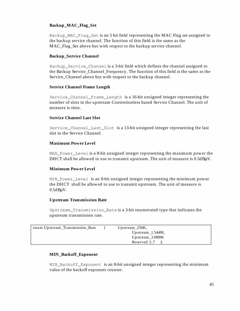
45
Backup_MAC_Flag_Set
Backup_MAC_Flag_Set is an 5 bit field representing the MAC Flag set assigned tothe backup service channel. The function of this field is the same as theMAC_Flag_Set above but with respect to the backup service channel.
Backup_Service Channel
Backup_Service_Channel is a 3-bit field which defines the channel assigned tothe Backup Service_Channel_Frequency. The function of this field is the same as theService_Channel above but with respect to the backup channel.
Service Channel Frame Length
Service_Channel_Frame_Length is a 16-bit unsigned integer representing thenumber of slots in the upstream Contentionless based Service Channel. The unit ofmeasure is slots.
Service Channel Last Slot
Service_Channel_Last_Slot is a 13-bit unsigned integer representing the lastslot in the Service Channel.
Maximum Power Level
MAX_Power_Level is a 8-bit unsigned integer representing the maximum power theDHCT shall be allowed to use to transmit upstream. The unit of measure is 0.5dBµV.
Minimum Power Level
MIN_Power_Level is an 8-bit unsigned integer representing the minimum powerthe DHCT shall be allowed to use to transmit upstream. The unit of measure is0.5dBµV.
Upstream Transmission Rate
Upstream_Transmission_Rate is a 3-bit enumerated type that indicates theupstream transmission rate.
enum Upstream_Transmission_Rate { Upstream_256K,Upstream_1.544M,Upstream_3.088MReserved 3..7 };
MIN_Backoff_Exponent
MIN_Backoff_Exponent is an 8-bit unsigned integer representing the minimumvalue of the backoff exponent counter.

46
MAX_Backoff_Exponent
MAX_Backoff_Exponent is an 8-bit unsigned integer representing the minimumvalue of the backoff exponent counter.
Idle_Interval
Idle_Interval is a 16-bit unsigned integer representing the predefined intervalfor the MAC Idle Messages. The unit of the measure is in milliseconds.
2.3.4.4.1.3 <MAC> Sign-On Request Message
The <MAC> SIGN-ON REQUEST message is issued periodically by the NMS toallow a DHCT to indicate its presence in the network. The format of thissubcommand is shown below. The Sign_On_Request_Message is ignored by theDHCT unless it is in the sign-on mode.
Sign-On_Request_Message(){ Bits Bytes Bit Number/Description
Sign-On_Control_Field 8 1Reserved 7 7-1Address_Filter_Params_Included 1 0 : {no, yes}
Response_Collection_Time_Window 16 2if (Sign-On_Control_Field==
Address_Filter_Params_Included){Address_Position_Mask (8) (1)Address_Comparison_Value (8) (1)
}}
Sign-On Control Field
Sign-On_Control_Field specifies what parameters are included in the SIGN-ONREQUEST
Address Filter Parameters Included
address_filter_params_included is a Boolean, when set, indicates that theDHCT should respond to the SIGN-ON REQUEST only if its address matches thefilter requirements specified in the message.
Response Collection Time Window
Response_Collection_Time_Window is a 16-bit unsigned integer that specifiesthe duration of time the DHCT has to respond to the SIGN-ON REQUEST. The unitof measure is msec.
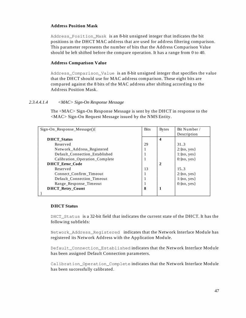
47
Address Position Mask
Address_Position_Mask is an 8-bit unsigned integer that indicates the bitpositions in the DHCT MAC address that are used for address filtering comparison.This parameter represents the number of bits that the Address Comparison Valueshould be left shifted before the compare operation. It has a range from 0 to 40.
Address Comparison Value
Address_Comparison_Value is an 8-bit unsigned integer that specifies the valuethat the DHCT should use for MAC address comparison. These eight bits arecompared against the 8 bits of the MAC address after shifting according to theAddress Position Mask.
2.3.4.4.1.4 <MAC> Sign-On Response Message
The <MAC> Sign-On Response Message is sent by the DHCT in response to the<MAC> Sign-On Request Message issued by the NMS Entity.
Sign-On_Response_Message(){ Bits Bytes Bit Number /Description
DHCT_Status 4Reserved 29 31..3Network_Address_Registered 1 2:{no, yes}Default_Connection_Established 1 1:{no, yes}Calibration_Operation_Complete 1 0:{no, yes}
DHCT_Error_Code 2Reserved 13 15..3Connect_Confirm_Timeout 1 2:{no, yes}Default_Connection_Timeout 1 1:{no, yes}Range_Response_Timeout 1 0:{no, yes}
DHCT_Retry_Count 8 1}
DHCT Status
DHCT_Status is a 32-bit field that indicates the current state of the DHCT. It has thefollowing subfields:
Network_Address_Registered indicates that the Network Interface Module hasregistered its Network Address with the Application Module.
Default_Connection_Established indicates that the Network Interface Modulehas been assigned Default Connection parameters.
Calibration_Operation_Complete indicates that the Network Interface Modulehas been successfully calibrated.
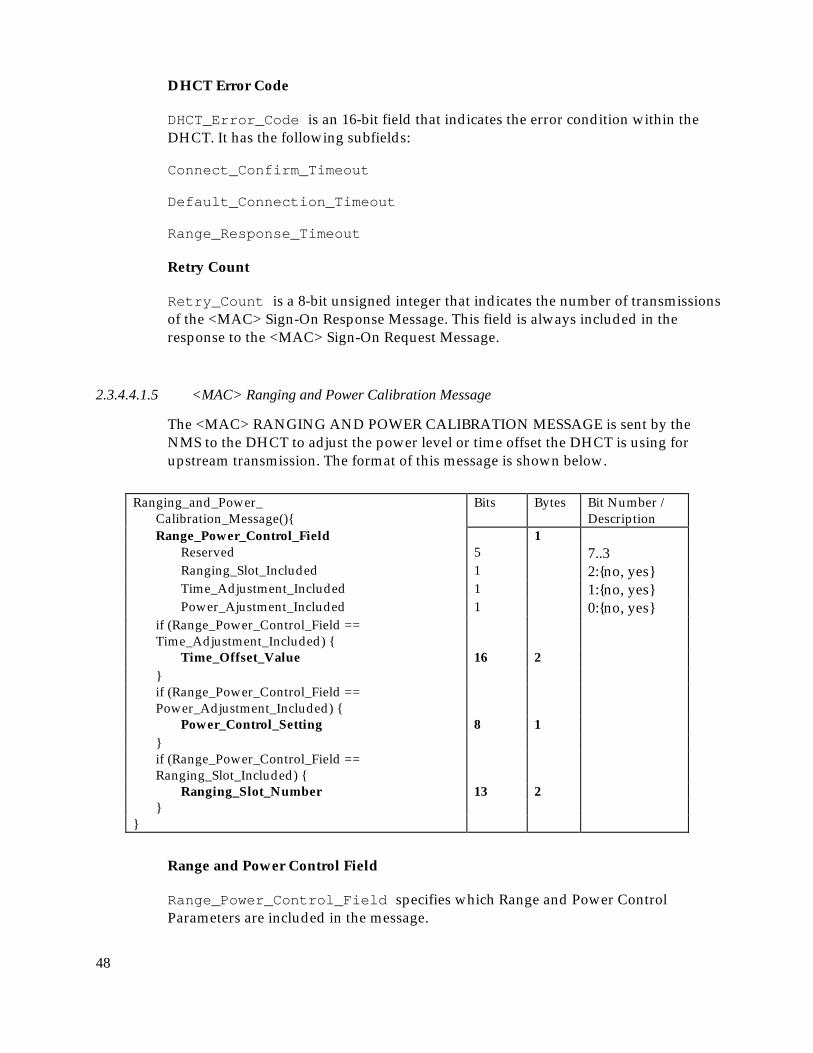
48
DHCT Error Code
DHCT_Error_Code is an 16-bit field that indicates the error condition within theDHCT. It has the following subfields:
Connect_Confirm_Timeout
Default_Connection_Timeout
Range_Response_Timeout
Retry Count
Retry_Count is a 8-bit unsigned integer that indicates the number of transmissionsof the <MAC> Sign-On Response Message. This field is always included in theresponse to the <MAC> Sign-On Request Message.
2.3.4.4.1.5 <MAC> Ranging and Power Calibration Message
The <MAC> RANGING AND POWER CALIBRATION MESSAGE is sent by theNMS to the DHCT to adjust the power level or time offset the DHCT is using forupstream transmission. The format of this message is shown below.
Ranging_and_Power_Calibration_Message(){
Bits Bytes Bit Number /Description
Range_Power_Control_Field 1Reserved 5 7..3Ranging_Slot_Included 1 2:{no, yes}Time_Adjustment_Included 1 1:{no, yes}Power_Ajustment_Included 1 0:{no, yes}
if (Range_Power_Control_Field ==Time_Adjustment_Included) {
Time_Offset_Value 16 2}if (Range_Power_Control_Field ==Power_Adjustment_Included) {
Power_Control_Setting 8 1}if (Range_Power_Control_Field ==Ranging_Slot_Included) {
Ranging_Slot_Number 13 2}
}
Range and Power Control Field
Range_Power_Control_Field specifies which Range and Power ControlParameters are included in the message.

49
Time Adjustment Included
Time_Adjustment_Included is a Boolean when set, indicates that a relative TimeOffset Value is included that the DHCT should use to adjust its upstreamContentionless based transmission.
Power Adjust Included
Power_Adjust_Included is a Boolean when set, indicates that a relative PowerControl Setting is included in the message
Ranging Slot Included
Ranging_Slot_Included is a Boolean when set, indicates the calibration slot isincluded in the message.
Time Offset Value
Time_Offset_Value is a 16-bit short integer representing a relative offset of theupstream transmission timing. A negative value indicates an adjustment forward intime. A positive value indicates an adjustment back in time. The unit of measure is100 nsec.
Power Control Setting
Power_Control_Setting is an 8-bit signed integer to be used to set the newupstream power level of the DHCT. A positive value represents an increase of theoutput power level.
new output_power_level = current output_power_level + power_control_setting*0.5dB
Ranging Slot Number
Ranging_Slot_Number is a 13-bit unsigned integer that represents the slot numberassigned for ranging the DHCT. It shall be assigned by the NMS in the reservationarea. The NCR shall assure that an unassigned slot precedes and follows the rangingslot.
2.3.4.4.1.6 <MAC> Ranging and Power Calibration Response Message
The <MAC> RANGING AND POWER CALIBRATION RESPONSE Message is sentby the DHCT to the NMS in response to the <MAC> RANGING AND POWERCALIBRATION MESSAGE. The format of the message is shown below.

50
Ranging_Power_Response_Message(){ Bits Bytes Bit Number /Description
Power_Control_Setting 8 1}
Power Control Setting
Power_Control_Setting is an 8-bit unsigned integer representing the actualpower used by the DHCT for upstream transmission. The unit of measure is 0.5dBµV.
2.3.4.4.1.7 Initialization Complete Message
The <MAC> INITIALIZATION COMPLETE Message is sent by the NMS to theDHCT to indicate the end of the MAC Sign-On and Provisioning procedure. TheDHCT shall be disabled after receiving a non-zero Completion_Status_Field value.
Initialization_Complete_Message(){ Bits Bytes Bit Number /Description
Completion_Status_Field 1Reserved 4 7..4Invalid_DHCT 1 3:{no, yes}Timing_Ranging_Error 1 2:{no, yes}Power_Ranging_Error 1 1:{no, yes}Transmitter_Error 1 0:{no, yes}
}
Completion_Status_Field
Completion_Status_Field is an 8-bit field that indicates errors in theinitialization phase. It has the following subfields:
Invalid_DHCT is a boolean that (when set to 1) indicates that the DHCT isinvalid.
Timing_Ranging_Error is a boolean that (when set to 1) indicates that theranging has not succeeded.
Power_Ranging_Error is a boolean that (when set to 1) indicates that thepower ranging has not succeeded.
Transmitter_Error is a boolean that (when set to 1) indicates a transmittererror.
2.3.4.4.2 Connection Management Messages
This section defines the MAC messages for connection establishment and release.

51
2.3.4.4.2.1 <MAC> Connect Message
Connect_Message (){ Bits Bytes Bit Number /Description
Connection_ID 32 4Session_Number 32 4Resource_Number 16 2Connection_Control_Field 1
DS_ATM_CBD_Included 1 7: {no, yes}DS_MPEG_CBD_Included 1 6:{no, yes}US_ATM_CBD_Included 1 5:{no, yes}Upstream_Channel_Number 3 4..2Slot_List_Included 1 1:{no, yes}Cyclic_Assignment 1 0:{no, yes}
Frame_Length 16 2Maximum_Contention_Access_
Message_Length8 1
Maximum_Reservation_Access_Message_Length
8 1
if (Connection_Control_Field ==DS_ATM_CBD_Included) {
Downstream_ATM_CBD() 64 8}if (Connection_Control_Field ==
DS_MPEG_CBD_Included) {Downstream_MPEG_CBD() 48 6
}if (Connection_Control_Field ==
US_ATM_CBD_Included) {Upstream_ATM_CBD() 64 8
}if (Connection_Control_Field ==
Slot_List_Included) {Number_Slots_Defined 8 1for(i=0; i<Number_Slots_Assigned; i++){
Slot_Number 13 2}
}if (Connection_Control_Field ==
Cyclic_Assignment) {Contentionless_Start 16 2Contentionless_Dist 16 2
Number_Cycle_Slots_Defined 16 2}
}

52
Connection ID
Connection_ID is a 32-bit unsigned integer representing a connection Identifierfor the DHCT Dynamic Connection.
Session Number
Session_Number is a 32-bit unsigned integer representing the Session that theconnection parameters are associated.
Resource Number
Resource_Number is a 16-bit unsigned integer providing a unique number to theresource defined in the message.
Connection Control Field
DS_ATM_CBD_Included is a boolean that indicates that the Downstream ATMDescriptor is included in the message.
DS_MPEG_CBD_Included is a boolean that indicates that the Downstream MPEGDescriptor is included in the message.
US_ATM_CBD_Included is a boolean that indicates that the Upstream ATMDescriptor is included in the message.
Upstream_Channel_Number is a 3-bit unsigned integer that provides an identifierfor the upstream channel.
Slot_List_Included is a boolean that indicates that the Slot List is included inthe message.
Cyclic_Assignment is a boolean that indicates Cyclic Assignment.
Frame Length
Frame_Length is a 16 bit unsigned number represents the number of successiveslots in the contentionless access region that associated with each contentionless slotassignment. In the slot_list method of allocating slots it represents the number ofsuccessive slots associated with each element in the list. In the cyclic method ofallocating slots it represents the number of successive slots associated with theContentionless_Start_Slot and those which are multiples of Contentionless_Distancefrom the Contentionless_Start_Slot.

53
Maximum Contention Access Message Length
Maximum_Contention_Access_Message_Length is an 8 bit numberrepresenting the maximum length of a message in ATM sized cells that may betransmitted using contention access. Any message greater than this should usereservation access.
Maximum Reservation Access Message Length
Maximum_Reservation_Access_Message_Length is an 8 bit numberrepresenting the maximum length of a message in ATM sized cells that may betransmitted using a single reservation access. Any message greater than this shouldbe transmitted by making multiple reservation requests.
Downstream ATM Connection Block Descriptor
Downstream_ATM_CBD(){ Bits Bytes Bit Number /Description
Downstream_Frequency 32 4Downstream_VPI 8 1Downstream_VCI 16 2Downstream_Type 8 1 {enum}
}
Downstream_Frequency is a 32-bit unsigned integer representing the Frequencywhere the connection resides. The unit of measure is in Hz.
Downstream_VPI is an 8-bit unsigned integer representing the ATM Virtual PathIdentifier that is used for downstream transmission over the Dynamic Connection.
Downstream_VCI is an 16-bit unsigned integer representing the ATM VirtualChannel Identifier that is used for downstream transmission over the DynamicConnection.
Downstream_Type is an 8-bit enumerated type indicating the modulation format forthe downstream connection.
enum Downstream_Type { QAM,QPSK_1.544,QPSK_3.088,Reserved 3..255 };

54
Downstream MPEG Connection Block Descriptor
Downstream_CBD_MPEG(){ Bits Bytes Bit Number /Description
Downstream_Frequency 32 4Program Number 16 2
}
Downstream_Frequency is a 32-bit unsigned integer representing the Frequencywhere the connection resides. The unit of measure is in Hz.
Program_Number is a 16-bit unsigned integer uniquely referencing the downstreamvirtual connection assignment.
Upstream ATM Connection Block Descriptor
Upstream_ATM_CBD () { Bits Bytes Bit Number /Description
Upstream_Frequency 32 4Upstream_VPI 8 1Upstream_VCI 16 2Upstream_Parameters 1
MAC_Flag_Set 5 7..3Upstream_Rate 3 2..0:{enum}
}
Upstream_Frequency is a 32-bit unsigned integer representing the channel onassigned to the connection. The unit of measure is in Hz.
Upstream_VPI is an 8-bit unsigned integer representing the ATM Virtual PathIdentifier that is used for upstream transmission over the Dynamic Connection.
Upstream_VCI is an 16-bit unsigned integer representing the ATM Virtual ChannelIdentifier that is used for upstream transmission over the Dynamic Connection.
MAC_Flag_Set is an 5 bit field representing the MAC Flag set assigned to theconnection. In the OOB downstream SL-ESF frame payload structure, each set ofthree bytes, denoted by Rxa- Rxc, comprise a flag set. These eight flag sets areassigned the numbers 0..7. In the case of a 3.088 Mbit/s upstream channel, twosuccessive flag sets are required to define a 3ms period. In this case, this parameterrepresents the first of two successively assigned flag sets. In the case of a3.088Mbit/s OOB downstream, two successive SL-ESF frames define the 3msinterval. The Rxa-Rxc bytes of the first frame represent flag sets 0..7 while the Rxa-Rxc bytes of the second frame represent flag sets 8..15.

55
enum Upstream_Rate { Upstream_256K,Upstream_1.544M,Upstream_3.088M,Reserved 3..7 };
Number of Slots Defined
Number_Slots_Defined is an 8-bit unsigned integer that represents the numberof slot assignments contained in the message. The unit of measure is slots.
Slot Number
Slot_Number is a 13-bit unsigned integer that represents the Contentionless basedSlot Number assigned to the DHCT.
Contentionless Start
Contentionless_Start is a 16 bit unsigned integer that represents the startingupstream slot within the contentionless access region that is assigned to the DHCT.The DHCT may use the next Frame_Length slots of the contentionless access regions.
Contentionless Distance
Contentionless_Distance is 16 bit unsigned integer that represents the distancein upstream slots between additional slots assigned to the DHCT. The DHCT isassigned all slots that are a multiple of Contentionless_Distance from theContentionless_Start_Slot within the contentionless access region. The DHCT mayuse the next Frame_Length slots of the contentionless access regions from each ofthese additional slots.
Number Cyclic Slots Defined
Number_Cyclic_Slots Defined is a 16 bit unsigned integer that represents the numberof slots assigned by the message. The unit of measure is in assigned slots.
2.3.4.4.2.2 <MAC> Connect Response Message
The <MAC> CONNECT RESPONSE MESSAGE is sent to the NMS from the DHCTin response to the <MAC> CONNECT MESSAGE. The message shall be transmittedon the upstream frequency specified in the <MAC> CONNECT MESSAGE.
Connect_Response_Message(){ Bits Bytes Bit Number /Description
Connection_ID 32 4}

56
Connection ID
Connection_ID is a 32-bit unsigned integer representing a global connectionIdentifier for the DHCT Dynamic Connection.
2.3.4.4.2.3 <MAC> Connect Confirm Message
The <MAC> Connect Confirm message is sent from the NMS to the DHCT. Its usageis recommended when NMS validation of new connection is required.
Connect_Confirm_Message(){ Bits Bytes Bit Number /Description
Connection_ID 32 4}
Connection ID
Connection_ID is a 32-bit unsigned integer representing a global connectionIdentifier for the DHCT Dynamic Connection.
2.3.4.4.2.4 <MAC> Reservation Request Message
Reservation_Request_Message (){ Bits Bytes Bit Number /Description
Reservation_ID 16 2Reservation_Request_Slot_Count 8 1
}
Reservation_ID
Reservation_ID is a 16 bit unsigned number representing a locally assignedidentifier for the connection. This is used as a short identifier by the DHCT toidentify the appropriate Reservation_Grant_Messages.
Reservation_Request_Slot_Count
Reservation_Request_Slot_Count is an 8 bit unsigned number representingthe number of slots requested by the DHCT. This is the number of sequential slotsthat will be allocated in the reservation region of the upstream channel. The NMSwill respond with the Reservation_Acknowledge_Message granting the request.

57
2.3.4.4.2.5 <MAC> Reservation Grant Message
The <MAC> RESERVATION GRANT MESSAGE is used to indicate to the DHCTwhich slots have been allocated in response to the Reservation_Request_Message.The DHCT identifies its entry in the Reservation_Grant_Message by comparing theReservation_ID assigned to it by the Reservation_ID_Assignment_Message and theentries in the Reservation_Grant_Message.
The format of the message is given below.
Reservation_Grant_Message (){ Bits MnemonicReference_Slot 16 uimsbfNumber_Grants 8 uimsbffor (i=1;i<=Number_Grants;i++) {
Reservation_ID 16 uimsbfGrant_Slot_Count 4 uimsbfRemaining_Slot_Count 5 uimsbfGrant_Control 2 uimsbfGrant_Slot_Offset 5 uimsbf
}}
Reference_slot
Reference_slot is an 16 bit unsigned number indicating the reference point forthe remaining parameters of this message. This represents a physical slot of theupstream channel. Since the up-stream and down stream slots are not aligned, theNMS shall send this message in a downstream slot such that it is received by theDHCT before the Reference_Slot exists on the upstream channel.
Number_grants
Number_Grants is an 8 bit unsigned number representing the number of grantscontained within this message.
Reservation_ID
Reservation_ID is a 16 bit unsigned number representing a locally assignedidentifier for the connection. This is used as a short identifier by the DHCT toidentify the appropriate Reservation_Grant messages.
Grant_Slot_Count
Grant_Slot_Count is an 4 bit unsigned number representing the number ofsequential slots currently granted for the upstream burst. Upon receipt of thismessage the DHCT is assigned Grant_Slot_Count sequential slots in the reservationaccess region of the upstream channel starting at the position indicated by theReference_Slot and Grant_Slot_Offset values. A value of zero indicates that no slots
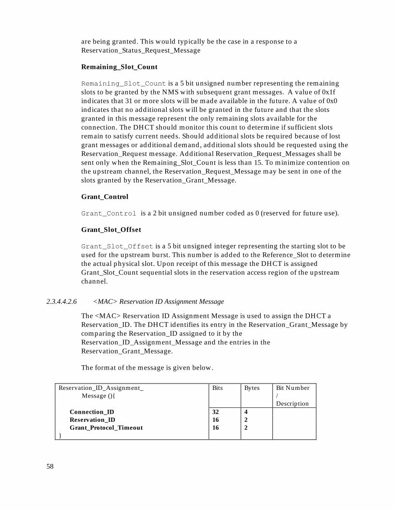
58
are being granted. This would typically be the case in a response to aReservation_Status_Request_Message
Remaining_Slot_Count
Remaining_Slot_Count is a 5 bit unsigned number representing the remainingslots to be granted by the NMS with subsequent grant messages. A value of 0x1findicates that 31 or more slots will be made available in the future. A value of 0x0indicates that no additional slots will be granted in the future and that the slotsgranted in this message represent the only remaining slots available for theconnection. The DHCT should monitor this count to determine if sufficient slotsremain to satisfy current needs. Should additional slots be required because of lostgrant messages or additional demand, additional slots should be requested using theReservation_Request message. Additional Reservation_Request_Messages shall besent only when the Remaining_Slot_Count is less than 15. To minimize contention onthe upstream channel, the Reservation_Request_Message may be sent in one of theslots granted by the Reservation_Grant_Message.
Grant_Control
Grant_Control is a 2 bit unsigned number coded as 0 (reserved for future use).
Grant_Slot_Offset
Grant_Slot_Offset is a 5 bit unsigned integer representing the starting slot to beused for the upstream burst. This number is added to the Reference_Slot to determinethe actual physical slot. Upon receipt of this message the DHCT is assignedGrant_Slot_Count sequential slots in the reservation access region of the upstreamchannel.
2.3.4.4.2.6 <MAC> Reservation ID Assignment Message
The <MAC> Reservation ID Assignment Message is used to assign the DHCT aReservation_ID. The DHCT identifies its entry in the Reservation_Grant_Message bycomparing the Reservation_ID assigned to it by theReservation_ID_Assignment_Message and the entries in theReservation_Grant_Message.
The format of the message is given below.
Reservation_ID_Assignment_Message (){
Bits Bytes Bit Number/Description
Connection_ID 32 4Reservation_ID 16 2Grant_Protocol_Timeout 16 2
}

59
Connection ID
Connection_ID is a 32-bit unsigned integer representing a global connectionidentifier for theDHCT Dynamic Connection.
Reservation_ID
Reservation_ID is a 16 bit unsigned number representing a locally assignedidentifier for the connection. This is used as a short identifier by the DHCT toidentify the appropriate Reservation_Grant_Messages.
Grant_Protocol_Timeout
Grant_Protocol_Timeout is a 16 bit unsigned number representing the time inmilliseconds that the DHCT should wait before verifying the status of pendinggrants. This parameter specifies the time that the DHCT should wait after sendingthe Reservation_Request Message or after receiving the lastReservation_Grant_Message, with an entry addressed to the DHCT containing anonzero Remaining_slot_count, before initiating a reservation status request. If theDHCT has pending grants and the timeout occurs, it should send theReservation_Status_Request_Message to the NMS. The NMS will respond with theReservation_Grant_Message (probably without granting any slots) to inform theDHCT of any remaining slots left to be granted. This allows the DHCT to correct anyproblems should they exist such as issuing an additional request for slots or waitingpatiently for additional grants.
2.3.4.4.2.7 <MAC> Reservation ID Response Message
The <MAC> Reservation ID Response Message is used to acknowledge the receipt ofthe <MAC> Reservation_ID_Assignment message.
The format of the message is given below.
Reservation_ID_Response_Message (){ Bits Bytes Bit Number/Description
Connection_ID 32 4Reservation_ID 16 2
}
Connection ID
Connection_ID is a 32-bit unsigned integer representing a global connectionidentifier for theDHCT Dynamic Connection.

60
Reservation_ID
Reservation_ID is a 16 bit unsigned number representing a locally assignedidentifier for the connection. This is used as a short identifier by the DHCT toidentify the appropriate Reservation_Grant_Messages.
2.3.4.4.2.8 <MAC> Reservation Status Request
The <MAC> RESERVATION STATUS REQUEST Message is used to determine thestatus of the outstanding grants to be assigned by the NMS. This message is only sentafter the Grant protocol timeout is exceeded. The NMS will respond with theReservation_Grant_Message (possibly without granting any slots) to inform theDHCT of any remaining slots left to be granted. This allows the DHCT to correct anyproblems should they exist such as issuing an additional request for slots or waitingpatiently for additional grants.
The format of the message is given below.
Reservation_Status_Request_Message (){ Bits Bytes Bit Number /Description
Reservation_ID 16 2Remaining_Request_Slot_Count 8 1
}
Reservation_ID
Reservation_ID is a 16 bit unsigned number representing a locally assignedidentifier for the connection. This is used as a short identifier by the DHCT toidentify the appropriate Reservation_Grant_Messages.
Remaining_Request_Slot_Count
Remaining_Request_Slot_Count is an 8 bit unsigned number representing thenumber of slots that the DHCT is expecting to be granted.
2.3.4.4.2.9 <MAC> Release Message
The <MAC> Release Message is sent from the NMS to the DHCT to terminate apreviously established connection.

61
Release_Message(){ Bits Bytes Bit Number /Description
Number_of_Connections 8 1for(i=0;i<Number_of_Connections;
i++){Connection_ID 32 4}
}
Number_of_Connections
Number_of_Connections is an 8-bit unsigned integer representing the number ofConnection Identifiers listed in the <MAC> Release Message.
Connection ID
Connection_ID is a 32-bit unsigned integer representing a global connectionIdentifier for the DHCT Dynamic Connection.
2.3.4.4.2.10 <MAC> Release Response Message
The <MAC> RELEASE RESPONSE MESSAGE is sent by the DHCT to the NMS toacknowledge the release of a connection. The format of the message is shown in theFigure.
Release_Response_Message (){ Bits Bytes Bit Number /Description
Connection_ID 32 4}
Connection ID
Connection_ID is a 32-bit unsigned integer representing the global connectionIdentifier used by the DHCT for this connection.
2.3.4.4.2.11 <MAC> Idle Message
The <MAC> Idle Message is sent by the DHCT within the DHCT to the NMS atpredefined intervals when upstream connection buffers are empty.
Idle_Message(){ Bits Bytes Bit Number /Description
Idle_Sequence_Count 8 1Power_Control_Setting 8 1
}

62
Idle Sequence Count
Idle_Sequence_Count is a 8-bit unsigned integer representing the count of<MAC> IDLE MESSAGES transmitted while the DHCT is Idle.
Power Control Setting
Power_Control_Setting is a 8-bit unsigned integer representing the absolutepower attenuation that the DHCT is using for upstream transmission.
2.3.4.4.3 Link Management Messages
2.3.4.4.3.1 <MAC> Transmission Control Message
The <MAC> TRANSMISSION CONTROL MESSAGE is sent to the DHCT from theNMS to control several aspects of the upstream transmission. This includes stoppingupstream transmission, reenabling transmission from a DHCT or group of DHCTsand rapidly changing the upstream frequency being used by a DHCT or group ofDHCTs. To identify a group of DHCTs for switching frequencies, the <MAC>TRANSMISSION CONTROL MESSAGE is sent in broadcast mode with theOld_Frequency included in the message. When broadcast with theOld_Frequency, the DHCT shall compare its current frequency value toOld_Frequency. When equal, the DHCT shall switch to the new frequencyspecified in the message. When not equal, the DHCT shall ignore the new frequencyand remain on its current channel.

63
Transmission_Control_Message(){ Bits Bytes Bit Number /Description
Transmission_Control_Field 1Reserved 3 7..5Stop_Upstream_Transmission 1 4:{no, yes}Start_Upstream_Transmission 1 3:{no, yes}Old_Frequency_Included 1 2:{no, yes}Switch_Downstream_OOB_Frequency 1 1:{no, yes}Switch_Upstream_Frequency 1 0:{no, yes}
if (Transmission_Control_Field ==Switch_Upstream_Frequency &&Old_Frequency_Included) {
Old_Upstream_Frequency 32 4}if (Transmission_Control_Field ==Switch_Upstream_Frequency) {
New_Upstream_Frequency 32 4New_Upstream_Parameters 2
New_Upstream_Channel_Number 3 7..5Reserved 2 4..3Upstream_Rate 3 2..0:{enum}MAC_Flag_Set 5 7..3Reserved 3 2..0
}if (Transmission_Control_Field ==Switch_Downstream_OOB_Frequency &&Old_Frequency_Included) {
Old_Downstream_OOB_Frequency 32 4}if (Transmission_Control_Field ==Switch_Downstream_OOB_Frequency) {
New_Downstream_OOB_Frequency 32 4Downstream_Type 8 1 {enum}
}}
Transmission Control Field
Transmission_Control_Field specifies the control being asserted on thechannel.
It consists of the following subfields:
Stop_Upstream_Transmission is a Boolean when set indicates that the DHCTshould halt its upstream transmission.
Old_Frequency_Included is a Boolean when set indicates that the Old Frequencyvalue is included in the message and should be used to determine if a switch infrequency is necessary

64
Start_Upstream_Transmission is a Boolean when set indicates that theNetwork Interface Module should resume transmission on it upstream channel. TheDHCT shall respond to the ranging and power calibration message regardless of thesetting of the Start_Upstream_Transmission bit.
Switch_Upstream_Frequency is a Boolean when set indicates that a newupstream frequency is included in the message. Typically, theSwitch_Upstream_Frequency and the Stop_Upstream_Transmission are setsimultaneously to allow the DHCT to stop transmission and change channel. Thiswould be followed by the <MAC> TRANSMISSION CONTROL MESSAGE with thestart_upstream_transmission bit set.
Switch_Downstream_OOB_Frequency is a Boolean when set indicates that a newdownstream OOB frequency is included in the message.
Old Upstream Frequency
Old_Upstream_Frequency is a 32-bit unsigned integer representing the frequencythat should be used by the DHCT to compare with its current frequency to determineif a change in channel is required.
New Upstream Frequency
New_Upstream_Frequency is a 32-bit unsigned integer representing thereassigned upstream carrier center frequency. The unit of measure is Hz.
New Upstream Channel Number
New_Upstream_Channel_Number is a 3-bit unsigned integer that provides anidentifier for the upstream channel.
Upstream Rate
Upstream_Rate is an 3-bit enumerated type indicating the data rate for theupstream connection.
enum Upstream_Rate { Upstream_256K,Upstream_1.544M,Upstream_3.088M,Reserved 3..7 };
MAC_Flag_Set
MAC_Flag_Set is an 5 bit field representing the MAC Flag set assigned to theconnection. In the OOB downstream SL-ESF frame payload structure, each set ofthree bytes, denoted by Rxa- Rxc,, comprise a flag set. These eight flag sets areassigned the numbers 0..7. In the case of a 3.088 Mbit/s upstream channel, twosuccessive flag sets are required to define a 3ms period. In this case, this parameterrepresents the first of two successively assigned flag sets. In the case of a 3.088Mbit/s
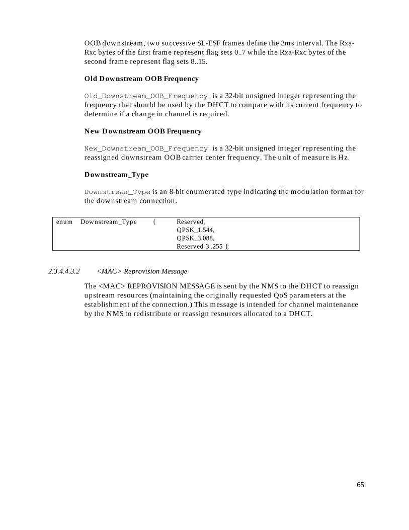
65
OOB downstream, two successive SL-ESF frames define the 3ms interval. The Rxa-Rxc bytes of the first frame represent flag sets 0..7 while the Rxa-Rxc bytes of thesecond frame represent flag sets 8..15.
Old Downstream OOB Frequency
Old_Downstream_OOB_Frequency is a 32-bit unsigned integer representing thefrequency that should be used by the DHCT to compare with its current frequency todetermine if a change in channel is required.
New Downstream OOB Frequency
New_Downstream_OOB_Frequency is a 32-bit unsigned integer representing thereassigned downstream OOB carrier center frequency. The unit of measure is Hz.
Downstream_Type
Downstream_Type is an 8-bit enumerated type indicating the modulation format forthe downstream connection.
enum Downstream_Type { Reserved,QPSK_1.544,QPSK_3.088,Reserved 3..255 };
2.3.4.4.3.2 <MAC> Reprovision Message
The <MAC> REPROVISION MESSAGE is sent by the NMS to the DHCT to reassignupstream resources (maintaining the originally requested QoS parameters at theestablishment of the connection.) This message is intended for channel maintenanceby the NMS to redistribute or reassign resources allocated to a DHCT.

66
Reprovision_Message (){ Bits Bytes Bit Number/ Description
Reprovision_Control_Field 1Reserved 2 7..6New_Downstream_IB_Frequency 1 5:{no,yes}New_Downstream_OOB_Frequency 1 4:{no,yes}New_Upstream_Frequency_Included 1 3:{no,yes}New_Frame_Length_Included 1 2:{no,yes}New_Cyclic_Assignment_Included 1 1:{no,yes}New_Slot_List_Included 1 0:{no,yes}
if (Reprovision_Control_Field ==New_Downstream_IB_Frequency) {
New_Downstream_IB_Frequency 32 4}if (Reprovision_Control_Field ==New_Downstream_OOB_Frequency) {
New_Downstream_OOB_Frequency 32 4Downstream_Type 8 1 {enum}
}if (Reprovision_Control_Field == New_Frequency_Included) {
New_Upstream_Frequency 32 4New_Upstream_Parameters 2
New_Upstream_Channel_Number 3 7..5Reserved 2 4..3Upstream_Rate 3 2..0:{enum}MAC_Flag_Set 5 7..3Reserved 3 2..0
}if (Reprovision_Control_Field == New_Frame_Length_Included){
New_Frame_Length 16 2}if (Reprovision_Control_Field == New_Slot_List_Included ||New_Cyclic_Assignment_Included) {
Number_of_Connections 8 1}for(i=0;i<Number_of_Connections;i++) {
Connection_ID 32 4if (Reprovision_Control_Field == New_Slot_List_Included)
{Number_Slots_Defined 8 1for(i=0;i<Number_Slots_Assigned;
i++){Slot_Number 13 2
}}if (Reprovision_Control_Field == New_Cyclic_Assignment_Included) {
Contentionless_Start 16 2Contentionless_Dist 16 2Number_Cyclic_Slots_Defined 16 2
}}
}
Reprovision Control Field

67
Reprovision_Control_Field specifies what modifications to upstreamresources are included.
It consists of the following subfields:
New_Upstream_OOB_Frequency is a Boolean that indicates that a newdownstream OOB frequency is specified in the message.
New_Upstream_IB_Frequency is a Boolean that indicates that a newdownstream IB frequency is specified in the message. This field is reserved inorder to maintain compatibility with DAVIC.
New_Upstream_Frequency_Include is a Boolean that indicates that a newupstream frequency is specified in the message.
New_Frame_Length_Include is a Boolean that indicates that a new upstreamframe is specified in the message.
New_Slot_List_Include is a Boolean that indicates that a new slot list isspecified in the message.
New_Cyclical_Assignment_Include is a Boolean that indicates that a newcyclical assignment is specified in the message.
New Downstream IB Frequency
New_Downstream_IB_Frequency is a 32-bit unsigned integer representing thereassigned downstream IB carrier center frequency. The unit of measure is Hz. Thisfield is not expected to be used but is reserved for compatibility with DAVIC.
New Downstream OOB Frequency
New_Downstream_OOB_Frequency is a 32-bit unsigned integer representing thereassigned downstream OOB carrier center frequency. The unit of measure is Hz.
Downstream_Type
Downstream_Type is an 8-bit enumerated type indicating the modulation format forthe downstream connection.
enum Downstream_Type { Reserved,QPSK_1.544,QPSK_3.088,Reserved 3..255 };
New Upstream Frequency
New_Upstream_Frequency is a 32-bit unsigned integer representing thereassigned upstream carrier center frequency. The unit of measure is Hz.

68
New Upstream Channel Number
New_Upstream_Channel_Number is a 3-bit unsigned integer that provides anidentifier for the upstream channel.
Upstream Rate
Upstream_Rate is an 3-bit enumerated type indicating the data rate for theupstream connection.
enum Upstream_Rate { Upstream_256K,Upstream_1.544M,Upstream_3.088M,Reserved 3..7 };
MAC_Flag_Set
MAC_Flag_Set is an 5 bit field representing the MAC Flag set assigned to theconnection.
New Frame Length
New_Frame_Length is a 16-bit unsigned integer representing the size of thereassigned upstream Contentionless based frame. The unit of measure is in slots.
Number of Slots Defined
Number_Slots_Defined is an 8-bit unsigned integer that represents the numberof slot assignments contained in the message. The unit of measure is slots.
Slot Number
Slot_Number is a 13-bit unsigned integer that represents the Contentionless basedSlot Number assigned to the Network Interface Module.
Contentionless Start
Contentionless_Start is a 16 bit unsigned integer that represents the startingupstream slot within the contentionless access region that is assigned to DHCT. TheDHCT may use the next Frame_Length slots of the contentionless access regions.
Contentionless Distance
Contentionless_Distance is 16 bit unsigned integer that represents the distancein upstream slots between additional slots assigned to the DHCT. The DHCT isassigned all slots that are a multiple of Contentionless_Distance from theContentionless_Start_Slot within the contentionless access region. The DHCT mayuse the next Frame_Length slots of the contentionless access regions from each ofthese additional slots.
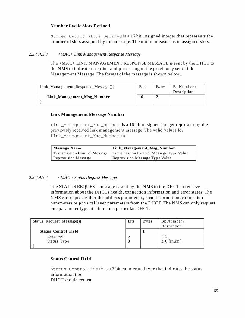
69
Number Cyclic Slots Defined
Number_Cyclic_Slots_Defined is a 16 bit unsigned integer that represents thenumber of slots assigned by the message. The unit of measure is in assigned slots.
2.3.4.4.3.3 <MAC> Link Management Response Message
The <MAC> LINK MANAGEMENT RESPONSE MESSAGE is sent by the DHCT tothe NMS to indicate reception and processing of the previously sent LinkManagement Message. The format of the message is shown below..
Link_Management_Response_Message(){ Bits Bytes Bit Number /Description
Link_Management_Msg_Number 16 2}
Link Management Message Number
Link_Management_Msg_Number is a 16-bit unsigned integer representing thepreviously received link management message. The valid values forLink_Management_Msg_Number are:
Message Name Link_Management_Msg_NumberTransmission Control Message Transmission Control Message Type ValueReprovision Message Reprovision Message Type Value
2.3.4.4.3.4 <MAC> Status Request Message
The STATUS REQUEST message is sent by the NMS to the DHCT to retrieveinformation about the DHCTs health, connection information and error states. TheNMS can request either the address parameters, error information, connectionparameters or physical layer parameters from the DHCT. The NMS can only requestone parameter type at a time to a particular DHCT.
Status_Request_Message(){ Bits Bytes Bit Number /Description
Status_Control_Field 1Reserved 5 7..3Status_Type 3 2..0:{enum}
}
Status Control Field
Status_Control_Field is a 3 bit enumerated type that indicates the statusinformation theDHCT should return

70
enum Status_Control_Field { Address_Params,Error_Params,Connection_Params,Physical_Layer_Params,Reserved 4..7 };
2.3.4.4.3.5 <MAC> Status Response Message
The <MAC> STATUS RESPONSE MESSAGE is sent by the DHCT in response to the<MAC> STATUS REQUEST MESSAGE issued by the NMS. The contents of theinformation provided in this message will vary depending on the request made bythe NMS and the state of the DHCT.

71
Status_Response_Message(){ Bits Bytes Bit Number/Description
DHCT_Status 4Reserved 29 31..3Network_Address_Registered 1 2:{no, yes}Default_Connection_Established 1 1:{no, yes}Calibration_Operation_Complete 1 0:{no, yes}
Response_Fields_Included 1Reserved 4 7..4Address_Params_Included 1 3:{no, yes}Error_Information_Included 1 2:{no, yes}Connection_Params_Included 1 1:{no, yes}Physical_Layer_Params_Included 1 0:{no, yes}
if (Response_Fields_Included ==Address_Params_Included) {
NSAP_Address 160 20MAC_Address 48 6
}if (Response_Fields_Included ==Error_Information_Included) {
Number_Error_Codes_Included 8 1for(i=0;i<Number_Error_Codes_Included;i++){
Error_Param_Code 8 1Error_Param_Value 16 2
}}if (Response_Fields_Included ==Connection_Params_Included) {
Number_of_Connections 8 1for(i=0;i<Number_of_Connections;i++){
Connection_ID 32 4}
}if (Response_Fields_Included ==Physical_Layer_Params_Included) {
Power_Control_Setting 8 1Time_Offset_Value 16 2Upstream_Frequency 32 4Downstream_Frequency 32 4
}}
DHCT Status
DHCT_Status is a 32-bit field that indicates the current state of the DHCT. Itcontains the following subfields:

72
Network_Address_Registered indicates that the Network Interface Modulehas registered its Network Address with the Application Module.
Default_Connection_Established indicates that the Network InterfaceModule has been assigned Default Connection parameters.
Calibration_Operation_Complete indicates that the Network InterfaceModule has been successfully calibrated.
Response Fields Included
Response_Fields_Included is an 8 bit unsigned integer that indicates whatparameters are contained in the upstream status response.
NSAP Address
NSAP_Address is a 20 byte address assigned to the DHCT.
MAC Address
MAC_Address is a 6 byte address assigned to the DHCT.
Number of Error Codes Included
Number_Error_Codes_Included is an 8-bit unsigned integer that indicates thenumber of error codes are contained in the response.
Error Param Code
Error_Param_Code is a 8-bit enumerated type representing the type of errorreported by the DHCT.
enum Error_Param_Code { Framing_Bit_Error_Count,Slot_Configuration_CRC_Error_Count,Reed_Solomon_Error_Count,ATM_Packet_Loss_CountReserved 4..255 };
Error Param Value
Error_Param_Value is an 16-bit unsigned integers representing error countsdetected by the DHCT.

73
Number of Connections
Number_of_Connections is an 8-bit unsigned integer that indicates the numberof connections that are specified in the response.
Connection ID
Connection_ID is a 32-bit unsigned integer representing the global connectionIdentifier used by the DHCT for this connection.
Power Control Setting
Power_Control_Setting is a 8-bit unsigned integer representing the actualpower used by the DHCT for upstream transmission. Unit of measure is 0.5 dBµV.
Time Offset Value
Time_Offset_Value is a 16-bit signed integer representing a relative offset of theupstream transmission timing. A negative value indicates an adjustment forward intime. A positive value indicates an adjustment back in time. The unit of measure is100 nsec.
Upstream Frequency
Upstream_Frequency is a 32-bit unsigned integer representing the channel onassigned to the connection. The unit of measure is in Hz.
Downstream Frequency
Downstream_Frequency is a 32-bit unsigned integer representing the Frequencywhere the connection resides. The unit of measure is in Hz.
2.3.4.4.4 MAC message timeouts
The minimum time that the NMS will wait for a response from the DHCT varies with themessage type as follows in Table 2-7:
Table 2-7 MAC Message TimeoutsMessage TimeoutRanging & Power Calibration ResponseMessage:
2 seconds
Connect Response Message: 10 secondsReservation ID Response Message NoneRelease Message 10 seconds (1 retry)Transmission Control Message 10 seconds (no retries)Status Response Message 2 × Idle period
The modulator expects to receive <MAC> Idle messages from each settop periodically,according to the Idle period provided in the NMS provisioning parameter screen. The QPSKmodulator will wait 2 idle periods before sending a <MAC> Status Request message. The

74
control field of the <MAC> Status Request Message will indicate a request for connectionparameters. If the settop doesn’t send a response after 3 <MAC> Status Request Messages, allof its connections are released at the modulator. Additionally, if the settop sends backconnection parameters that contain connection IDs the modulator didn’t assign, a <MAC>Release message is sent to release the connection(s).