analysis of an advanced technology subsonic … technical memorandum 8%68 ' analysis of an...
TRANSCRIPT

NASA Technical Memorandum 8%68 '
Analysis of an Advanced Technology Subsonic Turbofan Incorporating
May 1983-
Revolutionary Materials
Gerald Knip, Jr . Lewis Research Center Cleveland, Ohio
(bASB-TH-8S868) A N A L Y S X S CE A # AEVAYCED Y87-226EO
'IECHNCLCGY ZCESCYIC TOGLEOEAb I L C C R P Q R A T I P G SEVCLUPICIAGY H&!iEBI;ALS ( t iAS.4) 2 5 y A v a i l : NPIS B C BCZ/&H A01 CSCL 21E Unclas
# / 0 7 0074220
https://ntrs.nasa.gov/search.jsp?R=19870013247 2018-05-13T22:02:55+00:00Z
ANALYSIS OF AN ADVANCED TECHNOLOGY SUBSONIC TURBOFAN I N C O R P O R A T I N G
REVOLUTIONARY MATERIALS
Gerald Knip, J r . N a t i o n a l Aeronaut ics and Space A d m i n i s t r a t i o n
Lewis Research Center Cleveland, Ohio 44135
I SUMMARY
Successfu l implementat ion o f r e v o l u t i o n a r y composite m a t e r i a l s i n an advanced t u r b o f a n o f f e r s t h e p o s s i b i l i t y o f f u r t h e r improvements i n engine performance and t h r u s t - t o - w e i g h t r a t i o r e l a t i v e t o c u r r e n t m e t a l l i c m a t e r i a l s . The present a n a l y s i s determines the approximate engine c y c l e and c o n f i g u r a t i o n
l i n e engine i n terms of i t s p o t e n t i a l f u e l savings f o r an i n t e r c o n t i n e n t a l
(\1
In f o r an e a r l y 21s t cen tu ry subsonic tu rbo fan i n c o r p o r a t i n g a l l composite mate-
I W
d-
m I r i a l s . The advanced engine i s eva luated r e l a t i v e t o a c u r r e n t technology base-
I quad je t hav ing a des ign range o f 5500 nml and a payload o f 500 passengers.
The r e s u l t a n t near optimum, uncooled, two-spool , advanced engine has an o v e r a l l p ressure r a t i o o f 87, a bypass r a t i o o f 18, a geared fan, and a t u r b i n e
engine y i e l d s a 22 pe rcen t improvement i n c r u i s e TSFC and a 36-percent reduc t - i o n i n engine we igh t . Together these improvements r e s u l t i n a 33-percent f u e l sav ing f o r t h e s p e c i f i e d m iss ion .
I I , r o t o r - i n l e t temperature o f 3085 O R . R e l a t i v e t o t h e base l i ne , t h e advanced
Various advanced composite ma te r ia l s a r e used th roughout t h e engine. For example, advanced polymer composite m a t e r l a l s a r e used f o r t h e f a n and t h e low pressure compressor (LPC). A T i meta l m a t r i x composite i s used f o r t h e h i g h pressure compressor ( H P C ) t o accommodate t h e h ighe r o p e r a t i n g temperatures. Ceramic composites a r e used f o r t he combustor and b o t h t u r b i n e s .
The advanced eng lne 's performance inc ludes aggress ive component e f f i c i e n - c i e s based on these new m a t e r l a l s and s t r u c t u r a l changes such as swept f a n and compressor b lades , uncooled tu rb ines , reduced h u b - t i p r a t i o s , h ighe r b lade load lngs , reduced c learances, and th ree-d imens iona l des ign concepts.
I N T R O D U C T I O N
Over t h e p a s t 40 y r , advanced t u r b l n e engines have been t h e pac ing i t e m i n terms o f t h e U.S. c o m p e t l t l v e edge i n commercial a v i a t i o n . Dur ing t h i s p e r i o d t h e s p e c i f i c f u e l consumption (TSFC) o f subsonic t u r b i n e engines has been reduced by about 40 percent . This r e d u c t i o n has been achieved th rough improvements i n component aerodynamics, m a t e r i a l s , and t u r b i n e c o o l i n g e f f e c - t i veness . Improvements i n m a t e r i a l s and t u r b i n e c o o l i n g have r e s u l t e d i n t h e maximum t u r b i n e temperature be ing increased f rom 1000 t o 2600 O F .
o v e r a l l p ressure r a t i o s have increased f rom 5 t o over 38 ( r e f s . 1 t o 3) , and bypass r a t i o s f rom 0 ( t u r b o j e t ) t o 7 ( t u r b o f a n ) . Advanced m e t a l l i c m a t e r i a l s have a l s o a l lowed t i p speeds and b lade l o a d i n g t o be inc reased r e s u l t i n g i n fewer b u t more e f f i c i e n t stages and l l g h t e r we lgh t components. Composite m a t e r i a l s a re j u s t beg inn ing t o be used I n t u r b i n e engines and then o n l y f o r n o n r o t a t i n g components.
Engine
Succesqful imp lementa t ion of r e v o l u t i o n a r y composite m a t e r i a l s (e.g., polymer, metal m a t r i x , and h igh- tempera ture n o n m e t a l l l c composi tes) i n an advanced tu rbo fan o f f e r s t h e p o s s l b l l l t y o f s t i l l f u r t h e r improvements i n engine performance and t h r u s t - t o - w e i g h t r a t l o s r e l a t i v e t o c u r r e n t conven- t i o n a l m a t e r i a l s ( i . e . , t i t a n i u m , s t e e l , and s u p e r a l l o y s ) . Advanced composite m a t e r l a l s w i t h advanced s t r u c t u r e s w i l l a l l o w h i g h e r t i p speeds and t h l n n e r blades r e s u l t i n g i n fewer and more e f f l c i e n t s tages. Advanced n o n m e t a l l i c composites w i l l a l l o w t u r b i n e s t o opera te uncooled a t h ighe r t u r b i n e i n l e t temperatures r e s u l t i n g i n h ighe r o v e r a l l p ressure r a t i o s and bypass r a t i o s , thereby improv ing performance. Lower m a t e r i a l d e n s i t i e s and, t h e r e f o r e , reduced blade weights w l l l r e s u l t i n lower s t resses and reduced engine we igh t . Advanced s t r u c t u r e s such as drum c o n s t r u c t i o n r a t h e r than d i s k s w i l l a l s o r e s u l t i n l o w e r engine we lgh ts .
The purpose o f t h i s s tudy was t o (1) determine t h e approx imate c y c l e and c o n f i g u r a t i o n f o r a t u r b o f a n engine i n c o r p o r a t i n g r e v o l u t i o n a r y a l l - c o m p o s i t e m a t e r l a l s , and ( 2 ) eva lua te t h e p o t e n t i a l f u e l sav ing r e l a t i v e t o an engine us ing c u r r e n t technology ( c u r r e n t m a t e r i a l ) f o r a commercial subsonic t r a n s - p o r t miss ion. This was done by conduct ing bo th engine c y c l e and f l o w p a t h s tud ies .
ANALYSIS
Mlss ion
For t h i s s tudy, an i n t e r c o n t i n e n t a l quad je t hav ing a des ign range o f 5500 nmi and a payload o f 500 passengers was assumed. Engines hav ing a t h r u s t o f about 10 000 l b a t Mach 0.8 and 35 000 f t would be r e q u i r e d . Th is s i z e engine was, t h e r e f o r e , cons idered i n t h e p resen t s tudy . S e n s i t i v i t y f a c t o r s f o r engine performance (TSFC) and we lgh t were used t o de termine changes i n f u e l consumption.
Base l i ne Engine
The base l lne engine used f o r t h e s tudy i s s i m i l a r t o t h e Maximum E f f i - c iency Energy E f f i c i e n t Engine o f re fe rence 4. I t i s a two-spool engine w i t h the f a n and t h e low pressure compressor d i r e c t l y d r i v e n by t h e low pressure t u r b i n e . The engine I s based on c u r r e n t technology. Compressor p ressure r a t i o s a r e l i s t e d i n t a b l e I a long w i t h t h e t u r b i n e r o t o r - i n l e t temperature. A i r f o r coo l i ng t h e t u r b i n e i s e x t r a c t e d a t t h e e x i t o f t h e h i g h pressure com- pressor . Turbine c o o l i n g requi rements f o r t h e b a s e l i n e engine a r e based on t h e method o u t l i n e d i n re fe rence 5. Compressor e x i t b leed requi rements f o r t u r b i n e coo l i ng a re based on va lues f o r c o o l i n g e f f e c t i v e n e s s assuming advanced convec t ion coo l i ng w i t h t r a i l i n g edge e j e c t i o n . temperatures were used f o r t h e vanes (2200 O R ) and b lades (2100 O R ) . Based on the t u r b i n e stage c o o l i n g requl rements, t h e s tage e f f i c i e n c y was c o r r e c t e d acco rd ing l y .
Cur ren t a l l o w a b l e b u l k meta l
2
Advanced 1.nglnes
Cyc le s tudy - f o r t h e advanced engine, a c y c l e s tudy was conducted t o d e f i n e an engine c y c l e based on t h r u s t s p e c i f l c f u e l consumptlon (TSFC) as t h e f i g u r e o f m e r i t . TSFC i s i n f l uenced by engine c y c l e parameters such as over - a l l p ressu re r a t o ( O P R ) , bypass r a t i o (BPR), t u r b i n e r o t o r - i n l e t temperature (T41) , component e f f i c i e n c i e s , and component c o n f i g u r a t i o n s . des ign -po in t s tudy program ( F A C E ) was used t o determine des ign p o i n t TSFC's and t o screen va r ious separate f l o w tu rbo fan c o n f i g u r a t i o n s . I n p u t s f o r t h i s program i n c l u d e f a n and compressor pressure r a t i o s , number o f stages, t y p e o f compressor ( a x i a l o r c e n t r i f u g a l ) , t u r b l n e r o t o r - i n l e t temperature, number o f spools, number o f t u r b i n e stages, and type o f t u r b i n e c o o l i n g c o n f i g u r a t i o n .
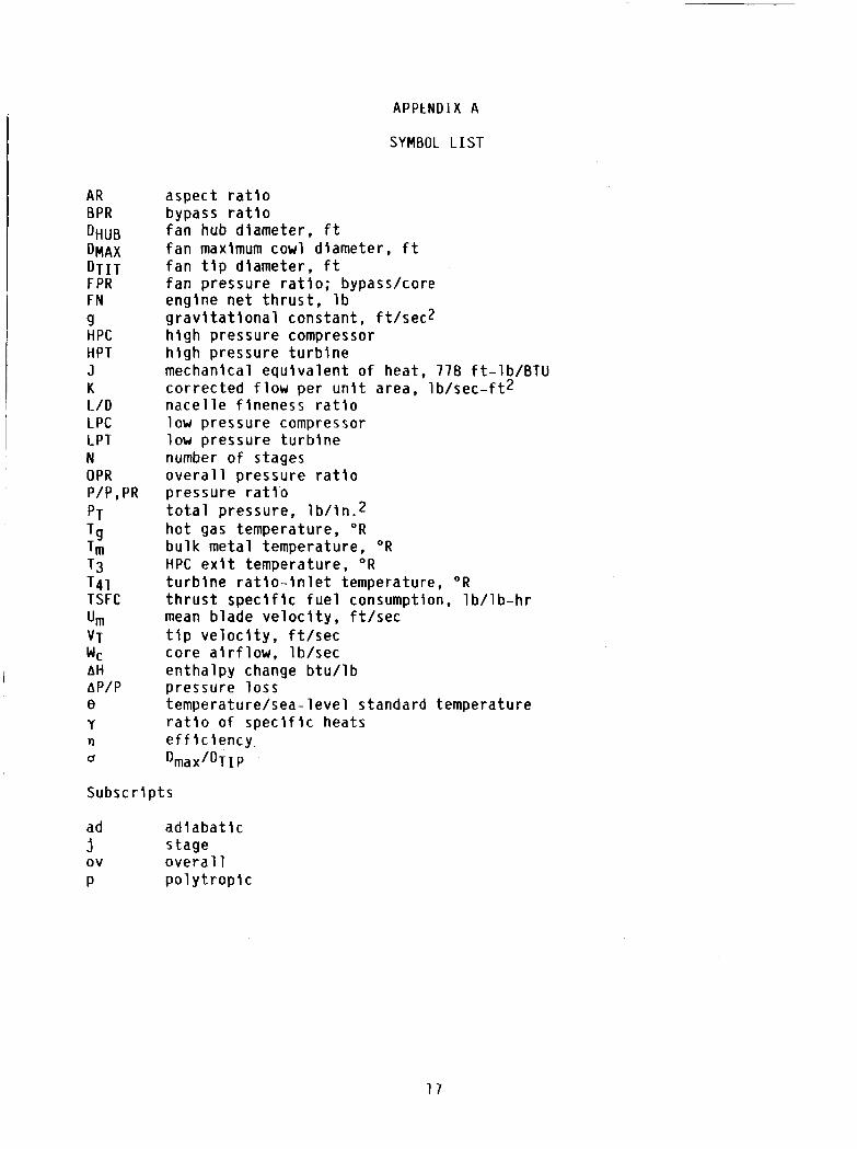
An in-house
For t h e present s tudy, two l e v e l s o f compressor and t u r b i n e e f f i c i e n c i e s were cons idered. One l e v e l represents c u r r e n t techno logy as opposed t o t h e aggress ive second l e v e l , which represents advanced technology. Based on d i s - cuss ions w i t h NASA component personnel and a s tudy conducted under NASA con- t r a c t ( r e f . 4 ) , h igher component e f f i c i e n c i e s due t o t h e use o f advanced composite m a t e r i a l s were p o s t u l a t e d based on components hav ing t h i n n e r b lades, h i g h e r t i p v e l o c i t i e s , uncooled tu rb ines , improved c lea rance c o n t r o l , and reduced h u b - t i p r a t i o s i n a d d i t i o n t o maklng more e f f i c i e n t use o f advanced th ree-d imens iona l , CFM des ign technology. E f f i c i e n c i e s f o r t h e compressors and t u r b i n e s a r e determined on t h e bas i s o f s tage pressure r a t l o and work f a c t o r ( g J AH/N/U&), r e s p e c t i v e l y . Symbols are d e f i n e d i n appendix A. Compressor and t u r b i n e e f f i c i e n c i e s a r e then cor rec ted f o r s i z e e f f e c t s . Turb ine e f f i - c i e n c i e s a r e a l s o c o r r e c t e d t o account f o r c learance and t u r b i n e c o o l i n g e f f e c t s .
Advanced Components and M a t e r l a l s
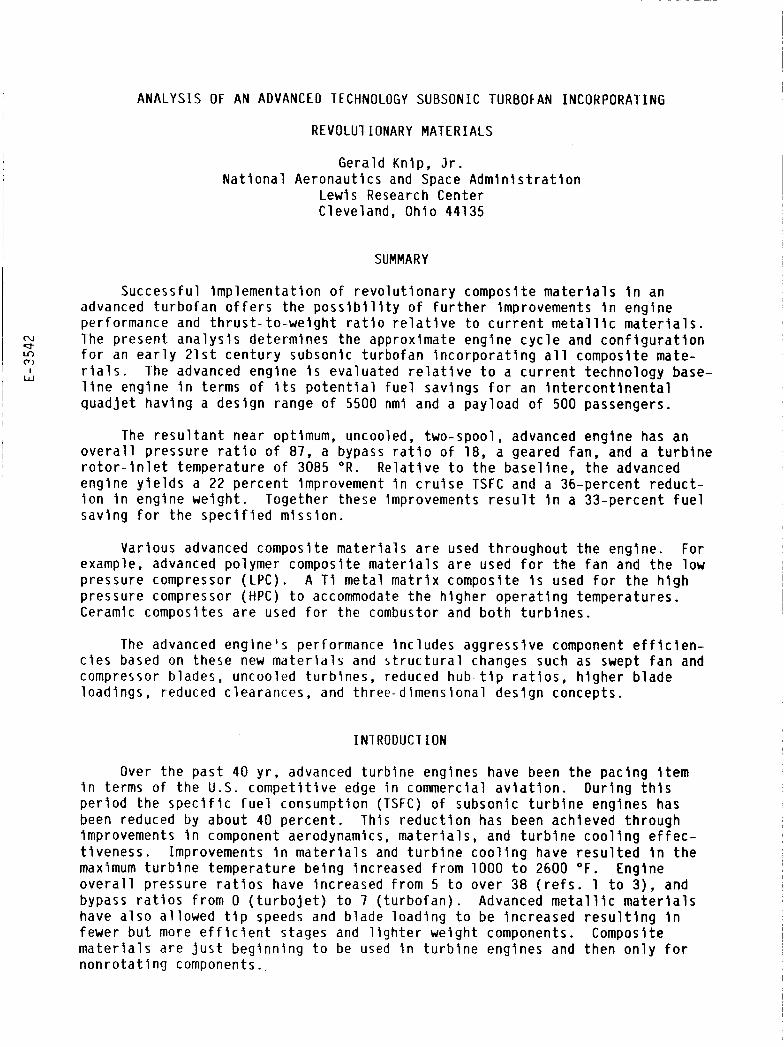
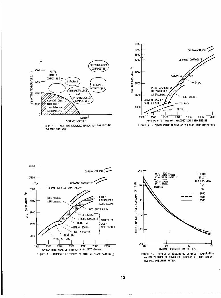
Advanced m a t e r i a l s c u r r e n t l y be ing cons idered t o a l l o w f u t u r e t u r b i n e engines t o opera te e f f i c i e n t l y a t h i g h temperatures and pressures a r e shown i n f i g u r e 1.
Compressors. - Both polymer and metal m a t r i x composites ( r e f s . 6 t o 9 ) a r e cand ida tes f o r f a n b lades and t h e f r o n t stages o f a compressor. For t h e l a t t e r stages o p e r a t i n g a t h i g h e r temperatures meta l m a t r i x and i n t e r m e t a l l i c s a r e p o s s i b i l i t i e s . The r o t o r may cons is t o f a drum f o r r e t a i n i n g t h e b lades ( o u t s i d e t h e scope o f t h e p resen t s tudy) .
Combustor. - Advanced m a t e r i a l s are a l s o be ing cons idered f o r f u t u r e t u r - b i n e englne combustors. These m a t e r i a l s i n c l u d e d o x i d e d i s p e r s i o n s t rengthened (ODS) supera l l oys and nonmeta l l l c composites, such as ceramic composites and carbon-carbon. These m a t e r l a l s would enable t h e combustor t o be operated a t h i g h e r temperatures w l t h l i t t l e o r no coo l ing .
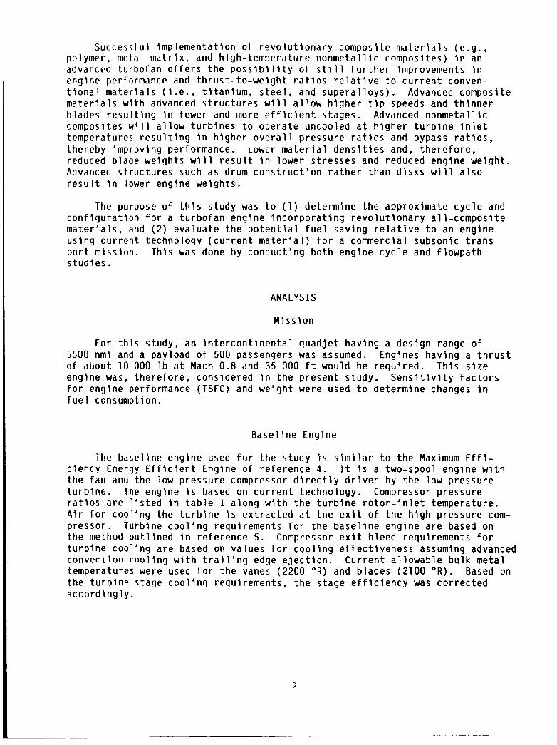
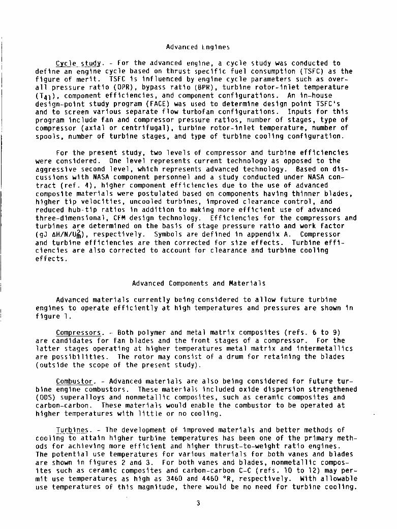
Turb lnes . - The development o f improved m a t e r i a l s and b e t t e r methods o f c o o l i n g t o a t t a i n h i g h e r t u r b i n e temperatures has been one o f t h e p r imary meth- ods f o r a c h l e v i n g more e f f i c i e n t and h lgher t h r u s t - t o - w e i g h t r a t i o engines. The p o t e n t i a l use temperatures f o r var ious m a t e r i a l s f o r b o t h vanes and b lades a r e shown i n f i g u r e s 2 and 3. For bo th vanes and b lades, n o n m e t a l l i c compos- i t e s such as ceramic composites and carbon-carbon C-C ( r e f s . 10 t o 12) may per - m i t use temperatures as h l g h as 3460 and 4460 O R , r e s p e c t i v e l y . Wi th a l l o w a b l e use temperatures o f t h i s magnitude, there would be no need f o r t u r b i n e c o o l i n g .
3

~ _ _ _ Nozzles. - Advanced m a t e r i a l s such as n o n m e t a l l i c composites a r e a l s o be ing considered f o r t u r b i n e engine nozz les .
Flowpath. - Based on t h e c y c l e s t u d i e s , f lowpaths f o r se lec ted engines were then determined us ing NNEP ( r e f . 13) and t h e NASA we igh t code ( r e f . 14) . Thermodynamic i n p u t s requ i red f o r t h e we igh t code a r e determined i n NNEP. we igh t program determlnes t h e we igh t o f each component i n t h e engine such as compressors, burner , t u r b i n e s , frames, gearbox, and accessor ies . Component we igh ts a r e determined on t h e bas i s of a p r e l i m i n a r y des ign approach cons ider - i n g s t r e s s l e v e l s , maximum temperature, m a t e r i a l d e n s i t y , geometry, s tage load- i n g , and h u b - t i p r a t i o . f o r each component and t h e da ta presented I n re fe rence 4 , t h e we igh t program i n p u t parameters f o r t he b a s e l i n e engine were updated t o account f o r d i f f e r - ences between t h e base l i ne t u r b o f a n and t h e advanced t u r b o f a n u s l n g advanced composite ma te r ia l s . The m a t e r i a l f o r each component was se lec ted on t h e b a s i s o f maximum component temperature. gearbox housing, a meta l m a t r i x composite may r e s u l t i n a s t i f f e r housing. However, f o r t h i s s tudy no we igh t advantage was considered.
The
Based on t h e advanced m a t e r i a l s o f f i g u r e 1 s e l e c t e d
R e l a t i v e t o a c u r r e n t aluminum o r magneslurn
I n s t a l l e d performance. - The u n i n s t a l l e d performances f o r t h e b a s e l i n e and t h e advanced engines w e r e c o r r e c t e d f o r n a c e l l e drag. Based on t h e d i f f e r e n c e s i n i n s t a l l e d TSFC and we lgh t between the two engines, f u e l savings were d e t e r - mined us ing mlss ion s e n s i t i v i t y f a c t o r s ( r e f . 15). These s e n s i t i v i t y f a c t o r s were determined f rom a m iss ion a n a l y s i s o f an i n t e r c o n t i n e n t a l , t u r b o f a n pow- ered t r a n s p o r t hav ing a range o f 5500 nmi and a pay load o f 500 passengers.
RESULTS AND DISCUSSION
To min imize TSFC f o r an advanced t u r b o f a n engine p r o v i d i n g a t h r u s t o f 10 000 l b a t Mach 0.8 and 35 000 f t , t h e f o l l o w l n g parameters were considered: t u r b i n e r o t o r - i n l e t temperature (T41) , f a n and compressor p ressure r a t i o s , o v e r a l l pressure r a t i o ( O P R ) , bypass r a t i o ( B P R ) , and number o f stages f o r a t w o - spool engl ne.
E f f e c t o f Advanced Engine Design Parameters on Performance
Turb lne r o t o r - i n l e t temperature (T41) . - The l e v e l o f t u r b i n e I n l e t temperature can a f f e c t n o t o n l y engine performance ( T S F C ) , b u t a l s o engine s i z e and, t h e r e f o r e we igh t . The e f f e c t o f T41 on TSFC f o r a range o f O P R ' s I s shown i n f i g u r e 4 . For these advanced engines, t h e t u r b i n e s a re uncooled. The pressure r a t i o f o r t h e f a n (1.55(bypass)/1.4(core)) and t h e low pressure compressor ( L P C ) were h e l d cons tan t w h i l e t h e pressure r a t i o o f t h e h i g h pres- sure compressor (HPC) was v a r l e d t o ach ieve t h e s p e c l f l e d OPR. The number o f a x i a l stages f o r t h e LPC and t h e HPC w e r e f i x e d a t 3 and 11, r e s p e c t i v e l y . A l though fewer stages f o r t h e HPC cou ld be used f o r t h e lower p ressure r a t i o s , t h i s would r e s u l t I n lower compressor e f f i c i e n c i e s and, t h e r e f o r e , a h i g h e r 1 S F C . Two a x i a l s tage t u r b i n e s were used f o r t h e h i g h pressure t u r b i n e ( H P T ) and f i v e f o r t h e low pressure t u r b i n e (LPT). Bypass r a t i o was op t im ized f o r each c y c l e w l t h respec t t o TSFC. 2760 and 3085 O R have a smal l e f f e c t on TSFC ( f i g . 4 ) due I n p a r t t o t h e aggress l ve component e f f l c l e n c i e s f o r t h e advanced engine. However, i nc reas - I n g t h e OPR f rom 40 ( c u r r e n t techno logy) t o 100 r e s u l t s I n about an 8 . 5 percen t decrease I n TSFC. The e f f e c t o f t u r b i n e temperature on s p e c i f l c t h r u s t (based
Turb ine i n l e t temperatures (T41) between
4

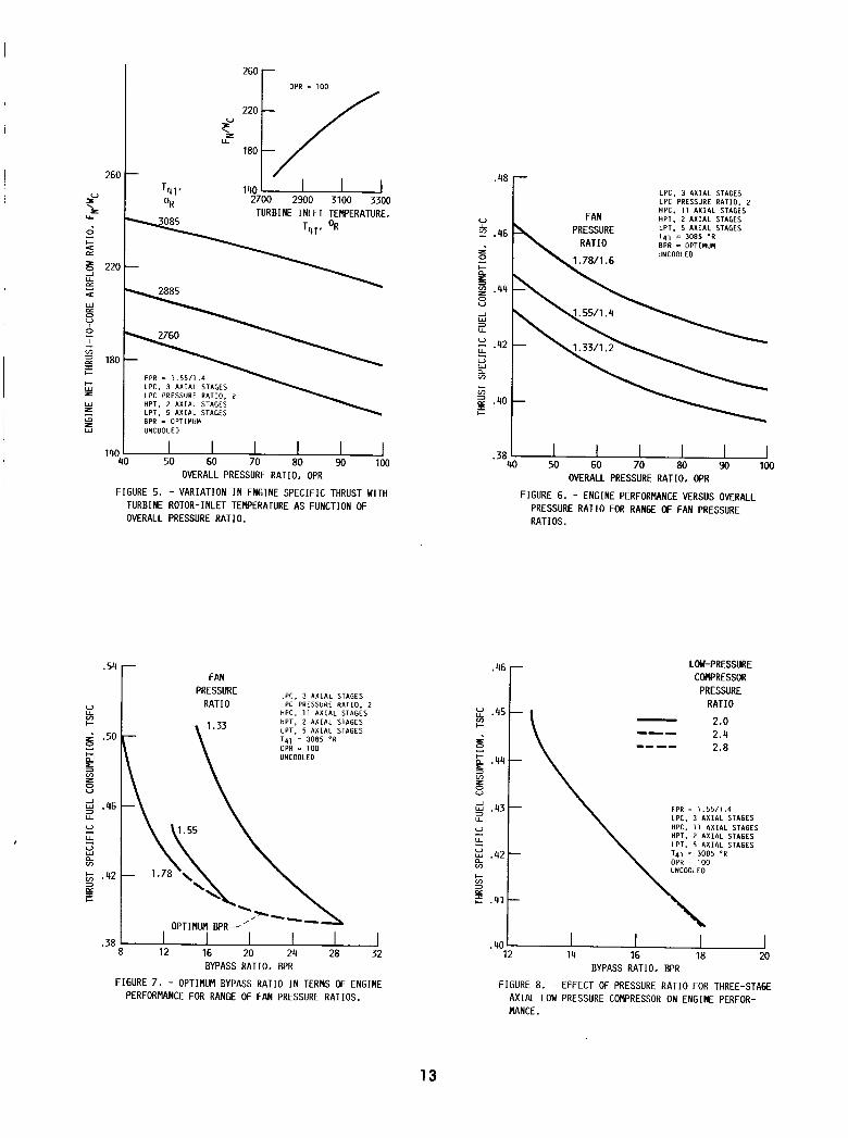
I on co re f l o w ) i s shown i n f i g u r e 5. I nc reas ing T41 f rom 2760 t o 3085 O R
I r e s u l t s i n a 35 pe rcen t Inc rease i n s p e c i f i c t h r u s t . A h ighe r T41 r e s u l t s i n a somewhat h ighe r s p e c i f i c t h r u s t but a l s o a h ighe r TSFC. S ince f u e l con- sumption i s more s e n s i t i v e t o T S F C than engine s i ze , and t h e r e f o r e we igh t , a temperature o f 3085 O R was se lec ted .
~
Fan p ressu re r a t i o . - The e f f e c t o f f a n pressure r a t i o (and t h e r e f o r e BPR) on TSFC i s shown i n f i g u r e 6. Again, t h e LPC p ressu re r a t i o was f i x e d a t 2 and t h e HPC pressure r a t i o va r ied . Decreasing t h e f a n pressure r a t i o f r o m 1.78 t o 1.33 r e s u l t s i n about a 7 percent decrease i n TSFC. Lower f a n p ressu re r a t i o s w i t h t h e i r assoc ia ted lower t i p speeds can be accommodated by means o f a gearbox w i t h o u t p e n a l i z i n g t u r b i n e e f f i c i e n c y o r t u r b i n e we igh t . For an OPR o f 100, f i g u r e 7 shows t h e e f f e c t o f BPR on TSFC. The optimum BPR increases f rom 18 t o 28 as f a n pressure r a t i o i s decreased f rom 1.55 t o 1.33. Corre- spond ing ly , TSFC decreases by 2.5 percent. However, s ince t h e h i g h e r BPR would r e s u l t i n a s i g n i f i c a n t i nc rease i n engine s i z e and, t h e r e f o r e drag, a f a n pressure r a t i o of 1.55 was se lec ted f o r t h e advanced engine.
Low pressure compressor. - Whereas t h e f a n i s connected t o t h e l ow pres- sure t u r b i n e by means of a gearbox, t he LPC i s d i r e c t l y connected t o t h e t u r - b ine . Opera t ing t h e LPC a t t h e same speed as t h e t u r b i n e inc reases t h e t i p speed, r e s u l t i n g i n fewer stages f o r the same pressure r a t i o . I n c r e a s i n g t h e pressure r a t i o o f t h e th ree-s tage LPC from 2 t o 2.8 ( f i g . 8) has a lmost no e f f e c t on TSFC. A l though t h e pressure r a t i o o f t h e LPC does n o t a f f e c t pe r - formance, i t may have t o be m o d i f i e d t o change t h e r e q u i r e d p ressu re r a t i o o f t h e HPC when one cons iders component dlameters f o r t h e f l owpa th . To reduce t h e p ressu re r a t i o o f t h e HPC, an I n i t l a l p ressure r a t i o o f 2.8 f o r t h e LPC was s e l e c t e d f o r t h e advanced engine. Based on t h e r e l a t i v e l y smal l p e n a l t y assoc ia ted w i t h reduc ing t h e OPR f rom 100 t o 87 ( f i g . 6), an OPR o f 87 was se lec ted f o r t h e advanced engine.
High Pressure Compressor (HPCL. - Cur ren t technology a l l - a x i a l HPC 's have an average s tage pressure r a t i o o f about 1.3. Using t h i s as t h e average s tage pressure r a t i o , t h e HPC f o r an OPR o f 60 and 87 would r e q u i r e -11 and 13 stages, r e s p e c t i v e l y . For an OPR o f 87, t h e e f f e c t on TSFC o f reduc ing t h e number o f HPC stages f rom 13 t o 10 i s minor ( f i g . 9 ) . However, 10 o r 11 s tages may be advantageous i n terms o f engine l eng th , welght , and cos t . As a r e s u l t t h e average s tage pressure r a t i o would i nc rease t o 1.39 and 1.35, r e s p e c t i v e l y . These increased pressure r a t i o s can be achieved by means o f h i g h e r t i p speeds and/or inc reased b lade load ing .
A x i a l - c e n t r i f u g a l HPC. - I n a d d i t i o n t o t h e a l l - a x i a l h i g h pressure com- pressor p r e v i o u s l y d iscussed, an a x i a l - c e n t r l f u g a l HPC was a l s o cons idered ( f i g . 1 0 ) . F i g u r e 10 shows t h e optimum p ressu re r a t i o s p l i t i n terms o f TSFC f o r va r ious a x i a l - c e n t r i f u g a l compressors hav ing an o v e r a l l p ressure r a t i o o f 87. A t these h i g h pressure r a t i o s , i t may be necessary t o r e p l a c e some o f t h e l a t t e r a x i a l stages (because o f minimum b lade h e i g h t l i m i t a t i o n s o f -1/2 i n . ) w i t h a c e n t r i f u g a l s tage. TSFC decreases as t h e number o f a x i a l stages i s inc reased f rom 3 t o 5 due t o t h e h igher e f f i c i e n c y o f t h e a x i a l stages. The optimum pressure r a t i o f o r t h e c e n t r i f u g a l s tage decreases f rom about 6 t o 4 as t h e number o f a x i a l stages increases f rom 4 t o 5 . The average p ressu re r a t i o f o r t h e a x i a l s tage i s -1.47. Because o f t h e s l i g h t l y lower TSFC ( f i g . 9 ) f o r t h e a l l - a x i a l compressor, i t was se lec ted f o r t h e advanced engine.
High pressure t u r b i n e ( H P T ) . - The a c t u a l s tage mean v e l o c i t y o f t h e HPT depends on t h e RPM o f t h e HPC and/or the t u r b i n e work f a c t o r ( g J AH/N/U$).
5
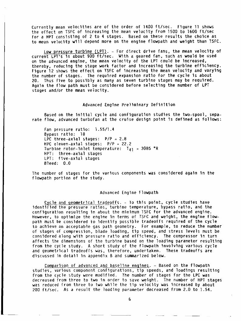
C u r r e n t l y mean v e l o c l t l e s a re o f t h e order o f 1400 f t / s e c . F l g u r e 11 shows the e f f e c t on TSFC of l n c r e a s l n g t h e mean v e l o c l t y f rom 1500 t o 1600 f t / s e c f o r a HPT c o n s i s t i n g o f 2 t o 4 stages. t o mean v e l o c l t y w i l l depend more on t h e engine f l owpa th and we lgh t t han TSFC.
Based on these r e s u l t s t h e cho lce as
Low pressure t u r b i n e (LPT). - For d l r e c t d r l v e fans , t h e mean v e l o c l t y o f c u r r e n t LPT's . Is about 900 f t / s e c . Wl th a geared fan , such as would be used on t h e advanced engine, t h e mean v e l o c l t y o f t h e LPT cou ld be lncreased, thereby, reduclng t h e s tage work f a c t o r and i n c r e a s i n g t h e t u r b l n e e f f l c l e n c y . F lgu re 12 shows t h e e f f e c t on TSFC o f l n c r e a s l n g t h e mean v e l o c l t y and v a r y l n g t h e number o f stages. 20. Agaln t h e f l o w p a t h must be consldered b e f o r e s e l e c t l n g t h e number o f LPT stages and/or t h e mean v e l o c l t y .
The r e q u i r e d expansion r a t i o f o r t h e c y c l e i s about Thus f i v e t o p o s s i b l y as many as seven t u r b i n e stages may be requ i red .
Advanced Engine P r e l l m l n a r y D e f l n l t l o n
Based on t h e l n i t l a l c y c l e and c o n f l g u r a t l o n s t u d i e s t h e two-spool, sepa- r a t e f l o w , advanced t u r b o f a n a t t h e c r u l s e des lgn p o l n t l s d e f l n e d as f o l l o w s :
Fan pressure r a t i o : 1.55/1.4 Bypass r a t i o : 18 LPC t h r e e - a x i a l s tages: P /P = 2.8 HPC e leven-ax la l s tages: P / P = 22.2 Turb ine r o t o r - i n l e t temperature: T41 = 3085 O R
HPT: t h r e e - a x l a l stages LPT: f l v e - a x i a l stages Bleed: 0.0
The number o f stages f o r t h e va r ious components was cons ldered aga ln I n t h e f l owpa th p o r t i o n o f t h e s tudy .
Advanced Englne Flowpath
Cycle and geomet r lca l t r a d e o f f s . - l o t h l s p o l n t , c y c l e s t u d i e s have l d e n t l f l e d t h e pressure r a t l o s , t u r b l n e temperature, bypass r a t l o , and t h e c o n f l g u r a t l o n r e s u l t l n g I n about t h e mlnlmum TSFC f o r t h e advanced englne. However, t o o p t l m l z e t h e engine I n terms of TSFC and we lgh t , t h e engine f l o w - p a t h must be cons ldered t o l d e n t l f y p o s s i b l e t r a d e o f f s r e q u i r e d o f t h e c y c l e t o achleve an acceptab le gas pa th geometry. For example, t o reduce t h e number o f stages o f cornpresslon, b lade load lng , t l p speed, and s t r e s s l e v e l s must be consldered a long wqth pressure r a t i o and e f f l c l e n c y . The compressor i n t u r n a f f e c t s the dimensions o f t h e t u r b l n e based on t h e l o a d l n g parameter r e s u l t l n g f rom t h e cyc le s tudy. A s h o r t s tudy o f t h e f l owpa th i n v o l v i n g var ious c y c l e and geomet r ica l t r a d e o f f s was, t h e r e f o r e , undertaken. These t r a d e o f f s a r e d lscussed i n d e t a l l I n appendlx B and summarlzed below.
Comparlson o f advanced and b a s e l l n e engines. - Based on t h e f l owpa th s tud les , var lous component c o n f l g u r a t l o n s , t i p speeds, and load ings r e s u l t l n g from t h e cyc le s tudy were m o d i f l e d . The number o f stages f o r t h e LPC was decreased f rom t h r e e t o two I n o rder t o save we igh t . was reduced f r o m t h r e e t o two w h i l e the t l p v e l o c l t y was lnc reased by about 200 f t / s e c . A s a r e s u l t t h e l o a d i n g parameter decreased f rom 2.0 t o 1.54.
The number o f HPT stages
6
I n a d d i t i o n t h e l o a d i n g parameter f o r the LPT was Increased f rom 1.52 t o 1.86. These changes reduced t h e l e n g t h of t h e t r a n s i t i o n d u c t between t h e HPT and the LPT i n a d d i t i o n t o reduc ing engine weight. The r e s u l t i n g f l owpa th f o r the advanced t u r b o f a n engine 4s shown i n f i g u r e 13. For purposes o f comparison, t h e f l o w p a t h f o r t h e b a s e l i n e engine I s shown i n f i g u r e 14. i s sma l le r f o r t h e b a s e l i n e because of i t s lower bypass r a t i o . Core r a d i i f o r t h e advanced engine are, i n general , smal ler due t o t h e h ighe r t i p v e l o c l t i e s . Engines hav ing h ighe r bypass r a t i o s and a d i r e c t d r i v e f a n u s u a l l y have a longer t r a n s i t i o n s e c t i o n between t h e tu rb ines so as t o achieve h ighe r e f f i - c i e n c i e s f o r t h e r e q u i r e d work loads. This can be seen by comparing f i g u r e s 13 and 14.
The f a n diameter
Parameters r e s u l t i n g f rom the c y c l e and t h e f l o w p a t h s t u d i e s f o r t h e advanced engine a r e compared i n t a b l e s I 1 and 111 w i t h those f o r t h e b a s e l i n e engine. Table I 1 compares var ious geometric parameters, t h e number o f stages, and the number o f r o t o r blades. Table I 1 1 compares t h e cyc les , and f l owpa th temperatures and pressures . Engine OPR and t u r b i n e r o t o r - i n l e t temperature (T41) inc reased f rom 42.5 and 2775 O R f o r t h e b a s e l i n e engine t o 87 and 3085 O R f o r t h e advanced tu rbo fan . h ighe r m a t e r i a l s . The h ighe r OPR i s achieved .in one l e s s s tage o f compression. Because o f t h e h ighe r o p e r a t i n g pressure r a t i o s , temperatures e x l t i n g t h e va r ious components a r e i n general h ighe r .
Although t h e advanced engine operates a t a 141, i t i s uncooled due t o t h e higher use temperature o f t h e advanced
Based on temperatures assoc ia ted w i t h t h e LPT of t h e advanced engine, a c u r r e n t m a t e r i a l ( d e n s i t y o f 0.3 l b / i n . ) cou ld be considered f o r t h i s compo- nen t . However, an advanced m a t e r i a l such as a ceramic composite ( d e n s i t y o f 0.115 l b / i n . 3 ) would reduce t h e we igh t of t h e engine by 7 .5 pe rcen t , f i g u r e 15. Advanced m a t e r i a l s considered f o r t h e o t h e r components o f t h e advanced engine a r e l i s t e d I n t a b l e I V .
F i g u r e 16 compares t h e u n i n s t a l l e d performance o f t h e se lec ted advanced tu rbo fan w i t h t h a t o f t h e b a s e l i n e engine. On an u n i n s t a l l e d b a s i s t h e advanced englne r e s u l t s I n a 23 percent r e d u c t i o n ( improvement) i n TSFC.
I
The u n l n s t a l l e d performance f o r both engines was then c o r r e c t e d f o r n a c e l l e d rag based on the advanced n a c e l l e geometry ( r e f . 4) s p e c i f i e d i n t a b l e 5. The advanced n a c e l l e i s compared w i t h a c u r r e n t t u r b o f a n n a c e l l e i n f i g u r e 17. The pressure drag was considered t o be equal t o 50 pe rcen t o f t h e f r i c t i o n drag. On an i n s t a l l e d performance bas i s , t h e TSFC o f t h e advanced t u r b o f a n engine i s 22 percent lower than the base l i ne .
I n terms o f we igh t , t h e advanced engine i s 36 pe rcen t l i g h t e r than the b a s e l i n e ( f i g . 1 8 ) . This i s due t o bo th the l o w e r d e n s i t i e s o f t h e advanced m a t e r i a l s and t h e Inc rease i n t h e t u r b i n e r o t o r - i n l e t temperature. The h ighe r t u r b i n e temperature decreases t h e s i z e of t h e engine f o r a g i v e n t h r u s t and, t h e r e f o r e , I t s we igh t . The advanced engine w i t h i t s improved TSFC and reduced we igh t r e s u l t s i n a 33.5 pe rcen t f u e l savings r e l a t i v e t o t h e b a s e l i n e f o r an i n t e r c o n t i n e n t a l quad je t hav ing a range of 5500 nmi and a payload o f 500 passengers ( f i g . 1 9 ) .
7
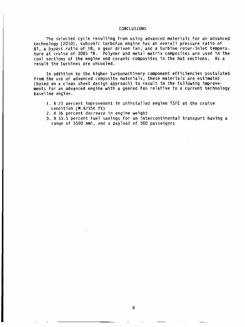
CONCLUSIONS
The selected cycle resulting from using advanced materials for an advanced technology (2010), subsonic turbofan engine has an overall pressure ratio of 87, a bypass ratio of 18, a gear driven fan, and a turbine rotor-inlet tempera- ture at cruise of 3085 O R . Polymer and metal matrlx composltes are used i n the cool sections of the englne and ceramic composites I n the hot sections. A s a result the turbines are uncooled.
In additlon to the higher turbomachinery component efficiencies postulated from the use of advanced composite materials, these materlals are estimated (based on a clean sheet design approach) to result i n the following improve- ments for an advanced engine with a geared fan relatlve to a current technology basellne englne.
1 . A 23 percent improvement in uninstalled engine TSFC at the cruise
2. A 36 percent decrease in engine weight 3. A 33.5 percent fuel savings for an lntercontinental transport having a
condition (M.8/35K ft)
range of 5500 nmi, and a payload of 500 passengers

REFERENCES
1. Gray, D.E. : Study of Turbofan Engines Designed f o r Low-Energy Consumption. (PWA-5318, P r a t t and Whitney A i r c r a f t ; NASA Cont rac t NAS3-19132) NASA CR-135002, 1976.
2. N e i t z e l , R.C.; H l rschkron, R.; and Johnston, R.F.: Study o f Turbofan Engines Designed f o r Low Energy Consumption. (R76AEG432, General E l e c t r i c Co.; NASA Cont rac t NAS3-19201) NASA CR-135053, 1976.
3. Knlp, G.: P re l im ina ry Study o f Advanced Turbofans f o r Low Energy Consump- t i o n . NASA TM X-71663, 1975.
4. Gray, D.E.; and Gardner, W.B.: Energy E f f i c i e n t Engine Program Technology Bene f i t /Cos t Study, Vol . 2, (PWA-5594-251-VOL-2, P r a t t and Whitney A i r - c r a f t ; NASA Cont rac t NAS3-20646) NASA CR-174766-VOL-2, 1983.
5. Gauntner, J.W.: A lgo r i t hm f o r C a l c u l a t i n g Turb ine Coo l ing Flow and t h e R e s u l t i n g Decrease I n Turb ine E f f i c i e n c y . NASA TM-81453, 1980.
6. Blecherman, S.S.; and Stankunas, T.M.: Composite Fan E x i t Guide Vanes f o r High Bypass R a t i o Gas Turb ine Engines. J. A i r c r . , v o l . 19, no. 12, Dec. 1982, pp. 1032-1037.
7. S t o l t z a , L.; and G r a f f , J . : Boron Aluminum Blades and Vanes. A I A A Paper 81-1359, J u l y 1981.
8. Gray, H.R.; Levlne, S.R.; and S l g n o r e l l i , R.A.: Turb ine Engine M a t e r i a l s . T a c t i c a l A i r c r a f t Research and Technology, Vol. 1, P t . 2, NASA CP-2162- VOL-1 -PT-2, 1981 , pp. 471 -494.
9. McDanels, D.L.; and Hoffman, C.A.: M i c r o s t r u c t u r e and O r i e n t a t i o n E f f e c t s on P roper t i es o f Discont inuous S i l i c o n Carbide/Aluminum Composites. NASA TP-2302, 1984.
10. Brooks, A. ; and B e l l i n , A . I . : Bene f i t s of Ceramics t o Gas Turb ines. Ceram- i c s f o r Turb ine Engine A p p l i c a t i o n s , AGARD-CP-276, AGARD, France, 1980.
11. S i g n o r e l l i , R.A.: High Temperature Composites - Sta tus and Future D i rec - t i o n s . Progress i n Science and Eng’ineering of Composites, T. Hayashi, K. Kawata, and S . Urnekawa, eds., North Hol land, 1982, pp. 37-48. (A lso , NASA TM-82929.)
12. D iCar lo , J.A.: High Performance F i b e r s f o r S t r u c t u r a l l y R e l i a b l e Meta l and Ceramic Composites. NASA TM-86878, 1984.
13. Fishbach, L.H.; and Caddy, M.J.: NNEP: The Navy-NASA Engine Program. NASA TM X-71857, 1975.
14. Onat, E. ; and Klees, G.W.: A Method t o Es t imate Weight and Dimensions o f Large and Small Gas Turb lne Engines. NASA CR-159481, 1979.
15. Gray, D.E. : Energy E f f i c i e n t Engine P r e l i m i n a r y Design and I n t e g r a t i o n Study. (PWA-5500-18, P r a t t and Whitney A l r c r a f t ; NASA Cont rac t NAS3-20628) NASA CR-135396, 1978.
9

TABLE I . - BASELINE TURBOFAN ENGINE
M 0.8/35 000 f t
Fan p ressu re r a t i o Bypass r a t i o Low p ressu re compressor P /P High p ressu re compressor P /P Combustor AP/P Turb ine r o t o r - i n l e t tempera ture , O R
Turb ine c o o l i n g a i r , p e r c e n t
1.65 7.2
1.84 14.0
0.044 2775
12
TABLE 11. - COMPARISON OF FLOW PATH PARAMETERS
Base l i ne
Fan H u b k i p r a t i o Blade s o l i d i t y F i r s t b lade AR Blade m a t e r i a l d e n s i t y Cor rec ted t i p v e l o c i t y , f p s Number o f r o t o r b lades Number o f stages
LPC H u b / t i p r a t i o Blade s o l i d i t y F i r s t b lade AR Maximum r o t o r speed, rpm Cor rec ted t i p v e l o c i t y , f p s Blade m a t e r i a l d e n s i t y Number o f r o t o r b lades Compressor des ign t y p e Number o f stages
HPC H u b k i p r a t i o Blade s o l i d i t y F i r s t b l a d e AR Max r o t o r speed, rpm Cor rec ted t i p v e l o c i t y , f p s Blade m a t e r i a l d e n s i t y Number o f r o t o r blades Compressor des ign t y p e Number o f stages
H PT Tu rb ine l o a d i n g parameter
gJ A H / N / V i Blade s o l i d i t y F i r s t b lade AR Blade m a t e r i a l d e n s i t y Number o f r o t o r b lades Tu rb ine des ign t y p e Number o f stages
Tu rb ine l o a d i n g parameter Blade s o l i d i t y F i r s t b lade AR Blade m a t e r i a l d e n s i t y Number o f r o t o r b lades Tu rb ine des ign t y p e Number o f stages
LPT
10
0.34 0.94
4 0.168
1444 35
1
0.82 1.1 2.4
3781 683
0.168 400
Const. hub r a d i u s 4
0.56 0.8 1.8
13 798 1285
0.3 827
Const. t i p r a d i u s 10
1 .ll
0.25 1.7 0.3
76 Const. mean r a d i u s
2
2.38 0.44
3 0.3 404
Const. hub r a d i u s 5
Advanced
0.26 0.94
3 0.05 1134
23 1
0.77 0.63
2.0 11 046
1723 0.05
74
2
0.49 0.8 1.8
20 212 1392 0.13
548 Const. mean r a d i u s
11
1.54
0.25 2
0.115 84
2
1.86 0.46
3 0.115
332
5
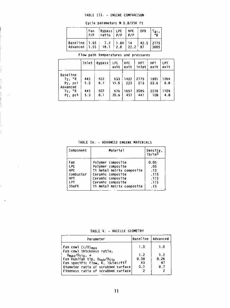
TABLE III. - ENGINE COMPARISON
Bypass
522 8.7
507 8.1
Cycle parameters M 0.8/35K f t
LPC HPC HPT e x i t e x i t i n l e t
633 1402 2775 15.9 223 213
676 1657 3085 20.6 457 441
Flow pa th temperatures and Pressures
Parameter
I n l e t
445 5.3
445 5.3
Base1 i n e
HPT e x i t
1901 53.6
2278 108
TABLE I V . - ADVANCED ENGINE MATERIALS
LPT ex1 t
1264 8.8
1109 4.8
Mater i a 1 I Component
Fan LPC HPC Combustor
S h a f t
Polymer composite Polymer composite T i me ta l ma t r l x composi te Ceramic composite Ceramic composite Ceramlc composite T i me ta l m a t r i x composi te
TABLE V . - NACELLE GEOMETRY
0.05 .05 -13 -115 .115 .115 .13
Fan cowl (L/D)max Fan co r1 th i ckness r a t i o ,
Dmax/Dtlpt Q 1.2 Fan hub/fan t i p , Dhub/Dtip I 0.38
43 i Fan s p e c i f i c f l ow , K, l b / s e c / f t 2 Diameter r a t i o o f scrubbed s u r f a c e Fineness r a t i o o f scrubbed s u r f a c e
Advanced
11
3500
0 CARBON-CARBON /
0 4000
2 a k 3000 W
F g 2000
s - I-
W
loo0
0 1 .ox106
STRENGTHNIGHT
FIGURE 1. - POSSIBLE ADVANCED MATERIALS FOR FUTURE TURBINE ENGINES.
"1 3500
/ CARBON-CARBON /
CERAMIC COMPOSITE 4 THERMAL BARRIER COATINGS7
,-FIBER- REINFORCED SUPERALLOY
DIRECT I ONAL STRUCTURES- - ODS SUPERALLOY
'-EUTECTICS
ALLY SOLIDIFIED
2400 W
%
2200
2000 I UDIMET 700
I I 1950 1960 1970 1980 1990 2000 2010
APPROXIMATE YEAR OF INTRODUCTION INTO ENGINE
FIGURE 3. - TEMPERATURE TRENDS OF TURBINE BLADE MATERIALS.
2. 3200 -
0"
d 3000 - a @z
c 4 @z W
-- ODs-NICRAL CONVENTIONALLY
0" 320T CERAMIC COMPOSITE H d 3000 @z
c 4 @z W
a
-- ODs-NICRAL 2600
CONVENTIONALLY TD-NICR
_/--
I I I 1950 1960 1970 1980 1990 2000 2010
APPROXIMATE YEAR OF INTRODUCTION INTO ENGINE
FIGURE 2. - TEMPERATURE TRENDS OF TURBINE VANE MATERIALS.
.45 - TURBINE
INLET TEMPERATURE.
FPR = 1 . 5 5 / 1 . 4 LPC. 3 A X I A L STAGES LPC PRESSURE R A T I O . 2 HPC.11 STAGES HPT. 2 STAGES
OR
2760 2885 - 3085
---- ---
w 3 LL
2 -42 - LL
a z .41 -
0 W
c v,
60 80 100
FIGURE 4. - EFFECT OF TURBINE ROTOR-INLET TERERATURE
.40 40
OVERALL PRESSURE RATIO, OPR
ON PERFORMANCE OF ADVANCED TURBOFAN AS FUNCTION OF OVERALL PRESSURE RATIO.
12
I 260 r
260
\ z Z Z O ~ / ,
LL
180
- 140 T41,
a BPR = OPTIMUM r W I UNCOOLED
LPC. 3 A X I A L STAGES LPC PRESSURE RATIO. 2 HPC. 11 A X I A L STAGES
140 4 40 50 60 70 80 90 100
OVERALL PRESSURE RATIO. OPR
FIGURE 5. - VARIATION I N ENGINE SPECIFIC THRUST WITH TURBINE ROTOR-INLET TEMPERATURE AS FUNCTION OF OVERALL PRESSURE RATIO.
FAN PRESSURE LPC. 3 A X I A L STAGES
HPC. 1 1 A X I A L STAGES RATIO LPC PRESSURE RATIO, 2
v L L I ~ ~~
HPT; 2 A X I A L STAGES LPT, 5 A X I A L STAGES T 4 1 = 3 0 8 5 "R OPR = 100
v) 5 0 sot c I \ \ UNCOOLED
2
3 LL w - 4 6
u v Y n v)
.38 8 12 16 20 24 28
FIGURE 7 . - OPTIMUM BYPASS RATIO I N TERMS OF ENGINE
BYPASS RATIO. BPR
PERFORMANCE FOR RANGE OF FAN PRESSURE RATIOS.
.38 40 50 60 70 80 90 100
OVERALL PRESSURE RATIO. OPR
FIGURE 6. - ENGINE PERFORMANCE VERSUS OVERALL PRESSURE RATIO FOR RANGE OF FAN PRESSURE RATIOS.
T LOW-PRESSURE
COMPRESSOR PRESSURE
RAT IO
FPR = 1 . 5 5 / 1 . 4 LPC. 3 A X I A L STAGES HPC. 1 1 A X I A L STAGES HPT, 2 A X I A L STAGES LPT. 5 A X I A L STAGES
\ T 4 1 = 3 0 8 5 "R OPR = 1 0 0 UNCOOLED
.40 4 12 14 16 18 20
BYPASS RATIO, BPR
FIGURE 8. - EFFECT OF PRESSURE RATIO FOR THREE-STAGE
MANCE. AXIAL LOW PRESSURE COMPRESSOR ON ENGINE PERFOR-
13

OVERALL PRESSURE PRESSURE
RATIO
HPC
.43 c RATIO
L
+ E: 4 .42 - ln L 0 u
_I W 3 L
FPP = 1 5 5 1 1 4
T a l - 3 0 8 5 O R
OPR = 100 BPR = OPTIMUM UNCOOLED
27.23 87
t; .41 e “ t ln
10 11 12 13 14 .40 9
NUMBER OF HPC STAGES
FIGURE 9. - VARIATION I N ENGINE PERFORMCE AS FUNCTION OF NUNBER OF HIGH-PRESSURE COM- PRESSOR STAGES.
.415
V
? r
+ E:
f Y
d .410
u k Y
Li
0 u
3 LL
n. ln
a p: I c
,405
HPT MEAN BLADE
VELOCITY,
UW FT/SEC
1580 --- 1600 -
FPR = 1 . 5 5 A . 4 LPC, 3 A X I A L STAGES LPC PRESSURE RATIO. 2.3 HPC. 11 A X I A L STAGES LPT. 5 A X I A L STAGES LPT BLADE MEAN VELOCITY. 930 f t l s e c T41 = 3085 O R
OPR = 81 BPR = OPTIMUM UNCOOLED
3 4 NUMBER OF HPT STAGES
FIGURE 11. - VARIATION I N ENGINE PERFORMANCE AS FUNCTION OF NUMBER OF HIGH-PRESSURE TURBINE STAGES AND MEAN BLADE VELOCITY.
1 FPR = 1 . 5 5 / 1 . 4 LPC. 3 A X I A L STAGES
*4! .42
LPC~PRESSURE RATIO, 2.3
HPT BLADE MEAN VELOCITY, 1 5 0 0 f t / s e c
LPT BLADE MEAN VELOCITY. 930 f t / s e c
HPT. 2 A X I A L STAGES
LPT. 5 A X I A L STAGES
T41 = 3 0 8 5 O R
DPR = E 1 EPR - OPTIMUM UNCDDLED
I
AXIAL NUMBER STAGES OF 1 I I
5 3
/ y-. ---.>e ‘ *A
0 4 8 12 16 CENTRIFUGAL PRESSURE RATIO
FIGURE 10. - EFFECT OF VARIOUS AXIAL-CENTRIFUGAL
- 4 1
HIGH-PRESSURE COMPRESSORS ON PERFORMCE OF ADVANCED TURBOFAN.
LPT MEAN
VELOCITY. - BLADE
UM, FT/SEC FPR = 1 . 5 5 / 1 . 4
LPC. 3 A X I A L STAGES 930 LPC PRESSURE RATIO, 2 - --- 1200 HPC. 1 1 A X I A L STAGES
HPT. 2 A X I A L STAGES HPT BLADE MEAN VELOCITY. 1500 f t l s e c T41 = 3085 ‘R OPR = 81 EPR - OPTIMUM UNCODLEO
-- ---- ---------- 6 7
FIGURE 12. - VARIATION I N ENGINE PERFORMANCE AS
NUMBER OF LPT STAGES
FUNCTION OF NUMBER OF LOW-PRESSURE TURBINE STAGES AND R A N BLADE VELOCITY.
14

60 -
50 -
40 -
5 30-
2 n 2 2 0 -
v)
10 -
NOZZLE
NOZZLE
LPC. 2 STAGES
LPC STAGE LOADING. 0 . 4 5 8
LPC T I P VELOCITY. 1 1 2 4
HPC, 1 1 STAGES
HPC STAGE LOADING, 0 . 1 4 1
HPC T I P VELOCITY. 1 3 9 2
HPT. 2 STAGES
HPT WORK FACTOR, 1 . 5 4
LPT. 5 STAGES
L P T WORK FACTOR. 1 . 8 6
50
40
30
z I
y 20
s - n
10
0
-10
20 40 60 80 100 120 140 160 LENGTH. IN.
FIGURE 13. - ADVANCED ENGINE FLOWPATH: TOTAL ENGINE WEIGHT. 4866 LB.
NOZZLE FAN
NOZZLE
I I 1 1 0 20 40 60 80 100 120 140 160 180
LENGTH. IN.
FIGURE 14. - BASELINE ENGINE FLOWPATH: TOTAL ENGINE WEIGHT. 6980 LB.
L w
.2 . 3 BLADE DENSITY, L B / I N . ~
FIGURE 15. - ADVANCED ENGINE WEIGHT VERSUS LOW- PRESSURE TURBINE BLADE DENSITY.
15

. 6 -
u
?
4 z
c E:
L .4 v)
0 u 2 W
L
-
a
u LL u W L v)
I- v) = = f . 2
kz r,
- n W 1 1 4
L a
W V
W n.
5 30 LL
CL 3 c W
1 W v)
P
z
2 2 0 - 0 c W z 5 1 w CL
v) W 4 1 0 - 4 v)
2 w 3 LL
0
BASELl NE ADVANCED
FIGURE 16. - UNINSTALLED TSFC COMPARISON FOR THE BASELINE AND THE ADVANCED TURBOFAN.
-
TSFC
/ ADVANCED
8000 -
6000 -
c r CI y 4000- W z
L W
I
2000 -
FIGURE 18. - ENGINE WEIGHT COMPARISON FOR BASELINE AND ADVANCED TURBOFAN.
------- BASEL 1 NE NACELLE - ADVANCED NACELLE
I I ------ ----_________-- ---- FIGURE 17. - COMPARISON OF ADVANCED AND BASELINE ENGINE NACELLE.
40 r
ENGINE
FIGURE 19. - ADVANCED ENGINE FUEL SAVING RELATIVE TO BASELINE TURBOFAN. MISSION: MACH 0.8; RANGE. 5500 N MI; PAYLOAD, 500 PASSENGERS.
16
APPtNDlX A
SYMBOL L I S T
A R BPR DHUB
DTIT F PR F N 9 H PC H PT J K L/D L PC LPT N OPR P / P , PR
DMAX
PT l!3 Tm 1 3 T4l TSFC Um VT WC
e
A H AP/P
Y n a
Subscripts
aspect ratio bypass ratio fan hub diameter, ft fan maximum cowl diameter, ft fan tip dlameter, ft fan pressure ratio; bypass/core engine net thrust, l b gravitational constant, ft/sec2 high pressure compressor hlgh pressure turbine mechanical equlvalent of heat, 778 ft-lb/BTU corrected flow per unit area, lb/sec-ft2 nacelle fineness ratio low pressure compressor low pressure turbine number of stages overall pressure ratio pressure rat70 total pressure, lb/in.2 hot gas temperature, O R
bulk metal temperature, O R
HPC exit temperature, O R
turbine ratio-inlet temperature, O R
thrust speclfic fuel consumption, lb/lb-hr mean blade velocity, ft/sec tlp velocity, ft/sec core airflow, 1 b/sec enthalpy change btu/lb pressure loss temperature/sea-level standard temperature ratio o f specific heats efficlency Dmax/DT I P
ad ad1 abat i c j stage ov overa 1 1 P polytropic
77
A P P E N D I X B
FLOWPATH STUDY
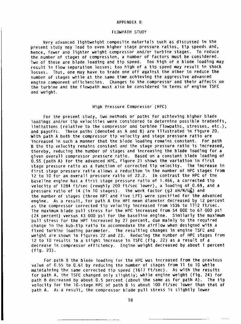
Very advanced l i g h t w e i g h t composite m a t e r i a l s such as d iscussed i n t h e p resen t study may lead t o even h ighe r s tage p ressu re r a t i o s , t i p speeds and, hence, fewer and l i g h t e r we igh t compressor and/or t u r b i n e s tages. To reduce t h e number of stages of compression, a number o f f a c t o r s must be cons idered. Two o f these a r e b lade l o a d i n g and t i p speed. r e s u l t i n f l o w separa t i on losses ; t o o h i g h o f a t i p speed may r e s u l t i n shock losses . Thus, one may have t o t r a d e one o f f a g a i n s t t h e o t h e r t o reduce t h e number o f stages w h i l e a t t h e same t i m e a c h i e v i n g t h e aggress ive advanced engine component e f f i c i e n c i e s . t h e t u r b i n e and t h e f l owpa th must a l s o be considered i n terms o f engine TSFC and we igh t .
Too h i g h o f a b lade l o a d i n g may
Changes t o t h e compressor and t h e i r a f f e c t s .on
High Pressure Compressor (HPC)
For the present s tudy, two methods o r paths f o r a c h i e v i n g h i g h e r b lade load ings and/or t i p v e l o c i t i e s were cons idered t o de termine p o s s i b l e t r a d e o f f s , l i m i t a t i o n s ( r e l a t i v e t o t h e compressor and t u r b i n e f lowpaths , s t resses , e t c . ) , and payo f f s . Wi th p a t h A b o t h t h e compressor t i p v e l o c i t y and s tage pressure r a t i o a r e inc reased i n such a manner t h a t t h e b lade l o a d i n g remains cons tan t . For p a t h B t h e t i p v e l o c i t y remains cons tan t and t h e s tage p ressu re r a t i o i s increased, thereby , reducing t h e number o f stages and i n c r e a s i n g t h e b lade l o a d i n g f o r a g i v e n o v e r a l l compressor p ressure r a t i o . Based on a cons tan t b lade l o a d i n g o f 0.55 ( p a t h A ) f o r t h e advanced HPC, f i g u r e 21 shows t h e v a r i a t i o n i n f i r s t s tage pressure r a t i o as a f u n c t i o n o f c o r r e c t e d t i p v e l o c i t y . The inc rease i n f i r s t stage pressure r a t i o a l l o w s a r e d u c t i o n i n t h e number o f HPC s tages f rom 12 t o 10 f o r an o v e r a l l p ressure r a t i o o f 22.2. b a s e l i n e engine has a f i r s t s tage pressure r a t i o o f 1.466, a c o r r e c t e d t i p v e l o c i t y of 1284 f t / s e c ( r o u g h l y 200 f t / s e c lower ) , a l o a d i n g o f 0.69, and a pressure r a t i o o f 14 ( i n 10 s tages ) . t h e number o f stages ( t h r e e HPT and f i v e LPT) were s p e c i f i e d f o r t h e advanced engine. A s a r e s u l t , f o r p a t h A t h e HPT mean d lameter decreased by 12 pe rcen t as t h e compressor co r rec ted t i p v e l o c i t y inc reased f rom 1536 t o 1712 f t / s e c . The maximum b lade p u l l s t r e s s f o r t h e HPC inc reased f rom 54 000 t o 67 000 p s i ( 2 4 percent ) versus 43 000 p s i f o r t h e b a s e l i n e engine. S i m i l a r l y t h e maximum p u l l s t ress f o r t h e HPT inc reased by 27 percent , due ma in l y t o t h e r e q u i r e d change i n the h u b - t i p r a t i o t o accommodate t h e a i r f l o w when designed w i t h a f i x e d t u r b i n e l o a d i n g parameter. The r e s u l t i n g changes i n engine TSFC and we igh t a r e shown i n f i g u r e s 22 and 23. Reducing t h e number o f HPC stages f rom 12 t o 10 r e s u l t s i n a s l i g h t i nc rease i n TSFC ( f i g . 22) as a r e s u l t o f a decrease i n compressor e f f l c i e n c y . Engine we igh t decreased by about 1 pe rcen t ( f i g . 23) .
These paths (denoted as A and 8) a r e i l l u s t r a t e d i n f i g u r e 20.
I n c o n t r a s t t h e HPC o f t h e
The work f a c t o r ( g J AH/N/U$) and
For path B t h e b lade l o a d i n g f o r t h e HPC was increased f rom t h e p rev ious va lue of 0.55 t o 0.61 by reduc ing t h e number o f stages f rom 11 t o 10 w h i l e m a i n t a i n i n g t h e same c o r r e c t e d t l p speed (1617 f t / s e c ) . A s w i t h t h e r e s u l t s f o r p a t h A, t h e TSFC changed o n l y s l i g h t l y ; w h i l e engine we igh t ( f i g . 24) f o r p a t h B decreased by about 0.5 percent (about t h e same as f o r p a t h A ) . The t i p v e l o c i t y f o r t h e 10-stage HPC of p a t h B i s about 100 f t / s e c lower than t h a t o f p a t h A . A s a r e s u l t , t h e compressor b lade p u l l s t r e s s i s s l i g h t l y lower
18
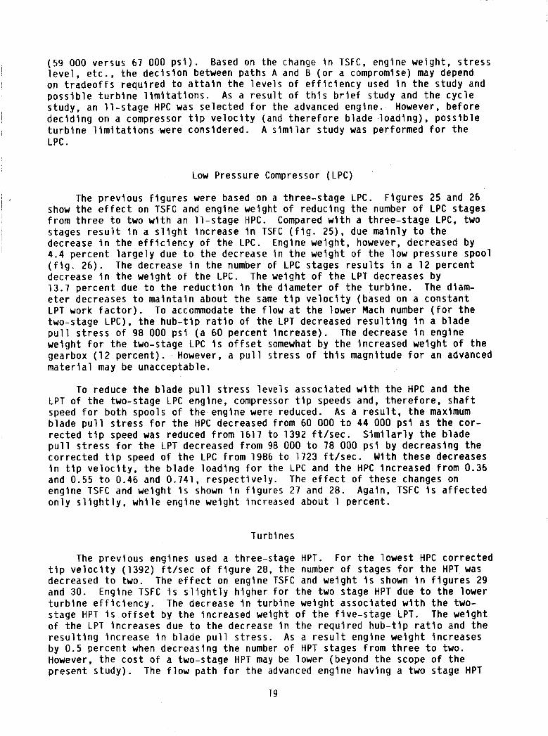
(59 000 versus 67 000 p s i ) . Based on the change I n TSFC, engine we igh t , s t r e s s l e v e l , e t c . , t h e d e c i s i o n between paths A and 6 ( o r a compromise) may depend on t r a d e o f f s r e q u i r e d t o a t t a i n t h e l e v e l s o f e f f i c i e n c y used i n t h e study and p o s s i b l e t u r b i n e l i m i t a t i o n s . As a r e s u l t o f t h i s b r i e f study and t h e c y c l e study, an l l - s t a g e HPC was se lec ted f o r the advanced engine. However, b e f o r e d e c i d i n g on a compressor t i p v e l o c i t y (and t h e r e f o r e b lade l o a d i n g ) , p o s s i b l e t u r b i n e l i m i t a t i o n s were considered. A s i m i l a r s tudy was performed f o r the LPC.
Low Pressure Compressor (LPC)
The p rev ious f i g u r e s were based on a th ree-s tage LPC. F igures 25 and 26 show t h e e f f e c t on TSFC and engine weight o f reduc ing t h e number o f LPC stages
stages r e s u l t i n a s l i g h t i nc rease i n TSFC ( f i g . 25). due ma in l y t o the decrease i n t h e e f f i c i e n c y o f t h e LPC. Engine weight, however, decreased by 4.4 pe rcen t l a r g e l y due t o t h e decrease i n t h e we igh t o f t he low pressure spool ( f i g . 26). The decrease i n t h e number o f LPC stages r e s u l t s i n a 12 pe rcen t decrease i n t h e we igh t o f t h e LPC. 13.7 p e r c e n t due t o t h e r e d u c t i o n i n t h e dlameter o f t h e t u r b i n e . The diam- e t e r decreases t o m a i n t a i n about the same t i p v e l o c i t y (based on a cons tan t LPT work f a c t o r ) . To accommodate t h e f l o w a t t h e lower Mach number ( f o r t h e two-stage LPC), t h e h u b - t i p r a t i o o f t he LPT decreased r e s u l t i n g i n a b lade p u l l s t r e s s o f 98 000 p s i ( a 60 pe rcen t i nc rease ) . The decrease i n engine we igh t f o r t h e two-stage LPC i s o f f s e t somewhat by t h e inc reased we igh t o f t h e gearbox ( 1 2 pe rcen t ) . m a t e r i a l may be unacceptable.
I f rom t h r e e t o two w i t h an l l - s t a g e HPC. Compared w i t h a th ree-s tage LPC, two
i
I ’
I
The we igh t o f t h e LPT decreases by
However, a p u l l s t ress o f t h i s magnitude f o r an advanced
To reduce t h e b lade p u l l s t r e s s l e v e l s assoc ia ted w i t h t h e HPC and t h e
As a r e s u l t , t h e maximum
S i m i l a r l y t h e b lade
LPT o f t h e two-stage LPC engine, compressor t i p speeds and, t h e r e f o r e , s h a f t speed f o r b o t h spools o f t h e engine were reduced. b lade p u l l s t r e s s f o r t h e HPC decreased from 60 000 t o 44 000 p s i as the c o r - r e c t e d t i p speed was reduced f rom 1617 t o 1392 f t / s e c . p u l l s t r e s s f o r t h e LPT decreased f rom 98 000 t o 78 000 p s i by decreas ing t h e c o r r e c t e d t i p speed o f t h e LPC f rom 1986 t o 1723 f t / s e c . With these decreases i n t i p v e l o c i t y , t h e b lade l o a d i n g f o r the LPC and t h e HPC increased f rom 0.36 and 0.55 t o 0.46 and 0.741, r e s p e c t i v e l y . The e f f e c t o f these changes on engine TSFC and we igh t i s shown i n f i g u r e s 27 and 28. Again, TSFC i s a f f e c t e d o n l y s l i g h t l y , w h i l e engine we igh t increased about 1 percent .
Turbines
The p rev ious engines used a three-stage HPT. For the lowes t HPC c o r r e c t e d t i p v e l o c i t y (1392) f t / s e c o f f i g u r e 28, t h e number o f stages f o r t h e HPT was decreased t o two. The e f f e c t on engine TSFC and we igh t i s shown i n f i g u r e s 29 and 30. Engine TSFC i s s l i g h t l y h ighe r f o r t h e t w o stage HPT due t o t h e lower t u r b i n e e f f i c i e n c y . The decrease i n t u r b i n e we igh t assoc ia ted w i t h t h e two- stage HPT i s o f f s e t by t h e increased weight o f t h e f i v e - s t a g e LPT. The we igh t o f t h e LPT increases due t o t h e decrease i n t h e r e q u i r e d h u b - t i p r a t i o and t h e r e s u l t i n g i nc rease i n b lade p u l l s t r e s s . As a r e s u l t engine we igh t inc reases by 0.5 percent when decreas ing t h e number o f HPT stages f rom t h r e e t o two. However, t h e c o s t o f a two-stage HPT may be lower (beyond t h e scope o f t h e present s t u d y ) . The f l o w pa th f o r t h e advanced engine hav ing a two stage HPT
19

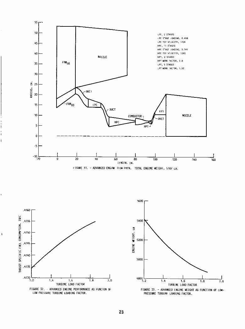
i s shown i n f i g u r e 31. The engine has a maximum diameter o f 106 i n . and i s 110 i n . l ong up t o t h e e x i t of t h e LPT and 152 i n . o v e r a l l t o t h e e x i t o f t h e nozz le . Engine weight i nc ludes a l l of t h e components shown i n t h e f i g u r e p l u s t h e gearbox.
1.6
0 d +
W E 3 v) v) W
1.5 W W
v) 5 z 3 LL
To reduce t h e displacement between t h e HPT and t h e LPT, t h e l o a d i n g Th is inc reased t h e t i p
A s a r e s u l t t h e e x i t t i p rad ius inc reased parameter f o r t h e HPT was decreased f rom 2.0 t o 1.54. v e l o c i t y f rom 1275 t o 1460 f t / s e c . by about 1 i n . To f u r t h e r reduce t h e l e n g t h o f t h e t r a n s i t i o n duc t , t h e load- i n g parameter f o r t h e LPT was increased from 1.52 t o 1.86 which r e s u l t s i n on l y a 0.5 percent i nc rease i n TSFC ( f i g . 32), b u t an 1 1 - p e r c e n t decrease i n engine weight ( f i g . 33).
-
-
i I NCREASING
, HIGH-PRESSURE ROTOR T I P VELOCITY, FT/SEC
FIGURE 20. - COMPRESSOR STAGE PRESSURE RATIO TRENDS AS FUNCTION OF ROTOR T I P VELOCITY FOR RANGE OF BLADE LOADINGS.
FPR = 1 . 5 5 / 1 . 4 LPC. 3 A X I A L STAGES LPC PRESSURE R A T I O . 2 . 8
A w . I
HPC. 3 AXIAL STAGES HPC PRESSURE R A T I O , 22 .2 T 4 l = 3085 " R HPT, 3 STAGES LPT. 5 STAGES
F .41 I
10 11 12 NUMBER OF HPC STAGES
FIGURE 22. - ADVANCED ENGINE PERFORMANCE VERSUS NUMBER OF HIGH-PRESSURE CONPRESSOR STAGES. BLADE LOADING FOR LPC. 0.38: FOR HPC. 0.55.
NOTE:
BASELINE ENGINE (P/PIlsT = 1.466
U T / f i = 1284
1 .4 1500 1600 1700 1800
CORRECTED T I P VELOCITY. FT/SEC
FIGURE 21. - ADVANCED AXIAL COMPRESSOR STAGE PRES- SURE RATIO VERSUS CORRECTED T I P VELOCITY. STAGE BLADE LOADING I N HPC, 0.55: HPC PRESSURE RATIO, 22.2.
FIRST
5300 r m
LPC. 3 A X I A L STAGES 5 0
5200 t W z
z E l W
LPC.PRESSURE RATIO, 2 . 8 HPC. 3 A X I A L STAGES HPC'PRESSURE R A T ~ O , 2 2 . 2 T 4 i = 3085 'R H P T , 3 STAGES L P T , 5 STAGES
11 12 5100
10 NUMBER OF HPC STAGES
FIGURE 23. - ADVANCE0 ENGINE WEIGHT VERSUS NUMBER OF HIGH-PRESSURE COMPRESSOR STAGES. BLADE LOADING FOR LPC. 0.38: FOR HPC. 0.55.
20

5 3 ~
BLADE LOAD1 NG
0.55
FPR = 1 . 5 5 / 1 . 4
LPC. 3 A X I A L STAGES
LPC PRESSURE RATIO, 2 . 8
T~~ = 3 0 8 5 O R
11 10 NUMBER OF HPC STAGES
FIGURE 211. - ADVANCED ENGINE WEIGHT VERSUS NUMBER OF HIGH-PRESSURE COMPRESSOR STAGES FOR CONSTANT CORRECTED T IP VELOCITY.
5300 FPR = 1 . 5 5 / 1 . 4
HPC, 11 STAGES
HPC PRESSURE R A T I O , 22.2
H P T , 3 STAGES
L P T . 5 STAGES
~ 4 1 = 3 0 8 5 'R
5 5200
E Y L,
c 1
W
0 L
5100
5000 3 2 NUMBER OF LPC STAGES
FIGURE 26. - EFFECT ON ENGINE WEIGHT OF REDUCING THE NUMBER OF LOU-PRESSURE STAGES OF THE ADVANCED ENGINE.
.415
FPR = 1 . 5 5 / 1 . 4
HPC, 1 1 STAGES
HPC PRESSURE RATIO. 2 2 . 2
HPT. 3 STAGES
LPT. 5 STAGES
iel = 3 0 8 5 *R
OPR = e 7
-
NUMBER OF LPC STAGES
FIGURE 25. - EFFECT ON ENGINE TSFC OF RE- DUCING THE NUMBER OF LOU-PRESSURE COM- PRESSOR STAGES OF ADVANCED ENGINE.
LPC. 2 STAGES
HPC. 1 1 STAGES
HPT. 3 STAGES
LPT. 5 STAGES
. . . 1300 11100 1500 1600
HPC CORRECTED T I P VELOCITY, FT/SEC
FIGURE 27. - ADVANCED ENGINE PERFORMANCE AS FUNCTION OF CORRECTED T I P VELOCITY FOR HIGH-PRESSURE COMPRESSOR. CONSTANT STAGE PRESSURE RATIO.
21

LPC, 2 STAGES
HPC, 11 STAGES
L P T , 5 STAGES
5150
5100 m
$ 2 g 5050 L W
W r
.
- LPC. 2 STAGES
HPC, 11 STAGES
HPT, 3 STAGES
- L P T . 5 STAGES
w \ 5000 1300 1400 1500 1600 1700
HPC CORRECTED T I P VELOCITY. FT/SEC
FIGURE 28. - ADVANCED ENGINE WEIGHT AS FUNCTION OF CORRECTED T I P VELOCITY FOR THE HIGH-PRESSURE COMPRESSOR WITH CONSTANT STAGE PRESSURE RATIO.
3 NUNBER OF HPT STAGES
FIGURE 29. - EFFECT ON TSFC OF DECREASING NUMBER OF HIGH-PRESSURE TURBINE STAGES OF ADVANCED ENGINE.
LPC. 2 STAGES
HPC, 1 1 STAGES
L P T , 5 STAGES
2 5100
E Y E
E 5050
+ I
W
W
3 5000
2 NUMBER OF HPT STAGES
FIGURE 30. - EFFECT ON ADVANCED ENGINE HEIGHT OF DECREASING ThL NUNBER OF HIGH-PRESSURE TURBINE STAGES.
22
55
50
45
40
35
30
5 25
5 20 c*
15
10
5
0
-5
-10,
a q i 6 ~ r V LL v)
e .4155
c CI.
v) z 0 u
f .4150
.4145 3 LL
u $ .4140 W 5 v)
FANOD
NOZZLE
LPC. 2 STAGES
LPC STAGE LOADING. 0 . 4 5 8
LPC T I P V E L O C I T Y , 1 1 2 4
w c . 1 1 STAGES
n P c TIP VELOCITY. 1393
HPC STAGE LOAOING. 0 . 1 4 1
H P T , 2 STAGES
HPT WORK FACTOR, 2 . 0
L P T , 5 STAGES
L P T WORK FACTOR. 1 . 5 2
. NOZZLE
I 20 40 60 80 100 120 140 160 0
LENGTH, IN.
FIGURE 3 1 . - ADVANCED ENGINE FLOM PATH. TOTAL ENGINE WEIGHT, 5107 LB.
.4130 1 .2 1 .4 1 . 6 1 .8 2.0
TURBINE LOAD FACTOR
FIGURE 32. - ADVANCED ENGINE PERFORMANCE AS FUNCTON OF LOW-PRESSURE TURBINE LOADING FACTOR.
4 8 0 0 1 . 2 1 . 4 1.6 1 . 8 2.0
TURBINE LOAD FACTOR
FIGURE 3 3 . - ADVANCED ENGINE WEIGHT AS FUNCTION OF LOW- PRESSURE TURBINE LOADING FACTOR.
23
2 Government Accession No 1 _________
1 Report No.
._ ~ -- NASA TM- 89868
- 4 1INo illltl sllt~lill~l
7 Key Words (Suggeslod b y Author@))
Ana lys ls o f an Advanced Technology Subsanlc Turbofan Zncorporat lng Revo lu t i ona ry M a t e r i a l s
18. Distribution Statement
7. Author@)
Gera ld Knlp, Jr.
9 Security Classif (of thls report)
Unc 1 ass l f I ed
9. Performing Organization Name and Address
N a t l o n a l Aeronaut ics and Space A d m l n i s t r a t l o n Lewls Research Center Cleveland, Ohio 44135
20 Security Classif (of this page) 21 No of pages 22 Price'
U n c l a s s l f l e d 23 A02
2. Sponsoring Agency Name and Address
N a t l o n a l Aeronaut ics and Space A d m l n l s t r a t l o n Washlngton, D.C . 20546
- 5. Supplementary Notes
3. Recipient's Catalog No.
5. Report Date
May 1987
50 5- 69 - 4 1 6. Performlng Organization Code
8. Performing Organlzation Report NO.
E-3542
10. Work Unit No.
11. Contract or Grant No.
13. Type of Rep% and-Period Covered
Techn ica l Memorandum
14. Sponsoring Agency Code
6 Abstract
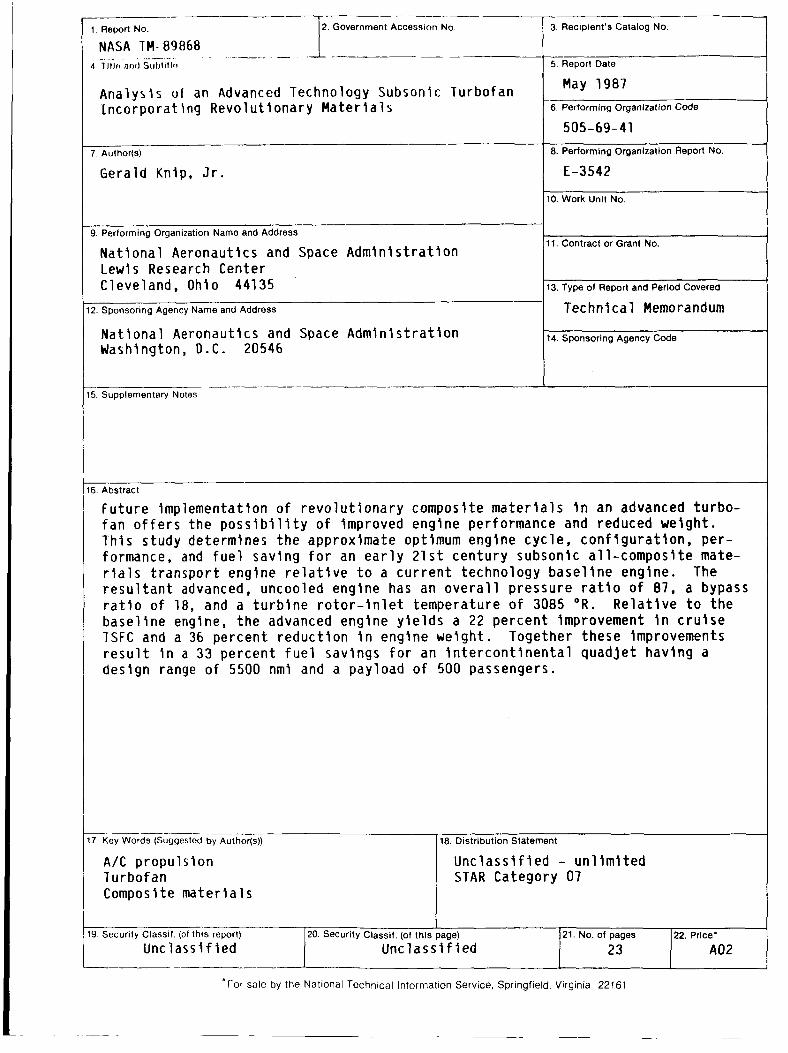
Fu tu re Implementat ion o f r e v o l u t i o n a r y composlte m a t e r i a l s i n an advanced tu rbo - f a n o f f e r s t h e p o s s l b l l l t y o f Improved engine performance and reduced we lgh t . Th is s tudy determines t h e approx imate optimum engine cyc le , c o n f i g u r a t i o n , per - formance, and f u e l sav lng f o r an e a r l y 21s t cen tu ry subsonic a l l - compos i te mate- rials t r a n s p o r t engine r e l a t l v e t o a c u r r e n t technology b a s e l l n e engine. r e s u l t a n t advanced, uncooled engine has an o v e r a l l p ressure r a t i o o f 87, a bypass r a t i o o f 18, and a t u r b i n e r o t o r - i n l e t temperature o f 3085 O R .
base l i ne englne, t h e advanced engine y l e l d s a 22 pe rcen t improvement I n c r u l s e TSFC and a 36 percent r e d u c t l o n i n engine we lgh t . Together these improvements r e s u l t I n a 33 percent f u e l sav lngs f o r an l n t e r c o n t i n e n t a l quad je t hav ing a des ign range o f 5500 nml and a pay load o f 500 passengers.
The
R e l a t i v e t o t h e
A / C p ropu ls lon Turbofan Compos 1 t e mater l a1 s
U n c l a s s i f i e d - u n l i m i t e d STAR Category 07