an introduction to accol (d4056) - emerson · an introduction to: ... there are bristol babcock...
TRANSCRIPT

PI
D
DEVICE
INITIAL
A n I n t r o d u c t i o n t o :
A C C O L( F o r m e r l y k n o w n a s " T h e A C C O L T e x t b o o k " )
�������������
D4056 Issue: January, 2001

The information in this document is subject to change without notice. Every effort has beenmade to supply complete and accurate information. However, Bristol Babcock assumes noresponsibility for any errors that may appear in this document.
Bristol Babcock does not guarantee the accuracy, sufficiency or suitability of the softwaredelivered herewith. The Customer shall inspect and test such software and other materials tohis/her satisfaction before using them with important data.
There are no warranties, expressed or implied, including those of merchantability and fitnessfor a particular purpose, concerning the software and other materials delivered herewith.
Request for Additional Instructions
Additional copies of instruction manuals may be ordered from the address below per attentionof the Sales Order Processing Department. List the instruction book numbers or give thecomplete model, serial or software version number. Furnish a return address that includesthe name of the person who will receive the material. Billing for extra copies will be accordingto current pricing schedules.
ACCOL is a trademark and Bristol is a registered trademark of Bristol Babcock. Othertrademarks or copyrighted products mentioned in this document are for information only, andbelong to their respective companies, or trademark holders.
Copyright (c) 2001, Bristol Babcock, 1100 Buckingham St., Watertown, CT 06795. No part ofthis manual may be reproduced in any form without the express written permission of BristolBabcock.
NoticeCopyright Notice

i
A Few Words About Bristol Babcock
For over 100 years, Bristol® has been providing innovative solutions for the measurementand control industry. Our product lines range from simple analog chart recorders, tosophisticated digital remote process controllers and flow computers, all the way to turnkeySCADA systems. Over the years, we have become a leading supplier to the electronic gasmeasurement, water purification, and wastewater treatment industries.
On off-shore oil platforms, on natural gas pipelines, and maybe even at your local watercompany, there are Bristol Babcock instruments, controllers, and systems running year-inand year-out to provide accurate and timely data to our customers.
Getting Additional Information
In addition to the information contained in this manual, you may receive additionalassistance in using Bristol Babcock products from the following sources:
Contacting Bristol Babcock Directly
Bristol Babcock's world headquarters are located at 1100 Buckingham Street, Watertown,Connecticut 06795, U.S.A. Our main phone numbers are:
(860) 945-2200(860) 945-2213 (FAX)
Regular office hours are Monday through Friday, 8:00AM to 4:30PM Eastern Time, excludingholidays and scheduled factory shutdowns. During other hours, callers may leave messagesusing Bristol's voice mail system.
Telephone Support - Technical Questions
During regular business hours, Bristol Babcock's Application Support Group can providetelephone support for your technical questions.
For technical questions regarding ACCOL, ACCOL Workbench, Open BSI products(as well as ACCOL DOS-based Tools, or UOI) call (860) 945-2286. Before you call,please find out the version of software you are using.
For technical questions regarding Bristol's OpenEnterprise product, call (860) 945-2501 ore-mail [email protected]
For technical questions regarding Bristol's Enterprise Server® / EnterpriseWorkstation® products, call (860) 945-2286.
For technical questions regarding Network 3000 hardware products call (860) 945-2502.
For technical questions about ControlWave call (860) 945-2244 or (860) 945-2286.
You can e-mail the Application Support Group at: [email protected]
The Application Support Group also maintains a bulletin board for downloading softwareupdates to customers. To access the bulletin board, dial (860) 945-2251 (Modem settings:14.4K baud maximum, No parity, 8 data bits, 1 Stop bit.)

ii
For assistance in interfacing Bristol Babcock hardware to radios, contact CommunicationTechnologies in Orlando, FL at (407) 629-9463 or (407) 629-9464.
Telephone Support - Non-Technical Questions, Product Orders, etc.
Questions of a non-technical nature (product orders, literature requests, price and deliveryinformation, etc.) should be directed to the nearest regional sales office (listed below) or toyour local Bristol sales office or Bristol-authorized sales representative.
U.S. Regional Sales Offices Principal International Sales Offices: Northeast (Watertown) (860) 945-2262 Bristol Babcock Ltd (UK): (441) 562-820-001Southeast (Birmingham) (205) 980-2010 Bristol Babcock, Canada: (416) 675-3820Midwest (Chicago) (630) 571-6052 Bristol Meci SA (France): (33) 2-5421-4074Western (Los Angeles) (909) 923-8488 Bristol Digital Sys. Australasia Pty. Ltd. 61 8-9455-9955Southwest (Houston) (713) 685-6200 BBI, S.A. de C.V. (Mexico) (525) 254-2131
Please call the main Bristol Babcock number (860-945-2200) if you are unsure which officecovers your particular area.
Visit our Site on the World Wide Web
For general information about Bristol Babcock and its products, please visit our site on theWorld Wide Web at: www.bristolbabcock.com
Training Courses
Bristol Babcock’s Training Department offers a wide variety of courses in Bristol hardwareand software at our Watertown, Connecticut headquarters, and at selected Bristol regionaloffices, throughout the year. Contact our Training Department at (860) 945-2343 for courseinformation, enrollment, pricing, and schedules.
iii
Who Should Read This Manual?
This manual is intended for use by new ACCOL users. It describes the basicconcepts in ACCOL, and provides examples of the major structures used by theACCOL programmer.
It assumes familiarity with the following subjects:
� Use of personal computers, including clicking with a mouse, using dialogboxes, list boxes, menus, etc.
� Windows 98 or Windows NT operating system.
As a minimum, users should have the following additional manuals available, whenreading this manual:
� ACCOL II Reference Manual (document# D4044) which contains detaileddescriptions of all ACCOL modules.
� ACCOL Workbench User Manual (document# D4051) which contains detailedinstructions on using ACCOL Workbench to create an ACCOL load.
� Network 3000 Communications Configuration Guide (document# D5080)which contains an overview of communications using Bristol Babcocknetworks, and a guide to troubleshooting communication problems.
NOTE
This book should not be considered a substitute for ’hands-on’ experience with ACCOL Workbench and Network 3000controllers.
New users should strongly consider attending one or moretraining courses offered by Bristol Babcock. Contact ourTraining Department at the number listed on page ii formore information.

BLANK PAGE

Table of Contents
v
Chapter 1 - What is ACCOL? ..................................................................................... 1-1
Chapter 2 - What Are Signals? .................................................................................. 2-1
Chapter 3 - What Are Modules?................................................................................. 3-1
Chapter 4 - What Are ACCOL Tasks? ....................................................................... 4-1
Chapter 5 - What Are Data Arrays? .......................................................................... 5-1
Chapter 6 - What Is Process I/O? ............................................................................... 6-1
Chapter 7 - How Are Communication Ports Used?................................................... 7-1
Chapter 8 - What Should I Know About Memory? ................................................... 8-1
Chapter 9 - What Are Signal Lists?........................................................................... 9-1
Chapter 10 - What Are Archive Files?..................................................................... 10-1
Appendix A - Creating A Sample ACCOL Load....................................................... A-1
Appendix B - Working with Floating Point Numbers.............................................. B-1
Glossary...................................................................................................................... G-1

BLANK PAGE

Chapter 1 - Introduction: What is ACCOL?
An Introduction to ACCOL Page 1-1
What is ACCOL?
ACCOL is an acronym which stands forAdvanced Communications and Control-Oriented Language. The initial concept forACCOL was developed at Bristol in theearly 1970s, and has since become thestandard software programming languagefor Bristol Babcock Network 3000-seriesdevices. Several newer generations of thelanguage have been developed since then.
The current versions of the ACCOLlanguage, as well as the ACCOL Toolssoftware, which is used to create programsin the language, have incorporatednumerous features and improvementssuggested by our customers, and aremarkedly different from the initial version.All are rooted in the initial concept ofACCOL, however, which was to create ahigh-level programming language whichused a ‘modular’ approach for monitoringand control of process control applications.
What is Network 3000?
Network 3000 is the name for a product family of Bristol Babcock digital remoteprocess controllers, and auxiliary equipment, which includes the DPC 3330, DPC3335, RTU 3310, and RTU 3305 remote process controllers, as well as GFC 3308-seriesflow computers1 and the EGM 3530-xx TeleFlow™ / RTU 3530-xx TeleRTU series2 flowcomputers and RTUs. Network 3000-series controllers are utilized in a wide variety ofmeasurement and control applications throughout the water, waste water, and naturalgas pipeline industries.
These controllers collect data from field instrumentation such as pressure transmitters,flow meters, electrical contacts and switches. The incoming data is received throughconnection points on process I/O boards in the controller.3 Based on the incoming data, 1 Network 3000 controllers are often referred to as simply ’33xx controllers’ because of the ’33’ in the model number.
2 3530 TeleFlow and TeleRTU units only support a subset of ACCOL modules and features. Task slipcounts and rate information, communication statistics, and crash blocks are not available. See the ACCOLII Reference Manual (D4044) and contact Bristol Babcock Application Support for more information.3 The term ‘I/O’ is an abbreviation for input/output and refers to data coming in, and going out, of a particulardevice. The ‘Process I/O board’ is an electronic device (board/card) in the controller through which data comes in andout from field instrumentation (the process).

Chapter 1 - Introduction: What is ACCOL?
Page 1-2 An Introduction to ACCOL
the controllers can execute pre-programmed instructions to control a process.
For example, in response to data collected from field instruments, the controller canissue commands to open valves when a certain pressure is reached, or to startcompressors or pumps if a flow rate decreases below setpoint. All of these pre-programmed instructions are written using ACCOL.
In addition to directly controlling a process, a Network 3000 controller can serve as anode in a communications network. Each controller (node) can thus share its data withother controllers.
Data is sent to the network through one or more of the controller’s communicationports. If controllers are located near each other, network connections can be ‘hard-wired’with cables. Controllers which are far away can communicate through dial-up modemsusing either dedicated phone lines or the public telephone system. For some applications,radio or satellite links may be appropriate.
Typically, one or more PC workstations is also connected to the network. Theseworkstations generally include ACCOL Tools software to allow for ACCOLprogramming, as well as Open Bristol System Interface (BSI) Utilities software. TheOpen BSI Utilities are a collection of programs which facilitate communication with thecontroller network by the ACCOL Tools, and by third-party applications. Open BSIUtilities also allow an operator to collect and view data from the network, and to monitorthe status of network communications. Separate utilities may be purchased which allowscheduled data collection, and file export capability to third-party applications such asMicrosoft Excel spreadsheets or data bases such as Microsoft Access.
Often, the PC workstations are also equipped with Supervisory Control and DataAcquisition (SCADA) or Human-Machine Interface (HMI) software packages whichallow the presentation of data to an operator in the form of graphical displays, trends,and printed logs or reports. The PC workstation can use one of several different packagesfor this purpose including Iconics Genesis software, Intellution® FIX® software, orBristol Babcock’s own OpenEnterprise software.

Chapter 1 - Introduction: What is ACCOL?
An Introduction to ACCOL Page 1-3
How Are the Controllers Programmed?
ACCOL programming is done using a set of software programs referred to as theACCOL Tools. The most important program in the ACCOL Tools software set isACCOL Workbench. ACCOL Workbench, is a Windows-based tool which combines thenecessary functions for ACCOL program generation, with the cut, paste, search, andreplace capabilities of a text editor.
The ACCOL programmer uses ACCOL Workbench to construct an ACCOL source file.4
The ACCOL source file consists of ASCII text, and has a file extension of (.ACC).
When editing the source file, the programmer selects from a large set of pre-programmedACCOL software module templates and control statements which can be inserted inthe source file. These modules and statements perform common mathematical,communication, and process control functions.5
Each module receives a series of inputvalues, upon which it performscertain calculations. It then generatesa series of output values which maybe used by other modules. Forexample, the PID3TERM modulegenerates outputs which allowproportional, integral, and derivativecontrol over an input value.
Each module includes a set of module terminals which are used to specify the inputsand outputs of the module. The name of an ACCOL signal or, in some cases, just anumerical value, is entered on the required module terminals. Signals are softwarestructures which allow data to be passed between modules.6 Each signal has a specificname which should reflect the type of data it holds. For example, if a signal is used tostore the level of water in water tank number 3, the signal should have a name such asTANK3.WATER.LEVL. Each signal name, as well as certain characteristics associatedwith the signal such as its initial value, engineering units, etc. must be defined in theACCOL source file. A typical ACCOL source file includes several hundred signals;however, depending upon the complexity of the system, thousands of signals may beused. 4 The ACCOL source file can also be edited directly with any ASCII text editor. AccolCAD software, available separately
from Bristol Babcock, can also be used to generate the ACCOL source file. Notes For Older Network 3000 Products:Different methods for program generation exist for older model controllers; these units use an older DOS-based set ofACCOL Tools which include the ACCOL II Batch Compiler (ABC) and ACCOL II Interactive Compiler (AIC). Theseolder tools are not discussed in this manual. 5 There are numerous modules and control statements to choose from. For information on particular modules andcontrol statements see the ACCOL II Reference Manual (document# D4044).6 For users familiar with other high-level programming languages such as BASIC or ‘C’, signals can be thought of as‘variables’. In some industries, they are referred to as ‘tags’.

Chapter 1 - Introduction: What is ACCOL?
Page 1-4 An Introduction to ACCOL
By entering the same signal name on terminals of different modules, a connectionbetween the modules is established, and the modules are said to be ‘wired’ together.7 Inthis way, the output of one module serves as the input to another module; allowing datavalues to be shared between modules.
The programmer combines the appropriate modules and control statements together intofunctional blocks called ACCOL Tasks. ACCOL tasks provide a way to divide up thesource file, and make it more manageable. Although an ACCOL source file cantheoretically include more than 100 tasks, most ACCOL programmers find that using afew tasks, say less than ten, is most efficient. Each ACCOL task executes at a user-defined rate, and with a user-defined priority. In this way tasks which perform criticalprocess control operations can take precedence over tasks which perform less importantcalculations.
The ACCOL source file may include other structures which allow for data storage andmanagement, such as signal lists and data arrays. These subjects will be discussedlater in this manual.
7 The modules, terminals, signals, and the connections between them all exist in the software program which executes inthe controller. There are no physical modules to be wired together. Unless otherwise noted, whenever these terms areused in this book, they refer to software structures in the ACCOL, not physical hardware devices.

Chapter 1 - Introduction: What is ACCOL?
An Introduction to ACCOL Page 1-5
Once the ACCOL source file has been completed,it must be translated into a format which iscompatible with the Network 3000 seriescontroller. To perform this translation, theACCOL programmer initiates an ACCOLWorkbench ‘build’ command. If there are noerrors in the ACCOL source file, the ‘build’command generates an intermediate ACCOLObject File8 (.ACO), and a final ACCOL LoadFile (.ACL).
All of the modules and statements originallyentered in the ACCOL source file, are stored asmachine-readable instructions in the ACCOLLoad file. The ACCOL Load file, generallyreferred to as simply the ACCOL load, maythen be downloaded into the memory of theNetwork 3000-series controller.9
Once in memory, the controller will begin executing each of the machine-readableinstructions in the ACCOL load, in order to perform whatever measurement and controlduties are required for its particular application.
8 The ACO file is useful only for certain ACCOL Tools, it may NOT be edited by the user.
9 Downloading is performed using the Open BSI Downloader.

BLANK PAGE

Chapter 2 - What Are Signals?
An Introduction to ACCOL Page 2-1
What Are Signals?
Signals are the primary vehicle by which data is passed from module to module in theACCOL load. They are similar to ‘variables’ in other programming languages. TheACCOL programmer uses signals to specify the inputs to, and outputs from, ACCOLmodules. By placing an ACCOL signal name on a module terminal, that terminal is saidto be ‘wired’ to that signal. Placing that same signal name on another terminalestablishes a connection between the modules; the value of a signal on an outputterminal of one module serves as an input to another module, and so on.
This section will describe the five different types of signals: logical, logical alarm, analog,analog alarm, and string. A special set of signals created by the system, called systemsignals will also be discussed. Before covering these topics, however, it’s important todiscuss signal naming conventions, and signal characteristics.
Signal Naming Conventions
Every signal has a unique name. Signal names are divided up into three parts as shownbelow:
base_name.extension.attribute
The signal base_name can be from 1 to 8 characters in length, and must begin with aletter.1 The remaining characters can be any mixture of numbers and letters.
The signal extension can be any mixture of 0 to 6 letters or numbers.
The signal attribute can be any mixture of 0 to 4 letters or numbers.
Note the presence of periods ‘.’ between the base name and extension, and between theextension and attribute. These serve as separator characters between each part of thesignal name, and are always required. If the signal contains no attribute, the signalname should include an ending period, i.e. ‘base.extension.’ and if neither an extension,nor an attribute is used, the signal name should have two ending periods, i.e. ‘base..’Here are some examples of valid ACCOL signal names:
STATION1.TEMP.DEGCPUMP4.STATUS.TANK3..LEVLPOWRFAIL..PUMP3425.STATUS.FAIL
1 The only exception to this rule is for system signals. All system signals have a base name beginning with the character‘#’. System signals are created by the ACCOL Tools, and are used for specific ‘housekeeping’ duties. The ACCOLprogrammer can use system signals, but cannot create them.
Chapter 2 - What Are Signals?
Page 2-2 An Introduction to ACCOL
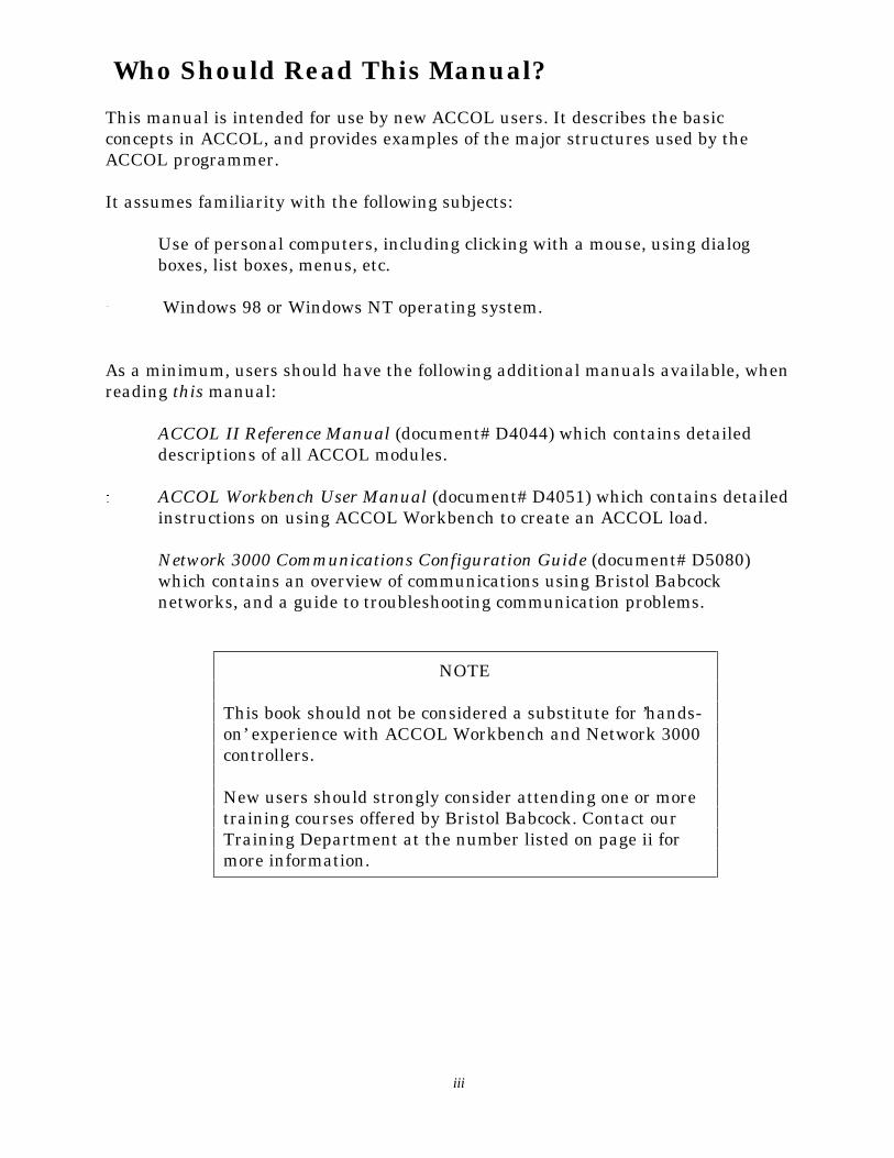
The reason signals are divided up into threeparts is that it allows a greater level oforganization for signals.
In the figure, at right, the Open BSIDataView utility is being used to search forall signals which share the commonextension ‘LEVEL’. The same type of searchcould be conducted based on base names orattributes.
Characteristics Common to All Signals
Every ACCOL signal has a set of characteristics associated with it. Depending upon thetype of signal (logical, logical alarm, analog, analog alarm, or string) the characteristicsmay vary, however, every signal, no matter which type, shares the characteristicsdescribed below:
Initial State or Value This is the starting value, as specified in the ACCOLsource file, which this signal will have when theACCOL load is initially downloaded into the Network3000 controller. The signal will maintain its initialstate or value, until such time as it is changed, eithermanually, through the intervention of an operator, orvia control instructions in the ACCOL load.
Manual Inhibit/Enable Flag The manual inhibit/enable flag is a status value,associated with the signal, which determines whetheror not an operator can change the value of the signal.The value of a manually enabled signal can be alteredby an operator. When a signal is manually inhibited,however, an operator cannot change the signal’svalue, without first manually enabling the signal.
Control Inhibit/Enable Flag The control inhibit/enable flag is a status value,associated with the signal, which determines whetheror not the execution of ACCOL control logic (modules,tasks, etc.) can change the value of the signal. Thevalue of a control enabled signal can be altered by

Chapter 2 - What Are Signals?
An Introduction to ACCOL Page 2-3
ACCOL control logic. When a signal is controlinhibited, however, control logic cannot change thesignal’s value. This flag is sometimes referred to as‘AUTO/MANUAL’.
Base name Text Every signal has a base name. If desired, a descriptivetext message may be associated with the base name.The full text of this message is only visible in thoseSCADA/HMI packages which are specificallyequipped to display it. The base name text for aparticular base name is shared by all signals with thesame base name.
For example, if the base name COMPRSR2 hasdescriptive text of ‘COMPRESSOR NUMBER 2’, andthe ACCOL source file contains two signals with abase name of COMPRSR2:
COMPRSR2.POWER.STAT andCOMPRSR2.RUN.TIME,
then both those signals will share the common basename descriptive text of ‘COMPRESSOR NUMBER 2’.
Base name text can be defined in the *BASENAMESsection of the ACCOL source file, -OR- it can bedefined via a separate string signal. (String signalswill be discussed later in this section.)
ACCOL supports six levels of security access (1 to 6), with 6 being the highest level. Eachlevel has, associated with it, a security code. Any operator using Open BSI Utilities, orcertain ACCOL Tools must sign-on with one of these security codes. Once signed on, theoperator is then allowed access to system functions which accept a security level lessthan or equal to his or her security level. For example, an operator with security level 4has access to functions requiring level 1 to 4, but is prohibited from accessing functionsrequiring security level 5 or 6.
Read Priority The Read Priority value specifies the minimumsecurity level an operator must sign on with, in orderto view (i.e. read the value of) this signal.
Write Priority The Write Priority value specifies the minimumsecurity level an operator must sign on with, in orderto change the value of (i.e. write to) this signal.

Chapter 2 - What Are Signals?
Page 2-4 An Introduction to ACCOL
Additional signal characteristics vary depending upon the signal type, and will bedescribed, below:
Logical Signals
Logical signals can only have two possible values: ON or OFF.2
Logical signals are therefore used for data which can only have two possible states. Forexample, if a valve is either OPENED or CLOSED, its value can be stored in a logicalsignal. Similarly, if a pump is either ON or OFF, a logical signal could be used to storeits value. Logical signals are also useful in the creation of Boolean logic expressions.
Logical signals have the following characteristics: (in addition to those described underCharacteristics Common to All Signal Types).
ON/OFF Text In certain on-line tools (in Open BSI, for example) the state of alogical signal is shown as ‘ON’ if the signal is ON, and ‘OFF’ ifthe signal is OFF. A signal’s ON/OFF text may be changed,however, to better represent the signal’s function. For example, itmay be desirable to edit this text in the source file so that the ONtext is ‘ACTIVE’, and the OFF text is ‘FAILED’. Both the ON textand OFF text may be up to six characters in length.
LOC/GLB Flag Certain HMI/SCADA packages will only collect data from signalswhich are alarms, or are specified as global signals ‘GLB’. Thesepackages will ignore signals specified as local ‘LOC’. This flag,therefore, allows the user to designate whether or not suchpackages should collect data from this signal.
RBE Flag Report by Exception (RBE) is a method of data collection, used bycertain HMI/SCADA packages, which will cause data fromsignals to be collected only if the signal value changes. Thisminimizes the amount of message traffic in the system. Bydefault, signals are NOT RBE signals.
Logical Alarm Signals
Logical Alarm Signals are similar to logical signals, except that when they change state,they generate an alarm message.3 These signals are used to store data which is more
2 The controller stores an OFF as the number ‘0’ and an ON as the number ‘1’.3 Alarm messages are immediately transmitted out of the controller’s slave port, to the next highest node in thenetwork, until they reach whatever device is used to notify the operator of the alarm (PC Workstation, printer, etc.)

Chapter 2 - What Are Signals?
An Introduction to ACCOL Page 2-5
critical to the operation of a process, for example, a logical alarm signal might be used toindicate that a pump or compressor has failed.
Logical alarm signals have the following characteristics: (in addition to those describedunder Characteristics Common to All Signal Types).
ON/OFF Text See description under Logical Signals.
RBE Flag See description under Logical Signals. NOTE: In general, alarmsignals should NOT be designated as RBE signals.4
Alarm Priority Alarm signals can also be further classified based on the severity ofthe alarm condition. This severity level is called the alarm priority.There are four possible priority levels, which will be discussed inascending level of importance. The choice of which signals shouldhave a given alarm priority is entirely at the discretion of theprogrammer.
Event - Signals specified as event alarms are used to indicatenormal, everyday occurrences.
Operator Guide - Signals specified as operator guide alarmsare used to indicate everyday occurrences as well, however,they are slightly more important than events.
Non-Critical - Signals specified as non-critical are used toindicate problems which, while not serious enough to causedamage to a plant or process, require corrective action by anoperator.
Critical -Signals specified as critical are used to indicatedangerous problems which require immediate operatorattention, and corrective action.
Alarm Type The type of an alarm specifies under what conditions the signalenters an alarm state. There are three possible choices:
Alarm ON - with this choice, an alarm message is generatedwhen the signal turns ON, and a ‘return to normal’ alarmmessage is generated when the signal turns OFF.
4 Alarms are always reported before RBE change reports, therefore, if a signal is collected both as an alarm, and as an
RBE change, there is a possibility that an older RBE message could arrive after an alarm message, thereby overwritingnewer data with older data. Because of this interaction of the two data collection methods, it is recommended that alarmsignals NOT be designated as RBE signals. For more information on Report by Exception, see the ACCOL II ReferenceManual (document# D4044).

Chapter 2 - What Are Signals?
Page 2-6 An Introduction to ACCOL
Alarm OFF - with this choice, an alarm message is generatedwhen the signal turns OFF, and a ‘return to normal’ alarmmessage is generated when the signal turns ON.
Change of State - with this choice, an alarm message isgenerated anytime the signal changes state from ON toOFF, or from OFF to ON.
Alarm Inhibit/ Enable Flag The alarm inhibit/enable flag is a status value, associated with the
signal, which determines whether or not alarm messages will betransmitted. Setting this flag to ‘Enable’ allows transmission of alarmmessages to occur. Setting this flag to ‘Inhibit’ prevents thetransmission of alarm messages from this signal.
Analog Signals
Analog signals are used to store numerical data. Examples of such data might include,temperature readings, pressure readings, or flow totals. The numerical data is stored as4-byte floating point numbers in IEEE format.5 The non-zero numerical value of ananalog signal can range from:
+1.175494 x 10-38 to +3.402823 x 1038
Analog signals have the following characteristics: (in addition to those described underCharacteristics Common to All Signal Types).
LOC/GLB Flag Certain HMI/SCADA packages will only collect data from signalswhich are alarms, or are specified as global signals ‘GLB’. Thesepackages will ignore signals specified as local ‘LOC’. This flag,therefore, allows the user to designate whether or not suchpackages should collect data from this signal.
RBE Flag Report by Exception (RBE) is a method of data collection, used bycertain HMI/SCADA packages, which will cause data fromsignals to be collected only if the signal value changes. Thisminimizes the amount of message traffic in the system. Bydefault, signals are NOT RBE signals.
RBE Deadband Analog signals which have been designated as RBE signals may
5 See Appendix B for more information on working with floating point numbers.

Chapter 2 - What Are Signals?
An Introduction to ACCOL Page 2-7
have an associated deadband.6 The deadband represents arange, above and below the last reported value of the signal, inwhich changes to the signal will not be reported. If the signalgoes out of this range, for a period of time long enough to bedetected by an RBE scan, then an exception has occurred, andthe change will be reported.
Units Text Units text specifies the engineering units for this particularsignal. Up to six characters of units text may be defined. Typicalexamples of units text include: ‘HOURS’, ‘FEET’, ‘INCHES’, and‘PSIG’.
Analog Alarm Signals
Analog Alarm Signals are similar to analog signals, except that when the signal valueexceeds certain pre-defined alarm limits, an alarm message is generated. These signalsare used to store data which is more critical to the operation of a process, for example, ananalog alarm signal might be used for temperature or pressure readings of criticalsystem components.
Analog alarm signals have the following characteristics: (in addition to those describedunder Characteristics Common to All Signal Types).
Units Text See description under Analog Signals.
RBE Flag See description under Analog Signals. NOTE: In general, alarmsignals should NOT be designated as RBE signals.7
RBE Deadband See description under Analog Signals.
Alarm Enable/Inhibit Flag See description under Logical Alarm Signals.
Alarm Limits andDeadbands An analog alarm signal generates an alarm message when the value
6 The concept of deadbands is explained in more detail in the discussion of alarm limits for analog alarm signals, laterin this section.7 Alarms are always reported before RBE change reports, therefore, if a signal is collected both as an alarm, and as anRBE change, there is a possibility that an older RBE message could arrive after an alarm message, thereby overwritingnewer data with older data. Because of this interaction of the two data collection methods, it is recommended that alarmsignals NOT be designated as RBE signals. For more information on Report by Exception, see the ACCOL II ReferenceManual (document# D4044).

Chapter 2 - What Are Signals?
Page 2-8 An Introduction to ACCOL
of the signal exceeds a pre-defined alarm limit. Up to four alarmlimits may be defined; every analog alarm signal must have at leastone limit defined, or else the signal will never generate an alarmmessage.
The four alarm limits are the high alarm limit, the high-high alarmlimit, the low alarm limit, and the low-low alarm limit. Each of thesealarm limits can be specified in the ACCOL source file as either aconstant, or as an ACCOL signal. In general, specifying an ACCOLsignal provides more flexibility, because it allows the limit to bechanged dynamically, either by the operator, or through logic in theACCOL load.
In addition to the alarm limits, there are two deadbands: the lowdeadband and the high deadband. A deadband represents a rangejust above or below the alarm limit (depending upon whether it’s ahigh or low alarm) in which the signal remains in an alarm state,despite the fact that its value no longer exceeds the alarm limit.Without the deadband, if the signal’s value rapidly fluctuates aboveand below the alarm limit, the signal would constantly be going inand out of an alarm state, thereby flooding the system with alarmand return to normal messages. A properly defined deadband helpsprevent this situation.
Deadbands can be defined in the ACCOL source file as eitherconstants, or as signals.
When the value of an analog alarm signal passes one of its alarmlimits, an alarm message is generated.8
In the case of a high, or high-high alarm, the alarm condition doesnot clear (i.e. generate a ‘return to normal’ alarm message) until thevalue of the signal goes below the alarm limit, minus the value of thehigh deadband.
In the case of a low, or low-low alarm, the alarm condition does notclear until the value of the signal rises above the alarm limit, plusthe value of the low deadband.
An example of alarm limits and deadbands is illustrated in the figure on the oppositepage. In this example, we are showing a plot of the value of a signal measuring Celsius 8 In order for alarm limits to function properly, the high-high limit must be a higher number than the high limit, the highlimit must be a higher number than the low limit, and the low-low limit must be a lower number than the low limit. Inaddition, deadbands should always be entered as positive numbers.

Chapter 2 - What Are Signals?
An Introduction to ACCOL Page 2-9
temperature, as it fluctuates over time. The four alarm limits and two deadbands areshown in the figure. The normal range for this signal is temperatures between 400 C and700 C. Temperatures outside of this range are considered to be alarm conditions.
Starting from the left of the graph, the value of the signal increases until it reaches 700
C, the high alarm limit (see Item 1). At this point a high alarm message is generated,and the signal is considered to be in a ‘high alarm’ state.
The value of the signal continues to increase. When it passes the high-high alarm limitof 900 C a ‘high-high’ alarm message is generated (see Item 2). At this point, the signal isconsidered to be in a high-high alarm state.
The value of the signal then starts to decrease. Although the value passes below 900C, itis still considered to be in a ‘high-high’ alarm state because there is a 100 high deadbandin effect (deadbands are shown as shaded areas on the graph.) When the signal valuefalls lower than 800 C point (900 C high alarm limit minus the high deadband of 100 C)the signal is no longer in a ‘high-high’ alarm state (See Item 3). It is still however in a‘high’ alarm state.
As the value of the signal decreases below 700 C, it remains in a ‘high’ alarm state untilits value falls below 600 C (700 C alarm limit, minus a 100 C high deadband). (See Item 4).At this point, the signal is in its normal range, and a ‘return-to-normal’ alarm message issent.
Then, however, the value of the signal continues to drop. When it reaches 400 C, a ‘LowAlarm’ message is generated (See Item 5).
The signal remains in a ‘Low Alarm’ state until the signal value drops to 200 C. (See Item6). This causes a ‘Low Low Alarm’ message to be generated.
The signal remains in a ‘Low-Low Alarm’state until the signal rises above 300 C, (200
C low-low alarm limit plus low deadband of100 C). (See Item 7). The signal is still in a‘Low Alarm’ state, however.
Once the signal rises above 500 C (400 C lowalarm limit + low deadband of 100 C), it hasleft the low-alarm state, and a ‘return tonormal’ alarm message is sent (See Item 8).
As long as the signal remains in thenormal range (between 40 and 700 C), nomore alarm messages will be generated.
Chapter 2 - What Are Signals?
Page 2-10 An Introduction to ACCOL
String Signals
The last type of signal is the string signal. The value of a string signal is a messageconsisting of up to 64 characters of ASCII text. These messages are called characterstrings, because they are a bunch of characters tied together. For example, a stringsignal called STATION.TAG.NAME may have a value of ‘ELM STREET COMPRESSORSTATION’.
String signals are typically used to provide readable status messages. Some SCADA/HMIpackages are also equipped to display these messages.
A less common use of string signals is to hold the base name descriptive text for anothersignal. Normally a signal’s base name descriptive text is defined in the source file as aconstant; if a string signal name is entered instead, the base name descriptive text canbe changed on-line.
The Calculator Module (which will be discussed in the section Modules) also supportscertain functions for string manipulation including checking the length of a string,comparing the value of two strings, and concatenating (putting together) two strings.
String signals have the following characteristics: (in addition to those described underCharacteristics Common to All Signal Types).
String Length The length (number of characters) of the message (including spaces).No string may be longer than 64 characters.

Chapter 2 - What Are Signals?
An Introduction to ACCOL Page 2-11
System Signals
Every ACCOL load contains a series of system signals System signals are createdautomatically by the system, and are distinguished from other ACCOL signals by thepresence of a pound sign ‘#’ at the beginning of the base name.
For example, the system signal #TIME.000. indicates the current Julian date and time.The system signal #NODEADR.. indicates the local address of the controller (as set viahardware or software switches).
There are numerous other system signals which are used for ‘housekeeping’ such asholding task characteristics, and error information.
The ACCOL programmer cannot create or delete system signals, but can make use ofthem on module terminals, or in equations.
For more information on system signals, see the ACCOL II Reference Manual(document# D4044).
How Are Signals Created?
All signals must be defined in the‘*SIGNALS’ section of the ACCOLsource file (.ACC). Base namedescriptive text for the signals isdefined in the ‘*BASENAMES’section of the file.
Instructions for defining signals andbase name text are included in theACCOL Workbench User Manual(document# D4051).
Chapter 2 - What Are Signals?
Page 2-12 An Introduction to ACCOL
How Does the Operator View Signal Values?
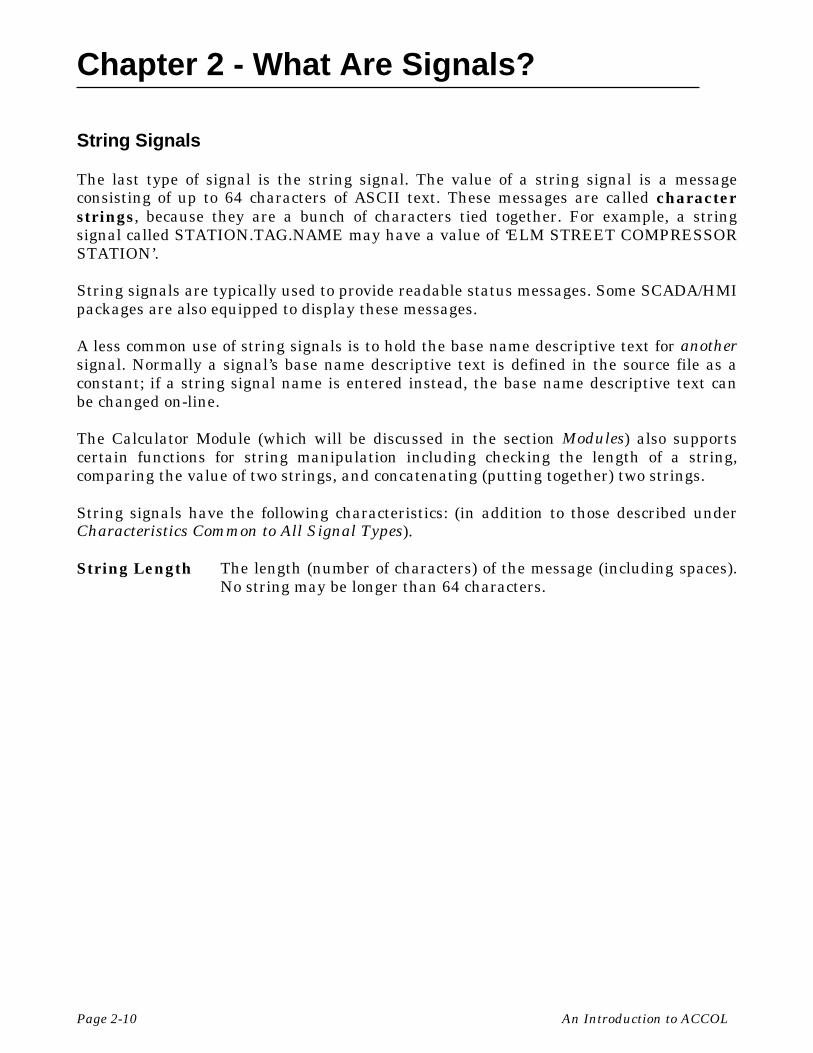
There are several different ways to view signal data in a running Network 3000 seriescontroller.
" While running the Open BSI DataView utility, users can call up signals by a signalsearch, by the full signal name, or through lists. Signal values may also be changedvia dialog boxes. See the Open BSI Utilities Manual (document# D5081) for details.
" Signal data can be exported to DDE compliant applications such as spreadsheets andword processors using the Open BSI DDE Server program. See the Open BSICollection/Export Utilities Manual (document# D5083) for details.
" Users with Bristol Babcock’s Universal Operator Interface (UOI) software canconfigure text-based menus and logs to include signal data. See the UOIConfiguration Manual (document# D5074) for details.
" If you are using an HMI/SCADA software package such as OpenEnterprise,Enterprise Server, Intellution® FIX®, Iconics Genesis, etc., signal values may be usedto drive the color and appearance of graphic symbols on screen displays, trend lines,etc. See the documentation accompanying the HMI/SCADA software for details.
Chapter 3 - What Are Modules?
An Introduction to ACCOL Page 3-1
What Are Modules?
Modules are pre-programmed structures which are used to perform mathematical,communication, and process control functions.1 Within ACCOL Workbench, theprogrammer chooses from a library of modules, and inserts the selected modules into oneor more ACCOL tasks in the source file.2,3
Each module has a series of terminals which represent its inputs and outputs. Theprogrammer ‘wires’ these terminals in software, by typing an ACCOL signal name nextto the terminal. By placing the same signal name on terminals of different modules, theprogrammer establishes a connection for data flow between the modules. In this way,data flows from an output terminal of one module, to an input terminal of anothermodule, and so on.4
How Do Modules Execute?
When a module executes, it reads its input terminals, performs any necessarycalculations, and then updates its output terminals.
Except for certain special modules in Task 0 (discussed later in this manual) modules doNOT execute unless the line of the task on which they are defined executes, thereforethe output terminals of a module do NOT change at any time except when the module isexecuting.
What Kinds of Modules Are Available?
There are over 80 different ACCOL modules. We will discuss a few broad categories ofavailable modules here. A full description of each module is included in the ACCOL IIReference Manual (document# D4044).
1 If you are familiar with other programming languages, you can think of a module as a sub-routine, or procedure.2 The pre-programming instructions for each module reside in firmware, a special kind of encoded software that residesin the remote process controller. When you install new versions of ACCOL Tools software, which include new modules,you may also need to install an upgrade to the controller firmware, in order to use the new modules or features. For somecontroller models, the firmware is referred to as the PROM set, because it resides in Erasable Programmable Read onlyMemory (EPROM) chips. In other controllers, the firmware is installed into a FLASH memory area. See the hardwaremanual of your controller for more information.3 The method for inserting modules into a task will be discussed in greater detail later.4 The terminals of a module are only updated with data when the module executes.

Chapter 3 - What Are Modules?
Page 3-2 An Introduction to ACCOL
Natural Gas Modules
There are several modules availablewhich implement natural gasindustry calculations, includingthose described in American GasAssociation reports. Among thesemodules are AGA3ITER, AGA5,AGA7, AGA8GROSS, AGA8DETAIL,FPV and ISO5167.
Input/Output (I/O) Modules
Most every ACCOL source fileincludes some I/O modules, sincethese modules are necessary to sendand receive data through thecontroller’s process I/O boards. Themost commonly used include theanalog input (ANIN), analog output(ANOUT), digital input (DIGIN) anddigital output (DIGOUT).
Mathematical Modules
These modules implement a variety ofdifferent arithmetic and logicalfunctions. Among those available arethe AVERAGER, COMPARATOR,INTEGRATOR, DIFFERENTIATOR,TOT/TRND, MUX, and DEMUXmodules.
10 * AGA8DETAILENABLE ;LOGICAL_SIGNALPRIORITY ;ANALOG_SIGNAL_OR_VALUEFLOW_TEMP ;ANALOG_SIGNAL_OR_VALUESTAT_PRESS ;ANALOG_SIGNAL_OR_VALUEBASE_TEMP ;ANALOG_SIGNAL_OR_VALUEBASE_PRESS ;ANALOG_SIGNAL_OR_VALUELIST ;ANALOG_SIGNAL_OR_VALUEARRAY ;ANALOG_SIGNAL_OR_VALUECOLUMN ;ANALOG_SIGNAL_OR_VALUEERROR ;ANALOG_SIGNALSTATUS ;ANALOG_SIGNALZ_FLOWING ;ANALOG_SIGNALZ_BASE ;ANALOG_SIGNALFPV ;ANALOG_SIGNAL
20 * ANOUTDEVICE DEVICE_IDINITIAL CHANNELOUTPUT 1 ;ANALOG_SIGNAL_OR_VALUEZERO 1 ;ANALOG_SIGNAL_OR_VALUESPAN 1 ;ANALOG_SIGNAL_OR_VALUETRACK 1 ;LOGICAL_SIGNALRESET 1 ;ANALOG_SIGNAL
30 * INTEGRATORINPUT ;ANALOG_SIGNAL_OR_VALUERESET ;LOGICAL_SIGNALZERO ;ANALOG_SIGNAL_OR_VALUESPAN ;ANALOG_SIGNAL_OR_VALUEOUTPUT ;ANALOG_SIGNAL

Chapter 3 - What Are Modules?
An Introduction to ACCOL Page 3-3
Communication Modules
These modules support data transmissionthrough the controller’s communicationports. Among the most commonly usedmodules are MASTER, SLAVE,EMASTER, LOGGER, CUSTOM,IP_CLIENT, and IP_SERVER.
Process Control Modules
These modules implement algorithmswhich are useful for process controlapplications including PID loop control(PID3TERM), LEAD/LAG, SCHEDULER,SEQUENCER, and STEPPER.
Calculator Module
One module which deserves special mention is the CALCULATOR module. If you areunable to find a module which suits your needs, you may often be able to create theneeded module yourself by entering statements in a Calculator Module. This modulesupports a wide range of arithmetic operators (add, subtract, multiply, divide, squareroot, SIN, COSINE), logical operators (IF, ELSE, AND, INCL OR, EXCL OR), and otheroperators related specifically to signals, and strings.
How Are Modules Placed in the ACCOL Source File?
Modules are inserted inside ACCOL Tasks in the ACCOL source file. ACCOL Tasks arediscussed in the next section. For information about inserting modules in them, see theACCOL Workbench User Manual (document# D4051).
40 * MASTERREMOTE ;ANALOG_SIGNAL_OR_VALUEPOINT ;ANALOG_SIGNAL_OR_VALUEMODE ;ANALOG_SIGNAL_OR_VALUEINTYPE ;ANALOG_SIGNAL_OR_VALUEOUTTYPE ;ANALOG_SIGNAL_OR_VALUEINDEX ;ANALOG_SIGNAL_OR_VALUEINLIST ;ANALOG_SIGNAL_OR_VALUEOUTLIST ;ANALOG_SIGNAL_OR_VALUESTATUS_1 ;ANALOG/LOGICAL_SIGNALSTATUS_2 ;ANALOG_SIGNAL
50 * PID3TERM INPUT ;ANALOG_SIGNAL_OR_VALUE SETPOINT ;ANALOG_SIGNAL_OR_VALUE DEADBAND ;ANALOG_SIGNAL_OR_VALUE PROPORTION ;ANALOG_SIGNAL_OR_VALUE INTEGRAL ;ANALOG_SIGNAL_OR_VALUE DERIVATIVE ;ANALOG_SIGNAL_OR_VALUE RESET ;ANALOG_SIGNAL_OR_VALUE TRACK ;LOGICAL_SIGNAL OUTPUT ;ANALOG_SIGNAL ERROR ;ANALOG_SIGNAL
60 * CALCULATOR 10 :IF((TANK7.WATER.LEVL>12)&(DRAIN.ENABLE.ON)) 20 OPEN.DRAIN.VALV=#ON 30 :ENDIF

BLANK PAGE

Chapter 4 - What Are ACCOL Tasks?
An Introduction to ACCOL Page 4-1
What Are ACCOL Tasks?
An ACCOL task is a series of modules and control statements which executesequentially as a functional block. Task execution occurs at a user-specified rate andpriority.
ACCOL tasks provide a way to organize the ACCOL source file into smaller, moremanageable pieces. For example, at a compressor station for a natural gas pipeline, thereare critical flow, temperature and pressure calculations, as well as I/O operations; thesemight fit well in one high priority task. Less critical calculations, such as daily flowtotals, and averages, might be separated out into a lower priority task. Communicationthrough master modules may be handled through yet another task.
Each ACCOL task is assigned a unique number. ACCOL supports over 100 tasks,however, most users find that using a few tasks is most efficient.
Communication Between Tasks
Data is transferred from one task to another in the same way that data moves frommodule to module, via signals.
To send a value of an output terminal in one task to the value of an input terminal inanother task, simply ‘wire’ the same signal name on both terminals.
Other ACCOL structures, such as data arrays, signal lists, etc., are also shared amongall tasks.
Task Rate
The task rate specifies how often the controller will initiate execution of this task.1
The task rate is specified in units of seconds, and is defined in the ACCOL source file,and may be modified on-line through the #RATE.nnn system signal (where nnn specifiesthe task number). The task rate can be as fast as 0.02 seconds (20 milliseconds), or asslow as 5400 seconds (90 minutes). Setting the task rate to 0 stops execution of the task.
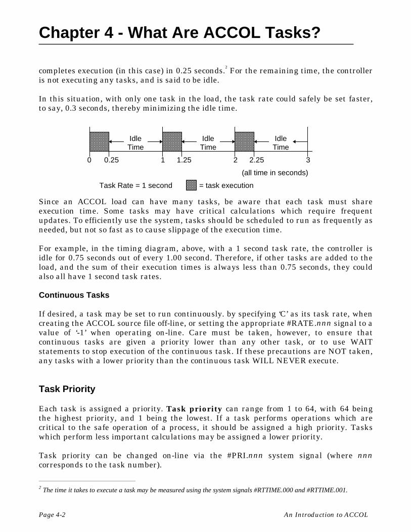
In the timing diagram, on the next page, an ACCOL load with a single task has a taskrate set at 1 second. Each second, the task is scheduled to start executing, and it
1 If the time it takes to execute the task is longer than the rate specified, the next execution of the task will NOT bestarted on schedule. It must wait until the previous execution of the task has completed. This delay is called slippage, andis recorded as a slip count error in the system signal #RCNT.nnn where nnn is the task number.
Chapter 4 - What Are ACCOL Tasks?
Page 4-2 An Introduction to ACCOL
completes execution (in this case) in 0.25 seconds.2 For the remaining time, the controlleris not executing any tasks, and is said to be idle.
In this situation, with only one task in the load, the task rate could safely be set faster,to say, 0.3 seconds, thereby minimizing the idle time.
Since an ACCOL load can have many tasks, be aware that each task must shareexecution time. Some tasks may have critical calculations which require frequentupdates. To efficiently use the system, tasks should be scheduled to run as frequently asneeded, but not so fast as to cause slippage of the execution time.
For example, in the timing diagram, above, with a 1 second task rate, the controller isidle for 0.75 seconds out of every 1.00 second. Therefore, if other tasks are added to theload, and the sum of their execution times is always less than 0.75 seconds, they couldalso all have 1 second task rates.
Continuous Tasks
If desired, a task may be set to run continuously. by specifying ‘C’ as its task rate, whencreating the ACCOL source file off-line, or setting the appropriate #RATE.nnn signal to avalue of ‘-1’ when operating on-line. Care must be taken, however, to ensure thatcontinuous tasks are given a priority lower than any other task, or to use WAITstatements to stop execution of the continuous task. If these precautions are NOT taken,any tasks with a lower priority than the continuous task WILL NEVER execute.
Task Priority
Each task is assigned a priority. Task priority can range from 1 to 64, with 64 beingthe highest priority, and 1 being the lowest. If a task performs operations which arecritical to the safe operation of a process, it should be assigned a high priority. Taskswhich perform less important calculations may be assigned a lower priority.
Task priority can be changed on-line via the #PRI.nnn system signal (where nnncorresponds to the task number).
2 The time it takes to execute a task may be measured using the system signals #RTTIME.000 and #RTTIME.001.
Idle Idle IdleTime Time Time
0 0.25 1 1.25 2 2.25 3
(all time in seconds)
Task Rate = 1 second = task execution

Chapter 4 - What Are ACCOL Tasks?
An Introduction to ACCOL Page 4-3
ACCOL uses a technique called pre-emptive multi-tasking. This means that multipletasks execute concurrently, however, higher priority tasks are given priority over lowerpriority ones.
If two or more tasks are scheduled to execute at the same moment, the one with thehigher priority will be executed first. As time becomes available, the task with the nexthighest priority will be executed, and so on. If two tasks share the same priority, theywill be executed on a rotating basis.
If a high priority task is required to run, and a lower priority task has not finishedexecution, execution of the lower priority task will be suspended to allow the higherpriority task to run. The lower priority task can only resume execution when higherpriority tasks have finished.
If you have a continuous task (described earlier), it must have the lowest priority relativeto all other tasks, or it must be stopped by WAIT statements (WAIT FOR, WAIT DELAY,etc.) or else NO OTHER TASKS WILL EXECUTE.
System Tasks
Another consideration when setting task priority is to avoid conflicts with system tasks.A system task is a task in the system firmware, which performs some function during theexecution of the ACCOL load. A table of system task priorities is included in the ‘Task’section of the ACCOL II Reference Manual (document# D4044). Never assign an ACCOLtask a priority that is higher than one of the system tasks which will be used in yourACCOL load, or the system task may be unable to run when it is needed.
Redundancy Frequency
If you are using a redundant pair of Network 3000 controllers, then a redundancyfrequency of 1 should be specified.3 If you are NOT using redundant controllers, aredundancy frequency of 0 should be specified.
Task 0 - The Special Task
Every ACCOL load has a task numbered 0. Task 0 is a special task which does notexecute at a specified rate. Instead, it is used to hold certain modules which do NOT
3 In general, a redundancy frequency of 1 should be specified for redundant units. For additional information onredundancy frequency, see the ‘Redundancy Concepts’ section of the ACCOL II Reference Manual (document#D4044).

Chapter 4 - What Are ACCOL Tasks?
Page 4-4 An Introduction to ACCOL
execute on their own, except when activated by other ACCOL modules. The following arenon-executing modules, which are appropriate for use in Task 0:
AUDITEASTATUSEAUDITRBEREDUNDANCYRIOSTATSSLAVE
All other modules should be placed in tasks which execute at a specified rate.
Task Control Statements
Normally, the modules in a task execute in sequential order. Task Control Statementscan be inserted in the task to modify the flow of execution.
Modules can be conditionally skipped using IF/ENDIF/ELSE/ELSEIF statements.Modules can be repeatedly executed using FOR/ENDFOR statements.
The entire task can wait for a particular event to occur, or time to elapse, using WAITstatements.
The task can even suspend its execution with a SUSPEND statement. The task can thenonly be re-started by a RESUME statement in a different task.
In the simple example task, shown, below, only one of the two single-line calculatormodules will execute; which one is chosen depends upon the hour of the day determinedin the IF statement:
The following is a list of sections in the ACCOL II Reference Manual (document# D4044)which contain details on control statements.
ABORTBREAKCONTROL STATEMENTS
**TASK 2 RATE: 0.500000 PRI: 1 REDUN: 010 * C SIMPLE TASK TO TURN ON LIGHTS IN A ROOM20 * C BETWEEN 4:00 PM AND 6:00 AM30 * IF ((#TIME.005.>16)|(#TIME.005.<6))40 * CALCULATOR ROOM.LIGHT.=#ON..50 * ELSE60 * CALCULATOR ROOM.LIGHT.=#OFF..70 * ENDIF
Chapter 4 - What Are ACCOL Tasks?
An Introduction to ACCOL Page 4-5
IF/ENDIF/ELSE/ELSEIFFOR/ENDFORGOTORESUMESUSPENDWAIT DELAYWAIT DI/RWAIT DIWAIT FORWAIT TIME
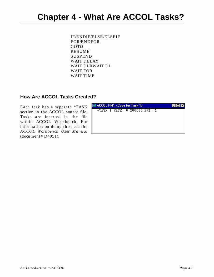
How Are ACCOL Tasks Created?
Each task has a separate *TASKsection in the ACCOL source file.Tasks are inserted in the filewithin ACCOL Workbench. Forinformation on doing this, see theACCOL Workbench User Manual(document# D4051).

BLANK PAGE
Chapter 5 - What Are Data Arrays?
An Introduction to ACCOL Page 5-1
What Are Data Arrays?
Data arrays are essentially tables. They are organized in rows and columns, and eacharray element (cell) can hold a single piece of data.
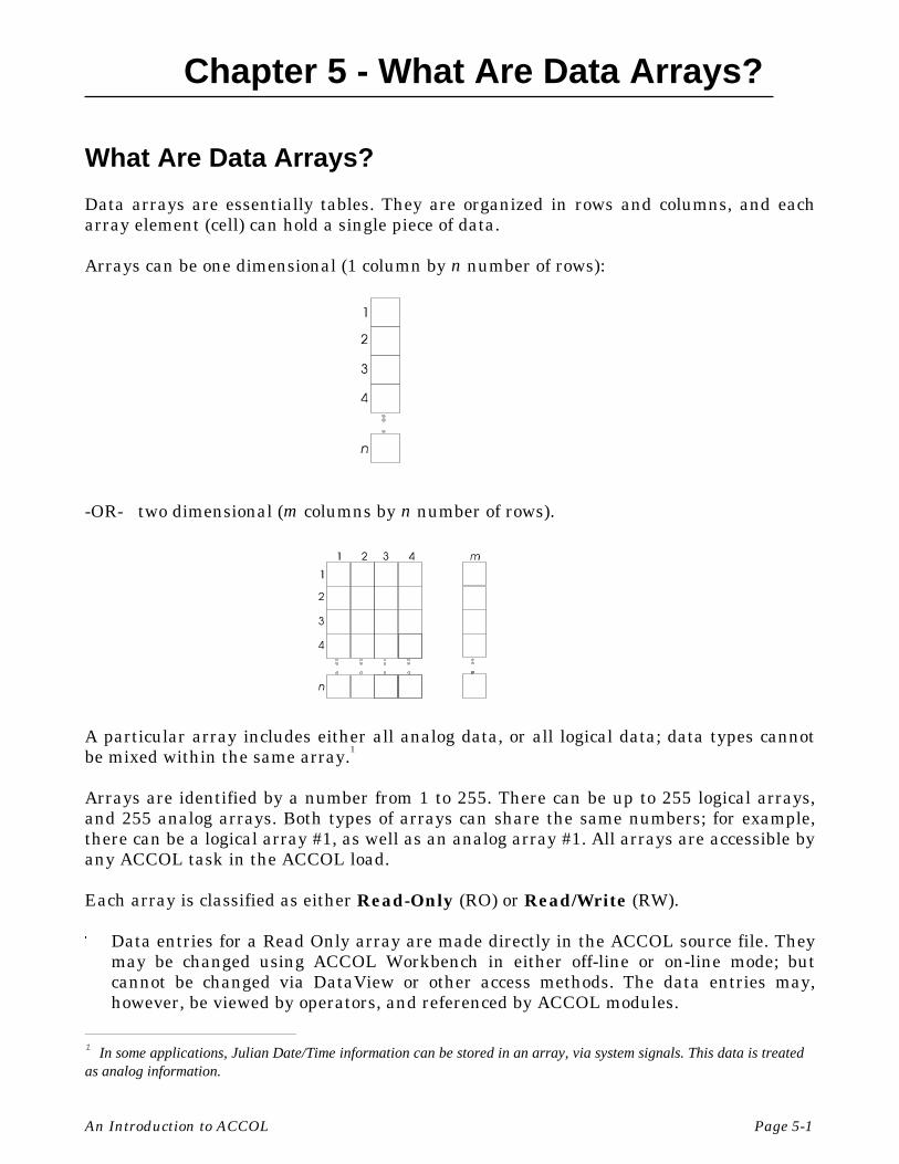
Arrays can be one dimensional (1 column by n number of rows):
-OR- two dimensional (m columns by n number of rows).
A particular array includes either all analog data, or all logical data; data types cannotbe mixed within the same array.1
Arrays are identified by a number from 1 to 255. There can be up to 255 logical arrays,and 255 analog arrays. Both types of arrays can share the same numbers; for example,there can be a logical array #1, as well as an analog array #1. All arrays are accessible byany ACCOL task in the ACCOL load.
Each array is classified as either Read-Only (RO) or Read/Write (RW).
" Data entries for a Read Only array are made directly in the ACCOL source file. Theymay be changed using ACCOL Workbench in either off-line or on-line mode; butcannot be changed via DataView or other access methods. The data entries may,however, be viewed by operators, and referenced by ACCOL modules.
1 In some applications, Julian Date/Time information can be stored in an array, via system signals. This data is treatedas analog information.
Chapter 5 - What Are Data Arrays?
Page 5-2 An Introduction to ACCOL
" Read/Write Array entries, conversely, can only be specified on-line, either by anoperator entering values, or by the execution of ACCOL logic.
Modules Which Are Commonly Used With Arrays
Although many ACCOL modules use arrays, some are specifically designed for arrayaccess or array data manipulation.
" Storage Module
This module allows data to be read from a data array and stored in a signal list orread from a signal list and stored in a data array.
" Function Module
This module can use an array as a look-up table. The first row and first column of thearray must each include values in ascending order. These values will be used asindices, to look up values from among the remaining array elements. Interpolationcan be performed by the module if row and column indices are not exact.
" Stepper Module
This module is used in applications which can be divided up into a specific set ofsteps, and where each step requires a certain set of signal outputs. Each row of thearray represents required signal outputs for a step in the sequence.
" Encode Module
Function 8 of the Encode Module allows array rows (or columns) to be shifted withinthe array, in a specified direction. This simplifies array manipulation in a variety ofapplications.
" Calculator Module
Individual array elements (cells) can be read using Calculator equations. In addition,array elements in read/write arrays can be changed using Calculator equations. Seethe ‘Calculator’ section of the ACCOL II Reference Manual (document# D4044) fordetails.
All of these modules are discussed in detail in the ACCOL II Reference Manual(document# D4044).

Chapter 5 - What Are Data Arrays?
An Introduction to ACCOL Page 5-3
Typical Applications For Read Only Arrays
Because read only arrays cannot be changed, they are typically used to store referenceinformation, which the ACCOL logic will refer to later.
Steam Table
One possible application for a read only analog array is to store a steam table. In thefigure, shown below, a portion of a steam table is shown in an array format. The firstcolumn represents absolute pressure, and the top-most row represents a range oftemperatures. The remaining array elements represent enthalpy in units of BTUs perpound of steam.
0 360 380 400 420 45080 1211.0 1221.5 1231.5 1240.3 1255.785 1210.0 1220.5 1230.7 1239.7 1255.190 1209.0 1219.8 1230.0 1239.1 1254.5
A user could configure a Function Module to access the array. The Function Module usesthe values in row 1 and column 1 to locate appropriate array cells. For example, if theFunction module ROW terminal is 85, and the Function module COLUMN terminal is400, the Function module OUTPUT terminal will have a value of 1230.7. If the ROW andCOLUMN values fall between the values in the rows and columns, an interpolation willbe performed. For example, if the ROW terminal is 85, and the column terminal is 390, avalue halfway between the 380 COLUMN value of 1220.5 and the 400 COLUMN valueof 1230.7 will be calculated, resulting in an OUTPUT value of 1225.6.
For details on how to configure the Function Module, see the ACCOL II ReferenceManual (document# D4044).
Output Statuses For A Water Filter Backwash Sequence
One possible use of a logical read only array would be to hold the status values to beused for each step of a water filter backwash sequence in a water treatment plant.
For example, let’s say that a simple water treatment plant has three valves and threepumps which are used as part of a backwash sequence. The details of the sequence arepresented in the table on the next page. (Note: This sequence has been greatly simplifiedfor purposes of explaining the Stepper Module; the details of an actual backwashsequence are longer and more complex.)

Chapter 5 - What Are Data Arrays?
Page 5-4 An Introduction to ACCOL
Device: InfluentValve
InfluentPump
WashPump
DrainValve
EffluentValve
EffluentPump
Step 1 CLOSED OFF OFF CLOSED OPENED ONStep 2 CLOSED OFF OFF CLOSED CLOSED OFFStep 3 CLOSED OFF OFF OPENED CLOSED OFFStep 4 CLOSED OFF ON OPENED CLOSED OFFStep 5 CLOSED OFF OFF CLOSED CLOSED OFFStep 6 OPENED ON OFF CLOSED OPENED ON
The details of this sequence can be stored in a logical array of ON/OFF status values.The ACCOL programmer creates an array, as shown below, where each columncorresponds to a specific device (pump, valve, etc.,) and each row represents a specificstep of the backwash sequence. The programmer enters in each element of the array a 1for ON (open, start, etc.) or a 0 for OFF (close, stop, etc.).
0 0 0 0 1 10 0 0 0 0 00 0 0 1 0 00 0 1 1 0 00 0 0 0 0 01 1 0 0 1 1
The Stepper Module executes the rows in an order specified by the ACCOL programmer,for a specified duration. When a particular step (row) is activated, the proper statuscommands for that step are retrieved from the array, and output to logical signals inorder to drive the action of the valves, pumps, etc.
For details on how to configure the Stepper Module, see the ACCOL II Reference Manual(document# D4044).

Chapter 5 - What Are Data Arrays?
An Introduction to ACCOL Page 5-5
Typical Applications for Read/Write Arrays
Read/Write arrays are used for data which changes during execution, either via ACCOLlogic, or via operator intervention.
Storing Hourly Totals or Averages
One common usage would be for storing hourly flow, temperature, and pressure totals fora natural gas pipeline compressor station.
For this example application, the programmer hascreated three analog signals namedCOMPRSR5.PRESUR., COMPRSR5.TEMP., andCOMPRSR5.FLOW. which contain the currentpressure, temperature, and flow totals, respectively,for this compressor station.
Each of these signals is ‘wired’ to one of the INPUTterminals of the Storage Module. Every hour, thevalue of these signals will be copied, using theStorage Module, into the next available row of a 3column by 24 row read/write analog array. Forinformation on using the Storage Module, see theACCOL II Reference Manual (document# D4044).
Detecting Task Execution Errors
Sometimes an ACCOL programmerconfigures structures which result in illegaloperations. For example, entering acalculator equation which attempts to dividea value by zero. Such errors, are detected bythe firmware. In order for the user to viewthe error code, however, an analog read/write error array must be defined.
The number of the array must be specifiedusing the #ERARRAY.. system signal. Thearray itself must have four columns, and asmany rows as the highest numbered task inthe system. Each row represents an ACCOLTask, the columns associated with that row

Chapter 5 - What Are Data Arrays?
Page 5-6 An Introduction to ACCOL
contain data about which type of module or equation in the task caused the error, andthe error code. Note that if there are multiple errors, only the most recently detectederror will be displayed for each task.
For a full description of how to configure the error array, as well as a description of whateach error code means, see the #ERARRAY.. portion of the ‘System Signals’ section in theACCOL II Reference Manual (document# D4044). ACCOL Workbench, when operating inon-line mode, can also display the meaning of the error code.
Node Array For Tuning On/Off Polling to Selected Network 3000 Nodes in a BSAPNetwork
One important use for a Read/Write Logical Array is to set up a node array for turningON/OFF communication requests to slave nodes of this controller.
The number of the logical array tobe used is specified by the systemsignal #NDARRAY..
The ACCOL programmer creates anumber of rows equal to the highestslave address. For example, if theACCOL program we are creating isfor a controller which is master to 4slave controllers, a four row by onecolumn logical read/write arrayshould be created.
Normally, the operator or ACCOL logic should leave each element set to ON, so thatcommunication with slave nodes can occur. If, for whatever reason, one or more slavenodes are taken out of service (failure, maintenance, repairs, communication problems)then polling for them should be turned off using the #NDARRAY. This preventsunnecessary communication attempts by the master to a non-existent node.
In the figure, shown above, the third slave node has been struck bylightning and so has failed. The master controller (which contains thenode array) will continue attempts to communicate with it, until, the thirdelement in the #NDARRAY (corresponding to address 3) is changed fromON to OFF by the operator, as shown at right.
For a full description of how to configure the node array, see the #NDARRAY portion ofthe ‘System Signals’ section in the ACCOL II Reference Manual (document# D4044).
Address 1 Address 2 Address 3 Address 4
#NDARRAY 1
1
1
1
Address 1 Address 2 Address 3 Address 4
Chapter 5 - What Are Data Arrays?
An Introduction to ACCOL Page 5-7
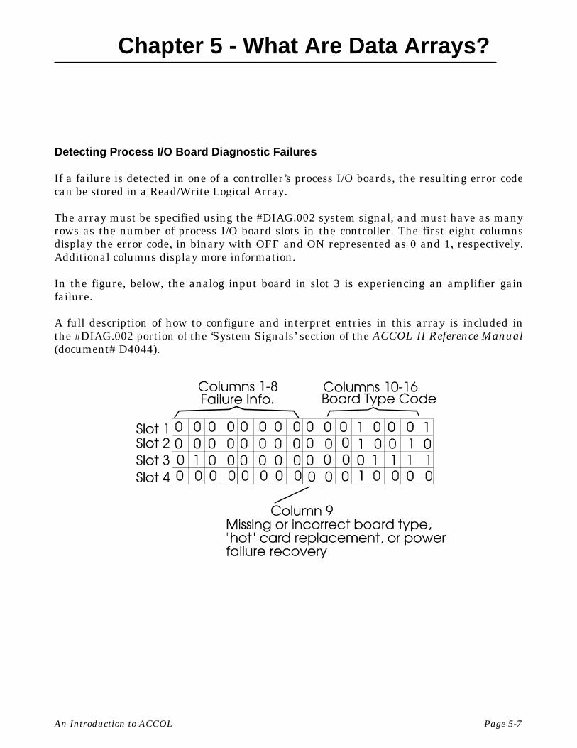
Detecting Process I/O Board Diagnostic Failures
If a failure is detected in one of a controller’s process I/O boards, the resulting error codecan be stored in a Read/Write Logical Array.
The array must be specified using the #DIAG.002 system signal, and must have as manyrows as the number of process I/O board slots in the controller. The first eight columnsdisplay the error code, in binary with OFF and ON represented as 0 and 1, respectively.Additional columns display more information.
In the figure, below, the analog input board in slot 3 is experiencing an amplifier gainfailure.
A full description of how to configure and interpret entries in this array is included inthe #DIAG.002 portion of the ‘System Signals’ section of the ACCOL II Reference Manual(document# D4044).

Chapter 5 - What Are Data Arrays?
Page 5-8 An Introduction to ACCOL
How Are Data Arrays Created?
Data arrays are inserted into theACCOL source file using ACCOLWorkbench. For information oncreating arrays, see the ACCOLWorkbench User Manual (document#D4051).
How Does the Operator View Data Array Values?
There are several different ways to view data array values in a running Network 3000series controller.
" While running the Open BSI DataView utility, users can call up the array for viewingon the screen. Individual entries can also be edited if this is a read/write array. Seethe Open BSI Utilities Manual (document# D5081) for details.
" Users with Bristol Babcock’s Universal Operator Interface (UOI) software canconfigure text-based menus and logs to include data array values. See the UOIConfiguration Manual (document# D5074) for details.
" While running the Open BSI Data Collector or Open BSI Scheduler, users canretrieve array data, and store it in files for export to third-party HMI applications.See the Open BSI Collection/Export Utilities Manual (document# D5083) and theOpen BSI Scheduler Manual (document# D5082), respectively, for details.

Chapter 6 - What is Process I/O?
An Introduction to ACCOL Page 6- 1
What is Process I/O?
Field instrumentation devices such as flowmeters, pressure transmitters, and electricalcontacts collect data from a process (such as a pump control station, a compressorstation, a factory assembly line, etc.). Process I/O boards are the way this data istransmitted to the Network 3000 controller. Among the most commonly used process I/Oboards are Analog Input boards, Analog Output Boards, Digital Input Boards, andDigital Output Boards.
For most controller models, process I/O boards are installed in slots in the controller.Some controller models have a fixed set of process I/O boards in certain slots or multi-function boards which encompass more than one slot; others allow any valid board typein any slot. In addition, the number of slots in a controller varies from model to model.For example, the DPC 3330 supports 6 or 12 slots; the DPC 3335 supports 10 slots. For afull list of process I/O options, see the ‘Process I/O’ section of the ACCOL II ReferenceManual (document# D4044), or the hardware manual accompanying the controller.
Data from the instrumentation is transmitted in the form of electrical impulses. Theseimpulses are sent through wires to a termination block.1 The termination blocks arewired to process I/O boards in the Network 3000 controller. The process I/O boardconverts the electrical impulses from the instrumentation into signal data which can beused by modules in the ACCOL load.
For example, if analog pressuredata is transmitted to one of theI/O points on an Analog Inputprocess I/O board, a 4 milliampcurrent flow to the board mayrepresent the 0% of scalepressure, and a 20 milliampcurrent flow to the board mayrepresent 100% of scale pressure.An ANIN (Analog Input) Modulein the ACCOL load reads this I/Opoint and translates the data intoan analog signal.
1 In this instance we are talking about actual hardware and wires; not software.

Chapter 6 - What is Process I/O?
Page 6-2 An Introduction to ACCOL
Similarly, if an electricalcontact on a valve is used toindicate that the valve is openor closed, a closed contact (0volts) may indicate a closedvalve, and an open contact (24volts) may indicate an openvalve. These voltages are readby a Digital Input process I/Oboard. A DIGIN (DigitalInput) Module in the ACCOLload reads the I/O point on theboard, and converts it into anON/OFF status of a logicalsignal.
What Is Remote (Process) I/O?
Some controllers support the use of external racks of process I/O boards. These units,called RIO 3331 Remote I/O Racks, allow the process I/O boards to be in a physicallyseparate location from the controller which uses them. Usage is similar to any otherprocess I/O boards, except that communication is only available at synchronous baudrates, and the numbering scheme used to define the boards is somewhat different. Formore information on this topic, see the sections in the ACCOL II Reference Manual(document# D4044) which discuss the Remote I/O Modules.
How Are Process I/O Boards Defined?
Before process I/O data can beobtained from the process I/O boardsin the controller, the boards must bedefined in the *PROCESS-I/Osection of the ACCOL load. ACCOLWorkbench allows this definition tobe performed through the dialog boxshown at right.
For details on how to use this dialogbox, see the ACCOL WorkbenchUser Manual (document# D4051).

Chapter 6 - What is Process I/O?
An Introduction to ACCOL Page 6- 3
How Are Process I/O Boards Referenced?
Process I/O boards are referenced within the ACCOL Task via process I/O modules suchas ANIN, ANOUT, DIGIN, DIGOUT, etc.
Each process I/O module includes a DEVICE terminal, which specifies the slot whichthis module will reference. If this value is left at the default of 0, this module will beunable to access the board, and a device error will be generated.
Each process I/O module also includes an INITIAL terminal, which specifies the numberof the first I/O point on the board which this module will reference. Usually, this is 1. Inmost cases, a single module should be used to reference all I/O points on the entireboard.
Once the I/O point data has been converted to signal data, by the Process I/O module(s),the resulting signal can be ‘wired’ (in software) to the terminal of other ACCOL modules.

BLANK PAGE
Chapter 7 - How Are Communication Ports Used?
An Introduction to ACCOL Page 7-1
How Are Communication Ports Used?
Although it is possible to use a Network 3000 controller as a stand-alone unit, controllinga process directly without operator intervention, most applications requirecommunication with other devices.
For example, operators may need to interact with the process by viewing data or enteringsetpoints from an operator workstation. Data may also need to be logged on an attachedprinter. Depending upon the complexity of the process, data from one controller mayneed to be shared with other controllers (nodes) in the network. In some applications, aNetwork 3000 controller may need to communicate with a third-party device, forexample a Modbus device. All of these methods of communication must utilize one ormore of the controller’s communication ports.
The number of ports available varies depending upon the model of the controller. TheCommunication Ports section of the ACCOL II Reference Manual (document# D4044)contains a description of each type of port, and each available configuration option.
NOTE: The discussion of communication ports in this chapter is limited to the BSAP(Bristol Synchronous / Asynchronous Protocol) ports (Master, Slave, etc.) The subject ofusing Internet Protocol (IP) ports is beyond the scope of this manual. See the Network3000 Communications Configuration Guide (document# D5080) for more information.
How Are Communication Ports Defined?
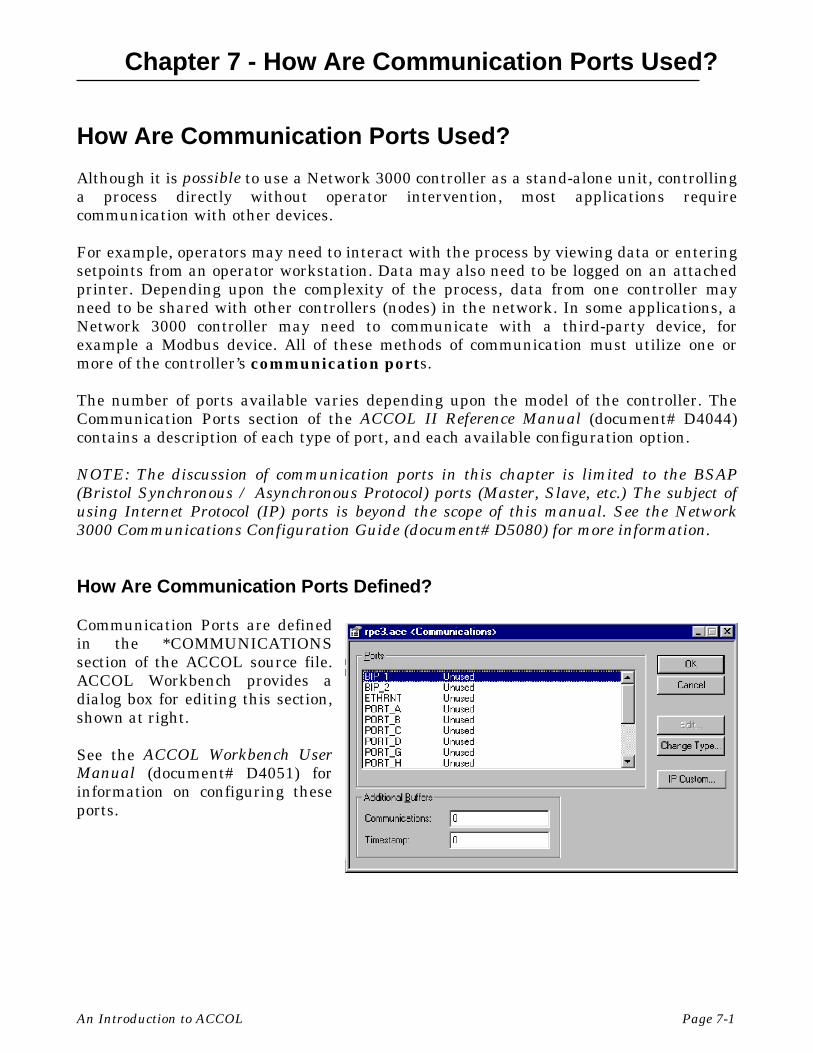
Communication Ports are definedin the *COMMUNICATIONSsection of the ACCOL source file.ACCOL Workbench provides adialog box for editing this section,shown at right.
See the ACCOL Workbench UserManual (document# D4051) forinformation on configuring theseports.

Chapter 7 - How Are Communication Ports Used?
Page 7-2 An Introduction to ACCOL
Examples of Communication Port Usage
The fictitious Bristolville Water Treatment Plant has two Network 3000 controllers“RPC1” and “RPC2” to monitor various processes throughout the plant, and a thirdNetwork 3000 controller named “DC1” at the top of the network.
“RPC1” controls the levels of awater tank. “RPC2” operates somechlorination pumps. Both “RPC1”and “RPC2” will have a Slave Portconfigured for 19,200 baudoperation. “RPC2” also has aCustom Port configured so that itcan send and receive data from achlorine analyzer unit whichcommunicates using the Modbusprotocol.
“DC1” serves as a dataconcentrator or communicationsinterface at the top of thenetwork. Any Network 3000controller with a Master Portconnected to one or more slavenodes can serve as a dataconcentrator. While a dataconcentrator is not usuallyrequired, it is useful in manysystems to make decisions basedon inputs from several slavenodes:
RPC1 and RPC2 can each control their own areas of operation; DC1 can monitor both toissue control commands to them. DC1 also acts as a communication pass-through device,and handles its own local I/O.
“DC1” will need a Master Port, to collect data from “RPC1” and “RPC2”, and a Slave Port,to send that data to an operator workstation, running Open BSI, and an HMI softwarepackage. A node such as “DC1”, which is on the level directly below the operatorworkstation, is called a top-level node. Open BSI supports multiple top-level nodes on asingle PC port, or over multiple ports.
Operator Workstation running Open BSI andHMI software
DC1
RPC1 RPC2
COM1:
Slave Port
Slave Port
Slave Port
Master Port
Custom Port
ChlorineAnalyzer

Chapter 7 - How Are Communication Ports Used?
An Introduction to ACCOL Page 7-3
The figure, above, shows the Communication Port definitions in each of the threeNetwork 3000 controllers, DC1, RPC1, and RPC2.
In addition to configuring the ports, and any necessary structures in ACCOL, each nodemust be defined in the Network Definition (NETDEF) files and Open BSIcommunications must be configured on the PC. This subject is discussed in the Open BSIUtilities Manual (document# D5081).

BLANK PAGE

Chapter 8 - What Should I Know About Memory?
An Introduction to ACCOL Page 8-1
What Should I Know About Memory?
Depending upon the application your controller will be used for; you might not need toknow anything about memory, other than there is a finite amount of it in the controller,and the more structures you put in your ACCOL load, the more memory of this finiteamount gets used.
If you are using more than the default memory configuration, or you are using certainACCOL structures (Storage Modules, Audit Trail Alarms/Events, custom portapplications) then you do need to know a little more about memory.
The next section describes a little about what memory is. If you are comfortable with thebasic concepts of Network 3000 memory, you can skip to the section called ‘WhatConfiguration Needs To Be Performed?’.
Background - What is Memory?
As a Network 3000-series controller runs its ACCOL load, the CPU (central processingunit) of the controller executes each instruction in the ACL file. These instructions, andthe data associated with them, are read from, and/or written to, physical locations withincomputer chips in the controller. These physical locations are referred to as memory.They are similar to memory you might have in your personal computer at home.
The amount of memory in your Network 3000 controller varies depending upon themodel of controller, and the purchased memory options. The amount of memory neededfor your ACCOL load varies depending upon the types of modules, control statements,and structures included in the source file.
Information in memory is stored as a series of 0’s and 1’s; each ’0’ or ’1’ is referred to as abit. These bits are grouped together into chunks of 8 which are called bytes.1 Each bytecan hold a character of data. A group of 1024 bytes is referred to as 1K. 1024K is referredto as a Megabyte or 1MB.
Types of Memory in the Controller
The size of your ACCOL load file is limited by the amount of RAM2 in the controller.
RAM in a 186-based controller, or a 386EX Real Mode controller is divided into twoparts: base memory and expanded memory. All of these controllers have 64K (65,536
1 Two bytes together are referred to as a word.2 RAM is an acronym for random access memory. It simply means memory that can be read from and
written to.

Chapter 8 - What Should I Know About Memory?
Page 8-2 An Introduction to ACCOL
bytes) of base memory, and then some amount of expanded memory.3 The expandedmemory is used to hold certain kinds of ACCOL structures which CANNOT fit in thebase memory.
RAM in a 386EX Protected Mode controller is NOT divided up into base and expanded;instead, it is treated as one large memory area. Each Protected Mode controller has atleast 512K of RAM, but can be configured for as much as 4.5 MB.
Normally, when you download your ACCOL load file into the Network 3000 controller,it is transferred directly into RAM, and on completion of the download, the controllerbegins to execute the instructions (modules, control statements, etc.) in the ACCOL load.
Execution of the ACCOL load will continue, without interruption, unless the Network3000 controller loses power, or fails (which is referred to as a watchdog condition), or itis manually reset by the operator, by activating the reset switch.
In the first case (power failure), the ACCOL load, and its data, will remain in RAM for aslong as the unit’s backup battery functions. If the battery remains good, when primarypower is restored, the unit will resume execution of the ACCOL load from the pointwhere it lost power. This is referred to as a warm start.
The second and third cases (watchdog failure, or manual reset) are referred to as coldstart conditions. In a cold start, any accumulated data (calculations, etc.) is lost. Inaddition, the ACCOL load file, itself, will only be retained if it has been previously“burned into” EPROM, or downloaded into FLASH.
EPROM stands for Erasable Programmable Read Only Memory. An EPROM chip can beplaced in a device called a PROM burner, and the ACCOL load file can be ‘burned into’the chip. If your unit has an EPROM chip with the ACCOL load ‘burned in’, the ACCOLload file (though no accumulated data) will still be present in the controller after a coldstart condition. With the exception of the RTU 3305, and the 3530-xx series, all 186-based controllers support the use of EPROMs.
Similarly, if your ACCOL load was originally downloaded into FLASH memory, prior tothe cold start condition, accumulated data will be lost, but the load file will still bepresent after the cold start. The RTU 3305, 3530-xx series, as well as 386EX Real andProtected Mode units support the use of FLASH memory.
For more information on these subjects, consult the section on Downloading in theACCOL II Reference Manual (document# D4044).
3 The amount of expanded memory available varies depending upon the type of controller.
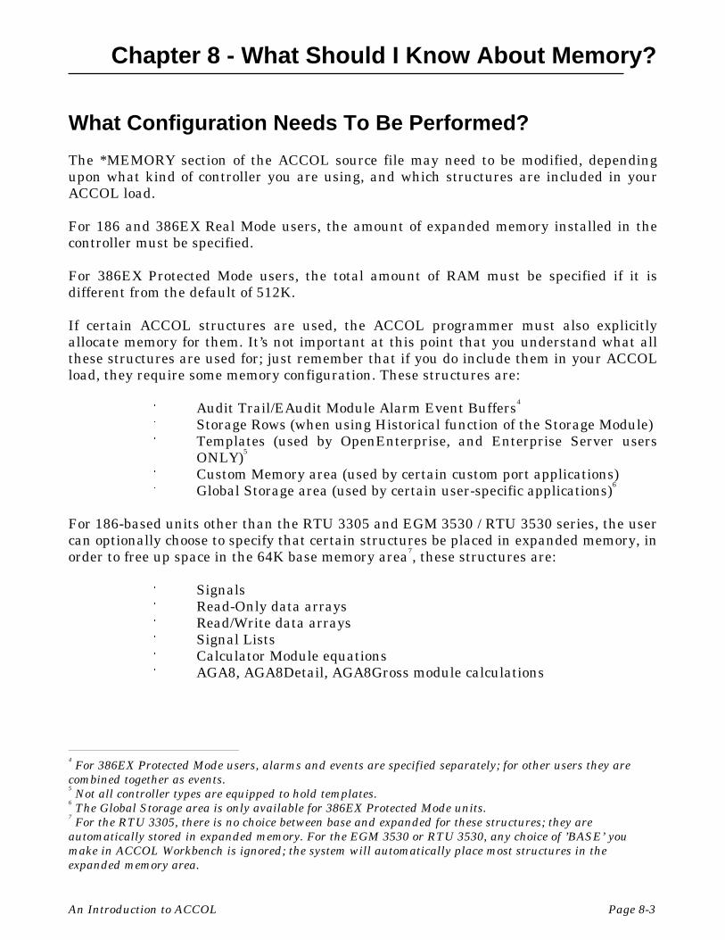
Chapter 8 - What Should I Know About Memory?
An Introduction to ACCOL Page 8-3
What Configuration Needs To Be Performed?
The *MEMORY section of the ACCOL source file may need to be modified, dependingupon what kind of controller you are using, and which structures are included in yourACCOL load.
For 186 and 386EX Real Mode users, the amount of expanded memory installed in thecontroller must be specified.
For 386EX Protected Mode users, the total amount of RAM must be specified if it isdifferent from the default of 512K.
If certain ACCOL structures are used, the ACCOL programmer must also explicitlyallocate memory for them. It’s not important at this point that you understand what allthese structures are used for; just remember that if you do include them in your ACCOLload, they require some memory configuration. These structures are:
" Audit Trail/EAudit Module Alarm Event Buffers4
" Storage Rows (when using Historical function of the Storage Module)" Templates (used by OpenEnterprise, and Enterprise Server users
ONLY)5
" Custom Memory area (used by certain custom port applications)" Global Storage area (used by certain user-specific applications)6
For 186-based units other than the RTU 3305 and EGM 3530 / RTU 3530 series, the usercan optionally choose to specify that certain structures be placed in expanded memory, inorder to free up space in the 64K base memory area7, these structures are:
" Signals" Read-Only data arrays" Read/Write data arrays" Signal Lists" Calculator Module equations" AGA8, AGA8Detail, AGA8Gross module calculations
4 For 386EX Protected Mode users, alarms and events are specified separately; for other users they are
combined together as events.5 Not all controller types are equipped to hold templates.
6 The Global Storage area is only available for 386EX Protected Mode units.
7 For the RTU 3305, there is no choice between base and expanded for these structures; they are
automatically stored in expanded memory. For the EGM 3530 or RTU 3530, any choice of ’BASE’ youmake in ACCOL Workbench is ignored; the system will automatically place most structures in theexpanded memory area.

Chapter 8 - What Should I Know About Memory?
Page 8-4 An Introduction to ACCOL
How is the Configuration Performed?
Memory configuration is performed inACCOL Workbench through the dialogbox shown at right. (The fields in thedialog box vary depending upon whichversion of ACCOL Workbench you areusing.)
For more information about this dialogbox, see the ACCOL Workbench UserManual (document# D4051).
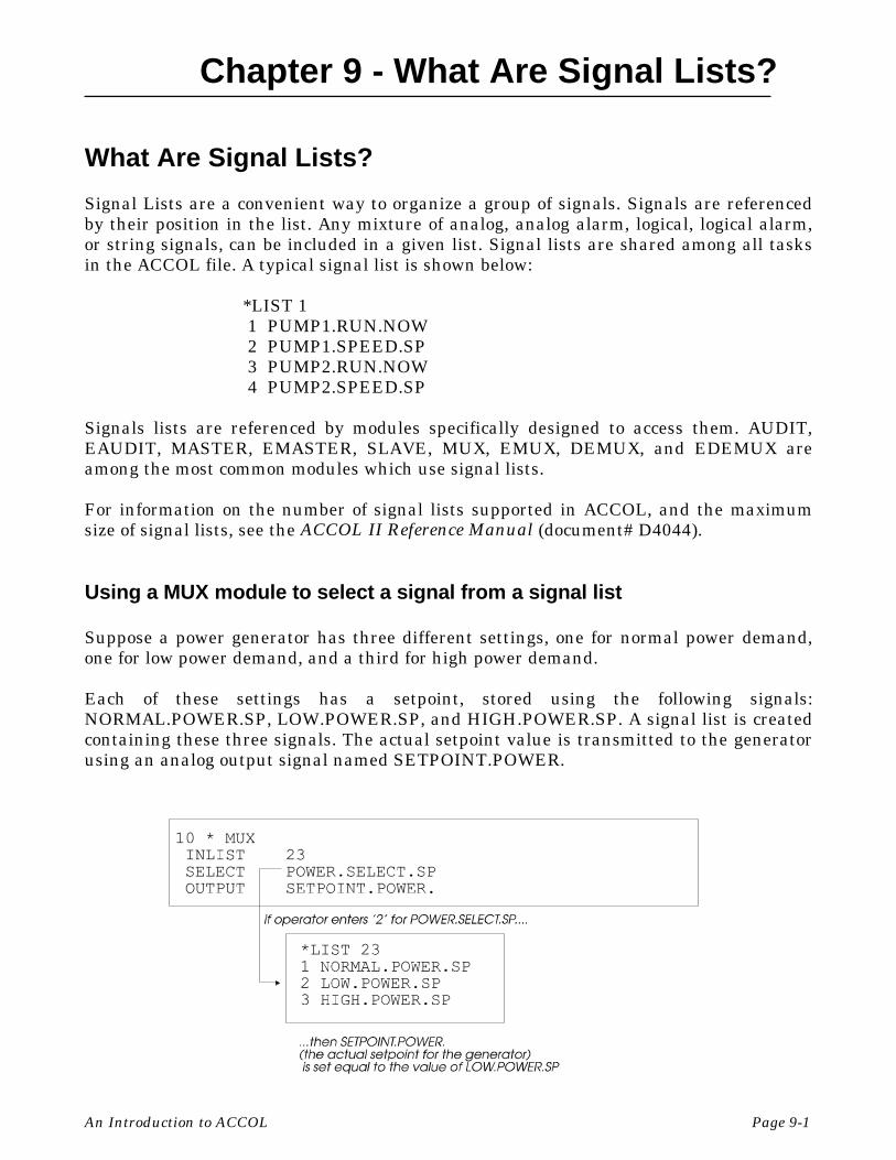
Chapter 9 - What Are Signal Lists?
An Introduction to ACCOL Page 9-1
What Are Signal Lists?
Signal Lists are a convenient way to organize a group of signals. Signals are referencedby their position in the list. Any mixture of analog, analog alarm, logical, logical alarm,or string signals, can be included in a given list. Signal lists are shared among all tasksin the ACCOL file. A typical signal list is shown below:
*LIST 1 1 PUMP1.RUN.NOW 2 PUMP1.SPEED.SP 3 PUMP2.RUN.NOW 4 PUMP2.SPEED.SP
Signals lists are referenced by modules specifically designed to access them. AUDIT,EAUDIT, MASTER, EMASTER, SLAVE, MUX, EMUX, DEMUX, and EDEMUX areamong the most common modules which use signal lists.
For information on the number of signal lists supported in ACCOL, and the maximumsize of signal lists, see the ACCOL II Reference Manual (document# D4044).
Using a MUX module to select a signal from a signal list
Suppose a power generator has three different settings, one for normal power demand,one for low power demand, and a third for high power demand.
Each of these settings has a setpoint, stored using the following signals:NORMAL.POWER.SP, LOW.POWER.SP, and HIGH.POWER.SP. A signal list is createdcontaining these three signals. The actual setpoint value is transmitted to the generatorusing an analog output signal named SETPOINT.POWER.

Chapter 9 - What Are Signal Lists?
Page 9-2 An Introduction to ACCOL
In order to allow for an operator to select which of these setpoints should be used for thegenerator at a given time, the operator can select the desired setpoint, from the signallist, using a signal called POWER.SELECT.SP. This signal specifies the position in thesignal list which be chosen as the setpoint.
The MUX module uses the POWER.SELECT.SP signal to choose which of the threesetpoints should be output to the SETPOINT.POWER. signal.
For example, if the operator chooses ‘2’ for the value of POWER.SELECT.SP, then thesecond signal in the list, called LOW.POWER.SP will be used as the setpoint.
For more information on the MUX Module, see the ACCOL II Reference Manual(document# D4044).
Using A DEMUX Module to Choose Which Signal In A List Should ReceiveAn Input Value
Suppose a water pumping station has four different pumps, only one of which should berunning at any one time. Each pump can be started/stopped by a dedicated startcommand signal. The signals are PUMP1.START.CMD, PUMP2.START.CMD,PUMP3.START.CMD, PUMP4.START.CMD.
If all of these signals are placed in a signal list, the DEMUX module can be used to selectwhich of the four pumps should be started.
The signal PUMP.START. is set to ON, and the signal PUMP.SELECT. allows theoperator to choose which of the pump command signals will be turned on byPUMP.START. The value of PUMP.SELECT specifies the position in the list which willreceive the value of PUMP.START.
For more information on the DEMUX Module, see the ACCOL II Reference Manual(document# D4044).
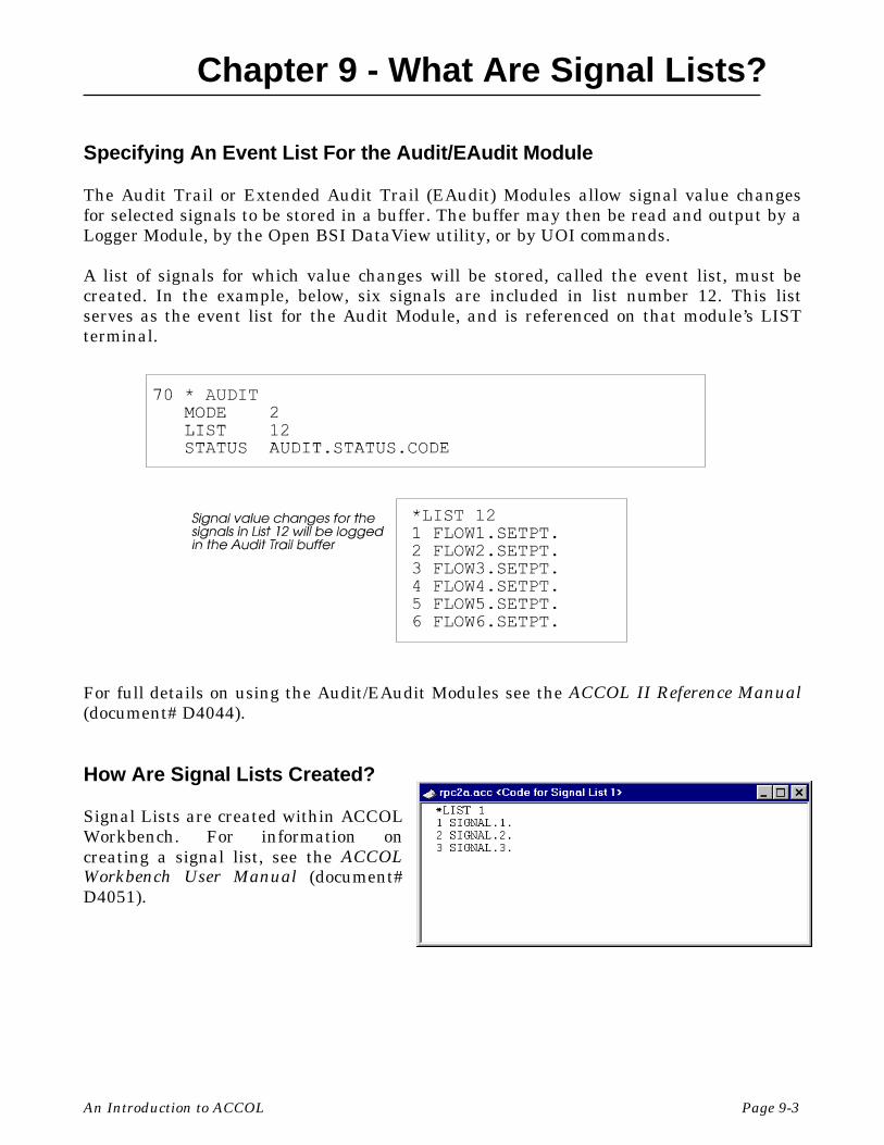
Chapter 9 - What Are Signal Lists?
An Introduction to ACCOL Page 9-3
Specifying An Event List For the Audit/EAudit Module
The Audit Trail or Extended Audit Trail (EAudit) Modules allow signal value changesfor selected signals to be stored in a buffer. The buffer may then be read and output by aLogger Module, by the Open BSI DataView utility, or by UOI commands.
A list of signals for which value changes will be stored, called the event list, must becreated. In the example, below, six signals are included in list number 12. This listserves as the event list for the Audit Module, and is referenced on that module’s LISTterminal.
For full details on using the Audit/EAudit Modules see the ACCOL II Reference Manual(document# D4044).
How Are Signal Lists Created?
Signal Lists are created within ACCOLWorkbench. For information oncreating a signal list, see the ACCOLWorkbench User Manual (document#D4051).

Chapter 9 - What Are Signal Lists?
Page 9-4 An Introduction to ACCOL
How Can The Operator View Signal Lists?
The operator can view signal lists using the Remote List feature of DataView. Theoperator can also change signal values or inhibit/enable bits. For information on thisfeature, see the Open BSI Utilities Manual (document# D5081).

Chapter 10 - What Are Archive Files?
An Introduction to ACCOL Page 10-1
What Are Archive Files?
Archive files are structures residing within the Network 3000 controller, and are verysimilar to Data Arrays (discussed earlier in this manual).1
Like arrays, archive files are tables of data, organized in rows and columns. Unlikearrays, however, each column is associated with a specific ACCOL signal, and has adescriptive title; and each row is called a record. Also, each and every archive file mustbe assigned a unique name and number.
Typically, the archive files are configured so that data wraps around, overwriting theoldest data, with newer data. The ordering of data in the Archive File is determined bysequence numbers.
How Is Data Stored In An Archive File?
Data is stored in the archive file by executing the ARC_STORE Module in one of severalavailable modes. Some modes allow calculations to be performed on data before it isstored in the archive file. Not all modes are available for all Network 3000 controllers.Full details on configuring the ARC_STORE Module, and the available modes, appear inthe ACCOL II Reference Manual (document# D4044).
A typical application would be to execute the ARC_STORE Module hourly, to storehourly totals, and then re-initialize the hourly total signals to 0 in order to accumulatenew data for the next hour. NOTE: Once a data record has been stored in the Archive 1 Not all controller, ACCOL Tools, or firmware versions support the use of archive files. To see if it is
supported, check the ’Hardware and Software Requirements’ chart of the ACCOL II Reference Manual(document# D4044) and verify that the ARC_STORE module is supported for your particularconfiguration.
Column Title:
Signal Name:
Row1
Row2
Row3
Row n
#TIME.000. STAT1.FLOW1.HRLY STAT1.PRESUR.HRLY
Date_and_Time Hourly_Flow
12/11/95 08:00
12/11/95 09:00
12/11/95 10:00
12/12/95 07:00
Archive File Name: ARCFLOW1Archive File Number: 001
85.28 73.27
85.29
72.39
85.87
83.47
75.26
74.73
Hourly_Pressure
:::

Chapter 10 - What Are Archive Files?
Page 10-2 An Introduction to ACCOL
File, and the ARC_STORE Module has advanced to the next row of the file, the data inthe Archive File cannot be altered.
How Are Archive Files Defined?
The structure of the archive file,including its name, file ID number, thenumber of records (rows), the signal foreach column, and the title for eachcolumn, are defined in the ACCOLsource file. See the ACCOL WorkbenchUser Manual (D4051) for instructionson defining an archive file.
How Does the Operator View Archive Data?
There are several different ways to access archive data in a running Network 3000 seriescontroller.
• While running the Open BSI DataView utility, users can call up the archive file forviewing on the screen. See the Open BSI Utilities Manual (document #D5081) fordetails.

Chapter 10 - What Are Archive Files?
An Introduction to ACCOL Page 10-3
• Users with Bristol Babcock’s Universal Operator Interface (UOI) software can exportarchive data values to binary files and then use the binary files to create logs. See theUOI Configuration Manual (document# D5074) for details.
• While running the Open BSI Data Collector or Open BSI Scheduler, users canretrieve archive data, and store it in files for export to third-party HMI applications.See the Open BSI Collection/Export Utilities Manual (document# D5083) and theOpen BSI Scheduler Manual (document# D5082), respectively, for details.

BLANK PAGE
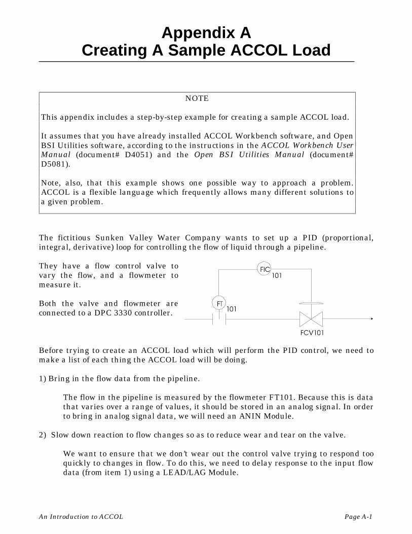
Appendix ACreating A Sample ACCOL Load
An Introduction to ACCOL Page A-1
The fictitious Sunken Valley Water Company wants to set up a PID (proportional,integral, derivative) loop for controlling the flow of liquid through a pipeline.
They have a flow control valve tovary the flow, and a flowmeter tomeasure it.
Both the valve and flowmeter areconnected to a DPC 3330 controller.
Before trying to create an ACCOL load which will perform the PID control, we need tomake a list of each thing the ACCOL load will be doing.
1) Bring in the flow data from the pipeline.
The flow in the pipeline is measured by the flowmeter FT101. Because this is datathat varies over a range of values, it should be stored in an analog signal. In orderto bring in analog signal data, we will need an ANIN Module.
2) Slow down reaction to flow changes so as to reduce wear and tear on the valve.
We want to ensure that we don’t wear out the control valve trying to respond tooquickly to changes in flow. To do this, we need to delay response to the input flowdata (from item 1) using a LEAD/LAG Module.
NOTE
This appendix includes a step-by-step example for creating a sample ACCOL load.
It assumes that you have already installed ACCOL Workbench software, and OpenBSI Utilities software, according to the instructions in the ACCOL Workbench UserManual (document# D4051) and the Open BSI Utilities Manual (document#D5081).
Note, also, that this example shows one possible way to approach a problem.ACCOL is a flexible language which frequently allows many different solutions toa given problem.

Appendix ACreating A Sample ACCOL Load
Page A-2 An Introduction to ACCOL
3) Perform the actual PID calculation.
To perform the actual PID control, we can use the pre-defined PID3TERM Module.
4) Send data to the control valve.
The controller will have to send data out to the flow control valve(FIC101/FCV101), in order to vary the position of the valve to regulate the flow.This will require an analog signal, and since it will be sent out, we will need anANOUT Module.
Now that we know, roughly, what we’re trying to do, let’s create an ACCOL load to do it:
Step 1. Start ACCOL Workbench. To do this, double-click on the Workbench icon (ifyou have one) or start it through the Windows™ Start Programs menu.
ACCOL Workbench will start:

Appendix ACreating A Sample ACCOL Load
An Introduction to ACCOL Page A-3
Step 2. Open a new ACCOL source file.To do this, click on “File” in themenu bar, and “New” in the pulldown menu. Choose ’ProtectedMode’ you are creating an ACCOLload for a controller which has the386EX Protected Mode CPU. Forany other type of controller,choose ’Real Mode’.
Click on [OK] when you’ve made your choice.
We have now opened a new ACCOL source file. A default name is displayed in the titlebar. We’ll rename it later on.
Before we do anything else, we need to define certain characteristics of the controllersuch as its memory configuration, how its ports are to be used, and which process I/Oboards are installed in it. These subjects are discussed in the next few steps.

Appendix ACreating A Sample ACCOL Load
Page A-4 An Introduction to ACCOL
Step 3. Edit the memory configuration. To do this double-click on the Memory icon,and follow the instructions below.
The *MEMORY section of theACCOL source file specifies howmuch memory is installed in thecontroller, and also can be usedto set aside memory for certainspecial structures.
Click on the “Total RAM” listbox, and select the appropriateamount of RAM installed in yourunit. Next click on the [OK]push button to exit the*MEMORY section.
Step 4. Configure the Communication Ports. To do this, double-click on the Communications icon, and follow the instructions below.
The *COMMUNICATIONS section of the ACCOL source file specifies how thecontroller’s communication ports will be used.

Appendix ACreating A Sample ACCOL Load
An Introduction to ACCOL Page A-5
We will want to define one port for communicationwith the operator workstation running Open BSIUtilities software. This should be configured as aSlave Port, which will allow us to download intothe unit. To configure Port B as a Slave Port, clickon ‘PORT_B Unused’ in the list box, then click onthe [Change Type] push button. The ChangeType dialog box will appear. Select ‘Slave’ from thelist box, and click on the [OK] push button.
The Slave Settings dialog box will appear. Usethe default baud rate of 9600, or change it usingthe “Baud Rate” list box; then click on the[OK] push button.
Another port, called a Pseudo Slave Port, will be used for local communication if atechnician wants to connect a laptop running Open BSI. Click on ‘PORT_A Unused’, anddefine a Pseudo Slave Port at 9600 baud using the same method used, above, for defininga Slave Port.
Finally, it’s a good idea to set aside some extra communication buffers.1 Type ‘20’ in the“Communications” field under “Additional Buffers”.
When finished, the windowshould appear as shown at right;click on the [OK] push button toexit the *COMMUNICATIONSsection.
1 Buffers are discussed in detail in the ACCOL II Reference Manual (document# D4044).

Appendix ACreating A Sample ACCOL Load
Page A-6 An Introduction to ACCOL
Step 5. Configure the Process I/O. To do this, double-click on the Process-I/O icon,and follow the directions below.
The *PROCESS-I/O section ofthe ACCOL source filespecifies what type of processI/O boards are installed in thecontroller. For purposes of ourexample, our controller musthave an Analog Input boardand an Analog Output boardinstalled.
Let’s say the Analog output board has 2 I/O points, and is in slot 1, and the Analog Inputboard has 4 I/O points, and is in Slot 2. A ‘1’ already appears in the “Board ID” field.Choose ‘Analog Output board : 2 points’ from the “Board Type” list box, then click onthe [Insert] push button. Next, enter ‘2’ in the “Board ID” field, and select ‘AnalogInput board : 4 points’ from the “Board Type” field, and click on the [Insert] pushbutton. When finished, the dialog box should look as shown, above. Click on the [OK]push button to exit the *PROCESS-I/O section.
Step 6. Define signals.
Now that we’ve defined the characteristics of the controller, let’s get to work on theproblem at hand - - controlling the flow in the pipe.
To start off, let’s create some signals. We know that we need an analog signal for theincoming flow data. To create this signal, double-click on the Signals icon.

Appendix ACreating A Sample ACCOL Load
An Introduction to ACCOL Page A-7
The Specify Signal Filter dialog box willappear. This dialog box lets you limit whichtypes of signals are displayed in the Signalwindow.
Just click on the [OK] push button. An empty signals window will appear.
Click on “Edit” in the menu bar,and “Insert” in the pull down menu,and the Signal Properties dialog boxwill appear. Choose ‘Analog’ fromthe “Type” list box, and type ‘F101’in the “Base Name” field, ‘IN’ in the“Extension” field, and ‘NL’ in the“Attribute” field.
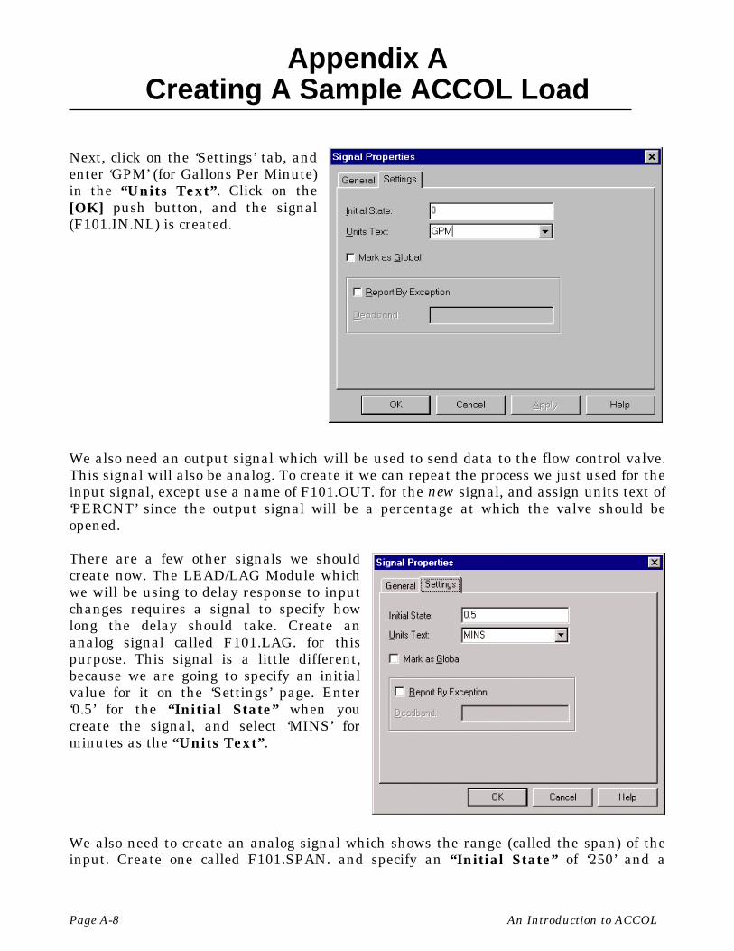
Appendix ACreating A Sample ACCOL Load
Page A-8 An Introduction to ACCOL
Next, click on the ‘Settings’ tab, andenter ‘GPM’ (for Gallons Per Minute)in the “Units Text”. Click on the[OK] push button, and the signal(F101.IN.NL) is created.
We also need an output signal which will be used to send data to the flow control valve.This signal will also be analog. To create it we can repeat the process we just used for theinput signal, except use a name of F101.OUT. for the new signal, and assign units text of‘PERCNT’ since the output signal will be a percentage at which the valve should beopened.
There are a few other signals we shouldcreate now. The LEAD/LAG Module whichwe will be using to delay response to inputchanges requires a signal to specify howlong the delay should take. Create ananalog signal called F101.LAG. for thispurpose. This signal is a little different,because we are going to specify an initialvalue for it on the ‘Settings’ page. Enter‘0.5’ for the “Initial State” when youcreate the signal, and select ‘MINS’ forminutes as the “Units Text”.
We also need to create an analog signal which shows the range (called the span) of theinput. Create one called F101.SPAN. and specify an “Initial State” of ‘250’ and a

Appendix ACreating A Sample ACCOL Load
An Introduction to ACCOL Page A-9
“Units Text” of ‘GPM’, just like the input signal F101.IN.NL.
We need to create an analog signal which represents the desired operator setpoint forflow in the pipe. Create one called F101.SET. and specify an “Initial State” of ‘125’ anda “Units Text” of ‘GPM’, just like the input signal F101.IN.NL.
We also need to create a few signals which will be used by the PID3TERM Module. Bothare analog, and both require initial values of ‘1’. They should be named F101.P. andF101.I.
After inserting all of these signals, the Signals window should appear as shown below:
We will need to do more with signals later, so leave the Signals window on the screen, butclick on the main window (the one containing all the icons for Memory, Communications,etc.) and let’s go on to our next step - - building an ACCOL task.
GENERAL NOTE ABOUT DEFINING SIGNALS:
The user has the option of explicitly defining signals in the *SIGNALS section (as we aredoing here) or of simply entering them on module terminals (which will be discussed in alater step.)
Defining them explicitly allows the user to have full control over the signal type, initialvalue, etc., and allows them to be ‘dragged and dropped’ to desired module terminals.
In contrast, if signals are defined simply by typing on the module terminal, they assumewhatever signal type is the default for that terminal. The default signal type, however,may or may not be appropriate for the particular user application.
Either or both methods may be used.

Appendix ACreating A Sample ACCOL Load
Page A-10 An Introduction to ACCOL
Step 7. Create an ACCOL Task, and include Modules in it.
To create a Task, click on “Edit” in the menubar, and “Insert” in the pull down menu. Clickon ‘Task’ in the New Section dialog box, andclick on the [OK] push button.
A dialog box similar to the one shown below should appear.
This dialog box allows you to configure certain characteristics of the task. By default, thetask shows a task rate of 0, a task priority of 1, and a redundancy frequency of 0. This isnot a redundant controller, so the redundancy frequency should be 0. Also, since we’reonly defining one task, we don’t care that its priority is 1. We do need to change the taskrate to something other than 0, or else the task will never execute. To do this, change the‘0.0’ to ‘0.2’ in the dialog box, and click on [OK]. The first line of the task will now bedisplayed, as shown below:

Appendix ACreating A Sample ACCOL Load
An Introduction to ACCOL Page A-11
Now, let’s start inserting modules in our task.From our previous discussion, we know we need toget the data in using an ANIN module. Let’sspecify that first. To do so, click on the second lineof the task (so as not to interfere with theinformation on the first line), and click on“Modules” in the menu bar, and “Insert..” in thepull down menu. The Select Module dialog box willappear. Click on ‘ANIN’ in the list box, then clickon the [OK] push button.
NOTE: Before selecting certain I/O modules (ANIN, DIGIN, etc.) you need to specify thenumber of I/O terminals in the "Number of Terminals" field. For this example,however, we only need one analog input, which is the default, so we can just leave thedefault of '1' in the "Number of Terminals" field.
The ANIN Module appears inthe task window. The DEVICEline specifies which slot theANIN Module should reference.
Because our Analog Input Board is in Slot 2, we must erase the word 'DEVICE_ID' andspecify a ‘2’ in its place.
Next, erase the word ‘CHANNEL’ and enter ‘1’ (this specifies that we are starting withthe first I/O point on the board.
The module contains a single set of INPUT, ZERO, and SPAN terminals. If we wereusing additional analog input points on the board, we would have specified that numberin the "Number of Terminals" field when we inserted the module. (If you forget to dothat, you can just copy additional sets or simply type them in). Since, for this example,we have only one analog input value, we just have to define that.

Appendix ACreating A Sample ACCOL Load
Page A-12 An Introduction to ACCOL
With the Signalswindow visible, clickand drag the signalnamed ‘F101.IN.NL’to the INPUTterminal of themodule. (You couldalso just erase‘;ANALOG_SIGNAL’and just type‘F101.IN.NL’, butdragging the namewill save you a fewkeystrokes.)
Next drag F101.SPAN. to the SPAN terminal, in the same way. (Or type it.)
Type F101.ZERO. on the ZERO terminal. (We didn’t define it previously, so we can’tdrag it from the Signals window. Because the default initial value of all analog signals is0, it wasn’t necessary to define it separately.)
Together, the signals on the ZERO and SPAN terminals are used to specify the range ofvalid values for the INPUT signal. ZERO represents the lowest value, and SPAN isadded to that value to determine the highest value. For this signal (F101.IN.NL), itsrange is 0 to 250 GPM. Note that we could have simply entered constant values forZERO and SPAN, but then they could not be changed on-line.
When finished, the ANIN module should appear as shown:
Drag signal from here
To here

Appendix ACreating A Sample ACCOL Load
An Introduction to ACCOL Page A-13
Next, let’s insert the LEAD/LAG Module, which will be used to delay the rate at whichinput fluctuations are responded to. Place the cursor on the line immediately followingthe end of the ANIN module, and use the same technique used for inserting the ANINmodule, except insert a LEAD/LAG module.
It should appear as shown in thewindow at right.
Drag F101.IN.NL from the Signals window to the INPUT terminal of the LEAD/LAGModule (or just type it). In doing this, we have ‘wired’ the ANIN and LEAD/LAG modulestogether!
Next, drag the signal named F101.LAG. to the INTEGRAL terminal. The F101.LAG.signal will allow the operator to specify a ‘lag time’, in minutes, so that changes in themodule input F101.IN.NL will be reacted to gradually, so as to reduce wear on thecontrol valve.
Type ‘F101.IN.’ on the OUTPUT terminal. This signal will be used to reflect a gradualchange of the input (based on the lag time.) For example, if F101.IN.NL quickly changesfrom 1 to 5, and F101.LAG. is three minutes, then the value of F101.IN. will gradually‘ramp up’ from 1 to 5 over a three minute period. We didn’t need to explicitly createF101.IN. in the Signals window, earlier, because it will automatically be classified as ananalog signal based on the context in which it is used; and it has no initial value.
Leave the DERIVATIVE and RESET terminals alone.
When you’re finished, the LEAD/LAGModule should appear as shown.

Appendix ACreating A Sample ACCOL Load
Page A-14 An Introduction to ACCOL
Now insert a PID3TERM Module after the LEAD/LAG Module. The INPUT to themodule is the F101.IN. signal from the LEAD/LAG Module, so type that name on theINPUT terminal on PID3TERM.
Drag the signal F101.I. from the Signals window to the INTEGRAL terminal of thePID3TERM module (or just type the name).
Drag the signal F101.P. from the Signals window to the PROPORTION terminal of thePID3TERM module (or just type the name).
Drag the signal F101.SET from the Signals window to the SETPOINT terminal of thePID3TERM module (or just type the name).
Type F101.D. on the DERIVATIVE terminal of the PID3TERM module. (We didn’t createit earlier, so we can’t drag it in.) This signal may be used by the operator to determinehow much the change of the input should affect the output of the module.
Type F101.OUT. on the OUTPUT terminal. Again, this is analog, based on its usage. It isthe actual output that will be sent to the control valve.
Type F101.RESET. on the RESET terminal, and F101.TRACK. on the TRACK terminal.F101.RESET. is an analog signal, based on its usage, and F101.TRACK. is a logicalsignal, based on its usage. These signals are used by the module to prevent the OUTPUTterminal from going out of range.
The ERROR and DEADBANDterminals can be left alone. Thefinished PID3TERM Moduleshould appear as shown atright.
Finally, we need to insert an ANOUT Module, in order to send the analog output data,out to the control valve. Follow the same method, used previously, for inserting modules.
Type a ‘1’ on both the DEVICE and INITIAL terminals of the ANOUT Module. Thiscauses the module to reference the first process I/O slot in the controller, which weidentified in Step 5, as an Analog Output board, and the first output point on that board.
Type the signal name F101.TRACK. on the TRACK terminal, F101.RESET. on theRESET terminal, and F101.OUT. on the OUTPUT terminal.

Appendix ACreating A Sample ACCOL Load
An Introduction to ACCOL Page A-15
Type in a value of ‘0’ on the ZERO terminal. This represents the 0% output for the flowcontrol valve.
Type in a value of ‘100’ on the SPAN terminal. This represents the 100% output for theflow control valve.
The completed ACCOL task should appear as follows:
Step 8.
Save the ACCOL source file. Click on“File” in the menu bar, and “Save As”in the pull down menu. Enter a filename in the “File Name” field (in thiscase we used the name ‘myload’) andclick on the [OK] push button. Youredits will be saved in a file with theextension (.ACC).
Step 9. Issue a ‘Build’ command, if errors are present, correct them and repeat step
*TASK 1 RATE: 0.200000 PRI: 110 * ANIN
DEVICE 2INITIAL 1INPUT 1 F101.IN.NLZERO 1 F101.ZERO.SPAN 1 F101.SPAN.
20 * LEAD/LAGINPUT F101.IN.NLDERIVATIVE ;ANALOG_SIGNAL_OR_VALUEINTEGRAL F101.LAG.RESET ;LOGICAL_SIGNALOUTPUT F101.IN.
30 * PID3TERMINPUT F101.IN.SETPOINT F101.SET.DEADBAND ;ANALOG_SIGNAL_OR_VALUEPROPORTION F101.P.INTEGRAL F101.I.DERIVATIVE F101.D.RESET F101.RESET.TRACK F101.TRACK.OUTPUT F101.OUT.ERROR ;ANALOG_SIGNAL
40 * ANOUTDEVICE 1INITIAL 1OUTPUT 1 F101.OUT.ZERO 1 0SPAN 1 100TRACK 1 F101.TRACK.RESET 1 F101.RESET.
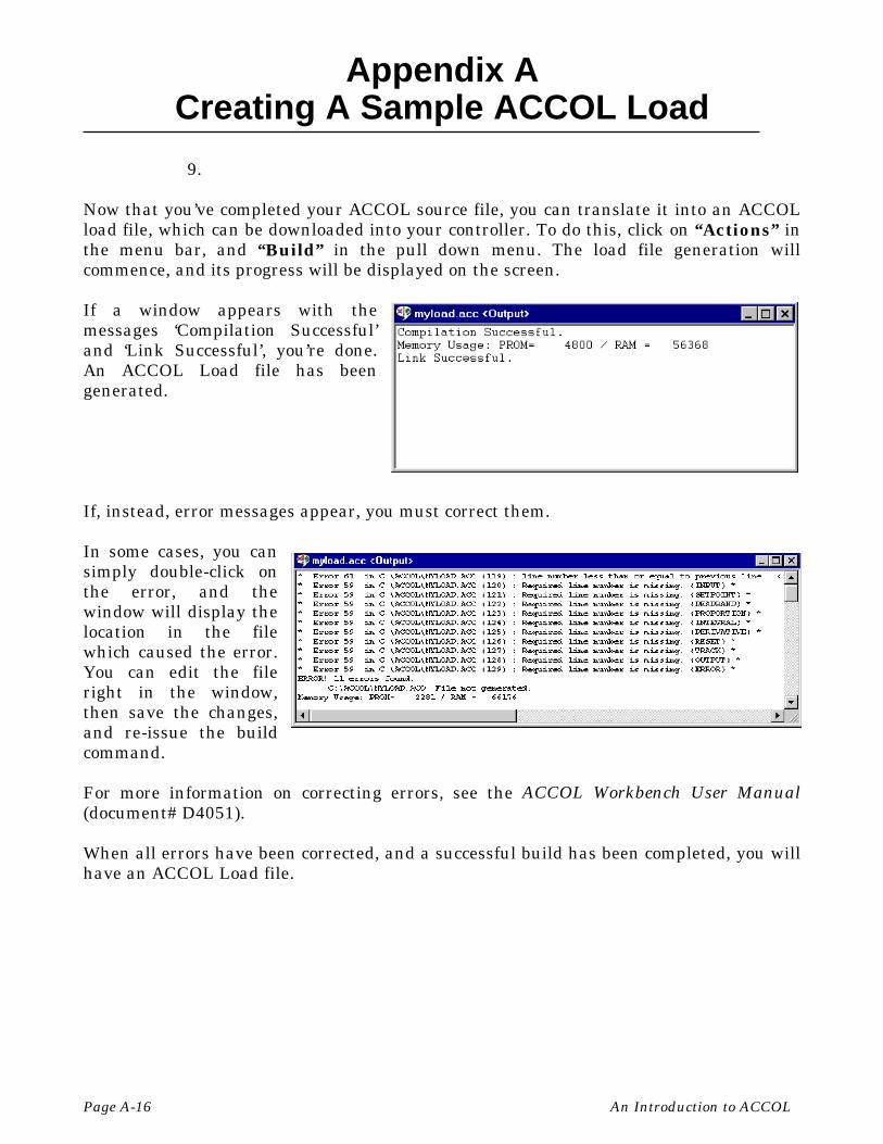
Appendix ACreating A Sample ACCOL Load
Page A-16 An Introduction to ACCOL
9.
Now that you’ve completed your ACCOL source file, you can translate it into an ACCOLload file, which can be downloaded into your controller. To do this, click on “Actions” inthe menu bar, and “Build” in the pull down menu. The load file generation willcommence, and its progress will be displayed on the screen.
If a window appears with themessages ‘Compilation Successful’and ‘Link Successful’, you’re done.An ACCOL Load file has beengenerated.
If, instead, error messages appear, you must correct them.
In some cases, you cansimply double-click onthe error, and thewindow will display thelocation in the filewhich caused the error.You can edit the fileright in the window,then save the changes,and re-issue the buildcommand.
For more information on correcting errors, see the ACCOL Workbench User Manual(document# D4051).
When all errors have been corrected, and a successful build has been completed, you willhave an ACCOL Load file.
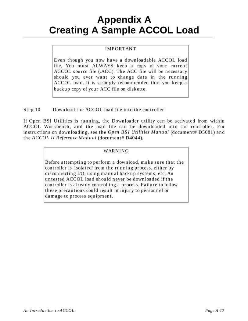
Appendix ACreating A Sample ACCOL Load
An Introduction to ACCOL Page A-17
Step 10. Download the ACCOL load file into the controller.
If Open BSI Utilities is running, the Downloader utility can be activated from withinACCOL Workbench, and the load file can be downloaded into the controller. Forinstructions on downloading, see the Open BSI Utilities Manual (document# D5081) andthe ACCOL II Reference Manual (document# D4044).
IMPORTANT
Even though you now have a downloadable ACCOL loadfile, You must ALWAYS keep a copy of your currentACCOL source file (.ACC). The ACC file will be necessaryshould you ever want to change data in the runningACCOL load. It is strongly recommended that you keep abackup copy of your ACC file on diskette.
WARNING
Before attempting to perform a download, make sure that thecontroller is ‘isolated’ from the running process, either bydisconnecting I/O, using manual backup systems, etc. Anuntested ACCOL load should never be downloaded if thecontroller is already controlling a process. Failure to followthese precautions could result in injury to personnel ordamage to process equipment.

BLANK PAGE

Appendix BWorking with Floating Point Numbers
An Introduction to ACCOL Page B-1
All digital computers represent numbers as a series of 0’s and 1’s. Each ’0’ or ’1’ isreferred to as a ’bit’. ACCOL analog (floating point) signals in Bristol Babcock’s Network3000-series controllers use 32 such bits, and these bits are organized according to thesingle-precision IEEE floating point standard.
This industry standard provides compatibility and the necessary degree of accuracy formost applications.
When single-precision floating point numbers are added, however, the smaller numberwill lose precision if the difference between the exponent of the most significant digit ofthe larger number of the expression, and the exponent of the least significant digit in thesmaller number of the expression, is greater than 7. Here are some examples to clarifythis rule:
Say a metering station is recording accumulated flow totals in an analog signal. Thecurrent total number of gallons is 623.71. A new reading of 12.274 gallons is to be addedto the total.
The most significant digit in the larger number is the 6 in 623.71. Shown in exponentialnotation it is 6 * 102. Similarly the least significant digit in the smaller number is the 4in 12.274 or 4 * 10-3. The difference between the exponents is 5, i.e. 2 - (-3) = 5. Since thisis not greater than 7, there is no loss of precision, and the result is 635.984.
As a second example, say we have a station accumulating the amount of natural gasflowing in a pipeline. The accumulated total for the month is 8,384,983.0 cubic feet. Anadditional 25.443 cubic feet must be added to the total.
The most significant digit in the larger number is the leftmost 8 in 8,384,983.0. Shown inexponential notation it is 8 * 106. The least significant digit in the smaller number is the3 in 25.443 or 3 * 10-3. The difference between the exponents is 9, i.e. 6 - (-3) = 9. Sincethis is greater than 7, the smaller number will lose some precision, and will be added as25.375, causing the result to be 8,385,008.375.
The loss of the smaller number’s least significant digits is unavoidable under the IEEEsingle precision floating point standard. When the smaller number is scaled, bits 'dropoff the end' of the scaled result.
If the magnitude of the larger number exceeds that of the smaller number by 16,777,216then the smaller number will be zero after scaling, and it will not add to theaccumulation at all. So adding 1.0 to 16,777,216 will fail, as will adding 2 to 33,554,432,or 0.25 to 4,194,304.
This problem is inherent in any computer using this format to represent numbers, from

Appendix BWorking with Floating Point Numbers
Page B-2 An Introduction to ACCOL
your hand-held calculator, to a large mainframe system.
For most applications, however, this is not a major concern, since many instrumentscannot support such precise measurements, and many industrial applications frequentlydo not require such precision.
Work-Arounds For This Situation
Don’t Accumulate Totals Indefinitely
One way to prevent this kind of situation is to limit the size of accumulations.
If, for example, you are performing accumulations which can get large, and add smallincrements to it, say, an equipment runtime measurement using the Command Module’sRUNTIME terminal, you might want to ‘zero out’ the runtime every month, after savingthe monthly total in a signal which can be used later as part of a yearly runtimeaccumulation.
Use Double-Precision Modules, Where Necessary
Another way to lessen the impact of these problems is to use modules which supportdouble-precision calculations. Double-precision calculations allow many more bits forrepresenting numbers, internally. Note, however, that they too can eventually run out ofspace for displaying full precision - - it just takes much longer to run out.
Among the modules which support double-precision internal calculations are theAverager, ETOT/TRND, TOT/TRND, and EIntegrator. The output of these modules isstill a single-precision value, but it is based on the more accurate double-precisioninternal calculations.
The Daccumulator also allows double-precision operations, but its output is two single-precision numbers which, when combined, provide an approximation of a double-precision number. See the Daccumulator section of the ACCOL II Reference Manual(document# D4044) for details.
If you have more questions concerning these subjects, contact Bristol BabcockApplication Support for help.
G-1
Glossary
ACCOL is an acronym for Advanced Communications andControl-Oriented Language. It is the standard softwareprogramming language for Bristol Babcock Network3000-series controllers.
AccolCAD is a software package, available from Bristol Babcock,which allows an ACCOL source file to be created usinggraphical symbols.
ACCOL Load also known as the .ACL file, is created from an ACCOLObject file. It is called the ACCOL Load file because it isin a machine-readable format which is downloaded intothe Network 3000-series controller. Once downloaded, thecontroller executes instructions in the ACCOL load file inorder to measure or control a plant or process.
ACCOL Object File also known as the .ACO file, is created from an ACCOLsource file. The ACO file is used by ACCOL Workbench togenerate an ACCOL Load file.
ACCOL Source File also known as the .ACC file, is created by the ACCOLprogrammer using ACCOL Workbench, AccolCAD, or byusing any ASCII text editor. The ACCOL source filedefines the modules, task, signals, and other ACCOLstructures which define the measurement and controlinstructions for this particular application. The ACCOLsource file, when finished, is used to generate an ACCOLObject file, and ACCOL Load file.
ACCOL Task(s) is a series of modules and control statements whichexecute sequentially as a functional block. Task executionoccurs at a user-specified rate and priority.
ACCOL Tools is a set of software programs which includes ACCOLWorkbench, ValScan, and DIAG6.
ACCOL Workbench is a Windows-based software program which allows you tocreate an ACCOL source file, and to build an ACCOLobject file, and ACCOL load file from it.
Alarm Limit is a number, associated with an analog alarm signal,which determines (in combination with a deadband value)when the signal is in an alarm state.

G-2
Alarm Message is a communications message, generated when an analogor logical signal enters an alarm state. Alarm messagesare passed up through the network to MMI software atthe operator workstation, to notify the operator that analarm condition exists.
Alarm Priority is a user-defined classification for the importance of agiven alarm signal. ‘Critical’ is the most important alarmpriority, followed in descending order of importance, by‘Non-Critical’, ‘Operator Guide’, and ‘Event’ alarms.
ASCII is an acronym for American Standard Code forInformation Interchange. This refers to characters of text.
Base Memory is a term which applies to 186-based and 386EX RealMode controllers only. Each of these types of units has64K of base memory which holds most ACCOL structures.386EX Protected Mode units do NOT use the term ‘basememory’.
Bit A value of ‘0’ (OFF) or ‘1’ (ON). Bits are used to representinformation in computers.
BSAP Bristol Synchronous Asynchronous Protocol.
Byte A group of 8 bits.
Character string A collection of alpha numeric information. For example“PUMP NUMBER 4” is a string of 13 characters (whichincludes spaces.)
Cold Start is a condition in which the Network 3000 controller haslost all accumulated data, either because of a watchdogfailure, or because the operator has pressed the unit’sreset button. Upon cold start, the unit will wait for a newACCOL load to be downloaded, unless one already hasbeen stored in EPROM or FLASH memory.
Communication Ports these are devices on the Network 3000 controller, whichallow the controller to exchange data with othercontrollers and devices.
Control Statement(s) these are statements which may be included in anACCOL Task to modify the execution of the task.Common control statements include SUSPEND,RESUME, ABORT, IF, ENDIF, etc.

G-3
Data Array(s) these are tables of values. Arrays can contain eitherlogical values (1 for ON, 0 for OFF), or floating pointanalog values.
Data Concentrator This is a Network 3000 controller which has a MasterPort, through which it accepts data from one or moreslave controllers. Data concentrators are typically usedwhen ACCOL control decisions must be made based ondata from more than one controller.
Deadband this is a value used to provide a range, above or below analarm limit, (or RBE value, in the case of RBE signals) inwhich the alarm state (or RBE report status) will notchange.
DIAG6 is one of the ACCOL Tools. It is also called the 33XXDiagnostics Program. It is used to test certain parts of theNetwork 3000 controller hardware.
Download is the process of transferring an ACCOL load file into thememory of a Network 3000-series controller. Downloadingis performed using the Open BSI Downloader.
DPC Distributed Process Controller. See Remote ProcessControllers
EPROM Erasable Programmable Read-Only Memory.
Expanded Memory is extra memory, beyond the base memory, which isinstalled in a 186 or 386EX Real Mode controller. Thismemory is used to hold certain selected ACCOLstructures which may be shifted out of base memory, tofree up space in the base memory area. In addition, thereare certain structures which can only exist in expandedmemory. The term expanded memory does NOT apply to386EX Protected Mode controllers.
FLASH is a type of memory used in some types of Network 3000controllers which allows an ACCOL load file (but notdata) to be retained even after a cold start condition.
Human-MachineInterface (HMI) this is a software package, such as OpenEnterprise,
Intellution® FIX®, or Iconics Genesis, which is used todisplay and report data for an operator.

G-4
LocalView is an Open BSI utility which allows local communicationwith a controller. It also allows the user to perform fieldupgrades of controller firmware for certain controllermodels.
Memory is the part of the Network 3000 controller which holds theACCOL load file, and accumulated data.
Module are pre-programmed structures which are used to performmathematical, communication, and process controlfunctions in ACCOL. Modules are inserted into ACCOLtasks in a logical order, and are connected together usingsignals.
Module Terminal(s) are used to specify the inputs, or outputs of a module.Signals (or in some cases, constant values) are entered onmodule terminals. By entering the same signal name ontwo different terminals, those terminals are said to be‘wired’ together.
NETBC5 is one of the ACCOL Tools. It is also called the NetworkBatch Compiler. This program takes an ASCII file anduses it to generate the Network file NETFILE.DAT.NOTE: Open BSI 3.0 or newer users MUST use NetViewinstead.
NETREV5 is one of the ACCOL Tools. It is also called the NetworkReverse Compiler. This program takes the NETFILE.DATfile, and converts it into an editable ASCII file. NOTE:Open BSI 3.0 or newer users MUST use NetView instead.
NETTOP5 is one of the ACCOL Tools - - also known as the NetworkTopology Program. It allows the user to define thestructure of the controller network including networklevels, addresses, etc. The NETTOP files containing thisinformation are NETFILE.DAT, GLADXREF.DAT, andRTUXREF.DAT. NOTE: Open BSI 3.0 or newer usersMUST use NetView instead.
NetView a program in Open BSI used to define yourcommunication network, and to start communications.See the Open BSI Utilities Manual (document# D5081)for details.
Network 3000 a product name for a family of Bristol Babcock digitalremote process controllers and related equipment.

G-5
Node a Network 3000 controller which is part of a network ofcontrollers.
Open BristolSystem Interface see Open BSI
Open BSI stands for Open Bristol System Interface. Open BSI is aset of software utility programs which facilitate datacollection and communications with a network of BristolBabcock Network 3000-series controllers. The utilities inthe standard Open BSI set include NetView, LocalView,DataView, and the Downloader.
Points these are input/output (I/O) connections on a process I/Oboard.
Pre-emptiveMulti-Tasking a method in which multiple ACCOL tasks execute
concurrently, however, those with higher priority arealways executed first.
Process I/O the input/output (I/O) data from a process or plant. Thisdata comes from devices such as meters, pressureswitches, temperature transmitters, etc. This type of datacomes into the controller through Process I/O boards.
Process I/O boards these are hardware devices, installed in slots in theNetwork 3000 controller, which are used to send andreceive process I/O data. See Process I/O.
RAM Random Access Memory. This is memory that can be bothread from, and written to.
Read-only this is data in memory which is fixed; i.e. it cannot bechanged by an operator on-line.
Read Priority this is the security level, required by an operator orprogram, to read signal data.
Read/Write this is data in memory which can be either read, orchanged.
Redundant this refers to a configuration in which two Network 3000controllers are linked together in a way in which one canassume the duties of the other, if the other controllerfails.

G-6
Remote ProcessControllers also known simply as ‘remotes’. These are essentially a
type of computer which is used to measure or control aprocess. (Typical examples of processes includecontrolling flow in a natural gas pipeline, measuringliquid level in a tank, or controlling a factory productionline.) Bristol Babcock’s Network 3000 series of remoteprocess controllers includes the DPC 3330, DPC 3335,RTU 3305, RTU 3310, etc. These units collect data,perform calculations, and issue control commands to theprocess. The term ‘remote’ is sometimes used to refer tocontrollers because they are often installed at locationsthat are physically distant from the operator workstation.Other synonymous terms include ‘RTU’ or ‘DPC', or'33XX'. See also Node.
RTU Remote Terminal Unit. See Remote Process Controllers
Signal is a software structure which is used to pass data frommodule to module in an ACCOL load. They are similar to‘variables’ or ‘tags’ in other programming languages. TheACCOL programmer enters a signal name on a moduleterminal. By placing the same signal name on a terminalof a different module, the modules are said to be ‘wired’together, and data can pass between them; i.e. the valueof a signal on an output terminal of one module becomesan input to another module, and so on. There are fivetypes of signals in ACCOL: Logical, Logical Alarm,Analog, Analog Alarm, and String.
Signal List a signal list is a way to group signals together. Signalsare referenced by their position in the list. SeveralACCOL modules are available for referencing signal lists.
Supervisory Controland
Data Acquisition (SCADA) is a method of process control in which a supervisory
computer, typically running MMI software, collects datafrom a network of remote process controllers, displays thedata for an operator, and allows the operator to issuecommands which are sent out to control the process.
System Signals these are special ACCOL signals (distinguished by a ‘#’ asthe first character in the signal base name) which arecreated by the system for various housekeeping purposes.

G-7
They may be used by the ACCOL programmer, but cannotbe created or deleted by the ACCOL programmer.
Task see ACCOL Task(s)
Task Control Statements see Control Statements
Task Priority is a value, assigned by the ACCOL programmer, to eachACCOL Task. This value is used to determine which taskshould execute next. Priorities can range from 1 to 64.Tasks which perform important calculations should begiven higher priorities.
Task Rate specifies how often an ACCOL task is scheduled to beginexecution. If a particular task has a task rate of 1 second,for example, then it will begin executing every second. If atask cannot complete execution prior to its next scheduledexecution, its execution will be delayed until the previousexecution has completed; this situation is called ‘slippage’,and indicates that the task rate has been set too fast.
Terminals see Module terminals
Top Level Node(s) a Network 3000 controller in a BSAP network, which ison the network level immediately below the operatorworkstation running Open BSI. Also known as a ‘firstlevel node’ or ‘first level slave’.
Warm Start if a Network 3000 controller suffers a power failure, andpower is restored prior to failure of the backup battery,the ACCOL load will resume execution from the pointwhere it lost power.
Watchdog a failure condition, indicated by the Watchdog (WDOG)LED on the controller. A Network 3000 controller in awatchdog state must be reset, and possibly re-downloadedin order to function again.
Word A unit of measurement representing two bytes of memory.
Write Priority this is the security level, required by an operator orprogram, to change signal data.

BLANK PAGE

READER RESPONSE FORM
Please help us make our documentation more useful to you! If you have acomplaint, a suggestion, or a correction regarding this manual, please tell us bymailing this page with your comments. It’s the only way we know we’re doing ourjob by giving you correct, complete, and useful documentation.
DOCUMENT NUMBER: D4056TITLE: An Introduction to ACCOLISSUE DATE: January, 2001
COMMENT/COMPLAINT:
______________________________________________________________________________
______________________________________________________________________________
______________________________________________________________________________
______________________________________________________________________________
______________________________________________________________________________
______________________________________________________________________________
______________________________________________________________________________
______________________________________________________________________________
______________________________________________________________________________
______________________________________________________________________________
______________________________________________________________________________
______________________________________________________________________________
______________________________________________________________________________
Mail or FAX this page to:Bristol Babcock Inc.1100 Buckingham StreetWatertown, CT 06795FAX#: (860) 945-2213Attn: Technical Publications Group, Dept. 610 RRF - 1/2001

&VMWXSP�&EFGSGO�-RG�an FKI company
1100 Buckingham StreetWatertown, CT 06795
Telephone: (860) 945-2200