amo incremental _angle_encoder_catalog
TRANSCRIPT
AMO GmbH
Incremental ANGLE MEASURING SYSTEMS based on the AMOSIN® – Inductive Measuring Principle
ELECTROMATEToll Free Phone (877) SERVO98
Toll Free Fax (877) SERV099www.electromate.com
Sold & Serviced By:

2
This document was created very carefully. If there are any technical changes, they will promptly updated in the docu-ments on our website www.amo-gmbh.com
With the publication of this brochure all previous editions become invalid.
The currently valid brochure is available on our website www.amo-gmbh.com
SN: WMI-P 20130821ELECTROMATE
Toll Free Phone (877) SERVO98Toll Free Fax (877) SERV099
Sold & Serviced By:
3
Table of contents
General informations
General information .............................................................................................. 4
Selection table .................................................................................................... 8
AMOSIN measuring systems for outside scanning
MeasuringflangesWMF ....................................................................................... 10
Measuring rings WMR .......................................................................................... 16
Miniature scanning heads with external electronics WMK .................................... 19
Scanning heads with integrated electronics WMK ................................................ 25
AMOSIN measuring systems for inside scanning
Measuring rings WMR .......................................................................................... 37
Miniature scanning heads with external electronics WMK .................................... 41
Scanning heads with integrated electronics WMK ................................................ 47
AMOSIN measuring systems with multiple head scanning
Description of multiple head scanning .................................................................. 55
Measuring systems MHS / CHS ........................................................................... 62
General technical data
Maximum speed ................................................................................................... 67
Reference marks .................................................................................................. 69
Output signals ....................................................................................................... 70
Cable .................................................................................................................... 71
Connector electronics ........................................................................................... 72
Plug and connection assignments ........................................................................ 73
ELECTROMATEToll Free Phone (877) SERVO98
Toll Free Fax (877) SERV099www.electromate.com
Sold & Serviced By:

4
AMOSIN - WinkelmesssystemeAMOSIN - angle measuring systems
Allgemeine InformationenGeneral informations
AMO‘s proven and original technology for length and angle measurements uses techniques for scanning high precision graduations consisting of structures photo-lithographically etched onto steel. Based on this, inductive sensors and integrated evaluation electronics (ASIC) have been developed to create a new and powerful generation of measuring systems.
The AMOSIN® angle measuring systems are open hollow-shaft measuring systems, and generally therefore do not have their own bearings, nor do they require any couplings for mechanical connection. Operating entirely on an inductive basis, with AMOSIN® systems high system accuracies less than +/-2µm arc length and better can be achieved. Nevertheless AMOSIN®systemsareverywellabletoresistenvironmentalinfluencessuch as dust, humidity and so forth, and also feature extremely high resistance to shock and vibration.
The high precision is mainly due to the procedure used to manufacture the rigid steel measuring ring, and to the exceptionally high quality sensor signal, with deviations in the sine wave down to < 0.1 % harmonic content, as a measure of the achievable interpolation precision within the grat-ing pitch. As will be seen from the measuring principle described below, the measuring system does not include any magnetic parts (either in the scale or in the scanning head). As a result it is not at all sensitive to electromagnetic interference of any kind and has no hysteresis in contrast to magnetic measuring systems. The systems output interfaces either 1 Vpp sine/cosine signals, or RS-422 square wave signals, in real-time.
The wide range of available AMOSIN®anglemeasuringsystemtypesmeansthattheycanbeusedforlargeapplicationfieldsfromtheslow,ex-tremely precise positioning of a turntable through to the high speeds and the closely controlled velocities of a machine spindle. They are of value in general for drives where high dynamic range and stiffness is required.
General properties
Not sensitive to soiling - IP67 ■
Notsensitivetointerferingmagneticfields ■
High precision and resolution ■
Speed up to 70000 rpm ■
Operation temperature -10°C to 100°C ■
Analog output signals (1 Vpp) with divided signal period till ■15µm
Digital output RS-422 / TTL with resolution till 0,125µm arc ■length
Self-centring scanning unit ■
Integrated reference pulse, also distance coded ■
Typical applications
Turntables ■
Swivelling axes ■
C-axes ■
Working spindles ■
Direct drives ■
Sheet metal working machines ■
Medical equipment ■
Printing machines ■
Roller positioning ■
Punching machines ■
Electronic production equipment ■
Radar antennas ■
AMOSIN® - General information
ELECTROMATEToll Free Phone (877) SERVO98
Toll Free Fax (877) SERV099www.electromate.com
Sold & Serviced By:

5
Allgemeine InformationenGeneral informations
AMOSIN - WinkelmesssystemeAMOSIN - angle measuring systems
AMOSIN® - Measuring principleThe AMOSIN® measuring systems function on the principle of a transformer with a moving reluctance core. The mutual induc-tance of the primary and secondary windings of a transformer changes in accordance with the relative position of the core. The AMOSIN® system consists primarily of a planar coil and a Mea-suringscale(Fig.1).Thecoilstructure,withanumberofwindingelements (individual main elements with primary and second-ary SIN/COS coils) aligned in the direction of measurement, is implemented on a substrate using micro-multi-layer technol-ogy. The measuring scale is a stainless-steel ring onto which ahighly precise graduations (e.g. λ = 1000µm) of variable re-luctance has been etched using photo-lithographic techniques.
The relative angular movement in the direction of measure-ment between the sensor structure (in the scanning head) and the Measuring scale(measuring flange) periodically changesthe mutual inductance of the individual coils, generating two si-nusoidal signals with a 90° phase difference (SIN and COS). The extremely accurate signal, and its immunity to environ-mental influences, has the effect that, after conditioning of thesignal in the evaluation electronics (Fig. 2), deviations of nomore than 0.1% from the ideal sinusoidal form (harmonic con-tent) remains. This allows high interpolation factors (further levels of sub-dividing ) to be car ried out in the course of sig-nal digitisation. This can either be done in the measuring system itself, or in the subsequent electronics (CNC etc.).
An important feature of the principle of operation is that using the AMOSIN® procedure does not give rise to any measurement hysteresis (machine backlash error). In contrast to magnetic systems, the high-frequency alternating field suppresses any hysteresis in the material.
The evaluation electronics conditions the sensor signals and interpolates them continuously, without using strobe times, exploiting a novel circuit principle. It then supplies the measurement information at the output through differential interfaces and linedrivers, either as a sinusoidal signal or as a square wave signal. (See the signal diagram on Page 69)
In addition to the periodic quadrature signals (A, B and their inverted) a reference signal is output for the determination of absolute position. This signal is generated from individual marks integrated into the measuring ring, and does not require any additional parts. (See the description of the reference signal on Page 68).
Analog output~ 1 Vpp
Encoder output
RS 422
EEPROMConfiguration data
Power supply unit
ASIC signalconditioning+ evaluation
Compensation signals
Measuringscale
Electronic evaluation stageSensor unit
Measuring head
AMOSIN MEASURING SYSTEM (Fig. 2)
ELECTROMATEToll Free Phone (877) SERVO98
Toll Free Fax (877) SERV099www.electromate.com
Sold & Serviced By:

6
AMOSIN - WinkelmesssystemeAMOSIN - angle measuring systems
Allgemeine InformationenGeneral informations
Measuring accuracyAs an open angle-measuring system, in which the system components, measuring scale and scanning head are supplied separately, that means there is no mechanical connection requiring own bearings. Therefore the precision can be assigned to these components as follows:
1.Scaleaccuracy-determinedbytheprecisionoftheMeasuringscaleonthemeasuringflange,andbydeviationsofthemeasuringflangemechanics from an ideal cylindrical form
2. Precision within one grating pitch - primarily determined by the quality of the sensor signal and the evaluation electronics of the scanning head.
The following should also be considered for the measuring systems with a 1 Vpp output interface:
3. Precision of the analog/digital conversion at the input stage of the subsequent electronics (in the controller) 4. Noise coupled into the output signals as it is transferred from the scanning head to the subsequent electronics
A detailed description of these aspects follows:
1. Scale accuracy
Everymeasuringflangeismeasuredonanangletestbench,andatestcertificate,quotingtheprecisionclassinaccordancewithspecification,iscompleted.Althoughtheabsoluteangulardeviationforanopenmeasuringsystemdependsontheprecisionwithwhichthemeasuringflangeiscentred on the axes being measured, it is to possible supply a measuring diagram (registered under ideal assembly conditions), as follows.
Forapplicationsrequiringthegreatestprecision,themeasuringflangeshouldbecentredasaccuratelyaspossible.Theprecisionoftheangularmeasurement depends on the graduation error and on the concentricity of the assembly. Systematic (long-wave) errors resulting from this can be compensated for in the controller.
Systematic errors as for example eccentricity can be eliminated completely by using the MHS or CHS angle measuring system (see also page 55).
2. Precision within the grating pitch
The periodical deviation which appears within the grating pitch is less than 0,1% of the pitch because of the high quality of the sensor signal and the signal evaluation (e.g.. maximum deviation is 0,5µm on a 500µm pitch).Thishighaccuracylevelwillbeachievednotjustfortheideal,nominalmountingandenvironmentalconditionsbutforthewholespecifiedfunctio-nal range of geometrical mounting deviations or temperature.
In order to suppress the errors discussed above under points „3“ and „4“, a new output interface has been implemented in the new generation of AMOSIN® systems, in which the sine, cosine and reference signals, for the 1 Vpp output interface delivered over line drivers (see signal diagram on Page 69).
Therealtimeconversionoftheoriginalsignal(e.g.1000µm)infinersinewaveperiodsdownto10µm.arclengthisrealisedoveraprogrammablefactor „D“. The effect of any possible deviation in the evaluation of the encoder signals in the subsequent electronics (controller etc.), is reduced exactlybythedividingfactor(D)thatisapplied.Inaddition,thisreducedsinusoidalsignalperiodleadstofinerquantisationinthesubsequentelectronics, which is of particularly great importance to demanding high stability, high stiffness drive applications. Additionally, the signal dividing reduces the effect of interfered noise on the signal transfer line in proportion to the dividing factor „D“; in other words, an improved signal/noise ratio is achieved.
The metrological principle on which the AMOSIN® systems operate means that they are entirely free from hysteresis and don´t lead to a “backlash effect”.
ELECTROMATEToll Free Phone (877) SERVO98
Toll Free Fax (877) SERV099www.electromate.com
Sold & Serviced By:

7
Allgemeine InformationenGeneral informations
AMOSIN - WinkelmesssystemeAMOSIN - angle measuring systems
Measuring system configurationAn angle measuring system for inside or outside scanning consists of a measuring ring and a scanning head with integrated electronics or external connector electronics (see selection table on page 8).
A special manufacturing technology is used to produce the scale in the form of a closed measuring ring. This, in turn, is related in two variants, as rigidlymountedontoaWMF-typemeasuringflange,orasathinWMR-typemeasuringring,forassemblybythecustomer.
ImplementingthenewmeasuringscaleWMRasathin,closedringforthemeasurementofanglesorrotationspeedsoffershighflexibilitytodrivedesign.
Fittingthemeasuringringinthetransmissionchainturnsanexistingpartofthemachineintoameasuringflange.
Other advantages of the measuring ring design:
Extremely low inertia ■
Thepartofthespindleontowhichthemeasuringringisfittedcanconsistofanymaterial ■
High rotation speeds can be achieved due to the extremely stable structure of the ring. ■
The design of the sensor unit (Fig.3) is unique to the AMOSIN® angle measuring systems.
The planar coil structure, consisting of a number of coil elements, is applied to a flexible substrate, so that its ra-dius can therefore be adapted to any requireddiameterof(measuringflan-ge).
With this arrangement, it is ideally pos-sible Measuring to average the signal over several grating flange pitches.A plane scanning surface, such as a glass plate or a rigid silicon substrate, incorporating individual sensitive ele-ments, can only approximate to this, and is therefore less suitable for scan-ning a cylindrically arranged scale.
These angle measuring systems are used wherever precision is required under difficult environmental condi-tions (e.g. oil, dust, coolant and so forth - protection class IP 67).
A speciality of these measuring sys-tems is the ease with which it can be integrated into customers existing mechanics, regardless of whether the mechanical parts are supplied to us for integration of the measuring ring, or whether AMO manufactures the special mechanical parts, incorpora-ting the scale body, in accordance with customers‘ drawings.
The design of the measuring system based on the basic components:
The measuring system is based on two basic components, the measuring scale and the measuring head. These two components can be adapted tothespecialrequirementsofanyparticularapplicationinaveryflexibleway.Themainselectioncriteriaaregivenfurther.(Seealsoselectiontable page 8)
Generally speaking, any type of measuring scale can be combined with any measuring head as long as the following properties for the two components match:
Grating pitch ■
Type of scanning ■
Number of grating pitches per revolution ■
ELECTROMATEToll Free Phone (877) SERVO98
Toll Free Fax (877) SERV099www.electromate.com
Sold & Serviced By:
8
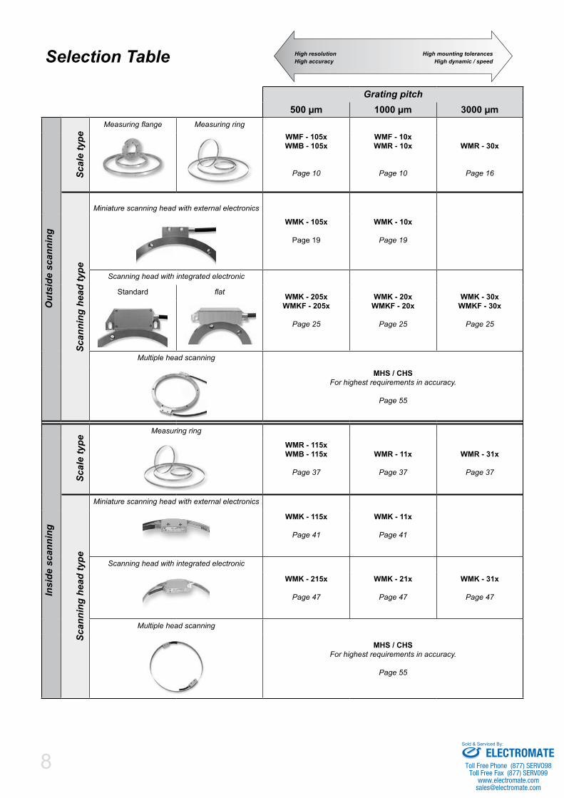
Selection Table
Grating pitch500 µm 1000 µm 3000 µm
Out
side
sca
nnin
g
Scal
e ty
pe
Measuringflange Measuring ringWMF - 105xWMB - 105x
Page 10
WMF - 10xWMR - 10x
Page 10
WMR - 30x
Page 16
Scan
ning
hea
d ty
pe
Miniature scanning head with external electronics
WMK - 105x
Page 19
WMK - 10x
Page 19
Scanning head with integrated electronic
WMK - 205xWMKF - 205x
Page 25
WMK - 20xWMKF - 20x
Page 25
WMK - 30xWMKF - 30x
Page 25
Standard flat
Multiple head scanning
MHS / CHSForhighestrequirementsinaccuracy.
Page 55
Insi
de s
cann
ing
Scal
e ty
pe
Measuring ring
WMR - 115xWMB - 115x
Page 37
WMR - 11x
Page 37
WMR - 31x
Page 37
Scan
ning
hea
d ty
pe
Miniature scanning head with external electronics
WMK - 115x
Page 41
WMK - 11x
Page 41
Scanning head with integrated electronic
WMK - 215x
Page 47
WMK - 21x
Page 47
WMK - 31x
Page 47
Multiple head scanning
MHS / CHSForhighestrequirementsinaccuracy.
Page 55
High resolutionHigh accuracy
High mounting tolerancesHigh dynamic / speed
ELECTROMATEToll Free Phone (877) SERVO98
Toll Free Fax (877) SERV099www.electromate.com
Sold & Serviced By:

9
Grating pitches 500 µm, 1000 ■µm, 3000 µmCan be combined with all scan- ■ning heads of the same grating pitchesMeasuring flanges and measu- ■ring rings – standard sizes or customizedNo magnetic components, ■no Hysteresis
Measuring flanges and rings for outside scanning
ELECTROMATEToll Free Phone (877) SERVO98
Toll Free Fax (877) SERV099www.electromate.com
Sold & Serviced By:

10
Messflansche und MessringeMeasuring flanges and rings
AußenabtastungOutside scanning
Standard measuring flanges for outside scanning
Measuringflangeswith500µmor1000µmgratingpitchofferedasstandardsizesasshowninthetablebelow.CustomerspecificdesignsforthemeasuringflangecanbesuppliedbyAMOorthemeasuringflangewillbesuppliedbythecustomerformountingthe measuring ring at AMO (see page 12 for details).The accuracies shown below can be increased by a factor of 4 using MHS or CHS as a measuring system (see page 55).
Technical data
WMF-105x WMF-10x WMF-30x
Grating pitch [arc length]: 500 µm 1000 µm 3000 µm
Grating accuracy [arc length]: ± 10 µm, ± 5 µm oder (or) ± 3 µm ± 20 µm, ± 10 µm oder (or) ± 5 µm
Mechanical execution: Stainlesssteelmeasuringflangein2versions:
WMF-105x-xxxx-0WMF-105x-xxxx-1
WMF-10x-xxxx-0WMF-10x-xxxx-1
WMF-30x-xxxx-0WMF-30x-xxxx-1
Reference mark: 1 mark / 360° as standard or any desired number and position or distance coded (see page 68)
Standard sizes N: 0512, 0720,1024, 1440, 1800, 2048
0256, 0360. 0512, 0720, 0900, 1024 0120, 0240, 0300
N … Grating pitches per revolution
Dimensions WMF-10x / WMF-105x
ß
M6
0,1
X
ØB
0,00
5
11 ±0,05
5,2
0,5x
45°
0,5x
45°
4,5 4,5
2 0+0,5
0,1
DETAIL X M 2:1
ØA
Ø I
0,00
5A
0,00
5
A
0 -0,0
1
+0,1
0
Measuring flanges WMF-100 / WMF-1050
ELECTROMATEToll Free Phone (877) SERVO98
Toll Free Fax (877) SERV099www.electromate.com
Sold & Serviced By:

11
AußenabtastungOutside scanning
Messflansche und MessringeMeasuring flanges and rings
Standard measuring flanges, grating pitch 1000µm
TypeWMF-10x
Ø A[mm]
Ø I[mm]
Ø B[mm] β
Scale accuracyWMF-100 WMF-101 WMF-102
0256-1 81,95 60 +0-0,01 70 6 x 60° ±50” ±25” ±15“
0360-0 115,12 60 +0-0,01 75
6 x 60° ±36” ±18” ±10“0360-1 115,12 95 +0
-0,01 105
0512-0 163,54 105 +0-0,01 120
6 x 60° ±24” ±12” ±7,5“ 0512-1 1) 163,54 143 +0
-0,01 153
0720-0 229,78 180 +0-0,01 195
6 x 60° ±18” ±9” ±5,4“ 0720-1 1) 229,78 209 +0
-0,01 219
0900-0 287,08 180 +0-0,01 195
12 x 30° ±14” ±7” ±4,3“ 0900-1 1) 287,08 266 +0
-0,01 276
1024-0 326,55 220 +0-0,01 235
12 x 30° ±12” ±6” ±3,8“ 1024-1 1) 326,55 296 +0
-0,01 3111) Onlyforpress-fittassemblyonthecustomersshaft(recommendedshafttolerance+0,02/+0,01)
Grating pitches / revolution (N)
RI - Position
00 ........ none01 ........ 1 RI / revolutionKxx ...... Distance-coded (basic spacing xx grating pitches)
Inner diameter (see drawing above)
0 .......... small1 .......... large
Grating accuracy
0 ... ± 10 µm arc length 1 ... ± 5 µm arc length 2 ... ± 3 µm arc length
WMF-10 - - -
WMF-105 - - -
Standard measuring flanges, grating pitch 500µm
TypeWMF-105x
Ø A[mm]
Ø I[mm]
Ø B[mm] β
Scale accuracyWMF-1050 WMF-1051 WMF-1052
0512-1 81,85 60 +0-0,01 70 6 x 60° ±50” ±25” ±15“
0720-0 115,02 60 +0-0,01 75
6 x 60° ±36” ±18” ±10“0720-1 115,02 95 +0
-0,01 105
1024-0 163,44 105 +0-0,01 120
6 x 60° ±24” ±12” ±7,5“ 1024-1 1) 163,44 143 +0
-0,01 153
1440-0 229,68 180 +0-0,01 195
6 x 60° ±18” ±9” ±5,4“ 1440-1 1) 229,68 209 +0
-0,01 219
1800-0 286,98 180 +0-0,01 195
12 x 30° ±14” ±7” ±4,3“ 1800-1 1) 286,98 266 +0
-0,01 276
2048-0 326,45 220 +0-0,01 235
12 x 30° ±12” ±6” ±3,8“ 2048-1 1) 326,45 296 +0
-0,01 311
ELECTROMATEToll Free Phone (877) SERVO98
Toll Free Fax (877) SERV099www.electromate.com
Sold & Serviced By:

12
Messflansche und MessringeMeasuring flanges and rings
AußenabtastungOutside scanning
Dimensions WMF-30x
ß
M6
0,1
X
ØB
0,00
5
15 ±0,05
5,2
0,1
0,5x
45°
0,5x
45°
6,5 6,5
2 0+0,5
DETAIL X M 2:1
ØA
0,00
5A
0,00
5
A
ØI 0 -0
,01 +0
,1 0
Standard measuring flanges, grating pitch 3000µmType
WMF-30xØ A
[mm]Ø I
[mm]Ø B
[mm] βScale accuracy
WMF-300 WMF-301 WMF-3020120-0 115,12 60 +0
-0,01 756 x 60° ±72” ±36” ±18“
0120-1 115,12 95 +0-0,01 105
0240-0 229,78 180 +0-0,01 195
6 x 60° ±36” ±18” ±9“ 0240-1 1) 229,78 209 +0
-0,01 219
0300-0 287,08 180 +0-0,01 195
6 x 60° ±28” ±14” ±7“ 0300-1 1) 287,08 266 +0
-0,01 2761) Onlyforpress-fittassemblyonthecustomersshaft(recommendedshafttolerance+0,02/+0,01)
Grating pitches / revolution (N)
RI - Position
00 ........ none01 ........ 1 RI / revolutionKxx ...... Distance-coded (basic spacing xx grating pitches)
Inner diameter (see drawing above)
0 ..........small1 ..........large
Grating accuracy
0 ... ± 20 µm arc length 1 ... ± 10 µm arc length 2 ... ± 5 µm arc length
WMF-30 - - -
Ordering code: WMF-30x
ELECTROMATEToll Free Phone (877) SERVO98
Toll Free Fax (877) SERV099www.electromate.com
Sold & Serviced By:

13
AußenabtastungOutside scanning
Messflansche und MessringeMeasuring flanges and rings
Technical data
WMF-105x / WMB-105x WMF-10x / WMB-10x WMF-30x / WMB-30x
Grating pitch [arc length]: 500 µm 1000 µm 3000 µm
Grating accuracy [arc length]: ± 10 µm, ± 5 µm oder (or) ± 3 µm ± 20 µm, ± 10 µm oder (or) ± 5 µm
Mechanical execution: Customerspecific,recommendedmaterial1.4104 or 1.7225 (42CrMo4)
Reference mark: 1 mark / 360° as standard or any desired number and position or distance coded (see page 68)
Mechanical design for WMF-105x / WMB-105x
WMF-105x / WMB-105x
0,5-1
15°
0,5
0,8
>11
ØF
ØS
= Ø
F+ 0
,45±
0,05
Ø
S L
änge
>4m
mFr
eira
um fü
r Abt
astk
opf
kee
p fre
e fo
r>4m
m M
easu
ring
head
wid
th
GratfreiBurr free
3,2
0,00
5*0,
005*
A
0,01 AA
l
Recommended material: 1.4104 oder (or) 1.7225 (42CrMo4)Please contact AMO if using other soft magnetic material.
Grating pitch [arc length]: 500 µmN ØF [mm]
512 bis (to) 719 N/2π – 0,14 ±0,01
720 bis (to) 1023 N/2π – 0,07 ±0,01
1024 bis (to) 1439 N/2π – 0,03 ±0,02
1440 bis (to) 2049 N/2π – 0,00 ±0,02
2050 bis (to) 3000 N/2π + 0,02 ±0,03
3001 bis (to) 4000 N/2π + 0,05 ±0,06
4001 bis (to) 6000 N/2π + 0,08 ±0,07
06001 bis (to) 10000 N/2π + 0,10 ±0,10
N: Integer number of grating pitches per revolution
*) Recommended eccentricity: Greater eccentricities up to ~0,03mm do not affect the function of the device, but cause a proportional loss in positioning accuracy.
CustomerspecificdesignsforthemeasuringflangecanbesuppliedbyAMO(TypeWMF)orthemeasuringflangewillbesuppliedbythecustomerfor mounting the measuring ring at AMO (Type WMB). In this case the diameter for mounting the measuring ring can be calculated as shown in the table on the next page.The accuracies shown below can be increased by a factor of 4 using MHS or CHS as a measuring system (see page 55).
Customer specific measuring flanges for outside scanning
TheproductiondrawingforthecarrierflangecanbereleasedbyAMO.
Forapplicationswithlargediametersorsignificantvariationsintemperatureduringoperationthesystemmustbedesignedaccordingly.
ELECTROMATEToll Free Phone (877) SERVO98
Toll Free Fax (877) SERV099www.electromate.com
Sold & Serviced By:

14
Messflansche und MessringeMeasuring flanges and rings
AußenabtastungOutside scanning
Mechanical design for WMF-10x / WMB-10x
WMF-10x / WMB-10x
0,5-1
15°
0,5
0,8>11
ØF
ØS
= Ø
F+ 0
,65±
0,05
Ø
S L
änge
>4m
mFr
eira
um fü
r Abt
astk
opf
kee
p fre
e fo
r>4m
m M
easu
ring
head
wid
th
GratfreiBurr free3,2
0,00
5*0,
005*
A
0,01 AA
l
Recommended material: 1.4104 oder (or) 1.7225 (42CrMo4)Please contact AMO if using other soft magnetic material.
Grating pitch [arc length]: 1000 µmN ØF [mm]
256 bis (to) 359 N/π – 0,24 ±0,01
360 bis (to) 511 N/π – 0,17 ±0,01
512 bis (to) 719 N/π – 0,13 ±0,02
0720 bis (to) 1024 N/π – 0,10 ±0,02
1025 bis (to) 1500 N/π – 0,08 ±0,03
1501 bis (to) 2000 N/π – 0,05 ±0,06
2001 bis (to) 3000 N/π – 0,02 ±0,07
3001 bis (to) 6000 N/π – 0,00 ±0,10
> 6000 N/π + 0,05 ±0,10
N: Integer number of grating pitches per revolution
*) Recommended eccentricity: Greater eccentricities up to ~0,05mm do not affect the function of the device, but cause a proportional loss in positioning accuracy.
Ordering code - customer specific designs for WMF-105x / WMB-105x
Ordering code - customer specific designs for WMF-10x / WMB-10x
Grating pitches / revolution (N)
RI - Position
00 ........ none01 ........ 1 RI / revolutionKxx ...... Distance-coded (basic spacing xx grating pitches)
Customer specific design
xx ........ numberdefinedbyAMO
Grating accuracy
0 ... ± 10 µm arc length 1 ... ± 5 µm arc length 2 ... ± 3 µm arc length
WMF-105 S- - -
WMB-105 S- - -
Grating pitches / revolution (N)
RI - Position
00 ........ none01 ........ 1 RI / revolutionKxx ...... Distance-coded (basic spacing xx grating pitches)
Customer specific design
xx ........ numberdefinedbyAMO
Grating accuracy
0 ... ± 10 µm arc length 1 ... ± 5 µm arc length 2 ... ± 3 µm arc length
WMF-10 S- - -
WMB-10 S- - -
ELECTROMATEToll Free Phone (877) SERVO98
Toll Free Fax (877) SERV099www.electromate.com
Sold & Serviced By:
15
AußenabtastungOutside scanning
Messflansche und MessringeMeasuring flanges and rings
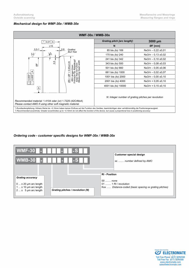
Mechanical design for WMF-30x / WMB-30x
WMF-30x / WMB-30x
0,5-1
15°
>150,8
0,5
ØS
= Ø
F +
0,65
±0,0
5
ØS
Län
ge>2
mm
Frei
raum
für A
btas
tkop
f k
eep
free
for>
2mm
Mea
surin
g he
ad w
idth
GratfreiBurr free
0,00
5*0,
005*
A
0,01 A
A
l
ØF
3,2
Recommended material: 1.4104 oder (or) 1.7225 (42CrMo4)Please contact AMO if using other soft magnetic material.
Grating pitch [arc length]: 3000 µmN ØF [mm]
85 bis (to) 169 Nx3/π – 0,22 ±0,01
170 bis (to) 240 Nx3/π – 0,13 ±0,02
241 bis (to) 342 Nx3/π – 0,10 ±0,02
343 bis (to) 500 Nx3/π – 0,08 ±0,03
501 bis (to) 660 Nx3/π – 0,05 ±0,06
0661 bis (to) 1000 Nx3/π – 0,02 ±0,07
01001 bis (to) 2000 Nx3/π – 0,00 ±0,10
02001 bis (to) 4000 Nx3/π + 0,05 ±0,10
04001 bis (to) 10000 Nx3/π + 0,15 ±0,10
N: Integer number of grating pitches per revolution
*) Rundlaufempfehlung: Höhere Werte bis ~0,10mm haben keinen Einfluss auf die Funktion des Gerätes, beeinträchtigen aber verhältnismäßig die Positioniergenauigkeit.*) Recommended eccentricity: Greater eccentricities up to ~0,10mm do not affect the function of the device, but cause a proportional loss in positioning accuracy.
Ordering code - customer specific designs for WMF-30x / WMB-30x
Grating pitches / revolution (N)
RI - Position
00 ........ none01 ........ 1 RI / revolutionKxx ...... Distance-coded (basic spacing xx grating pitches)
Customer special design
xx ........ numberdefinedbyAMO
Grating accuracy
0 ... ± 20 µm arc length 1 ... ± 10 µm arc length 2 ... ± 5 µm arc length
WMF-30 S- - -
WMB-30 S- - -
ELECTROMATEToll Free Phone (877) SERVO98
Toll Free Fax (877) SERV099www.electromate.com
Sold & Serviced By:

16
Messflansche und MessringeMeasuring flanges and rings
AußenabtastungOutside scanning
Measuring rings for outside scanning
Technical data
Grating pitch [arc length]: 1000 µm 3000 µm
Type: WMR-10x WMR-30xGrating accuracy [arc length]: ± 10 µm, ± 5 µm oder (or) ± 3 µm ± 20 µm, ± 10 µm oder (or) ± 5 µm
Mechanical execution: Stainless steel measuring ring
Flange material: No special material required
Reference mark: 1 mark / 360° as standard or any desired number and position or distance coded (see page 68)
Standard sizes N: 0256, 0360. 0512, 0720, 0900, 1024, 1440, 2048 0120, 0128, 0170,0240, 0256, 0300
0341, 0360, 0480, 0512
N … Grating pitches per revolution
Thin,stainlesssteelmeasuringring,consistingofasteelcarrierring,agraduationringandaprotectionring.Easilypressfittedmountingtothecorrespondingflangebythecustomer.(seemountinginstructionatwww.amo-gmbh.com)
Forspecialapplicationsthemeasuringring(circularsegmentalsopossible)canbemountedonaflangeatthefactory(seepage12).
WMR-10x WMR-30x
10
0,65
F
InnendurchmesserInner diameter
14
0,65
F
InnendurchmesserInner diameter
ELECTROMATEToll Free Phone (877) SERVO98
Toll Free Fax (877) SERV099www.electromate.com
Sold & Serviced By:
17
AußenabtastungOutside scanning
Messflansche und MessringeMeasuring flanges and rings
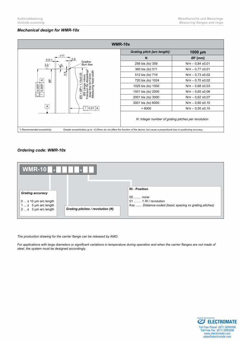
Mechanical design for WMR-10x
WMR-10x
0,5-1
15°
0,5
0,8>11
ØF
ØS
= Ø
F+ 1
,15±
0,05
Ø
S L
änge
>4m
mFr
eira
um fü
r Abt
astk
opf
kee
p fre
e fo
r>4m
m M
easu
ring
head
wid
th
GratfreiBurr free3,2
0,00
5*0,
005*
A
0,01 AA
l
Grating pitch [arc length]: 1000 µmN ØF [mm]
256 bis (to) 359 N/π – 0,84 ±0,01
360 bis (to) 511 N/π – 0,77 ±0,01
512 bis (to) 719 N/π – 0,73 ±0,02
0720 bis (to) 1024 N/π – 0,70 ±0,02
1025 bis (to) 1500 N/π – 0,68 ±0,03
1501 bis (to) 2000 N/π – 0,65 ±0,06
2001 bis (to) 3000 N/π – 0,62 ±0,07
3001 bis (to) 6000 N/π – 0,60 ±0,10
> 6000 N/π – 0,55 ±0,10
N: Integer number of grating pitches per revolution
*) Recommended eccentricity: Greater eccentricities up to ~0,05mm do not affect the function of the device, but cause a proportional loss in positioning accuracy.
Grating pitches / revolution (N)
RI - Position
00 ........ none01 ........ 1 RI / revolutionKxx ...... Distance-coded (basic spacing xx grating pitches)
Grating accuracy
0 ... ± 10 µm arc length 1 ... ± 5 µm arc length 2 ... ± 3 µm arc length
WMR-10 - -
Ordering code: WMR-10x
TheproductiondrawingforthecarrierflangecanbereleasedbyAMO.
Forapplicationswithlargediametersorsignificantvariationsintemperatureduringoperationandwhenthecarrierflangesarenotmadeofsteel, the system must be designed accordingly.
ELECTROMATEToll Free Phone (877) SERVO98
Toll Free Fax (877) SERV099www.electromate.com
Sold & Serviced By:

18
Messflansche und MessringeMeasuring flanges and rings
AußenabtastungOutside scanning
Mechanical design for WMR-30x
WMR-30x
0,5-1
15°
>150,8
0,5
ØS
= Ø
F +
1,15
±0,0
5
ØS
Län
ge>2
mm
Frei
raum
für A
btas
tkop
f k
eep
free
for>
2mm
Mea
surin
g he
ad w
idth
GratfreiBurr free
0,00
5*0,
005*
A
0,01 A
A
l
ØF
3,2
Grating pitch [arc length]: 3000 µmN ØF [mm]
85 bis (to) 169 Nx3/π – 0,82 ±0,01
170 bis (to) 240 Nx3/π – 0,73 ±0,02
241 bis (to) 342 Nx3/π – 0,70 ±0,02
343 bis (to) 500 Nx3/π – 0,68 ±0,03
501 bis (to) 660 Nx3/π – 0,65 ±0,06
0661 bis (to) 1000 Nx3/π – 0,62 ±0,07
01001 bis (to) 2000 Nx3/π – 0,60 ±0,10
02001 bis (to) 4000 Nx3/π – 0,55 ±0,10
04001 bis (to) 10000 Nx3/π – 0,45 ±0,10
N: Integer number of grating pitches per revolution
*) Recommended eccentricity: Greater eccentricities up to ~0,10mm do not affect the function of the device, but cause a proportional loss in positioning accuracy.
Ordering code: WMR-30x
Grating pitches / revolution (N)
RI - Position
00 ........ none01 ........ 1 RI / revolutionKxx ...... Distance-coded (basic spacing xx grating pitches)
Grating accuracy
0 ... ± 20 µm arc length 1 ... ± 10 µm arc length 2 ... ± 5 µm arc length
WMR-30 - -
TheproductiondrawingforthecarrierflangecanbereleasedbyAMO.
Forapplicationswithlargediametersorsignificantvariationsintemperatureduringoperationandwhenthecarrierflangesarenotmadeofsteel, the system must be designed accordingly.
ELECTROMATEToll Free Phone (877) SERVO98
Toll Free Fax (877) SERV099www.electromate.com
Sold & Serviced By:

19
Scanning head for small ■designElectronic integrated in con- ■nectorCan be combined with measu- ■ring flanges and measuring ringsProtection class IP67 ■
Miniature scanning head for outside scanning
ELECTROMATEToll Free Phone (877) SERVO98
Toll Free Fax (877) SERV099www.electromate.com
Sold & Serviced By:

20
MiniaturabtastkopfMiniature scanning head
AußenabtastungOutside scanning
Technical data
Grating pitch [arc length]: 500 µm 1000 µmType: WMK-105x WMK-10x
Operating temperature: -10°C … 100°C
Storage temperature: -20°C … 100°C
Protection class: Scanning head: IP67
Connector electronics with Connei connector: IP67
Connector electronics with Sub-D connector: IP54
Vibration: < 400 m/s² for 55 – 2000 Hz
Shock: < 2000 m/s² for 6 ms
Power supply: 5V ± 5%
Cable: Cablespecificationseepage70
Output signals: Sine 1Vpp or TTL (RS422); see diagram on page 69
System resolutions: [arc length]
Signal period 1Vpp: 500µm … ~15µm 1000µm … 31,25µm
Resolution TTL: 125µm … 0,125µm (1) 250µm … 0,25µm (1)
Detailed list of possible resolutions see on following pages.
Max. speed: See table on page 66
Suitable measuring scale: WMF-105x WMB-105x
see page 9
WMF-10xWMR-10x
see page 9
(1) ... after 4-edge evaluation
ELECTROMATEToll Free Phone (877) SERVO98
Toll Free Fax (877) SERV099www.electromate.com
Sold & Serviced By:
21
AußenabtastungOutside scanning
MiniaturabtastkopfMiniature scanning head
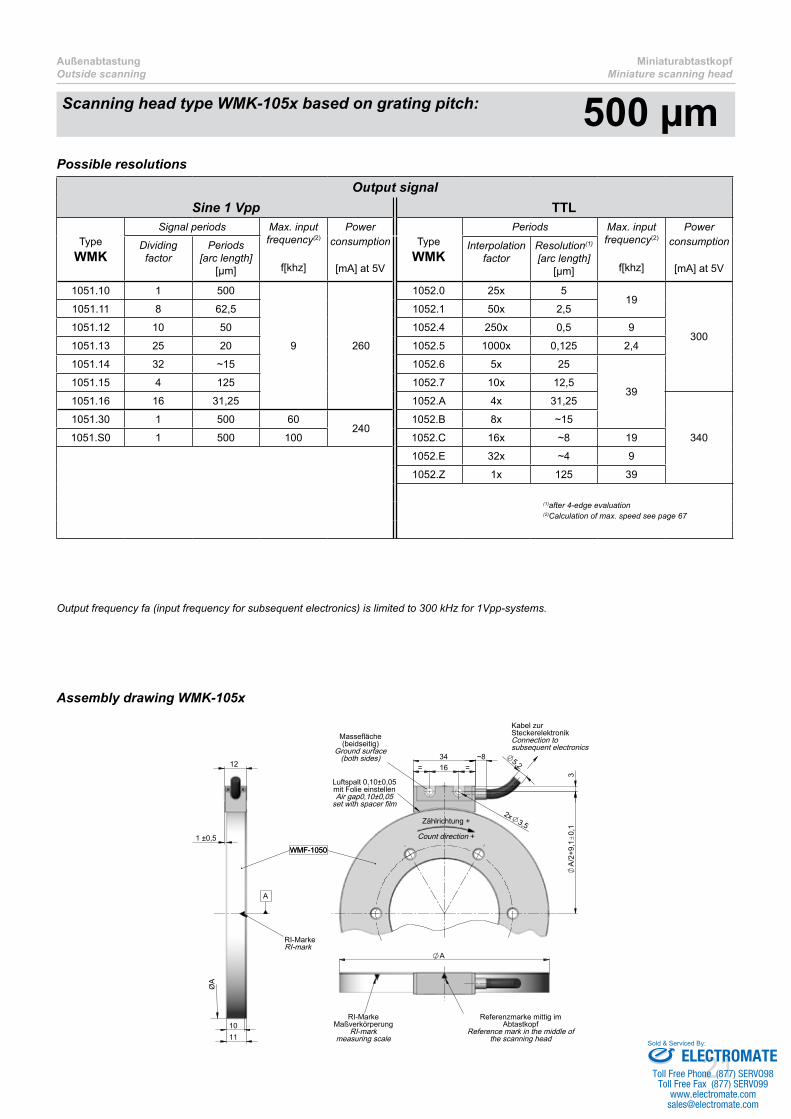
Outputfrequencyfa(inputfrequencyforsubsequentelectronics)islimitedto300kHzfor1Vpp-systems.
3
16= =34 5,2
~8
2x3,5
A/2
+9,1
0,1
Massefläche(beidseitig)
Ground surface(both sides)
Luftspalt 0,10±0,05mit Folie einstellenAir gap0,10±0,05
set with spacer film
Kabel zurSteckerelektronikConnection tosubsequent electronics
Zählrichtung +
Count direction +
RI-MarkeRI-mark
WMF-1050
A
A
RI-MarkeMaßverkörperung
RI-markmeasuring scale
Referenzmarke mittig im Abtastkopf
Reference mark in the middle of the scanning head
1 ±0,5
1011
12
WMF-1050
ØA
Assembly drawing WMK-105x
Possible resolutions
Scanning head type WMK-105x based on grating pitch: 500 µmOutput signal
Sine 1 Vpp TTL
TypeWMK
Signal periods Max. input frequency(2)
f[khz]
Powerconsumption
[mA] at 5V
TypeWMK
Periods Max. input frequency(2)
f[khz]
Powerconsumption
[mA] at 5V
Dividing factor
Periods[arc length]
[µm]
Interpolation factor
Resolution(1)
[arc length][µm]
1051.10 1 500
9 260
1052.0 25x 519
300
1051.11 8 62,5 1052.1 50x 2,5
1051.12 10 50 1052.4 250x 0,5 9
1051.13 25 20 1052.5 1000x 0,125 2,4
1051.14 32 ~15 1052.6 5x 25
391051.15 4 125 1052.7 10x 12,5
1051.16 16 31,25 1052.A 4x 31,25
340
1051.30 1 500 60240
1052.B 8x ~15
1051.S0 1 500 100 1052.C 16x ~8 19
1052.E 32x ~4 9
1052.Z 1x 125 39
(1)after 4-edge evaluation (2)Calculation of max. speed see page 67
ELECTROMATEToll Free Phone (877) SERVO98
Toll Free Fax (877) SERV099www.electromate.com
Sold & Serviced By:

22
MiniaturabtastkopfMiniature scanning head
AußenabtastungOutside scanning
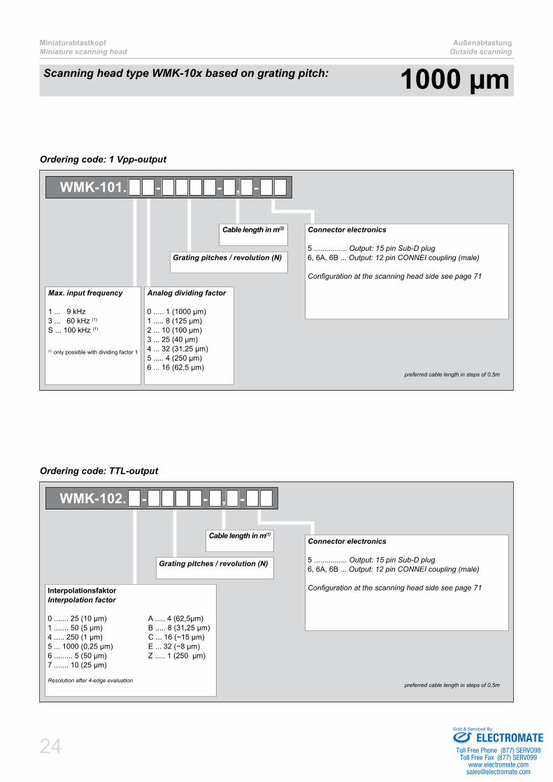
Ordering code: 1 Vpp-output
Bestellcode: TTL-Ausgang / Ordering code: TTL-output
Scanning head type WMK-105x based on grating pitch: 500 µm
Connector electronics
5 ................ Output: 15 pin Sub-D plug6, 6A, 6B ... Output: 12 pin CONNEI coupling (male)
Configurationatthescanningheadsideseepage71
Cable length in m(2)
Grating pitches / revolution (N)
Analog dividing factor
0 ..... 1 (500 µm)1 ..... 8 (62,5 µm)2 ... 10 (50 µm)3 ... 25 (20 µm)4 ... 32 (~15 µm)5 ..... 4 (125 µm)6 ... 16 (31,25 µm)
Max. input frequency
1 ..... 9 kHz3 ..... 60 kHz (1)
S ... 100 kHz (1)
(1) only possible with dividing factor 1
WMK-1051. - - , -
( preferred cable length in steps of 0,5m
Interpolation factor
0 ....... 25 (5 µm) A ..... 4 (31,25µm)1 ....... 50 (2,5 µm) B ..... 8 (~15 µm)4 ..... 250 (0,5 µm) C ... 16 (~8 µm)5 ... 1000 (0,125 µm) E ... 32 (~4 µm)6 ......... 5 (25 µm) Z ..... 1 (125 µm)7 ....... 10 (12,5 µm)
Resolution after 4-edge evaluation
Connector electronics
5 ................ Output: 15 pin Sub-D plug6, 6A, 6B ... Output: 12 pin CONNEI coupling (male)
Configurationatthescanningheadsideseepage71
Cable length in m(1)
Grating pitches / revolution (N)
WMK-1052. - - , -
preferred cable length in steps of 0,5m
ELECTROMATEToll Free Phone (877) SERVO98
Toll Free Fax (877) SERV099www.electromate.com
Sold & Serviced By:

23
AußenabtastungOutside scanning
MiniaturabtastkopfMiniature scanning head
12
1 ±0,5
11
10
WMF-100
0,1 A
3
16= =34 5,2
~8
2x3,5
A/2
+9,1
50,
1
Massefläche(beidseitig)
Ground surface(both sides)
Luftspalt 0,15±0,1mit Folie einstellen
Air gap0,15±0,1set with spacer film
Kabel zurSteckerelektronikConnection tosubsequent electronics
Zählrichtung +
Count direction +
A
RI-MarkeMaßverkörperung
RI-markmeasuring scale
Referenzmarke mittig im Abtastkopf
Reference mark in the middle of the scanning head
10
0,65
1 ±0,5
12
RI-MarkeRI-mark
WMR-100
ØA
0,1 A
A A
Possible resolutions
Assembly drawing WMK-10x
Output signalSine 1 Vpp TTL
Type
WMK
Signal periodsMax. input frequency(2)
f[khz]
Powerconsumption
[mA] at 5V
Type
WMK
Periods Max. input frequency(2)
f[khz]
Powerconsumption
[mA] at 5VDividing factor
Periods[arc length]
[µm]
Interpolation factor
Resolution(1)
[arc length][µm]
101.10 1 1000
9 260
102.0 25x 1019
300
101.11 8 125 102.1 50x 5
101.12 10 100 102.4 250x 1 9
101.13 25 40 102.5 1000x 0,25 2,4
101.14 32 31,25 102.6 5x 50
39101.15 4 250 102.7 10x 25
101.16 16 62,5 102.A 4x 62,5
340
101.30 1 1000 60240
102.B 8x 31,25
101.S0 1 1000 100 102.C 16x ~15 19
102.E 32x ~8 9
102.Z 1x 250 39
after 4-edge evaluation Calculation of max. speed see page 66
Outputfrequencyfa(inputfrequencyforsubsequentelectronics)islimitedto300kHzfor1Vpp-systems.
Scanning head type WMK-10x based on grating pitch: 1000 µm
ELECTROMATEToll Free Phone (877) SERVO98
Toll Free Fax (877) SERV099www.electromate.com
Sold & Serviced By:
24
MiniaturabtastkopfMiniature scanning head
AußenabtastungOutside scanning
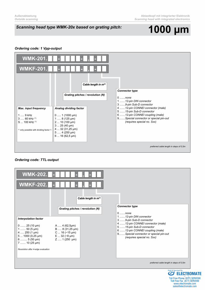
Ordering code: 1 Vpp-output
Ordering code: TTL-output
Scanning head type WMK-10x based on grating pitch: 1000 µm
Connector electronics
5 ................ Output: 15 pin Sub-D plug6, 6A, 6B ... Output: 12 pin CONNEI coupling (male)
Configurationatthescanningheadsideseepage71
Cable length in m(2)
Grating pitches / revolution (N)
Analog dividing factor
0 ..... 1 (1000 µm)1 ..... 8 (125 µm)2 ... 10 (100 µm)3 ... 25 (40 µm)4 ... 32 (31,25 µm)5 ..... 4 (250 µm)6 ... 16 (62,5 µm)
Max. input frequency
1 ... 9 kHz3 ... 60 kHz (1)
S ... 100 kHz (1)
(1) only possible with dividing factor 1
WMK-101. - - , -
preferred cable length in steps of 0,5m
InterpolationsfaktorInterpolation factor
0 ....... 25 (10 µm) A ..... 4 (62,5µm)1 ....... 50 (5 µm) B ..... 8 (31,25 µm)4 ..... 250 (1 µm) C ... 16 (~15 µm)5 ... 1000 (0,25 µm) E ... 32 (~8 µm)6 ......... 5 (50 µm) Z ..... 1 (250 µm)7 ....... 10 (25 µm)
Resolution after 4-edge evaluation
Connector electronics
5 ................ Output: 15 pin Sub-D plug6, 6A, 6B ... Output: 12 pin CONNEI coupling (male)
Configurationatthescanningheadsideseepage71
Cable length in m(1)
Grating pitches / revolution (N)
WMK-102. - - , -
preferred cable length in steps of 0,5m
ELECTROMATEToll Free Phone (877) SERVO98
Toll Free Fax (877) SERV099www.electromate.com
Sold & Serviced By:

25
Complete sensor and electro- ■nics integrated into the scan-ning headTwo head designs possible ■“high shape” (WMK-200) “flat shape” (WMKF-200)Can be combined with measu- ■ring flanges and measuring ringsProtection class IP67 ■Also available in ■ -design for explosion sensitive areas
Scanning head with integrated electronics for outside scanning
ELECTROMATEToll Free Phone (877) SERVO98
Toll Free Fax (877) SERV099www.electromate.com
Sold & Serviced By:

26
Abtastkopf mit integrierter ElektronikScanning head with integrated electronics
AußenabtastungOutside scanning
Technical data
Grating pitch [arc length]: 500 µm 1000 µm 3000 µmType: WMK-205x
WMKF-205xWMK-20x
WMKF-20xWMK-30x
WMKF-30xOperating temperature: -10°C … 100°C
Storage temperature: -20°C … 100°C
Protection class: IP67
Vibration: < 200 m/s² for 55 – 2000 Hz
Shock: < 2000 m/s² for 6 ms
Power supply: 5V ± 5%
Cable: Cablespecificationseepage72
Output signals: Sine 1Vpp or TTL (RS422); see diagram on page 71
System resolutions: [arc length]
Signal period 1Vpp: 500µm … ~15µm 1000µm … 31,25µm 3000µm … 93,75µm
Resolution TTL: 125µm … 0,125µm (1) 250µm … 0,25µm (1) 750µm … 0,75µm (1)
Detailed list of possible resolutions see on following pages.
Max. speed: See table on page 67
Suitable measuring scale: WMF-105xWMB-105x
see page 10
WMF-10xWMR-10x
see page 10
WMF-30xWMR-30x
see page 10
(1) ... after 4-edge evaluation
ELECTROMATEToll Free Phone (877) SERVO98
Toll Free Fax (877) SERV099www.electromate.com
Sold & Serviced By:

27
AußenabtastungOutside scanning
Abtastkopf mit integrierter ElektronikScanning head with integrated electronics
Possible resolutions
Output signalSine 1 Vpp TTL
Type
WMKWMKF
Signal periods Max. input frequency(2)
f[khz]
Powerconsumption
[mA] at 5V
Type
WMKWMKF
Periods Max. input frequency(2)
f[khz]
Powerconsumption
[mA] at 5V
Dividing factor
Periods[arc length]
[µm]
Interpolation factor
Resolution(1)
[arc length][µm]
2051.10 1 500
9 220
2052.0 25x 519
260
2051.11 8 62,5 2052.1 50x 2,5
2051.12 10 50 2052.4 250x 0,5 9
2051.13 25 20 2052.5 1000x 0,125 2,4
2051.14 32 ~15 2052.6 5x 25
392051.15 4 125 2052.7 10x 12,5
2051.16 16 31,25 2052.A 4x 31,25
300
2051.30 1 500 60200
2052.B 8x ~15
2051.S0 1 500 100 2052.C 16x ~8 19
2052.E 32x ~4 9
2052.Z 1x 125 39
(1) after 4-edge evaluation(2) Calculation of max. speed see page 67
Outputfrequencyfa(inputfrequencyforsubsequentelectronics)islimitedto300kHzfor1Vpp-systems.
Scanning head type WMK-205x based on grating pitch: 500 µm
ELECTROMATEToll Free Phone (877) SERVO98
Toll Free Fax (877) SERV099www.electromate.com
Sold & Serviced By:

28
Abtastkopf mit integrierter ElektronikScanning head with integrated electronics
AußenabtastungOutside scanning
Scanning head type WMK-205x based on grating pitch: 500 µmOrdering code: 1 Vpp-output
Ordering code: TTL-output
Cable length in m(2)
Grating pitches / revolution (N)
Analog dividing factor
0 ..... 1 (500 µm)1 ..... 8 (62,5 µm)2 ... 10 (50 µm)3 ... 25 (20 µm)4 ... 32 (~15 µm)5 ..... 4 (125 µm)6 ... 16 (31,25 µm)
Max. input frequency
1 ..... 9 kHz3 ..... 60 kHz (1)
S ... 100 kHz (1)
(1) nur mit Teilungsfaktor 1 möglich (1) only possible with dividing factor 1
WMK-2051. - - , -
WMKF-2051. - - , -
Connector type
0 .......none1 .......12-pin DIN connector3 .......9-pin Sub-D connector4 .......12-pin CONNEI connector (male)5 .......15-pin Sub-D connector6 .......12-pin CONNEI coupling (male)9........Special connector or special pin-out (requires special no. Sxx)
preferred cable length in steps of 0,5m
Interpolation factor
0 ....... 25 (5 µm) A ..... 4 (31,25µm)1 ....... 50 (2,5 µm) B ..... 8 (~15 µm)4 ..... 250 (0,5 µm) C ... 16 (~8 µm)5 ... 1000 (0,125 µm) E ... 32 (~4 µm)6 ......... 5 (25 µm) Z ..... 1 (125 µm)7 ....... 10 (12,5 µm)
Resolution after 4-edge evaluation
Cable length in m(1)
Grating pitches / revolution (N)
WMK-2052. - - , -
WMKF-2052. - - , -
Connector type
0 .......none1 .......12-pin DIN connector3 .......9-pin Sub-D connector4 .......12-pin CONNEI connector (male)5 .......15-pin Sub-D connector6 .......12-pin CONNEI coupling (male)9........Special connector or special pin-out (requires special no. Sxx)
preferred cable length in steps of 0,5m
ELECTROMATEToll Free Phone (877) SERVO98
Toll Free Fax (877) SERV099www.electromate.com
Sold & Serviced By:

29
AußenabtastungOutside scanning
Abtastkopf mit integrierter ElektronikScanning head with integrated electronics
A
RI-MarkeMaßverkörperung RI-markmeasuring scale
Referenzmarke mittig im Abtastkopf
Reference mark in the middle of the scanning head
25
16,6
1011
7,5 ±0,5
ØA
RI-MarkeRI-mark
WMF-1050
0,1 A
A
5,2496173
7
R2,25
2 12,5
A/2
+1,1
MasseflächeGround surface
Luftspalt 0,10±0,05mit Folie einstellenAir gap0,10±0,05
set with spacer film
WMF-1050
Count direction+
Zahlrichtung +
A
RI-MarkeMaßverkörperung
RI-markmeasuring scale
Referenzmarke mittig im Abtastkopf
Reference mark in the middle of the scanning head
496173
10
R2,25
3,5
5,2
22,5
A/2
+3,6
MasseflächeGround surface
Luftspalt 0,10±0,05mit Folie einstellenAir gap0,10±0,05
set with spacer film
Zählrichtung +
Count direction +
WMF-1050
3 ±0,5
16
29
1011
ØA
RI-MarkeRI-mark
WMF-1050
0,1 A
A
Assembly drawing WMK-205x
Assembly drawing WMKF-205x
Scanning head type WMK-205x based on grating pitch: 500 µm
ELECTROMATEToll Free Phone (877) SERVO98
Toll Free Fax (877) SERV099www.electromate.com
Sold & Serviced By:

30
Abtastkopf mit integrierter ElektronikScanning head with integrated electronics
AußenabtastungOutside scanning
Possible resolutions
Output signalSine 1 Vpp TTL
Type
WMKWMKF
Signal periods Max. input frequency(2)
f[khz]
Powerconsumption
[mA] at 5V
Type
WMKWMKF
Periods Max. input frequency(2)
f[khz]
Powerconsumption
[mA] at 5V
Dividing factor
Periods[arc length]
[µm]
Interpolation factor
Resolution(1)
[arc length][µm]
201.10 1 1000
9 220
202.0 25x 1019
260
201.11 8 125 202.1 50x 5
201.12 10 100 202.4 250x 1 9
201.13 25 40 202.5 1000x 0,25 2,4
201.14 32 31,25 202.6 5x 50
39201.15 4 250 202.7 10x 25
201.16 16 62,5 202.A 4x 62,5
300
201.30 1 1000 60200
202.B 8x 31,25
201.S0 1 1000 100 202.C 16x ~15 19
202.E 32x ~8 9
202.Z 1x 250 39
after 4-edge evaluation Calculation of max. speed see page 66
Outputfrequencyfa(inputfrequencyforsubsequentelectronics)islimitedto300kHzfor1Vpp-systems.
Scanning head type WMK-20x based on grating pitch: 1000 µm
ELECTROMATEToll Free Phone (877) SERVO98
Toll Free Fax (877) SERV099www.electromate.com
Sold & Serviced By:
31
AußenabtastungOutside scanning
Abtastkopf mit integrierter ElektronikScanning head with integrated electronics
Scanning head type WMK-20x based on grating pitch: 1000 µmOrdering code: 1 Vpp-output
Ordering code: TTL-output
Cable length in m(2)
Grating pitches / revolution (N)
Analog dividing factor
0 ..... 1 (1000 µm)1 ..... 8 (125 µm)2 ... 10 (100 µm)3 ... 25 (40 µm)4 ... 32 (31,25 µm)5 ..... 4 (250 µm)6 ... 16 (62,5 µm)
Max. input frequency
1 ..... 9 kHz3 ..... 60 kHz (1)
S ... 100 kHz (1)
(1) only possible with dividing factor 1
WMK-201. - - , -
WMKF-201. - - , -
Connector type
0 .......none1 .......12-pin DIN connector3 .......9-pin Sub-D connector4 .......12-pin CONNEI connector (male)5 .......15-pin Sub-D connector6 .......12-pin CONNEI coupling (male)9........Special connector or special pin-out (requires special no. Sxx)
preferred cable length in steps of 0,5m
Interpolation factor
0 ....... 25 (10 µm) A ..... 4 (62,5µm)1 ....... 50 (5 µm) B ..... 8 (31,25 µm)4 ..... 250 (1 µm) C ... 16 (~15 µm)5 ... 1000 (0,25 µm) E ... 32 (~8 µm)6 ......... 5 (50 µm) Z ..... 1 (250 µm)7 ....... 10 (25 µm)
Resolution after 4-edge evaluation
Cable length in m(1)
Grating pitches / revolution (N)
WMK-202. - - , -
WMKF-202. - - , -
Connector type
0 .......none1 .......12-pin DIN connector3 .......9-pin Sub-D connector4 .......12-pin CONNEI connector (male)5 .......15-pin Sub-D connector6 .......12-pin CONNEI coupling (male)9........Special connector or special pin-out (requires special no. Sxx)
preferred cable length in steps of 0,5m
ELECTROMATEToll Free Phone (877) SERVO98
Toll Free Fax (877) SERV099www.electromate.com
Sold & Serviced By:

32
Abtastkopf mit integrierter ElektronikScanning head with integrated electronics
AußenabtastungOutside scanning
13
10
11
3 ±0,5
WMF-100
RI-mark
0,1 A
496173 5,2
R2,25
10
3,5
A/2
+3,6
522
,5
MasseflächeGround surface
Luftspalt 0,15±0,1mit Folie einstellenAir gap 0,15±0,1
set with spacer film
Zahlrichtung +
Count direction+
A
RI-MarkeMaßverkörperung
RI-markmeasuring scale
Referenzmarke mittig im Abtastkopf
Reference mark in the middle of the scanning head
16
29
0.65
10
3 ±0,5
WMR-100
ØA
RI-Marke
0,1 A
AA
Assembly drawing WMK-20x
49
6173
72 R2,25
5,2
12,5
A/2
+1,1
5
Luftspalt 0,15±0,1 mit folie einstellen Air gap 0,15±0,1set with spacer film
MasseflächeGround surface
25
(17,5)
10
11
7,5 ±0,5
WMF-100
RI-MarkeRI-mark
0,1 A
A
A
RI-MarkeMaßverkörperung RI-mark measuring scale
Referenzmarke mittig im Abtastkopf
Reference mark in the middle of the scanning head
7,5 ±0,5
25
0,65
10
ØA
RI-Marke
RI-mark
WMR-100
A
Assembly drawing WMKF-20x
Scanning head type WMK-20x based on grating pitch: 1000 µm
ELECTROMATEToll Free Phone (877) SERVO98
Toll Free Fax (877) SERV099www.electromate.com
Sold & Serviced By:

33
AußenabtastungOutside scanning
Abtastkopf mit integrierter ElektronikScanning head with integrated electronics
Possible resolutions
Output signalSine 1 Vpp TTL
Type
WMKWMKF
Signal periods Max. input frequency(2)
f[khz]
Powerconsumption
[mA] at 5V
Type
WMKWMKF
PeriodsMax. input frequency(2)
f[khz]
Powerconsumption
[mA] at 5V
Dividing factor
Periods[arc length]
[µm]
Interpolation factor
Resolution(1)
[arc length][µm]
301.10 1 3000
9 220
302.0 25x 3019
260
301.11 8 375 302.1 50x 15
301.12 10 300 302.4 250x 3 9
301.13 25 120 302.5 1000x 0,75 2,4
301.14 32 93,75 302.6 5x 150
39301.15 4 750 302.7 10x 75
301.16 16 187,5 302.A 4x 187,5
300
301.30 1 3000 60200
302.B 8x 93,75
301.S0 1 3000 100 302.C 16x ~47 19
302.E 32x ~23 9
302.Z 1x 750 39
after 4-edge evaluation Calculation of max. speed see page 66
Outputfrequencyfa(inputfrequencyforsubsequentelectronics)islimitedto300kHzfor1Vpp-systems.
Scanning head type WMK-30x based on grating pitch: 3000 µm
ELECTROMATEToll Free Phone (877) SERVO98
Toll Free Fax (877) SERV099www.electromate.com
Sold & Serviced By:
34
Abtastkopf mit integrierter ElektronikScanning head with integrated electronics
AußenabtastungOutside scanning
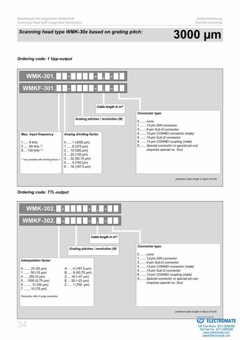
Ordering code: 1 Vpp-output
Scanning head type WMK-30x based on grating pitch: 3000 µm
Ordering code: TTL-output
Cable length in m(2)
Grating pitches / revolution (N)
Analog dividing factor
0 ..... 1 (3000 µm)1 ..... 8 (375 µm)2 ... 10 (300 µm)3 ... 25 (120 µm)4 ... 32 (93,75 µm)5 ..... 4 (750 µm)6 ... 16 (187,5 µm)
Max. input frequency
1 ..... 9 kHz3 ..... 60 kHz (1)
S ... 100 kHz (1)
(1) only possible with dividing factor 1
WMK-301. - - , -
WMKF-301. - - , -
Connector type
0 .......none1 .......12-pin DIN connector3 .......9-pin Sub-D connector4 .......12-pin CONNEI connector (male)5 .......15-pin Sub-D connector6 .......12-pin CONNEI coupling (male)9........Special connector or special pin-out (requires special no. Sxx)
preferred cable length in steps of 0,5m
Interpolation factor
0 ....... 25 (30 µm) A ..... 4 (187,5 µm)1 ....... 50 (15 µm) B ..... 8 (93,75 µm)4 ..... 250 (3 µm) C ... 16 (~47 µm)5 ... 1000 (0,75 µm) E ... 32 (~23 µm)6 ......... 5 (150 µm) Z ..... 1 (750 µm)7 ....... 10 (75 µm)
Resolution after 4-edge evaluation
Cable length in m(1)
Grating pitches / revolution (N)
WMK-302. - - , -
WMKF-302. - - , -
Connector type
0 .......none1 .......12-pin DIN connector3 .......9-pin Sub-D connector4 .......12-pin CONNEI connector (male)5 .......15-pin Sub-D connector6 .......12-pin CONNEI coupling (male)9........Special connector or special pin-out (requires special no. Sxx)
preferred cable length in steps of 0,5m
ELECTROMATEToll Free Phone (877) SERVO98
Toll Free Fax (877) SERV099www.electromate.com
Sold & Serviced By:

35
AußenabtastungOutside scanning
Abtastkopf mit integrierter ElektronikScanning head with integrated electronics
496173
10
22.5
A/2
+3,9
5,2
3,5R2,25
RI-MarkeRI-mark
MasseflächeGround surface
Luftspalt 0,40±0,2mit Folie einstellenAir gap 0,40±0,2
set with spacer film
Count direction+
Zahlrichtung +
A
16
0,65
14
1 ±1
ØA
WMR-300
0,1 A
A
RI-MarkeMaßverkörperung
RI-markmeasuring scale
Referenzmarke mittig im Abtastkopf
Reference mark in the middle of the scanning head
496173
R2,25
27
5,2
13,5
A/2
+1,4
Luftspalt 0,40±0,2mit Folie einstellenAir gap 0,40±0,2
set with spacer film
MasseflächeGround surface
Count direction+
Zahlrichtung +
25
14
0,65
5,5 ±1
ØA RI-Marke
RI-mark
WMR-300
0,1 A
A
A
RI-MarkeMaßverkörperung
RI-markmeasuring scale
Referenzmarke mittig im Abtastkopf
Reference mark in the middle of the scanning head
Assembly drawing WMK-30x
Assembly drawing WMKF-30x
Scanning head type WMK-30x based on grating pitch: 3000 µm
ELECTROMATEToll Free Phone (877) SERVO98
Toll Free Fax (877) SERV099www.electromate.com
Sold & Serviced By:

36 ELECTROMATEToll Free Phone (877) SERVO98
Toll Free Fax (877) SERV099www.electromate.com
Sold & Serviced By:

37
Grating pitches 500 µm, ■1000 µm, 3000 µmCan be combined with all ■scanning headsArbitrary size in diameter ■Easy mounting over snap ■effectNo magnetic components, ■no Hysteresis
Measuring rings for inside scanning
ELECTROMATEToll Free Phone (877) SERVO98
Toll Free Fax (877) SERV099www.electromate.com
Sold & Serviced By:

38
MessringeMeasuring rings
InnenabtastungInside scanning
Measuring rings for inside scanning
Designed to be mounted over a “snap-effect” by the customer into a corresponding groove or against a stop collar (see mounting instruction at www.amo-gmbh.com).Forspecialapplications,inagreementwiththecustomer,themeasuringring(circularsegmentsalsopossible)canbemountedonaflangeatthefactory.
Grating pitch [arc length]: 500 µm 1000 µm 3000 µm
Type: WMR-115x WMR-11x WMR-31x
Grating accuracy [arc length]: ± 10 µm, ± 5 µm oder (or) ± 3 µm ± 20 µm, ± 10 µm oder (or) ± 5 µm
Mechanical execution: Stainless steel measuring ring
Flange material: 1.4104 oder (or)1.7225 (42CrMo4)1)
No special material required
Reference mark: 1 mark / 360° as standard or any desired number and position or distance coded (see page 68)
Standard sizes N: 1024, 1440,1800, 2048
0512, 0720, 0900,1024, 1440, 2048
0170, 0240, 0256, 03000341, 0360, 0480, 0512
N … Grating pitches per revolution
1) Please contact AMO if using other soft magnetic material
B
14
0,60
AußendurchmesserOuter diameter
B
10
0,60 (WMR-11x mit Trägerband)0,20 (WMR-115x ohne Trägerband)
WMR-11x
AußendurchmesserOuter diameter
WMR-115x / WMR-11x WMR-31x
Technical data
ELECTROMATEToll Free Phone (877) SERVO98
Toll Free Fax (877) SERV099www.electromate.com
Sold & Serviced By:

39
InnenabtastungInside scanning
MessringeMeasuring rings
Mechanical design for WMR-115x
WMR-115x
10,01 0+0,1
0,8 0,8
0,5
ØB
ØS
= Ø
B -0
,35 ±
0,05
GratfreiBurr freeGratfreiBurr free
3,20,02 A
0,005* A
0,02 A
A
Ø
S L
änge
>16
mm
Frei
raum
für A
btas
tkop
f k
eep
free
for >
16m
m M
easu
ring
head
wid
th
Recommended material: 1.4104 oder (or) 1.7225 (42CrMo4)Please contact AMO if using other soft magnetic material.
Grating pitch [arc length]: 500 µmN ØB [mm]
1024 bis (to) 1439 N/2π + 0,13 ±0,01
1440 bis (to) 2049 N/2π + 0,07 ±0,02
2050 bis (to) 3000 N/2π + 0,04 ±0,03
3001 bis (to) 4000 N/2π + 0,00 ±0,06
4001 bis (to) 6000 N/2π - 0,03 ±0,07
06001 bis (to) 10000 N/2π - 0,06 ±0,10
N: Integer number of grating pitches per revolution
*) Recommended eccentricity: Greater eccentricities up to ~0,03mm do not affect the function of the device, but cause a proportional loss in positioning accuracy.
Mechanical design for WMR-11x
WMR-11x
10,01 0+0,1
0,8 0,8
0,5
ØB
ØS
= Ø
B -1
,15 ±
0,05
GratfreiBurr freeGratfreiBurr free
3,2 0,02 A
0,005* A
0,02 A
A
Ø
S L
änge
>16
mm
Frei
raum
für A
btas
tkop
f k
eep
free
for >
16m
m M
easu
ring
head
wid
th
Grating pitch [arc length]: 1000 µmN ØB [mm]
512 bis (to) 719 N/π + 0,73 ±0,01
0720 bis (to) 1024 N/π + 0,67 ±0,02
1025 bis (to) 1500 N/π + 0,64 ±0,03
1501 bis (to) 2000 N/π + 0,60 ±0,06
2001 bis (to) 3000 N/π + 0,57 ±0,07
3001 bis (to) 8000 N/π + 0,54 ±0,10
N: Integer number of grating pitches per revolution
*) Recommended eccentricity: Greater eccentricities up to ~0,05mm do not affect the function of the device, but cause a proportional loss in positioning accuracy.
ELECTROMATEToll Free Phone (877) SERVO98
Toll Free Fax (877) SERV099www.electromate.com
Sold & Serviced By:

40
MessringeMeasuring rings
InnenabtastungInside scanning
Ordering code: WMR-31x
Mechanical design for WMR-31x
WMR-31x
14,01 0+0,1
0,5
0,8 0,8
ØB
ØS
= Ø
B -
1,15
±0,0
5
GratfreiBurr freeGratfreiBurr free
3,2
0,02 A
0,005* A
0,02 A
A Ø
S L
änge
>18
mm
Frei
raum
für A
btas
tkop
f k
eep
free
for >
18m
m M
easu
ring
head
wid
th
Grating pitch [arc length]: 3000 µmN ØB [mm]
170 bis (to) 240 Nx3/π + 0,73 ±0,01
241 bis (to) 342 Nx3/π + 0,67 ±0,02
343 bis (to) 500 Nx3/π + 0,64 ±0,03
501 bis (to) 830 Nx3/π + 0,60 ±0.05
0831 bis (to) 1330 Nx3/π + 0,57 ±0,07
01331 bis (to) 1830 Nx3/π + 0,54 ±0,10
N: Integer number of grating pitches per revolution
*) Recommended eccentricity: Greater eccentricities up to ~0,10mm do not affect the function of the device, but cause a proportional loss in positioning accuracy.
TheprocuctiondrawingforthecarrierflangecanbereleasedbyAMO.Forapplicationswithlargediametersorsignificantvariationsintemperatureduringoperationandwhenthecarrierflangesarenotmadeofsteel,the system must be designed accordingly.
Grating pitches / revolution (N)
RI - Position
00 ........ none01 ........ 1 RI / revolutionKxx ...... Distance-coded (basic spacing xx grating pitches)
Grating accuracy
0 ... ± 20 µm arc length 1 ... ± 10 µm arc length 2 ... ± 5 µm arc length
WMR-31 - -
Ordering code: WMR-115x / WMR-11x
Grating pitches / revolution (N)
RI - Position
00 ........ none01 ........ 1 RI / revolutionKxx ...... Distance-coded (basic spacing xx grating pitches)
Grating accuracy
0 ... ± 10 µm arc length 1 ... ± 5 µm arc length 2 ... ± 3 µm arc length
WMR-11 - -
WMR-115 - -
ELECTROMATEToll Free Phone (877) SERVO98
Toll Free Fax (877) SERV099www.electromate.com
Sold & Serviced By:

41
Scanning head for small ■designElectronic integrated in ■connectorCan be combined with ■measuring ringsProtection class IP67 ■
Miniature scanning head for inside scanning
ELECTROMATEToll Free Phone (877) SERVO98
Toll Free Fax (877) SERV099www.electromate.com
Sold & Serviced By:

42
MiniaturabtastkopfMiniature scanning head
InnenabtastungInside scanning
Technical data
Grating pitch [arc length]: 500 µm 1000 µmType: WMK-115x WMK-11x
Operating temperature: -10°C … 100°C
Storage temperature: -20°C … 100°C
Protection class: Scanning head: IP67
Connector electronics with Connei connector: IP67
Connector electronics with Sub-D connector: IP54
Vibration: < 400 m/s² for 55 – 2000 Hz
Shock: < 2000 m/s² for 6 ms
Power supply: 5V ± 5%
Cable: Cablespecificationseepage70
Output signals: Sine 1Vpp or TTL (RS422); see diagram on page 69
System resolutions: [arc length]
Signal period 1Vpp: 500µm … ~15µm 1000µm … 31,25µm
Resolution TTL: 125µm … 0,125µm (1) 250µm … 0,25µm (1)
Detailed list of possible resolutions see on following pages.
Max. speed: See table on page 66
Suitable measuring scale: WMR-115x
see page 37
WMR-11x
see page 37
(1) ... after 4-edge evaluation
ELECTROMATEToll Free Phone (877) SERVO98
Toll Free Fax (877) SERV099www.electromate.com
Sold & Serviced By:

43
InnenabtastungInside scanning
MiniaturabtastkopfMiniature scanning head
Assembly drawing WMK-115x
Possible resolutions
A
WMR-1150
Lufts
palt
mit
folie
ein
stel
len
Air
gap
set w
ith s
pace
r film
MasseflächeGround surface
RI-SeiteRI-side
Count direction
Zählrichtung
+
Ø5,2
0,1 A 113
10 1±0.5
0
,10
0,05
12
14
3,5
~8 34
16
Output signalSine 1 Vpp TTL
Type
WMK
Signal periods Max. input frequency(2)
f[khz]
Powerconsumption
[mA] at 5V
Type
WMK
Periods Max. input frequency(2)
f[khz]
Powerconsumption
[mA] at 5V
Dividing factor
Periods[arc length]
[µm]
Interpolation factor
Resolution(1)
[arc length]
[µm]
1151.10 1 500
9 260
1152.0 25x 519
300
1151.11 8 62,5 1152.1 50x 2,5
1151.12 10 50 1152.4 250x 0,5 9
1151.13 25 20 1152.5 1000x 0,125 2,4
1151.14 32 ~15 1152.6 5x 25
391151.15 4 125 1152.7 10x 12,5
1151.16 16 31,25 1152.A 4x 31,25
340
1151.30 1 500 60240
1152.B 8x ~15
1151.S0 1 500 100 1152.C 16x ~8 19
1152.E 32x ~4 9
1152.Z 1x 125 39
(1) after 4-edge evaluation(2) Calculation of max. speed see page 66
Outputfrequencyfa(inputfrequencyforsubsequentelectronics)islimitedto300kHzfor1Vpp-systems.
Scanning head type WMK-115x based on grating pitch: 500 µm
ELECTROMATEToll Free Phone (877) SERVO98
Toll Free Fax (877) SERV099www.electromate.com
Sold & Serviced By:

44
MiniaturabtastkopfMiniature scanning head
InnenabtastungInside scanning
Scanning head type WMK-115x based on grating pitch: 500 µm
Ordering code: 1 Vpp-output
Ordering code: TTL-output
Connector electronics
5 ................ Output: 15 pin Sub-D plug6, 6A, 6B ... Output: 12 pin CONNEI coupling (male)
Configurationatthescanningheadsideseepage71
Cable length in m(2)
Grating pitches / revolution (N)
Analog dividing factor
0 ..... 1 (500 µm)1 ..... 8 (62,5 µm)2 ... 10 (50 µm)3 ... 25 (20 µm)4 ... 32 (~15 µm)5 ..... 4 (125 µm)6 ... 16 (31,25 µm)
Max. input frequency
1 ..... 9 kHz3 ..... 60 kHz (1)
S ... 100 kHz (1)
(1) nur mit Teilungsfaktor 1 möglich (1) only possible with dividing factor 1
WMK-1151. - - , -
preferred cable length in steps of 0,5m
Interpolation factor
0 ....... 25 (5 µm) A ..... 4 (31,25µm)1 ....... 50 (2,5 µm) B ..... 8 (~15 µm)4 ..... 250 (0,5 µm) C ... 16 (~8 µm)5 ... 1000 (0,125 µm) E ... 32 (~4 µm)6 ......... 5 (25 µm) Z ..... 1 (125 µm)7 ....... 10 (12,5 µm)
Resolution after 4-edge evaluation
Connector electronics
5 ................ Ausgang: 15 pol. Sub-D Stecker Output: 15 pin Sub-D plug6, 6A, 6B ... Ausgang: 12 pol. CONNEI Kupplung (Stift) Output: 12 pin CONNEI coupling (male)
Ausführung abtastkopfseitig siehe Zeichnungen auf Seite 71Configurationatthescanningheadsideseepage71
Cable length in m(1)
Grating pitches / revolution (N)
WMK-1152. - - , -
preferred cable length in steps of 0,5m
ELECTROMATEToll Free Phone (877) SERVO98
Toll Free Fax (877) SERV099www.electromate.com
Sold & Serviced By:

45
InnenabtastungInside scanning
MiniaturabtastkopfMiniature scanning head
A
WMR-110
Lufts
palt
mit
folie
ein
stel
len
Air
gap
set w
ith s
pace
r film
MasseflächeGround surface
RI-SeiteRI-side
Count direction
Zählrichtung
+
Ø5,2
0,1 A 113
10 1±0.5
0
,15±
0.1
12
14
3,5
~8 34
16
Possible resolutions
Assembly drawing WMK-11x
Output signalSine 1 Vpp TTL
Type
WMK
Signal periods Max. input frequency(2)
f[khz]
Powerconsumption
[mA] at 5V
Type
WMK
Periods Max. input frequency(2)
f[khz]
Powerconsumption
[mA] at 5V
Dividing factor
Periods[arc length]
[µm]
Interpolation factor
Resolution(1)
[arc length][µm]
111.10 1 1000
9 260
112.0 25x 1019
300
111.11 8 125 112.1 50x 5
111.12 10 100 112.4 250x 1 9
111.13 25 40 112.5 1000x 0,25 2,4
111.14 32 31,25 112.6 5x 50
39111.15 4 250 112.7 10x 25
111.16 16 62,5 112.A 4x 62,5
340
111.30 1 1000 60240
112.B 8x 31,25
111.S0 1 1000 100 112.C 16x ~15 19
112.E 32x ~8 9
112.Z 1x 250 39
( after 4-edge evaluation Calculation of max. speed see page 66
Outputfrequencyfa(inputfrequencyforsubsequentelectronics)islimitedto300kHzfor1Vpp-systems.
Scanning head type WMK-11x based on grating pitch: 1000 µm
ELECTROMATEToll Free Phone (877) SERVO98
Toll Free Fax (877) SERV099www.electromate.com
Sold & Serviced By:

46
MiniaturabtastkopfMiniature scanning head
InnenabtastungInside scanning
Scanning head type WMK-11x based on grating pitch: 1000 µm
Ordering code: 1 Vpp-output
Ordering code: TTL-output
Connector electronics
5 ................ Output: 15 pin Sub-D plug6, 6A, 6B ... Output: 12 pin CONNEI coupling (male)
Configurationatthescanningheadsideseepage71
Cable length in m(2)
Grating pitches / revolution (N)
Analog dividing factor
0 ..... 1 (1000 µm)1 ..... 8 (125 µm)2 ... 10 (100 µm)3 ... 25 (40 µm)4 ... 32 (31,25 µm)5 ..... 4 (250 µm)6 ... 16 (62,5 µm)
Max. input frequency
1 ... 9 kHz3 ... 60 kHz (1)
S ... 100 kHz (1)
(1) nur mit Teilungsfaktor 1 möglich (1) only possible with dividing factor 1
WMK-111. - - , -
preferred cable length in steps of 0,5m
Interpolation factor
0 ....... 25 (10 µm) A ..... 4 (62,5µm)1 ....... 50 (5 µm) B ..... 8 (31,25 µm)4 ..... 250 (1 µm) C ... 16 (~15 µm)5 ... 1000 (0,25 µm) E ... 32 (~8 µm)6 ......... 5 (50 µm) Z ..... 1 (250 µm)7 ....... 10 (25 µm)
Resolution after 4-edge evaluation
Connector electronics
5 ................ Output: 15 pin Sub-D plug6, 6A, 6B ... Output: 12 pin CONNEI coupling (male)
Configurationatthescanningheadsideseepage71
Cable length in m(1)
Grating pitches / revolution (N)
WMK-112. - - , -
preferred cable length in steps of 0,5m
ELECTROMATEToll Free Phone (877) SERVO98
Toll Free Fax (877) SERV099www.electromate.com
Sold & Serviced By:

47
Complete sensor and elec- ■tronics integrated into the scanning headProtection class IP67 ■Can be combined with ■measuring ringsA ■ lso available in -design for explosion sensitive areas
Scanning head with integrated electronics for inside scanning
ELECTROMATEToll Free Phone (877) SERVO98
Toll Free Fax (877) SERV099www.electromate.com
Sold & Serviced By:

48
Abtastkopf mit integrierter ElektronikScanning head with integrated electronics
InnenabtastungInside scanning
Technical data
Grating pitch [arc length]: 500 µm 1000 µm 3000 µmType: WMK-215x WMK-21x WMK-31x
Operating temperature: -10°C … 100°C
Storage temperature: -20°C … 100°C
Protection class: IP67
Vibration: < 200 m/s² for 55 – 2000 Hz
Shock: < 2000 m/s² for 6 ms
Power supply: 5V ± 5%
Cable: Cablespecificationseepage70
Output signals: Sine 1Vpp or TTL (RS422); see diagram on page 69
System resolutions: [arc length]
Signal period 1Vpp: 500µm … ~15µm 1000µm … 31,25µm 3000µm … 93,75µm
Resolution TTL: 125µm … 0,125µm (1) 250µm … 0,25µm (1) 750µm … 0,75µm (1)
Detailed list of possible resolutions see on following pages.
Max. speed: See table on page 68
Suitable measuring scale: WMR-115x
see page 37
WMR-11x
see page 37
WMR-31x
see page 37(1) ... after 4-edge evaluation
ELECTROMATEToll Free Phone (877) SERVO98
Toll Free Fax (877) SERV099www.electromate.com
Sold & Serviced By:

49
InnenabtastungInside scanning
Abtastkopf mit integrierter ElektronikScanning head with integrated electronics
Assembly drawing WMK-215x
Possible resolutions
5,2
+
Lufts
palt
mit
Folie
ein
stel
len
Air g
ap s
et w
ith s
pace
r film
Zählrichtung
Count direction
MasseflächeGround surface
RI-SeiteRI-side
A
WMR-115xWMR-115x
0,1 A
73
61
10
0
,10±
0.05
3 ±0,5
31
16
3,5
R2,5
14,5
16,5
Output signalSine 1 Vpp TTL
Type
WMK
Signal periods Max. input frequency(2)
f[khz]
Powerconsumption
[mA] at 5V
Type
WMK
Periods Max. input frequency(2)
f[khz]
Powerconsumption
[mA] at 5V
Dividing factor
Periods[arc length]
[µm]
Interpolation factor
Resolution(1)
[arc length][µm]
2151.10 1 500
9 220
2152.0 25x 519
260
2151.11 8 62,5 2152.1 50x 2,5
2151.12 10 50 2152.4 250x 0,5 9
2151.13 25 20 2152.5 1000x 0,125 2,4
2151.14 32 ~15 2152.6 5x 25
392151.15 4 125 2152.7 10x 12,5
2151.16 16 31,25 2152.A 4x 31,25
300
2151.30 1 500 60200
2152.B 8x ~15
2151.S0 1 500 100 2152.C 16x ~8 19
2152.E 32x ~4 9
2152.Z 1x 125 39
after 4-edge evaluation Calculation of max. speed see page 66
Outputfrequencyfa(inputfrequencyforsubsequentelectronics)islimitedto300kHzfor1Vpp-systems.
Scanning head type WMK-215x based on grating pitch: 500 µm
ELECTROMATEToll Free Phone (877) SERVO98
Toll Free Fax (877) SERV099www.electromate.com
Sold & Serviced By:
50
Abtastkopf mit integrierter ElektronikScanning head with integrated electronics
InnenabtastungInside scanning
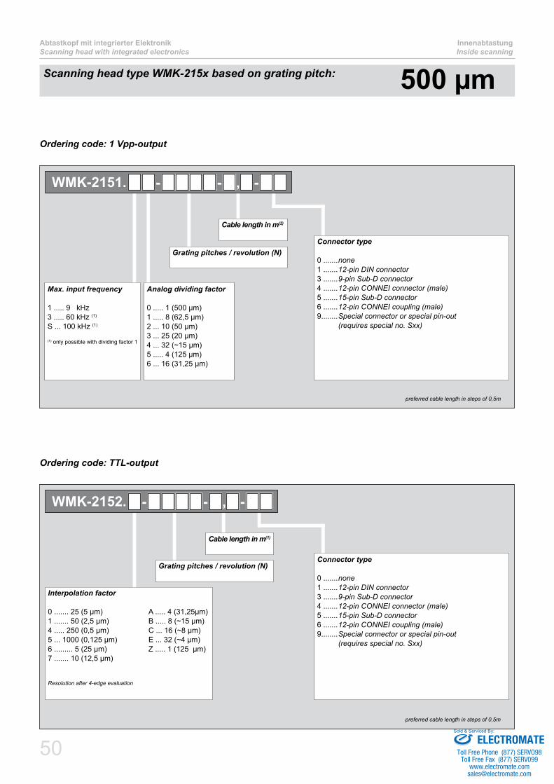
Scanning head type WMK-215x based on grating pitch: 500 µm
Ordering code: 1 Vpp-output
Ordering code: TTL-output
Cable length in m(2)
Grating pitches / revolution (N)
Analog dividing factor
0 ..... 1 (500 µm)1 ..... 8 (62,5 µm)2 ... 10 (50 µm)3 ... 25 (20 µm)4 ... 32 (~15 µm)5 ..... 4 (125 µm)6 ... 16 (31,25 µm)
Max. input frequency
1 ..... 9 kHz3 ..... 60 kHz (1)
S ... 100 kHz (1)
(1) only possible with dividing factor 1
WMK-2151. - - , -
Connector type
0 .......none1 .......12-pin DIN connector3 .......9-pin Sub-D connector4 .......12-pin CONNEI connector (male)5 .......15-pin Sub-D connector6 .......12-pin CONNEI coupling (male)9........Special connector or special pin-out (requires special no. Sxx)
preferred cable length in steps of 0,5m
Interpolation factor
0 ....... 25 (5 µm) A ..... 4 (31,25µm)1 ....... 50 (2,5 µm) B ..... 8 (~15 µm)4 ..... 250 (0,5 µm) C ... 16 (~8 µm)5 ... 1000 (0,125 µm) E ... 32 (~4 µm)6 ......... 5 (25 µm) Z ..... 1 (125 µm)7 ....... 10 (12,5 µm)
Resolution after 4-edge evaluation
Cable length in m(1)
Grating pitches / revolution (N)
WMK-2152. - - , -
Connector type
0 .......none1 .......12-pin DIN connector3 .......9-pin Sub-D connector4 .......12-pin CONNEI connector (male)5 .......15-pin Sub-D connector6 .......12-pin CONNEI coupling (male)9........Special connector or special pin-out (requires special no. Sxx)
preferred cable length in steps of 0,5m
ELECTROMATEToll Free Phone (877) SERVO98
Toll Free Fax (877) SERV099www.electromate.com
Sold & Serviced By:

51
InnenabtastungInside scanning
Abtastkopf mit integrierter ElektronikScanning head with integrated electronics
Possible resolutions
Assembly drawing WMK-21x
5,2A
Lufts
palt
mit
Folie
ein
stel
len
Air g
ap s
et w
ith s
pace
r film
MasseflächeGround surface
Count direction
Zählrichtung
+
RI-SeiteRI-side
WMR-110WMR-110
0,1 A
73
61
10
0,1
5±0.
1
3 ±0,5
31
16
3,5
R2,5
14,5
16,5
Output signalSine 1 Vpp TTL
Type
WMK
Signal periods Max. input frequency(2)
f[khz]
Powerconsumption
[mA] at 5V
Type
WMK
Periods Max. input frequency(2)
f[khz]
Powerconsumption
[mA] at 5V
Dividing factor
Periods[arc length]
[µm]
Interpolation factor
Resolution(1)
[arc length]
[µm]
211.10 1 1000
9 220
212.0 25x 1019
260
211.11 8 125 212.1 50x 5
211.12 10 100 212.4 250x 1 9
211.13 25 40 212.5 1000x 0,25 2,4
211.14 32 31,25 212.6 5x 50
39211.15 4 250 212.7 10x 25
211.16 16 62,5 212.A 4x 62,5
300
211.30 1 1000 60200
212.B 8x 31,25
211.S0 1 1000 100 212.C 16x ~15 19
212.E 32x ~8 9
212.Z 1x 250 39
after 4-edge evaluation Calculation of max. speed see page 66
Outputfrequencyfa(inputfrequencyforsubsequentelectronics)islimitedto300kHzfor1Vpp-systems.
Scanning head type WMK-21x based on grating pitch: 1000 µm
ELECTROMATEToll Free Phone (877) SERVO98
Toll Free Fax (877) SERV099www.electromate.com
Sold & Serviced By:
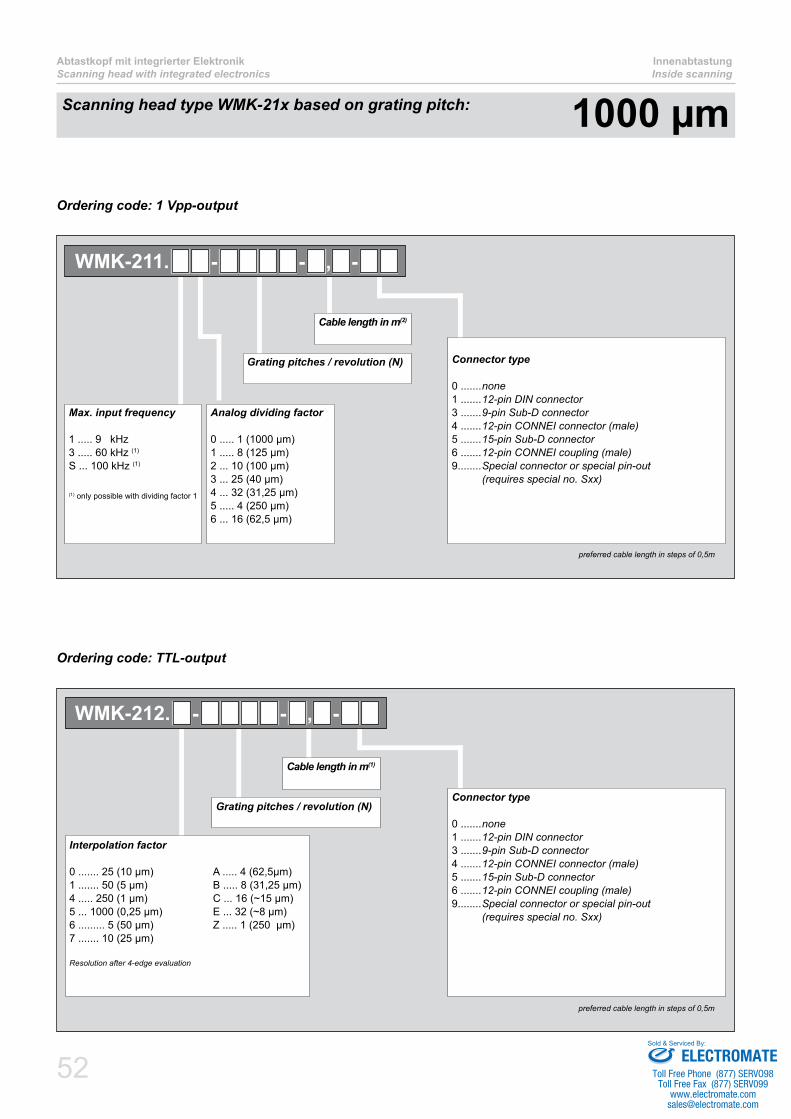
52
Abtastkopf mit integrierter ElektronikScanning head with integrated electronics
InnenabtastungInside scanning
Scanning head type WMK-21x based on grating pitch: 1000 µm
Ordering code: 1 Vpp-output
Ordering code: TTL-output
Cable length in m(2)
Grating pitches / revolution (N)
Analog dividing factor
0 ..... 1 (1000 µm)1 ..... 8 (125 µm)2 ... 10 (100 µm)3 ... 25 (40 µm)4 ... 32 (31,25 µm)5 ..... 4 (250 µm)6 ... 16 (62,5 µm)
Max. input frequency
1 ..... 9 kHz3 ..... 60 kHz (1)
S ... 100 kHz (1)
(1) only possible with dividing factor 1
WMK-211. - - , -
Connector type
0 .......none1 .......12-pin DIN connector3 .......9-pin Sub-D connector4 .......12-pin CONNEI connector (male)5 .......15-pin Sub-D connector6 .......12-pin CONNEI coupling (male)9........Special connector or special pin-out (requires special no. Sxx)
preferred cable length in steps of 0,5m
Interpolation factor
0 ....... 25 (10 µm) A ..... 4 (62,5µm)1 ....... 50 (5 µm) B ..... 8 (31,25 µm)4 ..... 250 (1 µm) C ... 16 (~15 µm)5 ... 1000 (0,25 µm) E ... 32 (~8 µm)6 ......... 5 (50 µm) Z ..... 1 (250 µm)7 ....... 10 (25 µm)
Resolution after 4-edge evaluation
Cable length in m(1)
Grating pitches / revolution (N)
WMK-212. - - , -
Connector type
0 .......none1 .......12-pin DIN connector3 .......9-pin Sub-D connector4 .......12-pin CONNEI connector (male)5 .......15-pin Sub-D connector6 .......12-pin CONNEI coupling (male)9........Special connector or special pin-out (requires special no. Sxx)
preferred cable length in steps of 0,5m
ELECTROMATEToll Free Phone (877) SERVO98
Toll Free Fax (877) SERV099www.electromate.com
Sold & Serviced By:
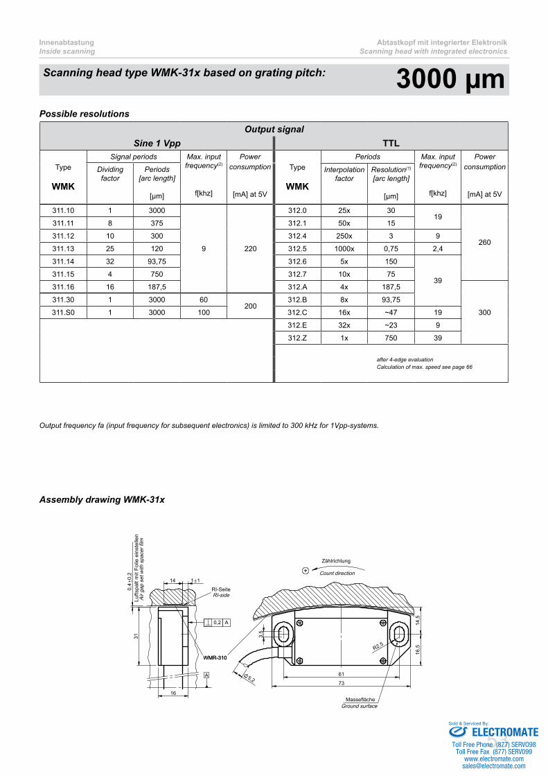
53
InnenabtastungInside scanning
Abtastkopf mit integrierter ElektronikScanning head with integrated electronics
Possible resolutions
Assembly drawing WMK-31x
5,2
14 1 1
+
Lufts
palt
mit
Folie
ein
stel
len
Air g
ap s
et w
ith s
pace
r film
Zählrichtung
Count direction
MasseflächeGround surface
RI-SeiteRI-side
A
WMR-310WMR-310
0,2 A
73
61
0
,40,
2
31
16
3,5
R2,5
14,5
16,5
Output signalSine 1 Vpp TTL
Type
WMK
Signal periods Max. input frequency(2)
f[khz]
Powerconsumption
[mA] at 5V
Type
WMK
Periods Max. input frequency(2)
f[khz]
Powerconsumption
[mA] at 5V
Dividing factor
Periods[arc length]
[µm]
Interpolation factor
Resolution(1)
[arc length]
[µm]
311.10 1 3000
9 220
312.0 25x 3019
260
311.11 8 375 312.1 50x 15
311.12 10 300 312.4 250x 3 9
311.13 25 120 312.5 1000x 0,75 2,4
311.14 32 93,75 312.6 5x 150
39311.15 4 750 312.7 10x 75
311.16 16 187,5 312.A 4x 187,5
300
311.30 1 3000 60200
312.B 8x 93,75
311.S0 1 3000 100 312.C 16x ~47 19
312.E 32x ~23 9
312.Z 1x 750 39
after 4-edge evaluation Calculation of max. speed see page 66
Outputfrequencyfa(inputfrequencyforsubsequentelectronics)islimitedto300kHzfor1Vpp-systems.
Scanning head type WMK-31x based on grating pitch: 3000 µm
ELECTROMATEToll Free Phone (877) SERVO98
Toll Free Fax (877) SERV099www.electromate.com
Sold & Serviced By:

54
Abtastkopf mit integrierter ElektronikScanning head with integrated electronics
InnenabtastungInside scanning
Scanning head type WMK-31x based on grating pitch: 3000 µm
Ordering code: 1 Vpp-output
Ordering code: TTL-output
Cable length in m(2)
TGrating pitches / revolution (N)
Analog dividing factor
0 ..... 1 (3000 µm)1 ..... 8 (375 µm)2 ... 10 (300 µm)3 ... 25 (120 µm)4 ... 32 (93,75 µm)5 ..... 4 (750 µm)6 ... 16 (187,5 µm)
Max. input frequency
1 ..... 9 kHz3 ..... 60 kHz (1)
S ... 100 kHz (1)
(1) nur mit Teilungsfaktor 1 möglich (1) only possible with dividing factor 1
WMK-311. - - , -
Connector type
0 .......none1 .......12-pin DIN connector3 .......9-pin Sub-D connector4 .......12-pin CONNEI connector (male)5 .......15-pin Sub-D connector6 .......12-pin CONNEI coupling (male)9........Special connector or special pin-out (requires special no. Sxx)
preferred cable length in steps of 0,5m
Interpolation factor
0 ....... 25 (30 µm) A ..... 4 (187,5 µm)1 ....... 50 (15 µm) B ..... 8 (93,75 µm)4 ..... 250 (3 µm) C ... 16 (~47 µm)5 ... 1000 (0,75 µm) E ... 32 (~23 µm)6 ......... 5 (150 µm) Z ..... 1 (750 µm)7 ....... 10 (75 µm)
Resolution after 4-edge evaluation
Cable length in m(1)
Grating pitches / revolution (N)
WMK-312. - - , -
Connector type
0 .......none1 .......12-pin DIN connector3 .......9-pin Sub-D connector4 .......12-pin CONNEI connector (male)5 .......15-pin Sub-D connector6 .......12-pin CONNEI coupling (male)9........Special connector or special pin-out (requires special no. Sxx)
preferred cable length in steps of 0,5m
ELECTROMATEToll Free Phone (877) SERVO98
Toll Free Fax (877) SERV099www.electromate.com
Sold & Serviced By:
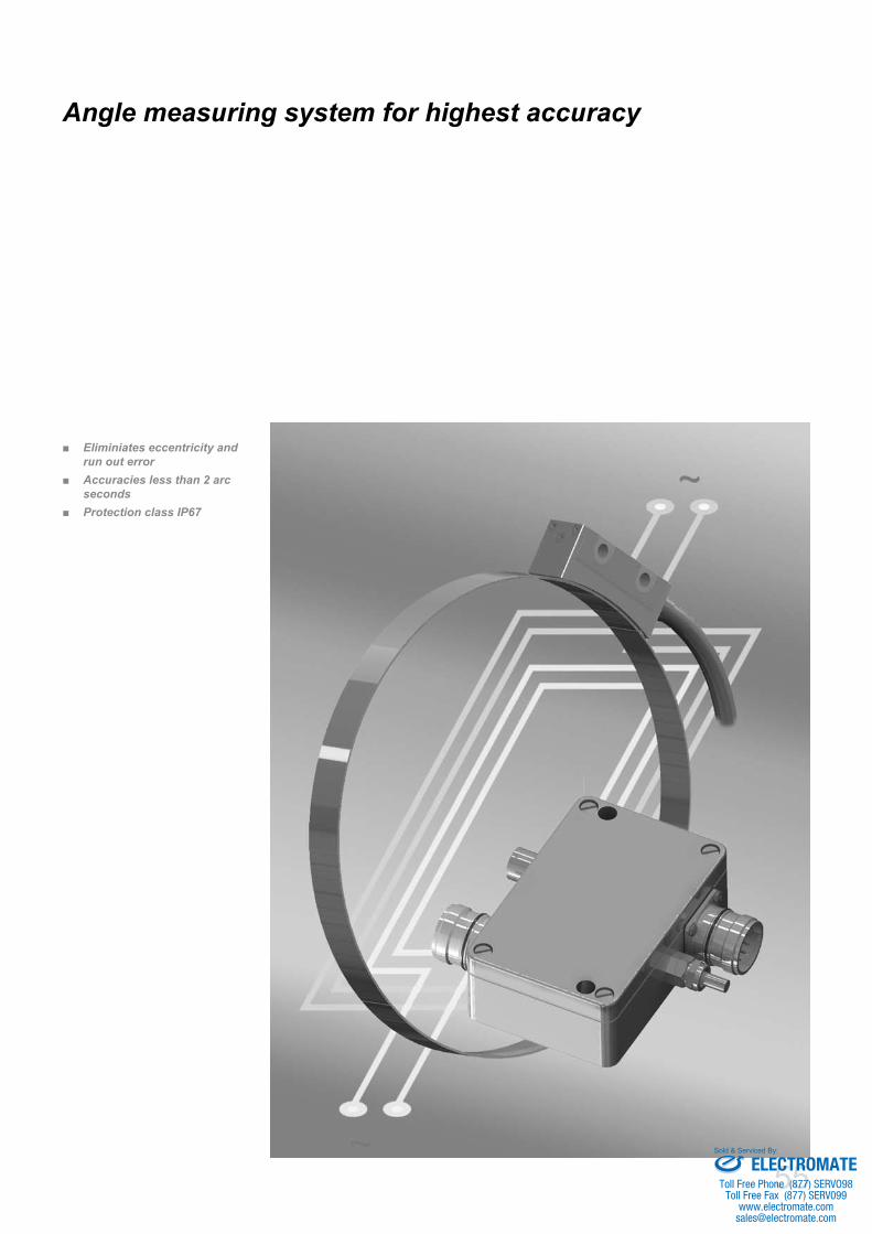
55
Eliminiates eccentricity and ■run out errorAccuracies less than 2 arc ■secondsProtection class IP67 ■
Angle measuring system for highest accuracy
ELECTROMATEToll Free Phone (877) SERVO98
Toll Free Fax (877) SERV099www.electromate.com
Sold & Serviced By:

56
MHS / CHS MehrkopfabtastungMultiple head scanning
Description of multi head scanning
Possible sources of error
Generally it should be noted that each eccentric mounting of an angle measuring system causes an error in measuring position, independent whether there is an integral bearing or not.On a detailed view of possible sources of error on a rotary axis one encounters the following errors:
a) Systematically, repeatable errors per revolution
Eccentricityfrommeasuringflangewithrespecttotheaxisofrotation ■Grating errors of the measuring scale ■Run out errors from the bearing ■
b) Coincidental errors
Backlash of the bearing ■Load-sensitive deformation ■
Sincethesystematicallyerrorsspecifiedaboveareinpracticenotcompletelyavoidable,wepresenttwoeconomiccompensationpossibilities:
MHS ■ – Multiple Head SolutionCHS ■ – Calibration Head Solution
The AMO angle measuring system with multi head scanning provides absolute accuracies of several arc seconds for rotary tables and swivelling axis.Theinfluenceofeccentricitywillbeeliminatedandthesystemaccuracycanbeimproveduptoafactorof4comparedwithasingleheadmeasuring system.
ELECTROMATEToll Free Phone (877) SERVO98
Toll Free Fax (877) SERV099www.electromate.com
Sold & Serviced By:
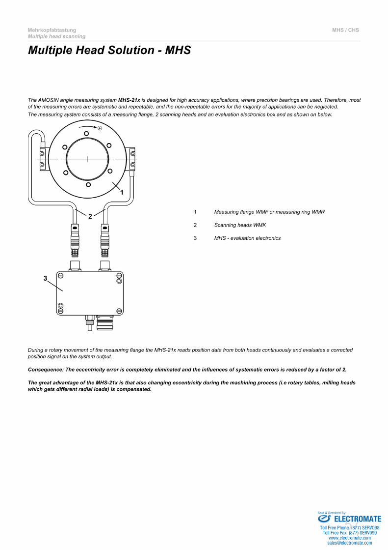
57
MehrkopfabtastungMultiple head scanning
MHS / CHS
Multiple Head Solution - MHS
The AMOSIN angle measuring system MHS-21x is designed for high accuracy applications, where precision bearings are used. Therefore, most of the measuring errors are systematic and repeatable, and the non-repeatable errors for the majority of applications can be neglected. Themeasuringsystemconsistsofameasuringflange,2scanningheadsandanevaluationelectronicsboxandasshownonbelow.
1 MeasuringflangeWMFormeasuringringWMR
2 Scanning heads WMK
3 MHS - evaluation electronics
DuringarotarymovementofthemeasuringflangetheMHS-21xreadspositiondatafrombothheadscontinuouslyandevaluatesacorrectedposition signal on the system output.
Consequence: The eccentricity error is completely eliminated and the influences of systematic errors is reduced by a factor of 2.
The great advantage of the MHS-21x is that also changing eccentricity during the machining process (i.e rotary tables, milling heads which gets different radial loads) is compensated.
ELECTROMATEToll Free Phone (877) SERVO98
Toll Free Fax (877) SERV099www.electromate.com
Sold & Serviced By:

58
MHS / CHS MehrkopfabtastungMultiple head scanning
Calibration Head Solution - CHS
Anhighprecisionanglemeasuringsystemwithmultipleheadscanningprovides,asdescribedabove,asignificantincreaseinsystemaccuracycompared with a single reading head system.The user friendly CHS angle measuring system achieves the accuracy of a multiple head system.The unique feature is that there is only one reading head necessary for normal operation. Only for initial start up of the axis a second reading head has to be mounted for the calibration procedure.TheCHSanglemeasuringsystemconsistsofameasuringflangeormeasuringring,onereadinghead,anevaluationelectronicsandacalibrationunit as shown below.
1 MeasuringflangeWMFormeasuringringWMR
2 Measuring head WMK
3 CHS – evaluation electronics
4 Calibration unit WKE (together with calibration head)
5 Adapter cable for WKE, length 1m
Item 4 and 5 only necessary for calibration procedure
ELECTROMATEToll Free Phone (877) SERVO98
Toll Free Fax (877) SERV099www.electromate.com
Sold & Serviced By:
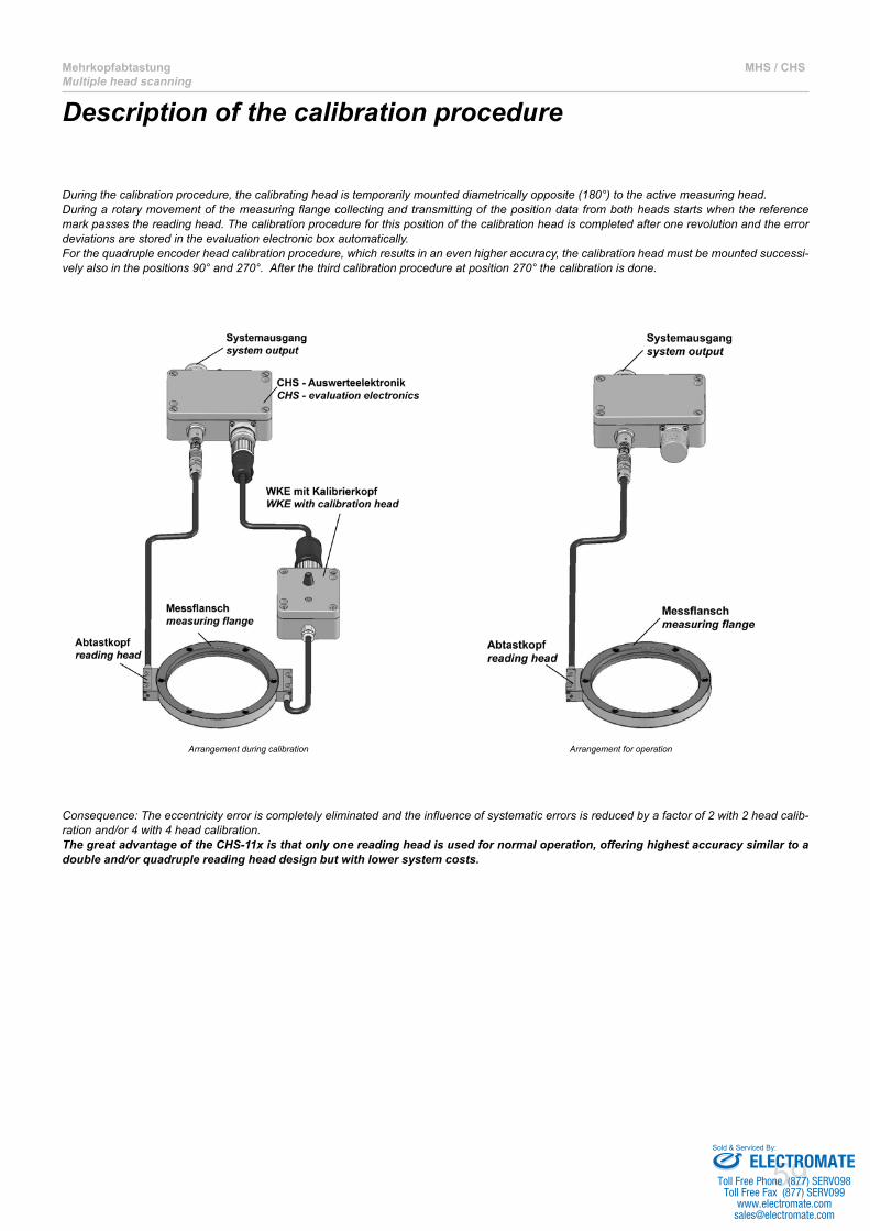
59
MehrkopfabtastungMultiple head scanning
MHS / CHS
Description of the calibration procedure
During the calibration procedure, the calibrating head is temporarily mounted diametrically opposite (180°) to the active measuring head.Duringarotarymovementofthemeasuringflangecollectingandtransmittingofthepositiondatafrombothheadsstartswhenthereferencemark passes the reading head. The calibration procedure for this position of the calibration head is completed after one revolution and the error deviations are stored in the evaluation electronic box automatically. Forthequadrupleencoderheadcalibrationprocedure,whichresultsinanevenhigheraccuracy,thecalibrationheadmustbemountedsuccessi-vely also in the positions 90° and 270°. After the third calibration procedure at position 270° the calibration is done.
Arrangement during calibration Arrangement for operation
Consequence:Theeccentricityerroriscompletelyeliminatedandtheinfluenceofsystematicerrorsisreducedbyafactorof2with2headcalib-ration and/or 4 with 4 head calibration.The great advantage of the CHS-11x is that only one reading head is used for normal operation, offering highest accuracy similar to a double and/or quadruple reading head design but with lower system costs.
ELECTROMATEToll Free Phone (877) SERVO98
Toll Free Fax (877) SERV099www.electromate.com
Sold & Serviced By:

60
MHS / CHS MehrkopfabtastungMultiple head scanning
Metrological consideration
To illustrate the accuracies that can be reached with the CHS are given further measuring diagrams of a system WMI-101-1024 which is a standard angle measuring system with a grating ring of about 326 mm diameter and an accuracy of ±6 arc seconds for a standard single head encoder under ideal mounting conditions, that means no eccentricity.
Measuring flange mounted with 10 µm eccentricity, single head scanning
Theimmensesinusodialdeviationover360°showsthetypicalinfluenceofaneccentricityofonly10µm.Atadiameterof326mmandaneccen-tricity of 10µm the calculated value for the deviation is ±12,6µm and therefore 2 times higher than the accuracy of the measuring flange as shown below.
Error: ± 12,9 "
-15
-10
-5
0
5
10
15
0 45 90 135 180 225 270 315 360
Position [Winkelgrad]Position [degree]
Fehl
er [W
inke
lsek
unde
n]Er
ror [
arcs
ec]
Measuring flange mounted with 10 µm eccentricity, double head scanning with MHS- or CHS-system
WithaCHS-orMHSanglemeasuringsystemwithdoubleheadscanningandanidenticalmeasuringflangewithunchangedeccentricityof10µmthe deviation is as shown below.Theinfluenceofeccentricityiscompletelyeliminated,theerrorofthemeasuringflangeishalvethevaluecomparedtosingleheadscanning.
Error: ± 2,4"
-15
-10
-5
0
5
10
15
0 45 90 135 180 225 270 315 360
Position [Winkelgrad]Position [degree]
Fehl
er [W
inke
lsek
unde
n]Er
ror [
arcs
ec]
ELECTROMATEToll Free Phone (877) SERVO98
Toll Free Fax (877) SERV099www.electromate.com
Sold & Serviced By:

61
MehrkopfabtastungMultiple head scanning
MHS / CHS
Measuring flange mounted with 10 µm eccentricity, quadruple head scanning with CHS-system
With a quadruple head calibration on a CHS-angle measuring system the absolute accuracy of the position is increased again by a factor of 2, as shown in the diagram below.
Error: ± 1,2"
-15
-10
-5
0
5
10
15
0 45 90 135 180 225 270 315 360
Position [Winkelgrad]Position [degree]
Fehl
er [W
inke
lsek
unde
n]Er
ror [
arcs
ec]
The diagrams above show the high accuracy which can be achieved in angle position measurement.
Theobtainablesystemaccuraciesfordifferentsizesofthemeasuringflangeareshowninthetablebelow.
WMF-101 / WMR-101 System accuracySize of measuring
flange / measuring ringOuter diameter
[mm]
Standard single head encoder
[arcsec]
CHS-11xMHS-21x
2-head-calibration
[arcsec]
CHS-11x
4-head-calibration
[arcsec]256 81,95 ± 25 ± 13 ± 7
360 115,12 ± 18 ± 9 ± 5
512 163,54 ± 12,0 ± 6,0 ≤± 3,0
720 229,78 ± 9,0 ± 5,0 ≤± 3,0
900 287,08 ± 7,0 ± 4,0 ≤ ±2,0
1024 326,55 ± 6,0 ± 3,0 ≤ ±2,0
1440 458,97 ± 4,5 ± 2,2 ≤ ±2,0
2048 652,58 ± 3,0 < ±2,0 ≤ ±2,0
ELECTROMATEToll Free Phone (877) SERVO98
Toll Free Fax (877) SERV099www.electromate.com
Sold & Serviced By:
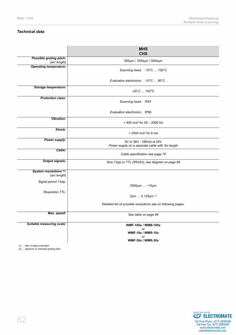
62
MHS / CHS MehrkopfabtastungMultiple head scanning
Technical data
MHSCHS
Possible grating pitch: [arc length] 500µm / 1000µm / 3000µm
Operating temperature:Scanning head: -10°C … 100°C
Evaluation electronics: -10°C … 80°C
Storage temperature:-20°C … 100°C
Protection class:Scanning head: IP67
Evaluation electronics: IP66
Vibration:< 400 m/s² for 55 – 2000 Hz
Shock:< 2000 m/s² for 6 ms
Power supply: 9V to 36V - 180mA at 24VPower supply on a separate cable with 3m length
Cable:Cablespecificationseepage70
Output signals: Sine 1Vpp or TTL (RS422); see diagram on page 69
System resolutions (2): [arc length]
Signal period 1Vpp:3000µm … ~15µm
Resolution TTL:3µm … 0,125µm (1)
Detailed list of possible resolutions see on following pages.
Max. speed: See table on page 66
Suitable measuring scale: WMF-105x / WMB-105x or
WMF-10x / WMR-10xor
WMF-30x / WMR-30x(1) ... after 4-edge evaluation(2) ... depends on selected grating pitch
ELECTROMATEToll Free Phone (877) SERVO98
Toll Free Fax (877) SERV099www.electromate.com
Sold & Serviced By:
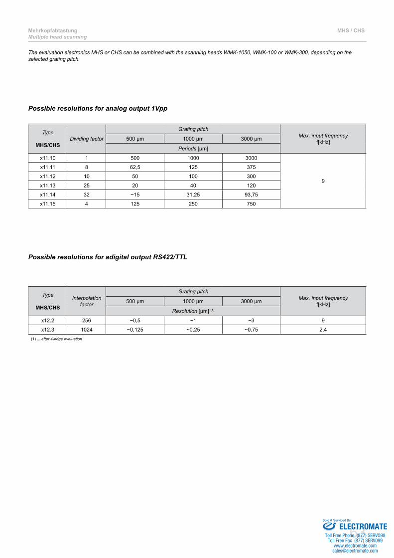
63
MehrkopfabtastungMultiple head scanning
MHS / CHS
The evaluation electronics MHS or CHS can be combined with the scanning heads WMK-1050, WMK-100 or WMK-300, depending on the selected grating pitch.
Possible resolutions for analog output 1Vpp
Type
MHS/CHSDividing factor
Grating pitchMax. input frequency
f[kHz]500 µm 1000 µm 3000 µm
Periods [µm]
x11.10 1 500 1000 3000
9
x11.11 8 62,5 125 375
x11.12 10 50 100 300
x11.13 25 20 40 120
x11.14 32 ~15 31,25 93,75
x11.15 4 125 250 750
Type
MHS/CHS
Interpolation factor
Grating pitchMax. input frequency
f[kHz]500 µm 1000 µm 3000 µm
Resolution [µm] (1)
x12.2 256 ~0,5 ~1 ~3 9
x12.3 1024 ~0,125 ~0,25 ~0,75 2,4(1) ... after 4-edge evaluation
Possible resolutions for adigital output RS422/TTL
ELECTROMATEToll Free Phone (877) SERVO98
Toll Free Fax (877) SERV099www.electromate.com
Sold & Serviced By:

64
MHS / CHS MehrkopfabtastungMultiple head scanning
Ordering code: Scanning head
Ordering code: MHS / CHS TTL-output
Ordering code: MHS / CHS 1 Vpp-output
Ordering code: WKE – Calibration unit
Analog dividing factor
0 ..... 11 ..... 82 ... 103 ... 254 ... 325 ..... 4
MHS-211.1 - 8
CHS-111.1 - 8
Interpolation factor
2 ..... 2563 ..... 1024
MHS-212. - 8
CHS-112. - 8
WKE-1052.4- - 3,0 - 6
WKE-102.4- - 3,0 - 6
WKE-302.4- - 3,0 - 6
Grating pitches / revolution (N)
WMK-1050- - , - 8
WMK-100- - , - 8
WMK-300- - , - 8
Cable length in mGrating pitches / revolution (N) preferred cable length in steps of 0,5m
ELECTROMATEToll Free Phone (877) SERVO98
Toll Free Fax (877) SERV099www.electromate.com
Sold & Serviced By:

65
MehrkopfabtastungMultiple head scanning
MHS / CHS
PIN 1 2 3 4 5 6 7 8 9 10 11 12Signal B- 5V-Sensor RI+ RI- A+ A- - B+ - 0V 0V-Sensor +5VColor white red-white pink grey green yellow - brown - blue blue-white red
Signal +24V 0VColor red blue
Dimensions MHS
64101
34 86
98
36
44
SpannungsversorgungPower supply
Montagebohrungen, Durchmesser 5mmMounting holes,diameter 5mm
Montagebohrungen, Durchmesser 5mmMounting holes,diameter 5mm
Abtastkopf E2Measuring head E2
Abtastkopf E1Measuring head E1
Ausgang MesssystemSystem output
Abtastkopf E1measuring head E1
WKE - KalibriereinheitWKE - calibration unit
Ausgang Messsystemsystem output
Spannungsversorgungpower supply
Montagebohrungen, Durchmesser 5mmmounting holes, diameter 5mm
Dimensions CHS
Thesensepinsareconnectedtothe5V/0VpinsinsidetheMHS/CHStoprovideadefinedvoltagelevelforthesenseinputofasubsequentNC-controller.+5V (pin 12) is not connected to the CHS-electronics, connection of 0V (pin 10) is necessary.It‘s not allowed to connect the pins 7 and 9 to the following electronics (for example controller). These pins serve alone for test purposes only with the AMO testdevice STU-20.Shield of the extension cable must be connected to the housing of the connector.
Plug and connection assignment
Measuring system - signal output
Measuring system - power supply
ELECTROMATEToll Free Phone (877) SERVO98
Toll Free Fax (877) SERV099www.electromate.com
Sold & Serviced By:

66
MHS / CHS MehrkopfabtastungMultiple head scanning
ELECTROMATEToll Free Phone (877) SERVO98
Toll Free Fax (877) SERV099www.electromate.com
Sold & Serviced By:

67
Allgemeine InformationenGeneral information
Maximale DrehzahlenMaximum speed
Maximum speed
a) Max. speed
The maximum speed nmax of a measuring system can be calculated considering the max. input frequency f of the scanning head and the num-ber of pitches per revolution Nofthemeasuringflangeasfollows:
nmax [rpm] = f[Hz] x 60 / N
b) Output frequency
The max. output signal frequency fa of the scanning head depends on the max. speed n used in the application, the number of grating pitches per revolution N and the dividing factor D of a scanning head with 1Vpp output respectively the interpolation factor I of a scanning head with TTL output.It’s important to not exceed the max. input frequency of the subsequent electronics.
fa [Hz] = (n[rpm] / 60) x N x D for scanning head with 1Vpp output
fa [Hz] = (n[rpm] / 60) x N x I for scanning head with TTL output
Maximumrotaryspeedsforstandardmeasuringflangesrespectivelymeasuringringsareshownbelow.
Grating pitch: 500 µm
TypeMax. input frequency
f[khz]
Rotary speed n [rev/min]Standard measuring flange WMF-105x
0512 0720 1024 1440 1800 2048WMK-1x51.1xWMK-2x51.1x 9 1050 750 520 370 300 260
WMK-1x51.30WMK-2x51.30 60 7000 5000 3500 2500 2000 1750
WMK-1x51.S0WMK-2x51.S0 100 11700 8300 5800 4100 3300 2900
WMK-1x52.0/1/CWMK-2x52.0/1/C 19 2200 1580 1100 780 630 550
WMK-1x52.4/EWMK-2x52.4/E 9 1050 750 520 370 300 260
WMK-1x52.5WMK-2x52.5 2,4 280 200 140 100 80 70
WMK-1x52.6/7WMK-2x52.6/7 39 4570 3250 2280 1600 1300 1140
WMK-1x52.A/B/ZWMK-2x52.A/B/Z 39 4570 3250 2280 1600 1300 1140
The values shown above are also valid for the housing WMKF.
ELECTROMATEToll Free Phone (877) SERVO98
Toll Free Fax (877) SERV099www.electromate.com
Sold & Serviced By:

68
Maximale DrehzahlenMaximum speed
Allgemeine InformationenGeneral information
Grating pitch: 1000 µmType
Max. input frequency
f[khz]
Rotary speed n [rev/min]Standard measuring flange WMF-10x or measuring ring WMR-10x
0256 0360 0512 0720 0900 1024WMK-1x1.1xWMK-2x1.1x 9 2100 1500 1050 750 600 520
WMK-1x1.30WMK-2x1.30 60 14000 10000 7000 5000 4000 3500
WMK-1x1.S0WMK-2x1.S0 100 23400 16600 11700 8300 6600 5800
WMK-1x2.0/1/CWMK-2x2.0/1/C 19 4450 3150 2200 1580 1250 1100
WMK-1x2.4/EWMK-2x2.4/E 9 2100 1500 1050 750 600 520
WMK-1x2.5WMK-2x2.5 2,4 560 400 280 200 160 140
WMK-1x2.6/7WMK-2x2.6/7 39 9140 6500 4570 3250 2600 2280
WMK-1x2.A/B/ZWMK-2x2.A/B/Z 39 9140 6500 4570 3250 2600 2280
The values shown above are also valid for the housing WMKF.
Grating pitch: 3000 µm
TypeMax. input frequency
f[khz]
Rotary speed n [rev/min]Measuring ring WMR-30x
0085 0120 0170 0240 0300 0341WMK-3x1.1x 9 6350 4500 3150 2250 1800 1550
WMK-3x1.30 60 42000 30000 21000 15000 12000 10500
WMK-3x1.S0 100 70500 50000 35000 25000 20000 17500
WMK-3x2.0/1/C 19 13400 9500 6700 4750 3800 3340
WMK-3x2.4/E 9 6350 4500 3150 2250 1800 1550
WMK-3x2.5 2,4 1690 1200 840 600 480 420
WMK-3x2.6/7 39 27500 19500 13700 9750 7800 6850
WMK-3x2.A/B/Z 39 27500 19500 13700 9750 7800 6850The values shown above are also valid for the housing WMKF.
ELECTROMATEToll Free Phone (877) SERVO98
Toll Free Fax (877) SERV099www.electromate.com
Sold & Serviced By:

69
Allgemeine InformationenGeneral information
ReferenzmarkenReference marks
Description of the reference marks
In order to determine the absolute angular position, a reference track is integrated onto the scale, parallel to the measuring track. This reference track consists of one or more reference marks (marked on the measuring ring accordingly), which are detected by the scanning head.
The reference marks can be arranged in the following ways:
1. Single reference marks
Single reference marks can be placed at any desired position on the measuring ring. As a standard, a single reference pulse per revolution occurs on the output, assigned to a mounting hole at the measuringflange.
The position of the reference mark on the measuring ring is indicated with a black triangle.
2. Distance-coded reference marks
The coded distribution of the reference marks on the measuring ring allows the controller, if it has implemented this functionality, to determine the absolute position after passing two neighbouring marks.
Thepositionofthefirstreferencemark,thebasicspacingandthepositivedirectionofcountingisindicated on the measuring ring as shown below.
Arrangement of distance coded reference marks
a) Arrangement for non divided output signals
K Number of sine periods at the output of the measuring system
b) Arrangement for divided output signals
K´ Number of divided sine periods at the output of the measuring system
D Dividing factor
Kennzeichnung: Identifier:
ReferenzmarkeReference mark
BasisabstandBasic spacing
Erste BasismarkeFirstbasicmark
Positive ZählrichtungPositive direction of counting
Zählrichtung / Direction of counting
Zählrichtung / Direction of counting
K´ = K x D
WMR-100-0360-K40 WMR-100-0512-K64 WMR-0900-K60
Basic spacing K 40 64 60
Absolute position after max. 29° 28° 18°
Example for distance coded standard measuring rings
ELECTROMATEToll Free Phone (877) SERVO98
Toll Free Fax (877) SERV099www.electromate.com
Sold & Serviced By:

70
AusgangssignaleOutput signals
Allgemeine InformationenGeneral information
Description of the ouput signals
Recommendedconfigurationofthesubsequentelectronics
A, B, RI: direct signal output without dividing factor
A´, B´, RI´: divided signal output
Output signals sine, 1Vpp
Recommendedconfigurationofthesubsequentelectronics
Output signals TTL – RS422
ELECTROMATEToll Free Phone (877) SERVO98
Toll Free Fax (877) SERV099www.electromate.com
Sold & Serviced By:

71
Allgemeine InformationenGeneral information
KabelCable
Cable
Cable for measuring system Extension cableJacket: PUR,highflexible,suitableforenergychains
Diameter: 5,3mm ~ 8mm
Wires: 5 (2 x 0,05) + 1 ( 2 x 0,14) mm2 4 (2 x 0,14) + 2( 2 x 0,5) mm2
Bending radius:Single bending: 5 x d = 25mm 5 x d = 40mm
Continuous bending: 10 x d = 50mm 10 x d = 80mm
Max. length: 9m 50m
Technical data
Ordering code: extension cable
VK - 4 - - -
10 ..... without connector11 ..... 12 pin DIN13 ..... 9 pin SUB-D14 ..... 12 pin CONNEI connector CW15 ..... 15 pin SUB-D16 ..... 12 pin CONNEI coupling CCW19 ..... Special connector or special pin assignments
00 ..... without connector01 ..... 12 pin DIN03 ..... 9 pin SUB-D04 ..... 12 pin CONNEI connector CW05 ..... 15 pin SUB-D06 ..... 12 pin CONNEI coupling CCW09 ..... Special connector or special pin assignments
Cable lengthin meter
Kabellänge /Cable length StiftPin
VerlängerungskabelExtension cable
BuchseSocket
MesssystemMeasuring system
ELECTROMATEToll Free Phone (877) SERVO98
Toll Free Fax (877) SERV099www.electromate.com
Sold & Serviced By:
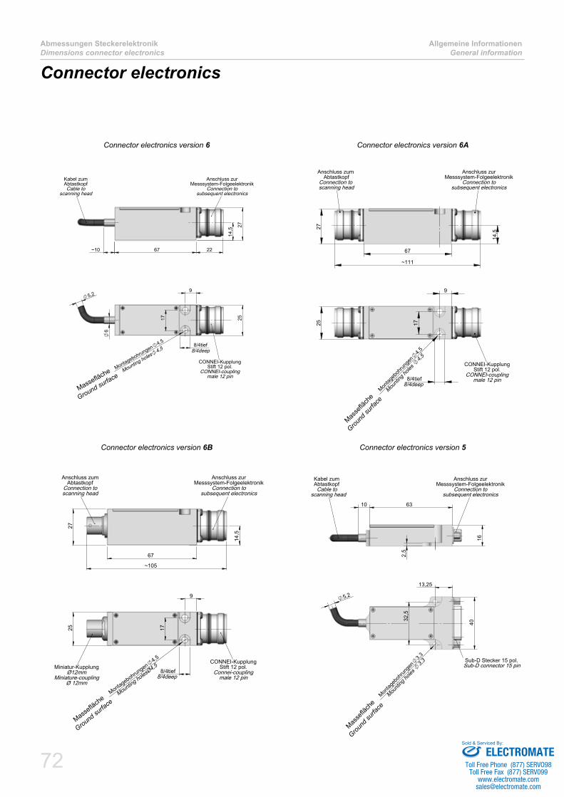
72
Abmessungen SteckerelektronikDimensions connector electronics
Allgemeine InformationenGeneral information
Connector electronics
67~10
27
22
14,5
Anschluss zurMesssystem-Folgeelektronik
Connection tosubsequent electronics
Kabel zumAbtastkopfCable to
scanning head
5,29
17 25
6
8/4tief
Montagebohrungen4,5
CONNEI-KupplungStift 12 pol.
CONNEI-couplingmale 12 pin
8/4deep
Mounting holes4,5
14,5
67
~111
27
Anschluss zurMesssystem-Folgeelektronik
Connection tosubsequent electronics
Anschluss zum Abtastkopf
Connection to scanning head
9
1725
Montag
eboh
runge
n4,5
8/4tief
CONNEI-KupplungStift 12 pol.
CONNEI-couplingmale 12 pin
8/4deepMou
nting
holes
4,5
67
~105
27
14,5
Anschluss zumAbtastkopf
Connection toscanning head
Anschluss zurMesssystem-Folgeelektronik
Connection tosubsequent electronics
9
8/4tief
Montagebohrungen4,5
1725
Miniatur-KupplungØ12mm
Miniature-couplingØ 12mm
CONNEI-KupplungStift 12 pol.
Connei-couplingmale 12 pin8/4deep
Mounting holesØ4,5
10 63
16
2,5
Kabel zum Abtastkopf Cable toscanning head
Anschluss zurMesssystem-Folgeelektronik
Connection tosubsequent electronics
13,25
40
32,5
Montag
eboh
runge
n3,3
5,2
Sub-D Stecker 15 pol.Sub-D connector 15 pin
Mou
nting
holes
3,3
Connector electronics version 6 Connector electronics version 6A
Connector electronics version 6B Connector electronics version 5
Massefläche
Ground surface
Masse
fläch
e
Ground
surfa
ce
Masse
fläch
e
Ground
surfa
ce
Massefläche
Ground surfa
ce
ELECTROMATEToll Free Phone (877) SERVO98
Toll Free Fax (877) SERV099www.electromate.com
Sold & Serviced By:
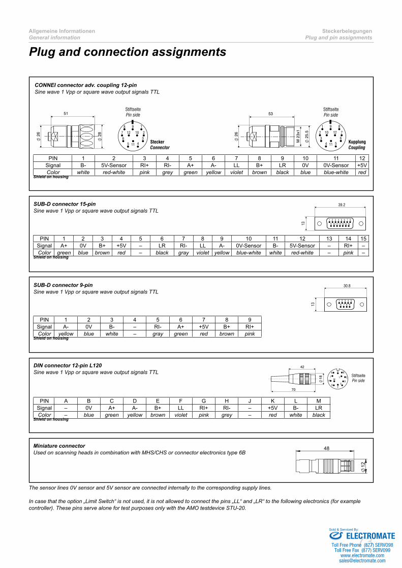
73
Allgemeine InformationenGeneral information
SteckerbelegungenPlug and pin assignments
Plug and connection assignments
SUB-D connector 15-pinSine wave 1 Vpp or square wave output signals TTL
PIN 1 2 3 4 5 6 7 8 9 10 11 12 13 14 15Signal A+ 0V B+ +5V – LR RI- LL A- 0V-Sensor B- 5V-Sensor – RI+ –Color green blue brown red – black gray violet yellow blue-white white red-white – pink –
Shield on housing
CONNEI connector adv. coupling 12-pinSine wave 1 Vpp or square wave output signals TTL
PIN 1 2 3 4 5 6 7 8 9 10 11 12Signal B- 5V-Sensor RI+ RI- A+ A- LL B+ LR 0V 0V-Sensor +5VColor white red-white pink grey green yellow violet brown black blue blue-white red
Shield on housing
DIN connector 12-pin L120Sine wave 1 Vpp or square wave output signals TTL
PIN A B C D E F G H J K L MSignal – 0V A+ A- B+ LL RI+ RI- – +5V B- LRColor – blue green yellow brown violet pink grey – red white black
Shield on housing
Miniature connectorUsed on scanning heads in combination with MHS/CHS or connector electronics type 6B
48
12
SUB-D connector 9-pinSine wave 1 Vpp or square wave output signals TTL
PIN 1 2 3 4 5 6 7 8 9Signal A- 0V B- – RI- A+ +5V B+ RI+Color yellow blue white – gray green red brown pink
Shield on housing
The sensor lines 0V sensor and 5V sensor are connected internally to the corresponding supply lines.
In case that the option „Limit Switch“ is not used, it is not allowed to connect the pins „LL“ and „LR“ to the following electronics (for example controller). These pins serve alone for test purposes only with the AMO testdevice STU-20.
ELECTROMATEToll Free Phone (877) SERVO98
Toll Free Fax (877) SERV099www.electromate.com
Sold & Serviced By:

74
SteckerbelegungenPlug and pin assignments
Allgemeine InformationenGeneral information
ELECTROMATEToll Free Phone (877) SERVO98
Toll Free Fax (877) SERV099www.electromate.com
Sold & Serviced By:

Additional product brochures
LängenmesssystemeLength measuring systems
AMO GmbH
Inkrementelle LÄNGENMESSSYSTEME nach dem induktiven AMOSIN® – Messprinzip
Incremental LENGTH MEASURING SYSTEMS based on the AMOSIN® – Inductive Measuring Principle
SpindelgeberSpindle encoder
Kompakte Bauform ■Compact desig
Höchste Drehzahlen bis zu ■26.000 U/minHigh speeds up to 26,000 rpm
Hohe EMV-Festigkeit ■High EMC immunity
Keine magnetischen ■Komponenten oder Felder, Hysterese oder Entmagneti-sierungsgefahrNo magnetic components No magnetic field hystere-sis or demagnetisation risk
Schutzklasse IP67 ■wasserdichte ImpulsgeberProtection class IP67 Fluid submersible encoders
Spindelgeber nach dem AMOSIN® – MessprinzipSpindle encoder based on the AMOSIN® – Inductive Measuring Principle
AMO GmbH
Product overview
AMO GmbH
Inductive encoders comparable ■to optical encoders in both, accuracy and resolution
No magnetic components, no ■magnetic fields, hysteresis or demagnetisation risk
Protection class IP67 ■Fluid submersible encoders
Product overview:
IncrementalLENGTH- AND ANGLE MEASURINGSYSTEMS based on the AMOSIN® –Inductive Measuring Principle
Produktübersicht
Induktive Messsysteme ■vergleichbar mit optischen Encodern in Genauigkeit und Auflösung
Keine magnetischen ■Komponenten oder Felder, Hysterese oder Entmagneti-sierungs Gefahr
Schutzart IP67 ■wasserdichte Impulsgeber
Produktübersicht:
InkrementelleLÄNGEN- UND WINKELMESSSYSTEME nach dem AMOSIN® – Messprinzip
AMO GmbH
Absolute GeberAbsolute encoders
Auflösung bis zu 25 bit ■Resolution up to 25 bit
Verfügbare Schnittstellen: ■SSI, BiSS/C, Fanuc Available interfaces SSI, BiSS/C, Fanuc
Messlängen bis 32m ■Measuring length up to 32m
Schutzklasse IP67 ■Protection class IP67
Absolutsysteme nach dem induktiven AMOSIN® – MessprinzipAbsolute encoder based on the AMOSIN® – Inductive Measuring Principle
AMO GmbH
ELECTROMATEToll Free Phone (877) SERVO98
Toll Free Fax (877) SERV099www.electromate.com
Sold & Serviced By:

AMO GmbH
ELECTROMATEToll Free Phone (877) SERVO98
Toll Free Fax (877) SERV099www.electromate.com
Sold & Serviced By: