almost-impossible materials science by 3d diffraction ... · the need for speed future directions....
TRANSCRIPT

Almost-Impossible Materials Science
by 3D Diffraction Microscopy
Ian McNulty
BESSY / Advanced Photon Source
16 June 2006

McNulty Almost-Impossible Materials Science 16 June 2006
Outline
Motivation
Resolution and 3D
Coherent methods
The need for speed
Future directions

McNulty Almost-Impossible Materials Science 16 June 2006
The challenge
• The capability to image structure in 3D at the molecular scale and
beyond is essential to solve many problems in materials science
• Electron microscopes, STMs, AFMs, etc., are superb tools but are
limited to surfaces and thin films
• X-ray crystallography is not, but depends on crystalline samples
• Lenses limit the resolution of conventional x-ray microscopes,
and 3D methods are impractically slow for many experiments.
How can we reach beyond these limits?

McNulty Almost-Impossible Materials Science 16 June 2006
We need better tools to study ordering
M. Treacy et al., Rep. Prog. Phys. 68, 2899 (2005)

McNulty Almost-Impossible Materials Science 16 June 2006
Aerogels form interconnected networks
A.. Roshi, S. Barjami, G. Iannacchione (Worchester Polytechnic Inst.)
Aerosils and gels form long, necklace-
like, chains that interconnect randomly
and percolate with fractal dimensions.
Dynamics and fluctuations are
modified by phase transitions in
surrounding matrix (e.g., smectic-
phase liquid crystal)
Gel is locally
distorted by
LC phase

TEM
CH3
O
OHR
X Y
+ Si
MeOOMe
OMe
O
O
+ Al(OsBu)3
Materials Science and Engineering
Block Copolymer directed Hybrids in Bulk
R. Ulrich, A. Du Chesne, M. Templin, U. Wiesner, Adv. Mater. 11, 141 (1999)

McNulty Almost-Impossible Materials Science 16 June 2006
Spin-flip transition TSF is
non-uniform within domain
Diffraction contrast shows regions with different magnetic order
Cr antiferromagnetic domain evolution
P. Evans et al.,Science 295, 1042 (2002)

McNulty Almost-Impossible Materials Science 16 June 2006
We are
hereDiscovery
of x-rays
H. Winick, "Synchrotron
Radiation Sources: A
Primer," (1994)
Need brilliance to get intense, small spot
Flux per spatially coherent mode Fc = B !2/4
McNulty Almost-Impossible Materials Science 16 June 2006
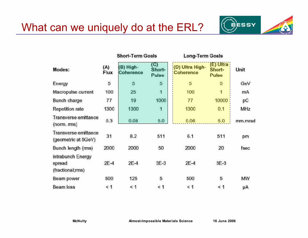
What can we uniquely do at the ERL?

McNulty Almost-Impossible Materials Science 16 June 2006
Image formation as a scattering process
Incident waves with initialmomentum kinc are elastically
scattered into new direction kscatt
with momentum transfer "k.
Ewald sphere (2D) defined by conservation of momentum and limit of spatial
frequencies in the object defined by object composition. Only spatial frequencies onthe Ewald sphere are accessible to the imaging process, limiting attainable resolution.
kscatt
kinc
!k"
kscatt
k inc
Ewald
circle
object spatial
frequency limit
kz
ky
!
k
kx
kzk inc
kscatt

McNulty Almost-Impossible Materials Science 16 June 2006
!
P(x,y) =sin x
x
sin y
y
!
"k = kinc # kscatt
!
kx2
+ ky2
+ (kz + kinc)2
= kinc2
!
(0 " #k " 2kinc)
!
(kz << kinc)
!
kx =2"
2R=2"
#NA
!
kz =kx2
2kinc
!
x =kax
z
!
y =kay
z
Point-spread function
For extreme-angle ray (xz plane, ky = 0) with
Transverse
Longitudinal
!
NA ~a
z
!
k =2"
#
where
with ,
Bragg's law
and
P(x)
kax/z
# 1.0R
!
DOF ="
(NA)2
!
R = 0.5"
NA
Diffraction limits to resolution
x
y
z
a
P(x,y)

McNulty Almost-Impossible Materials Science 16 June 2006
Toward 3D
R ! 0.61 ! / NA DOF ! 1.22 ! / (NA)2 = 2 R2 / (0.61!)
|n| ! 1 $ NA << 1 $ DOF << R
Synthesize larger NA with multiple views
Cannot improve R, only DOF by tomography
! t
! l
RDOF
McNulty Almost-Impossible Materials Science 16 June 2006
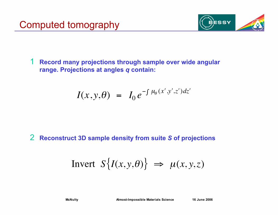
Computed tomography
I(x, y,!) = I0 e" µ! ( # x , # y , # z $ )d # z
Invert S I(x, y,!){ } " µ(x, y, z)
1 Record many projections through sample over wide angular
range. Projections at angles q contain:
2 Reconstruct 3D sample density from suite S of projections

McNulty Almost-Impossible Materials Science 16 June 2006
X-ray microscopy methods
Imaging
Scanning Diffraction
Holography

McNulty Almost-Impossible Materials Science 16 June 2006
Scanning x-ray microscopy/tomography
OSA
scan/rotation
stage
sample
zone plate
APD or
segmented
detector
fluorescence
detector

McNulty Almost-Impossible Materials Science 16 June 2006
Scanning nanotomography of chips
Scanning transmission x-ray micrograph
(1830 eV) of a Cu/W/Si test device, showing
interconnects and vias.
10 µm
Z. Levine et al., Appl. Phys. Lett. 74, 150 (1999)
Bayesian reconstruction reconstruction of 13
STXM projections (±69°, 1573 eV) through two-
level Al/W/Si test object. Al interconnects are
joined by W vias. Two FIB markers are at top.
2 µm

McNulty Almost-Impossible Materials Science 16 June 2006
Detailed study of electromigration void
Z. Levine, et al., J. Appl. Phys. 87, 4483 (2000)
Normal-incidence scan of interconnect
showing electromigration void detail.
Bayesian reconstruction of ragged end of void
McNulty Almost-Impossible Materials Science 16 June 2006
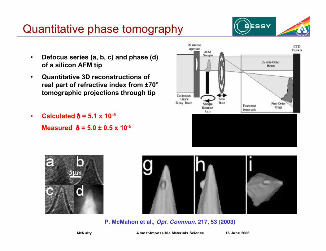
P. McMahon et al., Opt. Commun. 217, 53 (2003)
• Defocus series (a, b, c) and phase (d)
of a silicon AFM tip
• Quantitative 3D reconstructions of
real part of refractive index from ±70°
tomographic projections through tip
• Calculated % = 5.1 x 10⁻⁵
Measured % = 5.0 ± 0.5 x 10⁻⁵
Quantitative phase tomography

McNulty Almost-Impossible Materials Science 16 June 2006
Approaching the limit for focusing x-rays?
Smallest zone drN = 10 nm
NA-limited resolution 24 nm (41% NA)
Photon Energy 19.5 keV
Measured Resolution (1D) 30 nm
Diffraction Efficiency 44%
-150 -100 -50 0 50 100 150
0.0
0.2
0.4
0.6
0.8
1.0
Sample A
Sample B Sample C Gaussian fit
Inte
nsi
ty (
norm
aliz
ed)
!X (nm)
-5000 0 5000 10000 15000 20000!X (nm)
-150 -100 -50 0 50 100 150
0.0
0.2
0.4
0.6
0.8
1.0
Sample A
Sample B Sample C Gaussian fit
Inte
nsi
ty (
norm
aliz
ed)
!X (nm)
-5000 0 5000 10000 15000 20000!X (nm)
-5000 0 5000 10000 15000 20000!X (nm)
Kang et al., Phys. Rev. Lett. 96, 127401 (2006)
Sectioned graded-period multilayer
Ideal MLL structure:
~1 nm resolution feasible
2D diffraction efficiency > 50%
Tilted MLL: 5 nm resolution feasible
2D MLL
1D MLL

McNulty Almost-Impossible Materials Science 16 June 2006
Optics limitations
Achieving high NA is challenging because x-rays interact weakly
n = 1 - % - i& %,& ~ 10-3 to 10-6 $ |n| ! 1
Refractive (compound refractive lenses) ~ 50 nm
Low efficiency, highly chromatic, significant aberrations
Reflective (Kirkpatrick-Baez mirrors) ~ 40 nm
High efficiency, achromatic, but limited to ~10 nm by Qc
Diffractive (Fresnel zone plates, MLLs) ~ 18 nm
Limited to ~10 nm by aspect ratio, except MLL
Crystal lenses (impractical)
High angular resolution, but insufficient angular coverage
~5 nm ?
McNulty Almost-Impossible Materials Science 16 June 2006
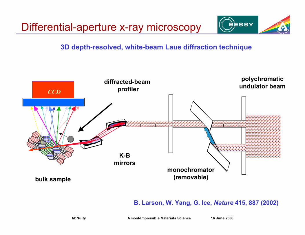
3D depth-resolved, white-beam Laue diffraction technique
polychromatic
undulator beam
CCD
K-B
mirrorsmonochromator
(removable)
diffracted-beam
profiler
bulk sample
B. Larson, W. Yang, G. Ice, Nature 415, 887 (2002)
Differential-aperture x-ray microscopy

McNulty Almost-Impossible Materials Science 16 June 2006
• Intra- and inter-granular information
• Grain boundary morphology and type
• Misorientation axis/angle between grains
• 3D microtexture
• Grain size-distribution
5'6 '31 µm3 volume in Al polycrystal
W. Yang, B. Larson, G. Ice, Micron 35, 431 (2004)
1
2
4
6
10
2
4
6
100
2
4
6050403020
Rotation angle (°)Relative Orientation (o)
5 µmTEM - Polycrystal Al
diffracted
beam profiler
CCD
microbeam
Studying 3D Al structure by DAXM
McNulty Almost-Impossible Materials Science 16 June 2006
Real vs. reciprocal-space methods
• Resolution of real-space methods is fundamentally limited by
optics technology. Because n ~ 1 for x-rays, NA << 1 and DOF
<< R (like electrons).
• Reciprocal-space methods can benefit from high resolution
detectors and optics ...
$ But the resolution ultimately depends on neither.
R and DOF are limited only by ! and usable signal.

McNulty Almost-Impossible Materials Science 16 June 2006
Coherent diffraction microscopy
• X-ray coherent diffraction is a lensless method suited for 3D
imaging of non-crystalline structures
• Resolution limited only by measurable momentum transfer (NA)
• But: have phase problem - full recovery is required, must assume
some a priori information, e.g. object extent
J. Miao et al., Nature 400, 342 (1999)

McNulty Almost-Impossible Materials Science 16 June 2006
Diffraction approach
• Phase information is obtained by measuring diffraction
pattern at sufficiently fine intervals
• Reconstruct object amplitude by guessing at phase, then
iteratively improving guess to get self-consistent solution
• Resolution: transverse R ~ 0.61 !/NA
longitudinal DOF ~ 1.22 !/(NA)2
Contrast: ( |f12 + f2
2|
!
I = a2
Record coherent diffraction pattern

McNulty Almost-Impossible Materials Science 16 June 2006
R. Gerchberg and W. Saxton, Optik 35, 237 (1972)
J. R. Fienup, Appl. Opt. 21, 2758 (1982)
Phasing by iterative error reduction

McNulty Almost-Impossible Materials Science 16 June 2006
Biological objects
Reconstructed coherent diffraction
images of a freeze-dried yeast cell
viewed at (A) normal, (C) 3°, and (D)
4° off-normal incidence. Labels
identify the nucleus (N), a storage
vacuole (V), and cell membrane (M).
Image brightness represents
magnitude, hue represents phase.
(B) STXM image taken of the same
cell using 540-eV x-rays at ~42 nm
resolution.
D. Shapiro et al., PNAS 102, 15343 (2005)

McNulty Almost-Impossible Materials Science 16 June 2006
Optimizing sample contrast
• Optimizing contrast for biological specimens such as
cytoskeletal actin filaments and mineralized fish bone
• Exploring resonant enhancement at absorption edges
Coherent diffraction pattern
(2.2 keV) from a fish bone at
a low mineralization state
Image of fish bone reconstructed
solely from diffraction data
1 "m
J. Miao, C. Song (UCLA)

McNulty Almost-Impossible Materials Science 16 June 2006
Holographic approach
• Reference wave encodes magnitude and phase of wave
scattered by object in hologram
• Contrast and resolution: same as for coherent diffraction
• Reconstruct sample amplitude by "re-illuminating"
hologram with reference wave (or its C.C.)
!
I = a+b2
= a2
+ b2
+a*b+ab*
!
bI = ba2
+bb2
+a*bb+abb*
= aIb + b Ia +Ib( ) + background
Record hologram
Reconstruct

McNulty Almost-Impossible Materials Science 16 June 2006
Holography
Gabor
plane reference wave
(in-line)
Fourier Transform
spherical reference wave
(off-axis)
D. Gabor, Nature 161, 777 (1948) G. Stroke, Appl. Phys. Lett. 6, 201 (1965)
Winthrop, Worthington, Phys. Lett. 15, 124 (1965)
McNulty Almost-Impossible Materials Science 16 June 2006
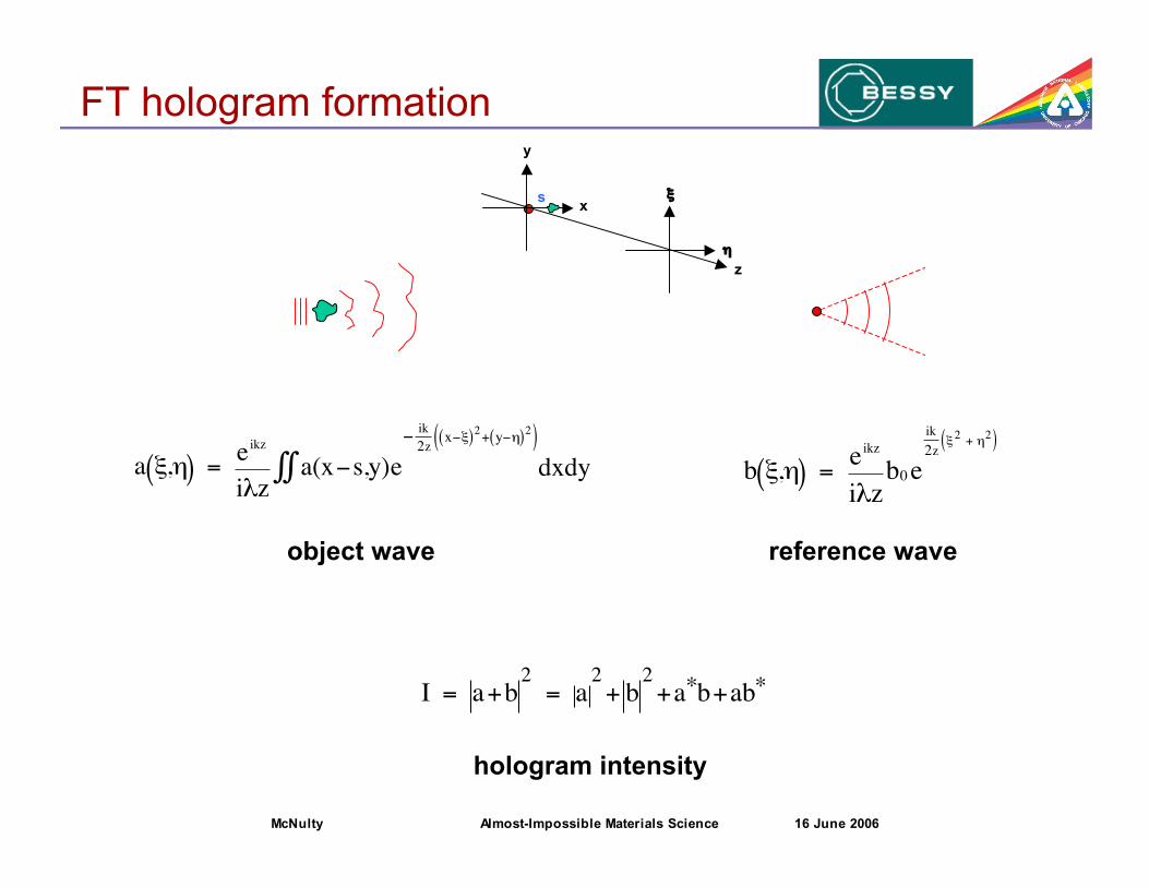
FT hologram formation
hologram intensity!
I = a+b2
= a2
+ b2
+a*b+ab*
!
a ",#( ) = eikz
i$za(x%s,y)e
%ik
2zx%"( )
2+ y%#( )
2( )&& dxdy
object wave reference wave!
b ",#( ) = e
ikz
i$zb0 e
ik
2z"2 + #2( )
x
y
z
s
)
*

McNulty Almost-Impossible Materials Science 16 June 2006
Reconstruction
!
FT"1 a*b +ab*{ } = f x" s,y( ) a x" s,y( ) + f " x" s( ),"y( )* a " x" s( ),"y( )*
• Numerically take FT of hologram intensity to reconstruct
• Spatially separated primary, conjugate object waves result
• Weak curvature f(x,y) on object wave can be ignored
!
F ",#( ) = eikz
i$zf ",#( ) a(x,y)f(x,y)e
%ik
zx"+y#( )
&& dxdy
!
f ",#( ) = e
ik
2z"2 + #2( )
where:
and
!
" s,#( ) = e$
ik
zs#
,
!
a*b+ab* = " s#( )F #,$( )+" s#( )*F #,$( )
*Image terms:

McNulty Almost-Impossible Materials Science 16 June 2006
60 70 80 90 100 110
Production Year
1E-3
1E-2
1E-1
1E+0
1E+1
1E+2
1E+3
1E+4
1E+5
1E+6
Are
al D
en
sity
Meg
ab
its/in
2
Areal Density Perspective44 Years of Technology Progress
IBM RAMAC (First Hard Disk Drive)
8.5 Million X Increase
1st MR Head
1st GMR Head
1st Thin Film Head
2000 2010
105
104
103
102
10
1
10-1
10-2
10-3
Ed Grochowski at Almaden
25% CGR
60% CGR
arp
ers
2000ac.p
rz
Travelstar 30GT
Ultrastar 73LZX
Deskstar 40GV
100% CGR
106
Microdrive II
IBM Disk Drive Products
Industry Lab Demos
Production year
0.03
0.08
0.3
0.8
3
8
30
80
300
800
Linear bit size (µm)
106
105
104
103
102
101
1
10-1
10-2
10-3
Areal density
(MegaBits/inch2)
(first hard disk)
IBM Product
Industry Demo
IBM Almaden
Hard disks: storage density

McNulty Almost-Impossible Materials Science 16 June 2006
Sample: O. Hellwig (Hitachi)
SiNx / Pt (24 nm) /
[Co (1.2 nm) / Pt (0.7 nm)]50 /
Pt (1.5 nm)
perpendicular anisotropy
5 µm x 5 µm
MFM, top viewside view
M
M
CoPt
+ magnetic storage media
continuous object
CoPt magnetic labyrinth nanostructures

McNulty Almost-Impossible Materials Science 16 June 2006
SEM
Au mask
SiN membranex
Magnetic film
20 m pinholeµ
mask and sample
2 µm
UE56/1 SGM
beamline
SEM
Au mask
SiN membranex
Magnetic film
20 m pinholeµ
mask and sample
worm domains
coherent illumination
Pinhole mask method
Co 2p3/2 XMCD:
778 eV
1.59 nm

McNulty Almost-Impossible Materials Science 16 June 2006
* *
FTH STXM
W. Schlotter
Y. Acremann
Resolution
30-40 nm
W
B
*Reconstructed
resolution ~50 nm
, 1.5 µm
100 nm
RCP-LCP
S. Eisebitt et al.,
Nature 432, 885 (2004)

McNulty Almost-Impossible Materials Science 16 June 2006
Nature Materials 4, 203 (2005)
[Co (0.3 nm) Pd (0.8 nm)]8
, 330 nm
, 110 nm
MFM
SE
M
Switching in patterned magnetic media

McNulty Almost-Impossible Materials Science 16 June 2006
Nanostructure of multi-twinned crystals
Z. Xiao et al., J. Am. Chem. Soc. 126, 2316 (2004)
• Multi-twinned Pb crystals >5 "m in size are readily grown
by electrodeposition. Morphology is strongly dependent
on the electrochemical potential
• Calculations indicate they should not grow larger
than ~200 nm due to strain near grain boundaries
• Even highly regular “crystals” show
little or no Bragg diffraction
• If crystals, what is their structure,
orientation, and nature of defects?
• Are they amorphous?
If so, how do they grow?

McNulty Almost-Impossible Materials Science 16 June 2006
Fourier transform experiment
• Beam passing through zone plate (0th-order) illuminates sample.
• Beam focused by zone plate (3rd-order) serves as reference.
Reference wave interferes with object wave to form hologram.
• NA of reference wave determines hologram resolution.
Detector resolution determines object field of view.
Zone Plate
Coherent
X-rays
Sample
Pinhole
2.3 mm 1.12 m
NA
CCD
Beam Stop

McNulty Almost-Impossible Materials Science 16 June 2006
Sample
Y. Xiao (APS), Z. Xiao (ANL/MSD)

McNulty Almost-Impossible Materials Science 16 June 2006
Only part of hologram recorded
• limit direct-beam blooming
• increase angular resolution
• collect un-phased diffraction
... but pay penalty:
• much sample information not
recorded, especially at lowest
spatial resolution
Holograms
5 mm
FT
hologramcoherent
diffraction
s
Q(r)

McNulty Almost-Impossible Materials Science 16 June 2006
Reconstructed holograms
Closeup SEM of Pb crystal.
Crystal is ~4.5 "m in extent;
dendrites are 100-300 nm wide.
Reconstructed FT hologram. Field of
view is limited to ~5 "m by detector
resolution. X-ray energy was 1050 eV.
3 "m
McNulty Almost-Impossible Materials Science 16 June 2006
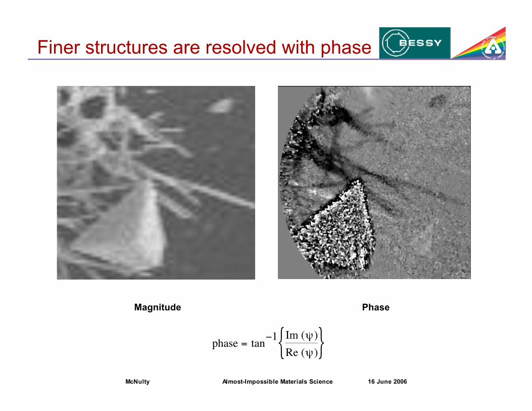
Finer structures are resolved with phase
PhaseMagnitude
!
phase = tan"1 Im (#)
Re (#){ }

McNulty Almost-Impossible Materials Science 16 June 2006
50 nm
16 nm
Coherent diffraction is aided by Fresnel
G. Williams, K. Nugent (U. Melbourne)

McNulty Almost-Impossible Materials Science 16 June 2006
Fresnel diffraction imaging
Phase Magnitude with
color-encoded phase

McNulty Almost-Impossible Materials Science 16 June 2006
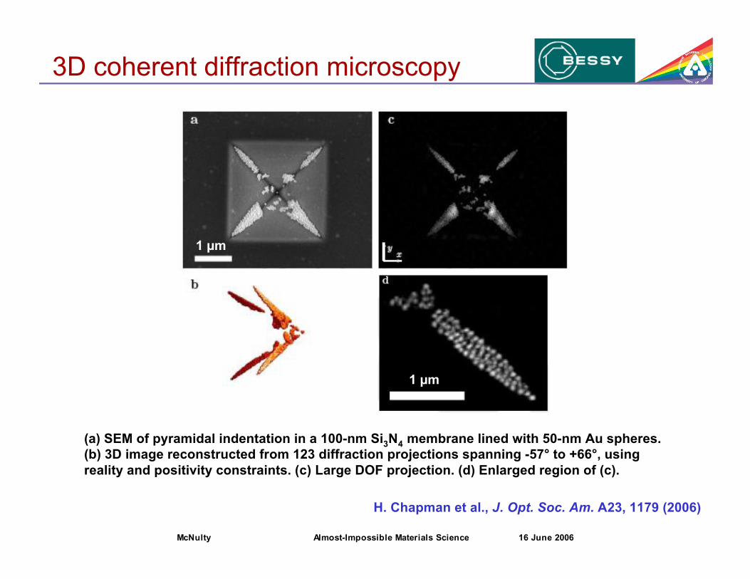
3D coherent diffraction microscopy
(a) SEM of pyramidal indentation in a 100-nm Si3N4 membrane lined with 50-nm Au spheres.
(b) 3D image reconstructed from 123 diffraction projections spanning -57° to +66°, using
reality and positivity constraints. (c) Large DOF projection. (d) Enlarged region of (c).
H. Chapman et al., J. Opt. Soc. Am. A23, 1179 (2006)
1 "m
1 "m
McNulty Almost-Impossible Materials Science 16 June 2006
3D coherent diffraction microscopy
(a) SEM of pyramidal indentation in a 100-nm Si3N4 membrane lined with 50-nm Au spheres.
(b) 3D image reconstructed from 123 diffraction projections spanning -57° to +66°, using
reality and positivity constraints. (c) Large DOF projection. (d) Enlarged region of (c).
H. Chapman et al., J. Opt. Soc. Am. A23, 1179 (2006)
1 "m
1 "m

McNulty Almost-Impossible Materials Science 16 June 2006
Tomography at the nanoscale
Technically challenging
– Precision sample rotation and targeting in x,y,z
– Short working distance at high NA (using optics)
– Radiation dose to sample (but Dose fractionation helps)
Physical limitations restrict
– Accessible angular range
– Number of views obtainable
– Sample field-of-view
... time consuming!
$ Parallelize projection acquisition

McNulty Almost-Impossible Materials Science 16 June 2006
Multi-view holography with beamsplitter
Possible method for one-shot tomography. Six holograms
are shown but they are part of a 2D array of 7x7-1 = 48
M.R. Howells,
Proc. LCLS Workshop (1994)
Livermore team developed
multiview method using
several (e.g. 4) off-axis ZPs

McNulty Almost-Impossible Materials Science 16 June 2006
Multiple illumination directions
Micromachined Si mirror nano-
actuators for x-ray astronomy
Parallel tomographic coherent
diffraction. N beams are directed
through sample onto N detectors
M. Schattenberg, MIT

McNulty Almost-Impossible Materials Science 16 June 2006
What we've learned
• Coherent diffraction microscopy is getting easier, but
phase retrieval is slow and uniqueness problem not solved.
• Holograms are quickly and reliably reconstructed in
seconds on a small computer. Pinholes give cleanest
results, but ZPs are best for sample and scalable to hard
x-rays. Holographic data aids diffraction phase recovery.
• Currently takes ~1010 photons for ~50 nm resolution (2D).
ERL should provide enough coherent flux for 3D data set
at same resolution and in same time.

McNulty Almost-Impossible Materials Science 16 June 2006
Stanford 1878
Snapshots: smaller & faster

McNulty Almost-Impossible Materials Science 16 June 2006
Ultrafast
Today Lasers
X-rays
One day ... ps magnetic imaging?
J. Stohr (Stanford U.)

McNulty Almost-Impossible Materials Science 16 June 2006
Conclusions
• X-ray microscopy is now being used to image nanoscale 3D
structures at 3rd-generation sources, but acquisition takes days.
• Coherent diffraction avoids optics limitations and can be
combined with tomography for 3D imaging. Parallel data
collection will enable time-resolved studies.
• Materials science at the nanometer scale, especially time-resolved
problems, will benefit from the 1000x higher brilliance of the ERL.

McNulty Almost-Impossible Materials Science 16 June 2006
Acknowledgements
Stefan Eisebitt, Chris Günther, BESSY
Andreas Menzel, Florin Radu
Lixin Fan, Yanan Xiao Advanced Photon Source
David Paterson Australian Synchrotron
Jianwei Miao, Changyong Song U. California at Las Angeles
Keith Nugent, Andrew Peele University of Melbourne
Bill Schlotter Stanford University
Olaf Hellwig Hitachi Almaden Res. Center
BESSY, EU Marie Curie Foundation, U.S. Dept. of Energy OS-BES