allen-bradley controllogix ethernet driver - kepware.com · allen-bradleycontrollogixethernetdriver...
TRANSCRIPT
Allen-Bradley ControlLogix EthernetDriver
© 2018 PTC Inc. All Rights Reserved.

Allen-Bradley ControlLogix Ethernet Driver
Table of Contents
Allen-Bradley ControlLogix Ethernet Driver 1
Table of Contents 2
Allen-Bradley ControlLogix Ethernet Driver 11
Overview 12
Setup 14
Channel Setup 16
Channel Properties — General 16
Channel Properties — Ethernet Communications 17
Channel Properties — Write Optimizations 17
Channel Properties — Advanced 18
Device Setup 20
Device Properties - Identification 20
Device Properties — Operating Mode 20
Device Properties — Scan Mode 21
Device Properties — Timing 22
Device Properties — Auto-Demotion 23
Device Properties — Tag Generation 24
Device Properties — Logix Communications Parameters 26
Device Properties — Logix Options 26
Device Properties — Logix Database Settings 28
Device Properties — ENI DF1/DH+/CN Gateway Communications Parameters 29
Block Writes 30
Device Properties - SLC 500 Slot Configuration 31
Device Properties — Redundancy 32
SLC 500 Modular I/O Selection Guide 32
Performance Optimizations 35
Optimizing Communications 35
Optimizing the Application 37
Performance Statistics and Tuning 38
Performance Tuning Example 39
Data Types Description 51
Default Data Type Conditions 51
Address Descriptions 53
Logix Addressing 54
MicroLogix Addressing 55
www.ptc.com
2
Allen-Bradley ControlLogix Ethernet Driver
SLC 500 Fixed I/O Addressing 57
SLC 500 Modular I/O Addressing 58
PLC-5 Series Addressing 59
Logix Tag-Based Addressing 61
Address Formats 62
Tag Scope 63
Internal Tags 64
Predefined Term Tags 64
Addressing Atomic Data Types 65
Addressing Structure Data Types 66
Addressing STRING Data Type 66
Ordering of Logix Array Data 67
Logix Advanced Addressing 69
Advanced Addressing: BOOL 69
Advanced Addressing: SINT 70
Advanced Addressing: INT 73
Advanced Addressing: DINT 75
Advanced Addressing: LINT 78
Advanced Addressing: REAL 79
File Listing 82
Output Files 83
Input Files 86
Status Files 90
Binary Files 91
Timer Files 91
Counter Files 92
Control Files 93
Integer Files 94
Float Files 95
ASCII Files 95
String Files 96
BCD Files 97
Long Files 97
MicroLogix PID Files 98
PID Files 99
MicroLogix Message Files 101
Message Files 102
Block Transfer Files 103
www.ptc.com
3

Allen-Bradley ControlLogix Ethernet Driver
Function Files 104
High-Speed Counter File (HSC) 104
Real-Time Clock File (RTC) 105
Channel 0 Communication Status File (CS0) 106
Channel 1 Communication Status File (CS1) 107
I/O Module Status File (IOS) 107
Automatic Tag Database Generation 109
Tag Hierarchy 109
Controller-to-Server Name Conversions 112
Preparing for Automatic Tag Database Generation 112
Error Codes 114
Encapsulation Error Codes 114
CIP Error Codes 114
0x0001 Extended Error Codes 115
0x001F Extended Error Codes 116
0x00FF Extended Error Codes 116
Event Log Messages 117
The following errors occurred uploading controller project from device. Resorting to SymbolicProtocol. 117
Invalid or corrupt controller project detected while synchronizing. Synchronization will be retriedshortly. 117
Project download detected while synchronizing. Synchronization will be retried shortly. 117
Database error. Data type for reference tag unknown. Setting alias tag data type to default. |Reference tag = '<tag>', Alias tag = '<tag>', Default data type = '<type>'. 117
Database error. Member data type not found in tag import file. Setting data type to default. |Member data type = '<type>', UDT = '<type>', Default data type '<type>'. 118
Database error. Data type not found in tag import file. Tag not added. | Data type = '<type>', Tagname = '<tag>'. 118
Database error. Error occurred processing alias tag. Tag not added. | Alias tag = '<tag>'. 118
Database error. Encapsulation error occurred during register session request. | Encapsulationerror = <code>. 119
Database error. Framing error occurred during register session request. 119
Database error. Encapsulation error occurred during fwd. open request. | Encapsulation error =<code>. 119
Database error. Framing error occurred during forward open request. 119
Database error. Error occurred during forward open request. | CIP error = <code>, Extendederror = <code>. 119
Database error. Encapsulation error occurred while uploading project information. |Encapsulation error = <code>. 119
Database error. Error occurred while uploading project information. | CIP error = <code>, 120
www.ptc.com
4

Allen-Bradley ControlLogix Ethernet Driver
Extended error = <code>.
Database error. Framing error occurred while uploading project information. 120
Database error. Internal error occurred. 121
Database error. Encapsulation error occurred while uploading program information. | Programname = '<name>', Encapsulation error = <code>. 121
Database error. Error occurred while uploading program information. | Program name ='<name>', CIP error = <code>, Extended error = <code>. 121
Database error. Framing error occurred while uploading program information. | Program name= '<name>'. 122
Database error. Unable to resolve CIP data type for tag. Setting to default type. | CIP data type =<type>, Tag name = '<tag>', Default data type = '<type>'. 122
Encapsulation error occurred while uploading project information. | Encapsulation error =<code>. 122
Error occurred while uploading project information. | CIP error = <code>, Extended error =<code>. 123
Framing error occurred while uploading project information. 123
Encapsulation error occurred while uploading program information. | Program name ='<name>', Encapsulation error = <code>. 124
Error occurred while uploading program information. | Program name = '<name>', CIP error =<code>, Extended error = <code>. 124
Framing error occurred while uploading program information. | Program name = '<name>'. 124
Encapsulation error occurred while uploading controller program information. Encapsulationerror = <code>. 124
Error occurred while uploading controller program information. CIP error = <code>, Extendederror = <code>. 124
Framing error occurred while uploading controller program information. 124
CIP connection timed out while uploading project information. 124
Database error. CIP connection timed out while uploading project information. 124
Database error. No more connections available for fwd. open request. 125
Error opening file for tag database import. | OS error = '<code>'. 125
Controller not supported. | Vendor ID = <ID>, Product type = <type>, Product code = <code>,Product name = '<name>'. 125
Frame received from device contains errors. 125
Write request failed due to a framing error. | Tag address = '<address>'. 125
Read request for tag failed due to a framing error. | Tag address = '<address>'. 126
Block read request failed due to a framing error. | Block size = <number> (elements), Block startaddress = '<address>'. 126
Block read request failed due to a framing error. | Block size = <number> (bytes), Block name ='<name>'. 126
Unable to write to tag. | Tag address = '<address>', CIP error = <code>, Extended error =<code>. 127
Unable to read tag. | Tag address = '<address>', CIP error = <code>, Extended error = <code>. 127
www.ptc.com
5

Allen-Bradley ControlLogix Ethernet Driver
Unable to read block. | Block size = <number> (elements), Block start address = '<address>', CIPerror = <code>, Extended error = <code>. 127
Unable to read block. | Block size = <number> (bytes), Tag name = '<tag>', CIP error = <code>,Extended error = <code>. 128
Unable to write to tag. Controller tag data type unknown. | Tag address = '<address>', Data type= <type>. 128
Unable to read tag. Controller tag data type unknown. Tag deactivated. | Tag address ='<address>', Data type = <type>. 128
Unable to read block. Controller tag data type unknown. Block deactivated. | Block size =<number> (elements), Block start address = '<address>', Data type = <type>. 128
Unable to write to tag. Data type not supported. | Tag address = '<address>', Data type ='<type>'. 129
Unable to read tag. Data type not supported. Tag deactivated. | Tag address = '<address>', Datatype = '<type>'. 129
Unable to read block. Data type not supported. Block deactivated. | Block size = <number>(elements), Block start address = '<address>', Data type = '<type>'. 129
Unable to write to tag. Data type is illegal for this tag. | Tag address = '<address>', Data type ='<type>'. 130
Unable to read tag. Data type is illegal for this tag. Tag deactivated | Tag address = '<address>',Data type = '<type>'. 130
Unable to read block. Data type is illegal for this block. Block deactivated. | Block size =<number> (elements), Block start address = '<address>', Data type = '<type>'. 130
Unable to write to tag. Tag does not support multi-element arrays. | Tag address = '<address>'. 131
Unable to read tag. Tag does not support multi-element arrays. Tag deactivated. | Tag address= '<address>'. 131
Unable to read block. Block does not support multi-element arrays. Block deactivated. | Blocksize = <number> (elements), Block start address = '<address>'. 131
Unable to write to tag. Native tag size mismatch. | Tag address = '<address>'. 132
Unable to read tag. Native tag size mismatch. | Tag address = '<address>'. 132
Unable to read block. Native tag size mismatch. | Block size = <number> (elements), Block startaddress = '<address>'. 132
Unable to read block. Native tag size mismatch. | Block size = <number> (bytes), Block name ='<name>'. 133
Unable to write to tag. | Tag address = '<address>'. 133
Unable to read tag. Tag deactivated. | Tag address = '<address>'. 133
Unable to read block. Block deactivated. | Block size = <number> (elements), Block startaddress = '<address>'. 134
Unable to read block. Block deactivated. | Block size = <number> (bytes), Tag name = '<tag>'. 134
Error occurred during a request to device. | CIP error = <code>, Extended error = <code>. 135
Encapsulation error occurred during a request to device. | Encapsulation error = <code>. 135
Memory could not be allocated for tag. | Tag address = '<address>'. 135
Unable to read block. Frame received contains errors. | Block size = <number> (elements),Starting address = '<address>'. 136
www.ptc.com
6
Allen-Bradley ControlLogix Ethernet Driver
Unable to read function file from device. Frame received contains errors. | Function file ='<name>'. 136
Unable to read block. Tags deactivated. | Block size = <number> (elements), Starting address ='<address>', DF1 status = <code>, Extended status = <code>. 136
Unable to read function file from device. Tags deactivated. | Function file = '<name>', DF1 status= <code>, Extended status = <code>. 137
Unable to write to address. Frame received contains errors. | Address = '<address>'. 137
Unable to write to function file. Frame received contains errors. | Function file = '<name>'. 137
Unable to read block. | Block size = <number> (elements), Starting address = '<address>', DF1status = <code>, Extended status = <code>. 137
Unable to read function file. | Function file = '<name>', DF1 status = <code>, Extended status =<code>. 138
Unable to read block. Tags deactivated. | Block size = <number> (elements), Starting address ='<address>', DF1 status = <code>, Extended status = <code>. 138
Unable to read function file. Tags deactivated. | Function file = '<name>', DF1 status = <code>. 139
Unable to write to address. | Address = '<address>', DF1 status = <code>, Extended status =<code>. 139
Unable to write to function file. | Function file = '<name>', DF1 status = <code>, Extended status= <code>. 140
Unable to read block. | Block size = <number> (elements), Starting address = '<address>', DF1status = <code>. 140
Unable to read function file. | Function file = '<name>', DF1 status = <code>. 141
Unable to write to address. | Address = '<address>', DF1 status = <code>. 141
Unable to write to function file. | Function file = '<name>', DF1 status = <code>. 141
Unable to read tag. Internal memory is invalid. | Tag address = '<address>'. 142
Unable to read tag. Data type is illegal for this tag. | Tag address = '<address>', Data type ='<type>'. 142
Unable to read block. Internal memory is invalid. Tag deactivated. | Tag address = '<address>'. 142
Unable to read block. Internal memory is invalid. Block deactivated. | Block size = <number>(elements), Block start address = '<address>'. 143
Unable to write to address. Internal memory is invalid. | Tag address = '<address>'. 143
Unable to read block. Block deactivated. | Block size = <number> (elements), Block startaddress = '<address>', CIP error = <code>, Extended error = <code>. 143
Device not responding. Local node responded with error. | DF1 status = <code>. 143
Unable to write to function file. Local node responded with error. | Function file = '<name>', DF1status = <code>. 143
Unable to write to address. Local node responded with error. | Function file = '<name>', DF1status = <code>. 144
Unexpected offset encountered for tag. Tag will use Symbolic protocol. | Tag address ='<address>'. 144
Unexpected offset encountered for tag. | Tag address = '<address>'. 144
Unexpected offset/span encountered for tag. | Tag address = '<address>'. 144
www.ptc.com
7

Allen-Bradley ControlLogix Ethernet Driver
Project download in progress or no project exists. 144
Project download complete. 145
Project online edit detected. 145
Project offline edit detected. 145
The following errors occurred uploading controller project from device. Resorting to symbolicprotocol. 145
Unable to retrieve the identity for device. All tags will use Symbolic Protocol. | Encapsulationerror = <code>. 145
Unable to retrieve the identity for device. All tags will use Symbolic Protocol. | CIP error =<code>, Extended error = <code>. 145
Unable to retrieve the identity for device. Frame received contains errors. All tags will useSymbolic Protocol. 146
Requested CIP connection size is not supported by this device. Automatically falling back to max.size. | Requested size = <number> (bytes), Max. size = <number> (bytes). 146
Database status. Importing non-alias tags. 146
Database status. Importing alias tags. 147
Database status. Building tag projects, please wait. | Tag project count = <number>. 147
Database error. Tag renamed because it exceeds max. character length. | Tag name = '<tag>',Max. length = <number>, New tag name = '<tag>'. 147
Database error. Array tags renamed because they exceed max. character length. | Array tags ='<tags>', Max. length = <number>, New array tags = '<tags>'. 147
Database error. Program group name exceeds max. character length. Program group renamed.| Group name = '<name>', Max. length = <number>, New group name = '<name>'. 147
Database status. Retrieving controller project. 147
Database status. | Program count = <number>, Data type count = <number>, Imported tagcount = <number>. 147
Database status. Generating OPC tags. 147
Low memory resources. 147
Unknown error occurred. 148
Database status. Importing tags from .L5X file. | Schema revision = '<value>', Software revision= '<value>'. 148
Details. | IP = '<address>', Vendor ID = <vendor>, Product type = <type>, Product code = <code>,Revision= <value>, Product name = '<name>', Product S/N = <number>. 148
Elapsed time = <number> (seconds). 148
Symbolic device reads = <number>. 148
Symbolic, array block device reads = <number>. 148
Symbolic, array block cache reads = <number>. 148
Symbol instance non-block device reads = <number>. 148
Symbol instance non-block, array block device reads = <number>. 148
Symbol instance non-block, array block cache reads = <number>. 148
Symbol instance block device reads = <number>. 149
www.ptc.com
8
Allen-Bradley ControlLogix Ethernet Driver
Symbol instance block cache reads = <number>. 149
Physical non-block device reads = <number>. 149
Physical non-block, array block device reads = <number>. 149
Physical non-block, array block cache reads = <number>. 149
Physical block device reads = <number>. 149
Physical block cache reads = <number>. 149
Tags read = <number>. 149
Packets sent = <number>. 149
Packets received = <number>. 149
Initialization transactions = <number>. 150
Read/Write transactions = <number>. 150
Avg. packets sent/sec = <number>. 150
Avg. packets received/sec = <number>. 150
Avg. tag reads/sec = <number>. 150
Avg. tags/transaction = <number>. 150
----------------------------------------------------------------------------------------------------- 150
%s | DEVICE STATISTICS 150
Avg. device turn-around time = <number> (milliseconds) 150
%s | CHANNEL STATISTICS 150
DRIVER STATISTICS 150
Device tag import aborted. 151
Import file not found. 151
Errors occurred retrieving controller project. 151
Internal driver error occurred. 151
Invalid or corrupt controller project detected while synchronizing. Try again later. 151
Project download detected while synchronizing. Try again later. 151
Low memory resources. 151
L5K file is invalid or corrupt. 151
Unknown error occurred. 151
Database error. PLC5/SLC/MicroLogix devices do not support this function. 151
L5X file is invalid or corrupt. 152
XML element failed post-schema validation. Importing tags from device is not supported formodel. Use alternative element. | XML element = '{<namespace>}<element>', Unsupportedmodel = '<model>', Alternative XML element = '{<namespace>}<element>'. 152
Value not supported for an XML element on this model. Automatically setting to new value. |Value = '<value>', XML element = '{<namespace>}<element>', Model = '<model>', New value ='<value>'. 152
Reference Material 153
Logix Device IDs 153
www.ptc.com
9

Allen-Bradley ControlLogix Ethernet Driver
CompactLogix 5300 Ethernet Device ID 153
1761-NET-ENI Setup 155
Data Highway Plus Gateway Setup 156
ControlNet Gateway Setup 157
EtherNet/IP Gateway Setup 158
Serial Gateway Setup 159
MicroLogix 1100 Setup 160
Communications Routing 161
Connection Path Specification 161
Routing Examples 162
Choosing a Protocol Mode 165
Detecting a Change in the Controller Project 167
SoftLogix 5800 Connection Notes 170
Index 171
www.ptc.com
10

Allen-Bradley ControlLogix Ethernet Driver
Allen-Bradley ControlLogix Ethernet DriverHelp version 1.140
CONTENTS
OverviewWhat is the Allen-Bradley ControlLogix Ethernet Driver?
Device SetupHow do I configure a device for use with this driver?
Communications RoutingHow do I communicate with a remote ControlLogix 5000 processor or 1756-DHRIO/1756-CNB InterfaceModule?
Performance OptimizationsHow do I get the best performance from the Allen-Bradley ControlLogix Ethernet Driver?
Data Types DescriptionWhat data types does this driver support?
Address DescriptionsHow do I address a tag on a Allen-Bradley ControlLogix Ethernet device?
Automatic Tag Database GenerationHow can I easily configure tags for the Allen-Bradley ControlLogix Ethernet Driver?
Event Log MessagesWhat messages does the driver produce?
Error CodesWhat are the Allen-Bradley ControlLogix Ethernet error codes?
Reference MaterialWhere can I find additional information relating to the Allen-Bradley ControlLogix Ethernet Driver?
www.ptc.com
11

Allen-Bradley ControlLogix Ethernet Driver
OverviewThe Allen-Bradley ControlLogix Ethernet Driver provides an easy and reliable way to connect Allen-BradleyControlLogix Ethernet controllers to OPC client applications, including HMI, SCADA, Historian, MES, ERP, andcountless custom applications.
Supported Allen-Bradley Controllers
ControlLogix® 5500 SeriesCommunications with ControlLogix can be accomplished through an EtherNet/IP communication module forEthernet communications or through a 1761-NET-ENI module for Ethernet-to-serial communications usingthe controller's serial port.
CompactLogix™ 5300 SeriesEthernet communications with CompactLogix requires a processor with a built-in EtherNet/IP port such asthe 1769-L35E. Communications with CompactLogix otherwise requires a 1761-NET-ENI module forEthernet-to-serial communications using the controller's serial port.
FlexLogix 5400 SeriesCommunications with FlexLogix can be accomplished through a 1788-ENBT daughter card for Ethernetcommunications or through a 1761-NET-ENI module for Ethernet-to-serial communications using thecontroller's serial port.
SoftLogix 5800The driver supports the Allen-Bradley SoftLogix 5800 Series Controller and requires an Ethernet card in theSoftLogix PC.
Data Highway Plus GatewayThe driver supports the PLC-5 Series and SLC 500 Series with a Data Highway Plus interface. This isaccomplished through a DH+ gateway and requires one of the aforementioned PLCs, an EtherNet/IPcommunication module, and a 1756-DHRIO-interface module (both residing in the ControlLogix rack).
ControlNet GatewayThe driver supports the PLC-5C Series. This is accomplished through a ControlNet gateway and requires theaforementioned PLC, an EtherNet/IP communication module, and a 1756-CNB/CNBR interface module (bothresiding in the ControlLogix rack).
1761-NET-ENIThe driver supports communications with the 1761-NET-ENI device. The ENI device adds extra flexibility indevice networking and communications by providing an Ethernet-to-serial interface for both Full Duplex DF1controllers and Logix controllers. In conjunction with the ENI device, this driver supports the following:
l ControlLogix 5500 Series*
l CompactLogix 5300 Series*
l FlexLogix 5400 Series*
l MicroLogix Series
l SLC 500 Fixed I/O Processor
l SLC 500 Modular I/O Series
l PLC-5 Series
www.ptc.com
12

Allen-Bradley ControlLogix Ethernet Driver
*These models require 1761-NET-ENI Series B or higher.
MicroLogix 1100The driver supports communications with the MicroLogix 1100 (CH1 Ethernet) using EtherNet/IP.
ControlLogix is a registered trademarks of Allen-Bradley Company, LLC.CompactLogix is a trademarks of Rockwell Automation, Inc.All trademarks are the property of their respective owners.
www.ptc.com
13
Allen-Bradley ControlLogix Ethernet Driver
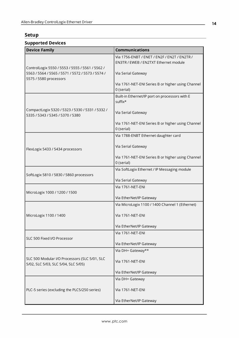
SetupSupported DevicesDevice Family Communications
ControlLogix 5550 / 5553 / 5555 / 5561 / 5562 /5563 / 5564 / 5565 / 5571 / 5572 / 5573 / 5574 /5575 / 5580 processors
Via 1756-ENBT / ENET / EN2F / EN2T / EN2TR /EN3TR / EWEB / EN2TXT Ethernet module
Via Serial Gateway
Via 1761-NET-ENI Series B or higher using Channel0 (serial)
CompactLogix 5320 / 5323 / 5330 / 5331 / 5332 /5335 / 5343 / 5345 / 5370 / 5380
Built-in Ethernet/IP port on processors with Esuffix*
Via Serial Gateway
Via 1761-NET-ENI Series B or higher using Channel0 (serial)
FlexLogix 5433 / 5434 processors
Via 1788-ENBT Ethernet daughter card
Via Serial Gateway
Via 1761-NET-ENI Series B or higher using Channel0 (serial)
SoftLogix 5810 / 5830 / 5860 processorsVia SoftLogix Ethernet / IP Messaging module
Via Serial Gateway
MicroLogix 1000 / 1200 / 1500Via 1761-NET-ENI
Via EtherNet/IP Gateway
MicroLogix 1100 / 1400
Via MicroLogix 1100 / 1400 Channel 1 (Ethernet)
Via 1761-NET-ENI
Via EtherNet/IP Gateway
SLC 500 Fixed I/O ProcessorVia 1761-NET-ENI
Via EtherNet/IP Gateway
SLC 500 Modular I/O Processors (SLC 5/01, SLC5/02, SLC 5/03, SLC 5/04, SLC 5/05)
Via DH+ Gateway**
Via 1761-NET-ENI
Via EtherNet/IP Gateway
PLC-5 series (excluding the PLC5/250 series)
Via DH+ Gateway
Via 1761-NET-ENI
Via EtherNet/IP Gateway
www.ptc.com
14
Allen-Bradley ControlLogix Ethernet Driver
Device Family Communications
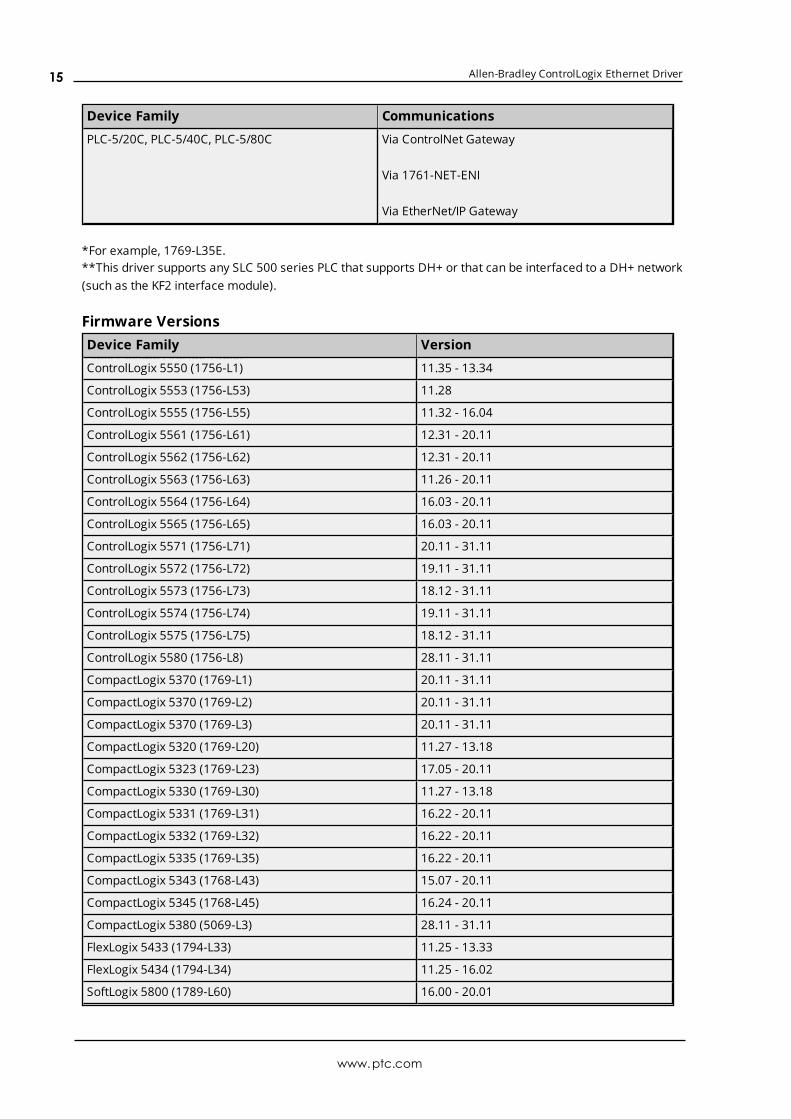
PLC-5/20C, PLC-5/40C, PLC-5/80C Via ControlNet Gateway
Via 1761-NET-ENI
Via EtherNet/IP Gateway
*For example, 1769-L35E.**This driver supports any SLC 500 series PLC that supports DH+ or that can be interfaced to a DH+ network(such as the KF2 interface module).
Firmware VersionsTable Column Outside Table:Table Column Outside Table:Device Family Version
ControlLogix 5550 (1756-L1) 11.35 - 13.34
ControlLogix 5553 (1756-L53) 11.28
ControlLogix 5555 (1756-L55) 11.32 - 16.04
ControlLogix 5561 (1756-L61) 12.31 - 20.11
ControlLogix 5562 (1756-L62) 12.31 - 20.11
ControlLogix 5563 (1756-L63) 11.26 - 20.11
ControlLogix 5564 (1756-L64) 16.03 - 20.11
ControlLogix 5565 (1756-L65) 16.03 - 20.11
ControlLogix 5571 (1756-L71) 20.11 - 31.11
ControlLogix 5572 (1756-L72) 19.11 - 31.11
ControlLogix 5573 (1756-L73) 18.12 - 31.11
ControlLogix 5574 (1756-L74) 19.11 - 31.11
ControlLogix 5575 (1756-L75) 18.12 - 31.11
ControlLogix 5580 (1756-L8) 28.11 - 31.11
CompactLogix 5370 (1769-L1) 20.11 - 31.11
CompactLogix 5370 (1769-L2) 20.11 - 31.11
CompactLogix 5370 (1769-L3) 20.11 - 31.11
CompactLogix 5320 (1769-L20) 11.27 - 13.18
CompactLogix 5323 (1769-L23) 17.05 - 20.11
CompactLogix 5330 (1769-L30) 11.27 - 13.18
CompactLogix 5331 (1769-L31) 16.22 - 20.11
CompactLogix 5332 (1769-L32) 16.22 - 20.11
CompactLogix 5335 (1769-L35) 16.22 - 20.11
CompactLogix 5343 (1768-L43) 15.07 - 20.11
CompactLogix 5345 (1768-L45) 16.24 - 20.11
CompactLogix 5380 (5069-L3) 28.11 - 31.11
FlexLogix 5433 (1794-L33) 11.25 - 13.33
FlexLogix 5434 (1794-L34) 11.25 - 16.02
SoftLogix 5800 (1789-L60) 16.00 - 20.01
www.ptc.com
15
Allen-Bradley ControlLogix Ethernet Driver
Table Column Outside Table:Table Column Outside Table:Device Family Version
ControlLogix, CompactLogix, and FlexLogix SerialCommunications
1761-NET-ENI Series B or higher or SerialGateway
MicroLogix 1100 (1763-L16AWA/BWA/BBB) 1.1
Communication ProtocolThe Communications Protocol is EtherNet/IP (CIP over Ethernet) using TCP/IP.
Logix and Gateway ModelsLogix and Gateway models support the following:
l Connected Messaging
l Symbolic Reads
l Symbolic Writes
l Symbol Instance Reads (V21 or higher)
l Physical (DMA) Reads (V20 or lower)
l Symbol Instance Writes
ENI ModelsENI models support unconnected messaging.
See Also:Channel SetupDevice Setup
Channel SetupThe maximum number of channels supported is 1024.
Channel setup includes configuration of the following property groups:GeneralEthernet CommunicationsWrite OptimizationsAdvanced
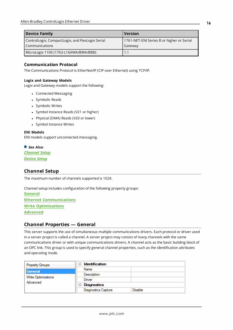
Channel Properties — GeneralThis server supports the use of simultaneous multiple communications drivers. Each protocol or driver usedin a server project is called a channel. A server project may consist of many channels with the samecommunications driver or with unique communications drivers. A channel acts as the basic building block ofan OPC link. This group is used to specify general channel properties, such as the identification attributesand operating mode.
www.ptc.com
16

Allen-Bradley ControlLogix Ethernet Driver
Identification
Name: User-defined identity of this channel. In each server project, each channel name must be unique.Although names can be up to 256 characters, some client applications have a limited display window whenbrowsing the OPC server's tag space. The channel name is part of the OPC browser information.For information on reserved characters, refer to "How To... Properly Name a Channel, Device, Tag, and Tag
Group" in the server help.
Description: User-defined information about this channel. Many of these properties, including Description, have an associated system tag.
Driver: Selected protocol / driver for this channel. This property specifies the device driver that was selectedduring channel creation. It is a disabled setting in the channel properties.
Note: With the server's online full-time operation, these properties can be changed at any time. Thisincludes changing the channel name to prevent clients from registering data with the server. If a client hasalready acquired an item from the server before the channel name is changed, the items are unaffected. If,after the channel name has been changed, the client application releases the item and attempts to re-acquire using the old channel name, the item is not accepted. With this in mind, changes to the propertiesshould not be made once a large client application has been developed. Utilize the User Manager to preventoperators from changing properties and restrict access rights to server features.
Diagnostics
Diagnostics Capture: When enabled, this option makes the channel's diagnostic information available toOPC applications. Because the server's diagnostic features require a minimal amount of overheadprocessing, it is recommended that they be utilized when needed and disabled when not. The default isdisabled.Note: This property is disabled if the driver does not support diagnostics.For more information, refer to "Communication Diagnostics" in the server help.
Channel Properties — Ethernet CommunicationsEthernet Communication can be used to communicate with devices.
Ethernet Settings
Network Adapter: Specify the network adapter to bind. When Default is selected, the operating systemselects the default adapter.
Channel Properties — Write OptimizationsAs with any OPC server, writing data to the device may be the application's most important aspect. Theserver intends to ensure that the data written from the client application gets to the device on time. Giventhis goal, the server provides optimization properties that can be used to meet specific needs or improveapplication responsiveness.
www.ptc.com
17

Allen-Bradley ControlLogix Ethernet Driver
Write Optimizations
Optimization Method: controls how write data is passed to the underlying communications driver. Theoptions are:
l Write All Values for All Tags: This option forces the server to attempt to write every value to thecontroller. In this mode, the server continues to gather write requests and add them to the server'sinternal write queue. The server processes the write queue and attempts to empty it by writing datato the device as quickly as possible. This mode ensures that everything written from the clientapplications is sent to the target device. This mode should be selected if the write operation order orthe write item's content must uniquely be seen at the target device.
l Write Only Latest Value for Non-Boolean Tags: Many consecutive writes to the same value canaccumulate in the write queue due to the time required to actually send the data to the device. If theserver updates a write value that has already been placed in the write queue, far fewer writes areneeded to reach the same final output value. In this way, no extra writes accumulate in the server'squeue. When the user stops moving the slide switch, the value in the device is at the correct value atvirtually the same time. As the mode states, any value that is not a Boolean value is updated in theserver's internal write queue and sent to the device at the next possible opportunity. This can greatlyimprove the application performance.
Note: This option does not attempt to optimize writes to Boolean values. It allows users tooptimize the operation of HMI data without causing problems with Boolean operations, such as amomentary push button.
l Write Only Latest Value for All Tags: This option takes the theory behind the second optimizationmode and applies it to all tags. It is especially useful if the application only needs to send the latestvalue to the device. This mode optimizes all writes by updating the tags currently in the write queuebefore they are sent. This is the default mode.
Duty Cycle: is used to control the ratio of write to read operations. The ratio is always based on one read forevery one to ten writes. The duty cycle is set to ten by default, meaning that ten writes occur for each readoperation. Although the application is performing a large number of continuous writes, it must be ensuredthat read data is still given time to process. A setting of one results in one read operation for every writeoperation. If there are no write operations to perform, reads are processed continuously. This allowsoptimization for applications with continuous writes versus a more balanced back and forth data flow.
Note: It is recommended that the application be characterized for compatibility with the writeoptimization enhancements before being used in a production environment.
Channel Properties — AdvancedThis group is used to specify advanced channel properties. Not all drivers support all properties; so theAdvanced group does not appear for those devices.
www.ptc.com
18

Allen-Bradley ControlLogix Ethernet Driver
Non-Normalized Float Handling: A non-normalized value is defined as Infinity, Not-a-Number (NaN), or asa Denormalized Number. The default is Replace with Zero. Drivers that have native float handling maydefault to Unmodified. Non-normalized float handling allows users to specify how a driver handles non-normalized IEEE-754 floating point data. Descriptions of the options are as follows:
l Replace with Zero: This option allows a driver to replace non-normalized IEEE-754 floating pointvalues with zero before being transferred to clients.
l Unmodified: This option allows a driver to transfer IEEE-754 denormalized, normalized, non-number, and infinity values to clients without any conversion or changes.
Note: This property is disabled if the driver does not support floating point values or if it only supports theoption that is displayed. According to the channel's float normalization setting, only real-time driver tags(such as values and arrays) are subject to float normalization. For example, EFM data is not affected by thissetting.
For more information on the floating point values, refer to "How To ... Work with Non-Normalized FloatingPoint Values" in the server help.
Inter-Device Delay: Specify the amount of time the communications channel waits to send new requests tothe next device after data is received from the current device on the same channel. Zero (0) disables thedelay.
Note: This property is not available for all drivers, models, and dependent settings.
www.ptc.com
19

Allen-Bradley ControlLogix Ethernet Driver
Device SetupDevice setup includes configuration of the following property groups:
General - IdentificationGeneral - Operating ModeScan ModeTimingAuto DemotionTag GenerationLogix Communications ParametersLogix OptionsLogix Database SettingsENI DF1/DH+/CN Gateway Communications ParametersRedundancy
Device Properties - Identification
Name: User-defined identity of this device.
Description: User-defined information about this device.
Channel Assignment: User-defined name of the channel to which this device currently belongs.
Driver: Selected protocol driver for this device.
Model: The specific version of the device.
ID: Enter the unique network address of the device, typically in the format of <IP or hostname>,1, <routingpath>,<slot>.
The conventions for addressing vary by model and routing. For more information, refer to the model-specificaddressing topics under Reference Material.
Device Properties — Operating Mode
www.ptc.com
20

Allen-Bradley ControlLogix Ethernet Driver
Data Collection: This property controls the device's active state. Although device communications areenabled by default, this property can be used to disable a physical device. Communications are notattempted when a device is disabled. From a client standpoint, the data is marked as invalid and writeoperations are not accepted. This property can be changed at any time through this property or the devicesystem tags.
Simulated: This option places the device into Simulation Mode. In this mode, the driver does not attempt tocommunicate with the physical device, but the server continues to return valid OPC data. Simulated stopsphysical communications with the device, but allows OPC data to be returned to the OPC client as valid data.While in Simulation Mode, the server treats all device data as reflective: whatever is written to the simulateddevice is read back and each OPC item is treated individually. The item's memory map is based on the groupUpdate Rate. The data is not saved if the server removes the item (such as when the server is reinitialized).The default is No.Notes:
1. This System tag (_Simulated) is read only and cannot be written to for runtime protection. The Systemtag allows this property to be monitored from the client.
2. In Simulation mode, the item's memory map is based on client update rate(s) (Group Update Rate forOPC clients or Scan Rate for native and DDE interfaces). This means that two clients that referencethe same item with different update rates return different data.
Simulation Mode is for test and simulation purposes only. It should never be used in a productionenvironment.
Device Properties — Scan ModeThe Scan Mode specifies the subscribed-client requested scan rate for tags that require devicecommunications. Synchronous and asynchronous device reads and writes are processed as soon aspossible; unaffected by the Scan Mode properties.
Scan Mode: specifies how tags in the device are scanned for updates sent to subscribing clients.Descriptions of the options are:
www.ptc.com
21

Allen-Bradley ControlLogix Ethernet Driver
l Respect Client-Specified Scan Rate: This mode uses the scan rate requested by the client.l Request Data No Faster than Scan Rate: This mode specifies the maximum scan rate to be used.
The valid range is 10 to 99999990 milliseconds. The default is 1000 milliseconds.Note: When the server has an active client and items for the device and the scan rate value is
increased, the changes take effect immediately. When the scan rate value is decreased, the changesdo not take effect until all client applications have been disconnected.
l Request All Data at Scan Rate: This mode forces tags to be scanned at the specified rate forsubscribed clients. The valid range is 10 to 99999990 milliseconds. The default is 1000 milliseconds.
l Do Not Scan, Demand Poll Only: This mode does not periodically poll tags that belong to thedevice nor perform a read to get an item's initial value once it becomes active. It is the client'sresponsibility to poll for updates, either by writing to the _DemandPoll tag or by issuing explicit devicereads for individual items. For more information, refer to "Device Demand Poll" in server help.
l Respect Tag-Specified Scan Rate: This mode forces static tags to be scanned at the rate specifiedin their static configuration tag properties. Dynamic tags are scanned at the client-specified scanrate.
Initial Updates from Cache: When enabled, this option allows the server to provide the first updates fornewly activated tag references from stored (cached) data. Cache updates can only be provided when thenew item reference shares the same address, scan rate, data type, client access, and scaling properties. Adevice read is used for the initial update for the first client reference only. The default is disabled; any time aclient activates a tag reference the server attempts to read the initial value from the device.
Device Properties — TimingThe device Timing properties allow the driver's response to error conditions to be tailored to fit theapplication's needs. In many cases, the environment requires changes to these properties for optimumperformance. Factors such as electrically generated noise, modem delays, and poor physical connectionscan influence how many errors or timeouts a communications driver encounters. Timing properties arespecific to each configured device.
Communications Timeouts
Connect Timeout: This property (which is used primarily by Ethernet based drivers) controls the amount oftime required to establish a socket connection to a remote device. The device's connection time often takeslonger than normal communications requests to that same device. The valid range is 1 to 30 seconds. Thedefault is typically 3 seconds, but can vary depending on the driver's specific nature. If this setting is notsupported by the driver, it is disabled.
Note: Due to the nature of UDP connections, the connection timeout setting is not applicable whencommunicating via UDP.
Request Timeout: This property specifies an interval used by all drivers to determine how long the driverwaits for a response from the target device to complete. The valid range is 50 to 9,999,999 milliseconds(167.6667 minutes). The default is usually 1000 milliseconds, but can vary depending on the driver. The
www.ptc.com
22
Allen-Bradley ControlLogix Ethernet Driver
default timeout for most serial drivers is based on a baud rate of 9600 baud or better. When using a driverat lower baud rates, increase the timeout to compensate for the increased time required to acquire data.
Attempts Before Timeout: This property specifies how many times the driver issues a communicationsrequest before considering the request to have failed and the device to be in error. The valid range is 1 to10. The default is typically 3, but can vary depending on the driver's specific nature. The number of attemptsconfigured for an application depends largely on the communications environment. This property applies toboth connection attempts and request attempts.
Timing
Inter-Request Delay: This property specifies how long the driver waits before sending the next request tothe target device. It overrides the normal polling frequency of tags associated with the device, as well asone-time reads and writes. This delay can be useful when dealing with devices with slow turnaround timesand in cases where network load is a concern. Configuring a delay for a device affects communications withall other devices on the channel. It is recommended that users separate any device that requires an inter-request delay to a separate channel if possible. Other communications properties (such as communicationserialization) can extend this delay. The valid range is 0 to 300,000 milliseconds; however, some drivers maylimit the maximum value due to a function of their particular design. The default is 0, which indicates nodelay between requests with the target device.
Note: Not all drivers support Inter-Request Delay. This setting does not appear if it is not available.
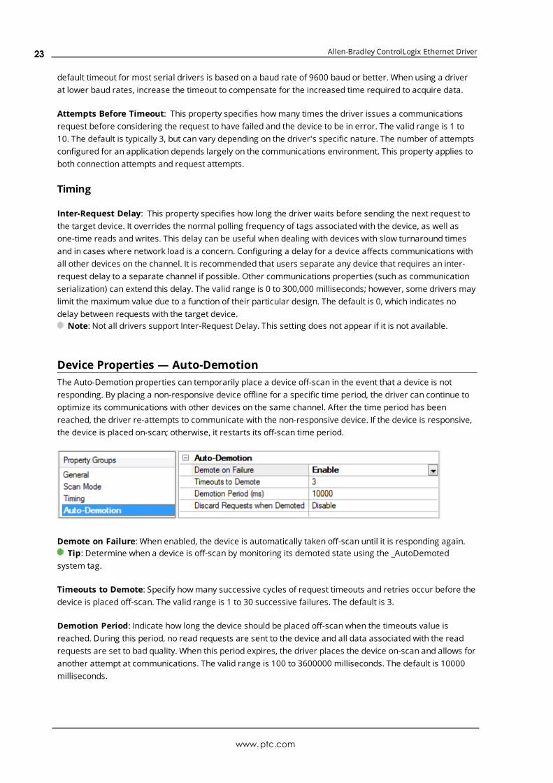
Device Properties — Auto-DemotionThe Auto-Demotion properties can temporarily place a device off-scan in the event that a device is notresponding. By placing a non-responsive device offline for a specific time period, the driver can continue tooptimize its communications with other devices on the same channel. After the time period has beenreached, the driver re-attempts to communicate with the non-responsive device. If the device is responsive,the device is placed on-scan; otherwise, it restarts its off-scan time period.
Demote on Failure: When enabled, the device is automatically taken off-scan until it is responding again.Tip: Determine when a device is off-scan by monitoring its demoted state using the _AutoDemoted
system tag.
Timeouts to Demote: Specify how many successive cycles of request timeouts and retries occur before thedevice is placed off-scan. The valid range is 1 to 30 successive failures. The default is 3.
Demotion Period: Indicate how long the device should be placed off-scan when the timeouts value isreached. During this period, no read requests are sent to the device and all data associated with the readrequests are set to bad quality. When this period expires, the driver places the device on-scan and allows foranother attempt at communications. The valid range is 100 to 3600000 milliseconds. The default is 10000milliseconds.
www.ptc.com
23
Allen-Bradley ControlLogix Ethernet Driver
Discard Requests when Demoted: Select whether or not write requests should be attempted during theoff-scan period. Disable to always send write requests regardless of the demotion period. Enable to discardwrites; the server automatically fails any write request received from a client and does not post a messageto the Event Log.
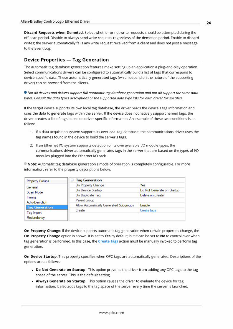
Device Properties — Tag GenerationThe automatic tag database generation features make setting up an application a plug-and-play operation.Select communications drivers can be configured to automatically build a list of tags that correspond todevice-specific data. These automatically generated tags (which depend on the nature of the supportingdriver) can be browsed from the clients.
Not all devices and drivers support full automatic tag database generation and not all support the same datatypes. Consult the data types descriptions or the supported data type lists for each driver for specifics.
If the target device supports its own local tag database, the driver reads the device's tag information anduses the data to generate tags within the server. If the device does not natively support named tags, thedriver creates a list of tags based on driver-specific information. An example of these two conditions is asfollows:
1. If a data acquisition system supports its own local tag database, the communications driver uses thetag names found in the device to build the server's tags.
2. If an Ethernet I/O system supports detection of its own available I/O module types, thecommunications driver automatically generates tags in the server that are based on the types of I/Omodules plugged into the Ethernet I/O rack.
Note: Automatic tag database generation's mode of operation is completely configurable. For moreinformation, refer to the property descriptions below.
On Property Change: If the device supports automatic tag generation when certain properties change, theOn Property Change option is shown. It is set to Yes by default, but it can be set to No to control over whentag generation is performed. In this case, the Create tags action must be manually invoked to perform taggeneration.
On Device Startup: This property specifies when OPC tags are automatically generated. Descriptions of theoptions are as follows:
l Do Not Generate on Startup: This option prevents the driver from adding any OPC tags to the tagspace of the server. This is the default setting.
l Always Generate on Startup: This option causes the driver to evaluate the device for taginformation. It also adds tags to the tag space of the server every time the server is launched.
www.ptc.com
24
Allen-Bradley ControlLogix Ethernet Driver
l Generate on First Startup: This option causes the driver to evaluate the target device for taginformation the first time the project is run. It also adds any OPC tags to the server tag space asneeded.
Note: When the option to automatically generate OPC tags is selected, any tags that are added to theserver's tag space must be saved with the project. Users can configure the project to automatically savefrom the Tools | Options menu.
On Duplicate Tag: When automatic tag database generation is enabled, the server needs to know what todo with the tags that it may have previously added or with tags that have been added or modified after thecommunications driver since their original creation. This setting controls how the server handles OPC tagsthat were automatically generated and currently exist in the project. It also prevents automaticallygenerated tags from accumulating in the server.
For example, if a user changes the I/O modules in the rack with the server configured to Always Generateon Startup, new tags would be added to the server every time the communications driver detected a newI/O module. If the old tags were not removed, many unused tags could accumulate in the server's tag space.The options are:
l Delete on Create: This option deletes any tags that were previously added to the tag space beforeany new tags are added. This is the default setting.
l Overwrite as Necessary: This option instructs the server to only remove the tags that thecommunications driver is replacing with new tags. Any tags that are not being overwritten remain inthe server's tag space.
l Do not Overwrite: This option prevents the server from removing any tags that were previouslygenerated or already existed in the server. The communications driver can only add tags that arecompletely new.
l Do not Overwrite, Log Error: This option has the same effect as the prior option, and also posts anerror message to the server's Event Log when a tag overwrite would have occurred.
Note: Removing OPC tags affects tags that have been automatically generated by thecommunications driver as well as any tags that have been added using names that match generatedtags. Users should avoid adding tags to the server using names that may match tags that areautomatically generated by the driver.
Parent Group: This property keeps automatically generated tags from mixing with tags that have beenentered manually by specifying a group to be used for automatically generated tags. The name of the groupcan be up to 256 characters. This parent group provides a root branch to which all automatically generatedtags are added.
Allow Automatically Generated Subgroups: This property controls whether the server automaticallycreates subgroups for the automatically generated tags. This is the default setting. If disabled, the servergenerates the device's tags in a flat list without any grouping. In the server project, the resulting tags arenamed with the address value. For example, the tag names are not retained during the generation process.
Note: If, as the server is generating tags, a tag is assigned the same name as an existing tag, the systemautomatically increments to the next highest number so that the tag name is not duplicated. For example, ifthe generation process creates a tag named "AI22" that already exists, it creates the tag as "AI23" instead.
Create: Initiates the creation of automatically generated OPC tags. If the device's configuration has beenmodified, Create tags forces the driver to reevaluate the device for possible tag changes. Its ability to beaccessed from the System tags allows a client application to initiate tag database creation.
www.ptc.com
25

Allen-Bradley ControlLogix Ethernet Driver
Note: Create tags is disabled if the Configuration edits a project offline.
Device Properties — Logix Communications Parameters
EtherNet/IP
TCP/IP Port: Specifies the TCP/IP port number that the device is configured to use. The default is 44818.
CIP
Connection Size: Specify the number of bytes available on the CIP connection for data requests andresponses. The valid range is 500 to 4000 bytes. The default is 500 bytes.Note: Only the ControlLogix 5500 and CompactLogix 5300 device models support this feature. To support
connection sizes greater than 500 bytes, the device must support Firmware version 20 or later controllersand Ethernet bridge EN3x, EN2x, or EN5.x. Older Ethernet modules like ENBT and ENET do not support thisfeature. Devices that do not meet the necessary requirements automatically fall back to the default settingof 500 bytes, although the requested size is re-attempted after communications failure.
The Connection Size value may also be requested through the System tag "_CIPConnectionSizeRequested." Formore information, refer to Internal Tags.
Inactivity Watchdog: Specify the amount of time, in seconds, a connection remains idle (without read/writetransactions) before being closed by the controller. The larger the value, the more time it takes forconnection resources to be released by the controller and vice versa. The default is 32 seconds.Note: If an error about the CIP connection timing out while uploading a project occurs frequently, increase
the Inactivity Watchdog value. Otherwise, the default value is suggested.
Logix
Array Block Size: This property specifies the maximum number of array elements to read in a singletransaction. The value is adjustable and ranges from 30 to 3840 elements. The default is 120 elements.
Tip: For Boolean arrays, a single element is considered a 32-element bit array. Setting the block size to 30elements translates to 960 bit elements, whereas 3840 elements translate to 122880 bit elements.
Device Properties — Logix Options
www.ptc.com
26
Allen-Bradley ControlLogix Ethernet Driver
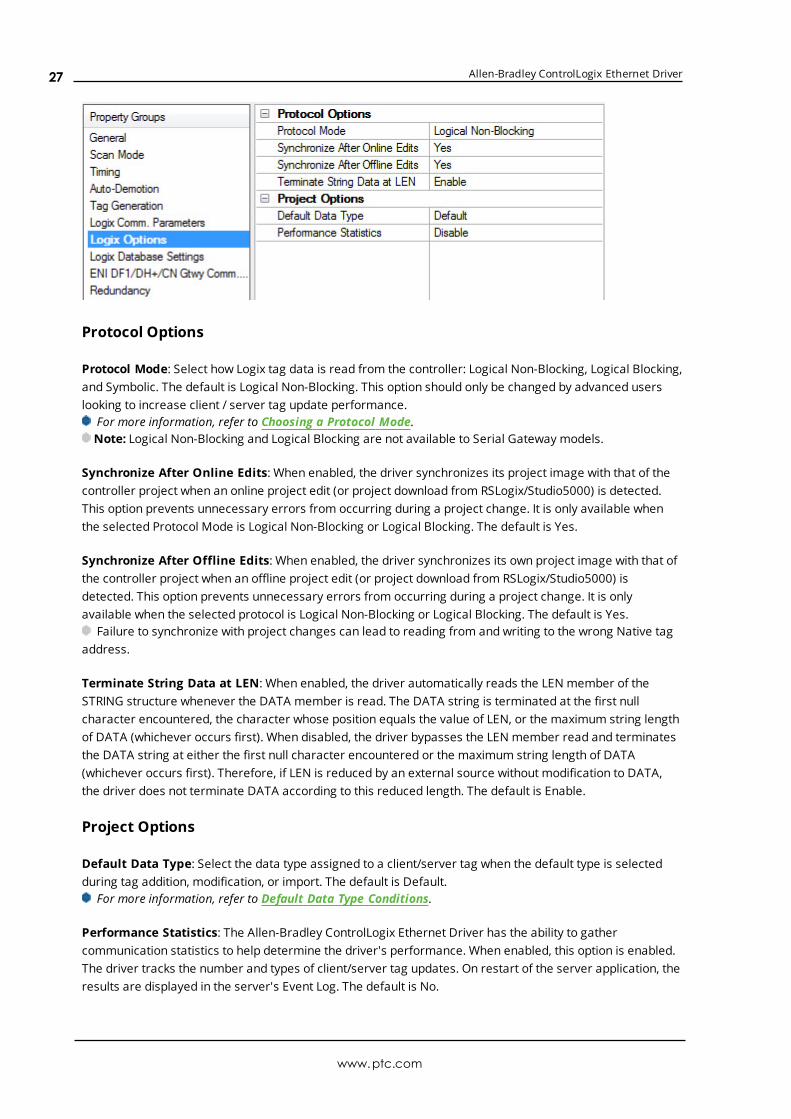
Protocol Options
Protocol Mode: Select how Logix tag data is read from the controller: Logical Non-Blocking, Logical Blocking,and Symbolic. The default is Logical Non-Blocking. This option should only be changed by advanced userslooking to increase client / server tag update performance.
For more information, refer to Choosing a Protocol Mode.Note: Logical Non-Blocking and Logical Blocking are not available to Serial Gateway models.
Synchronize After Online Edits: When enabled, the driver synchronizes its project image with that of thecontroller project when an online project edit (or project download from RSLogix/Studio5000) is detected.This option prevents unnecessary errors from occurring during a project change. It is only available whenthe selected Protocol Mode is Logical Non-Blocking or Logical Blocking. The default is Yes.
Synchronize After Offline Edits: When enabled, the driver synchronizes its own project image with that ofthe controller project when an offline project edit (or project download from RSLogix/Studio5000) isdetected. This option prevents unnecessary errors from occurring during a project change. It is onlyavailable when the selected protocol is Logical Non-Blocking or Logical Blocking. The default is Yes.
Failure to synchronize with project changes can lead to reading from and writing to the wrong Native tagaddress.
Terminate String Data at LEN: When enabled, the driver automatically reads the LEN member of theSTRING structure whenever the DATA member is read. The DATA string is terminated at the first nullcharacter encountered, the character whose position equals the value of LEN, or the maximum string lengthof DATA (whichever occurs first). When disabled, the driver bypasses the LEN member read and terminatesthe DATA string at either the first null character encountered or the maximum string length of DATA(whichever occurs first). Therefore, if LEN is reduced by an external source without modification to DATA,the driver does not terminate DATA according to this reduced length. The default is Enable.
Project Options
Default Data Type: Select the data type assigned to a client/server tag when the default type is selectedduring tag addition, modification, or import. The default is Default.
For more information, refer to Default Data Type Conditions.
Performance Statistics: The Allen-Bradley ControlLogix Ethernet Driver has the ability to gathercommunication statistics to help determine the driver's performance. When enabled, this option is enabled.The driver tracks the number and types of client/server tag updates. On restart of the server application, theresults are displayed in the server's Event Log. The default is No.
www.ptc.com
27

Allen-Bradley ControlLogix Ethernet Driver
Note: Once a project configuration is designed for optimal performance, it is recommended that usersdisable Performance Statistics. Because the statistics are written to the Event Log on shutdown, the servermust be re-launched to view the results.
See Also: Detecting a Change in the Controller Project
Device Properties — Logix Database Settings
Database Import Method
Database Import Method: Select how the tag database should be populated:
l Create from Device: retrieves tags directly from the controller over the same Ethernet connectionthat is used for data access, which is fast and imports most tags, but requires access to thecontroller and does not import descriptions. Tags that are not imported include Add-On Instruction(AOI) InOut properties.Note: This feature is not available to Serial Gateway models.
l Create from Import File: retrieves tags from a selected RSLogix L5K/L5X file. Controller access isnot necessary, descriptions are imported, and users can work offline; however, this option is slowerand does not import all the tags in the controller. Tags that are not imported include:
l I/O tags
l Add-On Instruction (AOI) InOut properties
l AOI properties that alias other properties
l Equipment Phase properties that alias properties from another Equipment Phase orProgram
l Program properties that alias properties from another Program or Equipment Phase
l Timer/Counter CTL bits
Tag Import File: Click the browse (...) button to locate and select the L5K/L5X file from which tags are to beimported. This file is used when Automatic Tag Database Generation is instructed to create the tagdatabase. All tags, including Global and Program, are imported and expanded according to their respectivedata types.
Tag Descriptions: Choose Enable to import tag descriptions for non-structure, non-array tags. If necessary,a description is given to tags with long names stating the original tag name.
Logix Database Options
www.ptc.com
28

Allen-Bradley ControlLogix Ethernet Driver
Limit Name Length: Select Enable to constrain the tag and group names to 31 characters. The default isDisable.
1. Before OPC server version 4.70, tag and group name lengths were restricted to 31 characters. Thecurrent length restriction of 256 characters can fit Logix 40-character Logix Tag names.
2. If an older server version was used to import tags via L5K/L5X import, inspect the Event Log or scanthe server project to see if any tags were truncated due to the character limit. If so, Enable thisproperty to preserve the server tag names. OPC client tag references are not affected. If disabled,longer tag names are created and clients referencing the clipped tag must be changed to referencethe new tag name.
3. If an older OPC server version was used to import tags via L5K/L5X import and no tags weretruncated due to the 31-character limit, leave this options disabled.
4. If tags were imported via L5K/L5X with server version 4.70 or above, leave this options disabled.See Also: Controller-to-Server Name Conversions
Tag Hierarchy: This property specifies the tree organization of the tag hierarchy. When Condensed, theserver tags created by automatic tag generation follow a group/tag hierarchy consistent with the tag'saddress. Groups are created for every segment preceding the period. When Expanded, the server tagscreated by automatic tag generation follow a group/tag hierarchy consistent with the tag hierarchy inRSLogix 5000. Groups are created for every segment preceding the period and to represent logicalgroupings. To use this functionality, enable Allow Sub Groups in Tag Generation properties.For more information on the groups created, refer to Tag Hierarchy and Controller-to-Server Name
Conversions.
Logix Database Filtering
Impose Array Limit: Select Enable to constrain the number of array elements. Tags in the controller can bedeclared with very large array dimensions. By default, arrays are completely expanded during the taggeneration process, which becomes time consuming for large arrays. By imposing a limit, only a specifiednumber of elements from each dimension are generated. Limits only takes effect when the array dimensionsize exceeds the limit. The default is Disable.
Array Count Upper Limit: Specify the array count limit. The default is 2000.
Device Properties — ENI DF1/DH+/CN Gateway CommunicationsParameters
TCP/IP Port: Specify the port number that the remote device is configured to use (such as 1756-ENBT). Thedefault is 44818.
Request Size: Select the number of bytes that may be requested from a device at one time to refineperformance. Options are 32, 64, 128, or 232. The default is 232 bytes.
www.ptc.com
29
Allen-Bradley ControlLogix Ethernet Driver
Allow Function File Block Writes: Function files are structure-based files (much like PD and MG data files)and are unique to the MicroLogix 1100, 1200, and 1500. For applicable function files, data can be written tothe device in a single operation. By default, when data is written to a function file sub element (field withinthe function file structure), a write operation occurs immediately for that tag. For such files as the RTC file,whose sub elements include hour (HR), minute (MIN), and second (SEC), individual writes are not alwaysacceptable. With such sub elements relying solely on time, values must be written in one operation to avoidtime elapsing between sub elements writes. For this reason, there is the option to block write these subelements. The default is disabled.
For more information, refer to Block Writes and Function Files.
Block WritesBlock writing involves writing to the device the values of every read/write sub element in the function file in asingle write operation. It is not necessary to write to every sub element before performing a block write. Subelements that are not affected (written to) have their current value written back to them. For example, if thecurrent (last read) date and time is 1/1/2001, 12:00.00, DOW = 3 and the hour is changed to 1 o'clock, thevalues written to the device are 1/1/2001, 1:00.00, DOW = 3. For more information, refer to the instructionsbelow.
1. To start, locate ENI DF1/DH+/CN Gateway Communications Parameters in Device Properties.
2. Enable Allow Function Files Block Writes to notify the driver to utilize block writes on function filesthat support block writes.
3. Clicking OK or Apply.
4. Write the desired value to the sub element tag in question. The sub element tag immediately takeson the value written to it.
Note: After a sub element is written to at least once in block write mode, the tag's value does notoriginate from the controller, but instead from the driver's write cache. After the block write is done,all sub element tag values originate from the controller.
5. Once the entire desired sub elements are written, perform the block write that sends these values tothe controller. To instantiate a block write, reference tag address RTC:<element>._SET. Setting thistag's value to 'true' causes a block write to occur based on the current (last read) sub elements andthe sub elements affected (written to). Immediately after setting the tag to 'true', it is automaticallyreset to "false." This is the default state and performs no action.
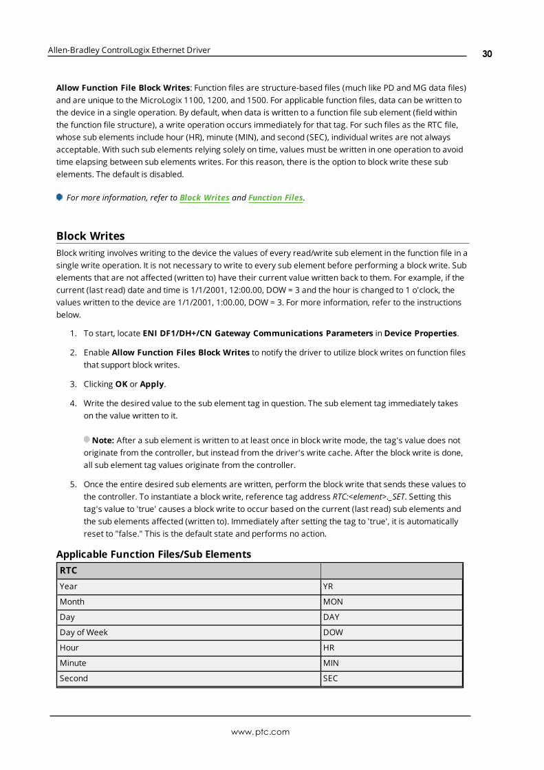
Applicable Function Files/Sub ElementsRTC
Year YR
Month MON
Day DAY
Day of Week DOW
Hour HR
Minute MIN
Second SEC
www.ptc.com
30
Allen-Bradley ControlLogix Ethernet Driver
See Also: Function File Listing
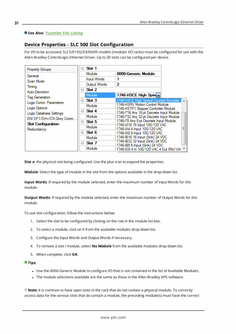
Device Properties - SLC 500 Slot ConfigurationFor I/O to be accessed, SLC5/01/02/03/04/05 models (modular I/O racks) must be configured for use with theAllen-Bradley ControlLogix Ethernet Driver. Up to 30 slots can be configured per device.
Slot n: the physical slot being configured. Use the plus icon to expand the properties.
Module: Select the type of module in the slot from the options available in the drop-down list.
Input Words: If required by the module selected, enter the maximum number of Input Words for thismodule.
Output Words: If required by the module selected, enter the maximum number of Output Words for thismodule.
To use slot configuration, follow the instructions below:
1. Select the slot to be configured by clicking on the row in the module list box.
2. To select a module, click on it from the available modules drop-down list.
3. Configure the Input Words and Output Words if necessary.
4. To remove a slot / module, select No Module from the available modules drop-down list.
5. When complete, click OK.
Tips:
l Use the 0000-Generic Module to configure I/O that is not contained in the list of Available Modules.
l The module selections available are the same as those in the Allen Bradley APS software.
Note: It is common to have open slots in the rack that do not contain a physical module. To correctlyaccess data for the various slots that do contain a module, the preceding module(s) must have the correct
www.ptc.com
31
Allen-Bradley ControlLogix Ethernet Driver
number of words mapped. For example, if only interested in the I/O in slot 3, but slots 1 and 2 contain I/Omodules, the correct modules must be selected for slots 1, 2, and 3 from this slot configuration group.
0000-Generic ModuleUse the Generic Module to map Input and Output words for modules that are not represented in the list ofavailable modules. To correctly use the Generic Module, users must know the number of Input and Outputwords required for each module.
Consult Allen-Bradley I/O user manual documentation to confirm Input and Output requirements and beaware that requirements may be different based on Class 1 or Class 3 operation.For information on the number of input and output words available for each I/O module, refer to Modular
I/O Selection Guide.
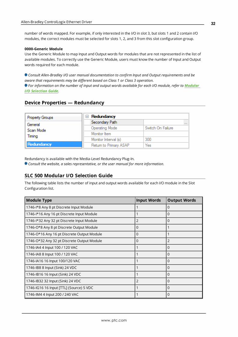
Device Properties — Redundancy
Redundancy is available with the Media-Level Redundancy Plug-In.Consult the website, a sales representative, or the user manual for more information.
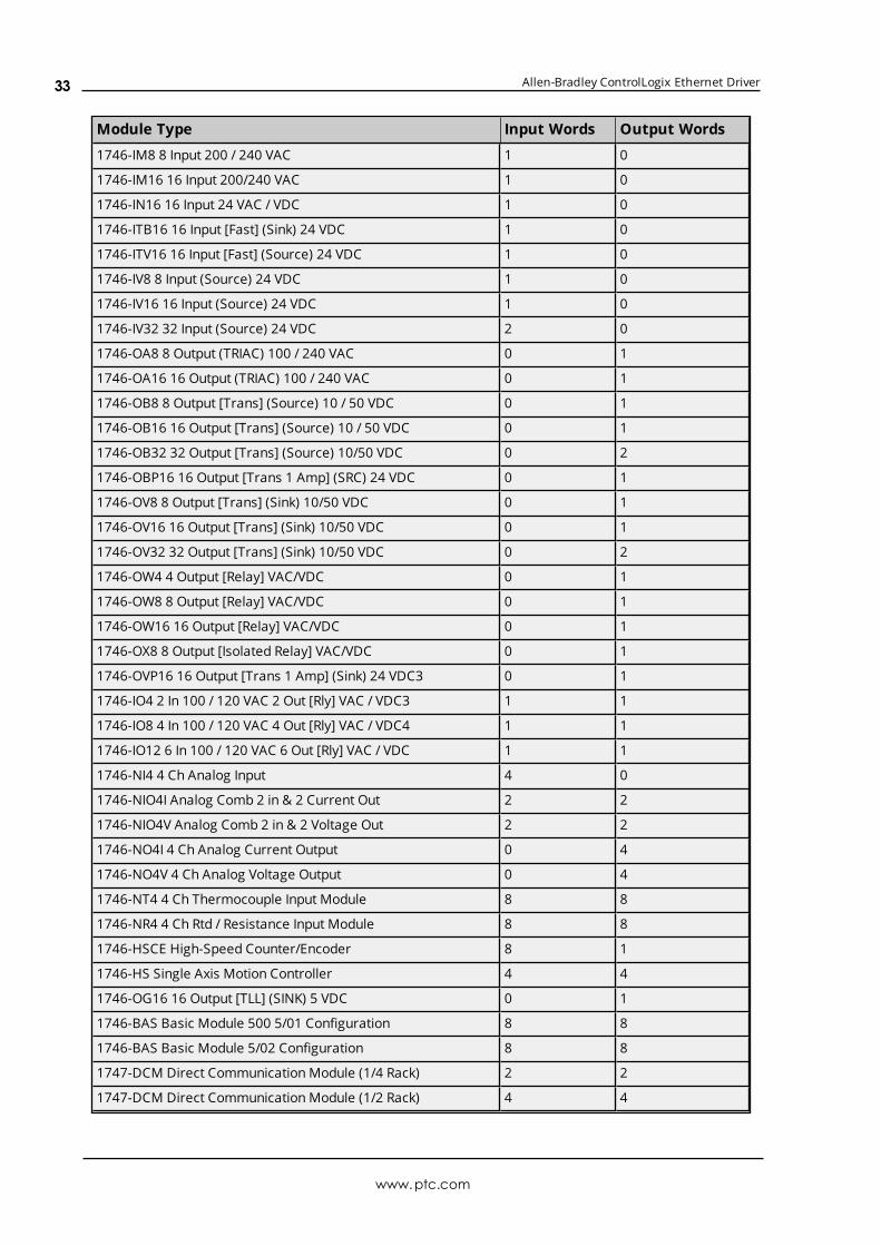
SLC 500 Modular I/O Selection GuideThe following table lists the number of input and output words available for each I/O module in the SlotConfiguration list.
Module Type Input Words Output Words
1746-I*8 Any 8 pt Discrete Input Module 1 0
1746-I*16 Any 16 pt Discrete Input Module 1 0
1746-I*32 Any 32 pt Discrete Input Module 2 0
1746-O*8 Any 8 pt Discrete Output Module 0 1
1746-O*16 Any 16 pt Discrete Output Module 0 1
1746-O*32 Any 32 pt Discrete Output Module 0 2
1746-IA4 4 Input 100 / 120 VAC 1 0
1746-IA8 8 Input 100 / 120 VAC 1 0
1746-IA16 16 Input 100/120 VAC 1 0
1746-IB8 8 Input (Sink) 24 VDC 1 0
1746-IB16 16 Input (Sink) 24 VDC 1 0
1746-IB32 32 Input (Sink) 24 VDC 2 0
1746-IG16 16 Input [TTL] (Source) 5 VDC 1 0
1746-IM4 4 Input 200 / 240 VAC 1 0
www.ptc.com
32
Allen-Bradley ControlLogix Ethernet Driver
Module Type Input Words Output Words
1746-IM8 8 Input 200 / 240 VAC 1 0
1746-IM16 16 Input 200/240 VAC 1 0
1746-IN16 16 Input 24 VAC / VDC 1 0
1746-ITB16 16 Input [Fast] (Sink) 24 VDC 1 0
1746-ITV16 16 Input [Fast] (Source) 24 VDC 1 0
1746-IV8 8 Input (Source) 24 VDC 1 0
1746-IV16 16 Input (Source) 24 VDC 1 0
1746-IV32 32 Input (Source) 24 VDC 2 0
1746-OA8 8 Output (TRIAC) 100 / 240 VAC 0 1
1746-OA16 16 Output (TRIAC) 100 / 240 VAC 0 1
1746-OB8 8 Output [Trans] (Source) 10 / 50 VDC 0 1
1746-OB16 16 Output [Trans] (Source) 10 / 50 VDC 0 1
1746-OB32 32 Output [Trans] (Source) 10/50 VDC 0 2
1746-OBP16 16 Output [Trans 1 Amp] (SRC) 24 VDC 0 1
1746-OV8 8 Output [Trans] (Sink) 10/50 VDC 0 1
1746-OV16 16 Output [Trans] (Sink) 10/50 VDC 0 1
1746-OV32 32 Output [Trans] (Sink) 10/50 VDC 0 2
1746-OW4 4 Output [Relay] VAC/VDC 0 1
1746-OW8 8 Output [Relay] VAC/VDC 0 1
1746-OW16 16 Output [Relay] VAC/VDC 0 1
1746-OX8 8 Output [Isolated Relay] VAC/VDC 0 1
1746-OVP16 16 Output [Trans 1 Amp] (Sink) 24 VDC3 0 1
1746-IO4 2 In 100 / 120 VAC 2 Out [Rly] VAC / VDC3 1 1
1746-IO8 4 In 100 / 120 VAC 4 Out [Rly] VAC / VDC4 1 1
1746-IO12 6 In 100 / 120 VAC 6 Out [Rly] VAC / VDC 1 1
1746-NI4 4 Ch Analog Input 4 0
1746-NIO4I Analog Comb 2 in & 2 Current Out 2 2
1746-NIO4V Analog Comb 2 in & 2 Voltage Out 2 2
1746-NO4I 4 Ch Analog Current Output 0 4
1746-NO4V 4 Ch Analog Voltage Output 0 4
1746-NT4 4 Ch Thermocouple Input Module 8 8
1746-NR4 4 Ch Rtd / Resistance Input Module 8 8
1746-HSCE High-Speed Counter/Encoder 8 1
1746-HS Single Axis Motion Controller 4 4
1746-OG16 16 Output [TLL] (SINK) 5 VDC 0 1
1746-BAS Basic Module 500 5/01 Configuration 8 8
1746-BAS Basic Module 5/02 Configuration 8 8
1747-DCM Direct Communication Module (1/4 Rack) 2 2
1747-DCM Direct Communication Module (1/2 Rack) 4 4
www.ptc.com
33

Allen-Bradley ControlLogix Ethernet Driver
Module Type Input Words Output Words
1747-DCM Direct Communication Module (3/4 Rack) 6 6
1747-DCM Direct Communication Module (Full Rack) 8 8
1747-SN Remote I/O Scanner 32 32
1747-DSN Distributed I/O Scanner 7 Blocks 8 8
1747-DSN Distributed I/O Scanner 30 Blocks 32 32
1747-KE Interface Module, Series A 1 0
1747-KE Interface Module, Series B 8 8
1746-NI8 8 Ch Analog Input, Class 1 8 8
1746-NI8 8 Ch Analog Input, Class 3 16 12
1746-IC16 16 Input (Sink) 48 VDC 1 0
1746-IH16 16 Input [Trans] (Sink) 125 VDC 1 0
1746-OAP12 12 Output [Triac] 120/240 VDC 0 1
1746-OB6EI 6 Output [Trans] (Source) 24 VDC 0 1
1746-OB16E 16 Output [Trans] (Source) Protected 0 1
1746-OB32E 32 Output [Trans] (Source) 10 / 50 VDC 0 2
1746-OBP8 8 Output [Trans 2 amp] (Source) 24 VDC 0 1
1746-IO12DC 6 Input 12 VDC, 6 Output [Rly] 1 1
1746-INI4I Analog 4 Ch. Isol. Current Input 8 8
1746-INI4VI Analog 4 Ch. Isol. Volt/Current Input 8 8
1746-INT4 4 Ch. Isolated Thermocouple Input 8 8
1746-NT8 Analog 8 Ch Thermocouple Input 8 8
1746-HSRV Motion Control Module 12 8
1746-HSTP1 Stepper Controller Module 8 8
1747-MNET MNET Network Comm Module 0 0
1746-QS Synchronized Axes Module 32 32
1747-QV Open Loop Velocity Control 8 8
1747-RCIF Robot Control Interface Module 32 32
1747-SCNR ControlNet SLC Scanner 32 32
1747-SDN DeviceNet Scanner Module 32 32
1394-SJT GMC Turbo System 32 32
1203-SM1 SCANport Comm Module - Basic 8 8
1203-SM1 SCANport Comm Module - Enhanced 32 32
AMCI-1561 AMCI Series 1561 Resolver Module 8 8
www.ptc.com
34
Allen-Bradley ControlLogix Ethernet Driver
Performance OptimizationsFor more information on optimization at the communication and application levels, select a link from the listbelow.
Optimizing CommunicationsOptimizing ApplicationPerformance Statistics and TuningPerformance Tuning Example
Optimizing CommunicationsAs with any programmable controller, there are a variety of ways to enhance the performance and systemcommunications.
Protocol ModeThe Protocol Mode determines how Logix tag data is accessed from the controller. There are three types ofprotocol modes: Symbolic, Logical Non-Blocking and Logical Blocking. Descriptions are as follows:
l Symbolic Mode: Each client/server tag address is represented in the packet by its ASCII charactername.
l Logical Non-Blocking Mode: Each client/server tag is represented by its logical memory address inthe PLC.
l Logical Blocking Mode: The Logix tag is accessed as a single chunk of data. Each client/server tag(such as MYTIMER.ACC) has a corresponding Logix tag (MYTIMER). Many client/server tags canbelong to the same Logix tag, as in the case of structures. On every read cycle, the Logix tag is read,its block is updated in the driver cache and all client/server tags are updated from this cache.
Logical Non-Blocking Mode is generally recommended because it is the most efficient mode for gatheringand processing Logix tag data. Symbolic Mode is recommended for backward compatibility, whereas LogicalNon-Blocking Mode is recommended for projects containing a small number of references to UDT and/orpredefined structure Logix tags. Although Logical Blocking Mode can be efficient, it can also hurtperformance if used incorrectly. For more information on each mode's benefits and detriments, refer toChoosing a Protocol Mode.
Tag Division TipsUsers should designate one or more devices for Logical Blocking purposes and one or more devices forLogical Non-Blocking purposes. This improves performance because different tags in a project are oftenbetter suited for different modes. When utilizing tag division, users should do the following:
1. Assign server tags referencing Atomic Logix tags (array or non-array) to the Logical Non-Blockingdevice.
2. Assign server tags referencing a Structure Logix tag composed of one-third* or less of the Structuretag to the Logical Non-Blocking device(s). For example, if there are 55** or less member tagsreferencing a PID_ENHANCED Logix tag, all these tags should be assigned to the Logical Non-Blocking device.
3. Assign server tags referencing a Structure Logix tag composed of one-third* or more of theStructure tag to the Logical Blocking device(s). For example, if there are more than 55** membertags referencing a PID_ENHANCED Logix tag, all of those tags should be assigned to the LogicalBlocking device.
*One-third is not an exact limit, but rather a figure that has held true in a number of studies.
www.ptc.com
35

Allen-Bradley ControlLogix Ethernet Driver
**A PID_ENHANCED structure has 165 tags, so one-third equals 55 tags.
Connection SizeIncreasing the Connection Size allows more read/write requests per data packet, which provides greaterthroughput. Although it also increases the CPU load and response turnaround time, it significantly improvesperformance. The Connection Size property may be modified in the ControlLogix 5500 and CompactLogix5300 device models only. For more information, refer to Logix Communications Parameters.
UDT Substructure AliasingIf a UDT contains large substructures and one-third or more of the substructure members are referenced inthe client, refer to the following instructions to optimize reads for the substructure.
1. Create an alias of the substructure in RSLogix 5000. Then, assign server tags referencing the rest ofthe UDT substructure to a Logical Blocking device.
2. Next, assign the server tags referencing the rest of the UDT (but not the substructure) to a LogicalNon-Blocking device.
System Overhead Time SliceThe System Overhead Time Slice (SOTS) is the percentage of time allocated to perform communicationtasks (such as OPC driver communications) that is set in RSLogix 5000. 100% SOTS is the percentage of timefor controller tasks (such as ladder logic). The default SOTS is 10%. In every 10 ms program scan thatoccurs, the controller spends 1 ms processing driver requests (if the controller has a continuous task). Thevalue of SOTS defines the task's priority. If controller tasks are a high priority, the SOTS should be set below30%. If the communication tasks are high priority, the SOTS should be set at or above 30%. For the bestbalance of communications performance and CPU utilization, set the SOTS to 10% to 40%.
Multi-Request PacketsThe Allen-Bradley ControlLogix Ethernet Driver has been designed to optimize reads and writes. For non-array, non-string tags (which only request one element), requests are blocked into a single transaction. Thisprovides drastic improvement in performance over single tag transactions. The only limitation is the numberof data bytes that can fit in a single transaction.
Important: In Symbolic Mode, each tag's ASCII string value is inserted into the request packet until nomore tag requests fit. For optimum performance, users should keep the tag names' size to a minimum. Thesmaller the tag name, the more tags that fit in a single transaction and the fewer transactions needed toprocess all tags.
Array Elements Blocked (Symbolic and Logical Non-Blocking Modes Only)To optimize the reading of atomic array elements, read a block of the array in a single request instead ofindividually. The more elements read in a block, the greater the performance. Since transaction overheadand processing consumes the most time, do as few transactions as possible while scanning as many desiredtags as possible. This is the essence of array element blocking.
Block sizes are specified as an element count. A block size of 120 elements means that a maximum of 120array elements are read in one request. The maximum block size is 3840 elements. Boolean arrays aretreated differently: in protocol, a Boolean array is a 32-bit array. Thus, requesting element 0 is requestingbits 0 through 31. To maintain consistency in discussion, a Boolean array element is considered a single bit.In summary, the maximum number of array elements (based on block size of 3840) that can be requested isas follows: 122880 BOOL, 3840 SINT, 3840 INT, 3840 DINT and 3840 REAL.
www.ptc.com
36

Allen-Bradley ControlLogix Ethernet Driver
As discussed in Logix Communication Parameters, the block size is adjustable and should be chosenbased on the project at hand. For example, if array elements 0-26 and element 3839 are tags to be read,then using a block size of 3840 is not only overkill, but detrimental to the driver's performance. This isbecause all elements between 0 and 3839 are read on each request, even though only 28 of those elementsare of importance. In this case, a block size of 30 is more appropriate. Elements 0-26 would be serviced inone request and element 3839 would be serviced on the next.
Optimizing StringsIn the Logical Addressing modes, a write to STRING.DATA also writes to STRING.LEN with the proper lengthvalue.
Terminate String Data at LENIn this driver, string tags are structures with separate character data and length components. As such, thedriver automatically reads a string tag in two transactions: one in Logical Protocol Mode for the stringcharacter data (DATA) and one in Symbolic Mode for the string length (LEN). When the Terminate StringData at LEN option is disabled, a single transaction is made to read the string character data. In this case,the Symbolic Mode read for string length is bypassed. In a project with many string tags, this cansignificantly reduce the time required to read all tags.
For more information on the Terminate String Data at LEN option, refer to Logix Options.
Optimizing the ApplicationThe Allen-Bradley ControlLogix Ethernet Driver has been designed to provide the best performance with theleast amount of impact on the system's overall performance. While the Allen-Bradley ControlLogix EthernetDriver is fast, there are a couple of guidelines that can be used to optimize the application and gainmaximum performance.
The server refers to communications protocols like Allen-Bradley ControlLogix Ethernet as a channel. Eachchannel defined in the application represents a separate path of execution in the server. Once a channel hasbeen defined, a series of devices must then be defined under that channel. Each of these devices representsa single Allen-Bradley Logix CPU from which data is collected. While this approach to defining the applicationprovides a high level of performance, it doesn't take full advantage of the Allen-Bradley ControlLogixEthernet Driver or the network. An example of how the application may appear when configured using asingle channel is shown below.
Each device appears under a single channel, called "CLEthernet_Channel1". In thisconfiguration, the driver moves from one device to the next as quickly as possible togather information at an effective rate. As more devices are added or moreinformation is requested from a single device, the overall update rate begins to suffer.
If the driver could only define a single channel, the example above would be the only option available;however, the driver can define up to 1024 channels. Using multiple channels distributes the data collectionworkload by simultaneously issuing multiple requests to the network. An example of how the sameapplication may appear when configured using multiple channels to improve performance is shown below.
www.ptc.com
37

Allen-Bradley ControlLogix Ethernet Driver
Each device has now been defined under its own channel. In this new configuration, asingle path of execution is dedicated to the task of gathering data from each device. Ifthe application has fewer devices, it can be optimized as shown here.
The performance improves even if the application has more devices. While fewerdevices may be ideal, the application still benefits from additional channels. Althoughby spreading the device load across all channels causes the server to move fromdevice to device again, it can now do so with far less devices to process on a singlechannel.
Performance Statistics and TuningThe Performance Statistics feature provides benchmarks and statistics about the application's performance.Because Performance Statistics is an additional layer of processing, it can affect the server's performance.As such, the default is off. To enable the Performance Statistics feature, open Device Properties and selectLogix Options. Then, enable Enable Performance Statistics.
Types of Performance StatisticsPerformance Statistics provide meaningful numerical results across three scopes: device, channel, anddriver. Descriptions of the types are as follows:
l Device: These statistics provide the data access performance on a particular device.
l Channel: These statistics provide the average data access performance for all the devices under agiven channel with Performance Statistics enabled.
l Driver: These statistics provide the average data access performance for all devices using the Allen-Bradley ControlLogix Ethernet Driver with Performance Statistics enabled.
Choosing a Statistic TypeThe type of statistics needed depends on the application. In general, driver statistics provide a true measureof the application's performance, whereas channel and device statistics are most relevant while tuning theapplication. For example, will moving 10 certain tags from Device A to Device B increase the performance ofDevice A? Will moving Device A from Channel 1 to Channel 2 increase the performance of Channel 1? Thesequestions are good examples of situations when device and channel statistics should be used.
Locating StatisticsServer statistics are output to the server's Event Log on shutdown. To view the results, shut down the serverand restart it.
Differences Between Server Statistics and Performance StatisticsPerformance Statistics provide the makeup of the types of reads performed (such as symbolic vs. symbolinstance vs. physical, or device reads vs. cache reads) whereas server statistics provide a general readcount value.
Tuning the Application for Increased PerformanceFor information on increasing device and channel statistic results, refer to the instructions below. For more
information, refer to Optimizing Communications.
1. Server tags referencing Atomic Logix tags (array or non-array) should be assigned to Logical Non-Blocking devices.
www.ptc.com
38

Allen-Bradley ControlLogix Ethernet Driver
2. Server tags referencing a Structure Logix tag composed of one-third or less of the Structure tagshould be assigned to Logical Non-Blocking devices.
3. Server tags referencing a Structure Logix tag composed of one-third or more of the Structure tagshould be assigned to Logical Blocking devices.
4. If Symbolic Mode is used, Logix names should be kept to a minimum length.
5. Logix arrays should be used as often as possible.
6. Only the necessary amount of System Overhead Time Slice for Ladder Logic/FBD should allocated toleave the rest for driver communications.
7. For projects that read a large number of string tags in Logical Mode, disable the Terminate StringData at LEN option located under Logix Options in Device Properties.
For information on increasing driver statistic results, refer to the instructions below. For more information,refer to Optimizing Application.
1. Devices should be spread across channels. More than one device should not be put on a channelunless necessary.
2. Load should be spread evenly across devices. A single device should not be overloaded unlessnecessary.
3. The same Logix tag should not be referenced across different devices.
Note: Although these general rules can help optimize performance, it ultimately depends on theapplication. The scan rate can obscure results: if tag requests are light, read and write transactions cancomplete before the next request comes in. In this case, Logical Blocking and Logical Non-Blocking will havethe same Performance Statistics results. If tag requests are high (many tags or high scan rates), transactioncompletion time may take longer. This is when the strengths and weaknesses of Logical Blocking and LogicalNon-Blocking become apparent. Performance Statistics can help tune the application for maximumperformance. For an example, refer to Performance Tuning Example.
Performance Tuning ExampleStatistics can be applied to any application. In the example below, the Quick Client is used in theperformance tuning process. The idea is that all the tags used in the project are read at the same time at afast scan rate. Although this is not realistic, it does provide an accurate benchmark to the project layout inthe server (tags belonging to specific devices, devices belonging to specific channels, and so forth).
The statistics gathered are relative. Users should start with a server project layout, gather the statistics, andthen tune. It is recommended that more than one trial be used to properly assess the results for a givenlayout. Once the most efficient layout is determined, the client application can be built with reassurance thatthe server is optimal.
Performance results obtained using the Quick Client do not equate to performance results obtained usinga client application: several factors produce discrepancies. Although performance tuning with the clientapplication is more accurate than with the Quick Client, the tuning required not only affects the serverproject, but the client application as well. It is recommended that the Quick Client be used to tune theapplication before the client application is developed.
Note: The tuning process described below assumes that all tags are being read at a fast scan rate. Writeshinder the performance.
1. In the controller project displayed below, there are the following:
www.ptc.com
39

Allen-Bradley ControlLogix Ethernet Driver
2 Atomics1 Atomic Array1 UDT1 UDT Array1 Pre-Defined Type
Note: Overhead Time Slice (OTS) = 10%.
2. After performing Automatic Tag Database Generation from this controller, the server produces thefollowing project.
Note: The "Global" tag group contains 130 tags.
3. To illustrate the benefits of tag division, this example does not reference all tags. More than one-thirdof the ProcessPID tags, less than one-third of the FlowRates tags, and all other tags are referenced.As such, the new tag count is 105.
4. Prepare the client for the test. To do so, launch the Quick Client from the server application byclicking on the QuickClient icon.
5. Once the project is loaded, remove all groups except those containing tags of interest. Statistics andSystem tags, for example, are not needed.
Note: For small projects, set the group Update Rate to 0-10 ms. For large projects, set the rate to10-50 ms.
6. Select Tools | Test Mode.
www.ptc.com
40

Allen-Bradley ControlLogix Ethernet Driver
7. Enable Test 8. Activate items on start. Deactivate items on stop and then set a test interval.
Note: Since this project is fairly small, the interval has been set to 2 minutes. For larger projects,the interval should be increased to get a more accurate reading.
8. Return to Tools | Test Mode and disable test mode. All tags should be deactivated.
9. Disconnect the Quick Client so that time trials can begin.
10. Shutdown the server.
11. Launch the server and set the Protocol Mode to Logical Blocking under device properties.
www.ptc.com
41

Allen-Bradley ControlLogix Ethernet Driver
12. Set Performance Statistics to Yes.
13. Connect to the server using the Quick Client. Select Tools | Test Mode. Enable Test Mode.
Note: Data reading begins. When the test interval expires, all tags are deactivated and the driverceases statistics gathering. The results can then be viewed.
14. Disconnect the Quick Client from the server and then shutdown the server.
15. Re-launch the server and search its Event Log for statistics. The image below displays the first trialutilizing Logical Blocking for the device.
Note: The image below displays the first trial utilizing Logical Blocking for the channel and driver.
www.ptc.com
42
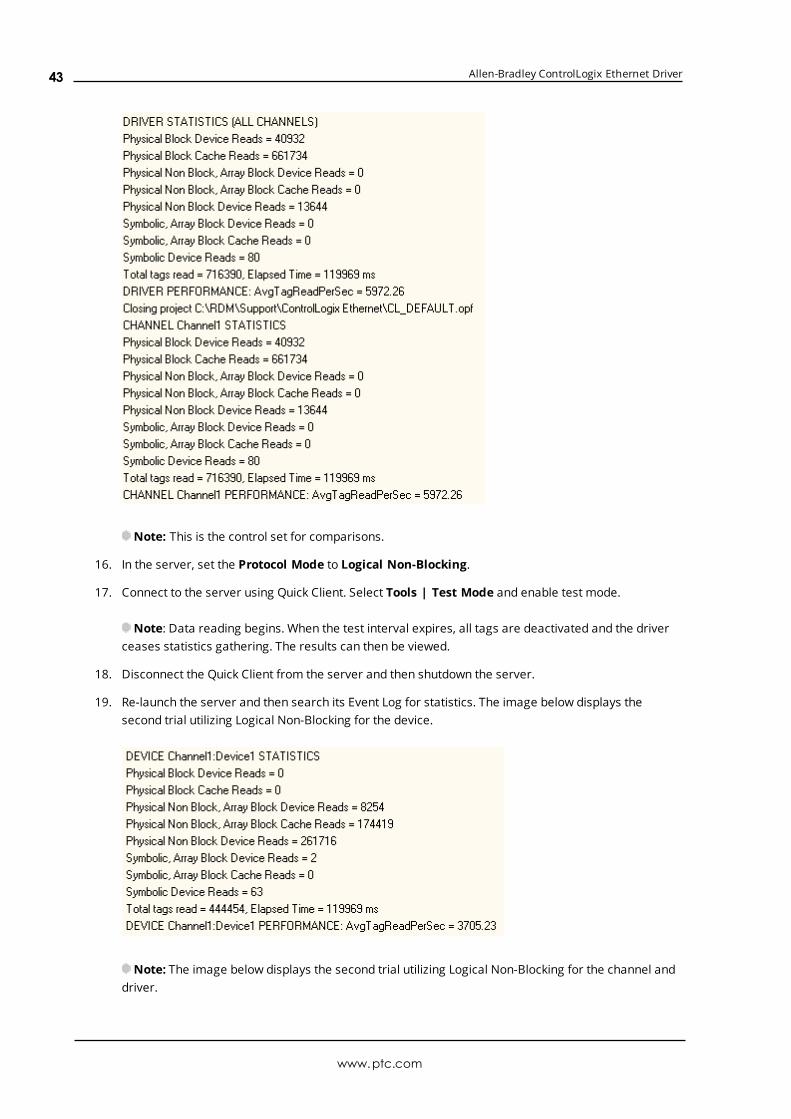
Allen-Bradley ControlLogix Ethernet Driver
Note: This is the control set for comparisons.
16. In the server, set the Protocol Mode to Logical Non-Blocking.
17. Connect to the server using Quick Client. Select Tools | Test Mode and enable test mode.
Note: Data reading begins. When the test interval expires, all tags are deactivated and the driverceases statistics gathering. The results can then be viewed.
18. Disconnect the Quick Client from the server and then shutdown the server.
19. Re-launch the server and then search its Event Log for statistics. The image below displays thesecond trial utilizing Logical Non-Blocking for the device.
Note: The image below displays the second trial utilizing Logical Non-Blocking for the channel anddriver.
www.ptc.com
43

Allen-Bradley ControlLogix Ethernet Driver
20. From the server, set the Protocol Mode to Symbolic to see how the performance fared prior toAllen-Bradley ControlLogix Ethernet Driver version 4.6.0.xx.
21. Connect to the server using the Quick Client. Then, click Tools | Test Mode and enable test mode.
Note: Data reading begins. When the test interval expires, all tags are deactivated and the driverceases statistics gathering. The results can then be viewed.
22. Disconnect the Quick Client from the server and then shutdown the server.
23. Re-launch the server and search its Event Log for statistics. The image below displays the third trialutilizing Symbolic for the device.
The image below displays the third trial utilizing Symbolic for the channel and driver.
www.ptc.com
44
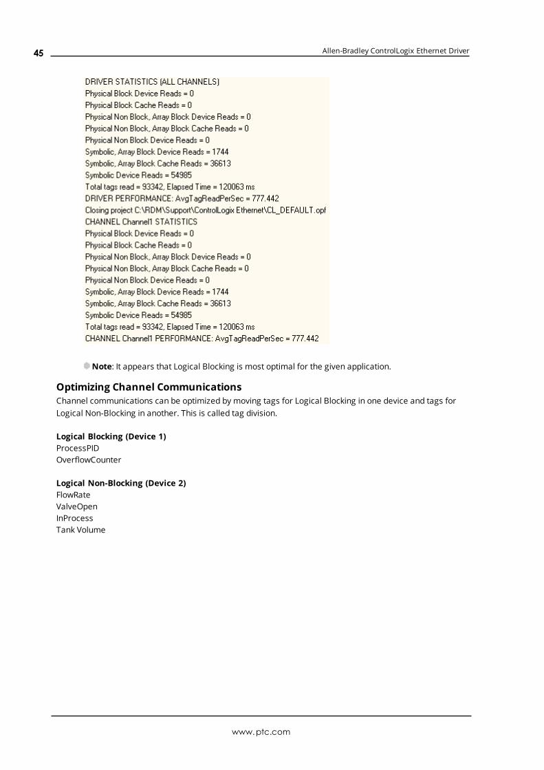
Allen-Bradley ControlLogix Ethernet Driver
Note: It appears that Logical Blocking is most optimal for the given application.
Optimizing Channel CommunicationsChannel communications can be optimized by moving tags for Logical Blocking in one device and tags forLogical Non-Blocking in another. This is called tag division.
Logical Blocking (Device 1)ProcessPIDOverflowCounter
Logical Non-Blocking (Device 2)FlowRateValveOpenInProcessTank Volume
www.ptc.com
45

Allen-Bradley ControlLogix Ethernet Driver
1. Repeat Steps 4 through 15. In Step 11, make sure that Device 1 is Logical Blocking and Device 2 isLogical Non-Blocking.
2. Launch the server and search the server Event Log for statistics. The image below displays the fourthtrial utilizing tag division for the device.
Note: The image below displays the fourth trial utilizing tag division for the channel and driver.
www.ptc.com
46

Allen-Bradley ControlLogix Ethernet Driver
Note: The individual device statistics do not look impressive because the two devices are running onseparate statistic counters. The key to this test is that the channel and driver statistics are better (6126) thanusing one channel/one device with either Logical Blocking (5972) or Logical Non-Blocking (3705).
Optimize ApplicationThe application can be optimized by moving Device 1 to one channel and Device 2 to another.
Logical Blocking (Channel1.Device 1ProcessPIDOverflowCounter
Logical Non-Blocking (Channel2.Device 2)FlowRateValveOpenInProcessTank Volume
www.ptc.com
47
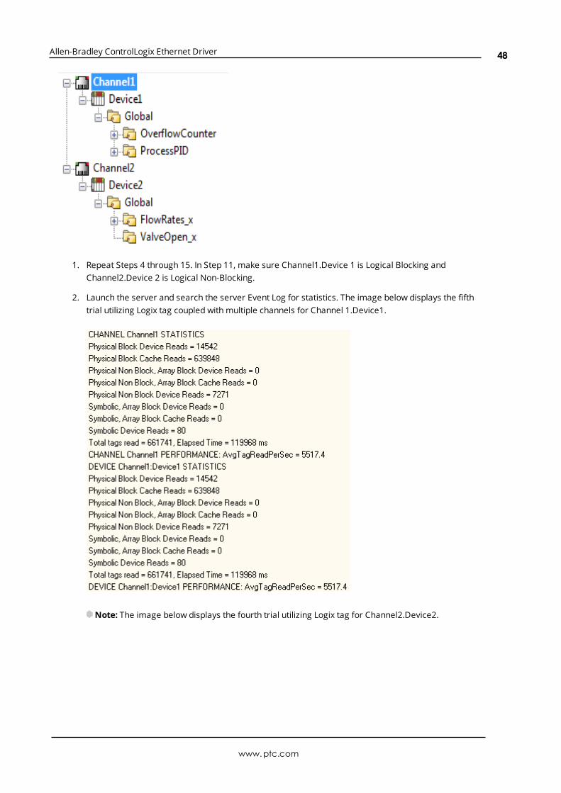
Allen-Bradley ControlLogix Ethernet Driver
1. Repeat Steps 4 through 15. In Step 11, make sure Channel1.Device 1 is Logical Blocking andChannel2.Device 2 is Logical Non-Blocking.
2. Launch the server and search the server Event Log for statistics. The image below displays the fifthtrial utilizing Logix tag coupled with multiple channels for Channel 1.Device1.
Note: The image below displays the fourth trial utilizing Logix tag for Channel2.Device2.
www.ptc.com
48

Allen-Bradley ControlLogix Ethernet Driver
Note: The image below displays the fourth trial utilizing tag division for the driver.
Results
Server Project LayoutDriver Performance(Reads/Second)
Improvement OverSymbolic
Single ChannelSingle Device with LogicalBlocking
5972 768%
Single ChannelSingle Device with Logical Non-Blocking
3705 476%
Single ChannelSingle Device with Symbolic
777 N/A
Single ChannelMultiple Devices with Tag Division
6126 788%
www.ptc.com
49

Allen-Bradley ControlLogix Ethernet Driver
Server Project LayoutDriver Performance(Reads/Second)
Improvement OverSymbolic
Multiple ChannelsMultiple Devices with Tag Division
6426 827%
ConclusionsThe project began with a single channel and a single device, which is the default behavior for a singlecontroller. All tags were imported from this controller to this channel.device. All three protocol modes werethen tested to see which would provide the best performance. In this case, Logical Blocking Protocol was thebest. The best protocol depends on the application at hand. When performance is crucial, it is worthperforming Logical Blocking and Logical Non-Blocking trials to determine which is the best protocol mode forthe application. Symbolic protocol is not necessary because it never meets the performance caliber of eitherof the other protocol modes. It is shown here for the sake of the example.
Measures were taken to optimize communications using the tips outlined in Optimizing Communications.Most notably, tag division was used to place the Logical Blocking type tags in a device assigned LogicalBlocking and the Logical Non-Blocking type tags in a device assigned Logical Non-Blocking. Furthermore,both devices resided on the same channel. The results show an improvement over using Logical Blocking ona single device. This is because some tags lend themselves better to one protocol mode over another. Forexample, reading an entire COUNTER benefits from Logical Blocking over Logical Non-Blocking since it'smuch faster reading the COUNTER as a block then as individual members.
Measures were also taken to optimize the application by placing devices on their own channel. Using thedevices created in the previous trial, a Logical Blocking device was placed on one channel and a Logical Non-Blocking device on another. The results show improvement over the single channel / multiple devicesscenario from the previous trial. This reinforces the idea that performance is improved by having as fewdevices per channel and as many channels as necessary.
After using these three optimization methods, the project has an 827% performance increase over Allen-Bradley ControlLogix Ethernet Driver version earlier than 4.6.0.xx. Tag division and multiple channelsimproved the performance by 107%. The performance increase is more apparent with larger projects.
www.ptc.com
50
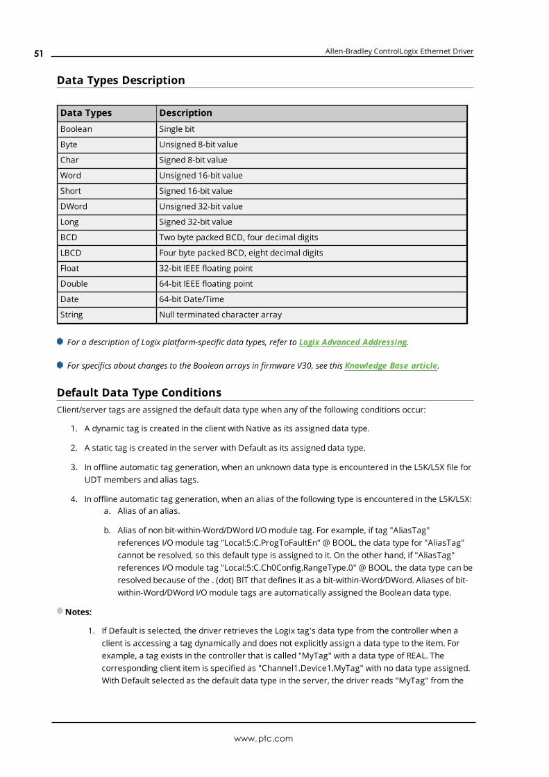
Allen-Bradley ControlLogix Ethernet Driver
Data Types Description
Data Types Description
Boolean Single bit
Byte Unsigned 8-bit value
Char Signed 8-bit value
Word Unsigned 16-bit value
Short Signed 16-bit value
DWord Unsigned 32-bit value
Long Signed 32-bit value
BCD Two byte packed BCD, four decimal digits
LBCD Four byte packed BCD, eight decimal digits
Float 32-bit IEEE floating point
Double 64-bit IEEE floating point
Date 64-bit Date/Time
String Null terminated character array
For a description of Logix platform-specific data types, refer to Logix Advanced Addressing.
For specifics about changes to the Boolean arrays in firmware V30, see this Knowledge Base article.
Default Data Type ConditionsClient/server tags are assigned the default data type when any of the following conditions occur:
1. A dynamic tag is created in the client with Native as its assigned data type.
2. A static tag is created in the server with Default as its assigned data type.
3. In offline automatic tag generation, when an unknown data type is encountered in the L5K/L5X file forUDT members and alias tags.
4. In offline automatic tag generation, when an alias of the following type is encountered in the L5K/L5X:a. Alias of an alias.
b. Alias of non bit-within-Word/DWord I/O module tag. For example, if tag "AliasTag"references I/O module tag "Local:5:C.ProgToFaultEn" @ BOOL, the data type for "AliasTag"cannot be resolved, so this default type is assigned to it. On the other hand, if "AliasTag"references I/O module tag "Local:5:C.Ch0Config.RangeType.0" @ BOOL, the data type can beresolved because of the . (dot) BIT that defines it as a bit-within-Word/DWord. Aliases of bit-within-Word/DWord I/O module tags are automatically assigned the Boolean data type.
Notes:
1. If Default is selected, the driver retrieves the Logix tag's data type from the controller when aclient is accessing a tag dynamically and does not explicitly assign a data type to the item. Forexample, a tag exists in the controller that is called "MyTag" with a data type of REAL. Thecorresponding client item is specified as "Channel1.Device1.MyTag" with no data type assigned.With Default selected as the default data type in the server, the driver reads "MyTag" from the
www.ptc.com
51

Allen-Bradley ControlLogix Ethernet Driver
controller and determine that it is a REAL in the response, providing the client a data type ofFloat.
2. Since the majority of I/O module tags are not bit-within-Word/DWord tags, it is advised that thedefault type be set to the majority data type as observed in the .ACD project. For example, if 75%of alias I/O module tags are INT tags, set the default type to INT.
www.ptc.com
52

Allen-Bradley ControlLogix Ethernet Driver
Address DescriptionsAddress specifications vary depending on the model in use. For the model of interest's address information,refer to the table below.
Model
MicroLogix X X X X X X X X X X X X X X
PLC5 X X X X X X X X X X X X X X X
SLC5/05 X X X X X X X X X X X
See also: Logix AddressingMIcroLogix AddressingPLC-5 Series AddressingSLC 500 Modular I/O Addressing
ProtocolClass
Models Help Link
Logix-EthernetControlLogix 5500 Ethernet, CompactLogix 5300 Ethernet,FlexLogix 5400 Ethernet, SoftLogix 5800
Logix Addressing
DH+ Gateway DH+ Gateway: PLC-5 DH+ Gateway: SLC 5/04
PLC-5 SeriesAddressingSLC 500 ModularI/O Addressing
ControlNetGateway
ControlNet Gateway: PLC-5CPLC-5 SeriesAddressing
1761-NET-ENI
ENI: ControlLogix 5500ENI: CompactLogix 5300ENI: FlexLogix 5400ENI: MicroLogixENI: SLC 500 Fixed I/OENI: SLC 500 Modular I/OENI: PLC-5
Logix AddressingMicroLogixAddressingSLC 500 Fixed I/OAddressingSLC 500 ModularI/O AddressingPLC-5 SeriesAddressing
MicroLogix1100 Ethernet
MicroLogix 1100MicroLogixAddressing
MicroLogix1400 Ethernet
MicroLogix 1400MicroLogixAddressing
For more information on the controller's pre-defined data types, refer to the device's documentation.
www.ptc.com
53

Allen-Bradley ControlLogix Ethernet Driver
Logix AddressingFor more information on these models' tag-based addressing and relationship to the Allen-Bradley
ControlLogix Ethernet Driver, refer to Logix Tag-Based Addressing.
ControlLogix 5500 Addressing for EthernetControlLogix is a member of the Logix family and part of Rockwell Automation's Integrated Architecture. Thismeans it uses a tag or symbol-based addressing structure. Logix tags differ from conventional PLC dataitems in that the tag name itself is the address, not a physical or logical address.
ControlLogix 5500 Addressing for ENIControlLogix is a member of the Logix family and part of Rockwell Automation's Integrated Architecture. Thismeans it uses a tag or symbol-based addressing structure. Logix tags differ from conventional PLC dataitems in that the tag name itself is the address, not a physical or logical address.
ControlLogix 5500 Addressing for Serial GatewayControlLogix is a member of the Logix family and part of Rockwell Automation's Integrated Architecture. Thismeans it uses a tag or symbol-based addressing structure. Logix tags differ from conventional PLC dataitems in that the tag name itself is the address, not a physical or logical address.
CompactLogix 5300 Addressing for EthernetCompactLogix is a member of the Logix family and part of Rockwell Automation's Integrated Architecture.This means it uses a tag or symbol-based addressing structure. Logix tags differ from conventional PLC dataitems in that the tag name itself is the address, not a physical or logical address.
CompactLogix 5300 Addressing for ENICompactLogix is a member of the Logix family and part of Rockwell Automation's Integrated Architecture.This means it uses a tag or symbol-based addressing structure. Logix tags differ from conventional PLC dataitems in that the tag name itself is the address, not a physical or logical address.
CompactLogix 5300 Addressing for Serial GatewayCompactLogix is a member of the Logix family and part of Rockwell Automation's Integrated Architecture.This means it uses a tag or symbol-based addressing structure. Logix tags differ from conventional PLC dataitems in that the tag name itself is the address, not a physical or logical address.
FlexLogix 5400 Addressing for EthernetFlexLogix is a member of the Logix family and part of Rockwell Automation's Integrated Architecture. Thismeans it uses a tag or symbol-based addressing structure. Logix tags differ from conventional PLC dataitems in that the tag name itself is the address, not a physical or logical address.
FlexLogix 5400 Addressing for ENIFlexLogix is a member of the Logix family and part of Rockwell Automation's Integrated Architecture. Thismeans it uses a tag or symbol-based addressing structure. Logix tags differ from conventional PLC dataitems in that the tag name itself is the address, not a physical or logical address.
FlexLogix 5400 Addressing for Serial GatewayFlexLogix is a member of the Logix family and part of Rockwell Automation's Integrated Architecture. Thismeans it uses a tag or symbol-based addressing structure. Logix tags differ from conventional PLC dataitems in that the tag name itself is the address, not a physical or logical address.
www.ptc.com
54
Allen-Bradley ControlLogix Ethernet Driver
SoftLogix 5800 AddressingSoftlLogix is a member of the Logix family and part of Rockwell Automation's Integrated Architecture. Thismeans it uses a tag or symbol-based addressing structure. Logix tags differ from conventional PLC dataitems in that the tag name itself is the address, not a physical or logical address.
SoftLogix 5800 Addressing for Serial GatewaySoftlLogix is a member of the Logix family and part of Rockwell Automation's Integrated Architecture. Thismeans it uses a tag or symbol-based addressing structure. Logix tags differ from conventional PLC dataitems in that the tag name itself is the address, not a physical or logical address.
MicroLogix AddressingMicroLogix Addressing for EtherNet/IP GatewayThe actual number of addresses available depends on the model of the PLC. The ranges have been openedup to allow for maximum flexibility with future models. If the driver finds at Runtime that an address is notpresent in the device, it posts an error message and then removes the tag from its scan list. For moreinformation on file-specific addressing, select a link from the list below.
Output FilesInput FilesStatus FilesBinary FilesTimer FilesCounter FilesControl FilesInteger FilesFloat FilesASCII FilesString FilesLong FilesMicroLogix PID FilesMicroLogix Message Files
For information on function files, select a link from the list below.
High-Speed Counter File (HSC)Real-Time Clock File (RTC)Channel 0 Communication Status File (CS0)Channel 1 Communication Status File (CS1)I/O Module Status File (IOS)
MicroLogix Addressing for ENIThe actual number of addresses available depends on the model of the PLC. The ranges have been openedup to allow for maximum flexibility with future models. If the driver finds at Runtime that an address is notpresent in the device, it posts an error message and then removes the tag from its scan list. For moreinformation on file-specific addressing, select a link from the list below.
www.ptc.com
55

Allen-Bradley ControlLogix Ethernet Driver
Output FilesInput FilesStatus FilesBinary FilesTimer FilesCounter FilesControl FilesInteger FilesFloat FilesASCII FilesString FilesLong FilesMicroLogix PID FilesMicroLogix Message Files
For information on function files, select a link from the list below.
High-Speed Counter File (HSC)Real-Time Clock File (RTC)Channel 0 Communication Status File (CS0)Channel 1 Communication Status File (CS1)I/O Module Status File (IOS)
MicroLogix 1100 AddressingThe actual number of addresses available depends on the model of the PLC. The ranges have been openedup to allow for maximum flexibility with future models. If the driver finds at Runtime that an address is notpresent in the device, it posts an error message and then removes the tag from its scan list. For moreinformation on file-specific addressing, select a link from the list below.
Output FilesInput FilesStatus FilesBinary FilesTimer FilesCounter FilesControl FilesInteger FilesFloat FilesString FilesLong FilesMicroLogix PID FilesMicroLogix Message Files
For information on function files, select a link from the list below.
www.ptc.com
56

Allen-Bradley ControlLogix Ethernet Driver
High-Speed Counter File (HSC)Real-Time Clock File (RTC)Channel 0 Communication Status File (CS0)Channel 1 Communication Status File (CS1)I/O Module Status File (IOS)
MicroLogix 1400 AddressingThe actual number of addresses available depends on the model of the PLC. The ranges have been openedup to allow for maximum flexibility with future models. If the driver finds at Runtime that an address is notpresent in the device, it posts an error message and then removes the tag from its scan list. For moreinformation on file-specific addressing, select a link from the list below.
Output FilesInput FilesStatus FilesBinary FilesTimer FilesCounter FilesControl FilesInteger FilesFloat FilesASCII FilesString FilesLong FilesMicroLogix PID FilesMicroLogix Message Files
For information on function files, select a link from the list below.
High-Speed Counter File (HSC)Real-Time Clock File (RTC)Channel 0 Communication Status File (CS0)Channel 1 Communication Status File (CS1)I/O Module Status File (IOS)
SLC 500 Fixed I/O AddressingSLC 500 Fixed I/O Addressing for EtherNet/IP GatewayFor more information on file-specific addressing, select a link from the list below.
Output FilesInput FilesStatus FilesBinary FilesTimer FilesCounter Files
www.ptc.com
57
Allen-Bradley ControlLogix Ethernet Driver
Control FilesInteger Files
SLC 500 Fixed I/O Addressing for ENIFor more information on file-specific addressing, select a link from the list below.
Output FilesInput FilesStatus FilesBinary FilesTimer FilesCounter FilesControl FilesInteger Files
SLC 500 Modular I/O AddressingSLC 500 Modular I/O Addressing for DH+The actual number of addresses available depends on the model of the PLC. The ranges have been openedup to allow for maximum flexibility with future models. If the driver finds at Runtime that an address is notpresent in the device, it posts an error message and then removes the tag from its scan list. For moreinformation on file-specific addressing, select a link from the list below.
Output FilesInput FilesStatus FilesBinary FilesTimer FilesCounter FilesControl FilesInteger FilesFloat FilesASCII FilesString Files
SLC 500 Modular I/O Addressing for EtherNet/IP GatewayThe actual number of addresses available depends on the model of the PLC. The ranges have been openedup to allow for maximum flexibility with future models. If the driver finds at Runtime that an address is notpresent in the device, it posts an error message and then removes the tag from its scan list. For moreinformation on file-specific addressing, select a link from the list below.
Output FilesInput FilesStatus FilesBinary FilesTimer FilesCounter Files
www.ptc.com
58
Allen-Bradley ControlLogix Ethernet Driver
Control FilesInteger FilesFloat FilesASCII FilesString Files
SLC 500 Modular I/O Addressing for ENIThe actual number of addresses available depends on the model of the PLC. The ranges have been openedup to allow for maximum flexibility with future models. If the driver finds at Runtime that an address is notpresent in the device, it posts an error message and then removes the tag from its scan list. For moreinformation on file-specific addressing, select a link from the list below.
Output FilesInput FilesStatus FilesBinary FilesTimer FilesCounter FilesControl FilesInteger FilesFloat FilesASCII FilesString Files
PLC-5 Series AddressingPLC-5 Series Addressing for ControlNetFor more information on file-specific addressing, select a link from the list below.
Output FilesInput FilesStatus FilesBinary FilesTimer FilesCounter FilesControl FilesInteger FilesFloat FilesASCII FilesString FilesBCD FilesPID FilesMessage FilesBlock Transfer Files
PLC-5 Series Addressing for DH+
www.ptc.com
59
Allen-Bradley ControlLogix Ethernet Driver
For more information on file-specific addressing, select a link from the list below.
Output FilesInput FilesStatus FilesBinary FilesTimer FilesCounter FilesControl FilesInteger FilesFloat FilesASCII FilesString FilesBCD FilesPID FilesMessage FilesBlock Transfer Files
PLC-5 Series Addressing for EtherNet/IP GatewayFor more information on file-specific addressing, select a link from the list below.
Output FilesInput FilesStatus FilesBinary FilesTimer FilesCounter FilesControl FilesInteger FilesFloat FilesASCII FilesString FilesBCD FilesPID FilesMessage FilesBlock Transfer Files
PLC-5 Series Addressing for ENIFor more information on file-specific addressing, select a link from the list below.
Output FilesInput FilesStatus FilesBinary FilesTimer Files
www.ptc.com
60

Allen-Bradley ControlLogix Ethernet Driver
Counter FilesControl FilesInteger FilesFloat FilesASCII FilesString FilesBCD FilesPID FilesMessage FilesBlock Transfer Files
Logix Tag-Based AddressingRockwell Automation's Integrated Architecture uses a tag or symbol-based addressing structure that iscommonly referred to as Logix tags (or Native tags). These tags differ from conventional PLC data items inthat the tag name itself is the address, not a physical or logical address.
Note: Throughout this help file, Logix tags are assumed to be global in nature unless specified otherwise.
The Allen-Bradley ControlLogix Ethernet Driver allows users to access the controller's atomic data types:BOOL, SINT, INT, DINT, LINT, and REAL. Although some of the pre-defined types are structures, they areultimately based on these atomic data types. Thus, all non-structure (atomic) members of a structure areaccessible. For example, a TIMER cannot be assigned to a server tag but an atomic member of the TIMERcan be assigned to the tag (such as TIMER.EN, TIMER.ACC, and so forth). If a structure member is a structureitself, both structures would have to be expanded to access an atomic member of the substructure. This ismore common with user and module-defined types and is not found in any of the pre-defined types.
Atomic DataType
Description Range
BOOL Single-bit valueVT_BOOL
0, 1
SINT Signed 8-bit value VT_UI1 -128 to 127
INT Signed 16-bit value VT_I2 -32,768 to 32,767
DINT Signed 32-bit value VT_I4 -2,147,483,648 to 2,147,483,647
LINT Signed 64-bit value VT_I8–9,223,372,036,854,775,808 to9,223,372,036,854,775,807
REAL32-bit IEEE floatingpoint
VT_R4 1.1755 E-38 to 3.403E38, 0, -3.403E-38 to -1.1755
See Also: Logix Advanced Addressing
Client/Server Tag Address RulesLogix tag names correspond to client/server tag addresses. Logix tag names (entered via RSLogix5000)follow the IEC 1131-3 identifier rules. Client/server tag addresses follow these same rules. They are asfollows:
l Must begin with an alphabetic (A-Z, a-z) character or an underscore (_).
l Can only contain alphanumeric characters and underscores.
www.ptc.com
61

Allen-Bradley ControlLogix Ethernet Driver
l Can have as many as 40 characters.
l Cannot have consecutive underscores.
l Are not case sensitive.
Client/Server Tag Name RulesTag name assignment in the server differs from address assignment in that names cannot begin with anunderscore.
Note: Logix tag names should be kept to a minimum in size for optimum performance. The smaller thename, the more requests that are able fit in a single transaction.
Symbolic Mode users should keep the client/server tag addresses below 400 characters. For example,tagarray[1,2,4].somestruct.substruct_array[3].basetag.[4] is 57 characters in length. Since a packet can onlyhold 500 data bytes, any overhead bytes that need to be added to the packet can greatly diminish the roomavailable to the characters themselves. By keeping the address below 400, the tag request remainscomplete and valid.
See Also:Performance Optimizations
Address FormatsThere are several ways to address a Logix tag statically in the server or dynamically from a client. Theformat used depends on the type and usage of the tag. For example, the bit format would be used whenaccessing a bit within a SINT-type tag. For information on address format and syntax, refer to the tablebelow.
Note: All formats except for Array and String are native to RSLogix5000. Therefore, when referencing anatomic data type, an RSLogix 5000 tag name can be copied and pasted into the server's tag address fieldand be valid.
Format Syntax Example Notes
Standard <logix tag name> tag_1 Tag cannot be an array.
ArrayElement
<logix array tagname> [dim 1,dim2, dim 3]
tag_1 [2, 58,547]tag_1 [0, 3]
Dimension range = 1 to 3 | element range = 0 to 65535
Arrayw/oOffset*
<logix array tagname> {#columns}<logix array tagname> {# rows}{#columns}
tag_1 {8}tag_1 {2}{4}
Dimension range = 1 to 2 | element range = 1 to 65535
The number of elements to read/write equals # of rowstimes # of columns. If no rows are specified, # of rowsdefault to 1.
The array begins at a zero offset (array index equals 0for all dimensions).
Array w/Offset*
<logix arrayelement tag>[offset1,offset2]{#columns}<logix arrayelement tag>[offset1,offset2]{#
tag_1 [2, 3]{10}tag_1 [2, 3] 2}{5}
The array begins at an offset specified by the dimensionsin the array element tag. The array always covers thehighest dimension. Tag_1[2,3]{10} would produce anarray of elements tag_1[2,3] -> tag_1[2,13]
www.ptc.com
62

Allen-Bradley ControlLogix Ethernet Driver
Format Syntax Example Notes
rows}{# columns}
Bit
<logix tagname>.bit<logix tag name>.[bit]
tag_1.0tag_1.[0]
Bit range = 0 to 31
If tag is an array, it must be a BOOL array, otherwise tagcannot be an array.
String<logix tagname>/<maximumstring length>
tag_1.Data/4Stringtag_1.DataSINTarraytag_1/16
Length range = 1 to 65535
The maximum number of characters that can read/writeto the string.
*Since this format may request more than one element, the order in which array data is passed depends onthe dimension of the Logix Array tag. For example, if rows times cols = 4 and the Controller tag is a 3X3element array, then the elements that are being referenced are array_tag [0,0], array_tag [0,1], array_tag[0,2], and array_tag [1,0] in that exact order. The results would be different if the Controller tag were a 2X10element array.
For more information on how elements are referenced for 1, 2, and 3 dimensional arrays, refer to Ordering ofArray Data.
Tag ScopeGlobal TagsGlobal tags are Logix tags that have global scope in the controller. Any program or task can access Globaltags; however, the number of ways a Global tag can be referenced depends on its Logix data type and theaddress format being used.
Program TagsProgram tags are identical to Global tags except that a Program tag's scope is local to the program in whichit is defined. Program tags follow the same addressing rules and limitations as Global tags, but are prefixedwith the following notation:
Program: <program name>.
For example, Logix tag "tag_1" in program "prog_1" would be addressed as "Program:prog_1.tag_1" in aclient/server tag address.
Structure Tag AddressingLogix Structure tags (Global or Program) are tags with one or more member tags. Member tags can beatomic or structured in nature.
<structure name>. <atomic-type tag>
This implies that a substructure would be addressed as:
<structure name> . <substructure name> .<atomic-type tag>
www.ptc.com
63
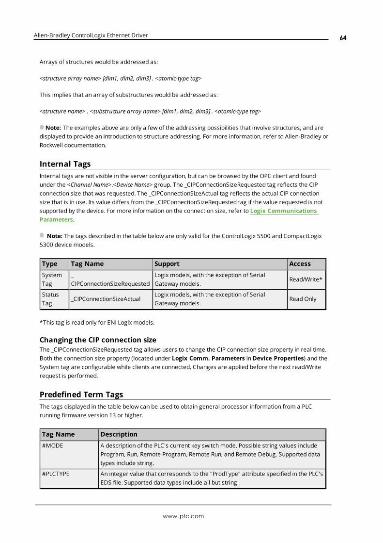
Allen-Bradley ControlLogix Ethernet Driver
Arrays of structures would be addressed as:
<structure array name> [dim1, dim2, dim3] . <atomic-type tag>
This implies that an array of substructures would be addressed as:
<structure name> . <substructure array name> [dim1, dim2, dim3] . <atomic-type tag>
Note: The examples above are only a few of the addressing possibilities that involve structures, and aredisplayed to provide an introduction to structure addressing. For more information, refer to Allen-Bradley orRockwell documentation.
Internal TagsInternal tags are not visible in the server configuration, but can be browsed by the OPC client and foundunder the <Channel Name>.<Device Name> group. The _CIPConnectionSizeRequested tag reflects the CIPconnection size that was requested. The _CIPConnectionSizeActual tag reflects the actual CIP connectionsize that is in use. Its value differs from the _CIPConnectionSizeRequested tag if the value requested is notsupported by the device. For more information on the connection size, refer to Logix CommunicationsParameters.
Note: The tags described in the table below are only valid for the ControlLogix 5500 and CompactLogix5300 device models.
Type Tag Name Support Access
SystemTag
_CIPConnectionSizeRequested
Logix models, with the exception of SerialGateway models.
Read/Write*
StatusTag
_CIPConnectionSizeActualLogix models, with the exception of SerialGateway models.
Read Only
*This tag is read only for ENI Logix models.
Changing the CIP connection sizeThe _CIPConnectionSizeRequested tag allows users to change the CIP connection size property in real time.Both the connection size property (located under Logix Comm. Parameters in Device Properties) and theSystem tag are configurable while clients are connected. Changes are applied before the next read/Writerequest is performed.
Predefined Term TagsThe tags displayed in the table below can be used to obtain general processor information from a PLCrunning firmware version 13 or higher.
Tag Name Description
#MODE A description of the PLC's current key switch mode. Possible string values includeProgram, Run, Remote Program, Remote Run, and Remote Debug. Supported datatypes include string.
#PLCTYPE An integer value that corresponds to the "ProdType" attribute specified in the PLC'sEDS file. Supported data types include all but string.
www.ptc.com
64

Allen-Bradley ControlLogix Ethernet Driver
Tag Name Description
#REVISION Firmware revision displayed as "<major>.<minor>". Supported data types includestring.
#PROCESSORNAME The processor name that corresponds to the "ProdName" attribute specified in thePLC's EDS file. Supported data types include string.
#STATUS Indicates the PLC's status. Possible values include OK (1) and Faulted (0).Supported data types include all but date.
#PRODUCTCODE An integer value that corresponds to the "ProdCode" attribute specified in thePLC's EDS file. Supported data types include all but string.
#VENDORID An integer value that corresponds to the "VendCode" attribute specified in thePLC's EDS file. Supported data types include all but string.
Addressing Atomic Data TypesBelow are suggested usages and addressing possibilities for a Logix data type given the address formatsavailable. Examples are also given for reinforcement. Click on Advanced for advanced addressingpossibilities for the given atomic data type.Note: Empty cells do not necessarily indicate a lack of support.
Atomic DataType
Standard ArrayElement
Array with or withoutOffset
Bit String
BOOL
Client/ServerData Type
Advanced
Boolean
Boolean
(BOOL 1dimensionalarray)
Boolean Array
(BOOL 1 dimensional array)
Client/ServerTag Example
BOOLTAG BOOLARR[0] BOOLARR[0]{32}
SINT
Client/ServerData Type
Advanced
Byte, Char Byte, Char
Byte Array, Char Array
(SINT 1/2/3 dimensionalarray)
Boolean
(Bit w/iSINT)
String
(SINT 1/2/3dimensionalarray)
Client/ServerTag Example
SINTTAG SINTARR[0] SINTARR[0]{4} SINTTAG.0 SINTARR/4
INT
Client/ServerData Type
Advanced
Word,Short
Word, ShortWord Array, Short Array (INT1/2/3 dimensional array)
Boolean
(Bit w/iINT)
See AdvancedAddressing INT.
Client/ServerTag Example
INTTAG INTARR[0] INTARR[0]{4} INTTAG.0
DINT
Client/Server DWord, DWord, Long DWord Array, Long Array Boolean See Advanced
www.ptc.com
65

Allen-Bradley ControlLogix Ethernet Driver
Atomic DataType
Standard ArrayElement
Array with or withoutOffset
Bit String
Data Type
AdvancedLong (Bit w/i
DINT)
AddressingDINT.
Client/ServerTag Example
DINTTAG DINTARR[0] DINTARR[0]{4} DINTTAG.0
LINT
Client/ServerData Type
Advanced
Double,Date
Double, Date Double Array
Client/ServerTag Example
LINTTAG LINTARR[0] LINTARR[0]{4}
REAL
Client/ServerData Type
Advanced
Float Float Float ArraySee AdvancedAddressingREAL.
Client/ServerTag Example
REALTAG REALARR[0] REALARR[0]{4}
Addressing Structure Data TypesOnly the atomic structure members can be addressed at the structure level. For more information, refer tothe examples below.
Logix TagMyTimer @ TIMER
Client/Server Tag1. Invalid
TimerTag address = MyTimerTimerTag data type = ??
2. ValidTimerTag address = MyTimer.ACCTimerTag data type = DWord
Addressing STRING Data TypeSTRING is a pre-defined Logix data type whose structure contains two members: DATA and LEN. DATA is anarray of SINTs and stores the characters of the STRING. LEN is a DINT and represents the number ofcharacters in DATA to display to a client.
Because LEN and DATA are atomic members, they must be referenced independently from a client/server.The syntax is as shown below.
www.ptc.com
66

Allen-Bradley ControlLogix Ethernet Driver
Description Syntax Example
STRING Value DATA/<Maximum STRING length > MYSTRING.DATA/82
Actual STRING length LEN MYSTRING.LEN
ReadsThe STRING read from DATA is terminated by the following:
a. The first null terminator encountered.
b. The value in LEN if a) doesn't occur first.
c. The <Maximum STRING length > if either a) or b) doesn't occur first.
ExampleMYSTRING.DATA contains "Hello World" in the PLC, but LEN is manually set to 5. A read ofMYSTRING.DATA/82 displays "Hello". If LEN is set to 20, MYSTRING.DATA/82 displays "Hello World".
WritesWhen a STRING value is written to DATA, the driver also writes to LEN with the length of DATA written. If thewrite to LEN fails for any reason, the write operation to DATA is considered failed as well (despite the factthat the DATA write to the controller succeeded).
Note: This behavior was designed specifically for Logix tags of type STRING or a custom derivative of it.The following precautions apply to users who wish to implement their own STRING in UDTs.
l If a UDT exists that has a DATA member referenced as a STRING and a LEN member referenced as aDINT, the write to LEN succeeds regardless of the intentions of LEN for the given UDT. Care must betaken when designing UDTs to avoid this possibility if LEN is not intended to be the length of DATA.
l If a UDT exists that has a DATA member referenced as a STRING but does not have a LEN member,the write to LEN fails silently without consequence to DATA.
ExampleMYSTRING.DATA/82 holds the value "Hello World." MYSTRING.LEN holds 11. If the value "Alarm Triggered"is written to MYSTRING.DATA/82, 15 is written to MYSTRING.LEN. If the write to MYSTRING.LEN fails,MYSTRING.LEN holds its previous value of 11 while MYSTRING.DATA/82 displays the first 11 characters("Alarm Trigg"). If the write to MYSTRING.DATA/82 fails, neither tag is affected.
Terminate String Data at LENIn the logical addressing modes, reading STRING.DATA causes an automatic read of STRING.LEN in SymbolicMode. This may be bypassed by disabling the Terminate String Data at LEN option. For more information,refer to Logix Options.
Ordering of Logix Array DataOne-Dimensional Arrays - array [dim1]One-dimensional array data is passed to and from the controller in ascending order.for (dim1 = 0; dim1 < dim1_max; dim1++)
Example: 3 element arrayarray [0]array [1]array [2]
www.ptc.com
67
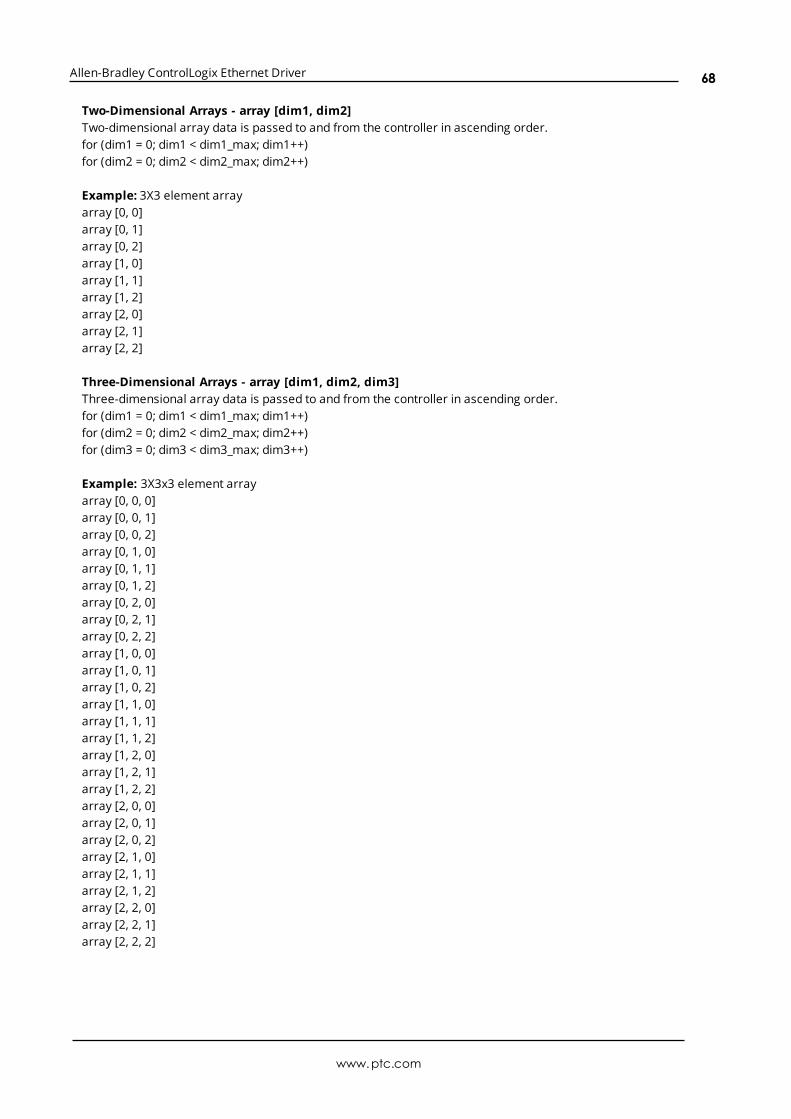
Allen-Bradley ControlLogix Ethernet Driver
Two-Dimensional Arrays - array [dim1, dim2]Two-dimensional array data is passed to and from the controller in ascending order.for (dim1 = 0; dim1 < dim1_max; dim1++)for (dim2 = 0; dim2 < dim2_max; dim2++)
Example: 3X3 element arrayarray [0, 0]array [0, 1]array [0, 2]array [1, 0]array [1, 1]array [1, 2]array [2, 0]array [2, 1]array [2, 2]
Three-Dimensional Arrays - array [dim1, dim2, dim3]Three-dimensional array data is passed to and from the controller in ascending order.for (dim1 = 0; dim1 < dim1_max; dim1++)for (dim2 = 0; dim2 < dim2_max; dim2++)for (dim3 = 0; dim3 < dim3_max; dim3++)
Example: 3X3x3 element arrayarray [0, 0, 0]array [0, 0, 1]array [0, 0, 2]array [0, 1, 0]array [0, 1, 1]array [0, 1, 2]array [0, 2, 0]array [0, 2, 1]array [0, 2, 2]array [1, 0, 0]array [1, 0, 1]array [1, 0, 2]array [1, 1, 0]array [1, 1, 1]array [1, 1, 2]array [1, 2, 0]array [1, 2, 1]array [1, 2, 2]array [2, 0, 0]array [2, 0, 1]array [2, 0, 2]array [2, 1, 0]array [2, 1, 1]array [2, 1, 2]array [2, 2, 0]array [2, 2, 1]array [2, 2, 2]
www.ptc.com
68
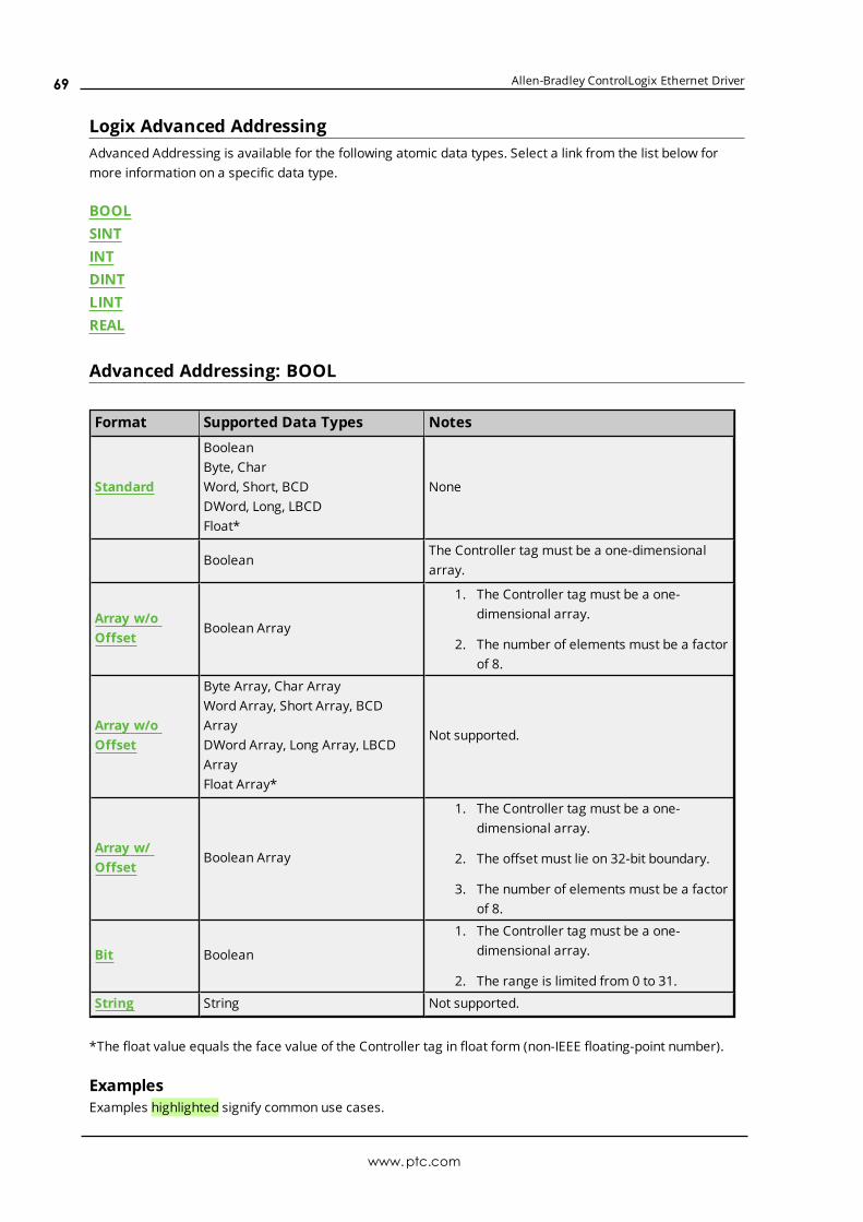
Allen-Bradley ControlLogix Ethernet Driver
Logix Advanced AddressingAdvanced Addressing is available for the following atomic data types. Select a link from the list below formore information on a specific data type.
BOOLSINTINTDINTLINTREAL
Advanced Addressing: BOOL
Format Supported Data Types Notes
Standard
BooleanByte, CharWord, Short, BCDDWord, Long, LBCDFloat*
None
BooleanThe Controller tag must be a one-dimensionalarray.
Array w/oOffset
Boolean Array
1. The Controller tag must be a one-dimensional array.
2. The number of elements must be a factorof 8.
Array w/oOffset
Byte Array, Char ArrayWord Array, Short Array, BCDArrayDWord Array, Long Array, LBCDArrayFloat Array*
Not supported.
Array w/Offset
Boolean Array
1. The Controller tag must be a one-dimensional array.
2. The offset must lie on 32-bit boundary.
3. The number of elements must be a factorof 8.
Bit Boolean
1. The Controller tag must be a one-dimensional array.
2. The range is limited from 0 to 31.
String String Not supported.
*The float value equals the face value of the Controller tag in float form (non-IEEE floating-point number).
ExamplesExamples highlighted signify common use cases.
www.ptc.com
69

Allen-Bradley ControlLogix Ethernet Driver
BOOL Controller Tag - booltag = true
Server Tag Address Format Data Type Notes
booltag Standard Boolean Value = true
booltag Standard Byte Value = 1
booltag Standard Word Value = 1
booltag Standard DWord Value = 1
booltag Standard Float Value = 1.0
booltag [3] Array Element Boolean Invalid: Tag not an array.
booltag [3] Array Element Word Invalid: Tag not an array.
booltag {1} Array w/o Offset Word Invalid: Not supported.
booltag {1} Array w/o Offset Boolean Invalid: Not supported.
booltag [3] {32} Array w/ Offset Boolean Invalid: Tag not an array.
booltag . 3 Bit Boolean Invalid: Tag not an array.
booltag / 1 String String Invalid: Not supported.
booltag / 4 String String Invalid: Not supported.
BOOL Array Controller Tag - bitarraytag = [0,1,0,1]
Server Tag Address Format Data Type Notes
bitarraytag Standard Boolean Invalid: Tag cannot be an array.
bitarraytag Standard Byte Invalid: Tag cannot be an array.
bitarraytag Standard Word Invalid: Tag cannot be an array.
bitarraytag Standard DWord Invalid: Tag cannot be an array.
bitarraytag Standard Float Invalid: Tag cannot be an array.
bitarraytag [3] Array Element Boolean Value = true
bitarraytag [3] Array Element Word Invalid: Bad data type.
bitarraytag {3} Array w/o Offset Word Invalid: Tag cannot be an array.
bitarraytag {1} Array w/o Offset Word Invalid: Tag cannot be an array.
bitarraytag {1} Array w/o Offset Boolean Invalid: Array size must be a factor of 8.
bitarraytag {32} Array w/o Offset Boolean Value = [0,1,0,1,...]
bitarraytag [3] {32} Array w/ Offset Boolean Offset must begin on 32-bit boundary.
bitarraytag[0]{32} Array w/ Offset Boolean Value = [0,1,0,1,...]
bitarraytag[32]{64} Array w/ Offset Boolean Value = [...] values not provided above
bitarraytag . 3 Bit Boolean Value = true
bitarraytag / 1 String String Invalid: Not supported.
bitarraytag / 4 String String Invalid: Not supported.
Advanced Addressing: SINT
Format Supported Data Types Notes
Standard Boolean*, Byte, Char, Word, Short, None
www.ptc.com
70
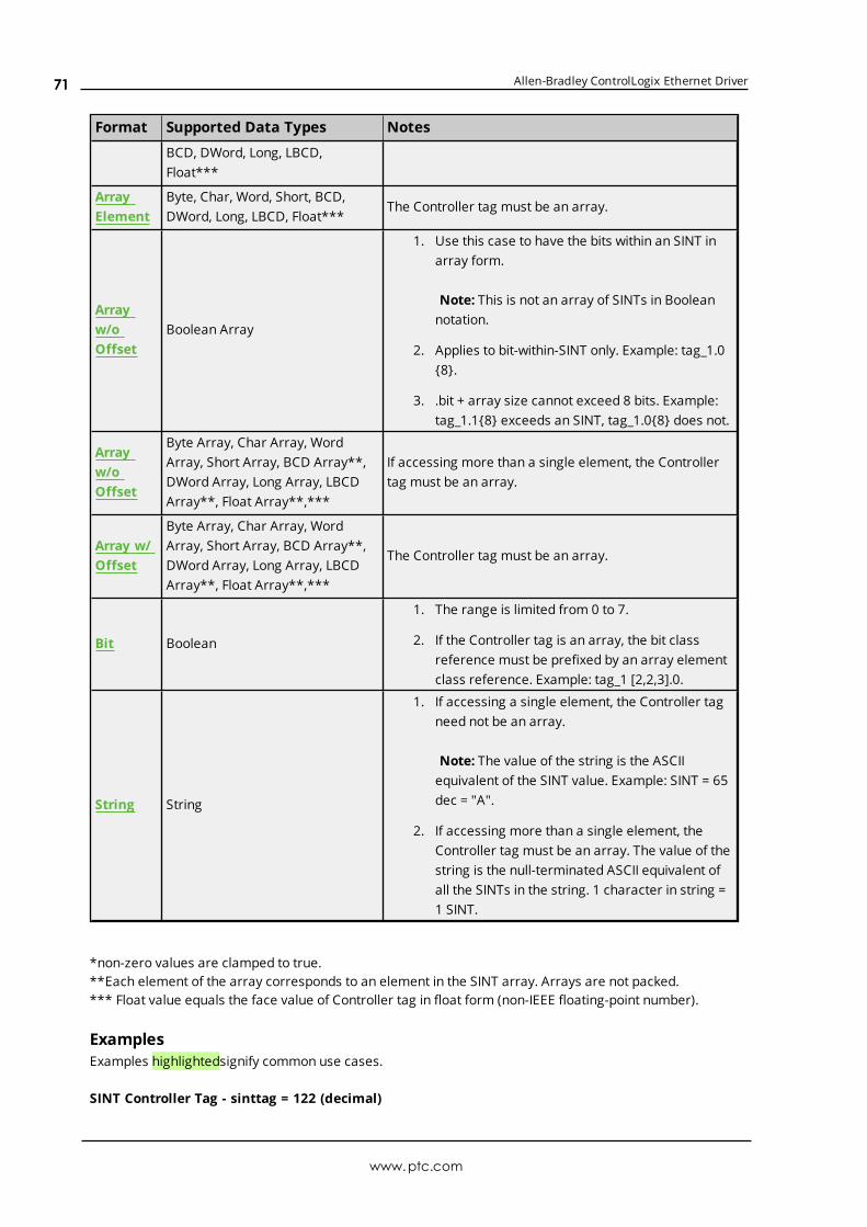
Allen-Bradley ControlLogix Ethernet Driver
Format Supported Data Types Notes
BCD, DWord, Long, LBCD,Float***
ArrayElement
Byte, Char, Word, Short, BCD,DWord, Long, LBCD, Float***
The Controller tag must be an array.
Arrayw/oOffset
Boolean Array
1. Use this case to have the bits within an SINT inarray form.
Note: This is not an array of SINTs in Booleannotation.
2. Applies to bit-within-SINT only. Example: tag_1.0{8}.
3. .bit + array size cannot exceed 8 bits. Example:tag_1.1{8} exceeds an SINT, tag_1.0{8} does not.
Arrayw/oOffset
Byte Array, Char Array, WordArray, Short Array, BCD Array**,DWord Array, Long Array, LBCDArray**, Float Array**,***
If accessing more than a single element, the Controllertag must be an array.
Array w/Offset
Byte Array, Char Array, WordArray, Short Array, BCD Array**,DWord Array, Long Array, LBCDArray**, Float Array**,***
The Controller tag must be an array.
Bit Boolean
1. The range is limited from 0 to 7.
2. If the Controller tag is an array, the bit classreference must be prefixed by an array elementclass reference. Example: tag_1 [2,2,3].0.
String String
1. If accessing a single element, the Controller tagneed not be an array.
Note: The value of the string is the ASCIIequivalent of the SINT value. Example: SINT = 65dec = "A".
2. If accessing more than a single element, theController tag must be an array. The value of thestring is the null-terminated ASCII equivalent ofall the SINTs in the string. 1 character in string =1 SINT.
*non-zero values are clamped to true.**Each element of the array corresponds to an element in the SINT array. Arrays are not packed.*** Float value equals the face value of Controller tag in float form (non-IEEE floating-point number).
ExamplesExamples highlightedsignify common use cases.
SINT Controller Tag - sinttag = 122 (decimal)
www.ptc.com
71
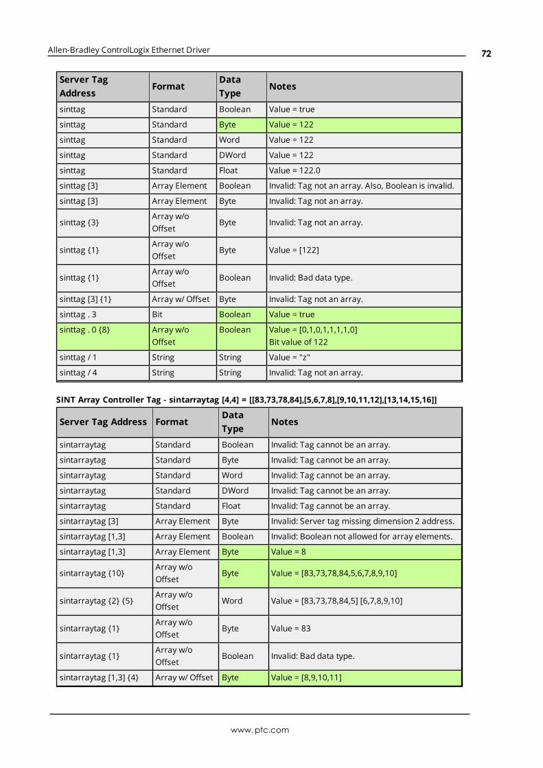
Allen-Bradley ControlLogix Ethernet Driver
Server TagAddress
FormatDataType
Notes
sinttag Standard Boolean Value = true
sinttag Standard Byte Value = 122
sinttag Standard Word Value = 122
sinttag Standard DWord Value = 122
sinttag Standard Float Value = 122.0
sinttag [3] Array Element Boolean Invalid: Tag not an array. Also, Boolean is invalid.
sinttag [3] Array Element Byte Invalid: Tag not an array.
sinttag {3}Array w/oOffset
Byte Invalid: Tag not an array.
sinttag {1}Array w/oOffset
Byte Value = [122]
sinttag {1}Array w/oOffset
Boolean Invalid: Bad data type.
sinttag [3] {1} Array w/ Offset Byte Invalid: Tag not an array.
sinttag . 3 Bit Boolean Value = true
sinttag . 0 {8} Array w/oOffset
Boolean Value = [0,1,0,1,1,1,1,0]Bit value of 122
sinttag / 1 String String Value = "z"
sinttag / 4 String String Invalid: Tag not an array.
SINT Array Controller Tag - sintarraytag [4,4] = [[83,73,78,84],[5,6,7,8],[9,10,11,12],[13,14,15,16]]
Server Tag Address FormatDataType
Notes
sintarraytag Standard Boolean Invalid: Tag cannot be an array.
sintarraytag Standard Byte Invalid: Tag cannot be an array.
sintarraytag Standard Word Invalid: Tag cannot be an array.
sintarraytag Standard DWord Invalid: Tag cannot be an array.
sintarraytag Standard Float Invalid: Tag cannot be an array.
sintarraytag [3] Array Element Byte Invalid: Server tag missing dimension 2 address.
sintarraytag [1,3] Array Element Boolean Invalid: Boolean not allowed for array elements.
sintarraytag [1,3] Array Element Byte Value = 8
sintarraytag {10}Array w/oOffset
Byte Value = [83,73,78,84,5,6,7,8,9,10]
sintarraytag {2} {5}Array w/oOffset
Word Value = [83,73,78,84,5] [6,7,8,9,10]
sintarraytag {1}Array w/oOffset
Byte Value = 83
sintarraytag {1}Array w/oOffset
Boolean Invalid: Bad data type.
sintarraytag [1,3] {4} Array w/ Offset Byte Value = [8,9,10,11]
www.ptc.com
72

Allen-Bradley ControlLogix Ethernet Driver
Server Tag Address FormatDataType
Notes
sintarraytag . 3 Bit Boolean Invalid: Tag must reference atomic location.
sintarraytag [1,3] . 3 Bit Boolean Value = 1
sintarraytag [1,3] . 0{8}
Array w/oOffset
Boolean Value = [0,0,0,1,0,0,0,0]
sintarraytag / 1 String String Value = "S"
sintarraytag / 4 String String Value = "SINT"
Advanced Addressing: INT
Format Supported Data Types Notes
StandardBoolean*, Byte, Char**, Word, Short,BCD, DWord, Long, LBCD, Float****
None
ArrayElement
Byte, Char**, Word, Short, BCD,DWord, Long, LBCD, Float****
The Controller tag must be an array.
Arrayw/oOffset
Boolean Array
1. Use this case to have the bits within an INT inarray form.
Note: This is not an array of INTs in Booleannotation.
2. Applies to bit-within-INT only. Example: tag_1.0{16}.
3. .bit + array size cannot exceed 16 bits.Example: tag_1.1{16} exceeds an INT, tag_1.0{16} does not.
Arrayw/oOffset
Byte Array, Char Array**, WordArray, Short Array, BCD Array,DWord Array, Long Array, LBCDArray***Float Array***,****
If accessing more than a single element, theController tag must be an array.
Array w/Offset
Byte Array, Char Array** WordArray, Short Array, BCD Array,DWord Array, Long Array, LBCDArray***, Float Array***,****
The Controller tag must be an array.
Bit Boolean
1. The range is limited from 0 to 15.
2. If the Controller tag is an array, the bit classreference must be prefixed by an arrayelement class reference. Example: tag_1[2,2,3].0.
String String
1. If accessing a single element, the Controllertag need not be an array.
Note: The value of the string is the ASCIIequivalent of the INT value (clamped to 255).Example: INT = 65 dec = "A".
www.ptc.com
73

Allen-Bradley ControlLogix Ethernet Driver
Format Supported Data Types Notes
2. If accessing more than a single element, theController tag must be an array. The value ofthe string is the null-terminated ASCIIequivalent of all the INTs (clamped to 255) inthe string.
1 character in string = 1 INT, clamped to 255
INT strings are not packed. For greaterefficiency, use SINT strings or the STRINGstructure instead.
*non-zero values are clamped to true.**Values exceeding 255 are clamped to 255.***Each element of the array corresponds to an element in the INT array. Arrays are not packed.****Float value equals the face value of Controller tag in float form (non-IEEE floating-point number).
ExamplesExamples highlighted signify common use cases.
INT Controller Tag - inttag = 65534 (decimal)
Server Tag Address ClassDataType
Notes
inttag Standard Boolean Value = true
inttag Standard Byte Value = 255
inttag Standard Word Value = 65534
inttag Standard DWord Value = 65534
inttag Standard Float Value = 65534.0
inttag [3] Array Element Boolean Invalid: Tag not an array. Boolean is invalid.
inttag [3] Array Element Word Invalid: Tag not an array.
inttag {3} Array w/o Offset Word Invalid: Tag not an array.
inttag {1} Array w/o Offset Word Value = [65534]
inttag {1} Array w/o Offset Boolean Invalid: Bad data type.
inttag [3] {1} Array w/ Offset Word Invalid: Tag not an array.
inttag . 3 Bit Boolean Value = true
inttag . 0 {16} Array w/o Offset Boolean Value = [0,1,1,1,1,1,1,1,1,1,1,1,1,1,1,1]Bit value of 65534
inttag / 1 String String Value = unprintable character = 255 decimal.
inttag / 4 String String Invalid: Tag not an array.
INT Array Controller Tag - intarraytag [4,4] = [[73,78,84,255],[256,257,258,259],[9,10,11,12],[13,14,15,16]]
www.ptc.com
74

Allen-Bradley ControlLogix Ethernet Driver
Server Tag Address ClassDataType
Notes
intarraytag Standard Boolean Invalid: Tag cannot be an array.
intarraytag Standard Byte Invalid: Tag cannot be an array.
intarraytag Standard Word Invalid: Tag cannot be an array.
intarraytag Standard DWord Invalid: Tag cannot be an array.
intarraytag Standard Float Invalid: Tag cannot be an array.
intarraytag [3] Array Element Word Invalid: Server tag missing dimension 2 address.
intarraytag [1,3] Array Element Boolean Invalid: Boolean not allowed for array elements.
intarraytag [1,3] Array Element Word Value = 259
intarraytag {10}Array w/oOffset
Byte Value = [73,78,84,255,255,255,255,255,9,10]
intarraytag {2} {5}Array w/oOffset
Word Value = [73,78,84,255,256] [257,258,259,9,10]
intarraytag {1}Array w/oOffset
Word Value = 73
intarraytag {1}Array w/oOffset
Boolean Invalid: Bad data type.
intarraytag [1,3] {4} Array w/ Offset Word Value = [259,9,10,11]
intarraytag . 3 Bit Boolean Invalid: Tag must reference atomic location.
intarraytag [1,3] . 3 Bit Boolean Value = 0
intarraytag [1,3] . 0{16}
Array w/oOffset
Boolean Value = [1,1,0,0,0,0,0,0,1,0,0,0,0,0,0,0]Bit value for 259
intarraytag / 1 String String Value = "I"
intarraytag / 3 String String Value = "INT"
Advanced Addressing: DINT
Format Supported Data Types Notes
StandardBoolean*, Byte, Char**, Word,Short, BCD***, DWord, Long, LBCD,Float ****
None
ArrayElement
Byte, Char**, Word, Short, BCD***,DWord, Long, LBCD, Float ****
The Controller tag must be an array.
Arrayw/oOffset
Boolean Array
1. Use this case to have the bits within an DINT inarray form.
Note: This is not an array of DINTs in Booleannotation.
2. Applies to bit-within-DINT only. Example: tag_1.0{32}.
3. .bit + array size cannot exceed 32 bits. Example:tag_1.1{32} exceeds an DINT, tag_1.0{32} does
www.ptc.com
75

Allen-Bradley ControlLogix Ethernet Driver
Format Supported Data Types Notes
not.
Arrayw/oOffset
Byte Array, Char Array**, WordArray, Short Array, BCD Array***,DWord Array, Long Array, LBCDArray, Float Array ****
If accessing more than a single element, the Controllertag must be an array.
Array w/Offset
Byte Array, Char Array**, WordArray, Short Array, BCD Array***,DWord Array, Long Array, LBCDArray, Float Array ****
The Controller tag must be an array.
Bit Boolean
1. The range is limited from 0 to 31.
2. If Controller tag is an array, bit class referencemust be prefixed by an array element classreference. Example: tag_1 [2,2,3].0.
String String
1. If accessing a single element, the Controller tagneed not be an array.
Note: The value of the string is the ASCIIequivalent of the DINT value (clamped to 255).Example: SINT = 65dec = "A".
2. If accessing more than a single element, theController tag must be an array. The value ofthe string is the null-terminated ASCIIequivalent of all the DINTs (clamped to 255) inthe string.
1 character in string = 1 DINT, clamped to 255
Note: DINT strings are not packed. For greaterefficiency, use SINT strings or the STRINGstructure instead.
*non-zero values are clamped to true.**Values exceeding 255 are clamped to 255.***Values exceeding 65535 are clamped to 65535.****Float value equals the face value of Controller tag in float form (non-IEEE floating-point number).
ExamplesExamples highlighted signify common use cases.
DINT Controller Tag - dinttag = 70000 (decimal)
Server Tag Address Format DataType
Notes
dinttag Standard Boolean Value = true
dinttag Standard Byte Value = 255
dinttag Standard Word Value = 65535
www.ptc.com
76
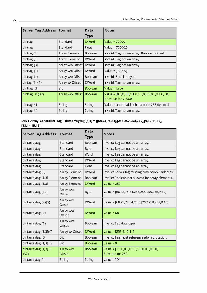
Allen-Bradley ControlLogix Ethernet Driver
Server Tag Address Format DataType
Notes
dinttag Standard DWord Value = 70000
dinttag Standard Float Value = 70000.0
dinttag [3] Array Element Boolean Invalid: Tag not an array. Boolean is invalid.
dinttag [3] Array Element DWord Invalid: Tag not an array.
dinttag {3} Array w/o Offset DWord Invalid: Tag not an array.
dinttag {1} Array w/o Offset DWord Value = [70000]
dinttag {1} Array w/o Offset Boolean Invalid: Bad data type
dintag [3] {1} Array w/ Offset DWord Invalid: Tag not an array.
dinttag . 3 Bit Boolean Value = false
dinttag . 0 {32} Array w/o Offset Boolean Value = [0,0,0,0,1,1,1,0,1,0,0,0,1,0,0,0,1,0,...0]Bit value for 70000
dinttag / 1 String String Value = unprintable character = 255 decimal
dinttag / 4 String String Invalid: Tag not an array.
DINT Array Controller Tag - dintarraytag [4,4] = [[68,73,78,84],[256,257,258,259],[9,10,11,12],[13,14,15,16]]
Server Tag Address FormatDataType
Notes
dintarraytag Standard Boolean Invalid: Tag cannot be an array.
dintarraytag Standard Byte Invalid: Tag cannot be an array.
dintarraytag Standard Word Invalid: Tag cannot be an array.
dintarraytag Standard DWord Invalid: Tag cannot be an array.
dintarraytag Standard Float Invalid: Tag cannot be an array.
dintarraytag [3] Array Element DWord Invalid: Server tag missing dimension 2 address.
dintarraytag [1,3] Array Element Boolean Invalid: Boolean not allowed for array elements.
dintarraytag [1,3] Array Element DWord Value = 259
dintarraytag {10}Array w/oOffset
Byte Value = [68,73,78,84,255,255,255,255,9,10]
dintarraytag {2}{5}Array w/oOffset
DWord Value = [68,73,78,84,256] [257,258,259,9,10]
dintarraytag {1}Array w/oOffset
DWord Value = 68
dintarraytag {1}Array w/oOffset
Boolean Invalid: Bad data type.
dintarraytag [1,3]{4} Array w/ Offset DWord Value = [259,9,10,11]
dintarraytag . 3 Bit Boolean Invalid: Tag must reference atomic location.
dintarraytag [1,3] . 3 Bit Boolean Value = 0
dintarraytag [1,3] .0{32}
Array w/oOffset
Boolean Value = [1,1,0,0,0,0,0,0,1,0,0,0,0,0,0,0]Bit value for 259
dintarraytag / 1 String String Value = "D"
www.ptc.com
77

Allen-Bradley ControlLogix Ethernet Driver
Server Tag Address FormatDataType
Notes
dintarraytag / 3 String String Value = "DINT"
Advanced Addressing: LINT
FormatSupported DataTypes
Notes
Standard Double*, Date** None
ArrayElement
Double*, Date** The Controller tag must be an array.
Array w/oOffset
Double, Array*If accessing more than a single element, the Controller tag mustbe an array.
Array w/Offset
Double, Array* The Controller tag must be an array.
Bit N/A Not supported.
String N/A Not supported.
*Double value equals face value of Controller tag in float form (non-IEEE floating-point number).**Date values are in universal time (UTC), not localized time.
ExamplesExamples highlighted signify common use cases.
LINT Controller Tag - linttag = 2007-01-01T16:46:40.000 (date) == 1.16767E+15 (decimal)
Server Tag Address Format Data Type Notes
linttag Standard Boolean Invalid: Boolean not supported.
linttag Standard Byte Invalid: Byte not supported.
linttag Standard Word Invalid: Word not supported.
linttag Standard Double Value = 1.16767E+15
linttag Standard Date Value = 2007-01-01T16:46:40.000*
linttag [3] Array Element Boolean Invalid: Tag not an array. Boolean is invalid.
linttag [3] Array Element Double Invalid: Tag not an array.
linttag {3} Array w/o Offset Double Invalid: Tag not an array.
linttag {1} Array w/o Offset Double Value = [1.16767E+15]
linttag {1} Array w/o Offset Boolean Invalid: Bad data type.
lintag [3] {1} Array w/ Offset Double Invalid: Tag not an array.
linttag . 3 Bit Boolean Invalid: Syntax/data type not supported.
linttag / 1 String String Invalid: Syntax/data type not supported.
*Date values are in universal time (UTC), not localized time.
LINT Array Controller Tag -dintarraytag [2,2] = [0, 1.16767E+15],[9.4666E+14, 9.46746E+14] where:
www.ptc.com
78

Allen-Bradley ControlLogix Ethernet Driver
1.16767E+15 == 2007-01-01T16:46:40.000 (date)9.4666E+14 == 1999-12-31T17:06:40.0009.46746E+14 == 2000-01-1T17:00:00.0000 == 1970-01-01T00:00:00.000
Server TagAddress
FormatDataType
Notes
lintarraytag Standard Boolean Invalid: Boolean not supported.
lintarraytag Standard Byte Invalid: Byte not supported.
lintarraytag Standard Word Invalid: Word not supported.
lintarraytag Standard Double Invalid: Tag cannot be an array.
lintarraytag Standard Date Invalid: Tag cannot be an array.
lintarraytag [1] Array Element Double Invalid: Server tag missing dimension 2 address.
lintarraytag [1,1] Array Element Boolean Invalid: Boolean not allowed for array elements.
lintarraytag [1,1] Array Element Double Value = 9.46746E+14
lintarraytag [1,1] Array Element Date Value = 2000-01-01T17:00:00.000*
lintarraytag {4}Array w/oOffset
DoubleValue = [0, 1.16767E+15, 9.4666E+14,9.46746E+14]
lintarraytag {2} {2}Array w/oOffset
DoubleValue = [0, 1.16767E+15][ 9.4666E+14,9.46746E+14]
lintarraytag {4}Array w/oOffset
Date Invalid: Date array not supported.
lintarraytag {1}Array w/oOffset
Double Value = 0
lintarraytag {1}Array w/oOffset
Boolean Invalid: Bad data type.
lintarraytag [0,1] {2} Array w/ Offset Double Value = [1.16767E+15, 9.4666E+14]
lintarraytag . 3 Bit Boolean Invalid: Syntax/data type not supported.
lintarraytag / 1 String String Invalid: Syntax/data type not supported.
*Date values are in universal time (UTC), not localized time.
Advanced Addressing: REAL
Format Supported Data Types Notes
StandardBoolean*, Byte, Char**, Word,Short, BCD***, DWord, Long,LBCD, Float****
None
ArrayElement
Byte, Char**, Word, Short,BCD***, DWord, Long, LBCD,Float****
The Controller tag must be an array.
Arrayw/oOffset
Boolean Array
1. Use this case to have the bits within an REAL in arrayform.
Note: This is not an array of REALs in Boolean
www.ptc.com
79

Allen-Bradley ControlLogix Ethernet Driver
Format Supported Data Types Notes
notation.
2. Applies to bit-within-REAL only. Example: tag_1.0{32}.
3. .bit + array size cannot exceed 32 bits. Example: tag_1.1{32} exceeds an REAL, tag_1.0{32} does not.
Arrayw/oOffset
Byte Array, Char Array**,Word Array, Short Array, BCDArray***, DWord Array, LongArray, LBCD Array, FloatArray****
If accessing more than a single element, the Controller tagmust be an array.
Array w/Offset
Byte Array, Char Array**,Word Array, Short Array, BCDArray***, DWord Array, LongArray, LBCD Array, FloatArray****
The Controller tag must be an array.
Bit Boolean
1. The range is limited from 0 to 31.
2. If the Controller tag is an array, the bit classreference must be prefixed by an array elementclass reference. Example: tag_1 [2,2,3].0.
Note: Float is casted to a DWord to allowreferencing of bits.
String String
1. If accessing a single element, the Controller tag neednot be an array.
Note: The value of the string is the ASCII equivalentof the REAL value (clamped to 255). Example: SINT =65 dec = "A".
2. If accessing more than a single element, theController tag must be an array. The value of thestring is the null-terminated ASCII equivalent of allthe REALs (clamped to 255) in the string. 1 characterin string = 1 REAL, clamped to 255.
Note: REAL strings are not packed. For greaterefficiency, use SINT strings or the STRING structureinstead.
*non-zero values are clamped to true.**Values exceeding 255 are clamped to 255.***Values exceeding 65535 are clamped to 65535.****Float value is a valid IEEE single precision floating point number.
ExamplesExamples highlighted signify common use cases.
REAL Controller Tag - realtag = 512.5 (decimal)
www.ptc.com
80

Allen-Bradley ControlLogix Ethernet Driver
Server TagAddress
FormatDataType
Notes
realtag Standard Boolean Value = true
realtag Standard Byte Value = 255
realtag Standard Word Value = 512
realtag Standard DWord Value = 512
realtag Standard Float Value = 512.5
realtag [3] Array Element Boolean Invalid: Tag not an array. Also, Boolean is invalid.
realtag [3] Array Element DWord Invalid: Tag not an array.
realtag {3}Array w/oOffset
DWord Invalid: Tag not an array.
realtag {1}Array w/oOffset
Float Value = [512.5]
realtag {1}Array w/oOffset
Boolean Invalid: Bad data type.
realtag [3] {1} Array w/ Offset Float Invalid: Tag not an array.
realtag . 3 Bit Boolean Value = true
realtag . 0 {32}Array w/oOffset
BooleanValue = [0,0,0,0,0,0,0,0,0,1,0,0,0,0,0,0,...0]Bit value for 512
realtag / 1 String String Value = unprintable character = 255 decimal
realtag / 4 String String Invalid: Tag not an array.
REAL Array Controller Tag - realarraytag [4,4] = [[82.1,69.2,65.3,76.4],[256.5,257.6,258.7,259.8],[9.0,10.0,11.0,12.0],[13.0,14.0,15.0,16.0]]
Server TagAddress
FormatDataType
Notes
realarraytag Standard Boolean Invalid: Tag cannot be an array.
realarraytag Standard Byte Invalid: Tag cannot be an array.
realarraytag Standard Word Invalid: Tag cannot be an array.
realarraytag Standard DWord Invalid: Tag cannot be an array.
realarraytag Standard Float Invalid: Tag cannot be an array.
realarraytag [3]ArrayElement
Float Invalid: Server tag missing dimension 2 address.
realarraytag [1,3]ArrayElement
Boolean Invalid: Boolean not allowed for array elements.
realarraytag [1,3] ArrayElement
Float Value = 259.8
realarraytag {10}Array w/oOffset
Byte Value = [82,69,65,76,255,255,255,255,9,10]
realarraytag {2} {5} Array w/oOffset
Float Value = [82.1,69.2,65.3,76.4,256.5][257.6,258.7,259.8,9,10]
realarraytag {1}Array w/oOffset
Float Value = 82.1
www.ptc.com
81
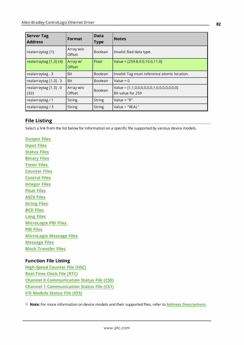
Allen-Bradley ControlLogix Ethernet Driver
Server TagAddress
FormatDataType
Notes
realarraytag {1}Array w/oOffset
Boolean Invalid: Bad data type.
realarraytag [1,3] {4} Array w/Offset
Float Value = [259.8,9.0,10.0,11.0]
realarraytag . 3 Bit Boolean Invalid: Tag must reference atomic location.
realarraytag [1,3] . 3 Bit Boolean Value = 0
realarraytag [1,3] . 0{32}
Array w/oOffset
BooleanValue = [1,1,0,0,0,0,0,0,1,0,0,0,0,0,0,0]Bit value for 259
realarraytag / 1 String String Value = "R"
realarraytag / 3 String String Value = "REAL"
File ListingSelect a link from the list below for information on a specific file supported by various device models.
Output FilesInput FilesStatus FilesBinary FilesTimer FilesCounter FilesControl FilesInteger FilesFloat FilesASCII FilesString FilesBCD FilesLong FilesMicroLogix PID FilesPID FilesMicroLogix Message FilesMessage FilesBlock Transfer Files
Function File ListingHigh-Speed Counter File (HSC)Real-Time Clock File (RTC)Channel 0 Communication Status File (CS0)Channel 1 Communication Status File (CS1)I/O Module Status File (IOS)
Note: For more information on device models and their supported files, refer to Address Descriptions.
www.ptc.com
82

Allen-Bradley ControlLogix Ethernet Driver
Output FilesThe syntax for accessing data in the output file differs depending on the PLC model. Arrays are notsupported for output files. The default data types are shown in bold.
PLC-5 SyntaxSyntax Data Type Access
O:<word> Short, Word, BCD Read/Write
O:<word>/<bit> Boolean Read/Write
O/bit Boolean Read/Write
Note: Word and bit address information is in octal for PLC-5 models. This follows the convention of theprogramming software.
MicroLogix SyntaxSyntax Data Type Access
O:<word> Short, Word, BCD Read/Write
O:<word>/<bit> Boolean Read/Write
O/bit Boolean Read/Write
MicroLogix models have two types of I/O: embedded I/O and expansion I/O (not applicable for MicroLogix1000). Embedded I/O resides with the CPU base unit while Expansion I/O plugs into the CPU base unit. Thetable below lists the I/O capabilities of each MicroLogix model.
MicroLogix Model Embedded I/O Expansion I/O
1000 Slot 0 N/A
1100 Slot 0 Slots 1-4
1200 Slot 0 Slots 1-6
1400 Slot 0 Slots 1-7
1500 Slot 0 Slots 1-16
The address syntax for MicroLogix I/O references a zero-based word offset, not a slot. Users mustdetermine the word offset to a particular slot. This requires knowledge of the modules and their respectivesize in words. The table below specifies the size of some available modules; however, it is recommendedthat users consult both the MicroLogix documentation and the controller project to determine the module'strue word size.
MicroLogix Embedded I/O Word SizesMicroLogix Model # Input Words # Output Words
1000 2 1
1100 6 4
1200 4 4
1400 8 6
1500 4 4
www.ptc.com
83
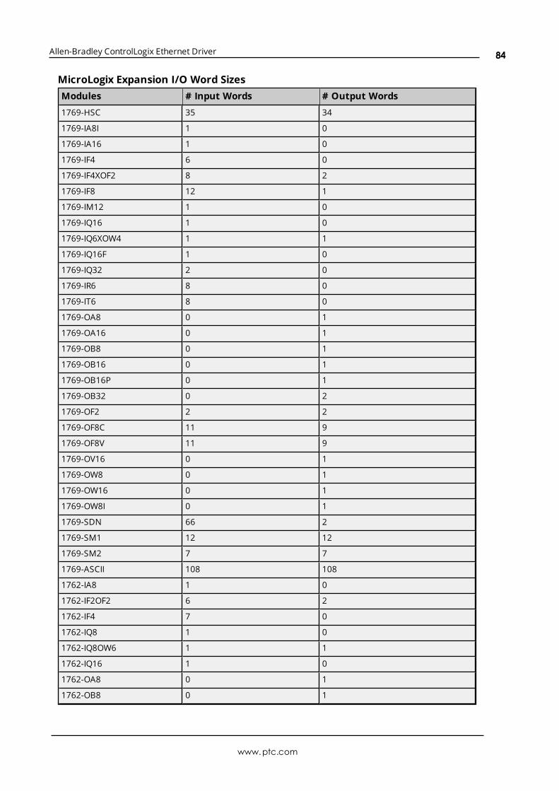
Allen-Bradley ControlLogix Ethernet Driver
MicroLogix Expansion I/O Word SizesModules # Input Words # Output Words
1769-HSC 35 34
1769-IA8I 1 0
1769-IA16 1 0
1769-IF4 6 0
1769-IF4XOF2 8 2
1769-IF8 12 1
1769-IM12 1 0
1769-IQ16 1 0
1769-IQ6XOW4 1 1
1769-IQ16F 1 0
1769-IQ32 2 0
1769-IR6 8 0
1769-IT6 8 0
1769-OA8 0 1
1769-OA16 0 1
1769-OB8 0 1
1769-OB16 0 1
1769-OB16P 0 1
1769-OB32 0 2
1769-OF2 2 2
1769-OF8C 11 9
1769-OF8V 11 9
1769-OV16 0 1
1769-OW8 0 1
1769-OW16 0 1
1769-OW8I 0 1
1769-SDN 66 2
1769-SM1 12 12
1769-SM2 7 7
1769-ASCII 108 108
1762-IA8 1 0
1762-IF2OF2 6 2
1762-IF4 7 0
1762-IQ8 1 0
1762-IQ8OW6 1 1
1762-IQ16 1 0
1762-OA8 0 1
1762-OB8 0 1
www.ptc.com
84
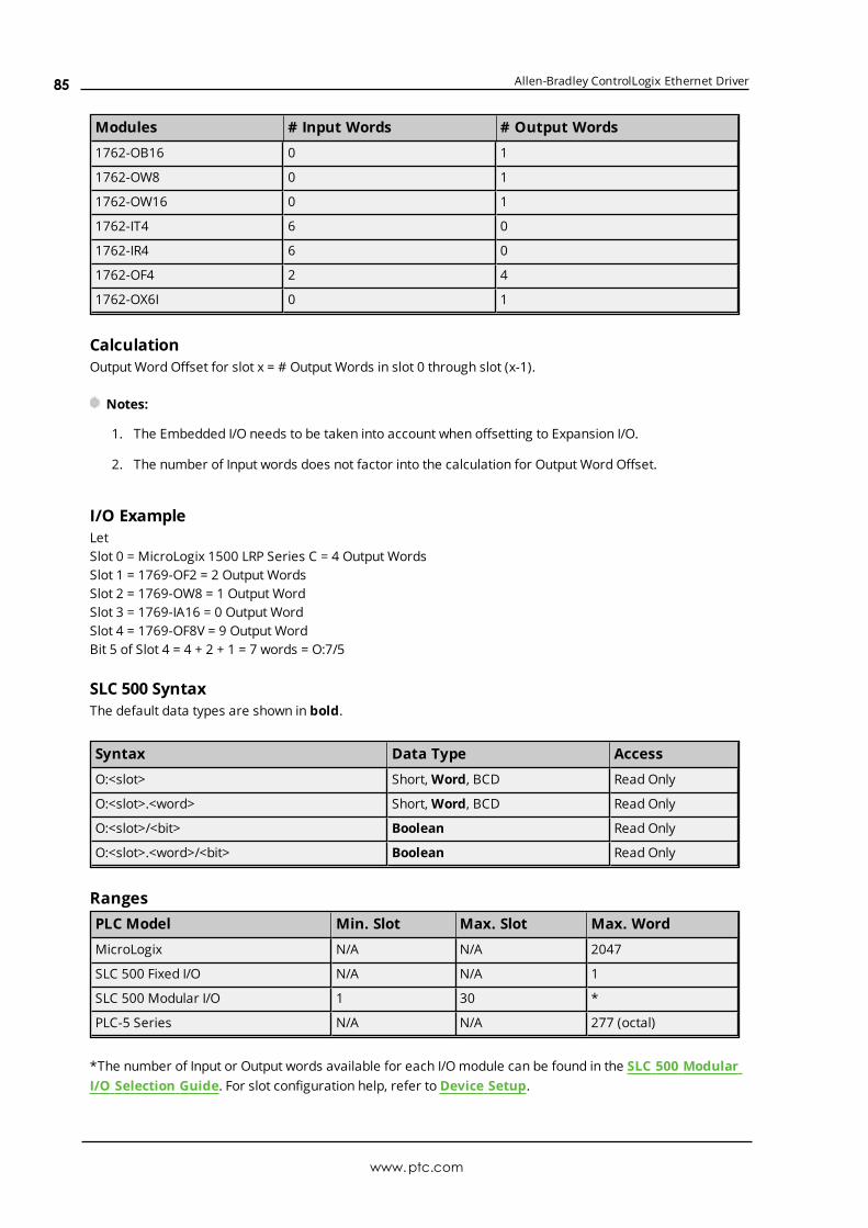
Allen-Bradley ControlLogix Ethernet Driver
Modules # Input Words # Output Words
1762-OB16 0 1
1762-OW8 0 1
1762-OW16 0 1
1762-IT4 6 0
1762-IR4 6 0
1762-OF4 2 4
1762-OX6I 0 1
CalculationOutput Word Offset for slot x = # Output Words in slot 0 through slot (x-1).
Notes:
1. The Embedded I/O needs to be taken into account when offsetting to Expansion I/O.
2. The number of Input words does not factor into the calculation for Output Word Offset.
I/O ExampleLetSlot 0 = MicroLogix 1500 LRP Series C = 4 Output WordsSlot 1 = 1769-OF2 = 2 Output WordsSlot 2 = 1769-OW8 = 1 Output WordSlot 3 = 1769-IA16 = 0 Output WordSlot 4 = 1769-OF8V = 9 Output WordBit 5 of Slot 4 = 4 + 2 + 1 = 7 words = O:7/5
SLC 500 SyntaxThe default data types are shown in bold.
Syntax Data Type Access
O:<slot> Short, Word, BCD Read Only
O:<slot>.<word> Short, Word, BCD Read Only
O:<slot>/<bit> Boolean Read Only
O:<slot>.<word>/<bit> Boolean Read Only
RangesPLC Model Min. Slot Max. Slot Max. Word
MicroLogix N/A N/A 2047
SLC 500 Fixed I/O N/A N/A 1
SLC 500 Modular I/O 1 30 *
PLC-5 Series N/A N/A 277 (octal)
*The number of Input or Output words available for each I/O module can be found in the SLC 500 ModularI/O Selection Guide. For slot configuration help, refer to Device Setup.
www.ptc.com
85
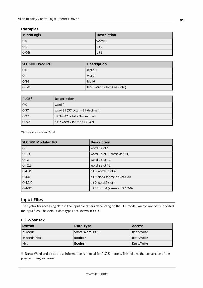
Allen-Bradley ControlLogix Ethernet Driver
ExamplesMicroLogix Description
O:0 word 0
O/2 bit 2
O:0/5 bit 5
SLC 500 Fixed I/O Description
O:0 word 0
O:1 word 1
O/16 bit 16
O:1/0 bit 0 word 1 (same as O/16)
PLC5* Description
O:0 word 0
O:37 word 31 (37 octal = 31 decimal)
O/42 bit 34 (42 octal = 34 decimal)
O:2/2 bit 2 word 2 (same as O/42)
*Addresses are in Octal.
SLC 500 Modular I/O Description
O:1 word 0 slot 1
O:1.0 word 0 slot 1 (same as O:1)
O:12 word 0 slot 12
O:12.2 word 2 slot 12
O:4.0/0 bit 0 word 0 slot 4
O:4/0 bit 0 slot 4 (same as O:4.0/0)
O:4.2/0 bit 0 word 2 slot 4
O:4/32 bit 32 slot 4 (same as O:4.2/0)
Input FilesThe syntax for accessing data in the input file differs depending on the PLC model. Arrays are not supportedfor input files. The default data types are shown in bold.
PLC-5 SyntaxSyntax Data Type Access
I:<word> Short, Word, BCD Read/Write
I:<word>/<bit> Boolean Read/Write
I/bit Boolean Read/Write
Note: Word and bit address information is in octal for PLC-5 models. This follows the convention of theprogramming software.
www.ptc.com
86

Allen-Bradley ControlLogix Ethernet Driver
MicroLogix SyntaxSyntax Data Type Access
I:<word> Short, Word, BCD Read/Write
I:<word>/<bit> Boolean Read/Write
I/bit Boolean Read/Write
MicroLogix models have two types of I/O: embedded I/O and expansion I/O (not applicable for MicroLogix1000). Embedded I/O resides with the CPU base unit while Expansion I/O plugs into the CPU base unit. Thetable below lists the I/O capabilities of each MicroLogix model.
MicroLogix Model Embedded I/O Expansion I/O
1000 Slot 0 N/A
1100 Slot 0 Slots 1-4
1200 Slot 0 Slots 1-6
1400 Slot 0 Slots 1-7
1500 Slot 0 Slots 1-16
The address syntax for MicroLogix I/O references a zero-based word offset, not a slot. Users mustdetermine the word offset to a particular slot. This requires knowledge of the modules and their respectivesize in words. The table below specifies the size of some available modules; however, it is recommendedthat the MicroLogix documentation and controller project be consulted to determine a module's true wordsize.
MicroLogix Embedded I/O Word SizesMicroLogix Model # Input Words # Output Words
1000 2 1
1100 6 4
1200 4 4
1400 8 6
1500 4 4
MicroLogix Expansion I/O Word SizesModules # Input Words # Output Words
1769-HSC 35 34
1769-IA8I 1 0
1769-IA16 1 0
1769-IF4 6 0
1769-IF4XOF2 8 2
1769-IF8 12 1
1769-IM12 1 0
1769-IQ16 1 0
1769-IQ6XOW4 1 1
www.ptc.com
87

Allen-Bradley ControlLogix Ethernet Driver
Modules # Input Words # Output Words
1769-IQ16F 1 0
1769-IQ32 2 0
1769-IR6 8 0
1769-IT6 8 0
1769-OA8 0 1
1769-OA16 0 1
1769-OB8 0 1
1769-OB16 0 1
1769-OB16P 0 1
1769-OB32 0 2
1769-OF2 2 2
1769-OF8C 11 9
1769-OF8V 11 9
1769-OV16 0 1
1769-OW8 0 1
1769-OW16 0 1
1769-OW8I 0 1
1769-SDN 66 2
1769-SM1 12 12
1769-SM2 7 7
1769-ASCII 108 108
1762-IA8 1 0
1762-IF2OF2 6 2
1762-IF4 7 0
1762-IQ8 1 0
1762-IQ8OW6 1 1
1762-IQ16 1 0
1762-OA8 0 1
1762-OB8 0 1
1762-OB16 0 1
1762-OW8 0 1
1762-OW16 0 1
1762-IT4 6 0
1762-IR4 6 0
1762-OF4 2 4
1762-OX6I 0 1
CalculationInput Word Offset for slot x = # Input Words in slot 0 through slot (x-1).
Notes:
www.ptc.com
88

Allen-Bradley ControlLogix Ethernet Driver
1. The Embedded I/O needs to be taken into account when offsetting to Expansion I/O.
2. The number of Output words does not factor into the calculation for Input Word Offset.
I/O ExampleLetSlot 0 = MicroLogix 1500 LRP Series C = 4 Input WordsSlot 1 = 1769-OF2 = 2 Input WordsSlot 2 = 1769-OW8 = 0 Input WordSlot 3 = 1769-IA16 = 1 Input WordSlot 4 = 1769-OF8V = 11 Input WordBit 5 of Slot 3 = 4 + 2 = 6 words = I:6/5
SLC 500 SyntaxSyntax Data Type Access
I:<slot> Short, Word, BCD Read Only
I:<slot>.<word> Short, Word, BCD Read Only
I:<slot>/<bit> Boolean Read Only
I:<slot>.<word>/<bit> Boolean Read Only
RangesPLC Model Min. Slot Max. Slot Max. Word
MicroLogix N/A N/A 2047
SLC 500 Fixed I/O N/A N/A 1
SLC 500 Modular I/O 1 30 *
PLC-5 Series N/A N/A 277 (octal)
*The number of Input or Output words available for each I/O module can be found in the SLC 500 ModularI/O Selection Guide. For slot configuration help, refer to Device Setup.
ExamplesMicroLogix Description
I:0 Word 0
I/2 Bit 2
I:1/5 Bit 5 word 1
SLC 500 Fixed I/O Description
I:0 Word 0
I:1 Word 1
I/16 bit 16
I:1/0 Bit 0 word 1 (same as I/16)
www.ptc.com
89
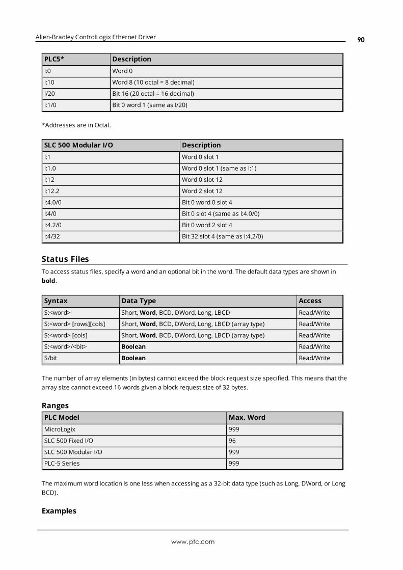
Allen-Bradley ControlLogix Ethernet Driver
PLC5* Description
I:0 Word 0
I:10 Word 8 (10 octal = 8 decimal)
I/20 Bit 16 (20 octal = 16 decimal)
I:1/0 Bit 0 word 1 (same as I/20)
*Addresses are in Octal.
SLC 500 Modular I/O Description
I:1 Word 0 slot 1
I:1.0 Word 0 slot 1 (same as I:1)
I:12 Word 0 slot 12
I:12.2 Word 2 slot 12
I:4.0/0 Bit 0 word 0 slot 4
I:4/0 Bit 0 slot 4 (same as I:4.0/0)
I:4.2/0 Bit 0 word 2 slot 4
I:4/32 Bit 32 slot 4 (same as I:4.2/0)
Status FilesTo access status files, specify a word and an optional bit in the word. The default data types are shown inbold.
Syntax Data Type Access
S:<word> Short, Word, BCD, DWord, Long, LBCD Read/Write
S:<word> [rows][cols] Short, Word, BCD, DWord, Long, LBCD (array type) Read/Write
S:<word> [cols] Short, Word, BCD, DWord, Long, LBCD (array type) Read/Write
S:<word>/<bit> Boolean Read/Write
S/bit Boolean Read/Write
The number of array elements (in bytes) cannot exceed the block request size specified. This means that thearray size cannot exceed 16 words given a block request size of 32 bytes.
RangesPLC Model Max. Word
MicroLogix 999
SLC 500 Fixed I/O 96
SLC 500 Modular I/O 999
PLC-5 Series 999
The maximum word location is one less when accessing as a 32-bit data type (such as Long, DWord, or LongBCD).
Examples
www.ptc.com
90

Allen-Bradley ControlLogix Ethernet Driver
Example Description
S:0 Word 0
S/26 Bit 26
S:4/15 Bit 15 word 4
S:10 [16] 16 element array starting at word 10
S:0 [4] [8] 4 by 8 element array starting at word 0
Binary FilesTo access binary files, specify a file number, a word and optional bit in the word. The default data types areshown in bold.
Syntax Data Type Access
B<file>:<word> Short, Word, BCD, DWord, Long, LBCD Read/Write
B<file>:<word> [rows][cols] Short, Word, BCD, DWord, Long, LBCD (array type) Read/Write
B<file>:<word> [cols] Short, Word, BCD, DWord, Long, LBCD (array type) Read/Write
B<file>:<word>/<bit> Boolean Read/Write
B<file>/bit Boolean Read/Write
The number of array elements (in bytes) cannot exceed the block request size specified. This means thatarray size cannot exceed 16 words given a block request size of 32 bytes.
RangesPLC Model File Number Max. Word
MicroLogix 3, 9-999 999
SLC 500 Fixed I/O 3, 9-255 255
SLC 500 Modular I/O 3, 9-999 999
PLC-5 Series 3-999 1999
The maximum word location is one less when accessing as a 32-bit data type (such as Long, DWord, or LongBCD).
ExamplesExample Description
B3:0 Word 0
B3/26 Bit 26
B12:4/15 Bit 15 word 4
B3:10 [20] 20 element array starting at word 10
B15:0 [6] [6] 6 by 6 element array starting at word 0
Timer FilesTimer files are a structured type whose data is accessed by specifying a file number, an element and a field.The default data types are shown in bold.
www.ptc.com
91
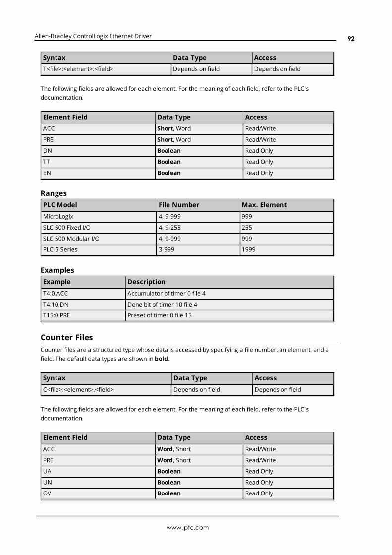
Allen-Bradley ControlLogix Ethernet Driver
Syntax Data Type Access
T<file>:<element>.<field> Depends on field Depends on field
The following fields are allowed for each element. For the meaning of each field, refer to the PLC'sdocumentation.
Element Field Data Type Access
ACC Short, Word Read/Write
PRE Short, Word Read/Write
DN Boolean Read Only
TT Boolean Read Only
EN Boolean Read Only
RangesPLC Model File Number Max. Element
MicroLogix 4, 9-999 999
SLC 500 Fixed I/O 4, 9-255 255
SLC 500 Modular I/O 4, 9-999 999
PLC-5 Series 3-999 1999
ExamplesExample Description
T4:0.ACC Accumulator of timer 0 file 4
T4:10.DN Done bit of timer 10 file 4
T15:0.PRE Preset of timer 0 file 15
Counter FilesCounter files are a structured type whose data is accessed by specifying a file number, an element, and afield. The default data types are shown in bold.
Syntax Data Type Access
C<file>:<element>.<field> Depends on field Depends on field
The following fields are allowed for each element. For the meaning of each field, refer to the PLC'sdocumentation.
Element Field Data Type Access
ACC Word, Short Read/Write
PRE Word, Short Read/Write
UA Boolean Read Only
UN Boolean Read Only
OV Boolean Read Only
www.ptc.com
92
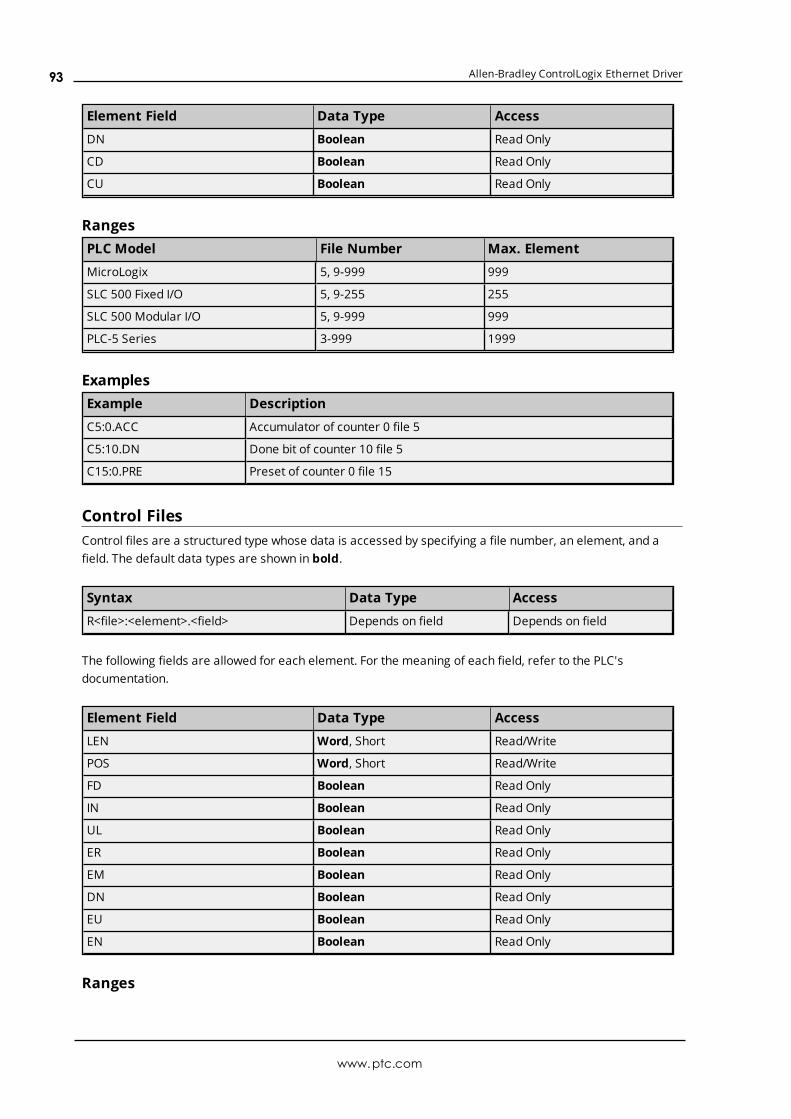
Allen-Bradley ControlLogix Ethernet Driver
Element Field Data Type Access
DN Boolean Read Only
CD Boolean Read Only
CU Boolean Read Only
RangesPLC Model File Number Max. Element
MicroLogix 5, 9-999 999
SLC 500 Fixed I/O 5, 9-255 255
SLC 500 Modular I/O 5, 9-999 999
PLC-5 Series 3-999 1999
ExamplesExample Description
C5:0.ACC Accumulator of counter 0 file 5
C5:10.DN Done bit of counter 10 file 5
C15:0.PRE Preset of counter 0 file 15
Control FilesControl files are a structured type whose data is accessed by specifying a file number, an element, and afield. The default data types are shown in bold.
Syntax Data Type Access
R<file>:<element>.<field> Depends on field Depends on field
The following fields are allowed for each element. For the meaning of each field, refer to the PLC'sdocumentation.
Element Field Data Type Access
LEN Word, Short Read/Write
POS Word, Short Read/Write
FD Boolean Read Only
IN Boolean Read Only
UL Boolean Read Only
ER Boolean Read Only
EM Boolean Read Only
DN Boolean Read Only
EU Boolean Read Only
EN Boolean Read Only
Ranges
www.ptc.com
93
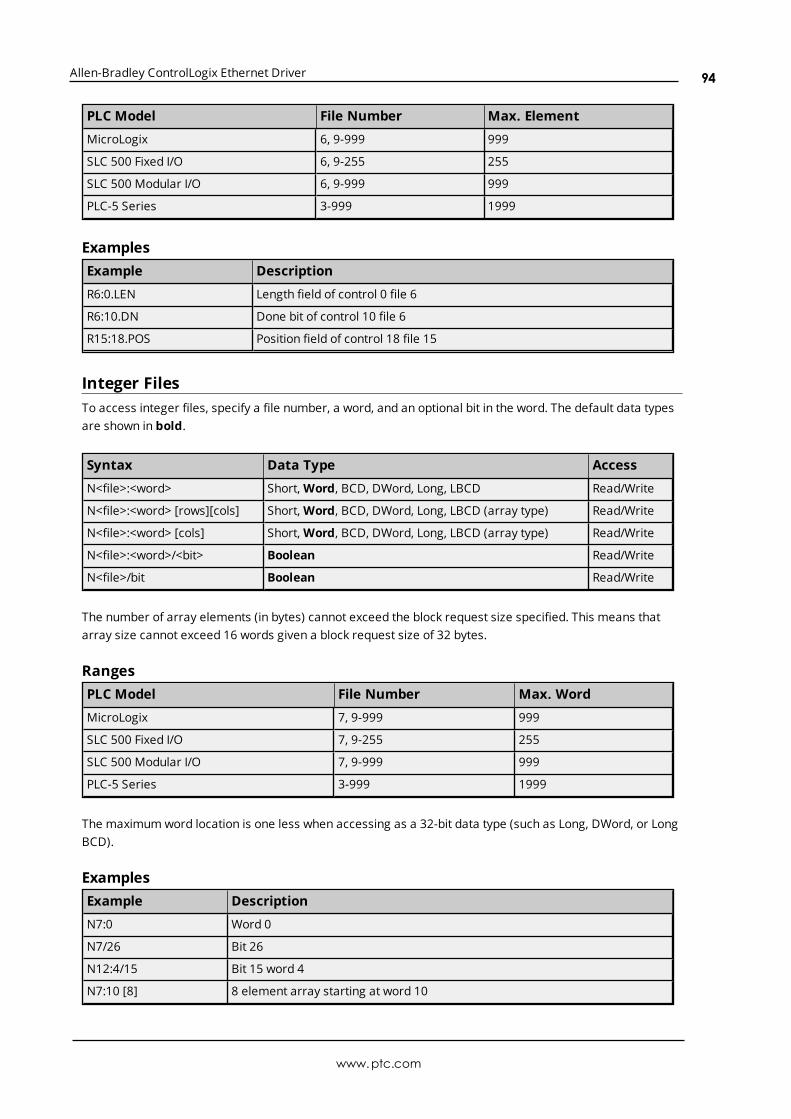
Allen-Bradley ControlLogix Ethernet Driver
PLC Model File Number Max. Element
MicroLogix 6, 9-999 999
SLC 500 Fixed I/O 6, 9-255 255
SLC 500 Modular I/O 6, 9-999 999
PLC-5 Series 3-999 1999
ExamplesExample Description
R6:0.LEN Length field of control 0 file 6
R6:10.DN Done bit of control 10 file 6
R15:18.POS Position field of control 18 file 15
Integer FilesTo access integer files, specify a file number, a word, and an optional bit in the word. The default data typesare shown in bold.
Syntax Data Type Access
N<file>:<word> Short, Word, BCD, DWord, Long, LBCD Read/Write
N<file>:<word> [rows][cols] Short, Word, BCD, DWord, Long, LBCD (array type) Read/Write
N<file>:<word> [cols] Short, Word, BCD, DWord, Long, LBCD (array type) Read/Write
N<file>:<word>/<bit> Boolean Read/Write
N<file>/bit Boolean Read/Write
The number of array elements (in bytes) cannot exceed the block request size specified. This means thatarray size cannot exceed 16 words given a block request size of 32 bytes.
RangesPLC Model File Number Max. Word
MicroLogix 7, 9-999 999
SLC 500 Fixed I/O 7, 9-255 255
SLC 500 Modular I/O 7, 9-999 999
PLC-5 Series 3-999 1999
The maximum word location is one less when accessing as a 32-bit data type (such as Long, DWord, or LongBCD).
ExamplesExample Description
N7:0 Word 0
N7/26 Bit 26
N12:4/15 Bit 15 word 4
N7:10 [8] 8 element array starting at word 10
www.ptc.com
94

Allen-Bradley ControlLogix Ethernet Driver
Example Description
N15:0 [4] [5] 4 by 5 element array starting at word 0
Float FilesTo access float files, specify a file number and an element. The default data types are shown in bold.
Syntax Data Type Access
F<file>:<element> Float Read/Write
F<file>:<element> [rows][cols] Float (array type) Read/Write
F<file>:<element> [cols] Float (array type) Read/Write
The number of array elements (in bytes) cannot exceed the block request size specified. This means thatarray size cannot exceed 8 floats given a block request size of 32 bytes.
RangesPLC Model File Number Max. Word
MicroLogix 8-999 999
SLC 500 Fixed I/O N/A N/A
SLC 500 Modular I/O 8-999 999
PLC-5 Series 3-999 1999
ExamplesExample Description
F8:0 Float 0
F8:10 [16] 16 element array starting at word 10
F15:0 [4] [4] 16 element array starting at word 0
ASCII FilesTo access ASCII file data, specify a file number and a character location. The default data types are shown inbold.
Syntax Data Type Access
A<file>:<char> Char, Byte* Read/Write
A<file>:<char> [rows][cols] Char, Byte* Read/Write
A<file>:<char> [cols] Char, Byte* Read/Write
A<file>:<word offset>/length String** Read/Write
*The number of array elements cannot exceed the block request size specified. Internally, the PLC packs twocharacters per word in the file, with the high byte containing the first character and the low byte containingthe second character. The PLC programming software allows access at the word level or two-characterlevel. TheAllen-Bradley ControlLogix Ethernet Driver allows accessing to the character level.
www.ptc.com
95

Allen-Bradley ControlLogix Ethernet Driver
Using the programming software, "A10:0 = AB," would result in 'A' being stored in the high byte of A10:0 and'B' being stored in the low byte. Using the Allen-Bradley ControlLogix Ethernet Driver, two assignmentswould be made: "A10:0 = A" and "A10:1 = B." This would result in the same data being stored in the PLCmemory.
**Referencing this file as string data allows access to data at word boundaries like the programmingsoftware. The length can be up to 232 characters. If a string that is sent to the device is smaller in lengththan the length specified by the address, the driver null terminates the string before sending it down to thecontroller.
RangesPLC Model File Number Max. Character
MicroLogix 3-255 511
SLC 500 Fixed I/O N/A N/A
SLC 500 Modular I/O 9-999 1999
PLC-5 Series 3-999 1999
Note: Not all MicroLogix and SLC 500 PLC devices support ASCII file types. For more information, refer tothe PLC's documentation.
ExamplesExample Description
A9:0 character 0 (high byte of word 0)
A27:10 [80] 80 character array starting at character 10
A15:0 [4] [16] 4 by 16 character array starting at character 0
A62:0/32 32 character string starting at word offset 0
String FilesTo access string files, specify a file number and an element. Strings are 82 character null terminated arrays.The driver places the null terminator based on the string length returned by the PLC. The default data typesare shown in bold.
Note: Arrays are not supported for string files.
Syntax Data Type Access
ST<file>:<element>.<field> String Read/Write
RangesPLC Model File Number Max. Word
MicroLogix 9-999 999
SLC 500 Fixed I/O N/A N/A
SLC 500 Modular I/O 9-999 999
PLC-5 Series 3-999 999
Examples
www.ptc.com
96
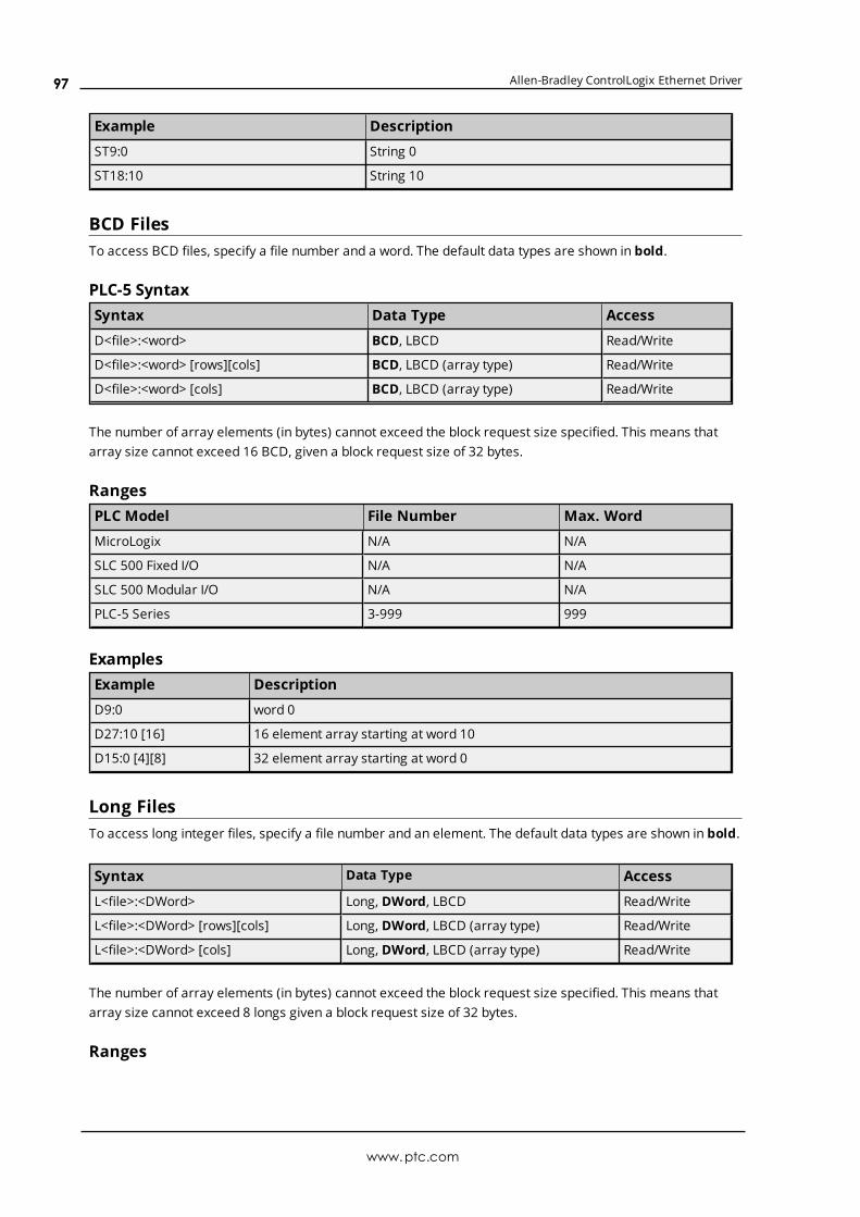
Allen-Bradley ControlLogix Ethernet Driver
Example Description
ST9:0 String 0
ST18:10 String 10
BCD FilesTo access BCD files, specify a file number and a word. The default data types are shown in bold.
PLC-5 SyntaxSyntax Data Type Access
D<file>:<word> BCD, LBCD Read/Write
D<file>:<word> [rows][cols] BCD, LBCD (array type) Read/Write
D<file>:<word> [cols] BCD, LBCD (array type) Read/Write
The number of array elements (in bytes) cannot exceed the block request size specified. This means thatarray size cannot exceed 16 BCD, given a block request size of 32 bytes.
RangesPLC Model File Number Max. Word
MicroLogix N/A N/A
SLC 500 Fixed I/O N/A N/A
SLC 500 Modular I/O N/A N/A
PLC-5 Series 3-999 999
ExamplesExample Description
D9:0 word 0
D27:10 [16] 16 element array starting at word 10
D15:0 [4][8] 32 element array starting at word 0
Long FilesTo access long integer files, specify a file number and an element. The default data types are shown in bold.
Syntax Data Type Access
L<file>:<DWord> Long, DWord, LBCD Read/Write
L<file>:<DWord> [rows][cols] Long, DWord, LBCD (array type) Read/Write
L<file>:<DWord> [cols] Long, DWord, LBCD (array type) Read/Write
The number of array elements (in bytes) cannot exceed the block request size specified. This means thatarray size cannot exceed 8 longs given a block request size of 32 bytes.
Ranges
www.ptc.com
97
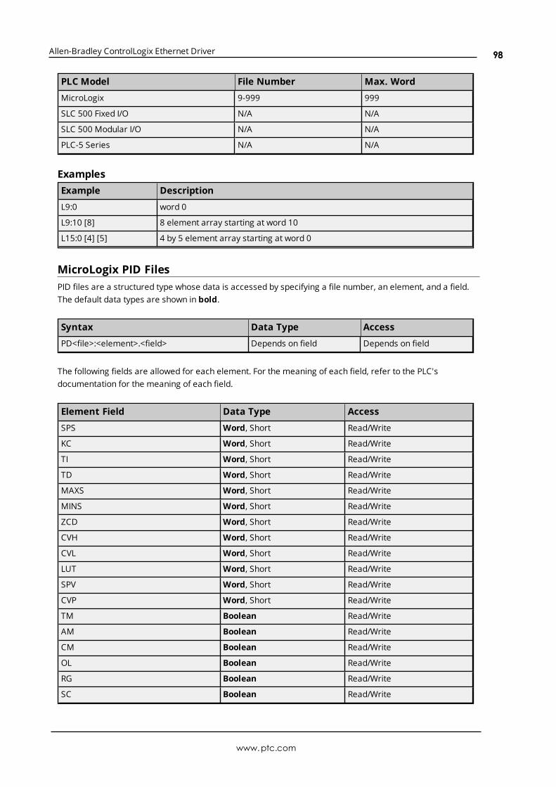
Allen-Bradley ControlLogix Ethernet Driver
PLC Model File Number Max. Word
MicroLogix 9-999 999
SLC 500 Fixed I/O N/A N/A
SLC 500 Modular I/O N/A N/A
PLC-5 Series N/A N/A
ExamplesExample Description
L9:0 word 0
L9:10 [8] 8 element array starting at word 10
L15:0 [4] [5] 4 by 5 element array starting at word 0
MicroLogix PID FilesPID files are a structured type whose data is accessed by specifying a file number, an element, and a field.The default data types are shown in bold.
Syntax Data Type Access
PD<file>:<element>.<field> Depends on field Depends on field
The following fields are allowed for each element. For the meaning of each field, refer to the PLC'sdocumentation for the meaning of each field.
Element Field Data Type Access
SPS Word, Short Read/Write
KC Word, Short Read/Write
TI Word, Short Read/Write
TD Word, Short Read/Write
MAXS Word, Short Read/Write
MINS Word, Short Read/Write
ZCD Word, Short Read/Write
CVH Word, Short Read/Write
CVL Word, Short Read/Write
LUT Word, Short Read/Write
SPV Word, Short Read/Write
CVP Word, Short Read/Write
TM Boolean Read/Write
AM Boolean Read/Write
CM Boolean Read/Write
OL Boolean Read/Write
RG Boolean Read/Write
SC Boolean Read/Write
www.ptc.com
98

Allen-Bradley ControlLogix Ethernet Driver
Element Field Data Type Access
TF Boolean Read/Write
DA Boolean Read/Write
DB Boolean Read/Write
UL Boolean Read/Write
LL Boolean Read/Write
SP Boolean Read/Write
PV Boolean Read/Write
DN Boolean Read/Write
EN Boolean Read/Write
RangesPLC Model File Number Max. Element
MicroLogix 3-255 255
All SLC N/A N/A
PLC-5 PID Files PID Files
ExamplesExample Description
PD14:0.KC Proportional gain of PD 0 file 14
PD18:6.EN PID enable bit of PD 6 file 18
PID FilesPID files are a structured type whose data is accessed by specifying a file number, an element, and a field.The default data types are shown in bold.
PLC-5 SyntaxSyntax Data Type Access
PD<file>:<element>.<field> Depends on field Depends on field
The following fields are allowed for each element. For the meaning of each field, refer to the PLC'sdocumentation.
Element Field Data Type Access
SP Real Read/Write
KP Real Read/Write
KI Real Read/Write
KD Real Read/Write
BIAS Real Read/Write
MAXS Real Read/Write
MINS Real Read/Write
www.ptc.com
99

Allen-Bradley ControlLogix Ethernet Driver
Element Field Data Type Access
DB Real Read/Write
SO Real Read/Write
MAXO Real Read/Write
MINO Real Read/Write
UPD Real Read/Write
PV Real Read/Write
ERR Real Read/Write
OUT Real Read/Write
PVH Real Read/Write
PVL Real Read/Write
DVP Real Read/Write
DVN Real Read/Write
PVDB Real Read/Write
DVDB Real Read/Write
MAXI Real Read/Write
MINI Real Read/Write
TIE Real Read/Write
FILE Word, Short Read/Write
ELEM Word, Short Read/Write
EN Boolean Read/Write
CT Boolean Read/Write
CL Boolean Read/Write
PVT Boolean Read/Write
DO Boolean Read/Write
SWM Boolean Read/Write
CA Boolean Read/Write
MO Boolean Read/Write
PE, Boolean Read/Write
INI Boolean Read/Write
SPOR Boolean Read/Write
OLL Boolean Read/Write
OLH Boolean Read/Write
EWD Boolean Read/Write
DVNA Boolean Read/Write
DVHA Boolean Read/Write
PVLA Boolean Read/Write
PVHA Boolean Read/Write
Ranges
www.ptc.com
100

Allen-Bradley ControlLogix Ethernet Driver
PLC Model File Number Max. Element
MicroLogix N/A N/A
SLC 500 Fixed I/O N/A N/A
SLC 500 Modular I/O N/A N/A
PLC-5 Series 3-999 999
ExamplesExample Description
PD14:0.SP Set point field of PD 0 file 14
PD18:6.EN Status enable bit of PD 6 file 18
MicroLogix Message FilesMessage files are a structured type whose data is accessed by specifying a file number, an element, and afield. The default data types are shown in bold.
Syntax Data Type Access
MG<file>:<element>.<field> Depends on field Depends on field
The following fields are allowed for each element. For the meaning of each field, refer to the PLC'sdocumentation.
Element Field Data Type Access
IA Word, Short Read/Write
RBL Word, Short Read/Write
LBN Word, Short Read/Write
RBN Word, Short Read/Write
CHN Word, Short Read/Write
NOD Word, Short Read/Write
MTO Word, Short Read/Write
NB Word, Short Read/Write
TFT Word, Short Read/Write
TFN Word, Short Read/Write
ELE Word, Short Read/Write
SEL Word, Short Read/Write
TO Boolean Read/Write
CO Boolean Read/Write
EN Boolean Read/Write
RN Boolean Read/Write
EW Boolean Read/Write
ER Boolean Read/Write
DN Boolean Read/Write
www.ptc.com
101

Allen-Bradley ControlLogix Ethernet Driver
Element Field Data Type Access
ST Boolean Read/Write
BK Boolean Read/Write
RangesPLC Model File Number Max. Element
MicroLogix 3-255 255
All SLC N/A N/A
PLC5 Message Files Message Files
ExamplesExample Description
MG14:0.TO Time out bit for MSG element 0 in data file 14
MG18:6.CO Continue bit for MSG element 6 in data file 18
Message FilesMessage files are a structured type whose data is accessed by specifying a file number, an element, and afield. The default data types are shown in bold.
PLC-5 SyntaxSyntax Data Type Access
MG<file>:<element>.<field> Depends on field Depends on field
The following fields are allowed for each element. For the meaning of each field, refer to the PLC'sdocumentation.
Element Field Data Type Access
ERR Short, Word Read/Write
RLEN Short, Word Read/Write
DLEN Short, Word Read/Write
EN Boolean Read/Write
ST Boolean Read/Write
DN Boolean Read/Write
ER Boolean Read/Write
CO Boolean Read/Write
EW Boolean Read/Write
NR Boolean Read/Write
TO Boolean Read/Write
Ranges
www.ptc.com
102

Allen-Bradley ControlLogix Ethernet Driver
PLC Model File Number Max. Element
MicroLogix N/A N/A
SLC 500 Fixed I/O N/A N/A
SLC 500 Modular I/O N/A N/A
PLC-5 Series 3-999 999
ExamplesExample Description
MG14:0.RLEN Requested length field of MG 0 file 14
MG18:6.CO Continue bit of MG 6 file 18
Block Transfer FilesBlock transfer files are a structured type whose data is accessed by specifying a file number, an element,and a field. The default data types are shown in bold.
PLC-5 SyntaxSyntax Data Type Access
BT<file>:<element>.<field> Depends on field Depends on field
The following fields are allowed for each element. For more information on the meaning of each field, referto the PLC's documentation.
Element Field Data Type Access
RLEN Word, Short Read/Write
DLEN Word, Short Read/Write
FILE Word, Short Read/Write
ELEM Word, Short Read/Write
RW Boolean Read/Write
ST Boolean Read/Write
DN Boolean Read/Write
ER Boolean Read/Write
CO Boolean Read/Write
EW Boolean Read/Write
NR Boolean Read/Write
TO Boolean Read/Write
RangesPLC Model File Number Max. Element
MicroLogix N/A N/A
SLC 500 Fixed I/O N/A N/A
SLC 500 Modular I/O N/A N/A
PLC-5 Series 3-999 1999
www.ptc.com
103
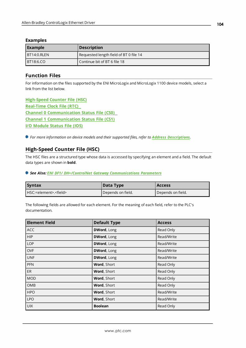
Allen-Bradley ControlLogix Ethernet Driver
ExamplesExample Description
BT14:0.RLEN Requested length field of BT 0 file 14
BT18:6.CO Continue bit of BT 6 file 18
Function FilesFor information on the files supported by the ENI MicroLogix and MicroLogix 1100 device models, select alink from the list below.
High-Speed Counter File (HSC)Real-Time Clock File (RTC)Channel 0 Communication Status File (CS0)Channel 1 Communication Status File (CS1)I/O Module Status File (IOS)
For more information on device models and their supported files, refer to Address Descriptions.
High-Speed Counter File (HSC)The HSC files are a structured type whose data is accessed by specifying an element and a field. The defaultdata types are shown in bold.
See Also: ENI DF1/ DH+/ControlNet Gateway Communications Parameters
Syntax Data Type Access
HSC:<element>.<field> Depends on field. Depends on field.
The following fields are allowed for each element. For the meaning of each field, refer to the PLC'sdocumentation.
Element Field Default Type Access
ACC DWord, Long Read Only
HIP DWord, Long Read/Write
LOP DWord, Long Read/Write
OVF DWord, Long Read/Write
UNF DWord, Long Read/Write
PFN Word, Short Read Only
ER Word, Short Read Only
MOD Word, Short Read Only
OMB Word, Short Read Only
HPO Word, Short Read/Write
LPO Word, Short Read/Write
UIX Boolean Read Only
www.ptc.com
104

Allen-Bradley ControlLogix Ethernet Driver
Element Field Default Type Access
UIP Boolean Read Only
AS Boolean Read Only
ED Boolean Read Only
SP Boolean Read Only
LPR Boolean Read Only
HPR Boolean Read Only
DIR Boolean Read Only
CD Boolean Read Only
CU Boolean Read Only
UIE Boolean Read/Write
UIL Boolean Read/Write
FE Boolean Read/Write
CE Boolean Read/Write
LPM Boolean Read/Write
HPM Boolean Read/Write
UFM Boolean Read/Write
OFM Boolean Read/Write
LPI Boolean Read/Write
HPI Boolean Read/Write
UFI Boolean Read/Write
OFI Boolean Read/Write
UF Boolean Read/Write
OF Boolean Read/Write
MD Boolean Read/Write
RangesPLC Model File Number Max. Element
MicroLogix N/A 254
All SLC N/A N/A
PLC5 N/A N/A
ExamplesExample Description
HSC:0.OMB Output mask setting for high-speed counter 0.
HSC:1.ED Error detected indicator for high-speed counter 1.
Real-Time Clock File (RTC)The RTC files are a structured type whose data is accessed by specifying an element and a field. The defaultdata types are shown in bold.
www.ptc.com
105

Allen-Bradley ControlLogix Ethernet Driver
See Also: ENI DF1/ DH+/ControlNet Gateway Communications Parameters
Syntax Data Type Access
RTC:<element>.<field> Depends on field Depends on field
The following fields are allowed for each element. For the meaning of each field, refer to the PLC'sdocumentation.
Element Field Data Type Access
YR Word, Short Read/Write
MON Word, Short Read/Write
DAY Word, Short Read/Write
HR Word, Short Read/Write
MIN Word, Short Read/Write
SEC Word, Short Read/Write
DOW Word, Short Read/Write
DS Boolean Read Only
BL Boolean Read Only
_SET (for block writes) Boolean Read/Write
RangesPLC Model File Number Max. Element
MicroLogix N/A 254
All SLC N/A N/A
PLC5 N/A N/A
ExamplesExample Description
RTC:0.YR Year setting for real-time clock 0.
RTC:0.BL Battery low indicator for real-time clock 0.
Channel 0 Communication Status File (CS0)To access the communication status file for channel 0, specify a word (and optionally a bit in the word). Thedefault data types are shown in bold.
See Also: ENI DF1/ DH+/ControlNet Gateway Communications Parameters
Syntax Data Type Access
CS0:<word> Short, Word, BCD, DWord, Long, LBCD Depends on <word> and <bit>
CS0:<word>/<bit> Boolean Depends on <word> and <bit>
CS0/bit Boolean Depends on <word> and <bit>
Ranges
www.ptc.com
106

Allen-Bradley ControlLogix Ethernet Driver
PLC Model File Number Max. Element
MicroLogix N/A 254
All SLC N/A N/A
PLC5 N/A N/A
ExamplesExample Description
CS0:0 Word 0.
CS0:4/2 Bit 2 word 4 = MCP.
For more information on CS0 words/bit meanings, refer to the Rockwell documentation.
Channel 1 Communication Status File (CS1)To access the communication status file for channel 1, specify a word (and optionally a bit in the word). Thedefault data types are shown in bold.
See Also: ENI DF1/ DH+/ControlNet Gateway Communications Parameters
Syntax Data Type Access
CS1:<word> Short, Word, BCD, DWord, Long, LBCD Depends on <word> and <bit>
CS1:<word>/<bit> Boolean Depends on <word> and <bit>
CS1/bit Boolean Depends on <word> and <bit>
RangesPLC Model File Number Max. Element
MicroLogix N/A 254
All SLC N/A N/A
PLC5 N/A N/A
ExamplesExample Description
CS1:0 Word 0.
CS1:4/2 Bit 2 word 4 = MCP.
For more information on CS1 words/bit meanings, refer to the Rockwell documentation.
I/O Module Status File (IOS)To access an I/O module status file, specify a word and optionally a bit. The default data types are shown inbold.
See Also: ENI DF1/ DH+/ControlNet Gateway Communications Parameters
www.ptc.com
107

Allen-Bradley ControlLogix Ethernet Driver
Syntax Data Type Access
IOS:<word> Short, Word, BCD, DWord, Long, LBCD Depends on <word> and <bit>
IOS:<word>/<bit> Boolean Depends on <word> and <bit>
IOS/bit Boolean Depends on <word> and <bit>
RangesPLC Model File Number Max. Element
MicroLogix N/A 254
All SLC N/A N/A
PLC5 N/A N/A
ExamplesExample Description
IOS:0 Word 0.
IOS:4/2 Bit 2 word 4.
Note: For a listing of 1769 expansion I/O status codes, refer to the instruction manual.
www.ptc.com
108

Allen-Bradley ControlLogix Ethernet Driver
Automatic Tag Database GenerationThe Allen-Bradley ControlLogix Ethernet Driver can be configured to automatically generate a list of servertags within the server that correspond to device-specific data. The automatically generated tags are basedon the Logix tags defined in the Logix device, and can be browsed from the OPC client. Logix tags can beatomic or structured. Structure and array tags can quickly increase the number of tags imported (andtherefore the number of tags available in the server).
Note: ENI/DH+, ControlNet Gateway, and MicroLogix 1100 models do not support automatic tag databasegeneration: only ENI ControlLogix, CompactLogix, and FlexLogix models do.
Atomic Tag -> one-to-one -> Server TagStructure Tag -> one-to-many -> Server TagsArray Tag -> one-to-many> -> Server Tags
For more information on the Database Creation settings, refer to the server help file.
Note: Controller tags observed in the RSLogix5000 programming environment must have the "ExternalAccess" property configured to "Read Only" or "Read/Write" for the tags to be read. Automatically generatedtags may set External Access to "None" by default. To read controller tags, reconfigure External Access asneeded in the Add-On Instruction Parameters of RSLogix. Consult the manufacturer documentation.
Tag HierarchyThe server tags created by automatic tag generation can follow one of two hierarchies: Expanded orCondensed. To use this functionality, enable Allow Sub Groups in device properties.
Expanded ModeWhen Expanded, the server tags created by automatic tag generation follow a group / tag hierarchyconsistent with the tag hierarchy in RSLogix 5000. Groups are created for every segment preceding theperiod as when Condensed, but are also created in logical groupings. Groups created include the following:
l Global (controller) scope
l Program scope
l Structures and substructures
l Arrays
Note: Groups are not created for .bit addresses.
The root-level groups (or subgroup levels of the group specified in Parent Group) are "Prgm_<programname>" and "Global". Each program in the controller has its own "Prgm_<program name>" group. Thedriver recognizes this as the first group level.
Basic Global Tags (or non-structure, non-array tags) are placed under the Global group; basic Program tagsare placed under their respective program group. Each structure and array tag is provided in its ownsubgroup of the parent group. By organizing the data in this fashion, the server's tag view mimicsRSLogix5000.
The name of the structure / array subgroup also provides a description of the structure / array. For instance,an array tag1[1,6] defined in the controller would have a subgroup name "tag1_x_y"; x signifies dimension 1exists, and y signifies dimension 2 exists. The tags within an array subgroup are all the elements of that
www.ptc.com
109

Allen-Bradley ControlLogix Ethernet Driver
array (unless explicitly limited). The tags within a structure subgroup are the structure membersthemselves. If a structure contains an array, an array subgroup of the structure group is created as well.
With a complex project, the tag hierarchy can require a number of group levels. The maximum number ofgroup levels created by automatic tag generation is seven. This does not include the group specified in "Addgenerated tags to the following group". When more than seven levels are required, the tags are placed inthe seventh group (causing the hierarchy to plateau).
Array TagsA group is created for each array that contains the array's elements. Group names have the notation: <arrayname>_x_y_z where:
x_y_z = 3 dimensional arrayx_y = 2 dimensional arrayx = 1 dimensional array
Array tags have the notation: <tag element>_XXXXX_YYYYY_ZZZZZ. For example, element tag1[12,2,987] wouldhave the tag name "tag1_12_2_987".
Simple Example
Complex ExampleA Logix tag is defined with the address "Local:1:O.Slot[9].Data". This would be represented in the groups"Global" - "Local_1_O" - "Slot_x" - "Slot_09". Within the last group would be the tag "Data".
The static reference to "Data" would be "Channel1.Device1.Global.Local_1_O.Slot_x.Slot_09.Data". Thedynamic reference to "Data" would be "Channel1.Device1.Local:1:O.Slot[9].Data".
www.ptc.com
110

Allen-Bradley ControlLogix Ethernet Driver
Condensed ModeIn Condensed Mode, the server tags created by automatic tag generation follow a group/tag hierarchyconsistent with the tag's address. Groups are created for every segment preceding the period. Groupscreated include the following:
l Program scope
l Structures and substructures
Note: Groups are not created for arrays or .bit addresses.
With a complex project, it is easy to see how the tag hierarchy can require a number of group levels. Themaximum number of group levels created by automatic tag generation is seven. This does not include thegroup specified in "Add generated tags to the following group". When more than seven levels are required,the tags are placed in the seventh group (causing the hierarchy to plateau).
Note: Tag or structure member names leading off with an underscore is converted to "U_". This isrequired because the server does not support leading underscores. For more information, refer toController-to-Server Name Conversion.
Simple Example
Complex ExampleLogix tag is defined with address "Local:1:O.Slot[9].Data". This would be represented in the groups"Local:1:O" -> "Slot[9]". Within the last group would be the tag "Data".
The static reference to "Data" would be "Channel1.Device1.Local:1:O.Slot[9].Data". The dynamic referencewould be "Channel1.Device1.Local:1:O.Slot[9].Data".
www.ptc.com
111

Allen-Bradley ControlLogix Ethernet Driver
Note: I/O module tags cannot be directly imported in Offline mode. Since aliases can be imported, it isrecommended that they be created for I/O module tags of interest in RSLogix5000.
Controller-to-Server Name ConversionsLeading UnderscoresLeading underscores "_" in tag or program names are replaced with "U_". This is required because theserver does not accept tag or group names beginning with an underscore.
Long Names (OPC Server Version 4.64 and below)Under older OPC server versions, the Allen-Bradley ControlLogix Ethernet Driver was limited to 31characters in group and tag names. Therefore, if a controller program or tag name exceeded 31 characters,it had to be clipped. OPC server Version 4.70 and above has a 256 character limit, so the rules do not apply.Names are clipped as follows:
Non-Array
1. Determine a 5-digit unique ID for this tag.
2. Given a tag name: ThisIsALongTagNameAndProbablyExceeds31
3. Clip tag at 31: ThisIsALongTagNameAndProbablyEx
4. Room is made for the unique ID: ThisIsALongTagNameAndProba#####
5. Insert this ID: ThisIsALongTagNameAndProba00000
Array
1. Determine a 5-digit unique ID for this array.
2. Given an array tag name: ThisIsALongTagNameAndProbablyExceeds31_23_45_8
3. Clip tag at 31 while holding on to the element values: ThisIsALongTagNameAndPr_23_45_8
4. Room is made for the unique ID: ThisIsALongTagName#####_23_45_8
5. Insert this ID: ThisIsALongTagName00001_23_45_8
Long program names are clipped in the same manner as long non-array tag names. For every tag orprogram name that is clipped, the unique ID is incremented. Array tag names (elements) of a clipped arrayname have the same unique ID. This provides for 100000 unique tag/program names.
Note: If Limit Name Length is enabled, the rules apply even if the 256-character names are supported.For more information, refer to Logix Database Settings.
Preparing for Automatic Tag Database GenerationFor information on using Automatic Tag Database Generation, follow the instructions below.
OnlineIt is recommended that all communications to the Logix CPU of interest cease during the database creationprocess.
In RSLogix5000Set the project OFFLINE.
www.ptc.com
112

Allen-Bradley ControlLogix Ethernet Driver
In the server
1. Open the device properties of the device for which tags will be generated.
2. Select Logix Database Settings and select Create from Device for Database Import Method.
3. In Logix Database Options, make any desired changes and click OK.
4. In Logix Database Filtering, make any desired changes and click OK.
5. Select Tag Generation and, under Create, click the blue link to Create tags.
Note: In Logix Options, set Protocol Mode to Symbolic and Default Data Type to Default so that thetags are imported with the data types used in the controller.
OfflineThe Allen-Bradley ControlLogix Ethernet Driver uses a file generated from RSLogix5000 called an L5K/L5Ximport/export file to generate the tag database.
In RSLogix5000
1. Open the project containing the tags that to be ported over to the OPC server.
2. Click File | Save As.
3. Select L5K/L5X Import/Export File and then specify a name. RSLogix will export the project'scontents into this L5K/L5X file.
In the OPC Server
1. Open the device properties of the device for which tags will be generated.
2. Select Logix Database Settings and select Create from Import File for Database ImportMethod.
3. Enter or browse for the location of the file previously created.
4. In Logix Database Options, make any desired changes and click OK.
5. In Logix Database Filtering, make any desired changes and click OK.
6. Select Tag Generation and, under Create, click the blue link to Create tags.
Note: Imported pre-defined tag types are based on the latest version supported by the driver. For moreinformation, refer to Firmware Versions.
www.ptc.com
113

Allen-Bradley ControlLogix Ethernet Driver
Error CodesThe following sections define error codes that may be encountered in the server's Event Log. For moreinformation on a specific error code type, select a link from the list below.
Encapsulation Error CodesCIP Error Codes
Encapsulation Error CodesThe following error codes are in hexadecimal.
Error Code Description
0001 Command not handled.
0002 Memory not available for command.
0003 Poorly formed or incomplete data.
0064 Invalid session ID.
0065 Invalid length in header.
0069 Requested protocol version not supported.
0070 Invalid target ID.
CIP Error CodesThe following error codes are in hexadecimal.
Error Code Log Code Description
0001 0x01 Connection Failure.*
0002 0x02 Insufficient resources.
0003 0x03 Value invalid.
0004 0x04 IOI could not be deciphered or tag does not exist.
0005 0x05 Unknown destination.
0006 0x06 Data requested would not fit in response packet.
0007 0x07 Loss of connection.
0008 0x08 Unsupported service.
0009 0x09 Error in data segment or invalid attribute value.
000A 0x0A Attribute list error.
000B 0x0B State already exists.
000C 0x0C Object model conflict.
000D 0x0D Object already exists.
000E 0x0E Attribute not settable.
000F 0x0F Permission denied.
0010 0x10 Device state conflict.
0011 0x11 Reply does not fit.
0012 0x12 Fragment primitive.
0013 0x13 Insufficient command data / parameters specified to execute service.
www.ptc.com
114

Allen-Bradley ControlLogix Ethernet Driver
Error Code Log Code Description
0014 0x14 Attribute not supported.
0015 0x15 Too much data specified.
001A 0x1A Bridge request too large.
001B 0x1B Bridge response too large.
001C 0x1C Attribute list shortage.
001D 0x1D Invalid attribute list.
001E 0x1E Embedded service error.
001F 0x1F Failure during connection.**
0022 0x22 Invalid reply received.
0025 0x25 Key segment error.
0026 0x26 Number of IOI words specified does not match IOI word count.
0027 0x27 Unexpected attribute in list.
*See Also: 0x0001 Extended Error Codes**See Also: 0x001F Extended Error Codes
Logix5000-Specific (1756-L1) Error CodesThe following error codes are in hexadecimal.
Error Code Description
00FF General Error.*
*See Also: 0x00FF Extended Error Codes
Note: For unlisted error codes, refer to the Rockwell documentation.
0x0001 Extended Error CodesThe following error codes are in hexadecimal.
Error Code Description
0100 Connection in use.
0103 Transport not supported.
0106 Ownership conflict.
0107 Connection not found.
0108 Invalid connection type.
0109 Invalid connection size.
0110 Module not configured.
0111 EPR not supported.
0114 Wrong module.
0115 Wrong device type.
0116 Wrong revision.
www.ptc.com
115
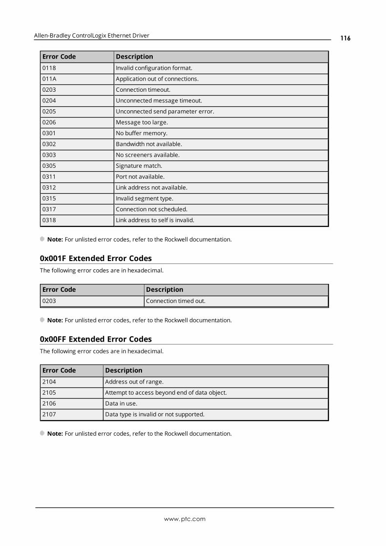
Allen-Bradley ControlLogix Ethernet Driver
Error Code Description
0118 Invalid configuration format.
011A Application out of connections.
0203 Connection timeout.
0204 Unconnected message timeout.
0205 Unconnected send parameter error.
0206 Message too large.
0301 No buffer memory.
0302 Bandwidth not available.
0303 No screeners available.
0305 Signature match.
0311 Port not available.
0312 Link address not available.
0315 Invalid segment type.
0317 Connection not scheduled.
0318 Link address to self is invalid.
Note: For unlisted error codes, refer to the Rockwell documentation.
0x001F Extended Error CodesThe following error codes are in hexadecimal.
Error Code Description
0203 Connection timed out.
Note: For unlisted error codes, refer to the Rockwell documentation.
0x00FF Extended Error CodesThe following error codes are in hexadecimal.
Error Code Description
2104 Address out of range.
2105 Attempt to access beyond end of data object.
2106 Data in use.
2107 Data type is invalid or not supported.
Note: For unlisted error codes, refer to the Rockwell documentation.
www.ptc.com
116

Allen-Bradley ControlLogix Ethernet Driver
Event Log MessagesThe following information concerns messages posted to the Event Log pane in the main user interface.Consult the server help on filtering and sorting the Event Log detail view. Server help contains manycommon messages, so should also be searched. Generally, the type of message (informational, warning)and troubleshooting information is provided whenever possible.
The following errors occurred uploading controller project from device.Resorting to Symbolic Protocol.Error Type:Error
Invalid or corrupt controller project detected while synchronizing.Synchronization will be retried shortly.Error Type:Error
Possible Cause:An invalid or corrupt controller project was detected during synchronization.
Possible Solution:No action is required. The driver attempts synchronization again after 30 seconds.
Note:Project synchronization is required for the Logical Addressing Modes.
Project download detected while synchronizing. Synchronization will beretried shortly.Error Type:Error
Possible Cause:A project download was attempted while the device was synchronizing with the controller project.
Possible Solution:No action is required. The driver attempts synchronization again after 30 seconds.
Note:Project synchronization is required for the Logical Addressing Modes.
Database error. Data type for reference tag unknown. Setting alias tagdata type to default. | Reference tag = '<tag>', Alias tag = '<tag>', Defaultdata type = '<type>'.Error Type:
www.ptc.com
117

Allen-Bradley ControlLogix Ethernet Driver
Error
Possible Cause:The data type of the "Alias For" tag referenced in the alias tag declaration could not found in the tag importfile. This data type is necessary to generate the alias tag correctly.
Possible Solution:The Alias tag assumes the data type specified as the Default Type.
Note:In RSLogix5000, there is an "Alias For" column in the tag view under the Edit Tags tab where the reference tothe tag, structure tag member, or bit that the alias tag will represent is entered.
See Also:Logix Options
Database error. Member data type not found in tag import file. Settingdata type to default. | Member data type = '<type>', UDT = '<type>',Default data type '<type>'.Error Type:Error
Possible Cause:The definition of the data type for a member in the user-defined type could not be found in the tag importfile. The member takes the default type specified in the Device Properties.
Possible Solution:Verify or correct the definition of the user-defined data types for the specified tags and retry the import.
See Also:Logix Options
Database error. Data type not found in tag import file. Tag not added. |Data type = '<type>', Tag name = '<tag>'.Error Type:Error
Possible Cause:The definition of the data type for the specified tag could not be found in the tag import file. Tag is not addedto the database.
Possible Solution:Verify or correct the definition of the data types for the specified tags and retry the import.
Database error. Error occurred processing alias tag. Tag not added. | Aliastag = '<tag>'.Error Type:
www.ptc.com
118

Allen-Bradley ControlLogix Ethernet Driver
Error
Possible Cause:An internal error occurred processing alias tag. Alias tag could not be generated.
Possible Solution:Verify or correct the definition of the data types for the specified tags and retry the import.
Database error. Encapsulation error occurred during register sessionrequest. | Encapsulation error = <code>.Error Type:Error
Possible Cause:The device returned an error within the Encapsulation portion of the Ethernet/IP packet during a request. Allreads and writes within the request failed.
Possible Solution:The driver attempts to recover from such an error. If the problem persists, contact Technical Support. Thisexcludes error 0x02, which is device-related, not driver-related.
See Also:Encapsulation Error Codes
Database error. Framing error occurred during register session request.Error Type:Error
Database error. Encapsulation error occurred during fwd. open request. |Encapsulation error = <code>.Error Type:Error
Database error. Framing error occurred during forward open request.Error Type:Error
Database error. Error occurred during forward open request. | CIP error =<code>, Extended error = <code>.Error Type:Error
Database error. Encapsulation error occurred while uploading projectinformation. | Encapsulation error = <code>.Error Type:
www.ptc.com
119

Allen-Bradley ControlLogix Ethernet Driver
Error
Possible Cause:The device returned an error within the encapsulation portion of the Ethernet/IP packet while uploading thecontroller project.
Possible Solution:The solution depends on the error code returned. If the problem persists, contact Technical Support.
Note:A project upload is required for the Logical Addressing Modes.
See Also:Encapsulation Error Codes
Database error. Error occurred while uploading project information. | CIPerror = <code>, Extended error = <code>.Error Type:Error
Possible Cause:The device returned an error within the CIP portion of the Ethernet/IP packet while uploading the controllerproject.
Possible Solution:The solution depends on the error code returned. If the problem persists, contact Technical Support.
Note:A project upload is required for the Logical Addressing Modes.
See Also:CIP Error Codes
Database error. Framing error occurred while uploading projectinformation.Error Type:Error
Possible Cause:
1. The packets are misaligned (due to connection/disconnection between the PC and device).
2. There is bad cabling connecting the device that is causing noise.
Possible Solution:
1. Place the device on a less noisy network.
2. Increase the request timeout and/or attempts.
www.ptc.com
120
Allen-Bradley ControlLogix Ethernet Driver
3. Restart the server and try again.
Note:A project upload is required for the Logical Addressing Modes.
Database error. Internal error occurred.Error Type:Error
Database error. Encapsulation error occurred while uploading programinformation. | Program name = '<name>', Encapsulation error = <code>.Error Type:Error
Possible Cause:The device returned an error within the encapsulation portion of the Ethernet/IP packet while uploading thecontroller project.
Possible Solution:The solution depends on the error code returned. If the problem persists, contact Technical Support.
Note:A project upload is required for the Logical Addressing Modes.
See Also:Encapsulation Error Codes
Database error. Error occurred while uploading program information. |Program name = '<name>', CIP error = <code>, Extended error = <code>.Error Type:Error
Possible Cause:The device returned an error within the CIP portion of the Ethernet/IP packet while uploading the controllerproject.
Possible Solution:The solution depends on the error code that is returned. If the problem persists, contact Technical Support.
Note:A project upload is required for the Logical Addressing Modes.
See Also:CIP Error Codes
www.ptc.com
121

Allen-Bradley ControlLogix Ethernet Driver
Database error. Framing error occurred while uploading programinformation. | Program name = '<name>'.Error Type:Error
Possible Cause:
1. The packets are misaligned (due to connection/disconnection between the PC and device).
2. There is bad cabling connecting the device that is causing noise.
Possible Solution:
1. Place the device on a less noisy network.
2. Increase the request timeout and/or attempts.
3. Restart the server and try again.
Note:A project upload is required for the Logical Addressing Modes.
Database error. Unable to resolve CIP data type for tag. Setting to defaulttype. | CIP data type = <type>, Tag name = '<tag>', Default data type ='<type>'.Error Type:Error
Possible Cause:
1. The CIP data type in the import file is unknown.
2. The import file may contain an error.
Possible Solution:Resolve any errors in RSLogix, then retry the tag export process to produce a new tag import file.
See Also:Preparing for Automatic Tag Database Generation
Encapsulation error occurred while uploading project information. |Encapsulation error = <code>.Error Type:Error
Possible Cause:The device returned an error within the encapsulation portion of the Ethernet/IP packet while uploading thecontroller project.
www.ptc.com
122
Allen-Bradley ControlLogix Ethernet Driver
Possible Solution:The solution depends on the error code returned. If the problem persists, contact Technical Support.
Note:A project upload is required for the Logical Addressing Modes.
See Also:Encapsulation Error Codes
Error occurred while uploading project information. | CIP error = <code>,Extended error = <code>.Error Type:Error
Possible Cause:The device returned an error within the CIP portion of the Ethernet/IP packet while uploading the controllerproject.
Possible Solution:The solution depends on the error code that is returned. If the problem persists, contact Technical Support.
Note:A project upload is required for the Logical Addressing Modes.
See Also:CIP Error Codes
Framing error occurred while uploading project information.Error Type:Error
Possible Cause:
1. The packets are misaligned (due to connection/disconnection between the PC and device).
2. There is bad cabling connecting the device that is causing noise.
Possible Solution:
1. Place the device on a less noisy network.
2. Increase the request timeout and/or attempts.
3. Restart the server and try again.
Note:A project upload is required for the Logical Addressing Modes.
www.ptc.com
123

Allen-Bradley ControlLogix Ethernet Driver
Encapsulation error occurred while uploading program information. |Program name = '<name>', Encapsulation error = <code>.Error Type:Error
Error occurred while uploading program information. | Program name ='<name>', CIP error = <code>, Extended error = <code>.Error Type:Error
Framing error occurred while uploading program information. | Programname = '<name>'.Error Type:Error
Encapsulation error occurred while uploading controller programinformation. Encapsulation error = <code>.Error Type:Error
Error occurred while uploading controller program information. CIP error= <code>, Extended error = <code>.Error Type:Error
Framing error occurred while uploading controller program information.Error Type:Error
CIP connection timed out while uploading project information.Error Type:Error
Possible Cause:The Inactivity Watchdog is set too low to allow the project to load.
Possible Solution:Increase the Inactivity Watchdog value and try again.
Database error. CIP connection timed out while uploading projectinformation.Error Type:Error
www.ptc.com
124

Allen-Bradley ControlLogix Ethernet Driver
Possible Cause:The Inactivity Watchdog is set too low to allow the project to load.
Possible Solution:Increase the Inactivity Watchdog value and try again.
Database error. No more connections available for fwd. open request.Error Type:Error
Error opening file for tag database import. | OS error = '<code>'.Error Type:Error
Controller not supported. | Vendor ID = <ID>, Product type = <type>,Product code = <code>, Product name = '<name>'.Error Type:Warning
Frame received from device contains errors.Error Type:Warning
Possible Cause:
1. The packets are misaligned due to connection and/or disconnection between the PC and device.
2. There is bad cabling connecting the device that is causing noise.
Possible Solution:
1. Place the device on less noisy network.
2. Increase the request timeout and/or attempts.
Write request failed due to a framing error. | Tag address = '<address>'.Error Type:Warning
Possible Cause:
1. There is an incorrect request service code.
2. The driver received more or fewer bytes than expected.
3. If this error occurs frequently, there may be an issue with the cabling or device.
www.ptc.com
125

Allen-Bradley ControlLogix Ethernet Driver
Possible Solution:
1. Increase the retry attempts to allow the driver to recover from this error.
2. Verify the cabling and device are functioning properly.
Read request for tag failed due to a framing error. | Tag address ='<address>'.Error Type:Warning
Possible Cause:
1. There is an incorrect request service code.
2. The driver received more or fewer bytes than expected.
3. If this error occurs frequently, there may be an issue with the cabling or device.
Possible Solution:
1. Increase the retry attempts to allow the driver to recover from this error.
2. Verify the cabling and device are functioning properly.
Block read request failed due to a framing error. | Block size = <number>(elements), Block start address = '<address>'.Error Type:Warning
Possible Cause:
1. The Ethernet connection between the device and the host PC is broken.
2. The communication parameters for the Ethernet connection are incorrect.
3. The named device may have been assigned an incorrect IP address.
Possible Solution:
1. Verify the cabling between the PC and the device.
2. Verify that the correct port has been specified for the named device.
3. Verify that the IP address given to the named device matches that of the actual device.
Block read request failed due to a framing error. | Block size = <number>(bytes), Block name = '<name>'.Error Type:Warning
www.ptc.com
126

Allen-Bradley ControlLogix Ethernet Driver
Possible Cause:
1. There is an incorrect request service code.
2. The driver received more or fewer bytes than expected.
3. If this error occurs frequently, there may be an issue with the cabling or device.
Possible Solution:
1. Increase the retry attempts to allow the driver to recover from this error.
2. Verify the cabling and device are functioning properly.
Unable to write to tag. | Tag address = '<address>', CIP error = <code>,Extended error = <code>.Error Type:Warning
Possible Cause:The device returned an error within the CIP portion of the Ethernet/IP packet during a write request for thespecified tag.
Possible Solution:The solution depends on the error codes returned.
See Also:CIP Error Codes
Unable to read tag. | Tag address = '<address>', CIP error = <code>,Extended error = <code>.Error Type:Warning
Possible Cause:The device returned an error within the CIP portion of the Ethernet/IP packet during a read request for thespecified tag.
Possible Solution:The solution depends on the error codes returned.
See Also:CIP Error Codes
Unable to read block. | Block size = <number> (elements), Block startaddress = '<address>', CIP error = <code>, Extended error = <code>.Error Type:
www.ptc.com
127
Allen-Bradley ControlLogix Ethernet Driver
Warning
Unable to read block. | Block size = <number> (bytes), Tag name = '<tag>',CIP error = <code>, Extended error = <code>.Error Type:Warning
Unable to write to tag. Controller tag data type unknown. | Tag address ='<address>', Data type = <type>.Error Type:Warning
Possible Cause:A write request for the specified tag failed because the controller tag data type is not supported.
Possible Solution:Contact Technical Support so that support may be added for this type.
See Also:Addressing Atomic Data Types
Unable to read tag. Controller tag data type unknown. Tag deactivated. |Tag address = '<address>', Data type = <type>.Error Type:Warning
Possible Cause:A read request for the specified tag failed because the controller tag data type is not supported.
Possible Solution:Contact Technical Support so that support may be added for this type.
See Also:Addressing Atomic Data Types
Unable to read block. Controller tag data type unknown. Blockdeactivated. | Block size = <number> (elements), Block start address ='<address>', Data type = <type>.Error Type:Warning
Possible Cause:A read request for the specified block failed because a controller tag data type within the block is notsupported.
Possible Solution:
www.ptc.com
128
Allen-Bradley ControlLogix Ethernet Driver
Contact Technical Support so that support may be added for this type.
See Also:Addressing Atomic Data Types
Unable to write to tag. Data type not supported. | Tag address ='<address>', Data type = '<type>'.Error Type:Warning
Possible Cause:A write request for the specified tag failed because the client tag data type is not supported.
Possible Solution:Change the tag data type to one that is supported.
See Also:Addressing Atomic Data Types
Unable to read tag. Data type not supported. Tag deactivated. | Tagaddress = '<address>', Data type = '<type>'.Error Type:Warning
Possible Cause:A read request for the specified tag failed because the controller tag data type is not supported.
Possible Solution:Contact Technical Support so that support may be added for this type.
See Also:Addressing Atomic Data Types
Unable to read block. Data type not supported. Block deactivated. | Blocksize = <number> (elements), Block start address = '<address>', Data type ='<type>'.Error Type:Warning
Possible Cause:A read request for the specified block failed because a controller tag data type within the block is notsupported.
Possible Solution:Contact Technical Support so that support may be added for this type.
www.ptc.com
129

Allen-Bradley ControlLogix Ethernet Driver
See Also:Addressing Atomic Data Types
Unable to write to tag. Data type is illegal for this tag. | Tag address ='<address>', Data type = '<type>'.Error Type:Warning
Possible Cause:A write request for the specified tag failed because the client tag data type is illegal for the given controllertag.
Possible Solution:Change the tag data type to one that is supported. For example, data type Short is illegal for a BOOL arraycontroller tag. Changing the data type to Boolean would remedy this problem.
See Also:Addressing Atomic Data Types
Unable to read tag. Data type is illegal for this tag. Tag deactivated | Tagaddress = '<address>', Data type = '<type>'.Error Type:Warning
Possible Cause:A read request for the specified tag failed because the client tag data type is illegal for the given controllertag.
Possible Solution:Change the tag data type to one that is supported. For example, data type Short is illegal for a BOOL arrayController tag. Changing the data type to Boolean can remedy the problem.
See Also:Addressing Atomic Data Types
Unable to read block. Data type is illegal for this block. Block deactivated.| Block size = <number> (elements), Block start address = '<address>',Data type = '<type>'.Error Type:Warning
Possible Cause:A read request for block failed because the client tag data type is illegal for the given controller tag.
Possible Solution:
www.ptc.com
130

Allen-Bradley ControlLogix Ethernet Driver
Change the data type for tags within this block to supported types. For example, data type Short is illegal fora BOOL array Controller tag. Changing the data type to Boolean would remedy this problem.
See Also:Addressing Atomic Data Types
Unable to write to tag. Tag does not support multi-element arrays. | Tagaddress = '<address>'.Error Type:Warning
Possible Cause:A read request for the specified tag failed because the driver does not support multi-element array accessto the given controller tag.
Possible Solution:Change the tag data type or address to one that is supported.
See Also:Addressing Atomic Data Types
Unable to read tag. Tag does not support multi-element arrays. Tagdeactivated. | Tag address = '<address>'.Error Type:Warning
Possible Cause:A read request for the specified tag failed because the driver does not support multi-element array accessto the given controller tag.
Possible Solution:Change the tag data type or address to one that is supported. In response to this error, the tag isdeactivated and not processed again.
See Also:Addressing Atomic Data Types
Unable to read block. Block does not support multi-element arrays. Blockdeactivated. | Block size = <number> (elements), Block start address ='<address>'.Error Type:Warning
Possible Cause:A read request for tags in this block failed because the driver does not support multi-element array accessto the given controller tag.
www.ptc.com
131
Allen-Bradley ControlLogix Ethernet Driver
Possible Solution:Change the data type or address for tags within this block to supported types. In response to this error,<count> elements of the block are deactivated and not processed again.
See Also:Addressing Atomic Data Types
Unable to write to tag. Native tag size mismatch. | Tag address ='<address>'.Error Type:Warning
Possible Cause:The Native tag's size (footprint) does not match the expected size that was determined from the projectupload.
Possible Solution:
1. Change the Protocol Mode to Symbolic Mode and try again.
2. Contact Technical Support to report the issue.
Unable to read tag. Native tag size mismatch. | Tag address = '<address>'.Error Type:Warning
Possible Cause:The Native tag's size (footprint) does not match the expected size determined from the project upload.
Possible Solution:
1. Change the Protocol Mode to Symbolic Mode and try again.
2. Contact Technical Support to report the issue.
Unable to read block. Native tag size mismatch. | Block size = <number>(elements), Block start address = '<address>'.Error Type:Warning
Possible Cause:The block of Native tag's size (footprint) does not match the expected size determined from the projectupload.
Possible Solution:
www.ptc.com
132

Allen-Bradley ControlLogix Ethernet Driver
1. Change the Protocol Mode to Symbolic Mode and try again.
2. Contact Technical Support to report the issue.
Unable to read block. Native tag size mismatch. | Block size = <number>(bytes), Block name = '<name>'.Error Type:Warning
Possible Cause:The block of Native tag's size (footprint) does not match the expected size determined from the projectupload.
Possible Solution:
1. Change the Protocol Mode to Symbolic Mode and try again.
2. Contact Technical Support to report the issue.
Unable to write to tag. | Tag address = '<address>'.Error Type:Warning
Possible Cause:
1. The Ethernet connection between the device and the host PC is broken.
2. The communication parameters for the Ethernet connection are incorrect.
3. The named device may have been assigned an incorrect IP address.
Possible Solution:
1. Verify the cabling between the PC and the device.
2. Verify that the correct port has been specified for the named device.
3. Verify that the IP address given to the named device matches that of the actual device.
Unable to read tag. Tag deactivated. | Tag address = '<address>'.Error Type:Warning
Possible Cause:
1. The Ethernet connection between the device and the host PC is broken.
2. The communication parameters for the Ethernet connection are incorrect.
3. The named device may have been assigned an incorrect IP address.
www.ptc.com
133

Allen-Bradley ControlLogix Ethernet Driver
Possible Solution:
1. Verify the cabling between the PC and the device.
2. Verify that the correct port has been specified for the named device.
3. Verify that the IP address given to the named device matches that of the actual device.
Note:In response to this error, the tag is deactivated and not processed again.
Unable to read block. Block deactivated. | Block size = <number>(elements), Block start address = '<address>'.Error Type:Warning
Possible Cause:
1. The Ethernet connection between the device and the host PC is broken.
2. The communication parameters for the Ethernet connection are incorrect.
3. The named device may have been assigned an incorrect IP address.
Possible Solution:
1. Verify the cabling between the PC and the device.
2. Verify that the correct port has been specified for the named device.
3. Verify that the IP address given to the named device matches that of the actual device.
Note:In response to this error, elements of the block is deactivated and not processed again.
Unable to read block. Block deactivated. | Block size = <number> (bytes),Tag name = '<tag>'.Error Type:Warning
Possible Cause:
1. The Ethernet connection between the device and the host PC is broken.
2. The communication parameters for the Ethernet connection are incorrect.
3. The named device may have been assigned an incorrect IP address.
Possible Solution:
www.ptc.com
134
Allen-Bradley ControlLogix Ethernet Driver
1. Verify the cabling between the PC and the device.
2. Verify that the correct port has been specified for the named device.
3. Verify that the IP address given to the named device matches that of the actual device.
Note:In response to this error, elements of the block is deactivated and not processed again.
Error occurred during a request to device. | CIP error = <code>, Extendederror = <code>.Error Type:Warning
Possible Cause:The device returned an error within the CIP portion of the Ethernet/IP packet during a request. All reads andwrites within the request failed.
Possible Solution:The solution depends on the error codes returned.
See Also:CIP Error Codes
Encapsulation error occurred during a request to device. | Encapsulationerror = <code>.Error Type:Warning
Possible Cause:The device returned an error within the encapsulation portion of the Ethernet/IP packet during a request. Allreads and writes within the request failed.
Possible Solution:The driver attempts to recover from such an error. If the problem persists, contact Technical Support. Thisexcludes error 0x02, which is device-related, not driver-related.
See Also:Encapsulation Error Codes
Memory could not be allocated for tag. | Tag address = '<address>'.Error Type:Warning
Possible Cause:Resources needed to build a tag could not be allocated. The tag is not added to the project.
www.ptc.com
135

Allen-Bradley ControlLogix Ethernet Driver
Possible Solution:Close any unused applications and/or increase the amount of virtual memory and try again.
Unable to read block. Frame received contains errors. | Block size =<number> (elements), Starting address = '<address>'.Error Type:Warning
Possible Cause:
1. There is an incorrect request service code.
2. The driver received more or fewer bytes than expected.
Possible Solution:
1. Increase the request attempts to allow the driver to recover from this error.
2. If this error occurs frequently, there may be an issue with the cabling or the device itself. If the erroroccurs frequently for a specific tag, contact Technical Support.
Unable to read function file from device. Frame received contains errors. |Function file = '<name>'.Error Type:Warning
Unable to read block. Tags deactivated. | Block size = <number>(elements), Starting address = '<address>', DF1 status = <code>, Extendedstatus = <code>.Error Type:Warning
Possible Cause:The address does not exist in the PLC.
Possible Solution:Check the status and extended status codes returned by the PLC. Extended status codes may not always bereturned and the error information is contained within the status code. The codes are displayed inhexadecimal.
Note:Status code errors in the low nibble of the status code indicate errors found by the local node. Errors foundby the local node occur when the KF module cannot see the destination PLC on the network for some reason.Status code errors in the high nibble of the status code indicate errors found by the PLC. These errors aregenerated when the data location is not available in the PLC or not writeable.
See Also:
www.ptc.com
136

Allen-Bradley ControlLogix Ethernet Driver
Allen-Bradley documentation for error code definitions
Unable to read function file from device. Tags deactivated. | Function file= '<name>', DF1 status = <code>, Extended status = <code>.Error Type:Warning
Possible Cause:The address does not exist in the PLC.
Possible Solution:Check the status and extended status codes returned by the PLC. Extended status codes may not always bereturned and the error information is contained within the status code. The codes are displayed inhexadecimal.
Note:Status code errors in the low nibble of the status code indicate errors found by the local node. Errors foundby the local node occur when the KF module cannot see the destination PLC on the network for some reason.Status code errors in the high nibble of the status code indicate errors found by the PLC. These errors aregenerated when the data location is not available in the PLC or not writeable.
See Also:Allen-Bradley documentation for error code definitions
Unable to write to address. Frame received contains errors. | Address ='<address>'.Error Type:Warning
Unable to write to function file. Frame received contains errors. |Function file = '<name>'.Error Type:Warning
Unable to read block. | Block size = <number> (elements), Startingaddress = '<address>', DF1 status = <code>, Extended status = <code>.Error Type:Warning
Possible Cause:An address does not exist in the PLC.
Possible Solution:Check the status and extended status codes returned by the PLC. Extended status codes may not always bereturned and the error information is contained within the status code. The codes are displayed inhexadecimal.
www.ptc.com
137

Allen-Bradley ControlLogix Ethernet Driver
Note:Status code errors in the low nibble of the status code indicate errors found by the local node. Errors foundby the local node occur when the KF module cannot see the destination PLC on the network for some reason.Status code errors in the high nibble of the status code indicate errors found by the PLC. These errors aregenerated when the data location is not available in the PLC or not writeable.
See Also:Allen-Bradley documentation for error code definitions
Unable to read function file. | Function file = '<name>', DF1 status =<code>, Extended status = <code>.Error Type:Warning
Possible Cause:The address does not exist in the PLC.
Possible Solution:Check the status and extended status codes returned by the PLC. Extended status codes may not always bereturned and the error information is contained within the status code. The codes are displayed inhexadecimal.
Note:Status code errors in the low nibble of the status code indicate errors found by the local node. Errors foundby the local node occur when the KF module cannot see the destination PLC on the network for some reason.Status code errors in the high nibble of the status code indicate errors found by the PLC. These errors aregenerated when the data location is not available in the PLC or not writeable.
See Also:Allen-Bradley documentation for error code definitions
Unable to read block. Tags deactivated. | Block size = <number>(elements), Starting address = '<address>', DF1 status = <code>, Extendedstatus = <code>.Error Type:Warning
Possible Cause:The address does not exist in the PLC.
Possible Solution:Check the status and extended status codes returned by the PLC. Extended status codes may not always bereturned and the error information is contained within the status code. The codes are displayed inhexadecimal.
Note:
www.ptc.com
138

Allen-Bradley ControlLogix Ethernet Driver
Status code errors in the low nibble of the status code indicate errors found by the local node. Errors foundby the local node occur when the KF module cannot see the destination PLC on the network for some reason.Status code errors in the high nibble of the status code indicate errors found by the PLC. These errors aregenerated when the data location is not available in the PLC or not writeable.
See Also:Allen-Bradley documentation for error code definitions
Unable to read function file. Tags deactivated. | Function file = '<name>',DF1 status = <code>.Error Type:Warning
Possible Cause:The address does not exist in the PLC.
Possible Solution:Check the status and extended status codes returned by the PLC. Extended status codes may not always bereturned and the error information is contained within the status code. The codes are displayed inhexadecimal.
Note:Status code errors in the low nibble of the status code indicate errors found by the local node. Errors foundby the local node occur when the KF module cannot see the destination PLC on the network for some reason.Status code errors in the high nibble of the status code indicate errors found by the PLC. These errors aregenerated when the data location is not available in the PLC or not writeable.
See Also:Allen-Bradley documentation for error code definitions
Unable to write to address. | Address = '<address>', DF1 status = <code>,Extended status = <code>.Error Type:Warning
Possible Cause:The address does not exist in the PLC.
Possible Solution:Check the status and extended status codes returned by the PLC. Extended status codes may not always bereturned and the error information is contained within the status code. The codes are displayed inhexadecimal.
Note:Status code errors in the low nibble of the status code indicate errors found by the local node. Errors foundby the local node occur when the KF module cannot see the destination PLC on the network for some reason.Status code errors in the high nibble of the status code indicate errors found by the PLC. These errors aregenerated when the data location is not available in the PLC or not writeable.
www.ptc.com
139

Allen-Bradley ControlLogix Ethernet Driver
See Also:Allen-Bradley documentation for error code definitions
Unable to write to function file. | Function file = '<name>', DF1 status =<code>, Extended status = <code>.Error Type:Warning
Possible Cause:The address does not exist in the PLC.
Possible Solution:Check the status and extended status codes returned by the PLC. Extended status codes may not always bereturned and the error information is contained within the status code. The codes are displayed inhexadecimal.
Note:Status code errors in the low nibble of the status code indicate errors found by the local node. Errors foundby the local node occur when the KF module cannot see the destination PLC on the network for some reason.Status code errors in the high nibble of the status code indicate errors found by the PLC. These errors aregenerated when the data location is not available in the PLC or not writeable.
See Also:Allen-Bradley documentation for error code definitions
Unable to read block. | Block size = <number> (elements), Startingaddress = '<address>', DF1 status = <code>.Error Type:Warning
Possible Cause:The address does not exist in the PLC.
Possible Solution:Check the status and extended status codes returned by the PLC. Extended status codes may not always bereturned and the error information is contained within the status code. The codes are displayed inhexadecimal.
Note:Status code errors in the low nibble of the status code indicate errors found by the local node. Errors foundby the local node occur when the KF module cannot see the destination PLC on the network for some reason.Status code errors in the high nibble of the status code indicate errors found by the PLC. These errors aregenerated when the data location is not available in the PLC or not writeable.
See Also:Allen-Bradley documentation for error code definitions
www.ptc.com
140

Allen-Bradley ControlLogix Ethernet Driver
Unable to read function file. | Function file = '<name>', DF1 status =<code>.Error Type:Warning
Possible Cause:The address does not exist in the PLC.
Possible Solution:Check the status and extended status codes returned by the PLC. Extended status codes may not always bereturned and the error information is contained within the status code. The codes are displayed inhexadecimal.
Note:Status code errors in the low nibble of the status code indicate errors found by the local node. Errors foundby the local node occur when the KF module cannot see the destination PLC on the network for some reason.Status code errors in the high nibble of the status code indicate errors found by the PLC. These errors aregenerated when the data location is not available in the PLC or not writeable.
See Also:Allen-Bradley documentation for error code definitions
Unable to write to address. | Address = '<address>', DF1 status = <code>.Error Type:Warning
Possible Cause:The address does not exist in the PLC.
Possible Solution:Check the status and extended status codes returned by the PLC. Extended status codes may not always bereturned and the error information is contained within the status code. The codes are displayed inhexadecimal.
Note:Status code errors in the low nibble of the status code indicate errors found by the local node. Errors foundby the local node occur when the KF module cannot see the destination PLC on the network for some reason.Status code errors in the high nibble of the status code indicate errors found by the PLC. These errors aregenerated when the data location is not available in the PLC or not writeable.
See Also:Allen-Bradley documentation for error code definitions
Unable to write to function file. | Function file = '<name>', DF1 status =<code>.Error Type:Warning
www.ptc.com
141

Allen-Bradley ControlLogix Ethernet Driver
Possible Cause:The address does not exist in the PLC.
Possible Solution:Check the status and extended status codes returned by the PLC. Extended status codes may not always bereturned and the error information is contained within the status code. The codes are displayed inhexadecimal.
Note:Status code errors in the low nibble of the status code indicate errors found by the local node. Errors foundby the local node occur when the KF module cannot see the destination PLC on the network for some reason.Status code errors in the high nibble of the status code indicate errors found by the PLC. These errors aregenerated when the data location is not available in the PLC or not writeable.
See Also:Allen-Bradley documentation for error code definitions
Unable to read tag. Internal memory is invalid. | Tag address ='<address>'.Error Type:Warning
Unable to read tag. Data type is illegal for this tag. | Tag address ='<address>', Data type = '<type>'.Error Type:Warning
Possible Cause:A read request for the specified tag failed because the client tag data type is illegal for the given controllertag.
Possible Solution:Change the tag data type to one that is supported. For example, data type Short is illegal for a BOOL arrayController tag. Changing the data type to Boolean can remedy the problem.
See Also:Addressing Atomic Data Types
Unable to read block. Internal memory is invalid. Tag deactivated. | Tagaddress = '<address>'.Error Type:Warning
www.ptc.com
142

Allen-Bradley ControlLogix Ethernet Driver
Unable to read block. Internal memory is invalid. Block deactivated. |Block size = <number> (elements), Block start address = '<address>'.Error Type:Warning
Unable to write to address. Internal memory is invalid. | Tag address ='<address>'.Error Type:Warning
Unable to read block. Block deactivated. | Block size = <number>(elements), Block start address = '<address>', CIP error = <code>, Extendederror = <code>.Error Type:Warning
Possible Cause:The device returned an error within the CIP portion of the Ethernet/IP packet during a read request for thespecified block.
Possible Solution:The solution depends on the error codes returned.
See Also:CIP Error Codes
Device not responding. Local node responded with error. | DF1 status =<code>.Error Type:Warning
Possible Cause:The PLC did not respond to the request from the local node. A local node could be an intermediate node like1756-DHRIO, 1756-CNB, 1761-NET-ENI, and so forth.
Possible Solution:Refer Allen-Bradley documentation for error code definitions. For example, if STS code '0x02'(hex) isreturned, verify the cabling between the remote node (PLC) and the local node.
See Also:Allen-Bradley documentation for error code definitions
Unable to write to function file. Local node responded with error. |Function file = '<name>', DF1 status = <code>.Error Type:
www.ptc.com
143
Allen-Bradley ControlLogix Ethernet Driver
Warning
Possible Cause:This error means that the PLC did not respond to the write request from the local node. A local node couldbe an intermediate node like 1756-DHRIO, 1756-CNB, 1761-NET-ENI, and so forth.
Possible Solution:Refer to Allen-Bradley documentation for STS error code definitions. For example, if the STS code '0x02'(hex)is returned, verify the cabling between the remote node (PLC) and the local node.
See Also:Allen-Bradley documentation for error code definitions
Unable to write to address. Local node responded with error. | Functionfile = '<name>', DF1 status = <code>.Error Type:Warning
Possible Cause:This error means that the PLC did not respond to the write request from the local node. A local node couldbe an intermediate node like 1756-DHRIO, 1756-CNB, 1761-NET-ENI, and so forth.
Possible Solution:Refer to Allen-Bradley documentation for STS error code definitions. For example, if the STS code '0x02'(hex)is returned, verify the cabling between the remote node (PLC) and the local node.
See Also:Allen-Bradley documentation for error code definitions
Unexpected offset encountered for tag. Tag will use Symbolic protocol. |Tag address = '<address>'.Error Type:Warning
Unexpected offset encountered for tag. | Tag address = '<address>'.Error Type:Warning
Unexpected offset/span encountered for tag. | Tag address = '<address>'.Error Type:Warning
Project download in progress or no project exists.Error Type:Warning
www.ptc.com
144

Allen-Bradley ControlLogix Ethernet Driver
Project download complete.Error Type:Warning
Project online edit detected.Error Type:Warning
Project offline edit detected.Error Type:Warning
The following errors occurred uploading controller project from device.Resorting to symbolic protocol.Error Type:Warning
Unable to retrieve the identity for device. All tags will use SymbolicProtocol. | Encapsulation error = <code>.Error Type:Warning
Possible Cause:The device returned an error within the encapsulation portion of the Ethernet/IP packet during a request.Devices set to a Logical Mode revert to Symbolic Mode until the issue is resolved.
Possible Solution:The driver attempts to recover from such an error. If the problem persists, contact Technical Support. Thisexcludes error 0x02, which is device-related, not driver-related.
See Also:Encapsulation Error Codes
Unable to retrieve the identity for device. All tags will use SymbolicProtocol. | CIP error = <code>, Extended error = <code>.Error Type:Warning
Possible Cause:The device returned an error within the CIP portion of the Ethernet/IP packet during a request. Devices set toa Logical Mode revert to Symbolic Mode until the issue is resolved.
Possible Solution:The solution depends on the error code that is returned. If the problem persists, contact Technical Support.
www.ptc.com
145
Allen-Bradley ControlLogix Ethernet Driver
See Also:CIP Error Codes
Unable to retrieve the identity for device. Frame received contains errors.All tags will use Symbolic Protocol.Error Type:Warning
Possible Cause:
1. The packets are misaligned due to connection and/or disconnection between the PC and device.
2. There is bad cabling connecting the devices that is causing noise.
3. The wrong frame size was received.
4. There is a TNS mismatch.
5. An invalid response command was returned from the device.
6. The device is not Ethernet/IP enabled.
Possible Solution:
1. The driver recovers from this error without intervention. If this error occurs frequently; there may bean issue with the cabling, the network, or the device itself.
2. Verify that the device being communicated with is an Ethernet-enabled device.
Requested CIP connection size is not supported by this device.Automatically falling back to max. size. | Requested size = <number>(bytes), Max. size = <number> (bytes).Error Type:Warning
Possible Cause:The requested CIP connection size is not supported by the device.
Possible Solution:Change the CIP connection size to one that is supported by the device.
See Also:Logix Communications Parameters
Database status. Importing non-alias tags.Error Type:Informational
www.ptc.com
146
Allen-Bradley ControlLogix Ethernet Driver
Database status. Importing alias tags.Error Type:Informational
Database status. Building tag projects, please wait. | Tag project count =<number>.Error Type:Informational
Database error. Tag renamed because it exceeds max. character length. |Tag name = '<tag>', Max. length = <number>, New tag name = '<tag>'.Error Type:Informational
Database error. Array tags renamed because they exceed max. characterlength. | Array tags = '<tags>', Max. length = <number>, New array tags ='<tags>'.Error Type:Informational
Database error. Program group name exceeds max. character length.Program group renamed. | Group name = '<name>', Max. length =<number>, New group name = '<name>'.Error Type:Informational
Database status. Retrieving controller project.Error Type:Informational
Database status. | Program count = <number>, Data type count =<number>, Imported tag count = <number>.Error Type:Informational
Database status. Generating OPC tags.Error Type:Informational
Low memory resources.Error Type:Informational
www.ptc.com
147
Allen-Bradley ControlLogix Ethernet Driver
Unknown error occurred.Error Type:Informational
Database status. Importing tags from .L5X file. | Schema revision ='<value>', Software revision = '<value>'.Error Type:Informational
Details. | IP = '<address>', Vendor ID = <vendor>, Product type = <type>,Product code = <code>, Revision= <value>, Product name = '<name>',Product S/N = <number>.Error Type:Informational
Elapsed time = <number> (seconds).Error Type:Informational
Symbolic device reads = <number>.Error Type:Informational
Symbolic, array block device reads = <number>.Error Type:Informational
Symbolic, array block cache reads = <number>.Error Type:Informational
Symbol instance non-block device reads = <number>.Error Type:Informational
Symbol instance non-block, array block device reads = <number>.Error Type:Informational
Symbol instance non-block, array block cache reads = <number>.Error Type:
www.ptc.com
148

Allen-Bradley ControlLogix Ethernet Driver
Informational
Symbol instance block device reads = <number>.Error Type:Informational
Symbol instance block cache reads = <number>.Error Type:Informational
Physical non-block device reads = <number>.Error Type:Informational
Physical non-block, array block device reads = <number>.Error Type:Informational
Physical non-block, array block cache reads = <number>.Error Type:Informational
Physical block device reads = <number>.Error Type:Informational
Physical block cache reads = <number>.Error Type:Informational
Tags read = <number>.Error Type:Informational
Packets sent = <number>.Error Type:Informational
Packets received = <number>.Error Type:Informational
www.ptc.com
149

Allen-Bradley ControlLogix Ethernet Driver
Initialization transactions = <number>.Error Type:Informational
Read/Write transactions = <number>.Error Type:Informational
Avg. packets sent/sec = <number>.Error Type:Informational
Avg. packets received/sec = <number>.Error Type:Informational
Avg. tag reads/sec = <number>.Error Type:Informational
Avg. tags/transaction = <number>.Error Type:Informational
-----------------------------------------------------------------------------------------------------Error Type:Informational
%s | DEVICE STATISTICSError Type:Informational
Avg. device turn-around time = <number> (milliseconds)Error Type:Informational
%s | CHANNEL STATISTICSError Type:Informational
DRIVER STATISTICSError Type:
www.ptc.com
150

Allen-Bradley ControlLogix Ethernet Driver
Informational
Device tag import aborted.Error Type:Informational
Import file not found.Error Type:Informational
Errors occurred retrieving controller project.Error Type:Informational
Internal driver error occurred.Error Type:Informational
Invalid or corrupt controller project detected while synchronizing. Tryagain later.Error Type:Informational
Project download detected while synchronizing. Try again later.Error Type:Informational
Low memory resources.Error Type:Informational
L5K file is invalid or corrupt.Error Type:Informational
Unknown error occurred.Error Type:Informational
Database error. PLC5/SLC/MicroLogix devices do not support this function.
Error Type:Informational
www.ptc.com
151
Allen-Bradley ControlLogix Ethernet Driver
L5X file is invalid or corrupt.Error Type:Informational
XML element failed post-schema validation. Importing tags from device isnot supported for model. Use alternative element. | XML element = '{<namespace>}<element>', Unsupported model = '<model>', AlternativeXML element = '{<namespace>}<element>'.Error Type:Security
Value not supported for an XML element on this model. Automaticallysetting to new value. | Value = '<value>', XML element = '{<namespace>}<element>', Model = '<model>', New value = '<value>'.Error Type:Security
www.ptc.com
152

Allen-Bradley ControlLogix Ethernet Driver
Reference MaterialSelect a link from the list below for more information on a specific topic.
Logix Setup1761-NET-ENI SetupData Highway Plus Gateway SetupCommunications RoutingSerial Gateway SetupData Highway Plus GatewayControlNet GatewayEtherNet/IP Gateway SetupMicrologix 1100 SetupChoosing a Protocol ModeDetecting a Change in the Controller ProjectSoftLogix 5800 Connection NotesGlossary
Logix Device IDsFor information on ENI device ID setup, refer to 1761-NET-ENI Setup.
ControlLogix 5500 EthernetThe device ID specifies the device IP address, as well as the slot number in which the controller CPU resides.Device IDs are specified as the following:
<IP or hostname>,1,[<optional routing path>],<CPU Slot>
DesignatorDesignatorType*
Description Formats Range
IP/HostName
N/A IP Address or host name. Decimal 0-255
1 Port ID Port to backplane. Decimal 1
OptionalRouting Path
Multiple Link,port pairs
Specifies a way out of the EtherNet/IP interfacemodule and must equal 1 (port to the backplane).
Decimal *
CPU Slot Link Address Slot number of the ControlLogix processor. Decimal 0-255
*For more information, refer to Connection Path Specification.
Example123.123.123.123,1,0
This equates to an Ethernet/IP of 123.123.123.123. The port ID is 1 and the CPU resides in slot 0.
CompactLogix 5300 Ethernet Device IDThe device ID specifies the device IP address, as well as the slot number in which the controller CPU resides.Device IDs are specified as the following:
www.ptc.com
153
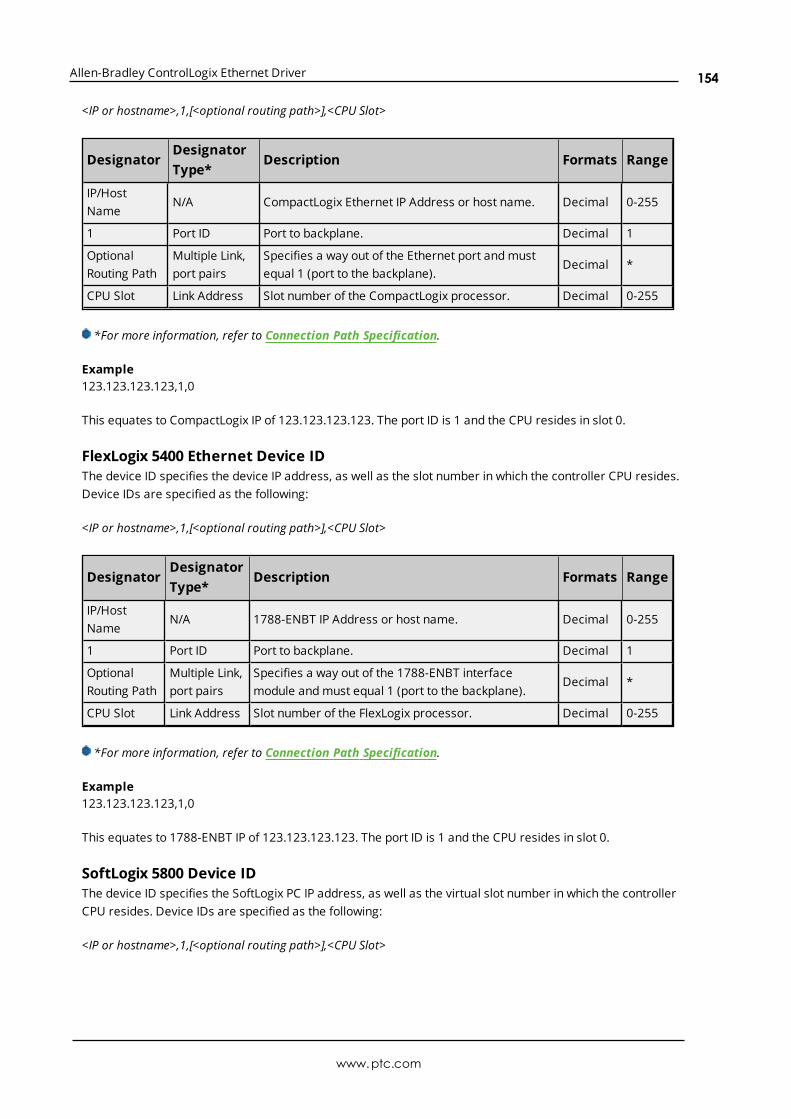
Allen-Bradley ControlLogix Ethernet Driver
<IP or hostname>,1,[<optional routing path>],<CPU Slot>
DesignatorDesignatorType*
Description Formats Range
IP/HostName
N/A CompactLogix Ethernet IP Address or host name. Decimal 0-255
1 Port ID Port to backplane. Decimal 1
OptionalRouting Path
Multiple Link,port pairs
Specifies a way out of the Ethernet port and mustequal 1 (port to the backplane).
Decimal *
CPU Slot Link Address Slot number of the CompactLogix processor. Decimal 0-255
*For more information, refer to Connection Path Specification.
Example123.123.123.123,1,0
This equates to CompactLogix IP of 123.123.123.123. The port ID is 1 and the CPU resides in slot 0.
FlexLogix 5400 Ethernet Device IDThe device ID specifies the device IP address, as well as the slot number in which the controller CPU resides.Device IDs are specified as the following:
<IP or hostname>,1,[<optional routing path>],<CPU Slot>
DesignatorDesignatorType*
Description Formats Range
IP/HostName
N/A 1788-ENBT IP Address or host name. Decimal 0-255
1 Port ID Port to backplane. Decimal 1
OptionalRouting Path
Multiple Link,port pairs
Specifies a way out of the 1788-ENBT interfacemodule and must equal 1 (port to the backplane).
Decimal *
CPU Slot Link Address Slot number of the FlexLogix processor. Decimal 0-255
*For more information, refer to Connection Path Specification.
Example123.123.123.123,1,0
This equates to 1788-ENBT IP of 123.123.123.123. The port ID is 1 and the CPU resides in slot 0.
SoftLogix 5800 Device IDThe device ID specifies the SoftLogix PC IP address, as well as the virtual slot number in which the controllerCPU resides. Device IDs are specified as the following:
<IP or hostname>,1,[<optional routing path>],<CPU Slot>
www.ptc.com
154
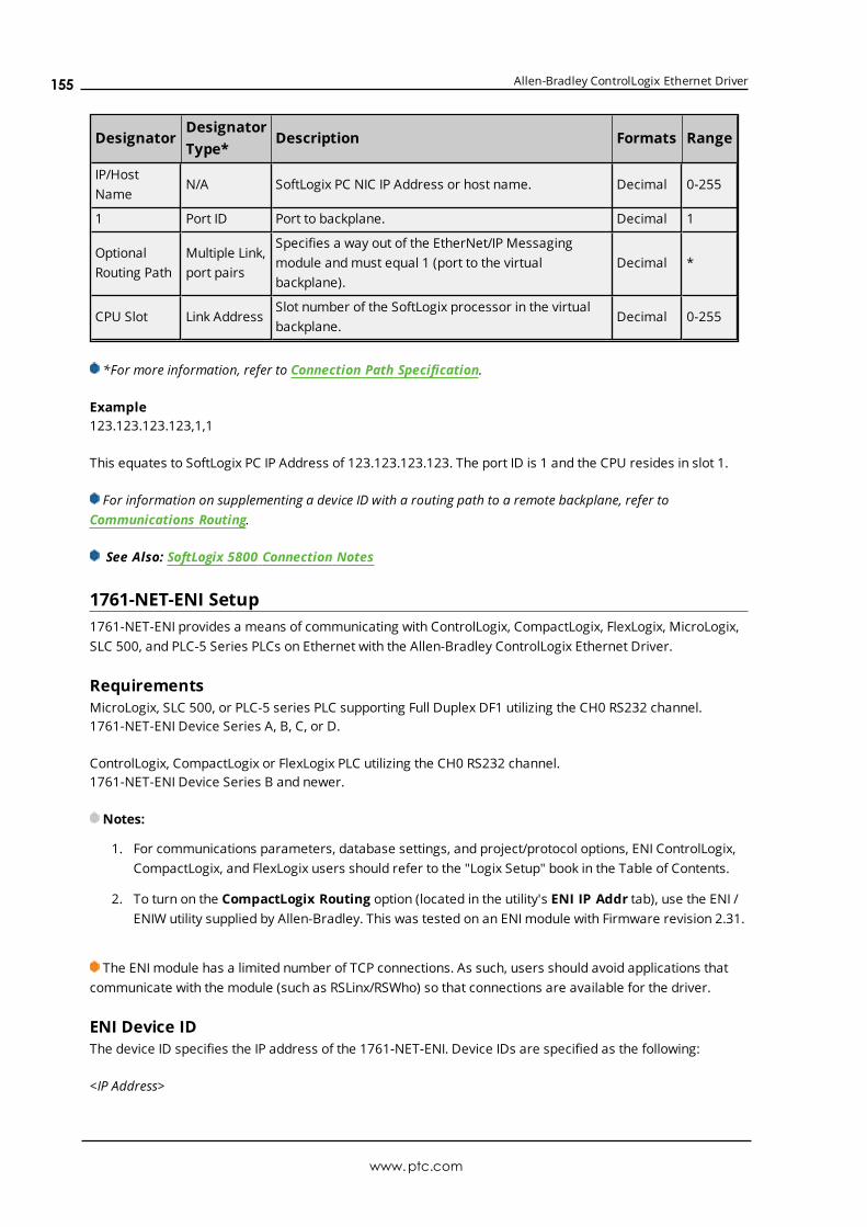
Allen-Bradley ControlLogix Ethernet Driver
DesignatorDesignatorType*
Description Formats Range
IP/HostName
N/A SoftLogix PC NIC IP Address or host name. Decimal 0-255
1 Port ID Port to backplane. Decimal 1
OptionalRouting Path
Multiple Link,port pairs
Specifies a way out of the EtherNet/IP Messagingmodule and must equal 1 (port to the virtualbackplane).
Decimal *
CPU Slot Link AddressSlot number of the SoftLogix processor in the virtualbackplane.
Decimal 0-255
*For more information, refer to Connection Path Specification.
Example123.123.123.123,1,1
This equates to SoftLogix PC IP Address of 123.123.123.123. The port ID is 1 and the CPU resides in slot 1.
For information on supplementing a device ID with a routing path to a remote backplane, refer toCommunications Routing.
See Also: SoftLogix 5800 Connection Notes
1761-NET-ENI Setup1761-NET-ENI provides a means of communicating with ControlLogix, CompactLogix, FlexLogix, MicroLogix,SLC 500, and PLC-5 Series PLCs on Ethernet with the Allen-Bradley ControlLogix Ethernet Driver.
RequirementsMicroLogix, SLC 500, or PLC-5 series PLC supporting Full Duplex DF1 utilizing the CH0 RS232 channel.1761-NET-ENI Device Series A, B, C, or D.
ControlLogix, CompactLogix or FlexLogix PLC utilizing the CH0 RS232 channel.1761-NET-ENI Device Series B and newer.
Notes:
1. For communications parameters, database settings, and project/protocol options, ENI ControlLogix,CompactLogix, and FlexLogix users should refer to the "Logix Setup" book in the Table of Contents.
2. To turn on the CompactLogix Routing option (located in the utility's ENI IP Addr tab), use the ENI /ENIW utility supplied by Allen-Bradley. This was tested on an ENI module with Firmware revision 2.31.
The ENI module has a limited number of TCP connections. As such, users should avoid applications thatcommunicate with the module (such as RSLinx/RSWho) so that connections are available for the driver.
ENI Device IDThe device ID specifies the IP address of the 1761-NET-ENI. Device IDs are specified as the following:
<IP Address>
www.ptc.com
155

Allen-Bradley ControlLogix Ethernet Driver
Designator Designator Type Description Formats Range
IP Address N/A 1761-NET-ENI IP address Decimal 0-255
Example123.123.123.123
This equates to an ENI IP of 123.123.123.123. Since the device only supports Full Duplex DF1, a node ID is notrequired.
For more information on communications parameters, refer to Logix Communications Parameters.
Data Highway Plus Gateway SetupDH+ Gateway provides a means of communicating with SLC 500 and PLC-5 series PLC on DH+ with theAllen-Bradley ControlLogix Ethernet Driver.
RequirementsEtherNet/IP Interface module.1756-DHRIO Interface Module with appropriate channel configured for DH+.SLC500 or PLC-5 series PLC on DH+ network.
Note: DH+ Gateway models do not support automatic tag database generation.
DH+ Gateway Device IDThe device ID specifies the device IP address as well as the DH+ parameters necessary for making aconnection. Device IDs are specified as the following:
<IP or hostname>,1,[<optional routing path>],<DHRIO Slot>.<DHRIO Channel>.<DH+ Node ID (dec)>
DesignatorDesignatorType*
Description Formats Range
IP/HostName
N/A IP Address or host name. Decimal 0-255
1 Port ID Port to backplane. Decimal 1
OptionalRouting Path
Multiple Link,port pairs
Specifies a way out of the EtherNet/IP interfacemodule and must equal 1 (port to the backplane).
Decimal *
DHRIO Slot Link Address Slot number of the 1756-DHRIO interface module. Decimal 0-255
DHRIOChannel
DH+ channel to use. AlphaA andB
DH+ Node ID DH+ node ID of target PLC in Decimal Format.** Decimal 0-99
*For more information, refer to Connection Path Specification.**For more information, refer to "Node ID Octal Addressing" below.
Example123.123.123.123,1,2.A.3
This equates to an Ethernet/IP of 123.123.123.123. The DH+ card resides in slot 2: use DH+ channel A andaddressing target DH+ Node ID 3 (dec).
www.ptc.com
156
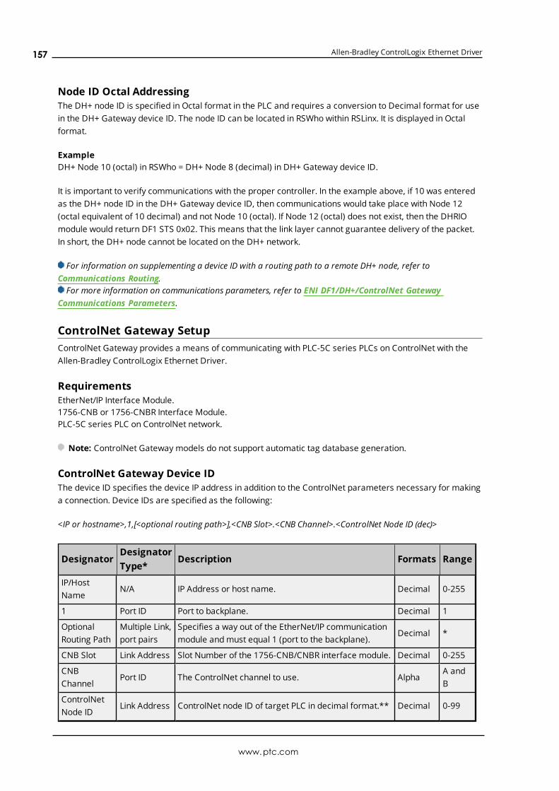
Allen-Bradley ControlLogix Ethernet Driver
Node ID Octal AddressingThe DH+ node ID is specified in Octal format in the PLC and requires a conversion to Decimal format for usein the DH+ Gateway device ID. The node ID can be located in RSWho within RSLinx. It is displayed in Octalformat.
ExampleDH+ Node 10 (octal) in RSWho = DH+ Node 8 (decimal) in DH+ Gateway device ID.
It is important to verify communications with the proper controller. In the example above, if 10 was enteredas the DH+ node ID in the DH+ Gateway device ID, then communications would take place with Node 12(octal equivalent of 10 decimal) and not Node 10 (octal). If Node 12 (octal) does not exist, then the DHRIOmodule would return DF1 STS 0x02. This means that the link layer cannot guarantee delivery of the packet.In short, the DH+ node cannot be located on the DH+ network.
For information on supplementing a device ID with a routing path to a remote DH+ node, refer toCommunications Routing.For more information on communications parameters, refer to ENI DF1/DH+/ControlNet Gateway
Communications Parameters.
ControlNet Gateway SetupControlNet Gateway provides a means of communicating with PLC-5C series PLCs on ControlNet with theAllen-Bradley ControlLogix Ethernet Driver.
RequirementsEtherNet/IP Interface Module.1756-CNB or 1756-CNBR Interface Module.PLC-5C series PLC on ControlNet network.
Note: ControlNet Gateway models do not support automatic tag database generation.
ControlNet Gateway Device IDThe device ID specifies the device IP address in addition to the ControlNet parameters necessary for makinga connection. Device IDs are specified as the following:
<IP or hostname>,1,[<optional routing path>],<CNB Slot>.<CNB Channel>.<ControlNet Node ID (dec)>
DesignatorDesignatorType*
Description Formats Range
IP/HostName
N/A IP Address or host name. Decimal 0-255
1 Port ID Port to backplane. Decimal 1
OptionalRouting Path
Multiple Link,port pairs
Specifies a way out of the EtherNet/IP communicationmodule and must equal 1 (port to the backplane).
Decimal *
CNB Slot Link Address Slot Number of the 1756-CNB/CNBR interface module. Decimal 0-255
CNBChannel
Port ID The ControlNet channel to use. AlphaA andB
ControlNetNode ID
Link Address ControlNet node ID of target PLC in decimal format.** Decimal 0-99
www.ptc.com
157

Allen-Bradley ControlLogix Ethernet Driver
*For more information, refer to Connection Path Specification.**For more information, refer to "Node ID Octal Addressing" below.
Example123.123.123.123,1,2.A.3
This equates to an Ethernet/IP of 123.123.123.123. The ControlNet card resides in slot 2: use ControlNetchannel A and addressing target ControlNet Node ID 3.
Node ID Octal AddressingThe ControlNet node ID is specified in Octal format in the PLC and requires a conversion to Decimal formatfor use in the ControlNet Gateway device ID. The node ID can be located in RSWho within RSLinx. It isdisplayed in Octal format.
ExampleCN node 10 (octal) in RSWho = CN node 8 (decimal) in ControlNet Gateway device ID.
It is important to verify communications with the proper controller. In the example above, if 10 was enteredas the ControlNet node ID in the ControlNet Gateway device ID, communications take place with Node 12(octal equivalent of 10 decimal), not Node 10 (octal). If Node 12 (octal) does not exist, the CNB modulereturns DF1 STS 0x02. This means that the link layer could not guarantee delivery of the packet. In short, theControlNet node could not be located on the ControlNet network.
Notes:
1. For more information on supplementing a device ID with a routing path to remote ControlNet node,refer to Communications Routing.
2. For more information on communications parameters, refer to ENI DF1/DH+/ControlNet GatewayCommunications Parameters.
EtherNet/IP Gateway SetupEtherNet/IP Gateway provides a means of communicating with MicroLogix, SLC 500, and PLC-5 series PLC onEtherNet/IP with the Allen-Bradley ControlLogix Ethernet Driver.
Requirements2 or more EtherNet/IP Interface modules (such as 1756-ENBT).MicroLogix, SLC500, or PLC-5 series PLC with EtherNet/IP connectivity.
Note: EthernetIP Gateway models do not support automatic tag database generation.
EtherNet/IP Gateway Device IDThe device ID specifies the local device IP address as well as the remote EtherNet/IP address necessary formaking a connection. Device IDs are specified as the following:
<IP or hostname>,1,[<optional routing path>],<ENBT Slot>.<ENBT Channel>.<Remote IP>
DesignatorDesignatorType*
Description Formats Range
IP/Host Name N/A IP Address or host name of the local EtherNet/IP Decimal 0-255
www.ptc.com
158

Allen-Bradley ControlLogix Ethernet Driver
DesignatorDesignatorType*
Description Formats Range
interface module.
1 Port ID Port to backplane. Decimal 1
OptionalRouting Path
Multiple Link,port pairs
Specifies a way out of the EtherNet/IP interfacemodule and must equal 1 (port to the backplane).
Decimal *
ENBT Slot Link AddressThe slot number of the second EtherNet/IP interfacemodule.
Decimal 0-255
ENBT Channel Port ID The Ethernet/IP port to use. AlphaA andB
RemoteIP Address
Link Address The remote IP address of the target PLC. Decimal 0-255
*For more information, refer to Connection Path Specification.
Example123.123.123.123,1,2.A.192.168.1.10
This equates to a local IP of 123.123.123.123. The second Ethernet/IP card resides in slot 2: use port A andaddressing target device with IP 192.168.1.10.
Notes:
1. For information on supplementing a device ID with a routing path to a remote Ethernet/IP device,refer to Communications Routing.
2. For more information on communications parameters, refer to ENI DF1/DH+/ControlNet GatewayCommunications Parameters.
3. When configuring the device ID, users should verify that the device can be detected using the sameroute through RSLinx.
Serial Gateway SetupSerial Gateway provides a means of communicating with ControlLogix, CompactLogix, FlexLogix, andSoftLogix PLCs on a serial network with the Allen-Bradley ControlLogix Ethernet Driver.
RequirementsEtherNet/IP Interface module.Local CPU with a serial port.Remote ControlLogix, CompactLogix, FlexLogix, or SoftLogix CPU with a serial port.
Notes:
1. Local and Remote CPUs must be on the same serial network.
2. Serial Gateway models do not support automatic tag database generation.
Serial Gateway Device IDThe device ID specifies the local device IP address as well as the remote device station ID necessary formaking a connection. Device IDs are specified as the following:
www.ptc.com
159

Allen-Bradley ControlLogix Ethernet Driver
<IP or hostname>,1,[<Optional Routing Path>],<CPU Slot>.<Serial Port Channel>.<Station ID (dec)>
DesignatorDesignatorType*
Description Formats Range
IP/HostName
N/A IP address or host name. Decimal 0-255
1 Port ID Port to backplane. Decimal 1
OptionalRouting Path
Multiple Link,port pairs
Specifies a way out of the EtherNet/IP interfacemodule and must equal 1 (port to the backplane).
Decimal *
CPU Slot Link AddressSlot number of the CPU module that contains theserial port used for communications.
Decimal 0-255
Serial PortChannel
Serial port channel to use. AlphaA andB
Station ID DF1 station ID of target PLC in Decimal Format.** Decimal 0-255
*For more information, refer to Connection Path Specification.
Example123.123.123.123,1,0.A.3
This equates to an Ethernet/IP of 123.123.123.123. The CPU card resides in slot 0: use Channel A (serialport) and addressing target station ID 3 (dec).
Notes:
1. For information on supplementing a Device ID with a routing path to a remote serial node, refer toCommunications Routing.
2. For more information on communications parameters, refer to Logix CommunicationsParameters.
3. When configuring the Device ID, users should verify that the device can be detected using the sameroute through RSLinx.
MicroLogix 1100 SetupMicroLogix 1100 Device IDThe Device ID specifies the IP address of the MicroLogix 1100. Device IDs are specified as the following:
<IP or hostname>
Designator Designator Type Description Formats Range
IP/Host Name N/A IP Address or host name. Decimal 0-255
Example123.123.123.123
This equates to an IP of 123.123.123.123.
www.ptc.com
160

Allen-Bradley ControlLogix Ethernet Driver
For more information on communications parameters, refer to ENI DF1/DH+/ControlNet GatewayCommunications Parameters.
Communications RoutingRouting provides a way to communicate with a remote device over various networks. It can be thought of asa bridge between the local device and a remote device even if they are on two different field bus networks.Access to a remote (destination) backplane allows for direct communication with the supported moduleslocated on this backplane. Supported modules include the following:
l ControlLogix 5500 processor for ControlLogix applications.
l SoftLogix 5800 processor for SoftLogix applications.
l 1756-DHRIO interface module for DH+ Gateway applications.
l 1756-CNB or 1756-CNBR interface module for ControlNet Gateway applications.
A routing path is a series of backplane hops, whose last hop points to the destination backplane. Each hoprequires a Logix backplane (not a Logix processor). An individual hop can utilize one of the followingnetworks as its medium:
l ControlNet
l DH+
l TCP/IP (Ethernet/IP)
Important: Routing is not supported for ENI and MicroLogix 1100 models.
Connection Path SpecificationThe routing path is specified in the device ID. As with non-routing applications, communication originatesfrom the Allen-Bradley ControlLogix Ethernet Driver on the PC and is directed at the local Ethernet module.Once at this local Ethernet module, the device ID specifies a way out of the module and onto the backplane,just like with non-routing applications. The routing path directs the message to the desired Logix backplane.The device ID also determines what device is communicated with (such as the ControlLogix processor,SoftLogix processor, DH+ node, or ControlNet node).
The routing path specification begins and ends with the left and right bracket respectively ([ ]). The path itselfis a series of port/link address pairs, identical to the communication path syntax in RSLogix 5000 MessageConfiguration dialog.
DesignatorType
Description Formats Range
Port ID Specifies a way out of the interface module in question.* Decimal0-65535
Link Address
If the corresponding port is the backplane, the link address is the slotnumber of the interface module that goes out.
If the corresponding port is an interface module port, the link addressspecifies a destination node as follows.- DH+/ControlNet: node ID- EtherNet/IP communication module: IP address- SoftLogix EtherNet/IP module: IP address
Decimal 0-255
*For more information, refer to "Port Reference" below.
www.ptc.com
161

Allen-Bradley ControlLogix Ethernet Driver
Single HopIP Address, Port ID0, [Link Address0, Port ID1, Link Address1, Port ID2], Link Address2.
Multi-Hop (N Hops)IP Address, Port ID0, [Link Address0, Port ID1, Link Address1, Port ID2, Link Address2, ... Port ID(N+1), LinkAddress(N+1), Port ID(N+2)], Link Address(N+2).
Notes:
1. The last port ID in the path (Port ID2 and Port ID(N+2) for single-hop and multi-hop respectively) mustbe 1 (port for backplane).
2. Port ID0 must be 1 (port for backplane). Link Address2 and Link Address (N+2) are the slot numbersof the remote Logix processor/1756-DHRIO module/1756-CNB module.
Port ReferenceInterface Module Port 1 Port 2 Port 3
EtherNet/IP Communication Module Backplane Ethernet Network N/A
SoftLogix EtherNet/IP MessagingModule
VirtualBackplane
Ethernet Network N/A
1756-DHRIO Backplane DH+ Network on Ch.A
DH+ Network on Ch.B
1756-CNB Backplane ControlNet Network N/A
Application Notes
1. Messages cannot be routed in or out of the same interface module channel more than once withinthe path. Doing so results in CIP error 0x01 Ext. error 0x100B.
2. For multiple channel interface modules, messages cannot be routed into and then immediately out ofthat same module (using different channels), regardless of whether the message is directed to thebackplane first or avoids the backplane all together. As previously mentioned, the latter is notsupported since each hop requires a ControlLogix backplane. An example would be to route a DH+message from one DH+ link (such as Channel A of 1756-DHRIO) to another DH+ link (such asChannel B of same 1756-DHRIO) through one 1756-DHRIO-interface module. This is commonlyreferred to as Remote DH+ messaging and is not supported.
Routing ExamplesThe routing examples below include the entire device ID minus the IP of the local 1756-ENBT. Theperspective of the device ID/routing path is from the local 1756-ENBT Module. Hop descriptions are in thefollowing form:
Link Address (N), Port ID(N+1), Link Address(N+1), Port ID(N+2)
For more information, refer to Connection Path Specification. For further details on building aconnection/routing path, refer to Allen-Bradley Publication 1756-6.5.14, pp. 4-5 through 4-8.
In the illustration below, all DH+/ControlNet node IDs are specified in Decimal format. The node ID specifiedin the PLC and displayed in RSWho is in Octal format. Descriptions of the colors are as follows:
www.ptc.com
162

Allen-Bradley ControlLogix Ethernet Driver
l Green = Ethernet
l Blue = DH+
l Orange = ControlNet
For more information, refer to Data Highway Plus Gateway Setup and ControlNet Gateway Setup.
Example 1Logix5550 to PLC-5 via DH+ Gateway.
www.ptc.com
163

Allen-Bradley ControlLogix Ethernet Driver
Destination Node Model Routing Device ID less IP
PLC-5/20 (D) DH+ Gateway No 1,1.B.9
Example 2Logix5550 to PLC-5C via CN Gateway.
Destination Node Model Routing Device ID less IP
PLC-5/40C (B) CN Gateway No 1,2.A.1
Example 3Logix5550 to Logix5550 via routing over DH+.
Destination Node Model Routing Device ID less IP
Logix5550 (C) ControlLogix 5550 Yes 1,[1,2,8,1],0
Routing Path Breakdown for Example 3.
Hop Segment Description
1 1,2,8,1 Slot 1 (DHRIO) -> Port 2 (DH+ Ch A) -> DH+ Node 8 -> Logix C backplane
Example 4Logix5550 to PLC-5C via CN Gateway, routing over DH+.
Destination Node Model Routing Device ID less IP
PLC-5/80C (E) CN Gateway Yes 1,[1,2,8,1],2.A.3
Routing Path Breakdown for Example 4.
Hop Segment Description
1 1,2,8,1 Slot 1 (DHRIO) -> Port 2 (DH+ Ch A) -> DH+ Node 8 -> Logix C backplane
Example 5Logix5550 to Logix5550 via routing over DH+, ControlNet
Destination Node Model Routing Device ID less IP
Logix5550 (F) ControlLogix 5550 Yes 1,[1,2,8,1,2,2,15,1],0
Routing Path Breakdown for Example 5.
Hop Segment Description
1 1,2,8,1 Slot 1 (DHRIO) -> Port 2 (DH+ Ch A) -> DH+ Node 8 -> Logix C backplane
2 2,2,15,1 Slot 2 (CNB) -> Port 2 (CN Ch A) -> CN Node 15 -> Logix F backplane
Example 6
www.ptc.com
164
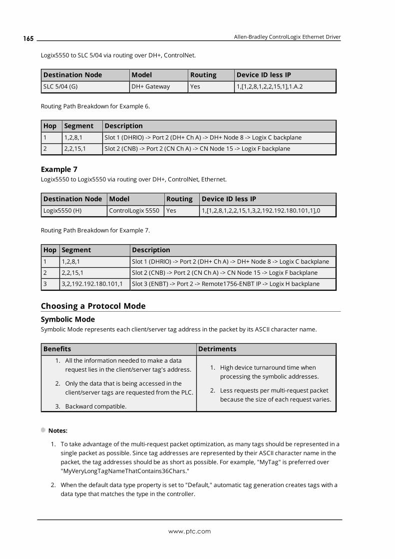
Allen-Bradley ControlLogix Ethernet Driver
Logix5550 to SLC 5/04 via routing over DH+, ControlNet.
Destination Node Model Routing Device ID less IP
SLC 5/04 (G) DH+ Gateway Yes 1,[1,2,8,1,2,2,15,1],1.A.2
Routing Path Breakdown for Example 6.
Hop Segment Description
1 1,2,8,1 Slot 1 (DHRIO) -> Port 2 (DH+ Ch A) -> DH+ Node 8 -> Logix C backplane
2 2,2,15,1 Slot 2 (CNB) -> Port 2 (CN Ch A) -> CN Node 15 -> Logix F backplane
Example 7Logix5550 to Logix5550 via routing over DH+, ControlNet, Ethernet.
Destination Node Model Routing Device ID less IP
Logix5550 (H) ControlLogix 5550 Yes 1,[1,2,8,1,2,2,15,1,3,2,192.192.180.101,1],0
Routing Path Breakdown for Example 7.
Hop Segment Description
1 1,2,8,1 Slot 1 (DHRIO) -> Port 2 (DH+ Ch A) -> DH+ Node 8 -> Logix C backplane
2 2,2,15,1 Slot 2 (CNB) -> Port 2 (CN Ch A) -> CN Node 15 -> Logix F backplane
3 3,2,192.192.180.101,1 Slot 3 (ENBT) -> Port 2 -> Remote1756-ENBT IP -> Logix H backplane
Choosing a Protocol ModeSymbolic ModeSymbolic Mode represents each client/server tag address in the packet by its ASCII character name.
Benefits Detriments
1. All the information needed to make a datarequest lies in the client/server tag's address.
2. Only the data that is being accessed in theclient/server tags are requested from the PLC.
3. Backward compatible.
1. High device turnaround time whenprocessing the symbolic addresses.
2. Less requests per multi-request packetbecause the size of each request varies.
Notes:
1. To take advantage of the multi-request packet optimization, as many tags should be represented in asingle packet as possible. Since tag addresses are represented by their ASCII character name in thepacket, the tag addresses should be as short as possible. For example, "MyTag" is preferred over"MyVeryLongTagNameThatContains36Chars."
2. When the default data type property is set to "Default," automatic tag generation creates tags with adata type that matches the type in the controller.
www.ptc.com
165
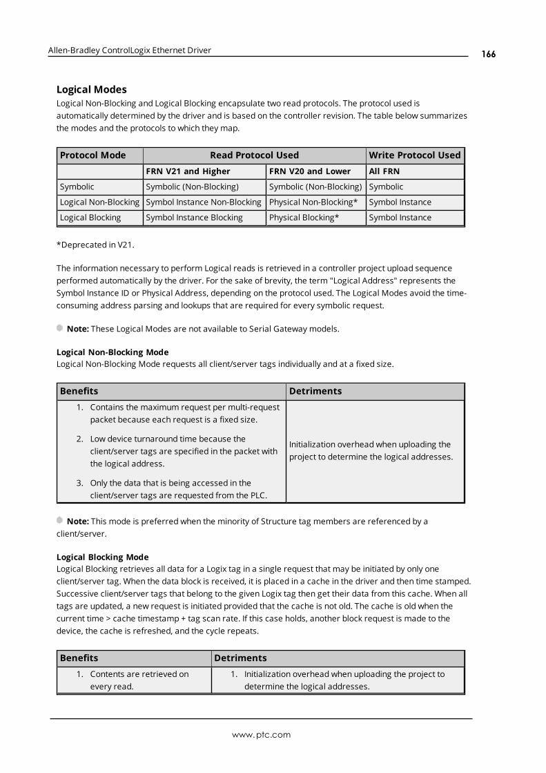
Allen-Bradley ControlLogix Ethernet Driver
Logical ModesLogical Non-Blocking and Logical Blocking encapsulate two read protocols. The protocol used isautomatically determined by the driver and is based on the controller revision. The table below summarizesthe modes and the protocols to which they map.
Protocol Mode Read Protocol Used Write Protocol Used
FRN V21 and Higher FRN V20 and Lower All FRN
Symbolic Symbolic (Non-Blocking) Symbolic (Non-Blocking) Symbolic
Logical Non-Blocking Symbol Instance Non-Blocking Physical Non-Blocking* Symbol Instance
Logical Blocking Symbol Instance Blocking Physical Blocking* Symbol Instance
*Deprecated in V21.
The information necessary to perform Logical reads is retrieved in a controller project upload sequenceperformed automatically by the driver. For the sake of brevity, the term "Logical Address" represents theSymbol Instance ID or Physical Address, depending on the protocol used. The Logical Modes avoid the time-consuming address parsing and lookups that are required for every symbolic request.
Note: These Logical Modes are not available to Serial Gateway models.
Logical Non-Blocking ModeLogical Non-Blocking Mode requests all client/server tags individually and at a fixed size.
Benefits Detriments
1. Contains the maximum request per multi-requestpacket because each request is a fixed size.
2. Low device turnaround time because theclient/server tags are specified in the packet withthe logical address.
3. Only the data that is being accessed in theclient/server tags are requested from the PLC.
Initialization overhead when uploading theproject to determine the logical addresses.
Note: This mode is preferred when the minority of Structure tag members are referenced by aclient/server.
Logical Blocking ModeLogical Blocking retrieves all data for a Logix tag in a single request that may be initiated by only oneclient/server tag. When the data block is received, it is placed in a cache in the driver and then time stamped.Successive client/server tags that belong to the given Logix tag then get their data from this cache. When alltags are updated, a new request is initiated provided that the cache is not old. The cache is old when thecurrent time > cache timestamp + tag scan rate. If this case holds, another block request is made to thedevice, the cache is refreshed, and the cycle repeats.
Benefits Detriments
1. Contents are retrieved onevery read.
1. Initialization overhead when uploading the project todetermine the logical addresses.
www.ptc.com
166

Allen-Bradley ControlLogix Ethernet Driver
Benefits Detriments
2. Low device turnaround timebecause the client/server tagsare specified in the packet withthe logical address.
3. Contains the maximum requestper multi-request packetbecause each request is a fixedsize.
2. If the minority of Logix tags are referenced, it is slowerthan Logical Non-Blocking Mode (because more data isbeing accessed from the PLC than referenced in theclient/server tags).
Note: This mode is preferred when the majority of Structure tag members are referenced by aclient/server.
See Also: Performance Statistics and Tuning
Symbol Instance vs. Physical ProtocolSymbol Instance reads are CIP requests wherein the CIP Instance ID is used to specify a Native tag in a readrequest. In Non-Blocking Mode, the CIP Member ID may be required to fully qualify the path to structuremembers and array elements. For example, the CIP Instance ID would represent the structure whereas theCIP Member ID represents the member within the structure. Because of the addition of CIP Member IDsrequired to fully qualify a client/server tag, requests can vary in size. The deeper the nesting of structures,the more CIP Member IDS required to specify it and the fewer requests that fit in a single packet. SymbolInstance reads were introduced in FRN V21.
Physical reads are CIP requests wherein the DMA address is used to specify a Native tag in a read request.In Non-Blocking Mode, the byte offset may be required to fully qualify the path to structure members andarray element. For example, the starting DMA address would represent the structure whereas the byteoffset represents the member within the structure. Ultimately the start + offset is the DMA address specifiedin the request: all requests are fixed in size (unlike Symbol Instance reads). No matter how deep structuresare nested, the request is the same size in the packet. Physical reads have been deprecated as of FRN V21.
Detecting a Change in the Controller ProjectThe Allen-Bradley ControlLogix Ethernet Driver monitors for project changes and can detect downloads inprogress, online edits, and offline edits. When the protocol is set to Logical, users have the option tosynchronize the driver's project image with that of the controller project. Synchronization ensures that thedriver uses the current logical address for each Native tag when performing reads and writes.
l Downloads in Progress: The driver monitors for both online and offline edits in every request. Itdetects if a download occurs while actively reading or writing to Native tags, then follows a project-change procedure depending on its mode. To enable this synchronization, right-click on the deviceand select Properties. In the Logix Options, locate either Online Edits or Offline Edits and selectYes.
l Online Edits: The driver monitors for online edits in every request. It detects if an online edit occurswith the controller on the following read or write operation, then follows a project-change proceduredepending on its mode. To enable this synchronization, right-click on the device and selectProperties. In Logix Options, locate Online Edits and select Yes.
l Offline Edits: The driver monitors for offline edits in every request. It detects if an offline edit occurswith the controller on the following read or write operation, then follows a project-change procedure
www.ptc.com
167
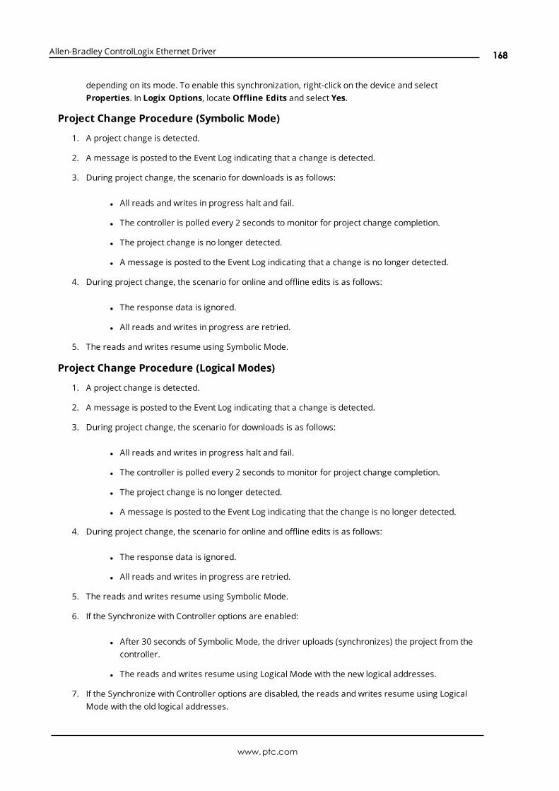
Allen-Bradley ControlLogix Ethernet Driver
depending on its mode. To enable this synchronization, right-click on the device and selectProperties. In Logix Options, locate Offline Edits and select Yes.
Project Change Procedure (Symbolic Mode)
1. A project change is detected.
2. A message is posted to the Event Log indicating that a change is detected.
3. During project change, the scenario for downloads is as follows:
l All reads and writes in progress halt and fail.
l The controller is polled every 2 seconds to monitor for project change completion.
l The project change is no longer detected.
l A message is posted to the Event Log indicating that a change is no longer detected.
4. During project change, the scenario for online and offline edits is as follows:
l The response data is ignored.
l All reads and writes in progress are retried.
5. The reads and writes resume using Symbolic Mode.
Project Change Procedure (Logical Modes)
1. A project change is detected.
2. A message is posted to the Event Log indicating that a change is detected.
3. During project change, the scenario for downloads is as follows:
l All reads and writes in progress halt and fail.
l The controller is polled every 2 seconds to monitor for project change completion.
l The project change is no longer detected.
l A message is posted to the Event Log indicating that the change is no longer detected.
4. During project change, the scenario for online and offline edits is as follows:
l The response data is ignored.
l All reads and writes in progress are retried.
5. The reads and writes resume using Symbolic Mode.
6. If the Synchronize with Controller options are enabled:
l After 30 seconds of Symbolic Mode, the driver uploads (synchronizes) the project from thecontroller.
l The reads and writes resume using Logical Mode with the new logical addresses.
7. If the Synchronize with Controller options are disabled, the reads and writes resume using LogicalMode with the old logical addresses.
www.ptc.com
168

Allen-Bradley ControlLogix Ethernet Driver
www.ptc.com
169
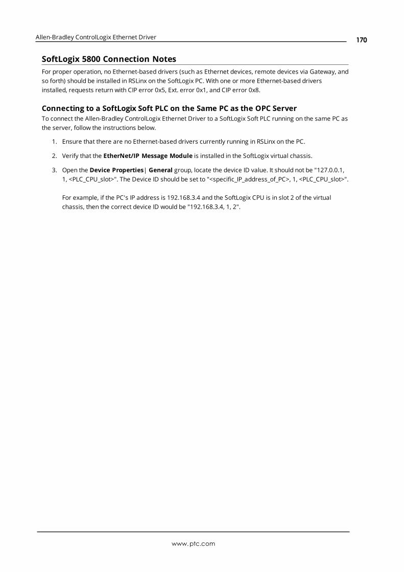
Allen-Bradley ControlLogix Ethernet Driver
SoftLogix 5800 Connection NotesFor proper operation, no Ethernet-based drivers (such as Ethernet devices, remote devices via Gateway, andso forth) should be installed in RSLinx on the SoftLogix PC. With one or more Ethernet-based driversinstalled, requests return with CIP error 0x5, Ext. error 0x1, and CIP error 0x8.
Connecting to a SoftLogix Soft PLC on the Same PC as the OPC ServerTo connect the Allen-Bradley ControlLogix Ethernet Driver to a SoftLogix Soft PLC running on the same PC asthe server, follow the instructions below.
1. Ensure that there are no Ethernet-based drivers currently running in RSLinx on the PC.
2. Verify that the EtherNet/IP Message Module is installed in the SoftLogix virtual chassis.
3. Open the Device Properties| General group, locate the device ID value. It should not be "127.0.0.1,1, <PLC_CPU_slot>". The Device ID should be set to "<specific_IP_address_of_PC>, 1, <PLC_CPU_slot>".
For example, if the PC's IP address is 192.168.3.4 and the SoftLogix CPU is in slot 2 of the virtualchassis, then the correct device ID would be "192.168.3.4, 1, 2".
www.ptc.com
170
Allen-Bradley ControlLogix Ethernet Driver
Index
-
----------------------------------------------------------------------------------------------------- 150
%
%s | CHANNEL STATISTICS 150
%s | DEVICE STATISTICS 150
0
0000-Generic Module 32
0x0001 Extended Error Codes 115
0x001F Extended Error Codes 116
0x00FF Extended Error Codes 116
0x01 114
0x02 114
0x03 114
0x04 114
0x05 114
0x06 114
0x07 114
0x08 114
0x09 114
0x0A 114
0x0B 114
0x0C 114
0x0D 114
0x0E 114
0x0F 114
0x10 114
0x11 114
0x12 114
0x13 114
0x14 115
0x15 115
www.ptc.com
171

Allen-Bradley ControlLogix Ethernet Driver
0x1A 115
0x1B 115
0x1C 115
0x1D 115
0x1E 115
0x1F 115
0x22 115
0x25 115
0x26 115
0x27 115
1
1761-NET-ENI 155
A
Address Descriptions 53
Address Formats 62
Addressing Atomic Data Types 65
Addressing STRING Data Type 66
Addressing Structure Data Types 66
Advanced Addressing: BOOL 69
Advanced Addressing: DINT 75
Advanced Addressing: INT 73
Advanced Addressing: LINT 78
Advanced Addressing: SINT 70
Advanced Addressing:REAL 79
Advanced Channel Properties 18
Allow Function File Block Writes 30
Allow Sub Groups 25
Array Block Size 26
Array Count Limit 29
Array Tags 62, 109
ASCII Files 95
Attempts Before Timeout 23
Automatic Tag Database Generation 109
Avg. device turn-around time = <number> (milliseconds) 150
www.ptc.com
172

Allen-Bradley ControlLogix Ethernet Driver
Avg. packets received/sec = <number>. 150
Avg. packets sent/sec = <number>. 150
Avg. tag reads/sec = <number>. 150
Avg. tags/transaction = <number>. 150
B
BCD 51
BCD Files 97
Binary Files 91
Block read request failed due to a framing error. | Block size = <number> (bytes), Block name ='<name>'. 126
Block read request failed due to a framing error. | Block size = <number> (elements), Block start address= '<address>'. 126
Block Transfer Files 103
Boolean 51
Byte 51
C
Channel 0 Communication Status File 106
Channel 1 Communication Status File 107
Channel Assignment 20
Channel Properties — Ethernet Communications 17
Channel Properties — General 16
Channel Properties — Write Optimizations 17
Channel Setup 16
Char 51
Choosing a Protocol Mode 165
CIP connection timed out while uploading project information. 124
CIP Error Codes 114
Communication Protocol 16
Communications Routing 161
Communications Timeouts 22-23
CompactLogix 5300 Addressing for ENI 54
CompactLogix 5300 Addressing for Ethernet 54
CompactLogix 5300 Addressing for Serial Gateway 54
Connect Timeout 22
Connection Path Specification 161
www.ptc.com
173

Allen-Bradley ControlLogix Ethernet Driver
Connection Size 26
Control Files 93
Controller-to-Server Name Conversions 112
Controller not supported. | Vendor ID = <ID>, Product type = <type>, Product code = <code>, Productname = '<name>'. 125
ControlLogix 5000 Addressing 61
ControlLogix 5500 Addressing for ENI 54
ControlLogix 5500 Addressing for Ethernet 54
ControlLogix 5500 Addressing for Serial Gateway 54
ControlLogix 5500 Ethernet 153
ControlLogix Communications Parameters 26
ControlLogix Database Settings 28
ControlLogix Options 26
ControlNet (TM) Gateway 157
ControlNet Gateway Device ID 157
Counter Files 92
Create 25
Create from Device 28
Create from Import File 28
D
Data Collection 21
Data Types Description 51
Database error. Array tags renamed because they exceed max. character length. | Array tags = '<tags>',Max. length = <number>, New array tags = '<tags>'. 147
Database error. CIP connection timed out while uploading project information. 124
Database error. Data type for reference tag unknown. Setting alias tag data type to default. | Referencetag = '<tag>', Alias tag = '<tag>', Default data type = '<type>'. 117
Database error. Data type not found in tag import file. Tag not added. | Data type = '<type>', Tag name ='<tag>'. 118
Database error. Encapsulation error occurred during fwd. open request. | Encapsulation error =<code>. 119
Database error. Encapsulation error occurred during register session request. | Encapsulation error =<code>. 119
Database error. Encapsulation error occurred while uploading program information. | Program name ='<name>', Encapsulation error = <code>. 121
Database error. Encapsulation error occurred while uploading project information. | Encapsulation error= <code>. 119
Database error. Error occurred during forward open request. | CIP error = <code>, Extended error =<code>. 119
www.ptc.com
174
Allen-Bradley ControlLogix Ethernet Driver
Database error. Error occurred processing alias tag. Tag not added. | Alias tag = '<tag>'. 118
Database error. Error occurred while uploading program information. | Program name = '<name>', CIPerror = <code>, Extended error = <code>. 121
Database error. Error occurred while uploading project information. | CIP error = <code>, Extended error= <code>. 120
Database error. Framing error occurred during forward open request. 119
Database error. Framing error occurred during register session request. 119
Database error. Framing error occurred while uploading program information. | Program name ='<name>'. 122
Database error. Framing error occurred while uploading project information. 120
Database error. Internal error occurred. 121
Database error. Member data type not found in tag import file. Setting data type to default. | Memberdata type = '<type>', UDT = '<type>', Default data type '<type>'. 118
Database error. No more connections available for fwd. open request. 125
Database error. PLC5/SLC/MicroLogix devices do not support this function. 151
Database error. Program group name exceeds max. character length. Program group renamed. | Groupname = '<name>', Max. length = <number>, New group name = '<name>'. 147
Database error. Tag renamed because it exceeds max. character length. | Tag name = '<tag>', Max.length = <number>, New tag name = '<tag>'. 147
Database error. Unable to resolve CIP data type for tag. Setting to default type. | CIP data type = <type>,Tag name = '<tag>', Default data type = '<type>'. 122
Database Import Method 28
Database status. | Program count = <number>, Data type count = <number>, Imported tag count =<number>. 147
Database status. Building tag projects, please wait. | Tag project count = <number>. 147
Database status. Generating OPC tags. 147
Database status. Importing alias tags. 147
Database status. Importing non-alias tags. 146
Database status. Importing tags from .L5X file. | Schema revision = '<value>', Software revision ='<value>'. 148
Database status. Retrieving controller project. 147
DataHighwayPlus (TM) Gateway Setup 156
Date 51
Default Data Type Conditions 51
Delete 25
Demote on Failure 23
Demotion Period 23
Details. | IP = '<address>', Vendor ID = <vendor>, Product type = <type>, Product code = <code>,Revision= <value>, Product name = '<name>', Product S/N = <number>. 148
Detecting a Change in the Controller Project 167
Device not responding. Local node responded with error. | DF1 status = <code>. 143
www.ptc.com
175

Allen-Bradley ControlLogix Ethernet Driver
Device Properties — Auto-Demotion 23
Device Properties — Tag Generation 24
Device Setup 20
Device tag import aborted. 151
DH+ Gateway Device ID 156, 158
Diagnostics 17
Discard Requests when Demoted 24
Display Descriptions 28
Do Not Scan, Demand Poll Only 22
Double 51
Driver 17, 20
DRIVER STATISTICS 150
Duty Cycle 18
DWord 51
E
Elapsed time = <number> (seconds). 148
Encapsulation Error Codes 114
Encapsulation error occurred during a request to device. | Encapsulation error = <code>. 135
Encapsulation error occurred while uploading controller program information. Encapsulation error =<code>. 124
Encapsulation error occurred while uploading program information. | Program name = '<name>',Encapsulation error = <code>. 124
Encapsulation error occurred while uploading project information. | Encapsulation error = <code>. 122
ENI Device ID 155
ENI DF1/DH+/ControlNet Gateway Communications Parameters 29
Error Codes 114
Error occurred during a request to device. | CIP error = <code>, Extended error = <code>. 135
Error occurred while uploading controller program information. CIP error = <code>, Extended error =<code>. 124
Error occurred while uploading program information. | Program name = '<name>', CIP error = <code>,Extended error = <code>. 124
Error occurred while uploading project information. | CIP error = <code>, Extended error = <code>. 123
Error opening file for tag database import. | OS error = '<code>'. 125
Errors occurred retrieving controller project. 151
EtherNet/IP Gateway Setup 158
Event Log Messages 117
www.ptc.com
176

Allen-Bradley ControlLogix Ethernet Driver
F
File Listing 82
Filtering 29
FlexLogix 5400 Addressing for Serial Gateway 54
FlexLogix 5400 Addressing for ENI 54
FlexLogix 5400 Addressing for Ethernet 54
Float 51, 95
Float Files 95
Frame received from device contains errors. 125
Framing error occurred while uploading controller program information. 124
Framing error occurred while uploading program information. | Program name = '<name>'. 124
Framing error occurred while uploading project information. 123
Function Files 104
G
Generate 24
Global Tags 63
H
Help Contents 11
High-Speed Counter File (HSC) 104
I
I/O Module Status File (IOS) 107
ID 20
Identification 20
IEEE-754 floating point 19
Import file not found. 151
Impose Array Limit 29
Inactivity Watchdog 26
Initial Updates from Cache 22
Initialization transactions = <number>. 150
Input Files 86
www.ptc.com
177

Allen-Bradley ControlLogix Ethernet Driver
Input Words 31
Integer Files 94
Inter-Request Delay 23
Internal driver error occurred. 151
Internal Tags 64
Invalid or corrupt controller project detected while synchronizing. Synchronization will be retriedshortly. 117
Invalid or corrupt controller project detected while synchronizing. Try again later. 151
L
L5K file is invalid or corrupt. 151
L5X file is invalid or corrupt. 152
LBCD 51
Leading Underscores 112
Limit Name Length 29
Link Address 161
Logix Addressing 54, 61
Logix Advanced Addressing 69
Logix Communications Parameters 26
Logix Database Settings 28
Logix Device IDs 153
Logix Options 26
Logix Tag-Based Addressing 61
Long 51
Long Controller Program & Tag Names 109
Long Files 97
Low memory resources. 147, 151
M
Memory could not be allocated for tag. | Tag address = '<address>'. 135
Message Files 102
Micrologix 1100 Device ID 160
MicroLogix 1100 Setup 160
Micrologix Addressing 55
Micrologix Addressing for ENI 55
Micrologix Addressing for EtherNet/IP Gateway 55
MicroLogix Message Files 101
www.ptc.com
178
Allen-Bradley ControlLogix Ethernet Driver
MicroLogix PID Files 98
Model 20
Module 31
N
Network Adapter 17
Non-Normalized Float Handling 19
O
On Device Startup 24
On Duplicate Tag 25
On Property Change 24
Operating Mode 20
Optimization Method 18
Optimizing Communications 35
Optimizing the Application 37
Ordering of Logix Array Data 67
Output Files 83
Output Words 31
Overview 12
Overwrite 25
P
Packets received = <number>. 149
Packets sent = <number>. 149
Parent Group 25
Performance Optimizations 35
Performance Statistics 27
Performance Statistics and Tuning 38
Performance Tuning Example 39
Physical block cache reads = <number>. 149
Physical block device reads = <number>. 149
Physical non-block device reads = <number>. 149
Physical non-block, array block cache reads = <number>. 149
Physical non-block, array block device reads = <number>. 149
www.ptc.com
179

Allen-Bradley ControlLogix Ethernet Driver
PID Files 99
PLC-5 Series Addressing 59
PLC-5 Series Addressing for ControlNet 59
PLC-5 Series Addressing for EtherNet/IP Gateway 60
Port ID 161
Predefined Term Tags 64
Preparing for Automatic Tag Database Generation 112
Program Tags 63
Project download complete. 145
Project download detected while synchronizing. Synchronization will be retried shortly. 117
Project download detected while synchronizing. Try again later. 151
Project download in progress or no project exists. 144
Project offline edit detected. 145
Project online edit detected. 145
Project Options 27
Protocol 27
Protocol Mode 27
R
Read request for tag failed due to a framing error. | Tag address = '<address>'. 126
Read/Write transactions = <number>. 150
Real-Time Clock File (RTC) 105
Redundancy 32
Reference Material 153
Request All Data at Scan Rate 22
Request Data No Faster than Scan Rate 22
Request Size 29
Request Timeout 22
Requested CIP connection size is not supported by this device. Automatically falling back to max. size. |Requested size = <number> (bytes), Max. size = <number> (bytes). 146
Respect Client-Specified Scan Rate 22
Respect Tag-Specified Scan Rate 22
Routing Examples 162
S
Scan Mode 21
Serial Gateway Device ID 159
www.ptc.com
180

Allen-Bradley ControlLogix Ethernet Driver
Serial Gateway Setup 159
Setup 14
Short 51
Simulated 21
SLC 500 Fixed I/O Addressing 57
SLC 500 Fixed I/O Addressing for ENI 58
SLC 500 Fixed I/O Addressing for EtherNet/IP Gateway 57
SLC 500 Modular I/O Addressing 58
SLC 500 Modular I/O Addressing for DH+ 58
SLC 500 Modular I/O Addressing for ENI 59
SLC 500 Modular I/O Addressing for EtherNet/IP Gateway 58
SLC 500 Modular I/O Selection Guide 32
SLC 500 Slot Configuration 31
Slot 31
SoftLogix 5800 Addressing 55
SoftLogix 5800 Addressing for Serial Gateway 55
SoftLogix Communications Parameters 26
SoftLogix Database Settings 28
SoftLogix Options 26
SoftLogix Soft PLC Connection Notes 170
Statistic Type 38
Statistics 38
Status Files 90
String 51
String Files 96
Structure Tag Addressing 63
Supported Devices 14
Symbol instance block cache reads = <number>. 149
Symbol instance block device reads = <number>. 149
Symbol instance non-block device reads = <number>. 148
Symbol instance non-block, array block cache reads = <number>. 148
Symbol instance non-block, array block device reads = <number>. 148
Symbolic device reads = <number>. 148
Symbolic, array block cache reads = <number>. 148
Symbolic, array block device reads = <number>. 148
Synchronize After Offline Edits 27
Synchronize After Online Edits 27
www.ptc.com
181
Allen-Bradley ControlLogix Ethernet Driver
T
Tag Generation 24
Tag Hierarchy 109
Tag Import File 28
Tag Scope 63
Tags read = <number>. 149
TCP/IP Port 26, 29
Terminate String Data at LEN 27
The following errors occurred uploading controller project from device. Resorting to symbolicprotocol. 145
The following errors occurred uploading controller project from device. Resorting to SymbolicProtocol. 117
Timeouts to Demote 23
Timer Files 91
U
Unable to read block. | Block size = <number> (bytes), Tag name = '<tag>', CIP error = <code>, Extendederror = <code>. 128
Unable to read block. | Block size = <number> (elements), Block start address = '<address>', CIP error =<code>, Extended error = <code>. 127
Unable to read block. | Block size = <number> (elements), Starting address = '<address>', DF1 status =<code>, Extended status = <code>. 137
Unable to read block. | Block size = <number> (elements), Starting address = '<address>', DF1 status =<code>. 140
Unable to read block. Block deactivated. | Block size = <number> (bytes), Tag name = '<tag>'. 134
Unable to read block. Block deactivated. | Block size = <number> (elements), Block start address ='<address>', CIP error = <code>, Extended error = <code>. 143
Unable to read block. Block deactivated. | Block size = <number> (elements), Block start address ='<address>'. 134
Unable to read block. Block does not support multi-element arrays. Block deactivated. | Block size =<number> (elements), Block start address = '<address>'. 131
Unable to read block. Controller tag data type unknown. Block deactivated. | Block size = <number>(elements), Block start address = '<address>', Data type = <type>. 128
Unable to read block. Data type is illegal for this block. Block deactivated. | Block size = <number>(elements), Block start address = '<address>', Data type = '<type>'. 130
Unable to read block. Data type not supported. Block deactivated. | Block size = <number> (elements),Block start address = '<address>', Data type = '<type>'. 129
Unable to read block. Frame received contains errors. | Block size = <number> (elements), Startingaddress = '<address>'. 136
www.ptc.com
182

Allen-Bradley ControlLogix Ethernet Driver
Unable to read block. Internal memory is invalid. Block deactivated. | Block size = <number> (elements),Block start address = '<address>'. 143
Unable to read block. Internal memory is invalid. Tag deactivated. | Tag address = '<address>'. 142
Unable to read block. Native tag size mismatch. | Block size = <number> (bytes), Block name ='<name>'. 133
Unable to read block. Native tag size mismatch. | Block size = <number> (elements), Block start address= '<address>'. 132
Unable to read block. Tags deactivated. | Block size = <number> (elements), Starting address ='<address>', DF1 status = <code>, Extended status = <code>. 136, 138
Unable to read function file from device. Frame received contains errors. | Function file = '<name>'. 136
Unable to read function file from device. Tags deactivated. | Function file = '<name>', DF1 status =<code>, Extended status = <code>. 137
Unable to read function file. | Function file = '<name>', DF1 status = <code>, Extended status =<code>. 138
Unable to read function file. | Function file = '<name>', DF1 status = <code>. 141
Unable to read function file. Tags deactivated. | Function file = '<name>', DF1 status = <code>. 139
Unable to read tag. | Tag address = '<address>', CIP error = <code>, Extended error = <code>. 127
Unable to read tag. Controller tag data type unknown. Tag deactivated. | Tag address = '<address>',Data type = <type>. 128
Unable to read tag. Data type is illegal for this tag. | Tag address = '<address>', Data type ='<type>'. 142
Unable to read tag. Data type is illegal for this tag. Tag deactivated | Tag address = '<address>', Datatype = '<type>'. 130
Unable to read tag. Data type not supported. Tag deactivated. | Tag address = '<address>', Data type ='<type>'. 129
Unable to read tag. Internal memory is invalid. | Tag address = '<address>'. 142
Unable to read tag. Native tag size mismatch. | Tag address = '<address>'. 132
Unable to read tag. Tag deactivated. | Tag address = '<address>'. 133
Unable to read tag. Tag does not support multi-element arrays. Tag deactivated. | Tag address ='<address>'. 131
Unable to retrieve the identity for device. All tags will use Symbolic Protocol. | CIP error = <code>,Extended error = <code>. 145
Unable to retrieve the identity for device. All tags will use Symbolic Protocol. | Encapsulation error =<code>. 145
Unable to retrieve the identity for device. Frame received contains errors. All tags will use SymbolicProtocol. 146
Unable to write to address. | Address = '<address>', DF1 status = <code>, Extended status =<code>. 139
Unable to write to address. | Address = '<address>', DF1 status = <code>. 141
Unable to write to address. Frame received contains errors. | Address = '<address>'. 137
Unable to write to address. Internal memory is invalid. | Tag address = '<address>'. 143
Unable to write to address. Local node responded with error. | Function file = '<name>', DF1 status =
www.ptc.com
183
Allen-Bradley ControlLogix Ethernet Driver
<code>. 144
Unable to write to function file. | Function file = '<name>', DF1 status = <code>, Extended status =<code>. 140
Unable to write to function file. | Function file = '<name>', DF1 status = <code>. 141
Unable to write to function file. Frame received contains errors. | Function file = '<name>'. 137
Unable to write to function file. Local node responded with error. | Function file = '<name>', DF1 status =<code>. 143
Unable to write to tag. | Tag address = '<address>', CIP error = <code>, Extended error = <code>. 127
Unable to write to tag. | Tag address = '<address>'. 133
Unable to write to tag. Controller tag data type unknown. | Tag address = '<address>', Data type =<type>. 128
Unable to write to tag. Data type is illegal for this tag. | Tag address = '<address>', Data type ='<type>'. 130
Unable to write to tag. Data type not supported. | Tag address = '<address>', Data type = '<type>'. 129
Unable to write to tag. Native tag size mismatch. | Tag address = '<address>'. 132
Unable to write to tag. Tag does not support multi-element arrays. | Tag address = '<address>'. 131
Unexpected offset encountered for tag. | Tag address = '<address>'. 144
Unexpected offset encountered for tag. Tag will use Symbolic protocol. | Tag address = '<address>'. 144
Unexpected offset/span encountered for tag. | Tag address = '<address>'. 144
Unknown error occurred. 148, 151
V
Value not supported for an XML element on this model. Automatically setting to new value. | Value ='<value>', XML element = '{<namespace>}<element>', Model = '<model>', New value ='<value>'. 152
W
Word 51
Write All Values for All Tags 18
Write Only Latest Value for All Tags 18
Write Only Latest Value for Non-Boolean Tags 18
Write Optimizations 18
Write request failed due to a framing error. | Tag address = '<address>'. 125
X
XML element failed post-schema validation. Importing tags from device is not supported for model. Usealternative element. | XML element = '{<namespace>}<element>', Unsupported model =
www.ptc.com
184

Allen-Bradley ControlLogix Ethernet Driver
'<model>', Alternative XML element = '{<namespace>}<element>'. 152
www.ptc.com
185