drives allen-bradley
TRANSCRIPT
160 SSC Variable Speed Drive to PowerFlex 4/4M/40 Drives Conversion Guide
2
Table of Contents
TABLE OF CONTENTS.................................................................................................................. 2 REFERENCE INFORMATION........................................................................................................ 3 INTRODUCTION ............................................................................................................................. 3 DRIVE SELECTION CONSIDERATIONS ...................................................................................... 4
CONVERSION GUIDE ...................................................................................................................... 5 Specifications and Features ................................................................................................... 5 Dimensions ........................................................................................................................... 10 Terminal Comparison............................................................................................................ 11 Communications ................................................................................................................... 13 Software................................................................................................................................ 14
DRIVE CATALOG NUMBERS .......................................................................................................... 15 DRIVE CONFIGURATION ............................................................................................................ 19
GENERAL NOTES......................................................................................................................... 19 ANALOG SPEED FOLLOWER .................................................................................................... 20
3 WIRE CONTROL, POT SPEED REFERENCE ................................................................................. 21 Wiring Examples ................................................................................................................... 21 Parameter Comparison......................................................................................................... 22
2 WIRE CONTROL, ANALOG INPUT SPEED REFERENCE.................................................................. 23 Wiring Examples ................................................................................................................... 23 Parameter Comparison......................................................................................................... 24
PRESET SPEED ........................................................................................................................... 25 Wiring Examples ................................................................................................................... 25 Parameter Comparison......................................................................................................... 26
DEVICENET .................................................................................................................................. 27 GENERAL .................................................................................................................................... 27 SOFTWARE VERSIONS ................................................................................................................. 27 HARDWIRED DRIVE ENABLE ......................................................................................................... 28 SAVE EXISTING NETWORK ........................................................................................................... 28 CONFIGURE POWERFLEX DRIVE................................................................................................... 35 CONFIGURE DEVICENET SCANNER............................................................................................... 44 EXAMPLE LADDER LOGIC ............................................................................................................. 54
ControlLogix I/O Messaging Examples................................................................................. 57 ControlLogix Explicit Messaging Examples .......................................................................... 67 SLC 500 I/O Messaging Examples....................................................................................... 72 SLC 500 Explicit Messaging Examples ................................................................................ 84
PARAMETER CROSS REFERENCE........................................................................................... 93
3
Reference Information 22A-UM001 PowerFlex 4 User Manual 22B-UM001 PowerFlex 40 User Manual 22F-UM001 PowerFlex 4M User Manual 22COMM-UM003 22-COMM-D DeviceNet Adapter User Manual 22COMM-IN001 22-XCOMM External Comms Installation Manual 160-UM002 160-DN2 Device Net Comms Module User Manual 160-UM009 160-SSC Variable Speed Drive User Manual DNET-UM004P DeviceNet Modules in Logix5000 User Manual
Introduction The purpose of this document is to assist in the retrofit of existing 160 SSC drives to PowerFlex 4-Class drives. The document is broken into four major sections: Drive Selection
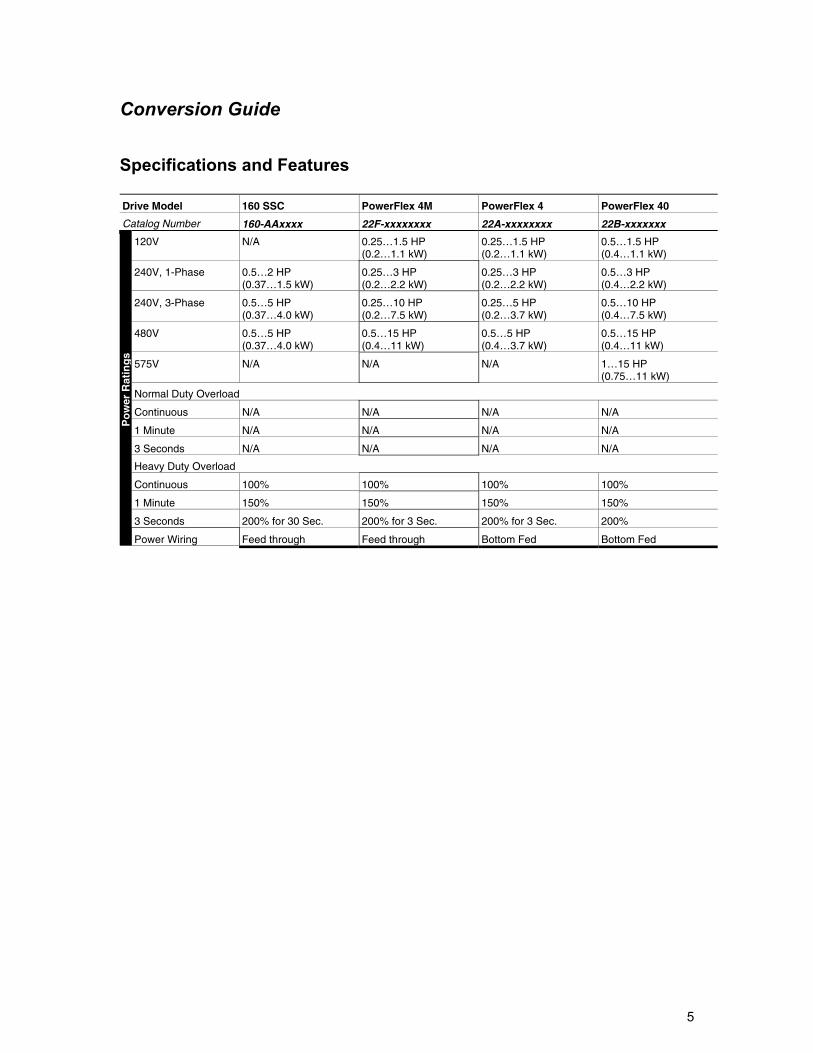
The features of the PowerFlex 4M, 4, and 40 are compared to the 160 SSC. Major differences and in-depth comparison table listed.
Analog Speed Follower
An example of a 160 SSC analog speed follower model is show. Control wiring and parameter comparisons are show for the PowerFlex 4-Class used in this configuration.
Preset
An example of a 160 SSC preset speed model is show. Control wiring and parameter comparisons are show for the PowerFlex 4-Class used in this configuration
DeviceNet
Included in this section are: - Examples of 160 SSC and PowerFlex 4-Class DeviceNet configurations. - Procedures to configure the PowerFlex 4-Class drive. - Procedures configure the DeviceNet scanner are described. - Examples of ControlLogix and SLC PLC logic. - Examples of Explicit Messaging in ControlLogix and SLC.
4
Drive Selection Considerations Selecting a PowerFlex to use as a replacement in a 160 SSC application needs to take into account some of the differences and features between the PowerFlex 4M, 4, and 40. Listed here are some of the major differences in the PowerFlex 4-Class compared to the 160 SSC. The next section has an in-depth comparison of the PowerFlex 4-Class. Feed through wiring The 160 SSC has feed through wiring. The line is connected to the top of the drive and motor is connected to the bottom of the drive. The PowerFlex 4M has feed through wiring. The PowerFlex 4 and 40 terminate the line and motor to the bottom of the drive. DeviceNet The 160 SSC could have an optional 160-DNx DeviceNet communication module. This enables the 160 SSC to be controlled and monitored on DeviceNet. The PowerFlex 40 accepts an optional 22COMM-D DeviceNet communication module mounted directly in the drive. For the PowerFlex 4 and 4M to communicate on DeviceNet, a 22COMM-D module is mounted in an external 22XCOMM module and connected to the drives DSI port. The 160 SSC has configurable Input and Output Assemblies for DeviceNet control of drive. The PowerFlex has fixed Input and Output Assemblies. Logic changes may have to be made to control the PowerFlex in the same manner. Speed Presets The 160 SSC Preset Speed model has eight preset speeds set by three digital inputs. The PowerFlex 40 has eight preset speeds and the PowerFlex 4 and 4M have four preset speeds. Sensorless Vector Control The 160 SSC is a Volts per Hertz drive with adjustments for Boost and Slip Compensation. The PowerFlex 4 and 4M are Volts per Hertz drives as well. The PowerFlex 40 by default is in Sensorless Vector control, which achieves a higher level of torque response and speed accuracy. The PowerFlex 40 can be changed to Volts per Hertz control if need be. Bipolar Speed Reference The 160 SSC can accept a Bipolar (+/-10VDC) speed reference. The direction is set by the polarity of the speed reference. This feature is available on the PowerFlex 40 but not the PowerFlex 4 and 4M. Circuit Protection When selecting a PowerFlex replacement for a 160 SSC, pay attention to the recommendations for fusing and circuit breakers. Protective device sizing may be different between equivalent 160 SSC and PowerFlex drives. More information on the PowerFlex fuse and circuit breaker recommended sizes in the following publications at: http://literature.rockwellautomation.com 22A-UM001 PowerFlex 4 User Manual 22B-UM001 PowerFlex 40 User Manual 22F-UM001 PowerFlex 4M User Manual
5
Conversion Guide
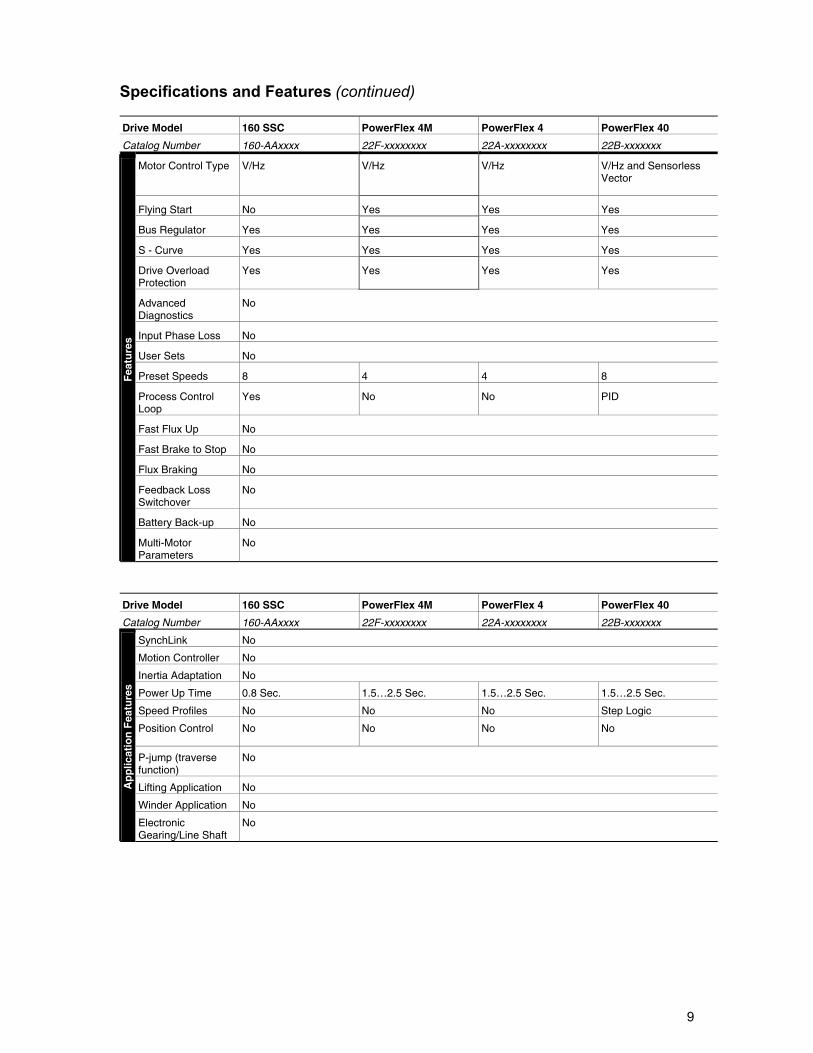
Specifications and Features Drive Model 160 SSC PowerFlex 4M PowerFlex 4 PowerFlex 40
Catalog Number 160-AAxxxx 22F-xxxxxxxx 22A-xxxxxxxx 22B-xxxxxxx
120V N/A 0.25…1.5 HP (0.2…1.1 kW)
0.25…1.5 HP (0.2…1.1 kW)
0.5…1.5 HP (0.4…1.1 kW)
240V, 1-Phase 0.5…2 HP (0.37…1.5 kW)
0.25…3 HP (0.2…2.2 kW)
0.25…3 HP (0.2…2.2 kW)
0.5…3 HP (0.4…2.2 kW)
240V, 3-Phase 0.5…5 HP (0.37…4.0 kW)
0.25…10 HP (0.2…7.5 kW)
0.25…5 HP (0.2…3.7 kW)
0.5…10 HP (0.4…7.5 kW)
480V 0.5…5 HP (0.37…4.0 kW)
0.5…15 HP (0.4…11 kW)
0.5…5 HP (0.4…3.7 kW)
0.5…15 HP (0.4…11 kW)
575V N/A N/A N/A 1…15 HP (0.75…11 kW)
Normal Duty Overload
Continuous N/A N/A N/A N/A
1 Minute N/A N/A N/A N/A
3 Seconds N/A N/A N/A N/A
Heavy Duty Overload
Continuous 100% 100% 100% 100%
1 Minute 150% 150% 150% 150%
3 Seconds 200% for 30 Sec. 200% for 3 Sec. 200% for 3 Sec. 200%
Po
wer
Rat
ing
s
Power Wiring Feed through Feed through Bottom Fed Bottom Fed
6
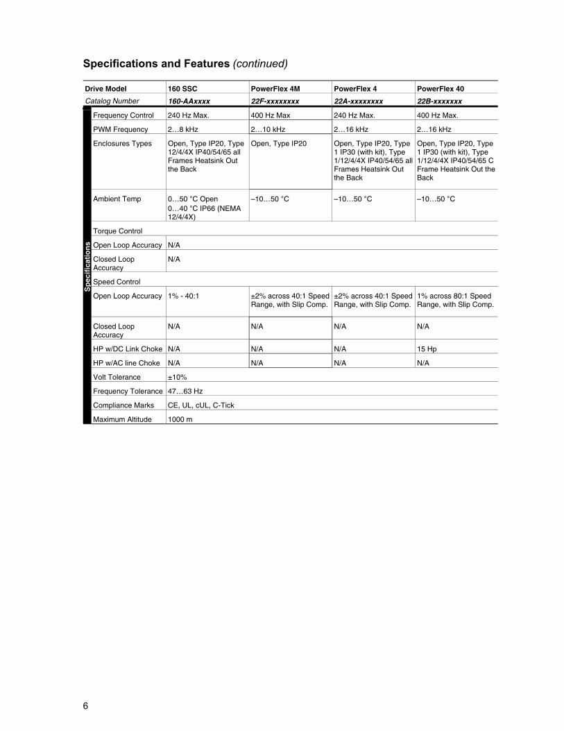
Specifications and Features (continued) Drive Model 160 SSC PowerFlex 4M PowerFlex 4 PowerFlex 40
Catalog Number 160-AAxxxx 22F-xxxxxxxx 22A-xxxxxxxx 22B-xxxxxxx
Frequency Control 240 Hz Max. 400 Hz Max 240 Hz Max. 400 Hz Max.
PWM Frequency 2…8 kHz 2…10 kHz 2…16 kHz 2…16 kHz
Enclosures Types Open, Type IP20, Type 12/4/4X IP40/54/65 all Frames Heatsink Out the Back
Open, Type IP20 Open, Type IP20, Type 1 IP30 (with kit), Type 1/12/4/4X IP40/54/65 all Frames Heatsink Out the Back
Open, Type IP20, Type 1 IP30 (with kit), Type 1/12/4/4X IP40/54/65 C Frame Heatsink Out the Back
Ambient Temp 0…50 °C Open 0…40 °C IP66 (NEMA 12/4/4X)
–10…50 °C –10…50 °C –10…50 °C
Torque Control
Open Loop Accuracy N/A
Closed Loop Accuracy
N/A
Speed Control
Open Loop Accuracy 1% - 40:1 ±2% across 40:1 Speed Range, with Slip Comp.
±2% across 40:1 Speed Range, with Slip Comp.
1% across 80:1 Speed Range, with Slip Comp.
Closed Loop Accuracy
N/A N/A N/A N/A
HP w/DC Link Choke N/A N/A N/A 15 Hp
HP w/AC line Choke N/A N/A N/A N/A
Volt Tolerance ±10%
Frequency Tolerance 47…63 Hz
Compliance Marks CE, UL, cUL, C-Tick
Sp
ecif
icat
ion
s
Maximum Altitude 1000 m
7
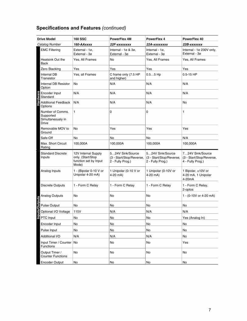
Specifications and Features (continued) Drive Model 160 SSC PowerFlex 4M PowerFlex 4 PowerFlex 40
Catalog Number 160-AAxxxx 22F-xxxxxxxx 22A-xxxxxxxx 22B-xxxxxxx
EMC Filtering External - 1ø, External - 3ø
Internal - 1ø & 3ø, External - 3ø
Internal - 1ø, External - 3ø
Internal - 1ø 230V only, External - 3ø
Heatsink Out the Back
Yes, All Frames No Yes, All Frames Yes, All Frames
Zero Stacking Yes Yes Yes Yes
Internal DB Transistor
Yes, all Frames C frame only (7.5 HP and higher)
0.5…5 Hp 0.5-15 HP
Internal DB Resistor Option
No N/A N/A N/A
Encoder Input Standard
N/A N/A N/A N/A
Additional Feedback Options
N/A N/A N/A No
Number of Comms. Supported Simultaneously in Drive
1 0 0 1
Removable MOV to Ground
No Yes Yes Yes
Safe-Off No No No N/A
Har
dw
are
Max. Short Circuit Rating
100,000A 100,000A 100,000A 100,000A
Standard Discrete Inputs
12V Internal Supply only. (Start/Stop function set by Input Mode)
5…24V Sink/Source (3 - Start/Stop/Reverse, 2 - Fully Prog.)
5…24V Sink/Source (3 - Start/Stop/Reverse, 2 - Fully Prog.)
7…24V Sink/Source (3 - Start/Stop/Reverse, 4 - Fully Prog.)
Analog Inputs 1 - (Bipolar 0-10 V or Unipolar 4-20 mA)
1 Unipolar (0-10 V or 4-20 mA)
1 Unipolar (0-10V or 4-20 mA)
1 Bipolar, ±10V or 4-20 mA, 1 Unipolar 4-20mA
Discrete Outputs 1 - Form C Relay 1 - Form C Relay 1 - Form C Relay 1 - Form C Relay, 2-optos
Analog Outputs No No No 1 - (0-10V or 4-20 mA)
Pulse Output No No No No
Optional I/O Voltage 115V N/A N/A N/A
PTC Input No No No Yes (Analog In)
Encoder Input No No No No
Pulse Input No No No No
Additional I/O N/A N/A N/A No
Input Timer / Counter Functions
No No No Yes
Output Timer / Counter Functions
No No No No
Inp
uts
/Ou
tpu
ts
Encoder Output No No No No
8
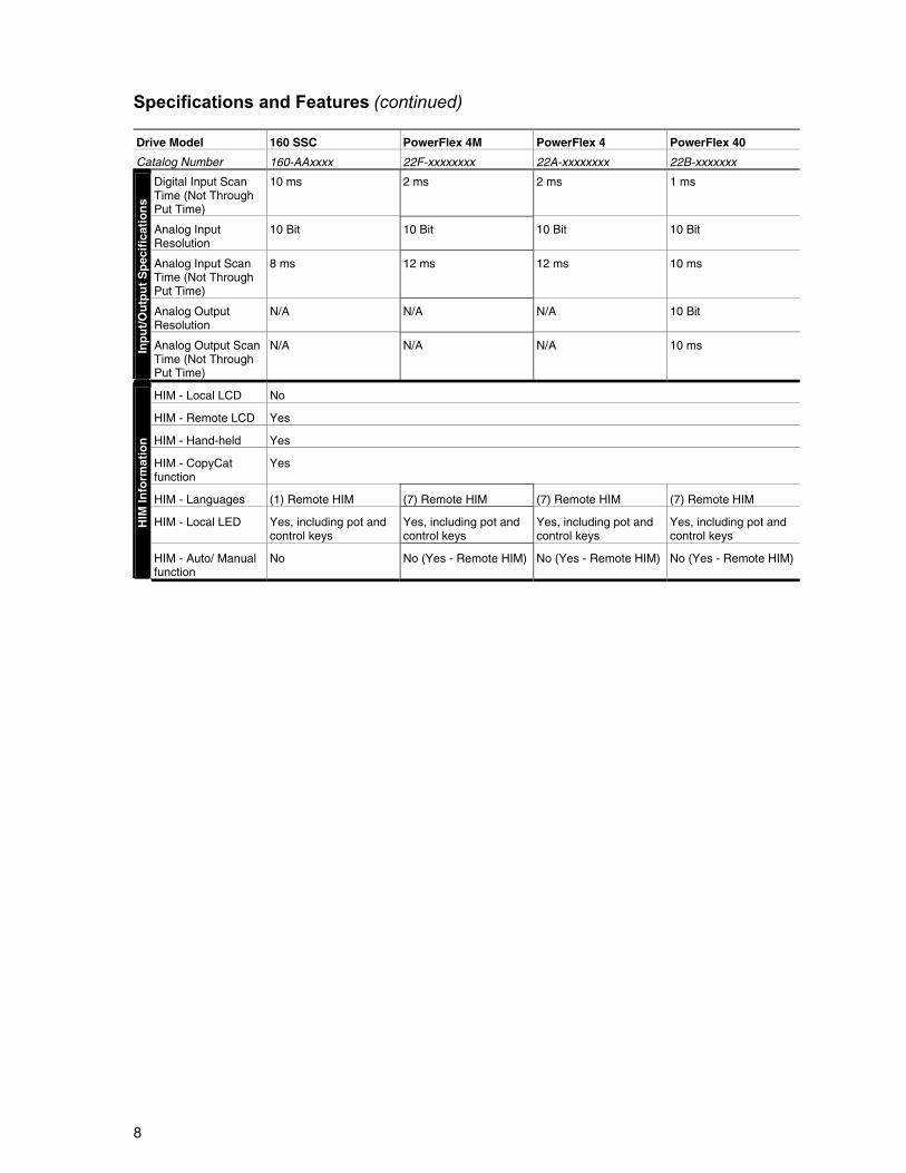
Specifications and Features (continued) Drive Model 160 SSC PowerFlex 4M PowerFlex 4 PowerFlex 40
Catalog Number 160-AAxxxx 22F-xxxxxxxx 22A-xxxxxxxx 22B-xxxxxxx
Digital Input Scan Time (Not Through Put Time)
10 ms 2 ms 2 ms 1 ms
Analog Input Resolution
10 Bit 10 Bit 10 Bit 10 Bit
Analog Input Scan Time (Not Through Put Time)
8 ms 12 ms 12 ms 10 ms
Analog Output Resolution
N/A N/A N/A 10 Bit
Inp
ut/
Ou
tpu
t S
pec
ific
atio
ns
Analog Output Scan Time (Not Through Put Time)
N/A N/A N/A 10 ms
HIM - Local LCD No
HIM - Remote LCD Yes
HIM - Hand-held Yes
HIM - CopyCat function
Yes
HIM - Languages (1) Remote HIM (7) Remote HIM (7) Remote HIM (7) Remote HIM
HIM - Local LED Yes, including pot and control keys
Yes, including pot and control keys
Yes, including pot and control keys
Yes, including pot and control keys
HIM
Info
rmat
ion
HIM - Auto/ Manual function
No No (Yes - Remote HIM) No (Yes - Remote HIM) No (Yes - Remote HIM)
9
Specifications and Features (continued) Drive Model 160 SSC PowerFlex 4M PowerFlex 4 PowerFlex 40
Catalog Number 160-AAxxxx 22F-xxxxxxxx 22A-xxxxxxxx 22B-xxxxxxx
Motor Control Type V/Hz V/Hz V/Hz V/Hz and Sensorless Vector
Flying Start No Yes Yes Yes
Bus Regulator Yes Yes Yes Yes
S - Curve Yes Yes Yes Yes
Drive Overload Protection
Yes Yes Yes Yes
Advanced Diagnostics
No
Input Phase Loss No
User Sets No
Preset Speeds 8 4 4 8
Process Control Loop
Yes No No PID
Fast Flux Up No
Fast Brake to Stop No
Flux Braking No
Feedback Loss Switchover
No
Battery Back-up No
Fea
ture
s
Multi-Motor Parameters
No
Drive Model 160 SSC PowerFlex 4M PowerFlex 4 PowerFlex 40
Catalog Number 160-AAxxxx 22F-xxxxxxxx 22A-xxxxxxxx 22B-xxxxxxx
SynchLink No
Motion Controller No
Inertia Adaptation No
Power Up Time 0.8 Sec. 1.5…2.5 Sec. 1.5…2.5 Sec. 1.5…2.5 Sec.
Speed Profiles No No No Step Logic
Position Control No No No No
P-jump (traverse function)
No
Lifting Application No
Winder Application No
Ap
plic
atio
n F
eatu
res
Electronic Gearing/Line Shaft
No
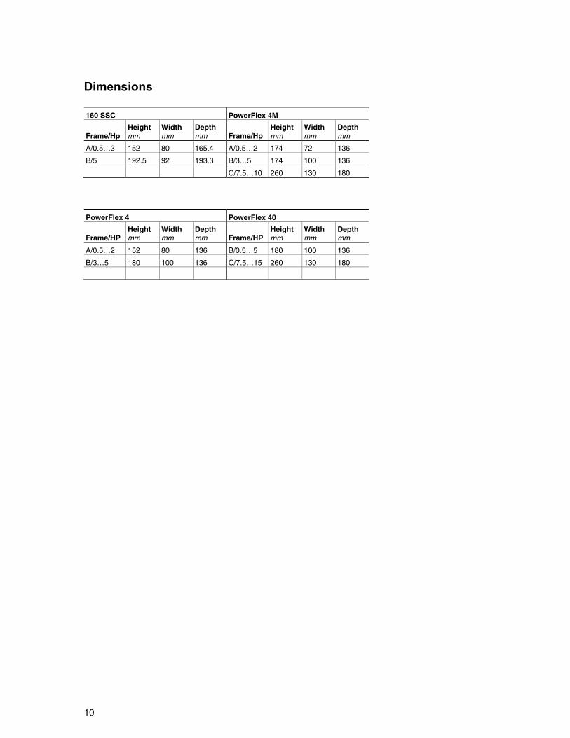
10
Dimensions 160 SSC PowerFlex 4M
Frame/Hp Height mm
Width mm
Depth mm Frame/Hp
Height mm
Width mm
Depth mm
A/0.5…3 152 80 165.4 A/0.5…2 174 72 136
B/5 192.5 92 193.3 B/3…5 174 100 136
C/7.5…10 260 130 180
PowerFlex 4 PowerFlex 40
Frame/HP Height mm
Width mm
Depth mm Frame/HP
Height mm
Width mm
Depth mm
A/0.5…2 152 80 136 B/0.5…5 180 100 136
B/3…5 180 100 136 C/7.5…15 260 130 180
11
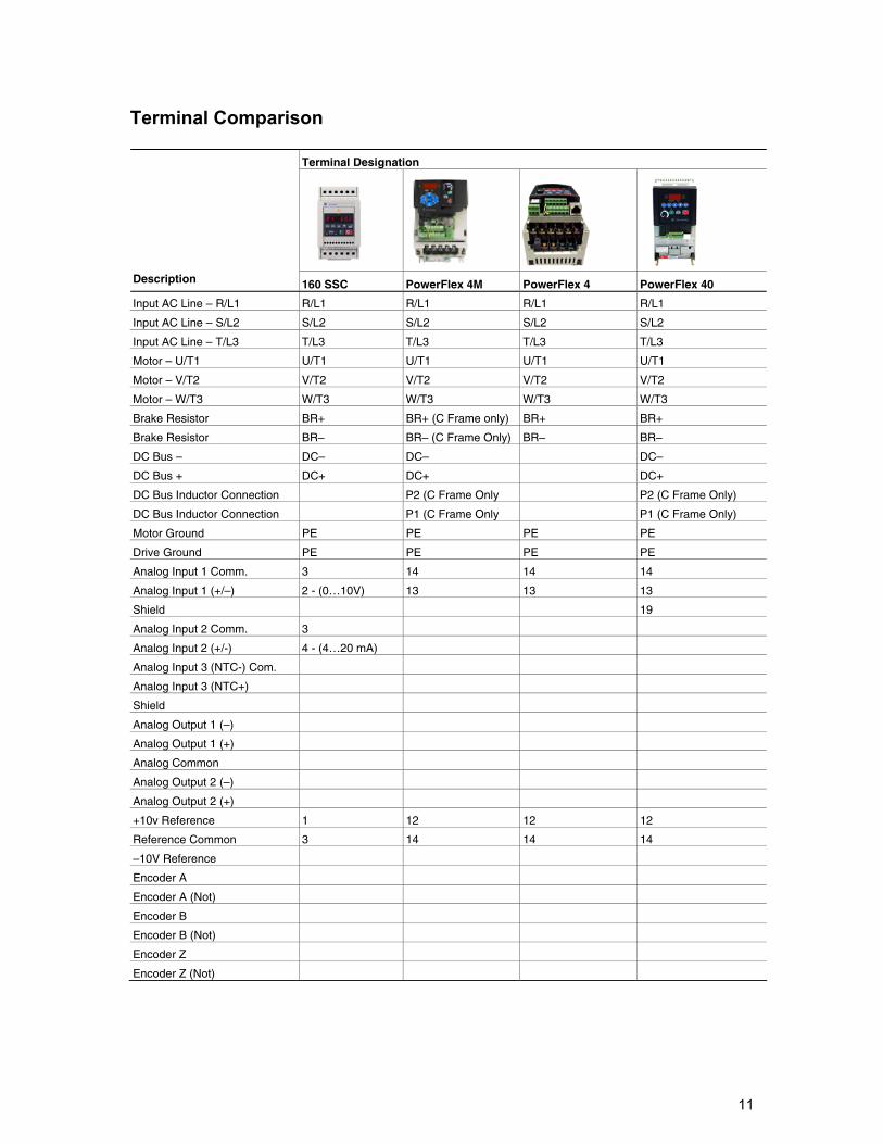
Terminal Comparison
Terminal Designation
Description 160 SSC PowerFlex 4M PowerFlex 4 PowerFlex 40
Input AC Line – R/L1 R/L1 R/L1 R/L1 R/L1
Input AC Line – S/L2 S/L2 S/L2 S/L2 S/L2
Input AC Line – T/L3 T/L3 T/L3 T/L3 T/L3
Motor – U/T1 U/T1 U/T1 U/T1 U/T1
Motor – V/T2 V/T2 V/T2 V/T2 V/T2
Motor – W/T3 W/T3 W/T3 W/T3 W/T3
Brake Resistor BR+ BR+ (C Frame only) BR+ BR+
Brake Resistor BR– BR– (C Frame Only) BR– BR–
DC Bus – DC– DC– DC–
DC Bus + DC+ DC+ DC+
DC Bus Inductor Connection P2 (C Frame Only P2 (C Frame Only)
DC Bus Inductor Connection P1 (C Frame Only P1 (C Frame Only)
Motor Ground PE PE PE PE
Drive Ground PE PE PE PE
Analog Input 1 Comm. 3 14 14 14
Analog Input 1 (+/–) 2 - (0…10V) 13 13 13
Shield 19
Analog Input 2 Comm. 3
Analog Input 2 (+/-) 4 - (4…20 mA)
Analog Input 3 (NTC-) Com.
Analog Input 3 (NTC+)
Shield
Analog Output 1 (–)
Analog Output 1 (+)
Analog Common
Analog Output 2 (–)
Analog Output 2 (+)
+10v Reference 1 12 12 12
Reference Common 3 14 14 14
–10V Reference
Encoder A
Encoder A (Not)
Encoder B
Encoder B (Not)
Encoder Z
Encoder Z (Not)
12
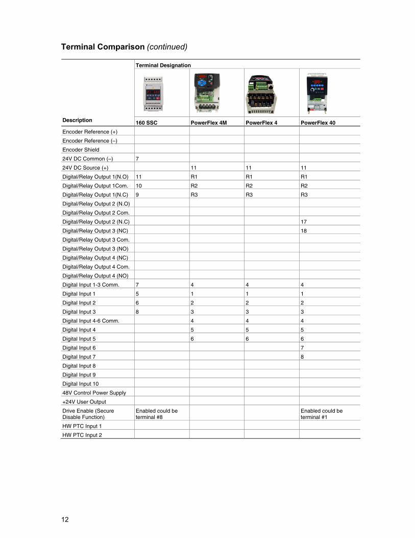
Terminal Comparison (continued)
Terminal Designation
Description 160 SSC PowerFlex 4M PowerFlex 4 PowerFlex 40
Encoder Reference (+)
Encoder Reference (–)
Encoder Shield
24V DC Common (–) 7
24V DC Source (+) 11 11 11
Digital/Relay Output 1(N.O) 11 R1 R1 R1
Digital/Relay Output 1Com. 10 R2 R2 R2
Digital/Relay Output 1(N.C) 9 R3 R3 R3
Digital/Relay Output 2 (N.O)
Digital/Relay Output 2 Com.
Digital/Relay Output 2 (N.C) 17
Digital/Relay Output 3 (NC) 18
Digital/Relay Output 3 Com.
Digital/Relay Output 3 (NO)
Digital/Relay Output 4 (NC)
Digital/Relay Output 4 Com.
Digital/Relay Output 4 (NO)
Digital Input 1-3 Comm. 7 4 4 4
Digital Input 1 5 1 1 1
Digital Input 2 6 2 2 2
Digital Input 3 8 3 3 3
Digital Input 4-6 Comm. 4 4 4
Digital Input 4 5 5 5
Digital Input 5 6 6 6
Digital Input 6 7
Digital Input 7 8
Digital Input 8
Digital Input 9
Digital Input 10
48V Control Power Supply
+24V User Output
Drive Enable (Secure Disable Function)
Enabled could be terminal #8
Enabled could be terminal #1
HW PTC Input 1
HW PTC Input 2
13
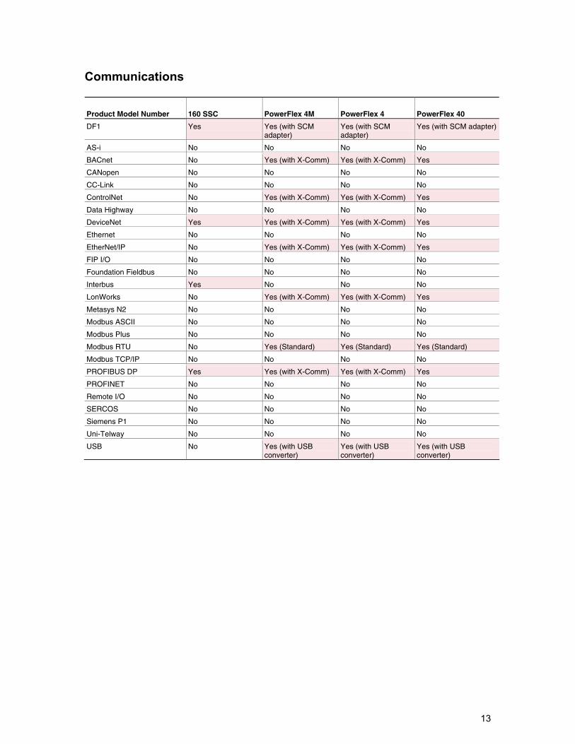
Communications
Product Model Number 160 SSC PowerFlex 4M PowerFlex 4 PowerFlex 40
DF1 Yes Yes (with SCM adapter)
Yes (with SCM adapter)
Yes (with SCM adapter)
AS-i No No No No
BACnet No Yes (with X-Comm) Yes (with X-Comm) Yes
CANopen No No No No
CC-Link No No No No
ControlNet No Yes (with X-Comm) Yes (with X-Comm) Yes
Data Highway No No No No
DeviceNet Yes Yes (with X-Comm) Yes (with X-Comm) Yes
Ethernet No No No No
EtherNet/IP No Yes (with X-Comm) Yes (with X-Comm) Yes
FIP I/O No No No No
Foundation Fieldbus No No No No
Interbus Yes No No No
LonWorks No Yes (with X-Comm) Yes (with X-Comm) Yes
Metasys N2 No No No No
Modbus ASCII No No No No
Modbus Plus No No No No
Modbus RTU No Yes (Standard) Yes (Standard) Yes (Standard)
Modbus TCP/IP No No No No
PROFIBUS DP Yes Yes (with X-Comm) Yes (with X-Comm) Yes
PROFINET No No No No
Remote I/O No No No No
SERCOS No No No No
Siemens P1 No No No No
Uni-Telway No No No No
USB No Yes (with USB converter)
Yes (with USB converter)
Yes (with USB converter)
14
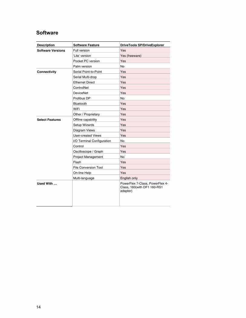
Software Description Software Feature DriveTools SP/DriveExplorer
Full version Yes
'Lite' version Yes (freeware)
Pocket PC version Yes
Software Versions
Palm version No
Serial Point-to-Point Yes
Serial Multi-drop Yes
Ethernet Direct Yes
ControlNet Yes
DeviceNet Yes
Profibus DP No
Bluetooth Yes
WiFi Yes
Connectivity
Other / Proprietary Yes
Offline capability Yes
Setup Wizards Yes
Diagram Views Yes
User-created Views Yes
I/O Terminal Configuration No
Control Yes
Oscilloscope / Graph Yes
Project Management No
Flash Yes
File Conversion Tool Yes
On-line Help Yes
Select Features
Multi-language English only
Used With … PowerFlex 7-Class, PowerFlex 4- Class, 160(with DF1 160-RS1 adapter)
15
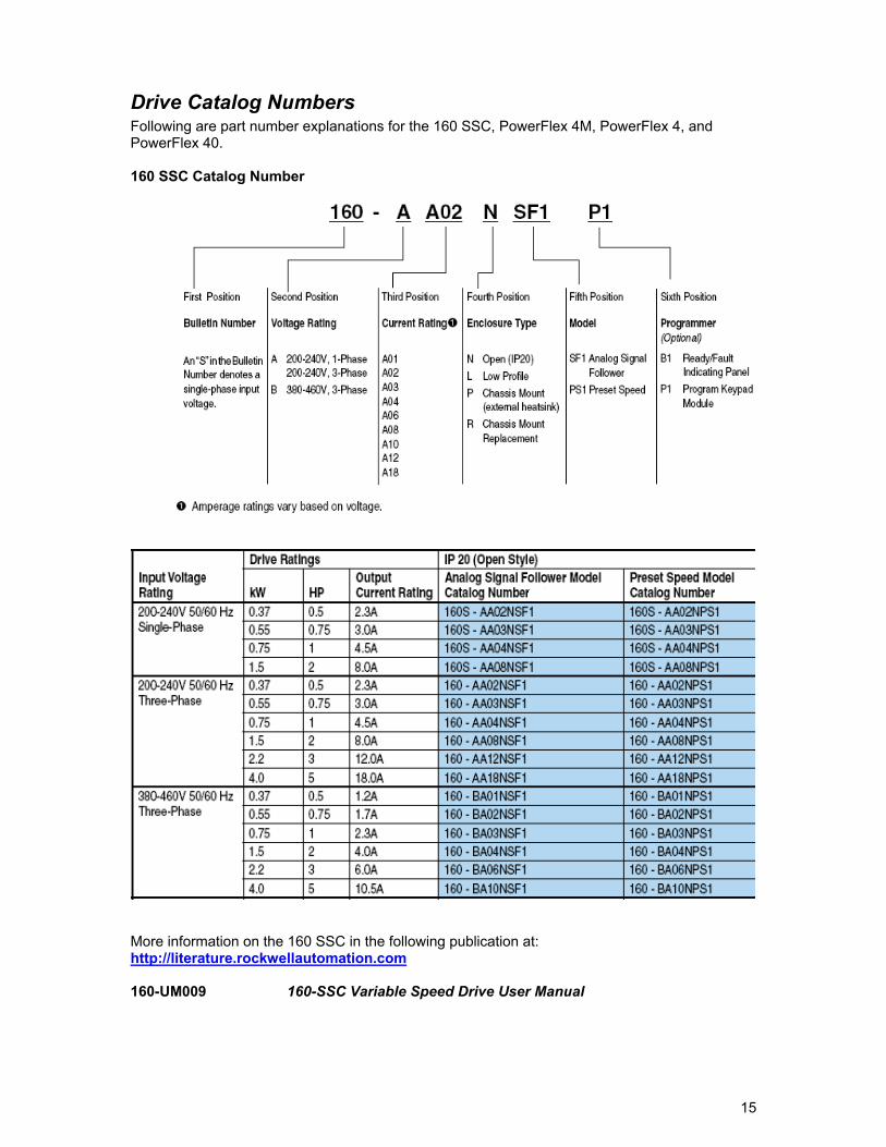
Drive Catalog Numbers Following are part number explanations for the 160 SSC, PowerFlex 4M, PowerFlex 4, and PowerFlex 40. 160 SSC Catalog Number
More information on the 160 SSC in the following publication at: http://literature.rockwellautomation.com 160-UM009 160-SSC Variable Speed Drive User Manual

16
PowerFlex 4 Catalog Number
More information on the PowerFlex 4 in the following publication at: http://literature.rockwellautomation.com 22A-UM001 PowerFlex 4 User Manual
17
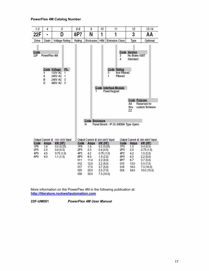
PowerFlex 4M Catalog Number
More information on the PowerFlex 4M in the following publication at: http://literature.rockwellautomation.com 22F-UM001 PowerFlex 4M User Manual
18
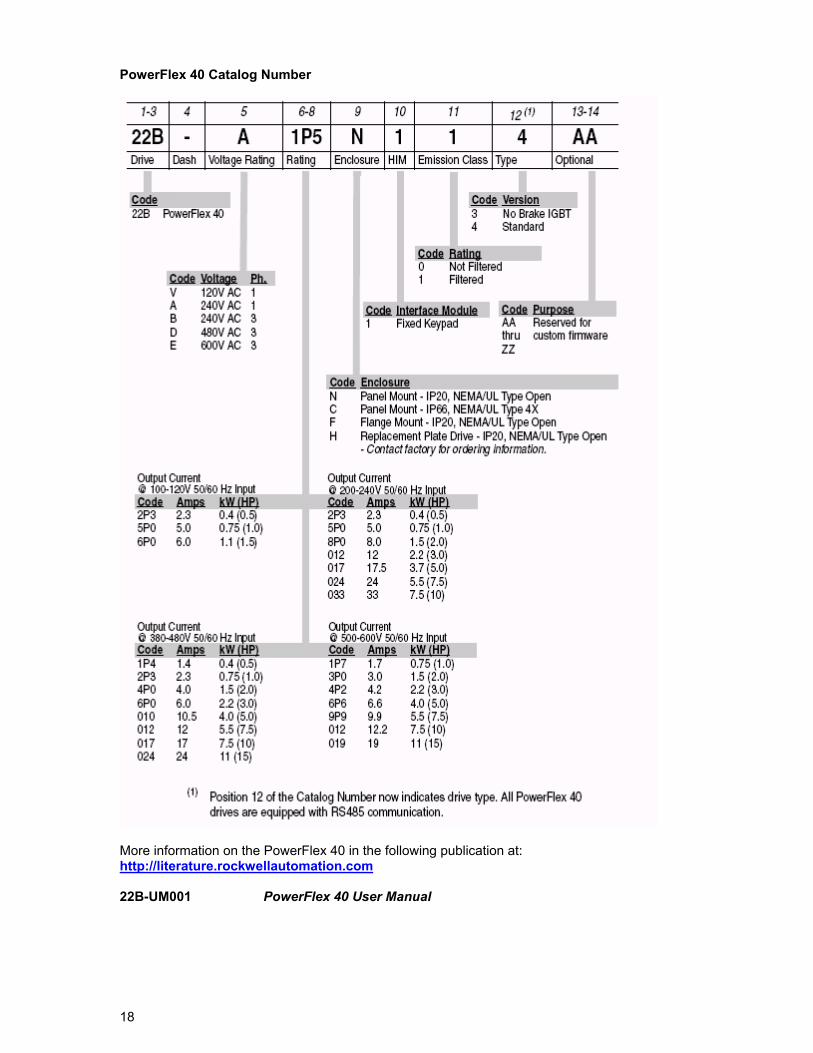
PowerFlex 40 Catalog Number
More information on the PowerFlex 40 in the following publication at: http://literature.rockwellautomation.com 22B-UM001 PowerFlex 40 User Manual
19
Drive Configuration The 160 SSC drive will be an Analog Speed Follower or a Preset Speed module and possibly have a DN2 DeviceNet option module. Because of this, the following examples put the 160 SSC to PowerFlex conversions into three broad categories: Analog Speed Follower Preset Speed DeviceNet The remainder of this document is broken into these three sections.
General Notes The points apply to the PowerFlex drive whether it’s being used as an Analog Speed Follower, Preset Speed, or DeviceNet
SNK/SRC DIP Switch The PowerFlex digital inputs can operate in Sink or Source. To replicate 160 SSC functionality, the SNK/SRC DIP Switch is set to SRC so digital devices are applying a +24VDC to inputs. PowerFlex +24VDC power The PowerFlex drive digital I/O has the ability to use internal or external +24VDC supply. To replicate the wiring of the 160 SSC, the wiring diagrams will show the PowerFlex drive using internal +24VDC supply.
Motor Rotation The output phasing of a 160 SSC series A and B drive is different than the output phasing of a 160 SSC series C and PowerFlex. Replacing a 160 SSC series A or B with a PowerFlex using the same U, V, and W (T1, T2, and T3) connections will reverse the motor rotation. To keep the same direction of rotation, switch any 2 of the output wires connected to U, V, or W (T1, T2, or T3) to the motor.
20
Analog Speed Follower The 160 SSC Analog Speed Follower model accepts a speed reference from a potentiometer, +/-10VDC source, 0-10VDC source, or 4-20 mA source. The 160 SSC can be configured to accept various methods of Start/Stop/Direction control. Three examples show the 160 SSC configured to use different speed reference inputs and Start/Stop/Direction control and equivalent PowerFlex configurations.
21
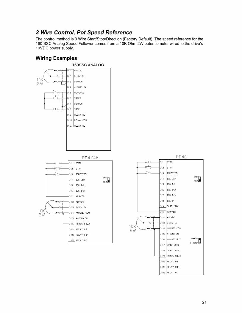
3 Wire Control, Pot Speed Reference The control method is 3 Wire Start/Stop/Direction (Factory Default). The speed reference for the 160 SSC Analog Speed Follower comes from a 10K Ohm 2W potentiometer wired to the drive’s 10VDC power supply.
Wiring Examples
22
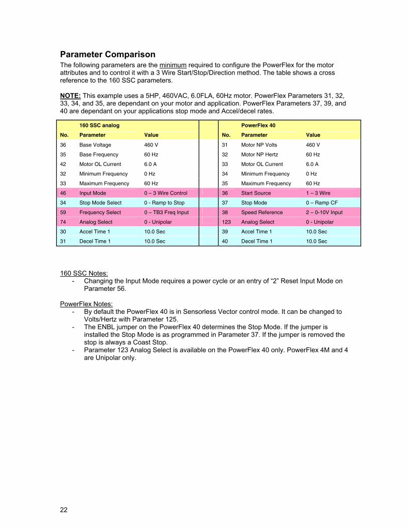
Parameter Comparison The following parameters are the minimum required to configure the PowerFlex for the motor attributes and to control it with a 3 Wire Start/Stop/Direction method. The table shows a cross reference to the 160 SSC parameters. NOTE: This example uses a 5HP, 460VAC, 6.0FLA, 60Hz motor. PowerFlex Parameters 31, 32, 33, 34, and 35, are dependant on your motor and application. PowerFlex Parameters 37, 39, and 40 are dependant on your applications stop mode and Accel/decel rates.
160 SSC Notes:
- Changing the Input Mode requires a power cycle or an entry of “2” Reset Input Mode on Parameter 56.
PowerFlex Notes:
- By default the PowerFlex 40 is in Sensorless Vector control mode. It can be changed to Volts/Hertz with Parameter 125.
- The ENBL jumper on the PowerFlex 40 determines the Stop Mode. If the jumper is installed the Stop Mode is as programmed in Parameter 37. If the jumper is removed the stop is always a Coast Stop.
- Parameter 123 Analog Select is available on the PowerFlex 40 only. PowerFlex 4M and 4 are Unipolar only.
160 SSC analog PowerFlex 40
No. Parameter Value No. Parameter Value
36 Base Voltage 460 V 31 Motor NP Volts 460 V
35 Base Frequency 60 Hz 32 Motor NP Hertz 60 Hz
42 Motor OL Current 6.0 A 33 Motor OL Current 6.0 A
32 Minimum Frequency 0 Hz 34 Minimum Frequency 0 Hz
33 Maximum Frequency 60 Hz 35 Maximum Frequency 60 Hz
46 Input Mode 0 – 3 Wire Control 36 Start Source 1 – 3 Wire
34 Stop Mode Select 0 - Ramp to Stop 37 Stop Mode 0 – Ramp CF
59 Frequency Select 0 – TB3 Freq Input 38 Speed Reference 2 – 0-10V Input
74 Analog Select 0 - Unipolar 123 Analog Select 0 - Unipolar
30 Accel Time 1 10.0 Sec 39 Accel Time 1 10.0 Sec
31 Decel Time 1 10.0 Sec 40 Decel Time 1 10.0 Sec
23
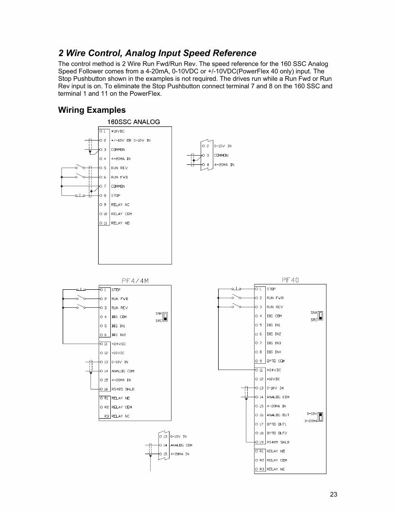
2 Wire Control, Analog Input Speed Reference The control method is 2 Wire Run Fwd/Run Rev. The speed reference for the 160 SSC Analog Speed Follower comes from a 4-20mA, 0-10VDC or +/-10VDC(PowerFlex 40 only) input. The Stop Pushbutton shown in the examples is not required. The drives run while a Run Fwd or Run Rev input is on. To eliminate the Stop Pushbutton connect terminal 7 and 8 on the 160 SSC and terminal 1 and 11 on the PowerFlex.
Wiring Examples
24
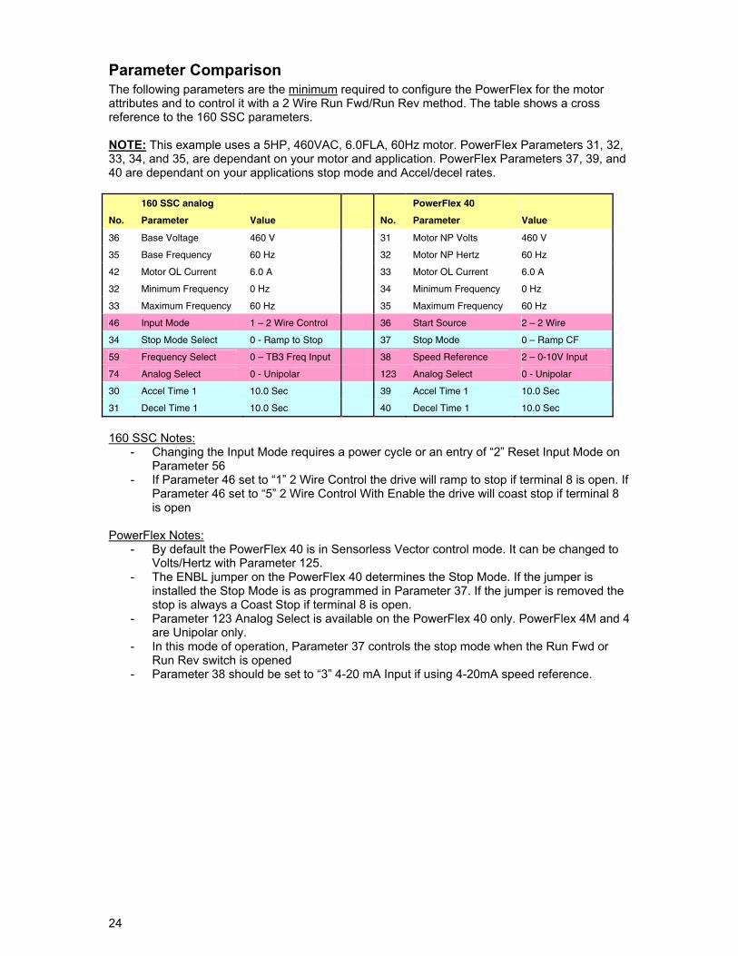
Parameter Comparison The following parameters are the minimum required to configure the PowerFlex for the motor attributes and to control it with a 2 Wire Run Fwd/Run Rev method. The table shows a cross reference to the 160 SSC parameters. NOTE: This example uses a 5HP, 460VAC, 6.0FLA, 60Hz motor. PowerFlex Parameters 31, 32, 33, 34, and 35, are dependant on your motor and application. PowerFlex Parameters 37, 39, and 40 are dependant on your applications stop mode and Accel/decel rates. 160 SSC analog PowerFlex 40
No. Parameter Value No. Parameter Value
36 Base Voltage 460 V 31 Motor NP Volts 460 V
35 Base Frequency 60 Hz 32 Motor NP Hertz 60 Hz
42 Motor OL Current 6.0 A 33 Motor OL Current 6.0 A
32 Minimum Frequency 0 Hz 34 Minimum Frequency 0 Hz
33 Maximum Frequency 60 Hz 35 Maximum Frequency 60 Hz
46 Input Mode 1 – 2 Wire Control 36 Start Source 2 – 2 Wire
34 Stop Mode Select 0 - Ramp to Stop 37 Stop Mode 0 – Ramp CF
59 Frequency Select 0 – TB3 Freq Input 38 Speed Reference 2 – 0-10V Input
74 Analog Select 0 - Unipolar 123 Analog Select 0 - Unipolar
30 Accel Time 1 10.0 Sec 39 Accel Time 1 10.0 Sec
31 Decel Time 1 10.0 Sec 40 Decel Time 1 10.0 Sec
160 SSC Notes:
- Changing the Input Mode requires a power cycle or an entry of “2” Reset Input Mode on Parameter 56
- If Parameter 46 set to “1” 2 Wire Control the drive will ramp to stop if terminal 8 is open. If Parameter 46 set to “5” 2 Wire Control With Enable the drive will coast stop if terminal 8 is open
PowerFlex Notes:
- By default the PowerFlex 40 is in Sensorless Vector control mode. It can be changed to Volts/Hertz with Parameter 125.
- The ENBL jumper on the PowerFlex 40 determines the Stop Mode. If the jumper is installed the Stop Mode is as programmed in Parameter 37. If the jumper is removed the stop is always a Coast Stop if terminal 8 is open.
- Parameter 123 Analog Select is available on the PowerFlex 40 only. PowerFlex 4M and 4 are Unipolar only.
- In this mode of operation, Parameter 37 controls the stop mode when the Run Fwd or Run Rev switch is opened
- Parameter 38 should be set to “3” 4-20 mA Input if using 4-20mA speed reference.
25
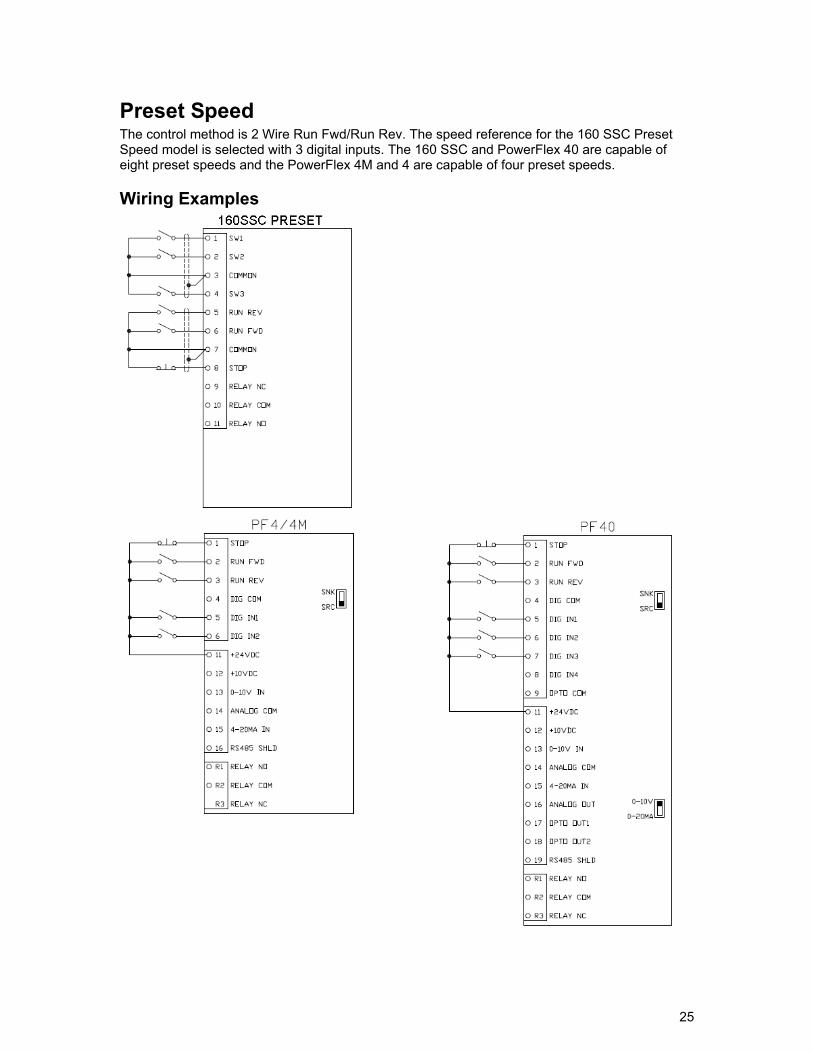
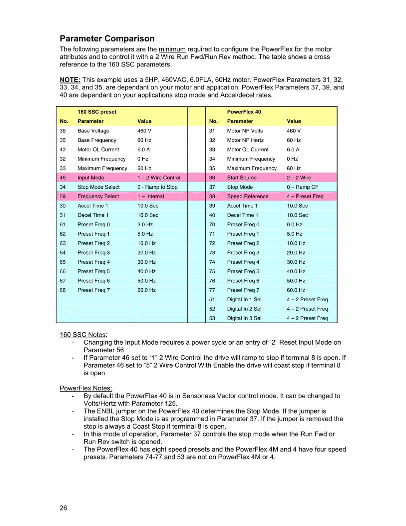
Preset Speed The control method is 2 Wire Run Fwd/Run Rev. The speed reference for the 160 SSC Preset Speed model is selected with 3 digital inputs. The 160 SSC and PowerFlex 40 are capable of eight preset speeds and the PowerFlex 4M and 4 are capable of four preset speeds.
Wiring Examples
26
Parameter Comparison The following parameters are the minimum required to configure the PowerFlex for the motor attributes and to control it with a 2 Wire Run Fwd/Run Rev method. The table shows a cross reference to the 160 SSC parameters. NOTE: This example uses a 5HP, 460VAC, 6.0FLA, 60Hz motor. PowerFlex Parameters 31, 32, 33, 34, and 35, are dependant on your motor and application. PowerFlex Parameters 37, 39, and 40 are dependant on your applications stop mode and Accel/decel rates. 160 SSC preset PowerFlex 40
No. Parameter Value No. Parameter Value
36 Base Voltage 460 V 31 Motor NP Volts 460 V
35 Base Frequency 60 Hz 32 Motor NP Hertz 60 Hz
42 Motor OL Current 6.0 A 33 Motor OL Current 6.0 A
32 Minimum Frequency 0 Hz 34 Minimum Frequency 0 Hz
33 Maximum Frequency 60 Hz 35 Maximum Frequency 60 Hz
46 Input Mode 1 – 2 Wire Control 36 Start Source 2 – 2 Wire
34 Stop Mode Select 0 - Ramp to Stop 37 Stop Mode 0 – Ramp CF
59 Frequency Select 1 – Internal 38 Speed Reference 4 – Preset Freq
30 Accel Time 1 10.0 Sec 39 Accel Time 1 10.0 Sec
31 Decel Time 1 10.0 Sec 40 Decel Time 1 10.0 Sec
61 Preset Freq 0 3.0 Hz 70 Preset Freq 0 0.0 Hz
62 Preset Freq 1 5.0 Hz 71 Preset Freq 1 5.0 Hz
63 Preset Freq 2 10.0 Hz 72 Preset Freq 2 10.0 Hz
64 Preset Freq 3 20.0 Hz 73 Preset Freq 3 20.0 Hz
65 Preset Freq 4 30.0 Hz 74 Preset Freq 4 30.0 Hz
66 Preset Freq 5 40.0 Hz 75 Preset Freq 5 40.0 Hz
67 Preset Freq 6 50.0 Hz 76 Preset Freq 6 50.0 Hz
68 Preset Freq 7 60.0 Hz 77 Preset Freq 7 60.0 Hz
51 Digital In 1 Sel 4 – 2 Preset Freq
52 Digital In 2 Sel 4 – 2 Preset Freq
53 Digital In 3 Sel 4 – 2 Preset Freq
160 SSC Notes:
- Changing the Input Mode requires a power cycle or an entry of “2” Reset Input Mode on Parameter 56
- If Parameter 46 set to “1” 2 Wire Control the drive will ramp to stop if terminal 8 is open. If Parameter 46 set to “5” 2 Wire Control With Enable the drive will coast stop if terminal 8 is open
PowerFlex Notes:
- By default the PowerFlex 40 is in Sensorless Vector control mode. It can be changed to Volts/Hertz with Parameter 125.
- The ENBL jumper on the PowerFlex 40 determines the Stop Mode. If the jumper is installed the Stop Mode is as programmed in Parameter 37. If the jumper is removed the stop is always a Coast Stop if terminal 8 is open.
- In this mode of operation, Parameter 37 controls the stop mode when the Run Fwd or Run Rev switch is opened.
- The PowerFlex 40 has eight speed presets and the PowerFlex 4M and 4 have four speed presets. Parameters 74-77 and 53 are not on PowerFlex 4M or 4.
27
DeviceNet
General A 160 SSC with a DN2 DeviceNet option can be replaced with a PowerFlex 4/4M or PowerFlex 40 Drive. The PowerFlex 4/4M drive requires a 22-XCOMM base and a 22-COMM-D communication adapter to connect the DSI port to DeviceNet. The PowerFlex 40 drive requires a 22-COMM-D communication adapter and adapter cover (22B-CCB or 22B-CCC) to communicate on DeviceNet. The intent of the following procedure is to “Replace” the 160 SSC with a new PowerFlex drive. The new PowerFlex drive will occupy the 160 SSC’s address on DeviceNet, Input/Output space in the DeviceNet scanner, and use the control logic in the PLC. The following are the steps to replace a 160 SSC with a PowerFlex.
• Save existing network configuration. Save the network prior to replacing the 160 SSC. Print a report for reference. The network configuration containing the 160 SSC needs to be referenced for PowerFlex drive and Scanner configuration.
• Install and configure new PowerFlex drive. Edit the PowerFlex drive parameters for
motor size and control over DeviceNet.
• Configure DeviceNet Scanner. Use existing 160 SSC Input/Output mapping in Scanner for PowerFlex Input/Output.
• Edit PLC logic. Control logic for the 160 SSC needs to be edited because the Command
and Status for the PowerFlex may be different. Examples for ControlLogix, and SLC are given.
Software Versions RSNetworx for DeviceNet is used to configure the DeviceNet and the PowerFlex drive. RSNetworx v7.00 or higher is recommended. RSNetworx v 9.00 was used for this document.
28
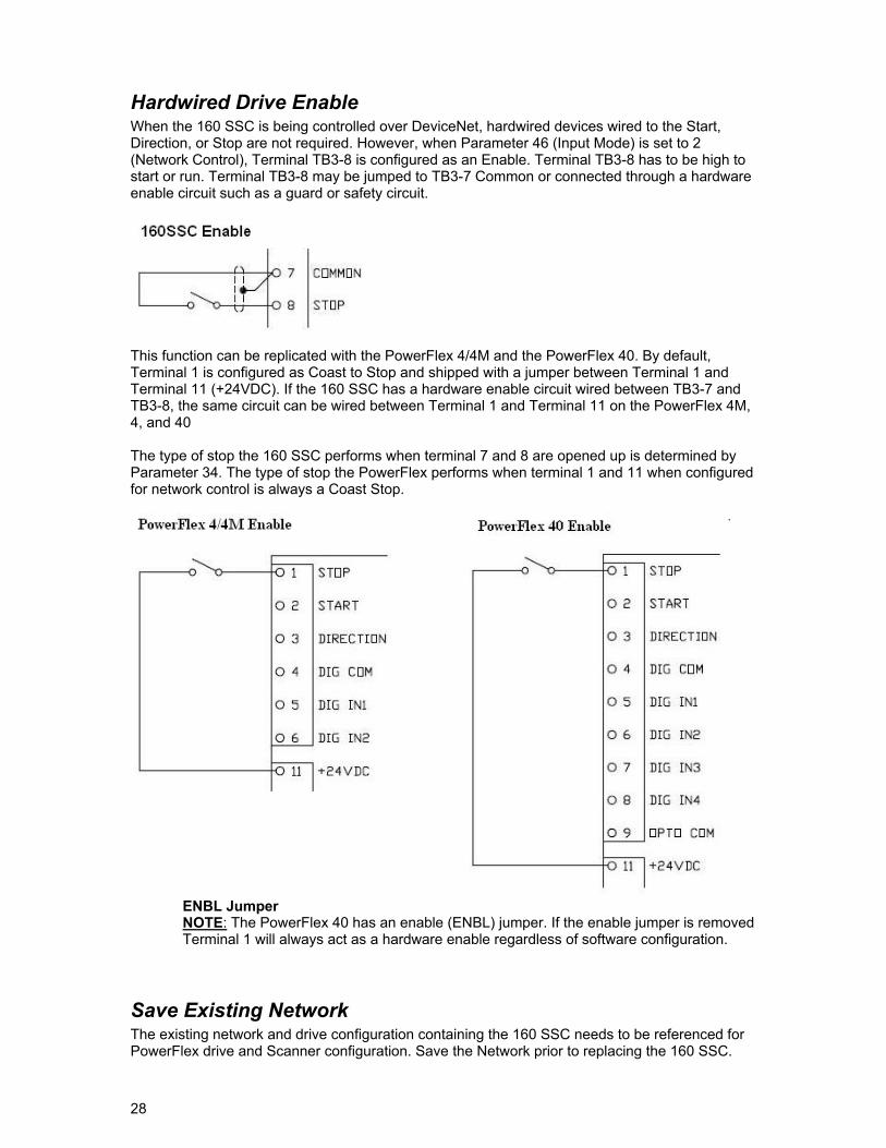
Hardwired Drive Enable When the 160 SSC is being controlled over DeviceNet, hardwired devices wired to the Start, Direction, or Stop are not required. However, when Parameter 46 (Input Mode) is set to 2 (Network Control), Terminal TB3-8 is configured as an Enable. Terminal TB3-8 has to be high to start or run. Terminal TB3-8 may be jumped to TB3-7 Common or connected through a hardware enable circuit such as a guard or safety circuit.
This function can be replicated with the PowerFlex 4/4M and the PowerFlex 40. By default, Terminal 1 is configured as Coast to Stop and shipped with a jumper between Terminal 1 and Terminal 11 (+24VDC). If the 160 SSC has a hardware enable circuit wired between TB3-7 and TB3-8, the same circuit can be wired between Terminal 1 and Terminal 11 on the PowerFlex 4M, 4, and 40 The type of stop the 160 SSC performs when terminal 7 and 8 are opened up is determined by Parameter 34. The type of stop the PowerFlex performs when terminal 1 and 11 when configured for network control is always a Coast Stop.
ENBL Jumper NOTE: The PowerFlex 40 has an enable (ENBL) jumper. If the enable jumper is removed Terminal 1 will always act as a hardware enable regardless of software configuration.
Save Existing Network The existing network and drive configuration containing the 160 SSC needs to be referenced for PowerFlex drive and Scanner configuration. Save the Network prior to replacing the 160 SSC.
29
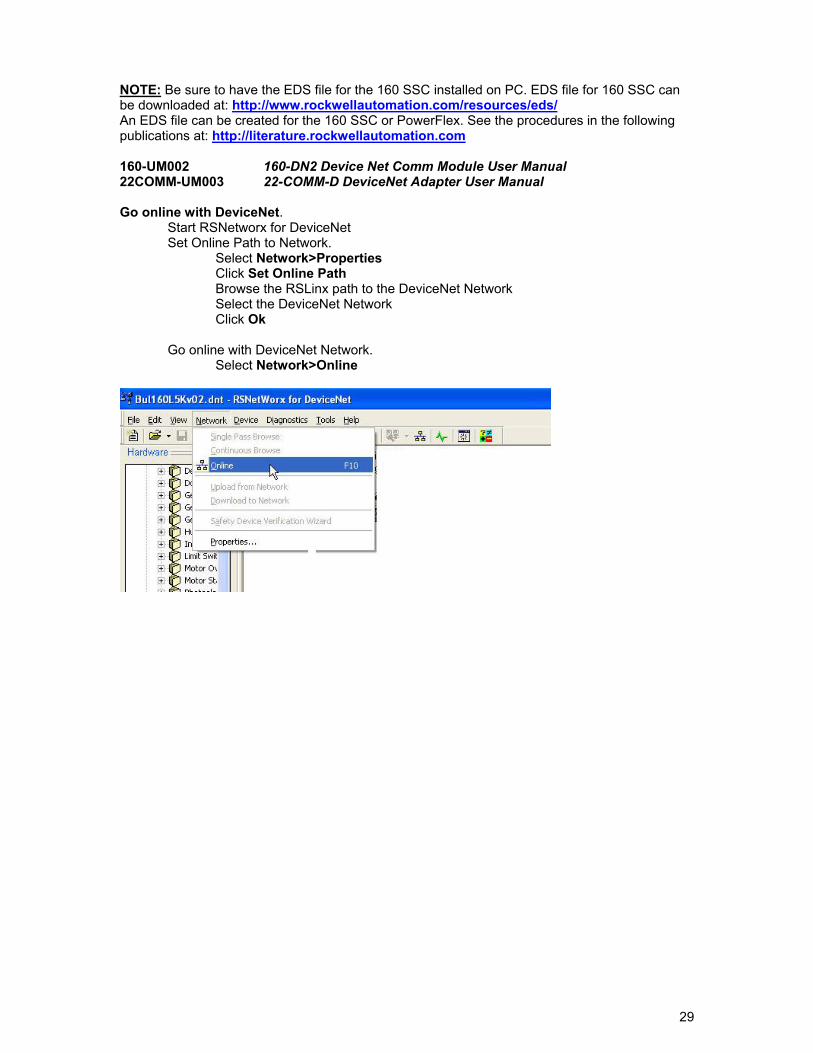
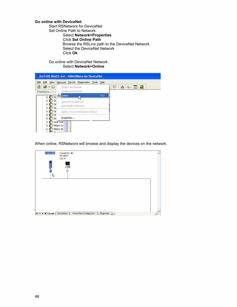
NOTE: Be sure to have the EDS file for the 160 SSC installed on PC. EDS file for 160 SSC can be downloaded at: http://www.rockwellautomation.com/resources/eds/ An EDS file can be created for the 160 SSC or PowerFlex. See the procedures in the following publications at: http://literature.rockwellautomation.com 160-UM002 160-DN2 Device Net Comm Module User Manual 22COMM-UM003 22-COMM-D DeviceNet Adapter User Manual Go online with DeviceNet.
Start RSNetworx for DeviceNet Set Online Path to Network. Select Network>Properties Click Set Online Path Browse the RSLinx path to the DeviceNet Network Select the DeviceNet Network Click Ok Go online with DeviceNet Network. Select Network>Online
30
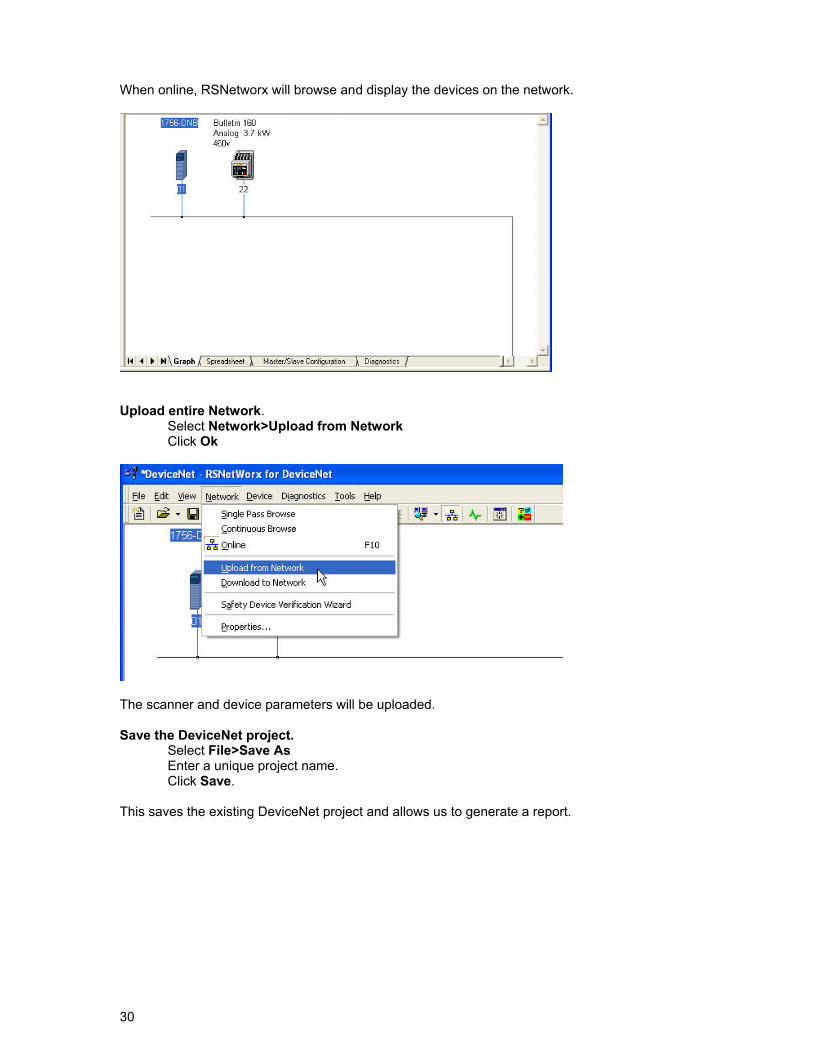
When online, RSNetworx will browse and display the devices on the network.
Upload entire Network.
Select Network>Upload from Network Click Ok
The scanner and device parameters will be uploaded. Save the DeviceNet project.
Select File>Save As Enter a unique project name. Click Save.
This saves the existing DeviceNet project and allows us to generate a report.
31
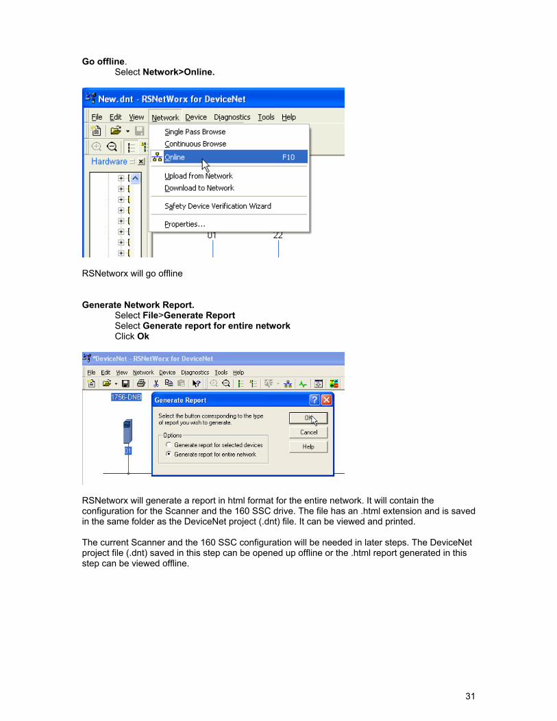
Go offline. Select Network>Online.
RSNetworx will go offline Generate Network Report.
Select File>Generate Report Select Generate report for entire network Click Ok
RSNetworx will generate a report in html format for the entire network. It will contain the configuration for the Scanner and the 160 SSC drive. The file has an .html extension and is saved in the same folder as the DeviceNet project (.dnt) file. It can be viewed and printed. The current Scanner and the 160 SSC configuration will be needed in later steps. The DeviceNet project file (.dnt) saved in this step can be opened up offline or the .html report generated in this step can be viewed offline.
32
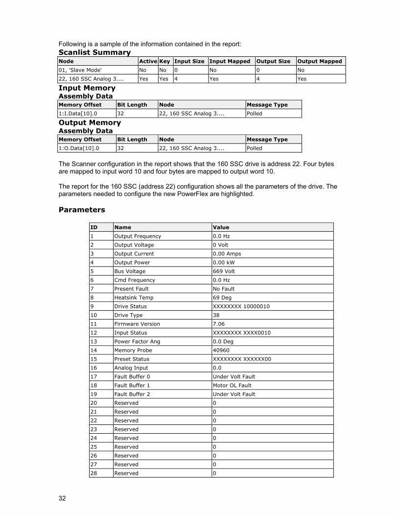
Following is a sample of the information contained in the report: Scanlist Summary Node Active Key Input Size Input Mapped Output Size Output Mapped
01, 'Slave Mode' No No 0 No 0 No
22, 160 SSC Analog 3.... Yes Yes 4 Yes 4 Yes
Input Memory Assembly Data Memory Offset Bit Length Node Message Type
1:I.Data[10].0 32 22, 160 SSC Analog 3.... Polled
Output Memory Assembly Data Memory Offset Bit Length Node Message Type
1:O.Data[10].0 32 22, 160 SSC Analog 3.... Polled
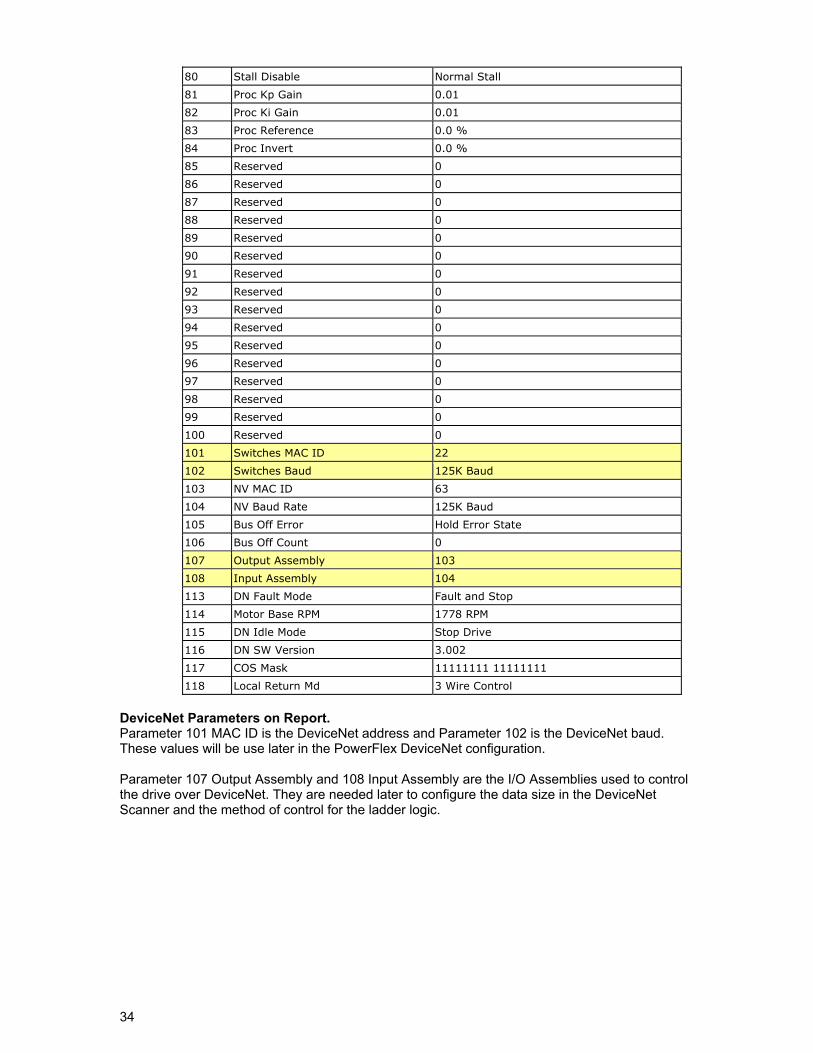
The Scanner configuration in the report shows that the 160 SSC drive is address 22. Four bytes are mapped to input word 10 and four bytes are mapped to output word 10. The report for the 160 SSC (address 22) configuration shows all the parameters of the drive. The parameters needed to configure the new PowerFlex are highlighted. Parameters
ID Name Value
1 Output Frequency 0.0 Hz
2 Output Voltage 0 Volt
3 Output Current 0.00 Amps
4 Output Power 0.00 kW
5 Bus Voltage 669 Volt
6 Cmd Frequency 0.0 Hz
7 Present Fault No Fault
8 Heatsink Temp 69 Deg
9 Drive Status XXXXXXXX 10000010
10 Drive Type 38
11 Firmware Version 7.06
12 Input Status XXXXXXXX XXXX0010
13 Power Factor Ang 0.0 Deg
14 Memory Probe 40960
15 Preset Status XXXXXXXX XXXXXX00
16 Analog Input 0.0
17 Fault Buffer 0 Under Volt Fault
18 Fault Buffer 1 Motor OL Fault
19 Fault Buffer 2 Under Volt Fault
20 Reserved 0
21 Reserved 0
22 Reserved 0
23 Reserved 0
24 Reserved 0
25 Reserved 0
26 Reserved 0
27 Reserved 0
28 Reserved 0
33
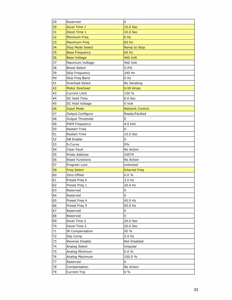
29 Reserved 0
30 Accel Time 1 10.0 Sec
31 Decel Time 1 10.0 Sec
32 Minimum Freq 0 Hz
33 Maximum Freq 60 Hz
34 Stop Mode Select Ramp to Stop
35 Base Frequency 60 Hz
36 Base Voltage 460 Volt
37 Maximum Voltage 460 Volt
38 Boost Select 5.0%
39 Skip Frequency 240 Hz
40 Skip Freq Band 0 Hz
41 Overload Select No Derating
42 Motor Overload 6.00 Amps
43 Current Limit 150 %
44 DC Hold Time 0.0 Sec
45 DC Hold Voltage 0 Volt
46 Input Mode Network Control
47 Output Configure Ready/Faulted
48 Output Threshold 0
49 PWM Frequency 4.0 kHz
50 Restart Tries 0
51 Restart Time 10.0 Sec
52 DB Enable 0
53 S-Curve 0%
54 Clear Fault No Action
55 Probe Address 24574
56 Reset Functions No Action
57 Program Lock Unlocked
59 Freq Select Internal Freq
60 Zero Offset 0.0 %
61 Preset Freq 0 3.0 Hz
62 Preset Freq 1 20.0 Hz
63 Reserved 0
64 Reserved 0
65 Preset Freq 4 45.0 Hz
66 Preset Freq 5 50.0 Hz
67 Reserved 0
68 Reserved 0
69 Accel Time 2 20.0 Sec
70 Decel Time 2 20.0 Sec
71 IR Compensation 50 %
72 Slip Comp 2.0 Hz
73 Reverse Disable Not Disabled
74 Analog Select Unipolar
75 Analog Minimum 0.0 %
76 Analog Maximum 100.0 %
77 Reserved 0
78 Compensation No Action
79 Current Trip 0 %
34
80 Stall Disable Normal Stall
81 Proc Kp Gain 0.01
82 Proc Ki Gain 0.01
83 Proc Reference 0.0 %
84 Proc Invert 0.0 %
85 Reserved 0
86 Reserved 0
87 Reserved 0
88 Reserved 0
89 Reserved 0
90 Reserved 0
91 Reserved 0
92 Reserved 0
93 Reserved 0
94 Reserved 0
95 Reserved 0
96 Reserved 0
97 Reserved 0
98 Reserved 0
99 Reserved 0
100 Reserved 0
101 Switches MAC ID 22
102 Switches Baud 125K Baud
103 NV MAC ID 63
104 NV Baud Rate 125K Baud
105 Bus Off Error Hold Error State
106 Bus Off Count 0
107 Output Assembly 103
108 Input Assembly 104
113 DN Fault Mode Fault and Stop
114 Motor Base RPM 1778 RPM
115 DN Idle Mode Stop Drive
116 DN SW Version 3.002
117 COS Mask 11111111 11111111
118 Local Return Md 3 Wire Control
DeviceNet Parameters on Report. Parameter 101 MAC ID is the DeviceNet address and Parameter 102 is the DeviceNet baud. These values will be use later in the PowerFlex DeviceNet configuration. Parameter 107 Output Assembly and 108 Input Assembly are the I/O Assemblies used to control the drive over DeviceNet. They are needed later to configure the data size in the DeviceNet Scanner and the method of control for the ladder logic.
35
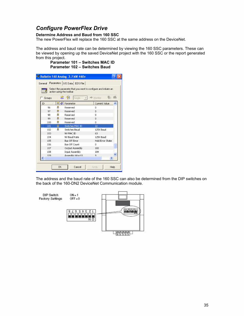
Configure PowerFlex Drive Determine Address and Baud from 160 SSC The new PowerFlex will replace the 160 SSC at the same address on the DeviceNet.
The address and baud rate can be determined by viewing the 160 SSC parameters. These can be viewed by opening up the saved DeviceNet project with the 160 SSC or the report generated from this project.
Parameter 101 – Switches MAC ID Parameter 102 – Switches Baud
The address and the baud rate of the 160 SSC can also be determined from the DIP switches on the back of the 160-DN2 DeviceNet Communication module.
36
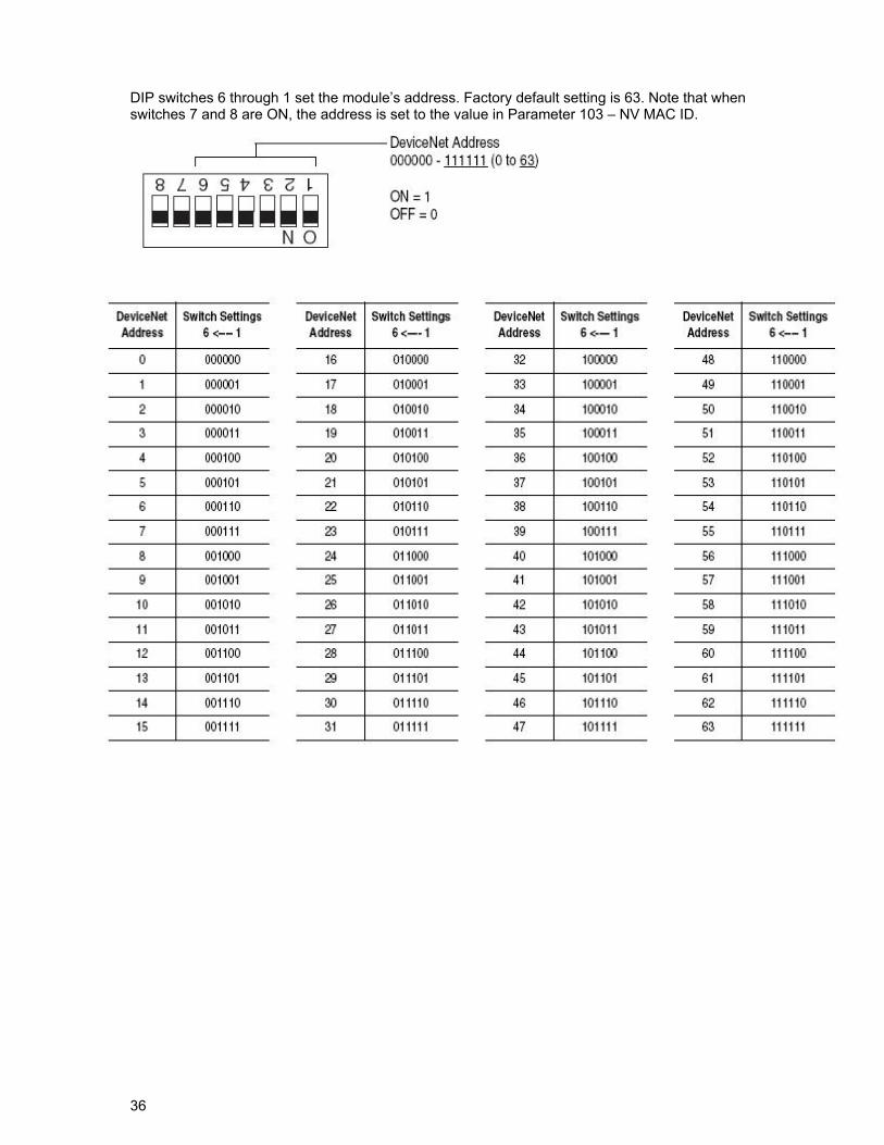
DIP switches 6 through 1 set the module’s address. Factory default setting is 63. Note that when switches 7 and 8 are ON, the address is set to the value in Parameter 103 – NV MAC ID.
37
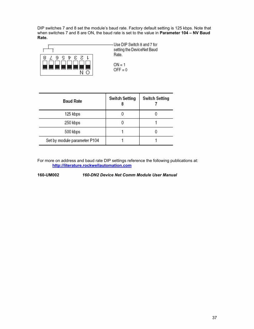
DIP switches 7 and 8 set the module’s baud rate. Factory default setting is 125 kbps. Note that when switches 7 and 8 are ON, the baud rate is set to the value in Parameter 104 – NV Baud Rate.
For more on address and baud rate DIP settings reference the following publications at:
http://literature.rockwellautomation.com
160-UM002 160-DN2 Device Net Comm Module User Manual
38
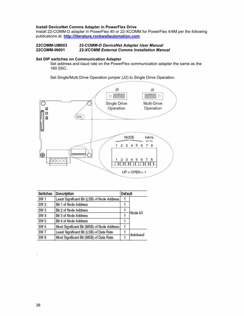
Install DeviceNet Comms Adapter in PowerFlex Drive Install 22-COMM-D adapter in PowerFlex 40 or 22-XCOMM for PowerFlex 4/4M per the following publications at: http://literature.rockwellautomation.com 22COMM-UM003 22-COMM-D DeviceNet Adapter User Manual 22COMM-IN001 22-XCOMM External Comms Installation Manual Set DIP switches on Communication Adapter
Set address and baud rate on the PowerFlex communication adapter the same as the 160 SSC.
Set Single/Multi Drive Operation jumper (J2) to Single Drive Operation.
.
39
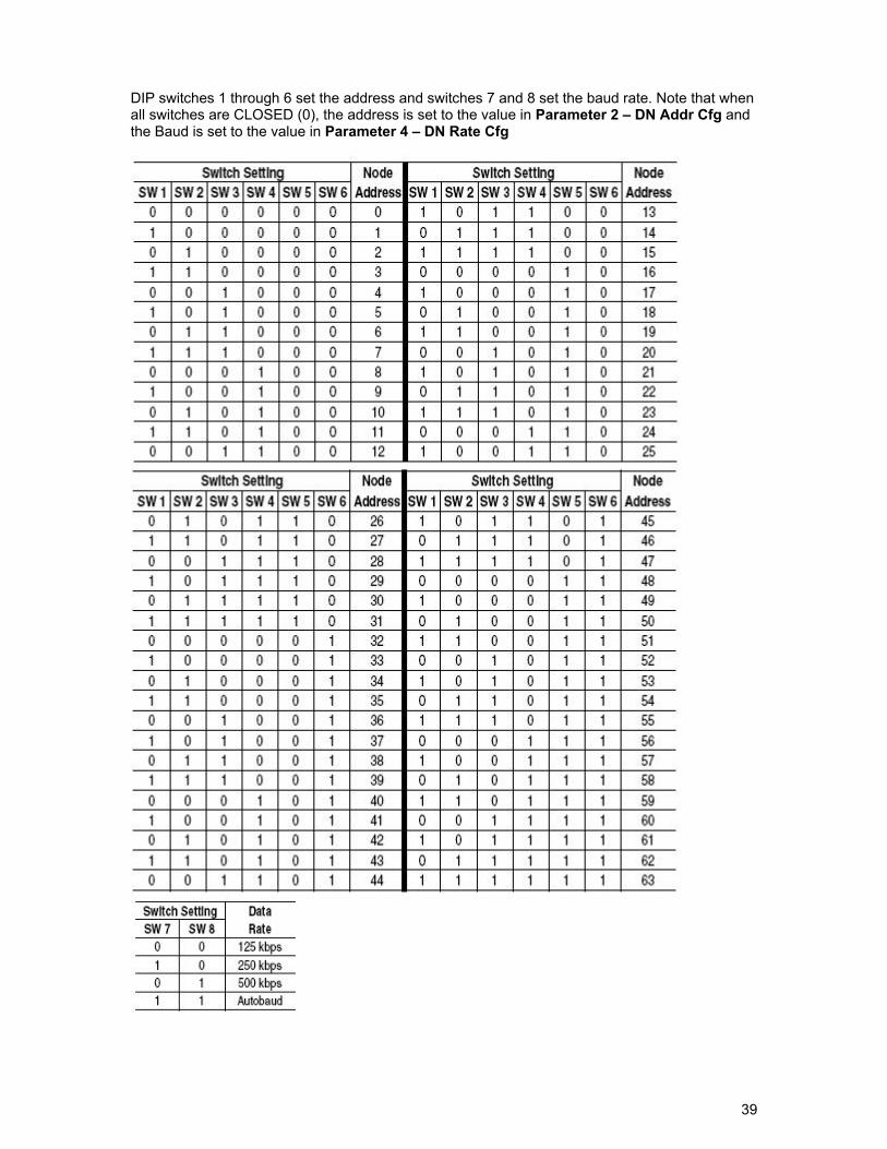
DIP switches 1 through 6 set the address and switches 7 and 8 set the baud rate. Note that when all switches are CLOSED (0), the address is set to the value in Parameter 2 – DN Addr Cfg and the Baud is set to the value in Parameter 4 – DN Rate Cfg
40
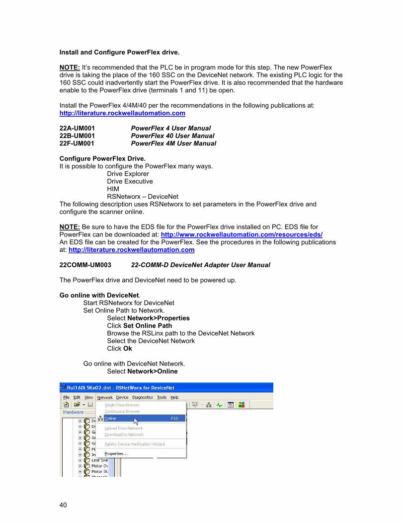
Install and Configure PowerFlex drive. NOTE: It’s recommended that the PLC be in program mode for this step. The new PowerFlex drive is taking the place of the 160 SSC on the DeviceNet network. The existing PLC logic for the 160 SSC could inadvertently start the PowerFlex drive. It is also recommended that the hardware enable to the PowerFlex drive (terminals 1 and 11) be open. Install the PowerFlex 4/4M/40 per the recommendations in the following publications at: http://literature.rockwellautomation.com 22A-UM001 PowerFlex 4 User Manual 22B-UM001 PowerFlex 40 User Manual 22F-UM001 PowerFlex 4M User Manual Configure PowerFlex Drive. It is possible to configure the PowerFlex many ways. Drive Explorer Drive Executive HIM RSNetworx – DeviceNet The following description uses RSNetworx to set parameters in the PowerFlex drive and configure the scanner online. NOTE: Be sure to have the EDS file for the PowerFlex drive installed on PC. EDS file for PowerFlex can be downloaded at: http://www.rockwellautomation.com/resources/eds/ An EDS file can be created for the PowerFlex. See the procedures in the following publications at: http://literature.rockwellautomation.com 22COMM-UM003 22-COMM-D DeviceNet Adapter User Manual The PowerFlex drive and DeviceNet need to be powered up. Go online with DeviceNet.
Start RSNetworx for DeviceNet Set Online Path to Network. Select Network>Properties Click Set Online Path Browse the RSLinx path to the DeviceNet Network Select the DeviceNet Network Click Ok Go online with DeviceNet Network. Select Network>Online
41
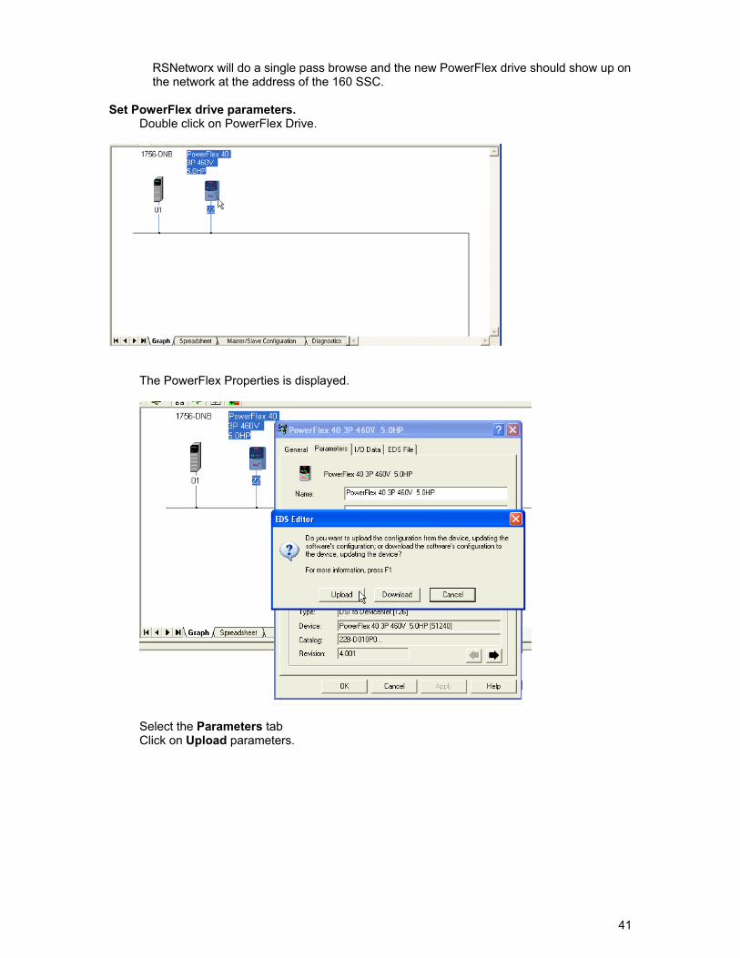
RSNetworx will do a single pass browse and the new PowerFlex drive should show up on the network at the address of the 160 SSC.
Set PowerFlex drive parameters.
Double click on PowerFlex Drive.
The PowerFlex Properties is displayed.
Select the Parameters tab Click on Upload parameters.
42
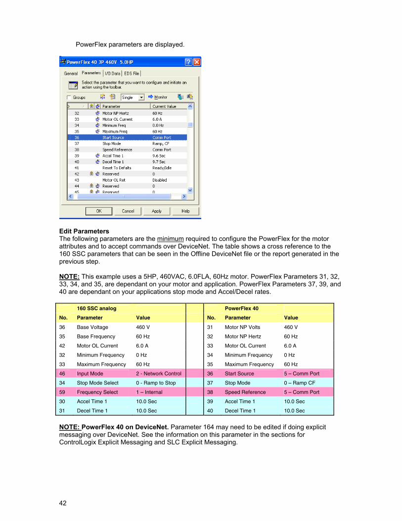
PowerFlex parameters are displayed.
Edit Parameters The following parameters are the minimum required to configure the PowerFlex for the motor attributes and to accept commands over DeviceNet. The table shows a cross reference to the 160 SSC parameters that can be seen in the Offline DeviceNet file or the report generated in the previous step. NOTE: This example uses a 5HP, 460VAC, 6.0FLA, 60Hz motor. PowerFlex Parameters 31, 32, 33, 34, and 35, are dependant on your motor and application. PowerFlex Parameters 37, 39, and 40 are dependant on your applications stop mode and Accel/Decel rates. 160 SSC analog PowerFlex 40
No. Parameter Value No. Parameter Value
36 Base Voltage 460 V 31 Motor NP Volts 460 V
35 Base Frequency 60 Hz 32 Motor NP Hertz 60 Hz
42 Motor OL Current 6.0 A 33 Motor OL Current 6.0 A
32 Minimum Frequency 0 Hz 34 Minimum Frequency 0 Hz
33 Maximum Frequency 60 Hz 35 Maximum Frequency 60 Hz
46 Input Mode 2 - Network Control 36 Start Source 5 – Comm Port
34 Stop Mode Select 0 - Ramp to Stop 37 Stop Mode 0 – Ramp CF
59 Frequency Select 1 – Internal 38 Speed Reference 5 – Comm Port
30 Accel Time 1 10.0 Sec 39 Accel Time 1 10.0 Sec
31 Decel Time 1 10.0 Sec 40 Decel Time 1 10.0 Sec
NOTE: PowerFlex 40 on DeviceNet. Parameter 164 may need to be edited if doing explicit messaging over DeviceNet. See the information on this parameter in the sections for ControlLogix Explicit Messaging and SLC Explicit Messaging.
43
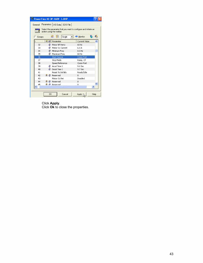
Click Apply. Click Ok to close the properties.
44
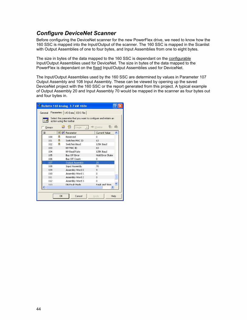
Configure DeviceNet Scanner Before configuring the DeviceNet scanner for the new PowerFlex drive, we need to know how the 160 SSC is mapped into the Input/Output of the scanner. The 160 SSC is mapped in the Scanlist with Output Assemblies of one to four bytes, and Input Assemblies from one to eight bytes. The size in bytes of the data mapped to the 160 SSC is dependant on the configurable Input/Output Assemblies used for DeviceNet. The size in bytes of the data mapped to the PowerFlex is dependant on the fixed Input/Output Assemblies used for DeviceNet. The Input/Output Assemblies used by the 160 SSC are determined by values in Parameter 107 Output Assembly and 108 Input Assembly. These can be viewed by opening up the saved DeviceNet project with the 160 SSC or the report generated from this project. A typical example of Output Assembly 20 and Input Assembly 70 would be mapped in the scanner as four bytes out and four bytes in.
45
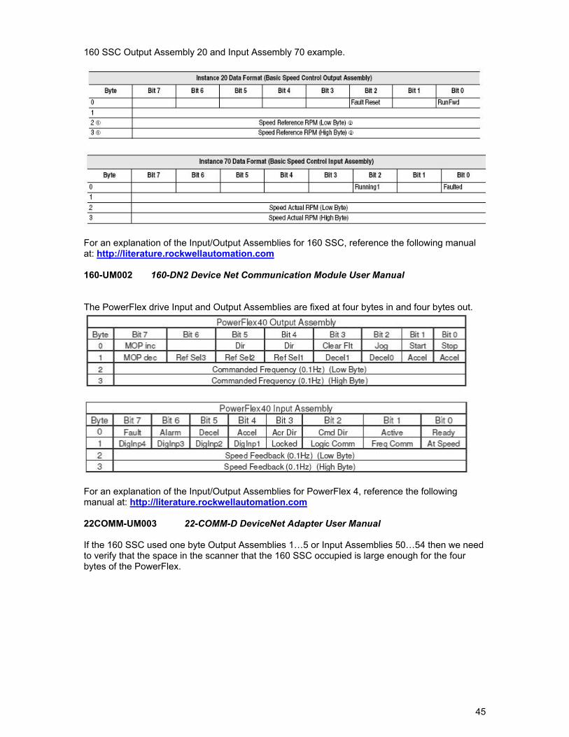
160 SSC Output Assembly 20 and Input Assembly 70 example.
For an explanation of the Input/Output Assemblies for 160 SSC, reference the following manual at: http://literature.rockwellautomation.com 160-UM002 160-DN2 Device Net Communication Module User Manual The PowerFlex drive Input and Output Assemblies are fixed at four bytes in and four bytes out.
For an explanation of the Input/Output Assemblies for PowerFlex 4, reference the following manual at: http://literature.rockwellautomation.com 22COMM-UM003 22-COMM-D DeviceNet Adapter User Manual If the 160 SSC used one byte Output Assemblies 1…5 or Input Assemblies 50…54 then we need to verify that the space in the scanner that the 160 SSC occupied is large enough for the four bytes of the PowerFlex.
46
Go online with DeviceNet. Start RSNetworx for DeviceNet Set Online Path to Network. Select Network>Properties Click Set Online Path Browse the RSLinx path to the DeviceNet Network Select the DeviceNet Network Click Ok Go online with DeviceNet Network. Select Network>Online
When online, RSNetworx will browse and display the devices on the network.
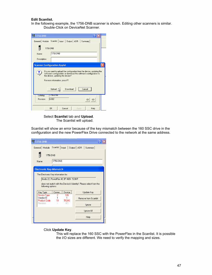
47
Edit Scanlist. In the following example, the 1756-DNB scanner is shown. Editing other scanners is similar.
Double-Click on DeviceNet Scanner.
Select Scanlist tab and Upload.
The Scanlist will upload.
Scanlist will show an error because of the key mismatch between the 160 SSC drive in the configuration and the new PowerFlex Drive connected to the network at the same address.
Click Update Key.
This will replace the 160 SSC with the PowerFlex in the Scanlist. It is possible the I/O sizes are different. We need to verify the mapping and sizes.
48
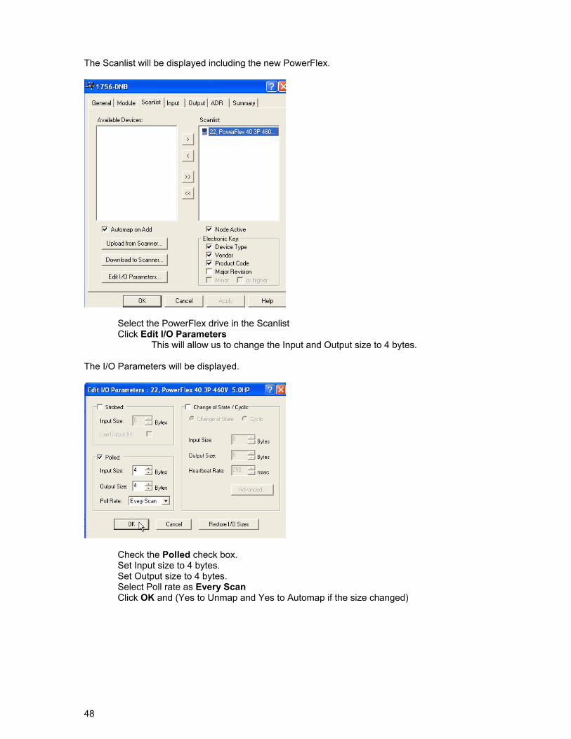
The Scanlist will be displayed including the new PowerFlex.
Select the PowerFlex drive in the Scanlist Click Edit I/O Parameters
This will allow us to change the Input and Output size to 4 bytes. The I/O Parameters will be displayed.
Check the Polled check box. Set Input size to 4 bytes. Set Output size to 4 bytes. Select Poll rate as Every Scan Click OK and (Yes to Unmap and Yes to Automap if the size changed)
49
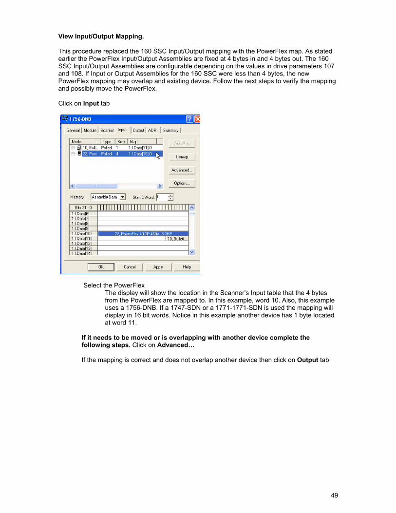
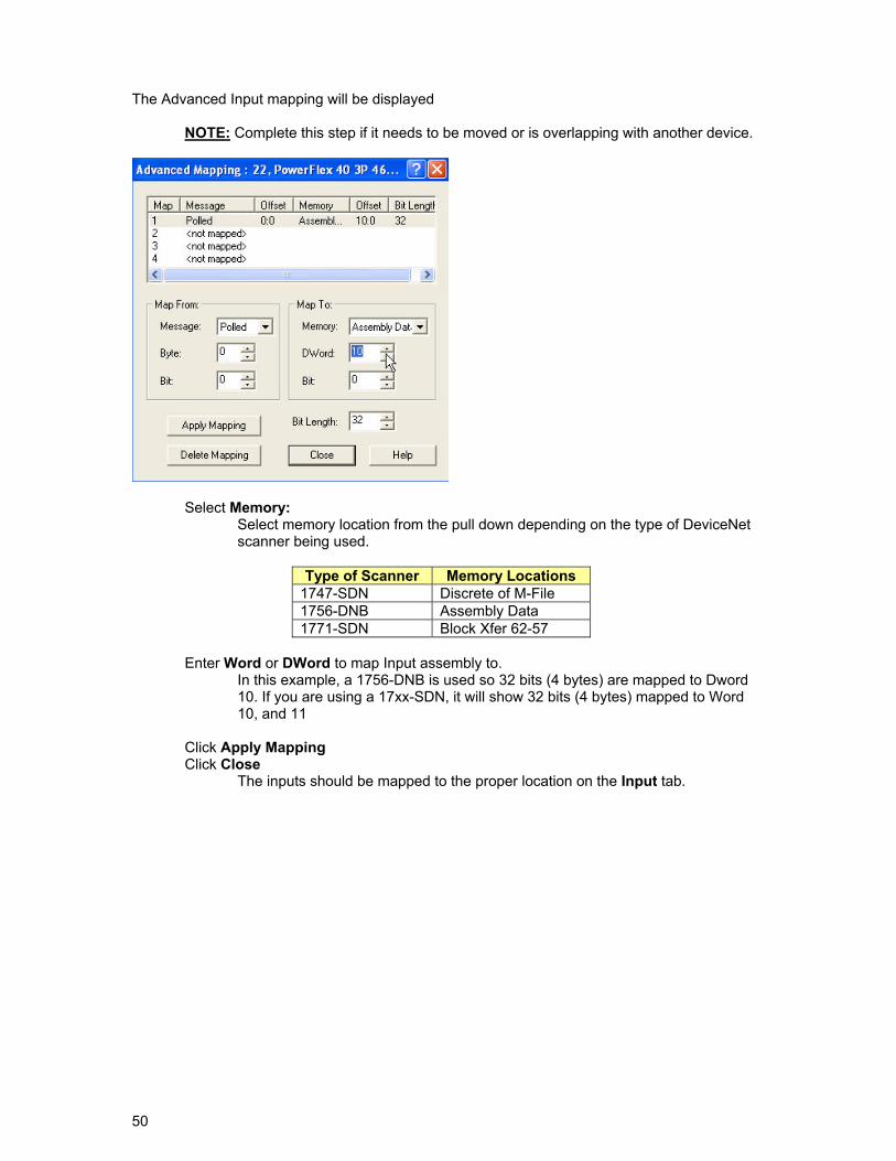
View Input/Output Mapping. This procedure replaced the 160 SSC Input/Output mapping with the PowerFlex map. As stated earlier the PowerFlex Input/Output Assemblies are fixed at 4 bytes in and 4 bytes out. The 160 SSC Input/Output Assemblies are configurable depending on the values in drive parameters 107 and 108. If Input or Output Assemblies for the 160 SSC were less than 4 bytes, the new PowerFlex mapping may overlap and existing device. Follow the next steps to verify the mapping and possibly move the PowerFlex. Click on Input tab
Select the PowerFlex
The display will show the location in the Scanner’s Input table that the 4 bytes from the PowerFlex are mapped to. In this example, word 10. Also, this example uses a 1756-DNB. If a 1747-SDN or a 1771-1771-SDN is used the mapping will display in 16 bit words. Notice in this example another device has 1 byte located at word 11.
If it needs to be moved or is overlapping with another device complete the following steps. Click on Advanced…
If the mapping is correct and does not overlap another device then click on Output tab
50
The Advanced Input mapping will be displayed
NOTE: Complete this step if it needs to be moved or is overlapping with another device.
Select Memory: Select memory location from the pull down depending on the type of DeviceNet scanner being used.
Type of Scanner Memory Locations 1747-SDN Discrete of M-File 1756-DNB Assembly Data 1771-SDN Block Xfer 62-57
Enter Word or DWord to map Input assembly to.
In this example, a 1756-DNB is used so 32 bits (4 bytes) are mapped to Dword 10. If you are using a 17xx-SDN, it will show 32 bits (4 bytes) mapped to Word 10, and 11
Click Apply Mapping
Click Close The inputs should be mapped to the proper location on the Input tab.
51
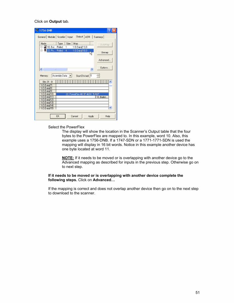
Click on Output tab.
Select the PowerFlex
The display will show the location in the Scanner’s Output table that the four bytes to the PowerFlex are mapped to. In this example, word 10. Also, this example uses a 1756-DNB. If a 1747-SDN or a 1771-1771-SDN is used the mapping will display in 16 bit words. Notice in this example another device has one byte located at word 11. NOTE: If it needs to be moved or is overlapping with another device go to the Advanced mapping as described for inputs in the previous step. Otherwise go on to next step.
If it needs to be moved or is overlapping with another device complete the following steps. Click on Advanced…
If the mapping is correct and does not overlap another device then go on to the next step to download to the scanner.
52
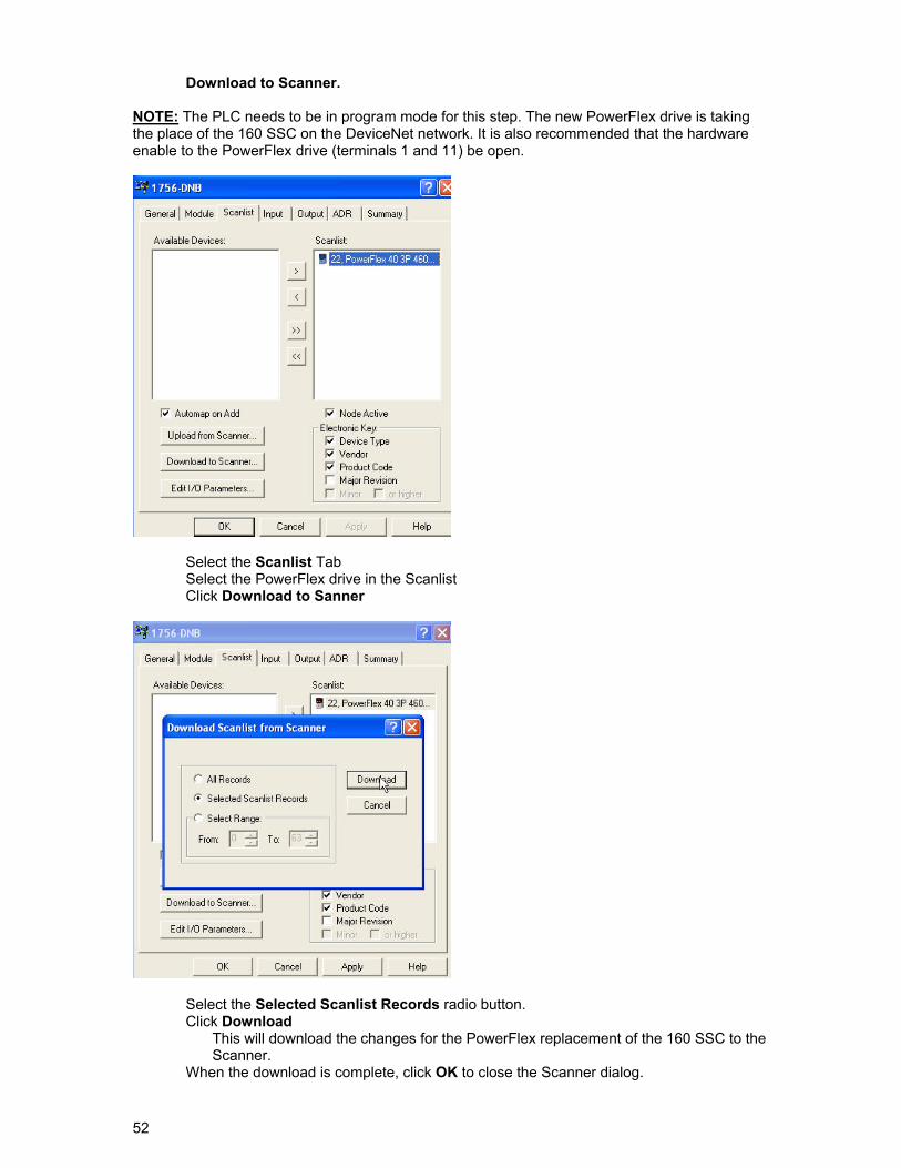
Download to Scanner. NOTE: The PLC needs to be in program mode for this step. The new PowerFlex drive is taking the place of the 160 SSC on the DeviceNet network. It is also recommended that the hardware enable to the PowerFlex drive (terminals 1 and 11) be open.
Select the Scanlist Tab Select the PowerFlex drive in the Scanlist Click Download to Sanner
Select the Selected Scanlist Records radio button. Click Download
This will download the changes for the PowerFlex replacement of the 160 SSC to the Scanner.
When the download is complete, click OK to close the Scanner dialog.
53
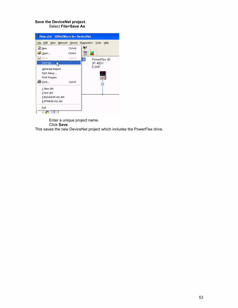
Save the DeviceNet project. Select File>Save As
Enter a unique project name. Click Save.
This saves the new DeviceNet project which includes the PowerFlex drive.
54
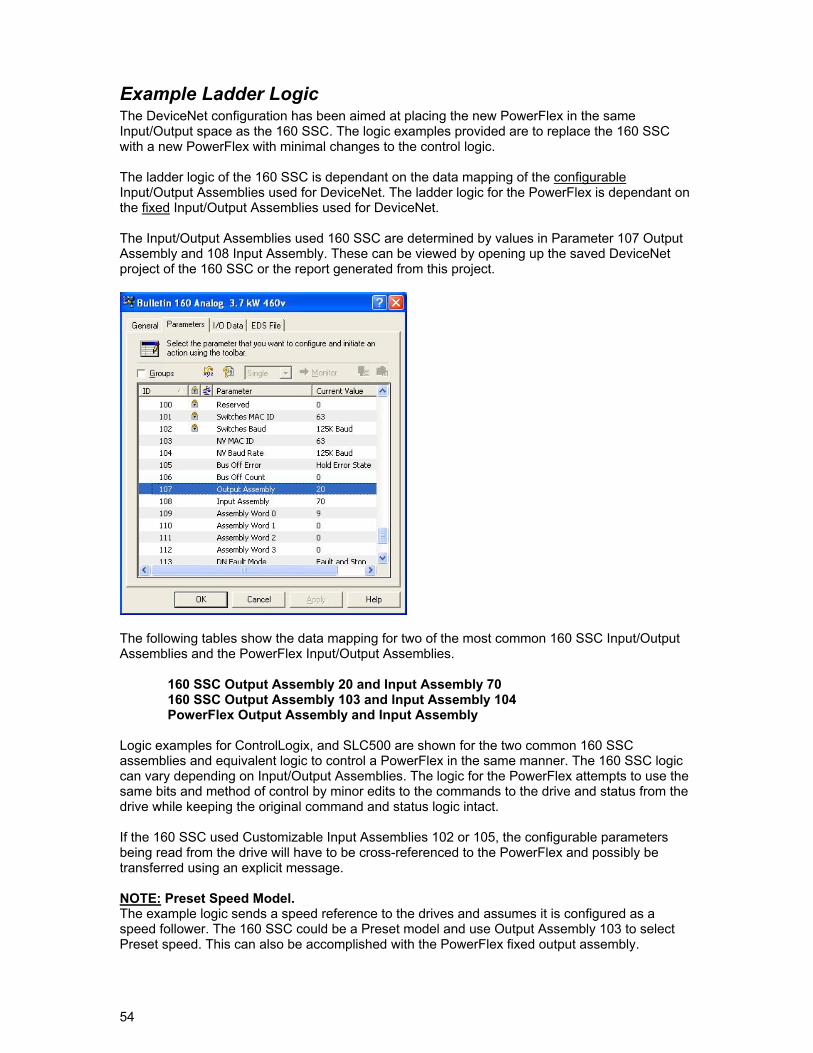
Example Ladder Logic The DeviceNet configuration has been aimed at placing the new PowerFlex in the same Input/Output space as the 160 SSC. The logic examples provided are to replace the 160 SSC with a new PowerFlex with minimal changes to the control logic. The ladder logic of the 160 SSC is dependant on the data mapping of the configurable Input/Output Assemblies used for DeviceNet. The ladder logic for the PowerFlex is dependant on the fixed Input/Output Assemblies used for DeviceNet. The Input/Output Assemblies used 160 SSC are determined by values in Parameter 107 Output Assembly and 108 Input Assembly. These can be viewed by opening up the saved DeviceNet project of the 160 SSC or the report generated from this project.
The following tables show the data mapping for two of the most common 160 SSC Input/Output Assemblies and the PowerFlex Input/Output Assemblies.
160 SSC Output Assembly 20 and Input Assembly 70 160 SSC Output Assembly 103 and Input Assembly 104 PowerFlex Output Assembly and Input Assembly
Logic examples for ControlLogix, and SLC500 are shown for the two common 160 SSC assemblies and equivalent logic to control a PowerFlex in the same manner. The 160 SSC logic can vary depending on Input/Output Assemblies. The logic for the PowerFlex attempts to use the same bits and method of control by minor edits to the commands to the drive and status from the drive while keeping the original command and status logic intact. If the 160 SSC used Customizable Input Assemblies 102 or 105, the configurable parameters being read from the drive will have to be cross-referenced to the PowerFlex and possibly be transferred using an explicit message. NOTE: Preset Speed Model. The example logic sends a speed reference to the drives and assumes it is configured as a speed follower. The 160 SSC could be a Preset model and use Output Assembly 103 to select Preset speed. This can also be accomplished with the PowerFlex fixed output assembly.
55
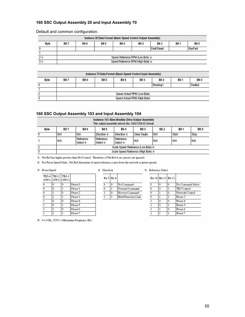
160 SSC Output Assembly 20 and Input Assembly 70 Default and common configuration.
160 SSC Output Assembly 103 and Input Assembly 104
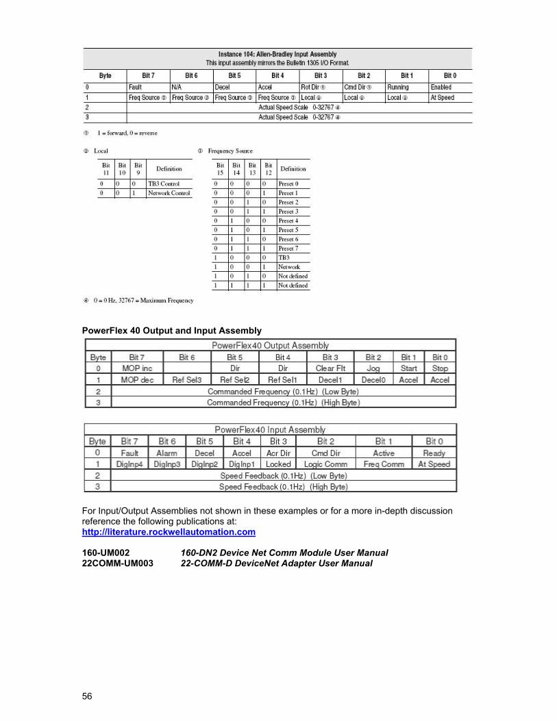
56
PowerFlex 40 Output and Input Assembly
For Input/Output Assemblies not shown in these examples or for a more in-depth discussion reference the following publications at: http://literature.rockwellautomation.com 160-UM002 160-DN2 Device Net Comm Module User Manual 22COMM-UM003 22-COMM-D DeviceNet Adapter User Manual
57
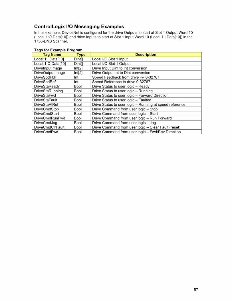
ControlLogix I/O Messaging Examples In this example, DeviceNet is configured for the drive Outputs to start at Slot 1 Output Word 10 (Local:1:O.Data[10]) and drive Inputs to start at Slot 1 Input Word 10 (Local:1:I.Data[10]) in the 1756-DNB Scanner. Tags for Example Program
Tag Name Type Description Local:1:I.Data[10] Dint[] Local I/O Slot 1 Input Local:1:O.Data[10] Dint[] Local I/O Slot 1 Output DriveInputImage Int[2] Drive Input Dint to Int conversion DriveOutputImage Int[2] Drive Output Int to Dint conversion DriveSpdFbk Int Speed Feedback from drive +/- 0-32767 DriveSpdRef Int Speed Reference to drive 0-32767 DriveStaReady Bool Drive Status to user logic – Ready DriveStaRunning Bool Drive Status to user logic – Running DriveStaFwd Bool Drive Status to user logic – Forward Direction DriveStaFault Bool Drive Status to user logic – Faulted DriveStaAtRef Bool Drive Status to user logic – Running at speed reference DriveCmdStop Bool Drive Command from user logic – Stop DriveCmdStart Bool Drive Command from user logic – Start DriveCmdRunFwd Bool Drive Command from user logic – Run Forward DriveCmdJog Bool Drive Command from user logic – Jog DriveCmdClrFault Bool Drive Command from user logic – Clear Fault (reset) DriveCmdFwd Bool Drive Command from user logic – Fwd/Rev Direction
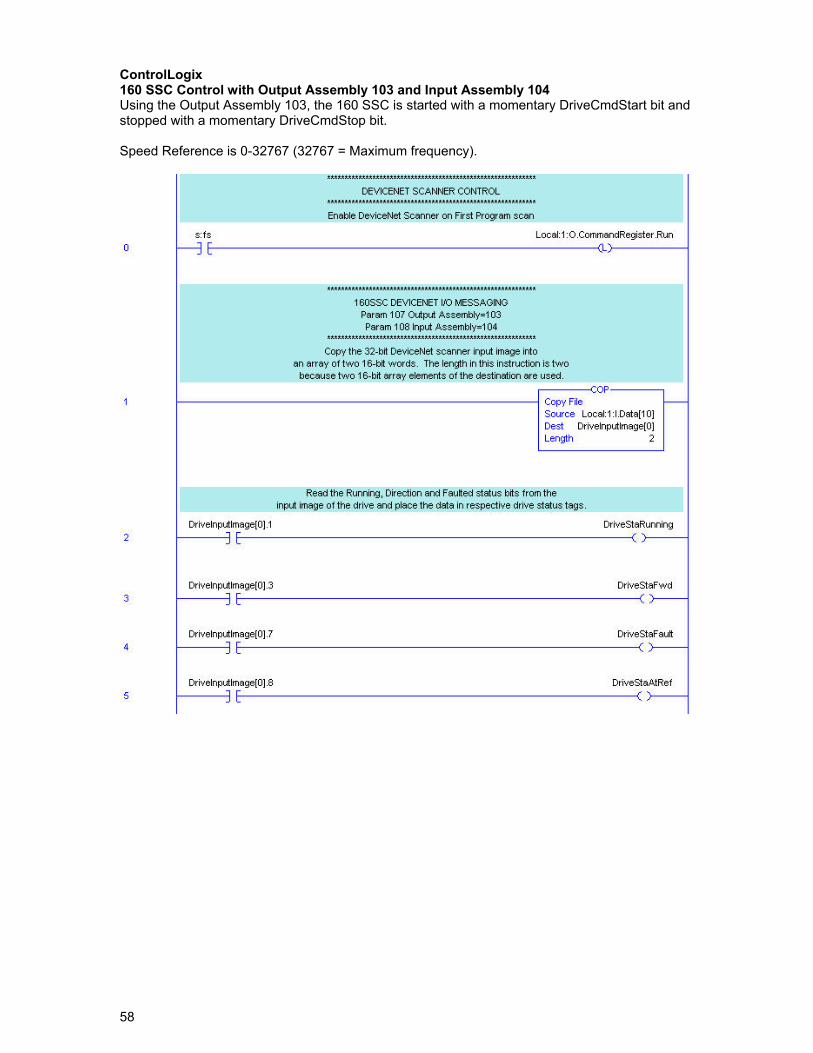
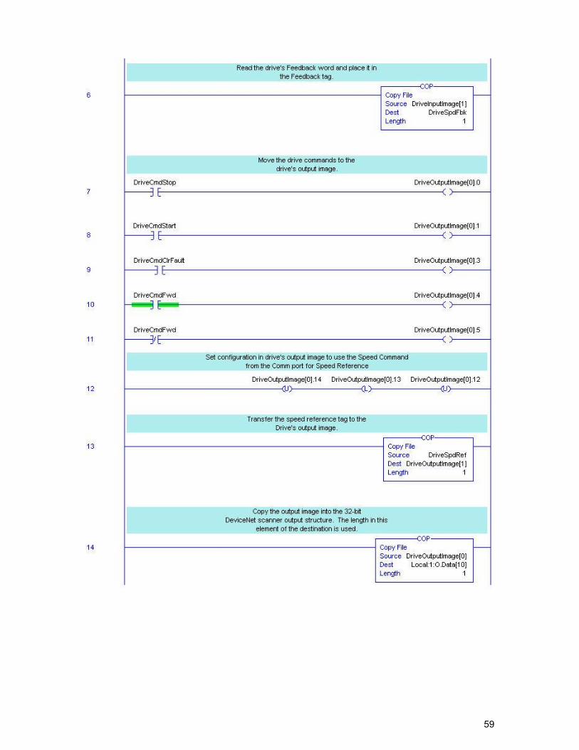
58
ControlLogix 160 SSC Control with Output Assembly 103 and Input Assembly 104 Using the Output Assembly 103, the 160 SSC is started with a momentary DriveCmdStart bit and stopped with a momentary DriveCmdStop bit. Speed Reference is 0-32767 (32767 = Maximum frequency).
59
60
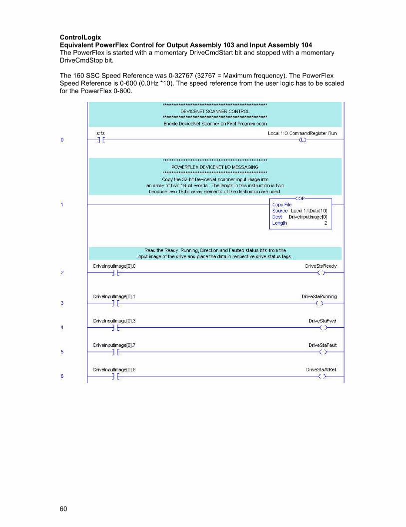
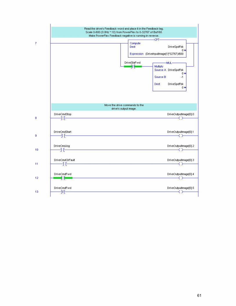
ControlLogix Equivalent PowerFlex Control for Output Assembly 103 and Input Assembly 104 The PowerFlex is started with a momentary DriveCmdStart bit and stopped with a momentary DriveCmdStop bit. The 160 SSC Speed Reference was 0-32767 (32767 = Maximum frequency). The PowerFlex Speed Reference is 0-600 (0.0Hz *10). The speed reference from the user logic has to be scaled for the PowerFlex 0-600.
61
62
63
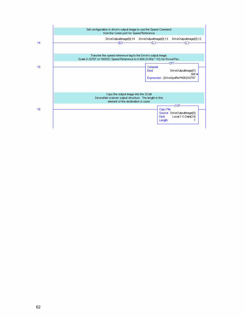
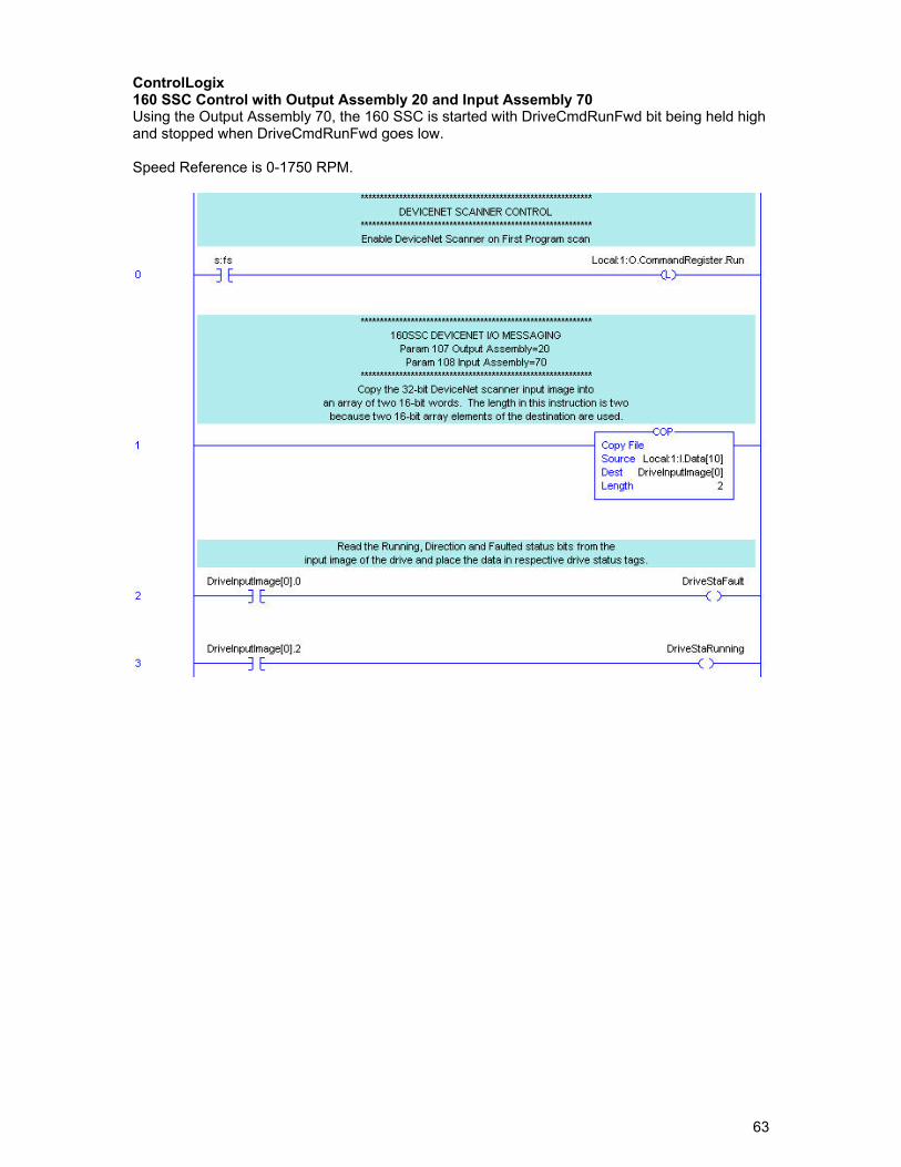
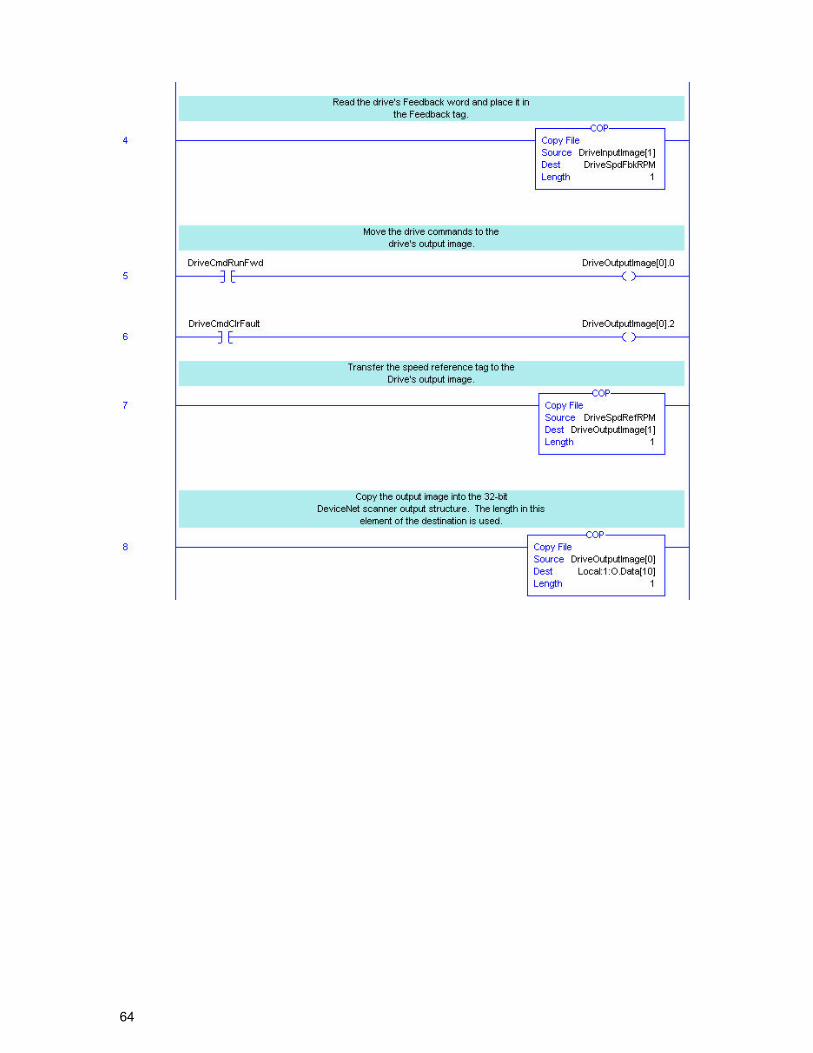
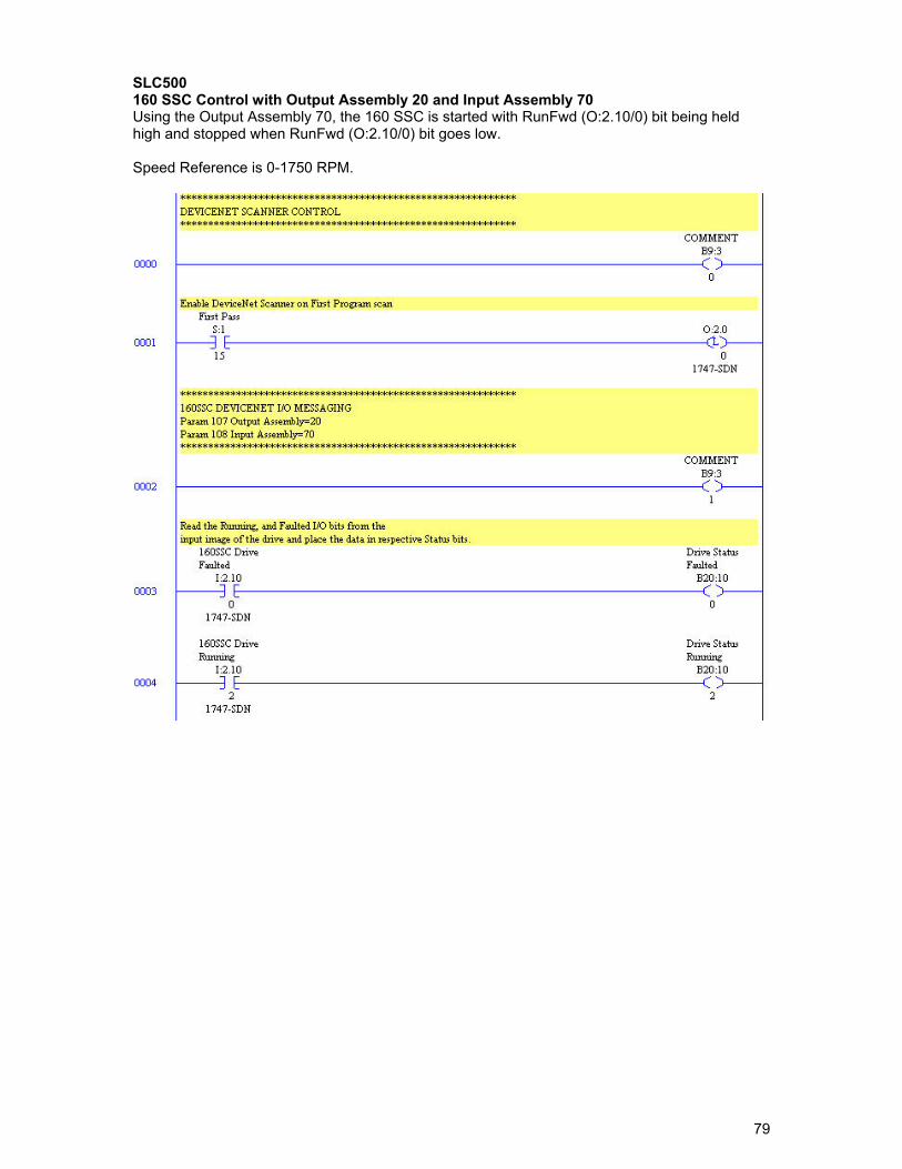
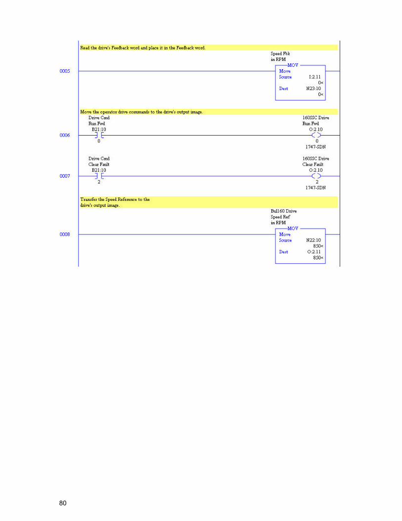
ControlLogix 160 SSC Control with Output Assembly 20 and Input Assembly 70 Using the Output Assembly 70, the 160 SSC is started with DriveCmdRunFwd bit being held high and stopped when DriveCmdRunFwd goes low. Speed Reference is 0-1750 RPM.
64
65
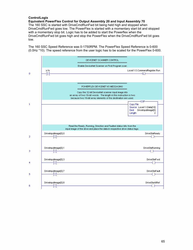
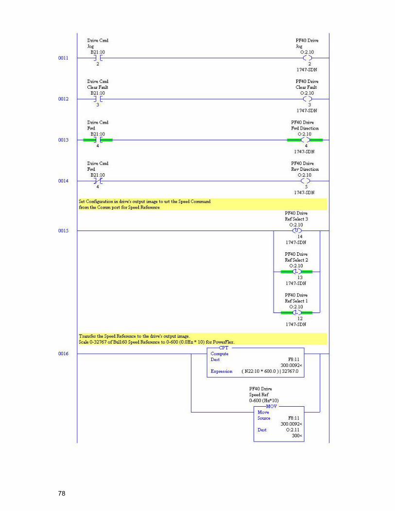
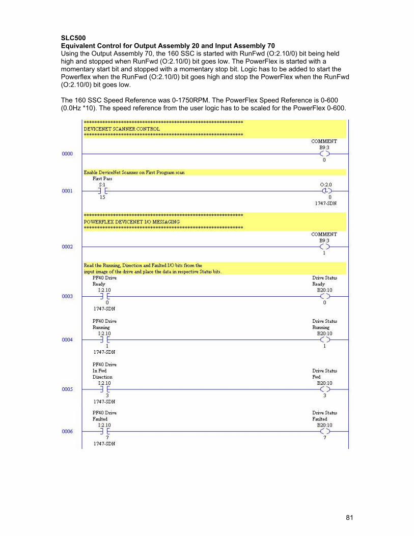
ControlLogix Equivalent PowerFlex Control for Output Assembly 20 and Input Assembly 70 The 160 SSC is started with DriveCmdRunFwd bit being held high and stopped when DriveCmdRunFwd goes low. The PowerFlex is started with a momentary start bit and stopped with a momentary stop bit. Logic has to be added to start the Powerflex when the DriveCmdRunFwd bit goes high and stop the PowerFlex when the DriveCmdRunFwd bit goes low. The 160 SSC Speed Reference was 0-1750RPM. The PowerFlex Speed Reference is 0-600 (0.0Hz *10). The speed reference from the user logic has to be scaled for the PowerFlex 0-600.
66
67
ControlLogix Explicit Messaging Examples Explicit Messaging is used to transfer data that does not require continuous updates. It can also be configured to read or write parameters not included in the fixed Input and Output Assemblies. Two examples are shown for 160 SSC and equivalent for PowerFlex. One example reads the Output current from the drive and the other writes Accel Rate to the drive. NOTE: PowerFlex 40 Explicit Messaging. Writing parameter data to the PowerFlex 40 over the communications port can be stored to RAM only or Non-Volatile Storage (NVS) depending on Parameter A164 (Comm Write Mode). If stored in RAM, the values will be lost at power down. However, if they are stored in NVS, and the controller is programmed to write parameter data frequently, the NVS will quickly exceed its life cycle and cause the drive to malfunction. Parameter A164 (Comm Write Mode) 0 – Save (default) 1 – RAM Only
68
Read Output Current, ParamReadMsg Rungs. The following rung triggers the message to read the Output Current from the drive when bit ParamRead goes from OFF to ON. Bit ParamRead is the result of user’s logic.
Read Output Current, ParamReadMsg Configuration. The message control rungs for reading a value from the 160 SSC and the PowerFlex could be same, but the message configuration is different. The DeviceNet objects differ between the 160 SSC and Powerflex. Following shows the message configuration differences to read the Output Current from a PowerFlex compared to a 160 SSC. For a complete list of DeviceNet objects reference the following publications at: http://literature.rockwellautomation.com 160-UM002 160-DN2 Device Net Comm Module User Manual 22COMM-UM003 22-COMM-D DeviceNet Adapter User Manual For a cross reference of 160 SSC parameters to PowerFlex parameters see the Parameter Cross Reference section at the end.
69
Message Configuration The message type must be CIP Generic.
160 SSC – CIP Generic PowerFlex – CIP Generic
Service Type The service type is the requested DeviceNet service. Available services depend on the class and instance that you are using.
160 SSC – Get Attribute Single (Service Code – e) PowerFlex – Get Attribute Single (Service Code – e)
Class The object type is a DeviceNet class.
160 SSC – b3 (Parameter Table Object) PowerFlex – f (Parameter Object)
Instance The object ID is an instance of a DeviceNet class.
160 SSC – 1 (Parameter Value) PowerFlex – 3 (Parameter #)
Attribute The attribute is a class or instance attribute.
160 SSC – 3 (Parameter #3 Output Current) PowerFlex – 1 (Parameter Value)
Source Element The Source Element is the name of the tag for any data to be sent from the scanner to the drive. A tag must be specified even if it is not used.
160 SSC – blank PowerFlex – blank
Source Length The number of bytes of service data to be sent of received in the message.
160 SSC – 0 PowerFlex – 0
Destination The Destination is the name of the tag that will receive service response data from the drive. A tag must be specified even if it is not used.
160 SSC – DriveOutCurr (Int Tag) PowerFlex – DriveOutCurr (Int Tag)
Path The path includes the following: Name of DeviceNet scanner - DNET01 Communication port on the front of the 1756-DNB scanner. - Always 2. Node address of the DeviceNet adapter on drive – 22
70
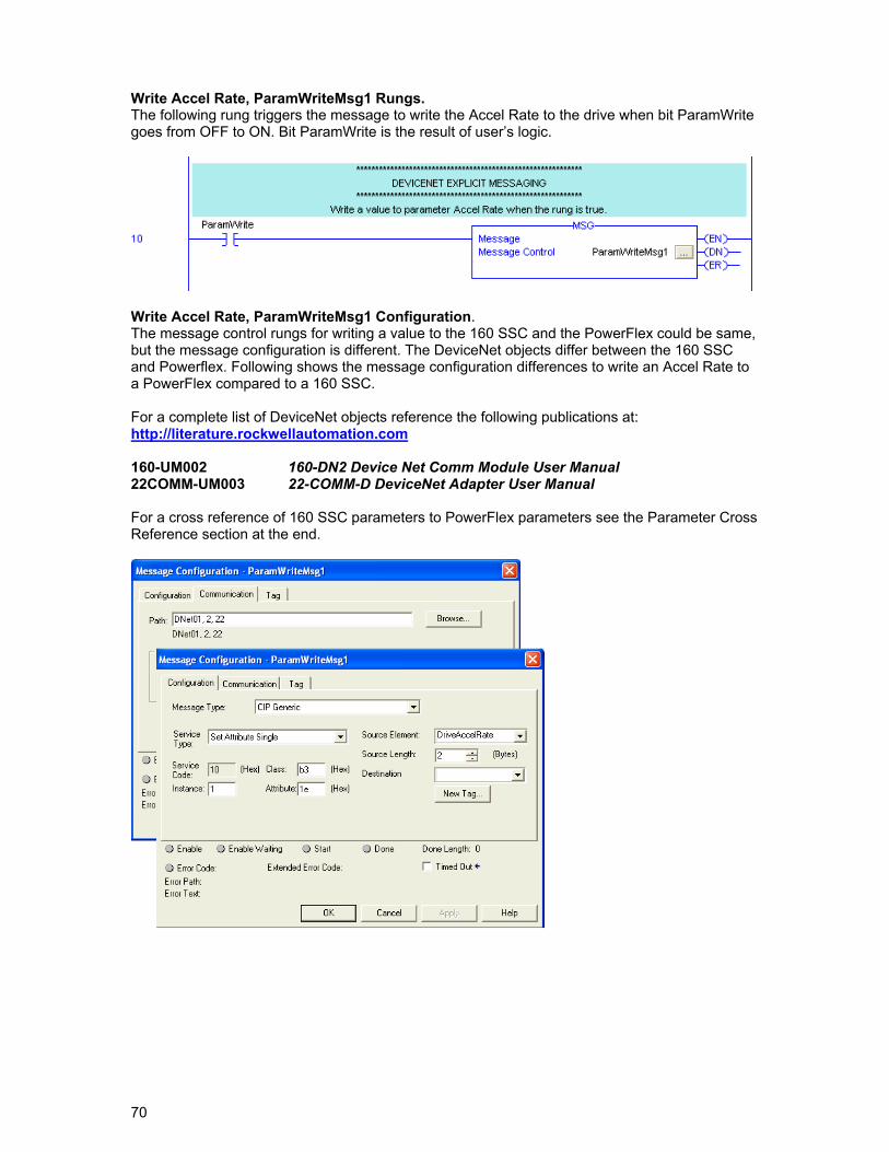
Write Accel Rate, ParamWriteMsg1 Rungs. The following rung triggers the message to write the Accel Rate to the drive when bit ParamWrite goes from OFF to ON. Bit ParamWrite is the result of user’s logic.
Write Accel Rate, ParamWriteMsg1 Configuration. The message control rungs for writing a value to the 160 SSC and the PowerFlex could be same, but the message configuration is different. The DeviceNet objects differ between the 160 SSC and Powerflex. Following shows the message configuration differences to write an Accel Rate to a PowerFlex compared to a 160 SSC. For a complete list of DeviceNet objects reference the following publications at: http://literature.rockwellautomation.com 160-UM002 160-DN2 Device Net Comm Module User Manual 22COMM-UM003 22-COMM-D DeviceNet Adapter User Manual For a cross reference of 160 SSC parameters to PowerFlex parameters see the Parameter Cross Reference section at the end.
71
Message Configuration The message type must be CIP Generic.
160 SSC – CIP Generic PowerFlex – CIP Generic
Service Type The service type is the requested DeviceNet service. Available services depend on the class and instance that you are using.
160 SSC – Set Single Attribute (Service Code – 10) PowerFlex – Set Single Attribute (Service Code – 10)
Class The object type is a DeviceNet class.
160 SSC – b3 (Parameter Table Object) PowerFlex – f (Parameter Object)
Instance The object ID is an instance of a DeviceNet class.
160 SSC – 1 (Parameter Value) PowerFlex – 39 (Parameter #)
Attribute The attribute is a class or instance attribute.
160 SSC – 1e (30 decimal) (Parameter #30 Accel Rate) PowerFlex – 1 (Parameter Value)
Source Element The Source Element is the name of the tag for any data to be sent from the scanner to the drive. A tag must be specified even if it is not used.
160 SSC – DriveAccelRate (Int Tag) PowerFlex – DriveAccelRate (Int Tag)
Source Length The number of bytes of service data to be sent of received in the message.
160 SSC – 2 PowerFlex – 2
Destination The Destination is the name of the tag that will receive service response data from the drive. A tag must be specified even if it is not used.
160 SSC – blank PowerFlex – blank
Path The path includes the following: Name of DeviceNet scanner - DNET01 Communication port on the front of the 1756-DNB scanner. - Always 2. Node address of the DeviceNet adapter on drive – 22
72
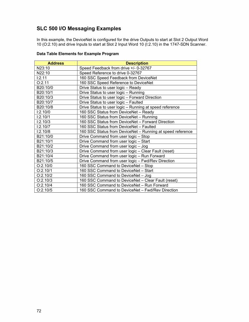
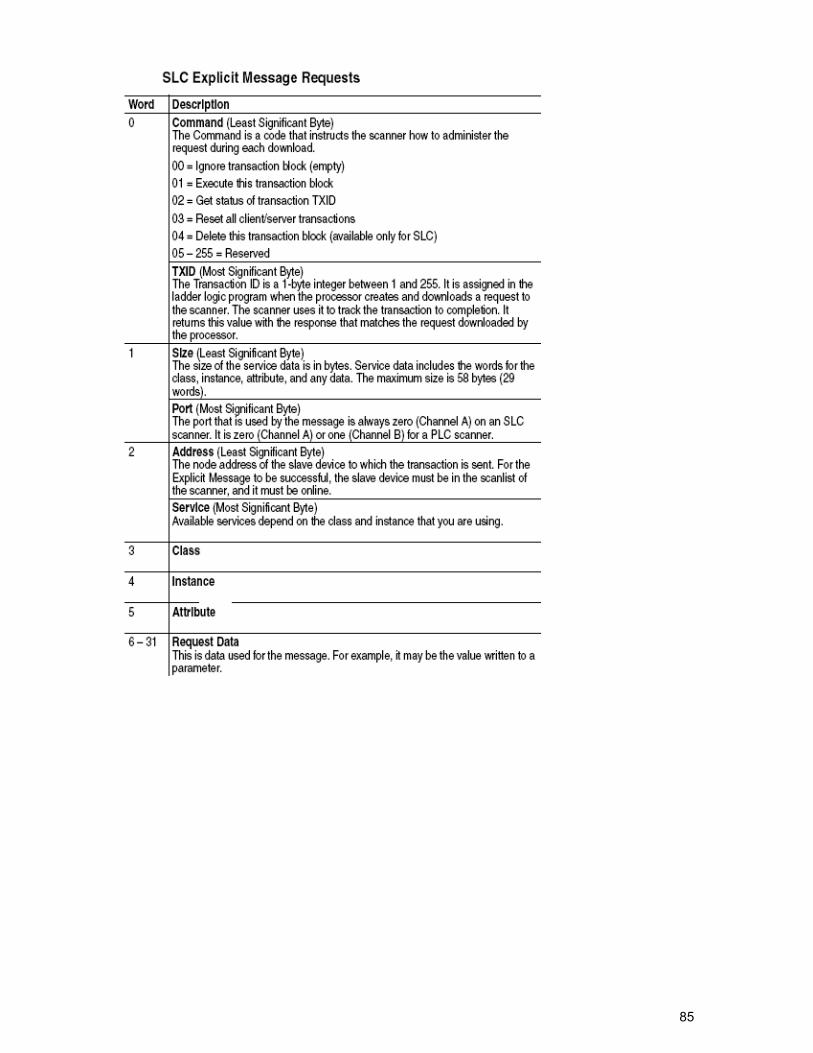
SLC 500 I/O Messaging Examples In this example, the DeviceNet is configured for the drive Outputs to start at Slot 2 Output Word 10 (O:2.10) and drive Inputs to start at Slot 2 Input Word 10 (I:2.10) in the 1747-SDN Scanner. Data Table Elements for Example Program
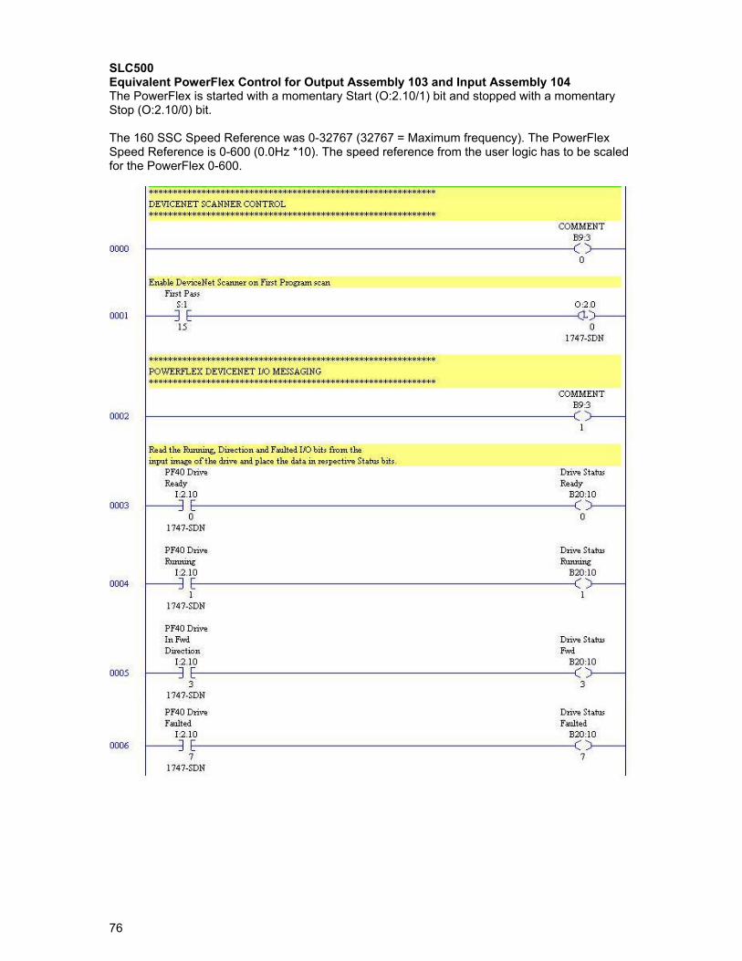
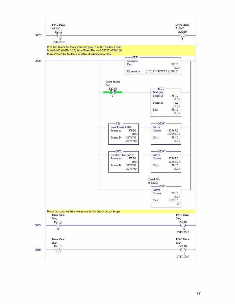
Address Description N23:10 Speed Feedback from drive +/- 0-32767 N22:10 Speed Reference to drive 0-32767 I:2.11 160 SSC Speed Feedback from DeviceNet O:2.11 160 SSC Speed Reference to DeviceNet B20:10/0 Drive Status to user logic – Ready B20:10/1 Drive Status to user logic – Running B20:10/3 Drive Status to user logic – Forward Direction B20:10/7 Drive Status to user logic – Faulted B20:10/8 Drive Status to user logic – Running at speed reference I:2.10/0 160 SSC Status from DeviceNet – Ready I:2.10/1 160 SSC Status from DeviceNet – Running I:2.10/3 160 SSC Status from DeviceNet – Forward Direction I:2.10/7 160 SSC Status from DeviceNet – Faulted I:2.10/8 160 SSC Status from DeviceNet – Running at speed reference B21:10/0 Drive Command from user logic – Stop B21:10/1 Drive Command from user logic – Start B21:10/2 Drive Command from user logic – Jog B21:10/3 Drive Command from user logic – Clear Fault (reset) B21:10/4 Drive Command from user logic – Run Forward B21:10/5 Drive Command from user logic – Fwd/Rev Direction O:2.10/0 160 SSC Command to DeviceNet – Stop O:2.10/1 160 SSC Command to DeviceNet – Start O:2.10/2 160 SSC Command to DeviceNet – Jog O:2.10/3 160 SSC Command to DeviceNet – Clear Fault (reset) O:2.10/4 160 SSC Command to DeviceNet – Run Forward O:2.10/5 160 SSC Command to DeviceNet – Fwd/Rev Direction
73
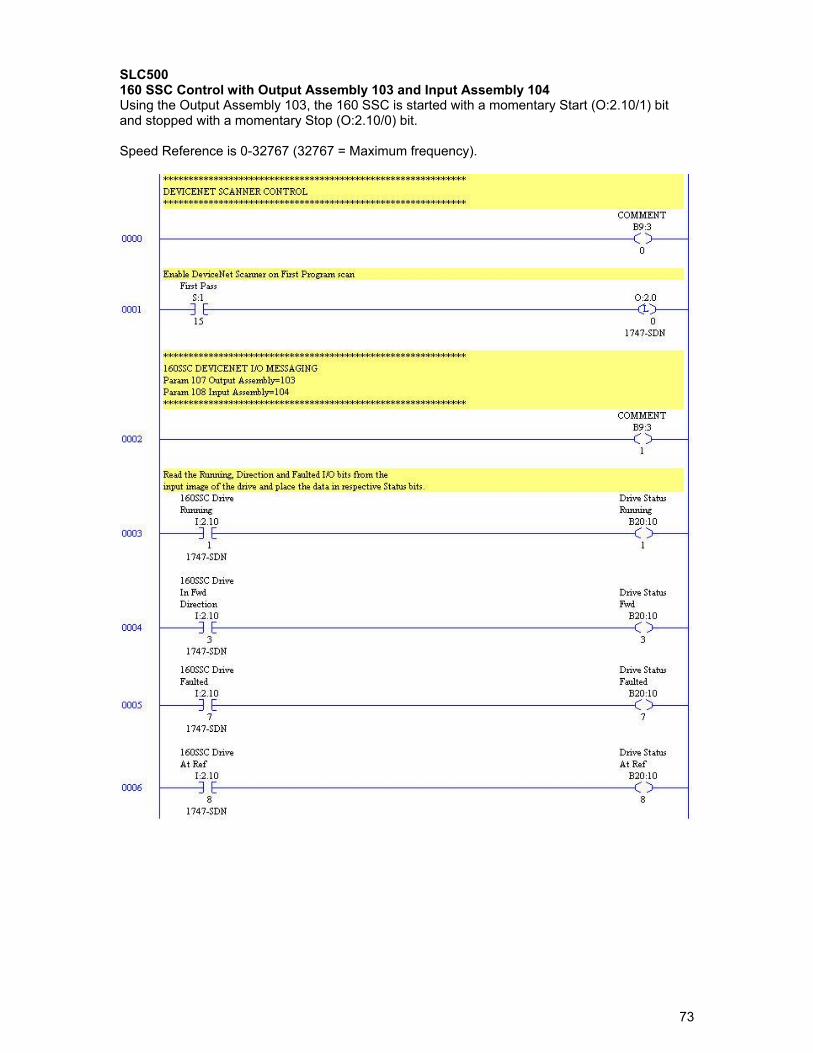
SLC500 160 SSC Control with Output Assembly 103 and Input Assembly 104 Using the Output Assembly 103, the 160 SSC is started with a momentary Start (O:2.10/1) bit and stopped with a momentary Stop (O:2.10/0) bit. Speed Reference is 0-32767 (32767 = Maximum frequency).
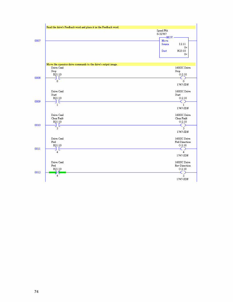
74
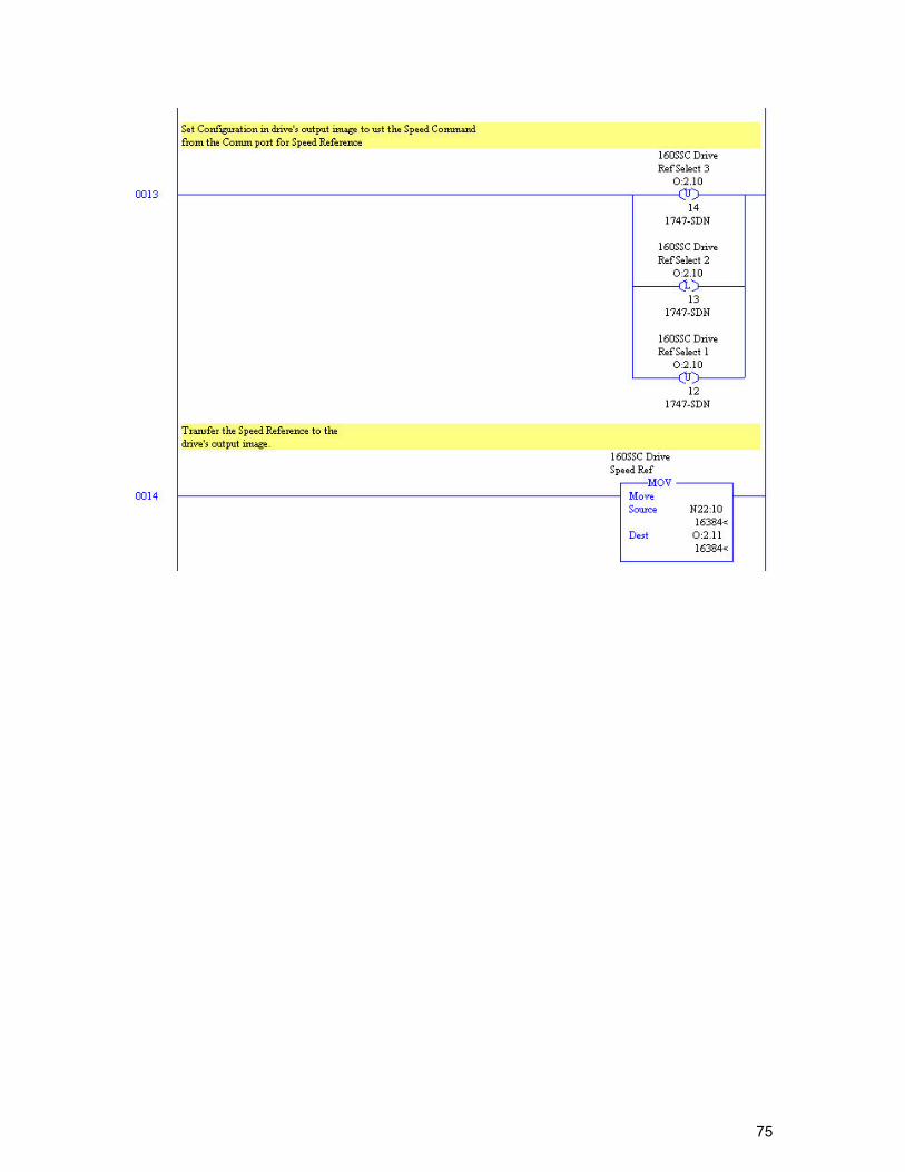
75
76
SLC500 Equivalent PowerFlex Control for Output Assembly 103 and Input Assembly 104 The PowerFlex is started with a momentary Start (O:2.10/1) bit and stopped with a momentary Stop (O:2.10/0) bit. The 160 SSC Speed Reference was 0-32767 (32767 = Maximum frequency). The PowerFlex Speed Reference is 0-600 (0.0Hz *10). The speed reference from the user logic has to be scaled for the PowerFlex 0-600.
77
78
79
SLC500 160 SSC Control with Output Assembly 20 and Input Assembly 70 Using the Output Assembly 70, the 160 SSC is started with RunFwd (O:2.10/0) bit being held high and stopped when RunFwd (O:2.10/0) bit goes low. Speed Reference is 0-1750 RPM.
80
81
SLC500 Equivalent Control for Output Assembly 20 and Input Assembly 70 Using the Output Assembly 70, the 160 SSC is started with RunFwd (O:2.10/0) bit being held high and stopped when RunFwd (O:2.10/0) bit goes low. The PowerFlex is started with a momentary start bit and stopped with a momentary stop bit. Logic has to be added to start the Powerflex when the RunFwd (O:2.10/0) bit goes high and stop the PowerFlex when the RunFwd (O:2.10/0) bit goes low. The 160 SSC Speed Reference was 0-1750RPM. The PowerFlex Speed Reference is 0-600 (0.0Hz *10). The speed reference from the user logic has to be scaled for the PowerFlex 0-600.
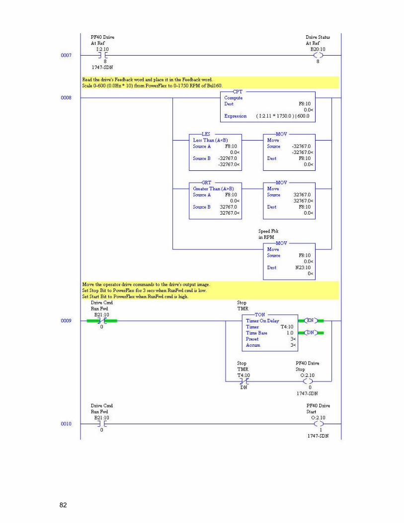
82
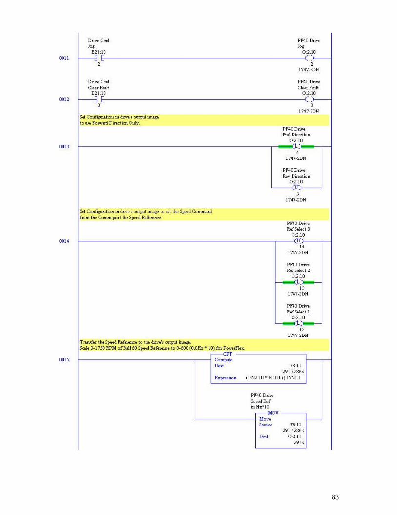
83
84
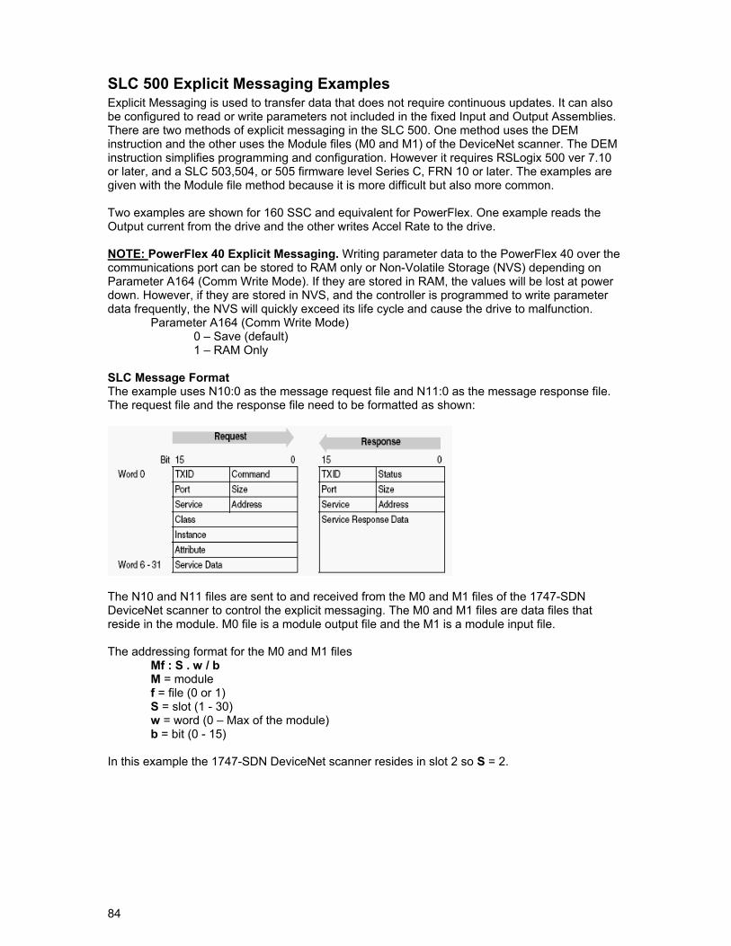
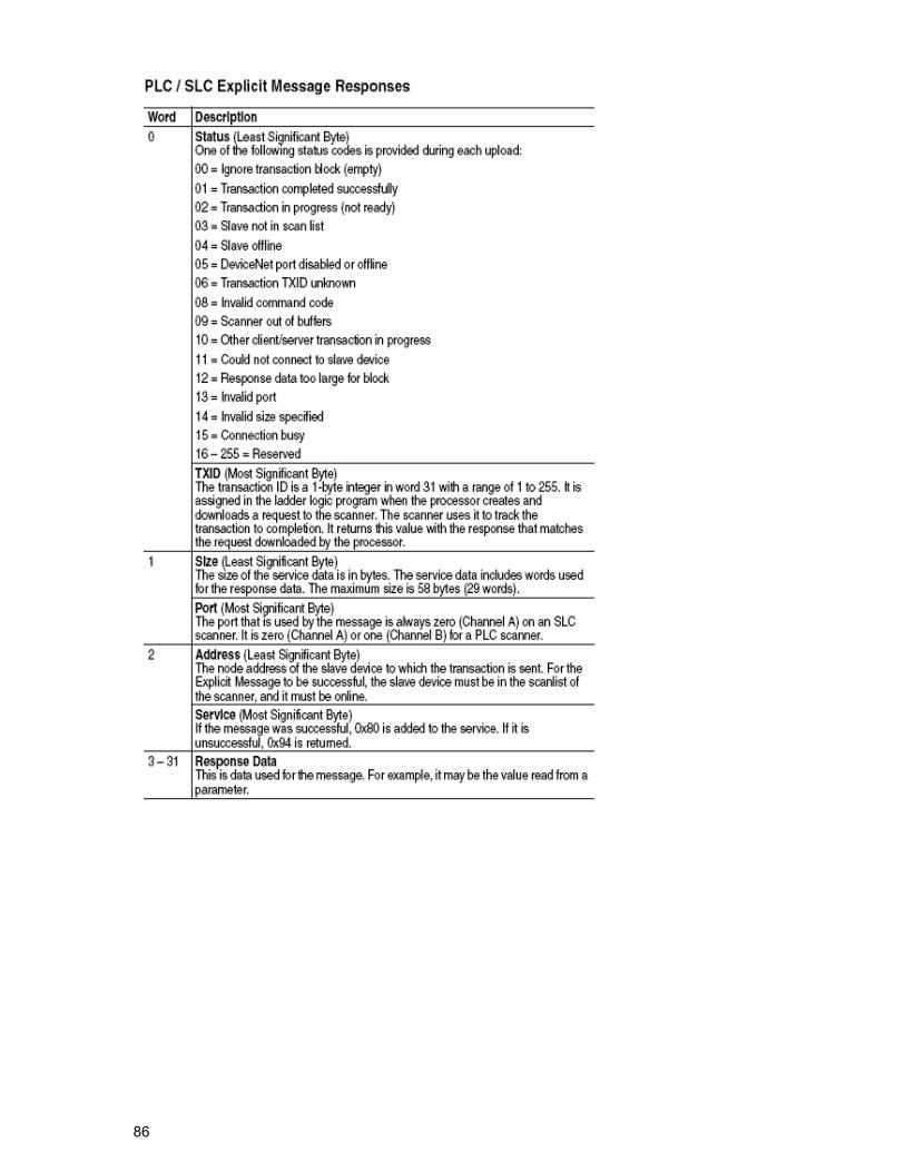
SLC 500 Explicit Messaging Examples Explicit Messaging is used to transfer data that does not require continuous updates. It can also be configured to read or write parameters not included in the fixed Input and Output Assemblies. There are two methods of explicit messaging in the SLC 500. One method uses the DEM instruction and the other uses the Module files (M0 and M1) of the DeviceNet scanner. The DEM instruction simplifies programming and configuration. However it requires RSLogix 500 ver 7.10 or later, and a SLC 503,504, or 505 firmware level Series C, FRN 10 or later. The examples are given with the Module file method because it is more difficult but also more common. Two examples are shown for 160 SSC and equivalent for PowerFlex. One example reads the Output current from the drive and the other writes Accel Rate to the drive. NOTE: PowerFlex 40 Explicit Messaging. Writing parameter data to the PowerFlex 40 over the communications port can be stored to RAM only or Non-Volatile Storage (NVS) depending on Parameter A164 (Comm Write Mode). If they are stored in RAM, the values will be lost at power down. However, if they are stored in NVS, and the controller is programmed to write parameter data frequently, the NVS will quickly exceed its life cycle and cause the drive to malfunction. Parameter A164 (Comm Write Mode) 0 – Save (default) 1 – RAM Only SLC Message Format The example uses N10:0 as the message request file and N11:0 as the message response file. The request file and the response file need to be formatted as shown:
The N10 and N11 files are sent to and received from the M0 and M1 files of the 1747-SDN DeviceNet scanner to control the explicit messaging. The M0 and M1 files are data files that reside in the module. M0 file is a module output file and the M1 is a module input file. The addressing format for the M0 and M1 files
Mf : S . w / b M = module f = file (0 or 1) S = slot (1 - 30) w = word (0 – Max of the module) b = bit (0 - 15)
In this example the 1747-SDN DeviceNet scanner resides in slot 2 so S = 2.
85
86
87
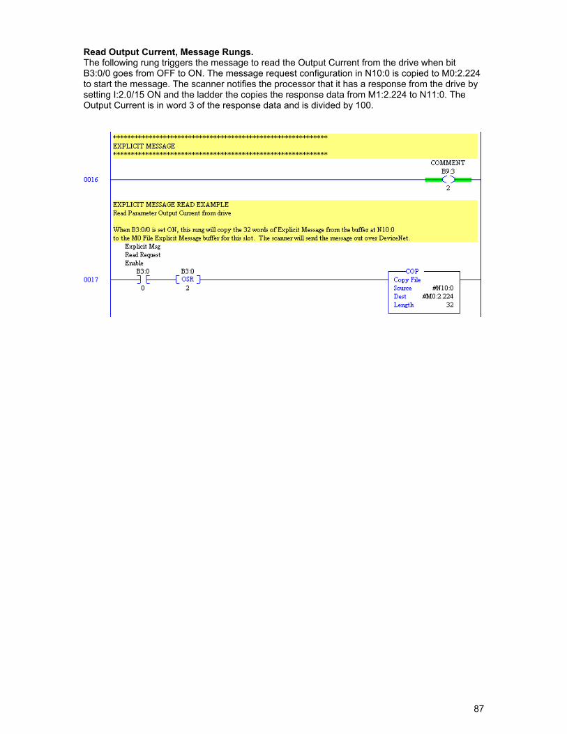
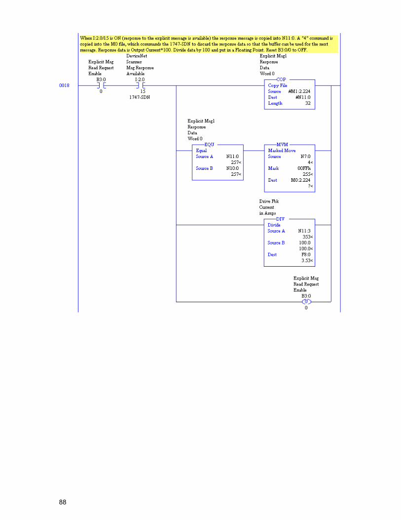
Read Output Current, Message Rungs. The following rung triggers the message to read the Output Current from the drive when bit B3:0/0 goes from OFF to ON. The message request configuration in N10:0 is copied to M0:2.224 to start the message. The scanner notifies the processor that it has a response from the drive by setting I:2.0/15 ON and the ladder the copies the response data from M1:2.224 to N11:0. The Output Current is in word 3 of the response data and is divided by 100.
88
89
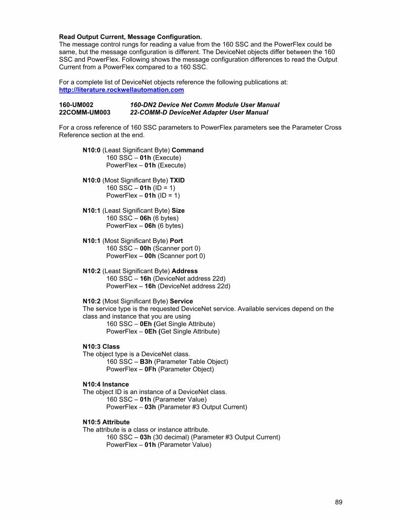
Read Output Current, Message Configuration. The message control rungs for reading a value from the 160 SSC and the PowerFlex could be same, but the message configuration is different. The DeviceNet objects differ between the 160 SSC and PowerFlex. Following shows the message configuration differences to read the Output Current from a PowerFlex compared to a 160 SSC. For a complete list of DeviceNet objects reference the following publications at: http://literature.rockwellautomation.com 160-UM002 160-DN2 Device Net Comm Module User Manual 22COMM-UM003 22-COMM-D DeviceNet Adapter User Manual For a cross reference of 160 SSC parameters to PowerFlex parameters see the Parameter Cross Reference section at the end.
N10:0 (Least Significant Byte) Command 160 SSC – 01h (Execute) PowerFlex – 01h (Execute)
N10:0 (Most Significant Byte) TXID
160 SSC – 01h (ID = 1) PowerFlex – 01h (ID = 1)
N10:1 (Least Significant Byte) Size
160 SSC – 06h (6 bytes) PowerFlex – 06h (6 bytes)
N10:1 (Most Significant Byte) Port
160 SSC – 00h (Scanner port 0) PowerFlex – 00h (Scanner port 0)
N10:2 (Least Significant Byte) Address
160 SSC – 16h (DeviceNet address 22d) PowerFlex – 16h (DeviceNet address 22d)
N10:2 (Most Significant Byte) Service The service type is the requested DeviceNet service. Available services depend on the class and instance that you are using
160 SSC – 0Eh (Get Single Attribute) PowerFlex – 0Eh (Get Single Attribute)
N10:3 Class The object type is a DeviceNet class.
160 SSC – B3h (Parameter Table Object) PowerFlex – 0Fh (Parameter Object)
N10:4 Instance The object ID is an instance of a DeviceNet class.
160 SSC – 01h (Parameter Value) PowerFlex – 03h (Parameter #3 Output Current)
N10:5 Attribute The attribute is a class or instance attribute.
160 SSC – 03h (30 decimal) (Parameter #3 Output Current) PowerFlex – 01h (Parameter Value)
90
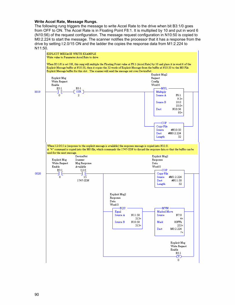
Write Accel Rate, Message Rungs. The following rung triggers the message to write Accel Rate to the drive when bit B3:1/0 goes from OFF to ON. The Accel Rate is in Floating Point F8:1. It is multiplied by 10 and put in word 6 (N10:56) of the request configuration. The message request configuration in N10:50 is copied to M0:2.224 to start the message. The scanner notifies the processor that it has a response from the drive by setting I:2.0/15 ON and the ladder the copies the response data from M1:2.224 to N11:50.
91
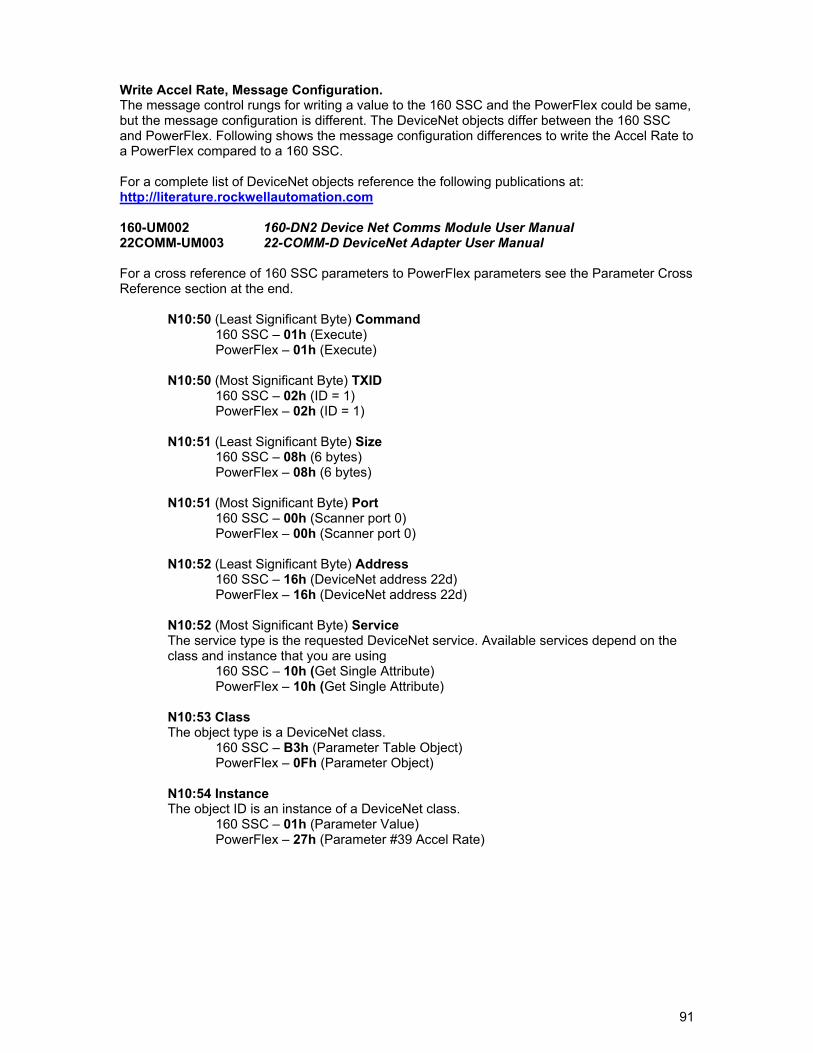
Write Accel Rate, Message Configuration. The message control rungs for writing a value to the 160 SSC and the PowerFlex could be same, but the message configuration is different. The DeviceNet objects differ between the 160 SSC and PowerFlex. Following shows the message configuration differences to write the Accel Rate to a PowerFlex compared to a 160 SSC. For a complete list of DeviceNet objects reference the following publications at: http://literature.rockwellautomation.com 160-UM002 160-DN2 Device Net Comms Module User Manual 22COMM-UM003 22-COMM-D DeviceNet Adapter User Manual For a cross reference of 160 SSC parameters to PowerFlex parameters see the Parameter Cross Reference section at the end.
N10:50 (Least Significant Byte) Command 160 SSC – 01h (Execute) PowerFlex – 01h (Execute)
N10:50 (Most Significant Byte) TXID
160 SSC – 02h (ID = 1) PowerFlex – 02h (ID = 1)
N10:51 (Least Significant Byte) Size
160 SSC – 08h (6 bytes) PowerFlex – 08h (6 bytes)
N10:51 (Most Significant Byte) Port
160 SSC – 00h (Scanner port 0) PowerFlex – 00h (Scanner port 0)
N10:52 (Least Significant Byte) Address
160 SSC – 16h (DeviceNet address 22d) PowerFlex – 16h (DeviceNet address 22d)
N10:52 (Most Significant Byte) Service The service type is the requested DeviceNet service. Available services depend on the class and instance that you are using
160 SSC – 10h (Get Single Attribute) PowerFlex – 10h (Get Single Attribute)
N10:53 Class The object type is a DeviceNet class.
160 SSC – B3h (Parameter Table Object) PowerFlex – 0Fh (Parameter Object)
N10:54 Instance The object ID is an instance of a DeviceNet class.
160 SSC – 01h (Parameter Value) PowerFlex – 27h (Parameter #39 Accel Rate)
92
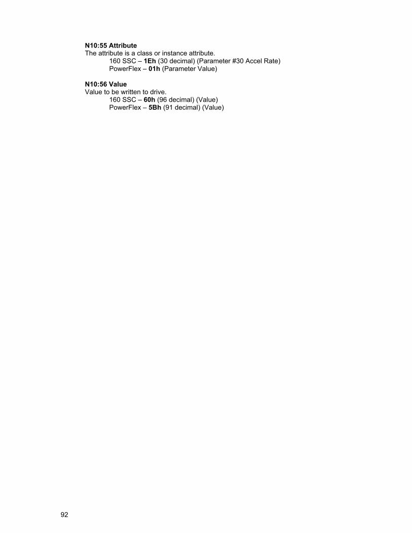
N10:55 Attribute The attribute is a class or instance attribute.
160 SSC – 1Eh (30 decimal) (Parameter #30 Accel Rate) PowerFlex – 01h (Parameter Value)
N10:56 Value Value to be written to drive.
160 SSC – 60h (96 decimal) (Value) PowerFlex – 5Bh (91 decimal) (Value)
93
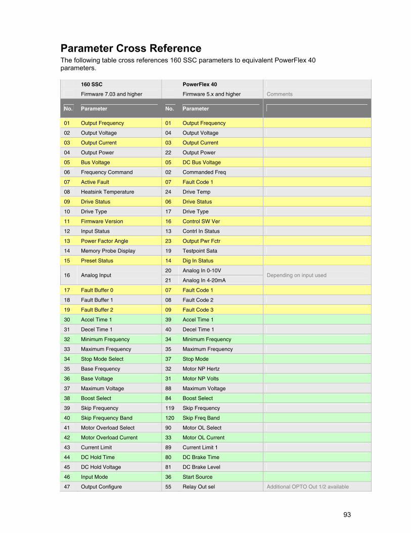
Parameter Cross Reference The following table cross references 160 SSC parameters to equivalent PowerFlex 40 parameters.
160 SSC PowerFlex 40
Firmware 7.03 and higher Firmware 5.x and higher Comments
No. Parameter No. Parameter
01 Output Frequency 01 Output Frequency
02 Output Voltage 04 Output Voltage
03 Output Current 03 Output Current
04 Output Power 22 Output Power
05 Bus Voltage 05 DC Bus Voltage
06 Frequency Command 02 Commanded Freq
07 Active Fault 07 Fault Code 1
08 Heatsink Temperature 24 Drive Temp
09 Drive Status 06 Drive Status
10 Drive Type 17 Drive Type
11 Firmware Version 16 Control SW Ver
12 Input Status 13 Contrl In Status
13 Power Factor Angle 23 Output Pwr Fctr
14 Memory Probe Display 19 Testpoint Sata
15 Preset Status 14 Dig In Status
20 Analog In 0-10V 16 Analog Input
21 Analog In 4-20mA Depending on input used
17 Fault Buffer 0 07 Fault Code 1
18 Fault Buffer 1 08 Fault Code 2
19 Fault Buffer 2 09 Fault Code 3
30 Accel Time 1 39 Accel Time 1
31 Decel Time 1 40 Decel Time 1
32 Minimum Frequency 34 Minimum Frequency
33 Maximum Frequency 35 Maximum Frequency
34 Stop Mode Select 37 Stop Mode
35 Base Frequency 32 Motor NP Hertz
36 Base Voltage 31 Motor NP Volts
37 Maximum Voltage 88 Maximum Voltage
38 Boost Select 84 Boost Select
39 Skip Frequency 119 Skip Frequency
40 Skip Frequency Band 120 Skip Freq Band
41 Motor Overload Select 90 Motor OL Select
42 Motor Overload Current 33 Motor OL Current
43 Current Limit 89 Current Limit 1
44 DC Hold Time 80 DC Brake Time
45 DC Hold Voltage 81 DC Brake Level
46 Input Mode 36 Start Source
47 Output Configure 55 Relay Out sel Additional OPTO Out 1/2 available
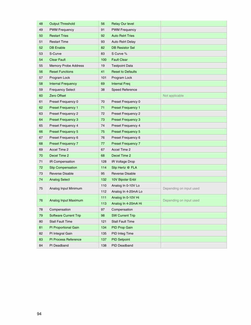
94
48 Output Threshold 56 Relay Our level
49 PWM Frequency 91 PWM Frequency
50 Restart Tries 92 Auto Rstrt Tries
51 Restart Time 93 Auto Rstrt Delay
52 DB Enable 82 DB Resistor Sel
53 S-Curve 83 S Curve %
54 Clear Fault 100 Fault Clear
55 Memory Probe Address 19 Testpoint Data
56 Reset Functions 41 Reset to Defaults
57 Program Lock 101 Program Lock
58 Internal Frequency 69 Internal Freq
59 Frequency Select 38 Speed Reference
60 Zero Offset Not applicable
61 Preset Frequency 0 70 Preset Frequency 0
62 Preset Frequency 1 71 Preset Frequency 1
63 Preset Frequency 2 72 Preset Frequency 2
64 Preset Frequency 3 73 Preset Frequency 3
65 Preset Frequency 4 74 Preset Frequency 4
66 Preset Frequency 5 75 Preset Frequency 5
67 Preset Frequency 6 76 Preset Frequency 6
68 Preset Frequency 7 77 Preset Frequency 7
69 Accel Time 2 67 Accel Time 2
70 Decel Time 2 68 Decel Time 2
71 IR Compensation 128 IR Voltage Drop
72 Slip Compensation 114 Slip Hertz @ FLA
73 Reverse Disable 95 Reverse Disable
74 Analog Select 132 10V Bipolar Enbl
110 Analog In 0-10V Lo 75 Analog Input Minimum
112 Analog In 4-20mA Lo Depending on input used
111 Analog In 0-10V Hi 76 Analog Input Maximum
113 Analog In 4-20mA Hi Depending on input used
78 Compensation 97 Compensation
79 Software Current Trip 98 SW Current Trip
80 Stall Fault Time 121 Stall Fault Time
81 PI Proportional Gain 134 PID Prop Gain
82 PI Integral Gain 135 PID Integ Time
83 PI Process Reference 137 PID Setpoint
84 PI Deadband 138 PID Deadband

95
Notes:

Drive Explorer, DriveExecutive, SSC, PowerFlex and Rockwell Automation are trademarks of Rockwell Automation, Inc Trademarks not belonging to Rockwell Automation are property of their respective companies.
Publication DRIVES-AP005A-EN-E – April 2009Copyright©2009 Rockwell Automation, Inc. All rights Reserved. Printed in USA.