algorithms for test generation and fault simulation of path delay faults in logic circuits
TRANSCRIPT

ALGORITHMS FOR TEST GENERATION AND
FAULT SIMULATION OF PATH DELAY FAULTS IN
LOGIC CIRCUITS
A Thesis
Submitted For the Degree of
Doctor of Philosophy
in the Faculty of Engineering
by
ANANTA KUMAR MAJHI
Department of Electrical Communication Engineering
INDIAN INSTITUTE OF SCIENCE
BANGALORE � ��� ���� INDIA
NOVEMBER ��

To
Bhai

Perfection is the goal of human life� but human e�orts are limited� Happiness does not
come merely through human endeavour� but comes through grace� Blessed are those who
have the grace of both God and master�
� Swami Rama

i
Acknowledgments
It gives me immense pleasure to sincerely thank every one who helped me in various
ways to complete this dissertation� First and foremost� I bow before the Lord Almighty
with a grateful heart� for His blessings which have made me what I am�
I express my deep sense of gratitude to my research supervisor Dr� James Jacob of
the ECE Department� He has been an excellent teacher� counseller� and guide to me and
has given me continual encouragement and wise guidance throughout the course of my
research work� I am also indebted to him and his family for their personal care� love and
understanding during many di�cult times�
I place on record my heartfelt gratitude to my research co�supervisor Prof� L� M�
Patnaik of the CSA Department� for his encouragement� moral support and valuable
suggestions� I am obliged to him not only for providing the computing facilities in Micro�
processor Applications Laboratory� but also for his personal care and fatherly guidance
which will always be remembered and treasured by me�
My heartfelt thanks to Dr� Vishwani D� Agrawal of the AT�T Bell Labs� USA�
for acting as an uno�cial research co�supervisor by always being there for me with his
valuable advice� suggestions� keen interest and encouragement during the entire course
of this work� His comments and suggestions have greatly helped me in improving my
thinking� presenting and writing skills� I thank him also for providing me the most recent
pre�prints and publications� and for having gone through the entire manuscript�
I would like to thank Prof� V� U� Reddy� past Chairman and Prof� A� Selvarajan�
present Chairman of the ECE Department and Prof� N� Balakrishnan� the Chairman of
SERC� for providing the �nancial assistance and necessary computing facilities for my
research work� I must also thank Prof� A� Kumar and Prof� T� S� Vedavathy for allowing
me to use their laboratory facilities during the initial period of my research career and
also for their love and concern over the years�
I have greatly bene�ted by the scholarly advice and suggestions from Dr� M� K�
Srinivas� Rutgers Univ�� USA� Pradip Mandal� Jacob Augustine� and P� R� Sureshkumar�

ii
I thank them for their friendship and encouragement during my research work� I would
also like to thank Dr� Srinivas Patil� Dr� Ankan Pramanick� Dr� Ira Pramanick and Dr�
L� N� Reddy� all of IBM� USA� and Keerthi Heragu of Univ� of Illinois� USA� for providing
me copies of their theses and recent publications in the area of my work�
IISc has been a stimulating environment especially because of my loving friends� Ani�
mesh� Ratikanta� Lochan� Purna� Manoj� Prasant� Saroj� Barada� Krutibas� Himansu� Ni�
raj� Venkatesh� Rajendra� Raghu� Pradipta� Dillip� Pratap� Chidananda� Subhra� Radha�
Gowri� Nanda� Namita� Shorey� Prem� Sai� Mala and others� They have truly shared
many a lighter moment and made my life enjoyable during my stay on the campus� My
special thanks to Animesh� for being always with me in pain and pleasure and sharing
my feelings at my monotonous moments�
I am especially grateful to Biswajit� Biswamohan� Moharana and family� Rajesh and
family� Rout and family� for their love and concern as a younger brother and for making
my stay comfortable in Bangalore� Uninvited appearances in their houses on various
occasions will always be remembered by me�
It is my pleasure to thank Chandramouli Mahadevan� Project Manager� Product
Engineering Division� Texas Instruments �India�� Bangalore� for his kind help and un�
derstanding during the �nal phase of the work� Life is always cheerful in TII due to
friends like Balajee� SriVidhya� Debaleena� Baskar� Swagata� Swathi� Vinayak� Saraja�
RSR� Palani� and Prakash� The �nancial assistance from Texas Instruments �India� for
printing and xeroxing the �nal manuscript is greatly acknowledged�
Finally� words cannot express my feelings of gratitude to my beloved mother� uncle�
and other family members� for their unwavering encouragement� moral support and sac�
ri�ce� without which this work would not have been completed� Their love and blessings
were a perpetual source of inspiration to me�
Ananta
iii
Abstract
Ascertaining correct operation of digital logic circuits requires veri�cation of functional
behavior as well as correct operation at desired clock speed� The maximum allowable clock
rate in a digital circuit is determined by the propagation delays of the combinational logic
network between latches� If the delay of the manufactured network exceeds speci�cations
due to some physical defects or process variations� unstabilized and possibly incorrect logic
values may be latched in memory elements� Delay fault testing can be used to ensure that
manufactured digital circuits meet their timing speci�cations� In this thesis� we present
novel and e�cient algorithms for test generation and fault simulation of path delay faults
in combinational logic circuits�
We have developed a novel delay fault simulator for combinational logic circuits
which is capable of simultaneously analyzing both robust and nonrobust tests for path
delay faults� Only a simple binary logic is used instead of the multi�valued algebra as
is used in most existing simulators� A rule based approach is developed to identify all
robust and nonrobust paths tested by a two�pattern test� while backtracing from primary
outputs to primary inputs in a depth��rst manner� Rules identify probable glitches as
they propagate through the circuit� and thus determine when a test becomes nonrobust�
Experimental results for benchmark circuits determine the performance of the simulator
for deterministic as well as random test vectors� For coverage� all path delay faults are
implicitly considered�
We have also developed an e�cient automatic test generation algorithm for path
delay faults in combinational circuits� To facilitate simultaneous consideration of robust
and nonrobust tests� we employ a ��value logic system� Once a robust test is found
for a path with a given transition� our algorithm derives another test for the opposite
transition with minimal extra e�ort� The derived test in most cases is either a robust or
nonrobust test for the same path� An e�cient multiple backtrace procedure is employed
for satisfying the test generation objectives� A path selection method is proposed which
covers all lines in the logic circuit by the longest as well as the shortest possible paths

iv
through them� The fault simulator� integrated with the test generation system� gives
information on robust and nonrobust detection of faults either from a given target set
or all path faults� Experimental results on several benchmark circuits substantiate the
e�ciency of our algorithm� A comparison with other published results is given�
We propose a new coverage metric and a two�pass test generation method for delay
faults in combinational circuits� The coverage metric termed as line delay fault coverage
considers two delay faults on paths passing through each line in the circuit� one for the
rising transition and the other for the falling transition� However� the test criterion is
di�erent from that of the slow�to�rise and slow�to�fall transition faults� The new test�
called line delay test� is a path delay test for the longest robustly testable path� producing
a given transition on the target line� The maximum number of tests �and faults� is limited
to twice the number of lines� Using a two�pass test generation procedure� we begin with
a minimal set of longest paths covering all lines and generate tests for them� Fault
simulation is used to determine the line delay fault coverage� The second pass considers
those lines for which line delay tests could not be generated in the rst pass� and attempts
to generate robust tests for successively shorter paths through these lines� until a test for
the longest robustly testable path is found� We present a theorem stating that a redundant
stuck�at fault makes all path delay faults involving that faulty line untestable for either
a rising or falling transition depending on the type of the stuck�at fault� The use of this
theorem considerably reduces the e�ort of delay test generation� An implementation of
our algorithm achieved very high �� ��� line delay coverage e�ciency for most of the
benchmark circuits�
We hope that the novel ideas and algorithms proposed in this thesis will nd appli�
cation in the development of e�cient CAD tools for delay fault testing and simulation
of real life VLSI circuits� The new delay fault coverage metric has the advantages of
reduced complexity and high coverage e�ciency� We discuss its limitations with respect
to the conventional path delay fault model� Future experimental work should establish
the validity of our fault coverage metric�

Contents
� Introduction �
��� Design and Test of Integrated Circuits � � � � � � � � � � � � � � � � � � � � �
��� Delay Fault Testing � � � � � � � � � � � � � � � � � � � � � � � � � � � � � � � �
��� Why Delay Fault Testing� � � � � � � � � � � � � � � � � � � � � � � � � � � � �
��� Contribution of the Thesis � � � � � � � � � � � � � � � � � � � � � � � � � � � �
��� Organization of the Thesis � � � � � � � � � � � � � � � � � � � � � � � � � � �
� Prior Work ��
��� Delay Fault Models � � � � � � � � � � � � � � � � � � � � � � � � � � � � � � � �
����� Transition Fault Model � � � � � � � � � � � � � � � � � � � � � � � � � ��
����� Gate Delay Fault Model � � � � � � � � � � � � � � � � � � � � � � � � ��
����� Path Delay Fault Model � � � � � � � � � � � � � � � � � � � � � � � � ��
��� Prior Work on Path Delay Fault Simulation � � � � � � � � � � � � � � � � � ��
����� Path Delay Fault Simulation by Logic Value Propagation � � � � � � ��
����� Parallel Pattern Fault Simulation of Path Delay Faults � � � � � � � ��
����� Non Enumerative Estimation of Path Delay Fault Coverage � � � � �
����� Fault Coverage Estimation by Test Vector Sampling � � � � � � � � � �
����� Delay Fault Coverage Estimation by Selective Path Search � � � � � ��
����� Exact Path Delay Fault Coverage Estimation � � � � � � � � � � � � ��
����� SPADES� A Path Delay Fault Simulator for Sequential Circuits � � ��
��� Prior Work on Test Generation for Path Delay Faults � � � � � � � � � � � � ��
v

vi Contents
����� Test Generation for Path Delay Faults Using PODEM � � � � � � � ��
����� DYNAMITE � � � � � � � � � � � � � � � � � � � � � � � � � � � � � � ��
����� Delay Fault Testing Using Boolean Expressions � � � � � � � � � � � ��
����� NEST� NonEnumerative Test Generation Method for Path Delay
Faults � � � � � � � � � � � � � � � � � � � � � � � � � � � � � � � � � � ��
����� Compact Delay Tests by Multiple Path Activation � � � � � � � � � � �
���� RESIST� Recursive Test Generation for Path Delay Faults � � � � � ��
����� Test Generation for Path Delay Faults in NonScan Sequential Circuits ��
��� Conclusion � � � � � � � � � � � � � � � � � � � � � � � � � � � � � � � � � � � � �
� Path Delay Fault Simulation Using Binary Logic ��
��� Introduction � � � � � � � � � � � � � � � � � � � � � � � � � � � � � � � � � � � ��
��� Theoretical Background and Basic De�nitions � � � � � � � � � � � � � � � � ��
����� Hardware Model and Clock Timings � � � � � � � � � � � � � � � � � ��
����� Robust and Nonrobust Paths � � � � � � � � � � � � � � � � � � � � � ��
����� Sensitivity and Gate Evaluation � � � � � � � � � � � � � � � � � � � � �
��� Path Delay Fault Simulation Using Binary Logic � � � � � � � � � � � � � � � �
��� Glitch Generation and Propagation � � � � � � � � � � � � � � � � � � � � � � ��
����� Glitch Generation � � � � � � � � � � � � � � � � � � � � � � � � � � � � �
����� Glitch Propagation � � � � � � � � � � � � � � � � � � � � � � � � � � � ��
��� Backtracing for Robust and Nonrobust Paths � � � � � � � � � � � � � � � � ��
����� Rules for Evaluating the Inputs of a Robust Gate � � � � � � � � � � ��
����� Rules for Evaluating the Inputs of a Nonrobust Gate � � � � � � � � ��
����� Rule for Evaluating the Input of an IS Gate � � � � � � � � � � � � � �
�� Simulation Results � � � � � � � � � � � � � � � � � � � � � � � � � � � � � � � ��
��� Conclusion � � � � � � � � � � � � � � � � � � � � � � � � � � � � � � � � � � � � ��
� An E�cient Automatic Test Generation System for Path Delay Faults
in Combinational Circuits ��
��� Introduction � � � � � � � � � � � � � � � � � � � � � � � � � � � � � � � � � � � �

vii
��� A ��Value Logic System � � � � � � � � � � � � � � � � � � � � � � � � � � � � ��
���� Derivation of ��Value Logic � � � � � � � � � � � � � � � � � � � � � � ��
�� Path Selection � � � � � � � � � � � � � � � � � � � � � � � � � � � � � � � � � � �
��� Test Generation � � � � � � � � � � � � � � � � � � � � � � � � � � � � � � � � � ��
���� Procedure for Test Generation � � � � � � � � � � � � � � � � � � � � � ��
����� Robust�Nonrobust Test for Opposite Transition � � � � � � � � � � � �
��� Experimental Benchmark Results � � � � � � � � � � � � � � � � � � � � � � � �
��� Conclusion � � � � � � � � � � � � � � � � � � � � � � � � � � � � � � � � � � � � �
� Line Delay Fault Model and Its Coverage ��
�� Introduction � � � � � � � � � � � � � � � � � � � � � � � � � � � � � � � � � � �
��� Line Delay Tests and Coverage Metric � � � � � � � � � � � � � � � � � � � � �
�� Two�Pass Test Generation � � � � � � � � � � � � � � � � � � � � � � � � � � �
��� N �Longest Path Selection � � � � � � � � � � � � � � � � � � � � � � � � � � � �
��� Elimination of Untestable Path Faults � � � � � � � � � � � � � � � � � � � �
��� Experimental Results � � � � � � � � � � � � � � � � � � � � � � � � � � � � � � ��
��� Limitations of the Fault Model � � � � � � � � � � � � � � � � � � � � � � � � �
�� Conclusion � � � � � � � � � � � � � � � � � � � � � � � � � � � � � � � � � � � � ��
� Conclusions ��
�� Summary of Work Presented � � � � � � � � � � � � � � � � � � � � � � � � � � �
��� Future Work � � � � � � � � � � � � � � � � � � � � � � � � � � � � � � � � � � � ��
Bibliography ���

Good manners without sincerity are like a beautiful dead lady� Straightforwardness
without civility is like a surgeon�s knife� e�ective but unpleasant� Candour with courtsey
is helpful and admirable�
� Sri Yukteswar

List of Figures
��� Hardware model and clock timings � � � � � � � � � � � � � � � � � � � � � � �
��� Example of a fault that requires knowledge of circuit delays � � � � � � � � ��
��� Example of robust and nonrobust tests � � � � � � � � � � � � � � � � � � � � ��
��� Examples of robust and nonrobust paths � � � � � � � � � � � � � � � � � � � ��
��� Evaluation of gate sensitivity� CO and NC inputs � � � � � � � � � � � � � � ��
��� Glitch generation � � � � � � � � � � � � � � � � � � � � � � � � � � � � � � � � �
�� Examples of glitch generation � � � � � � � � � � � � � � � � � � � � � � � � � ��
��� Glitch propagation � � � � � � � � � � � � � � � � � � � � � � � � � � � � � � � �
��� Example illustrating glitch generation and propagation � � � � � � � � � � � �
��� Robust and nonrobust inputs of a robust gate � � � � � � � � � � � � � � � � �
�� Nonrobust inputs of a nonrobust gate � � � � � � � � � � � � � � � � � � � � �
��� Example of robustly and nonrobustly tested paths � � � � � � � � � � � � � � �
�� Proposed � value logic � � � � � � � � � � � � � � � � � � � � � � � � � � � � � �
�� Examples of glitch generation � � � � � � � � � � � � � � � � � � � � � � � � � ��
�� Glitch causing a nonrobust test � � � � � � � � � � � � � � � � � � � � � � � � ��
� Example of path selection � � � � � � � � � � � � � � � � � � � � � � � � � � � ��
�� Example of con�ict at a stem � � � � � � � � � � � � � � � � � � � � � � � � � �
�� Pseudo code for the test generation algorithm � � � � � � � � � � � � � � � � ��
�� Test generation �Example ��� � � � � � � � � � � � � � � � � � � � � � � � � � ��
� Derivation of test for opposite transition �Example ��� � � � � � � � � � � � ��
ix
x List of Figures
��� Nonrobust test derived from robust test �Example ���� � � � � � � � � � � � ��
� Test generation for longest path through line � � � � � � � � � � � � � � � � � �
�� Test generation for second longest path through line � � � � � � � � � � � � � ��
�� Elimination of untestable path delay faults � � � � � � � � � � � � � � � � � � �
�� Limitation of the fault model � � � � � � � � � � � � � � � � � � � � � � � � � ��

List of Tables
��� Number of possible physical paths� PIs� POs� and levels � � � � � � � � � � � ��
��� Test generation results � � � � � � � � � � � � � � � � � � � � � � � � � � � � � ��
��� Path delay fault simulation results � � � � � � � � � � � � � � � � � � � � � � � ��
��� Overall statistics � � � � � � � � � � � � � � � � � � � � � � � � � � � � � � � � ��
��� Path delay fault simulation results for ISCAS� circuits � � � � � � � � � � ��
��� Enumeration of logic states � � � � � � � � � � � � � � � � � � � � � � � � � � ��
��� Signal value representation � � � � � � � � � � � � � � � � � � � � � � � � � � � ��
��� Longest path selection � � � � � � � � � � � � � � � � � � � � � � � � � � � � � ��
��� Delay test results for ISCAS� benchmarks � � � � � � � � � � � � � � � � � �
��� Comparison with other results � � � � � � � � � � � � � � � � � � � � � � � � � �
��� Test results for scan�hold versions of ISCAS� benchmarks � � � � � � � �
��� Two�pass test generation results for ISCAS benchmark circuits � � � � � � � ��
��� Statistics for line delay fault e�ciency � � � � � � � � � � � � � � � � � � � � ��
xi

By three methods we may learn wisdom� First� by re�ection� which is noblest� second� by
imitation� which is easiest� and third by experience� which is the bitterest�
� Confucius

Chapter �
Introduction
The primary objective of this thesis is to develop e�cient algorithms for test generation
and fault simulation of path delay faults in combinational logic circuits� We present a
novel path delay fault simulator using binary logic rather than using the multi�valued
logic as presented in most of the literature� An e�cient automatic test generation system
for path delay faults in combinational logic circuits is developed which employs a new
��value logic system for generating robust and nonrobust tests simultaneously� A new
coverage metric called �line delay fault coverage� is proposed for path delay faults and a
two�pass test generation method is developed to obtain almost � line delay coverage
e�ciency�
In this chapter� we provide a brief background of design and test of integrated cir�
cuits � � and the motivation for the research reported in this thesis� Major contributions
of the thesis are summarized and the organization of the thesis is outlined at the end of
this chapter�
��� Design and Test of Integrated Circuits
Rapid advances in integrated circuit technology have made it possible to fabricate digital
circuits with a very large number of devices on a single chip� Very Large Scale Integration
�VLSI� is the fabrication of millions of components and interconnections at once by a
�
� Chapter �� Introduction
common set of manufacturing steps� Its advantages are reduced system cost� better
performance� and greater reliability� These advantages would be lost unless VLSI devices
can be economically tested� The testing process detects the physical defects produced
during fabrication of a VLSI chip� Testing is an experiment in which the system under
test is exercised and its resulting response is analyzed to ascertain the correct behavior�
If an incorrect behavior is detected� the second goal of the testing experiment may be
to diagnose� or to locate� the cause of misbehavior� Diagnosis assumes knowledge of the
internal structure of the system under test�
Manufacturing of a product consists of fabrication and testing� Design and test
development precede manufacture� While design is a synthesis of manufacturable details�
test development speci�es the test data and details of the testing procedure� Design links
the abstract speci�cations to the physical device through a synthesis or assembly of known
parts and generates data necessary to drive the equipment that physically produces the
assembly� Veri�cation� consisting of analysis and simulation� checks correctness of the
design� The correctness of the fabricated device is determined through testing� Thus� in
order to produce a correctly working device� both design and test data are necessary�
In any IC manufacturing process physical defects are almost invariably introduced�
No manufacturing process can guarantee ���� yield and� therefore� some circuits are
bound to have defects� Typical defects include shorts between lines� breaks in conducting
paths� missing devices� pinholes in the oxide layer� threshold voltage shift due to ionic
contamination or improper doping� surface defects due to dust particles� etc� The types
and quantity of defects depend on the variability of process parameters� In general� the
larger the circuit is in terms of chip area� the greater is the chance of having a defect�
It is necessary to separate the bad circuits from the good ones during production as
well as during operation� From an economic viewpoint� the cost of identifying a faulty
component during its life cycle is lowest before it is packaged� This cost increases rapidly
as the component becomes a part of larger and larger systems� Therefore� testing is a
very important aspect of any VLSI manufacturing system�
The testing process involves the application of a sequence of input stimuli� known as

Chapter �� Introduction �
test vectors� to the circuit and a comparison of the circuit response with a pre�computed
expected response� Test vectors are applied to the circuit using an automatic test equip�
ment �ATE�� Any discrepancy in the output response indicates the presence of a fault�
The faults in digital circuits can be classi�ed as logic or parametric faults� A logic fault
is one which causes the logic function of the circuit on an output signal to be changed to
some incorrect function� Parametric faults alter the magnitude of the circuit parameters
causing changes in speed of operation or the levels of currents and voltages� In this thesis�
we focus only on one type of parametric faults� particularly delay faults� which can cause
timing related failures in a circuit�
Test Generation for a VLSI device involves the generation of test vectors to detect
failures� An important issue is the fault model used in test generation� Physical defects
are often modeled as logic faults� This makes the problem of fault analysis independent of
the technology� In addition� tests derived for logic faults may be useful for many physical
faults whose e�ect on the circuit behavior is not well understood or is too complex to be
analyzed� The main requirement for the fault model is that the model should capture
the change in functionality caused by most of the commonly occurring physical defects in
the circuit� Also� the complexity of test generation depends on the fault model and the
circuit representation� The lowest level for a VLSI device is the layout� Test generation
complexity for faults in the geometrical structure at this level is very high� However� it is
possible to consider actual defects like shorts and bridging between conductors� On the
other hand� the test generation complexity is reduced if we model faults at the logic gate
or even higher Boolean function levels� The fault model at these levels may not always
be a true representation of the physical defects� Realistic and higher level fault models
are important areas of research� Some popular fault models targeted by automatic test
pattern generation �ATPG� are the stuck�at fault model� the bridging fault model� the
CMOS stuck�open fault model� and various delay fault models� It is possible that more
than one fault occur in a circuit� However� the single fault assumption is popular as the
total number of multiple faults in a circuit is too large to be considered explicitly� and
tests generated for single faults frequently detect a large numbers of multiple faults� As

� Chapter �� Introduction
di�erent fault models represent di�erent physical defects� it may be necessary to perform
test generation for various fault models and derive tests in order to maximize the product
reliability�
A normal requirement for test vectors is that they detect a very high fraction of the
modeled faults� The detected fraction of the faults is called the fault coverage and it
is determined by the process of fault simulation� Fault simulation involves �nding the
fault�free output response and the set of modeled faults that produce a response di�erent
from the fault�free response� Fault simulation is widely employed to grade the quality
of a given set of tests and is useful to speed up ATPG by avoiding test generation for
those faults already detected by a generated test� Fault simulation is also useful for the
construction of fault dictionaries which help in fault diagnosis� A variety of techniques
for fault simulation have been developed ���
��� Delay Fault Testing
Ascertaining correct operation of digital logic circuits requires veri�cation of functional
behavior as well as correct operation at the rated clock speed� Research on methods to
model failures that a�ect functional behavior and methods to detect these modeled faults
has been extensively reported �� However� it is equally important to insure that the
manufactured circuits meet their timing speci�cations� The maximum allowable clock
rate in a digital circuit is determined by the propagation delays of the combinational
logic network between the latches� If the delay of the manufactured network exceeds
speci�cations� unstabilized and possibly incorrect logic values may be latched in �ip��ops
or produced at outputs� Failures causing logic circuits to malfunction at desired clock
rates� or not meet timing speci�cations are currently receiving much attention� Such
failures are modeled as delay faults� The objective of delay testing is to guarantee that
the circuit operates without any malfunction at the speci�ed clock rate� The use of delay
fault models in VLSI test generation is currently gaining acceptance in the industry�
Recent studies at IBM have shown that the application of a delay fault tests can raise the

Chapter �� Introduction �
SPQL �Shipped Parts Quality Level� by an order of magnitude �����
��� Why Delay Fault Testing�
Digital system designers have traditionally maximized the frequency of system clocks in
order to obtain the highest performance from a hardware unit� The maximum allowable
clock rates are determined by the propagation delays of the combinational logic network
between latches� A change in the logic value at any network primary input �PI� may
propagate along one or more paths through the network to the primary output �PO��
Consider the circuit under test shown in Figure ���� Let DPi be the propagation delay
associated with any path i in the logic network�
tT
2t1t0t
CClock
CClock
2
1
T
2C1CCOMBINATIONAL LOGIC BLOCK
Output is sampledis loaded2Vis Loaded1V
2V 1V
0
1
1
0
0
1
0
1
LATCHOUTPUT
LATCHINPUT
c
Figure ��� Hardware model and clock timings

� Chapter �� Introduction
In practice� logic designers must calculate the maximum path delay DPmax in order
to specify a clocking rate� In Figure ���� during the normal operation of the circuit�
the input clock C� is the same as the output clock C� and the period �Tc� of C� and
C� corresponds to the system clock� This period should be greater than the maximum
propagation delay of any path DPmax in the circuit� However� during testing for delay
faults� we use two separate test clocks� C� and C�� running at the same frequency but
at a speed slower than the normal system clock� Thus� the period of test clocks� Tt� is
longer than Tc� The two test clocks are skewed by the amount Tc� The activation of
the output clock C� must follow the activation of the input clock C� by at least DPmax
time units �i�e�� Tc � t� � t� � DPmax�� If the output clock is activated sooner� then
unstabilized and possibly incorrect logic values may be latched at the output latches�
When the logic network is manufactured� the actual gate delays may not conform to
manufacturing speci�cations� Due to delay faults� the actual DPmax of a manufactured
network can exceed the DPmax predicted by the logic designer� As the clocking rate is
based on the predicted DPmax� the faulty network may not operate correctly� Since delay
faults do not alter the logic function realized by a circuit and since the tests for stuckat
faults are normally applied at a slow clock rate� they are inadequate for detecting delay
faults� Special twopattern test vectors are required for detecting delay faults�
The hardware model used in delay fault testing has been shown in Figure ���� Here
the vector pair � V�� V� � constitutes a delay test and signals C� and C� are used to
clock the input and output latches� respectively� At time t�� an initializing input vector
V� is applied� and the circuit is allowed to stabilize under input V�� At time t�� the
propagation vector V� is applied� and the outputs are sampled at time t�� where �t� � t��
is the intended time interval between the input and output clocks� called the clock period�
or clock interval Tc�
For verifying that the circuit meets timing requirements we must exhaustively test
for all patternpairs� i�e�� apply all pairs of inputs � V�� V� � under the above condition�
and verify that the expected values under V� are always obtained at the output latches
at time t�� However� for the circuits having n inputs� the total number of patternpairs

Chapter �� Introduction �
required will be ��n���n � ��� which is of the order ��n� This will be an astronomical
number even for moderately large values of n inputs� Thus� exhaustive testing is quite
impractical for delay faults� Hence� one has to derive suitable and reasonable delay fault
models and devise algorithms that can generate tests for modeled faults� Various fault
models used in delay fault testing and a survey of existing algorithms for test generation
and fault simulation are presented in Chapter ��
��� Contribution of the Thesis
We propose new and e�cient methods for delay test generation and fault simulation of
path delay faults in combinational logic circuits� The major contributions of this thesis
are
�� A new rule based path delay fault simulation algorithm for combinational circuits
employing twovalued logic simulation ��� �
�� An e�cient test generation algorithm for path delay faults incorporating multiple
backtrace and several novel features ��� �
�� A new coverage metric for path delay fault testing that alleviates the problems of
generally low path delay fault coverage and an astronomically large number of paths�
A two pass test generation approach achieves high fault e�ciency ���� �� �
We have developed a novel path delay fault simulator for combinational logic circuits
which is capable of detecting both robustly and nonrobustly tested paths simultaneously�
Simple binary logic is used in place of the more complex multiplevalued logic as used in
most of the fault simulators presented in the literature� This contributes to the reduction
of the overall complexity of the algorithm� The twovalued algebra proposed in this thesis
is simpler� though not necessarily faster than the multivalued algebras� A rule based
approach has been developed which identi�es all robust and nonrobust paths tested by a
twopattern test� while backtracing from primary outputs to primary inputs in a depth
�rst manner� Additional rules are developed to �nd probable glitches and to determine

� Chapter �� Introduction
how they propagate through the circuit� which enables the identi�cation of nonrobust
paths� Experimental results for several ISCAS��� and scan�hold versions of ISCAS���
benchmark circuits are given�
We have developed a versatile and ecient automatic test pattern generation system
for path delay faults in combinational logic circuits� To facilitate a simultaneous con
sideration of robust and nonrobust tests� we have devised a new �value logic system�
Once a robust test is found for some path with a given transition� our algorithm derives
another test with minimal extra e�ort� The derived test in most cases is either a robust
or nonrobust test for the same path with the opposite transition� We employ a multiple
backtrace procedure for satisfying the test generation objectives� We also use a path
selection method which covers all lines in the logic circuit by the longest and shortest
possible paths through them �� �� We have integrated our fault simulator with this test
generator to determine all robustly and nonrobustly detected faults from the targeted
path faults as well as from all possible path faults in the circuit� Experimental results
on several ISCAS��� and scan�hold versions of ISCAS��� benchmark circuits substantiate
the eciency of our algorithm in comparison to other published results�
We propose a practical coverage metric called �line delay fault coverage� and a two
pass test generation method for path delay faults in combinational logic circuits� The
coverage is measured for each line with a rising and a falling transition� The new test�
called a �line delay test�� is a robust path delay test for the longest sensitizable path
producing a given transition on the target line� One major advantage is that the maximum
number of tests �and faults� is limited to twice the number of lines� Since the fault is tested
along the longest propagation path� the system timing failures caused by the smallest
localized delay defects �spot defects� or the accumulation of distributed delay defects can
be detected� Our model� thus retains many advantages of the transition and gate delay
fault models� while alleviating the major drawback of the path delay model �viz�� too
many paths to be tested and the low fault coverage�� For test generation� in the �rst
pass� we begin with a minimal set of longest paths covering all lines and generate tests
for them� Fault simulation is used to determine the line delay coverage� For uncovered

Chapter �� Introduction �
lines� in the second pass� several paths of successively decreasing length are targeted� We
give a theorem stating that a redundant stuck fault on a line makes all path delay faults
corresponding to paths passing through that line untestable for a particular transition�
The use of this theorem reduces the e�ort of delay test generation� An implementation of
our algorithm achieved very high �� ���� line delay coverage eciency for most of the
ISCAS�� and scan hold versions of ISCAS�� benchmark circuits�
��� Organization of the Thesis
In Chapter �� we survey delay fault models and prior work on test generation and fault
simulation of path delay faults in combinational and sequential logic circuits� In Chapter
�� we present our path delay fault simulator which uses binary logic� Delay fault simu�
lation results for ISCAS�� and scan hold versions of ISCAS�� benchmark circuits are
presented� In Chapter �� we describe an ecient automatic test generation system for
path delay faults in combinational logic circuits� A new ��value logic system is illustrated
for the simultaneous generation of robust and nonrobust tests� Test generation results are
presented for both ISCAS�� and scan hold versions of ISCAS�� benchmark circuits� In
Chapter �� we present the new coverage metric� called �line delay fault coverage� and a
two�pass test generation method for path delay faults in combinational logic circuits� We
have employed the information on redundant stuck�at faults in the circuit� obtained from
a stuck�at fault test generator� to avoid test generation for a large number of untestable
path delay faults and thus have achieved signi�cant savings in computational time by this
novel approach� Results are presented for ISCAS�� and scan hold versions of ISCAS��
benchmark circuits� Finally� in Chapter �� we present a critical review of our work and
suggestions for further research�

Chapter �
Prior Work
This chapter provides the necessary background for the work reported in this thesis� We
�rst discuss various fault models used in delay testing along with their advantages and
limitations� A brief survey of the existing techniques for delay fault simulation and test
generation is also presented�
��� Delay Fault Models
When a logic circuit is found to be free from DC stuck�at faults� it does not imply that the
circuit will operate correctly under actual operating conditions� The operation of digital
circuits is often controlled by periodic clock signals� Correct operation requires that
the propagation of signals in the combinational logic block must be completed within
a clock period� Delay fault testing is used to ascertain that the manufactured digital
circuits meet their timing speci�cations and operate correctly at desired clock rates� A
delay fault causes logic values to change slower than the normal rate which leads to the
malfunctioning of the logic network at the rated speed� Unlike a stuck�at fault� a delay
fault does not a�ect the steady state logical operation of a system� but a�ects the timing
behavior of the system and degrades the overall system performance� In the recent past�
three fault models have been proposed for delay testing� These are described below�
��

Chapter �� Prior Work ��
����� Transition Fault Model
The transition fault model ��� ��� ��� ��� ��� ��� ��� ���� ��� is considered as a logical
model for a defect that delays rising or falling transitions at inputs and outputs of logic
gates� There are two kinds of transition faults� i�e�� slow�to�rise and slow�to�fall� The
slow�to�rise transition fault temporarily behaves like a DC stuck�at�� fault� Likewise� the
slow�to�fall transition fault corresponds to a DC stuck�at�� fault�
A test for a transition fault is a pair of input patterns� one �initialization pattern�
to set up the initial state of a transition and another �propagation pattern� to cause
the appropriate transition and observe its e ects at a primary output� The propagation
pattern is identical to the pattern that detects the corresponding DC stuck�at fault�
The transition fault model has another application� independent of its use as an
idealized model of delay faults� It is well known that stuck�open transistors can induce
sequential behavior in CMOS logic circuits� and testing for such defects can be done only
by applying pairs of patterns� For dynamic CMOS circuits� open transistors that cause
sequential behavior correspond to certain transition faults in Boolean circuits �����
The transition fault coverage is a measure of the e ectiveness of the delay test in
detecting large delay variations� Transition faults are a special case of gate delay faults
because the delay due to the defect is large enough to cause a logical failure when propa�
gated along any path through the site of the fault� The main drawback of this model is
the assumption of large gate delay faults ����� Also� it is di�cult to tell how small a delay
fault can be� before it is not detectable� In practice� delay variations tend to be distributed
over many circuit elements� Thus� many small gate delay faults� each undetectable as a
transition fault� can give rise to a large path delay fault�
����� Gate Delay Fault Model
A quantitative model for delay faults� de�ned as the gate delay fault� was �rst introduced
by Carter et al� ��� In this model� it is assumed that delays through the logic gates
are known with some precision� The characteristics of likely delay faults �size� location�

�� Chapter �� Prior Work
are also known� The delays through a gate are represented by intervals in this model� A
fault is an added delay of certain size� say �� in the rising or falling transition at a gate
input or output� The set of faults considered includes numerical delay information� An
excessive delay of � nanoseconds at a point is not the same fault as an excessive delay of
� nanoseconds at the same point� Both the path delay fault model �discussed in the next
section� and the transition fault model share the characteristic that precise gate delay
information is not integrated into these models and some potential tests for the particular
circuit under test are excluded� The gate delay fault model overcomes this drawback as
illustrated below ���
Consider the circuit given in Figure ���� where the fault being considered is a slow to
rise delay fault on line B�� To excite this fault we need to apply a �� � transition on B�
The initial and �nal values required at the latch with output B are indicated� The arrows
between the latches indicate the correlation in the scan chain when the �nal pattern is
derived by a one bit shift of the initial pattern� For example� specifying a initial value
of ��� for B forces the same �nal value ��� for C� To propagate the fault to F puts the
requirement of ��� for the �nal value of A� To further propagate the fault to the output H
requires a steady ��� �without any glitch� on G� Since B� already has a �� � transition�
most test generation schemes will attempt to justify a steady ��� on G by setting a steady
��� on E� However� a steady ��� on E results in a con�ict with the values chosen so far as
it requires steady ��� on both inputs to E� Without any knowledge of the circuit delays
one would have to give up at this point� However� the set of latch values indicated is a
test if the AND gate �E� delay is large enough that G has a steady ��� because E does
not fall until after B� has risen�
Given the size of a gate delay fault� most of the recent research in this area has
concentrated on the determination of such fault sizes detected by a given test ��� ��� �����
Given a particular fault of a �xed known size� Carter et al� ��� provide a method to
determine whether a test T detects that fault� This is clearly a painstaking and ine�cient
method� and it would be more desirable to �nd a certain minimum fault size at a fault
site such that given a test T for a fault at the above fault site� T is guaranteed to detect

Chapter �� Prior Work ��
1 1
0 1
1 0
1 1
1 1
0 1
1 0
1 1
B1
B2
A
B
C
D
1 0E
F
G
H
1 0
1 11 0
Figure ���� Example of a fault that requires knowledge of circuit delays
any fault at that site with a magnitude greater than the determined minimum size�
����� Path Delay Fault Model
The path delay fault model was �rst proposed by Smith ������ This model has received
greater attention than the gate delay and transition fault models and has been quite
extensively studied �� �� �� �� �� �� �� �� � � � ��� ��� ��� �����
A considerable amount of research has already been reported on various aspects of test
generation and fault simulation of path delay faults� Our research work mainly considers
e�cient methods for test generation and fault simulation of path delay faults and we
propose a new coverage metric for path delay fault testing in Chapter ��
In path delay fault model any path with a total delay exceeding the system clock
interval is said to have a path delay fault� This is a distributed fault model because
it is associated with an entire path� For each physical path P connecting a primary
input to the primary output of the circuit there are two corresponding delay paths� The
rising path �falling path� is the path traversed by a transition which is initiated as a
rising �falling� transition at the input of path P and changes the direction of transition
whenever it passes through an inverting gate� For convenience we shall refer to a �delay
path� simply as a �path� and denote it as Px when the direction of the transition is

�� Chapter �� Prior Work
immaterial� A path Px is said to have a path delay fault if the propagation delay of the
path is larger than the clock interval Tc as described in the previous chapter� We present
the following de�nition from �����
De�nition ���� Let G be a gate on path P in a logic circuit and let r be an input
to gate G r is called an o��path sensitizing input if r is not on path P �
Robust Tests
The class of robust tests for path delay faults is a very important class of delay fault
detecting tests� We present the following de�nitions and results ����� for combinational
circuits�
De�nition ���� A two pattern test � V�� V� � is called a robust test for a delay
fault on path P if the vector detects that fault independently of all other delays in the
circuit�
It has been shown ����� that a two pattern test � V�� V� � represents a robust test
for path fault on P i�
� it provokes a transition on the primary input at the source of the path�
� it guarantees that all signals on the structural path corresponding to P cannot attain
their �nal values according to V� until the provoked transition reaches them�
Nonrobust Tests
De�nition ��� A two pattern test � V�� V� � is called a nonrobust test for a delay
fault on path P if it detects the fault under the assumption that no other path in the
circuit involving the o� path inputs to P has a delay fault�
A satisfactory de�nition for nonrobust test has not been given in the literature� The
de�nition given by Schulz et al� ����� and several others is based on the early arrival of
the o� path signals� It is possible to �nd an example where a nonrobust test will fail to
detect the fault even if their condition is satis�ed� Therefore we have chosen the above
de�nition which matches that of Gharaybeh et al� �����

Chapter �� Prior Work ��
It has been shown ����� that a two�pattern test � V�� V� � represents a nonrobust
test for a fault on path P � i��
� it provokes a transition on the primary input at the source of the path
� V� causes all o��path sensitizing inputs along the structural path corresponding to P
to assume those non�controlling values that allow the propagation of the transition
from the primary input PI� to primary output PO�
Examples for robust and nonrobust tests are given below
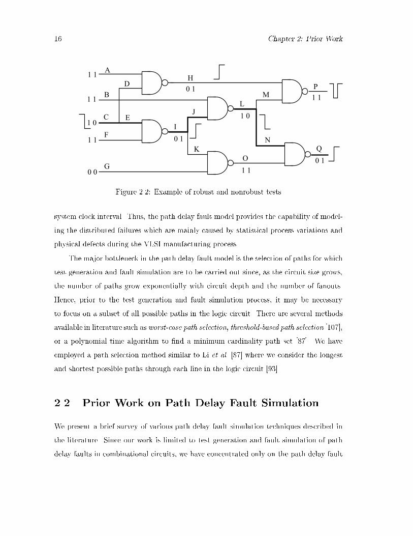
Consider the circuit given in Figure �� The two�pattern test vector consists of the
initialization vector V� � ���� and the propagation vector V� � �� � According to
De�nition ��� this is a robust test for the structural path P� � C�E�I�J�L�N�Q shown
in bold lines�� since all signals on the corresponding path cannot attain their �nal values
unless the provoked transition at input C arrives The same test becomes a nonrobust
test for the structural path P� � C�E�I�J�L�M�P� because an excessive delay in the rising
transition on line H may cause the primary output line P � to have its expected true �nal
logic value ��� at the sampling time� regardless of the delay on path P� Thus� it can lead
to the conclusion that the circuit is fault�free� although there are delay faults on line H
and path P� But if there is no delay fault on line H and when P� has a delay fault� we
will get the faulty logic value � � on the primary output P at the sampling time provided
that the delay fault on P� is not due to a lumped delay defect on the output gate P �
Thus� the above test ful�lls the conditions for a nonrobust test for path P� as stated in
De�nition �� The usefulness of a nonrobust test is limited since it does not guarantee
the detection of a path delay fault independent of other path delays in the circuit
The gate delay and transition fault models described earlier have some inherent draw�
backs They do not model the cumulative e�ect of distributed gate delays along a path
from primary inputs to primary outputs The path delay fault model alleviates this de��
ciency In this model� the delay fault is associated with a physical path and the path is
declared to be free of delay faults only if the transition provoked at the input of the path
propagates to the output through the speci�ed path in less time than the operational
�� Chapter �� Prior Work
A
B
C
D
E
F
G
H
I
J
K
LM
N
O
P
Q
1 0
1 1
1 1
1 1
0 0
0 1
1 0
0 1
1 10 1
1 1
Figure ���� Example of robust and nonrobust tests
system clock interval� Thus� the path delay fault model provides the capability of model�
ing the distributed failures which are mainly caused by statistical process variations and
physical defects during the VLSI manufacturing process�
The major bottleneck in the path delay fault model is the selection of paths for which
test generation and fault simulation are to be carried out since� as the circuit size grows�
the number of paths grow exponentially with circuit depth and the number of fanouts�
Hence� prior to the test generation and fault simulation process� it may be necessary
to focus on a subset of all possible paths in the logic circuit� There are several methods
available in literature such as worst�case path selection� threshold�based path selection ����
or a polynomial time algorithm to �nd a minimum cardinality path set � �� We have
employed a path selection method similar to Li et al� � � where we consider the longest
and shortest possible paths through each line in the logic circuit �����
��� Prior Work on Path Delay Fault Simulation
We present a brief survey of various path delay fault simulation techniques described in
the literature� Since our work is limited to test generation and fault simulation of path
delay faults in combinational circuits� we have concentrated only on the path delay fault

Chapter �� Prior Work ��
model�
����� Path Delay Fault Simulation by Logic Value Propagation
Smith ����� �rst proposed a procedure that identi�es paths which are tested for path delay
faults by a given set of patterns� He used a six�valued logic to describe the state of a signal
in two consecutive patterns� Each value consisted of the ordered pairs s �s p �p �
and ��� The �rst element of each ordered pair was a Boolean or � which represented the
�nal logic value of the signal� The second value was �s� steady� �p� path� or ��� neither
�s� nor �p��� A value �s� indicated that a gate necessarily held a steady value during the
two patterns� This must be true no matter what delays are assumed for the gates of the
network� The value s �s� indicated that the initial and �nal logic values of the signal
were �� and there were no transients hazards� between the two consecutive patterns�
A value �p� indicated that there was at least one path of gates with a value �p� from the
network input to this gate and that the gate output did not change before transitions
have propagated through each path of gates with a value �p� from the network input to
this gate� A value p �p� denoted a falling rising� transition of the signal during the
two consecutive patterns� There may be momentary transitions between the initial and
�nal patterns� A value ��� indicated that it did not meet the criteria for values �s� or �p��
A gate with a value ��� may have none one or many transitions� Its �nal value may or
may not be the same as its initial value� The value � ��� represented a logic value ��
in the �nal pattern of the signal and an unknown X� logic value in the initial pattern�
There may be several transitions between the two consecutive patterns�
The following procedure describes how to identify the set of paths that are robustly
tested for path delay faults independent of other delays by a set of patterns�
Procedure�
�� Generate the next set of initial and �nal values� Assign corresponding values s �s
p or �p to each input of the network�

�� Chapter �� Prior Work
�� Propagate values as per the propagation tables which can be easily derived for each
gate type ������
�� Trace each path in the list of untested paths� Any path with the correct transition
direction and with the value �p on every gate of the path is agged as tested� It is
then removed from the path list�
The main advantage of this method is that a path is tested for path faults independent
of gate delays and the size of any individual gate delay has no e�ect on the delay testing
of the path� Whether or not the delay values of individual gates exceed speci�cations is
irrelevant to this criterion� This fault model is capable of modeling all delay faults of any
size� The execution time is roughly proportional to a linear function of the number of
gates and the number of paths�
����� Parallel Pattern Fault Simulation of Path Delay Faults
Schulz et al� ��� � proposed an accelerated fault simulation for path delay faults� which
applies parallel processing of patterns� A large number of paths cannot be tested under
the restrictive condition of robustness� Using Smiths six�valued algebra� they devised a
four�valued algebra to enable simulation of robust and nonrobust path delay faults�
In order to e�ectively cope with the typically huge number of paths in circuits� they
have employed a highly economical data structure� called the path tree� Its basic idea
consists in storing parts of paths� which are common to many paths from a distinct PI
to POs� only once rather than explicitly carrying them along for each path separately�
Performance results for robust and nonrobust path delay fault simulation of ������ random
pattern pairs for the ISCAS� benchmark circuits have been reported� However� even
with an e�cient data structure� explicit representation of all physical paths can be very
expensive� for example� it takes more than �� MB to store the path tree for circuit c�����

Chapter �� Prior Work ��
����� Non�Enumerative Estimation of Path Delay Fault Cover�
age
Pomeranz and Reddy ����� propose a method to estimate the number of path delay
faults detected by a given test� without enumerating paths� The time complexity of the
algorithm is polynomial in the size of the circuit� The computed estimate is pessimistic�
i�e�� the true fault coverage is greater than the estimated one� As the degree of complexity
of the polynomial is increased� better estimates are obtained� If the degree of polynomial
is allowed to be of the order of number of lines in the circuit instead of being a constant�
the complexity becomes exponential and the exact number of path delay faults detected
is obtained� Three properties are used to allow the fault coverage of path delay faults to
be estimated without enumerating paths�
�� The total number of physical paths in the circuit can be computed in time that is
linear in the number of lines in the circuit� by making one backward pass over the
circuit�
�� Considering a single test pattern� one pass of fault�free logic simulation is required to
determine which lines in the circuit belong to paths whose delay faults are covered
by the test� In this method� the number of paths dened by this subset of lines
can be determined in linear time without enumerating paths� The number of paths
computed equals the number of path delay faults covered by the test�
� Considering an arbitrary test pattern in a given test set� some of the faults detected
by the test are also detected by the preceding tests� Only new faults detected for
the rst time by the test pattern considered should be counted for the purpose of
computing the fault coverage� Circuit lines that are not included in path delay
faults detected by earlier tests are determined� These lines are called new lines�
The number of new path delay faults detected by the test pattern considered can
be pessimistically estimated by counting the number of path delay faults detected
by the test� which include at least one new line� The estimated number of faults

�� Chapter �� Prior Work
can then be added to the number of faults detected earlier to obtain an estimate of
the fault coverage�
An approximation is required to estimate the fault coverage of a test set comprising
more than than one test� Several levels of approximation� with increasing accuracy and
increasing complexity� have been proposed� In all cases� the method remains polynomial
in the number of lines in the circuit� and thus allows even circuits with exorbitant number
of paths to be considered under the path delay fault model� However� using the zero�order
approximation method� the coverages tend to be very pessimistic and have a signi�cant
error as reported by Heragu et al� ���� Also� the method does not give any information
about the detectability of individual faults� which can be used for fault dropping� Heragu
et al� ���� � have proposed further improvements to this method to reduce the estimation
error in fault coverage�
����� Fault Coverage Estimation by Test Vector Sampling
Heragu et al� ��� proposed another approximate technique of estimating fault coverage
in combinational circuits by fault�free simulation of a random sample of the test vector
set� Unlike fault sampling where exact fault simulation is required for the sampled faults
over the entire vector set� in this case� they only determine detection probabilities of all
faults from fault�free simulation of a randomly sampled subset of vectors�
The proposed vector sampling method is applicable to both stuck�at faults and delay
faults� They use a fault sampling technique to determine path delay fault coverages
with respect to all paths� where only a �xed number of sampled paths is considered for
fault coverage computation� Following fault�free simulation of a random sample from the
vector set� they statistically compute controllabilities and observabilities of all faults in
the circuit which are used to predict fault detection probabilities on a randomly selected
vector pair� The detection probabilities for the entire length of the vector set is then
computed and are used to predict the fault coverage�
For F faults� V vectors� and N lines in a circuit� the complexity of their method is
Chapter �� Prior Work ��
O�N� as opposed to O�N � F � V � for a fault simulator and O�N � V � for a random
sampling estimator� The reduction in complexity of fault coverage estimation becomes
very signi�cant in applications like built�in self�test �BIST� where the number of vectors
is typically very large�
����� Delay Fault Coverage Estimation by Selective Path Search
Bose et al� proposed fault simulation algorithms for path delay faults in synchronous
sequential circuits ���� A dynamic path search of only the active paths is devised to
avoid explicit simulation of all path faults� The fault simulator provides both robust and
nonrobust fault coverage� For robust coverage a new update rule �Optimistic Update
Theorem� for state variables is used in which latches are updated with their correct values
provided they are destinations of at least one robustly activated path delay fault ���� This
rule provides a less pessimistic coverage than the earlier method of Chakraborty et al� ���
in which all latches with transition were assumed to have unknown values�
Among the numerous possible paths in a circuit only a few propagate transitions
during any given vector� The number of such paths depends on the previous and current
vectors and is a dynamic property of both the circuit and input vectors� After simulation
of a new vector the algorithm evaluates the highest ranked sensitized path in the subtree
rooted at each node� This information is maintained at each node with the help of a
one�bit propagation �ag called p��ag and an integer identi�er referred to as maxpath�
If p��ag is false then no sensitized path to any output of the combinational logic exists
in the subtree and the value of maxpath is irrelevant� So p��ag is true if a sensitized
path from that node to an output exists� The evaluation of maxpath uses the values of
pathcount at each node of the graph� The computation is done with a depth��rst search�
The complexity of the algorithm is O�n�F � where n is the number of lines the circuit
and F is the number of faults considered� However if for every vector pair a signi�cant
number of paths is sensitized then the complexity of this algorithm can be O�n� �n� in
the worst case due to the possibility of an exponential number of paths in large circuits�

�� Chapter �� Prior Work
Hence� the method may not work well for estimating path delay fault coverage for large
circuits�
����� Exact Path Delay Fault Coverage Estimation
In recent papers� Gharaybeh et al� ���� have presented an e�cient fault simulator� for
path delay faults� that does not involve enumeration of paths� Their method calculates
the exact fault coverage� and identies all tested faults even in circuits with a very large
number of paths� They have presented a new data structure called PathStatus Graph
�PSG�� to e�ciently hold the status of each path delay fault in the circuit� The key to this
e�ciency is in breaking the information into pieces and distributing over the data structure
and in retaining all or part of the reconverging fanout structure of the circuit in the PSG�
Thus� an exponential number of path delay faults can share the same piece of information�
In their implementation� they have used the sixteenvalued algebra � ��� which is e�cient
for simulating single�input change �SIC� patternpairs� They have concentrated on non
robust detection which identies singlytestable �ST� path delay faults � ���
Kapoor ���� has presented an e�cient algorithm to compute exact path delay fault
coverage� In his implementation� a set of consecutively numbered path delay faults has
been represented as a closed interval over a pair of integers� He has described a modied �
� tree data structure to store and manipulate these intervals to keep track of tested faults�
In addition to estimating exact path delay fault coverage� this technique also provides the
ability to e�ciently nd out whether a given path delay fault has been tested�
����� SPADES� A Path Delay Fault Simulator for Sequential
Circuits
Pomeranz et al� ����� proposed a fault simulator for path delay faults in synchronous
sequential circuits� where a test sequence is considered under di�erent combinations of
slow and fast clock cycles �clocking schemes�� The main features of the fault simulator
are as follows� ��� A special path representation scheme is used� which facilitates the step

Chapter �� Prior Work ��
where a detected path fault is compared to the previously detected path faults� to �nd
whether the fault has already been detected by a previous test or the fault coverage has
to be increased� ��� For a given input sequence V and a clocking scheme C containing
a single fast clock cycle� it determines the path delay faults detected by robust and
nonrobust tests� ��� Given an input sequence V � it simulates in parallel all cases of a
di�erent single vector applied with a fast clock� The full fault coverage of a test sequence
of length k� when used with any set of clocking schemes� can be determined by considering
a number of clocking schemes which is linear in the length of the test sequence� instead of
considering all �k possible clocking schemes� �� Given an input sequence� it determines
a minimal number of clocking schemes� each using multiple fast clock cycles� to achieve
the maximum fault coverage� These features maximize the number of faults detected by a
given sequence and minimize the number of clocking schemes with which a test sequence
is applied�
The major drawback of the proposed method is that it assigns unknown values to
o�path latches that have nonsteady signals at their inputs in the previous vector� Such
procedures are pessimistic and predict low fault coverages� They also have an adverse
e�ect on the execution time of fault simulation� especially if the circuit has a large number
of active paths� because a separate analysis of fault e�ect propagation may be necessary
for every active path fault� The situation can be remedied by the optimistic update
theorem of Bose et al� �� as mentioned in Section ������
��� Prior Work on Test Generation for Path Delay
Faults
We now give a brief survey of various test generation techniques which have been developed
for path delay faults in combinational as well as sequential logic circuits� We also discuss
the advantages and limitations of the di�erent approaches�

�� Chapter �� Prior Work
����� Test Generation for Path Delay Faults Using PODEM
Lin and Reddy ���� �rst proposed a PODEM based test generation technique for path
delay faults in combinational circuits� The delay fault test generation algorithm with a
PODEM type mechanization with several heuristics to aid backtracing has been imple
mented and described by Patil and Reddy ��� �� They propose a �vevalued logic system
to facilitate the derivation of robust tests for path delay faults and give necessary and
su�cient conditions for a twopattern test to be a robust test for a given path�
The major advantage of this approach is that the proposed logic system allows spec
i�cation of minimal signal conditions to propagate required transitions along the path
under test� The reduced number of logic symbols leads to more e�cient implementations
in terms of computation time and memory requirements�
����� DYNAMITE
Fuchs et al� ���� proposed a test generation system for path delay faults in combinational
or scanbased circuits named Delay Fault Oriented Automatic Test Generation System
�DYNAMITE�� Their method exploits the bene�cial techniques applied in the automatic
test generation �ATG� system SOCRATES ������ Based upon a ��valued logic for robust
tests and a threevalued logic for nonrobust tests DYNAMITE is capable of generating
tests for path delay faults� Moreover in order to overcome the main disadvantage of
the path delay fault model they introduce a new path sensitization procedure which is
capable of e�ciently identifying large number of path faults as redundant with a single
ATG attempt� If the given subset of paths is not highly testable due to the presence
of many redundant paths DYNAMITE dynamically switches to another subset of paths
and may eventually succeed in generating a test set for all testable path delay faults� The
path tree structure ����� described in Section ����� is used for e�cient storage of paths�
All selected paths are stored in the path tree� A stepwise path sensitization procedure
identi�es sets of redundant path delay faults without enumerating them� This method is
very e�ective in poorly testable circuits but many faults have to be treated separately in

Chapter �� Prior Work ��
those circuits that are highly testable� A limitation of this approach is that the storage of
the path tree is impractical for large circuits� Because of limited memory resources� the
set of all path delay faults must usually be partitioned into many subsets�
����� Delay Fault Testing Using Boolean Expressions
Bhattacharya et al� ��� present a new test generation technique for path delay faults in
scan�hold type circuits� They use reduced ordered binary decision diagrams ROBDDs
to represent Boolean functions implemented by the sub�circuits in a circuit� as well as to
represent the constraints to be satis�ed by the delay fault test� Two faults are considered
for each path in the circuit under test and a pair of constraint functions� corresponding to
the two time frames that constitute a transition� is evaluated for each fault� These con�
straint functions are manipulated to obtain robust tests if they exist otherwise nonrobust
tests are obtained� For circuits amenable to analysis using BDDs� the Boolean algebraic
technique is much faster than existing branch�and�bound algorithms� This approach� how�
ever� requires post processing steps to check for robustness� Since an exhaustive check
may be prohibitively CPU intensive� the method only provides a conservative estimate of
the robust path delay fault coverage�
Chakradhar et al� ���� have employed a four�valued logic in a similar approach when
the constraint function is solved using a transitive closure method�
����� NEST� Non�Enumerative Test Generation Method for Path
Delay Faults
Pomeranz et al� ����� present a test generation method that is based on the procedures
introduced in their fault coverage estimator ����� described in Section ����� and is ca�
pable of generating tests for a large number of path delay faults� without enumerating
paths� The basic idea behind the method is to replace the practically infeasible process
of considering an exponential number of paths with a process that considers single lines�
The authors show that it is possible to detect a large number of path delay faults by

�� Chapter �� Prior Work
propagating transitions robustly through parts of the circuit� without having to enumer�
ate the complete paths through which these transitions are propagated� To make the
method e�ective� subcircuits with a large number of paths� which can be simultaneously
tested� are identi�ed� This is done by using a labeling technique that considers only lines
�and not paths� For every selected subcircuit� test generation objectives are determined�
Once the objectives are satis�ed� a test is obtained that often detects a large number of
path delay faults� A fault simulation method ���� is then used to estimate how many
faults are actually detected�
The major advantage of this approach is that� in contrast to conventional test genera�
tion approaches where speci�c faults are targeted� this method allows circuits with a large
number of detectable path delay faults to be handled� It thus removes the most serious
restriction of the path delay fault model� The drawback of this method� however� is that
though it is e�ective in highly testable circuits� it may fail in those with poor testability�
NEST also provides only a conservative estimate of the robust path delay fault coverage�
����� Compact Delay Tests by Multiple Path Activation
Bose et al� ��� present a test generation algorithm for multiple path tests� The objective
is to generate a compact set of tests that will robustly test all testable path delay faults�
Each test is successively augmented to detect as many path faults as possible� Other
features of the test generator are a PODEM�like branch�and�bound search for test and an
algorithmic selection of secondary target faults for augmenting the tests to cover multiple
faults� The new ideas incorporated in the algorithm are
�� A ���value logic system that represents the signal state in two consecutive vectors�
It has been shown ��� that such a ���value logic system is ideal� This logic system
is complete and puts minimum restrictions on signals for satisfying path activation
requirements�
�� An e�cient path numbering scheme previously developed for path delay fault sim�
ulation ��� ���� ���� is employed to avoid storing the details of paths� which may

Chapter �� Prior Work ��
require enormous memory�
�� A test generation procedure that arbitrarily selects the �rst path and uses the ���
value logic to obtain a test with a minimal set of essential signal assignments� The
logic is further used to �nd the candidate paths that may be testable by augmenting
the present test�
The drawback in this approach is that the fault selection algorithm is heuristic and
does not guarantee that a test will indeed be found by input assignment modi�cation for all
secondary target faults� No consideration is given to the circuit connectivity� However� the
method works well for smaller circuits� whereas for some circuits the number of secondary
backtracks is very large as reported in the results�
In a recent paper ��� Pramanick and Reddy have presented an e�cient method
for multiple path propagation compact tests for delay faults where each test covers many
single path faults�
����� RESIST� Recursive Test Generation for Path Delay Faults
Fuchs et al� � � present RESIST� a recursive test pattern generation algorithm for path
delay fault testing of combinational and scan�based sequential circuits� Five di�erent test
classes are introduced and their properties are discussed� They derive a logic system for
test pattern generation that results in an early recognition of con�icting value assignments�
RESIST uses the derived logic system for each test class for an optimal search strategy�
In contrast to earlier approaches� RESIST exploits the fact that many paths in a circuit
have common subpaths and sensitizes these subpaths only once� thus reducing the number
of value assignments during path sensitization signi�cantly� In addition� the procedure
identi�es large sets of untestable path delay faults without enumerating them�
Reported results show that RESIST is capable of performing test pattern generation
for all path delay faults in ISCAS�� and ISCAS�� benchmark circuits� A comparison
with other test pattern generation systems shows that RESIST is signi�cantly faster than
all previous published methods�

�� Chapter �� Prior Work
����� Test Generation for Path Delay Faults in Non�Scan Se�
quential Circuits
Agrawal et al� ��� developed a new method for generating tests for path delay faults
in synchronous sequential circuits using the sequential circuit test generation program
STEED ����� To generate a test sequence for a path delay fault they augment the netlist
model of the circuit under test with a sequential logic block such that the test for a single
stuck type fault in this block is also a test for the path delay fault in the original circuit�
The added logic consists of a pair of ip�ops and a few logic gates that are driven by the
signals feeding the gates on the paths� A stuck�at fault in this logic is activated and its
e�ect is latched into the destination ip�op of the path only when all signals on the path
are set in the states required for the delay test� The fault e�ect is then propagated to a
primary output� The test sequence for the stuck fault thus performs all three functions
namely initialization path activation and fault propagation for the delay fault�
Given a path and a transition a modi ed circuit is created in which a test for a
speci ed single stuck fault will detect the delay fault� This stuck fault is de ned as
follows�
�� The stuck fault must be activated only when the two path activation vectors have
been applied to the combinational logic� Since the circuit is sequential any initial�
ization vectors also precede path activation vectors�
�� Once the stuck fault is activated its e�ect �D or D� is injected into the destination
ip�ops of the path� This happens at the second path activation vector� Prior to
its activation the stuck fault must not interfere with the normal operation of the
circuit�
�� After the fault e�ect is stored in the destination ip�op the stuck fault must allow
the fault�free function of the circuit during the propagation phase�
Notice that the initialization and propagation phases assume slow clock operation� The
main disadvantage in this approach is that the complexity is rather high which makes it

Chapter �� Prior Work ��
impractical for very large sequential circuits�
Chakraborty et al� ���� propose another method for test generation of path delay
faults in random logic sequential circuits� A new thirteen�valued algebra is employed to
represent logic values in two consecutive time frames and the hazard between them� This
algebra helps in detecting robust and nonrobust tests and hence is useful for path based
delay fault simulation� Three fault models are proposed based on speci�c assumptions
about the initial states of �ip��ops for the vector sequence that propagates the captured
logic value to a primary output� This method of path delay testing in which the clock is
run at rated speed only during the path activation phase simpli�es test generation�
One disadvantage of this approach is that no speci�c criterion is used to select a
combinational path between the source and destination� Hence this method may not be
feasible for large circuits� The experience in their approach indicates that circuits with
poor testability with respect to stuck�at faults� may in fact also have many untestable
paths� The consequences arising from low path delay fault coverage however require
detailed investigation�
The process of test generation under rated clock test application in sequential circuits
is more complex� Recent results have been given by Bose and Agrawal �� �� However
because of the complexity of the problem they were able to give results only for some
smaller benchmark circuits�
Multi�valued algebras are basic to delay testing� These algebras should be minimal
use the smallest number of values� and complete provide all information necessary for
the speci�c problem�� Derivation of such algebras is discussed by Bose et al� �����
��� Conclusion
In this chapter we brie�y discussed the three important delay fault models namely the
transition fault model the gate delay fault model and the path delay fault model� The
advantages and limitations of these fault models were also discussed� Our present work is
con�ned to the path delay fault model which has the advantageous capability of modeling

�� Chapter �� Prior Work
the distributed failures along an entire path� We have also presented a brief survey of
various techniques used for test generation and fault simulation of path delay faults in
combinational as well as sequential circuits� In the following chapters� we will describe
the main contributions of our work� i�e�� the development of e�cient test generation and
fault simulation algorithms for path delay faults in combinational circuits and also a new
line delay fault coverage metric for path delay faults�

Chapter �
Path Delay Fault Simulation Using
Binary Logic
In this chapter� we present a novel path delay fault simulator for combinational logic cir�
cuits� The simulator is capable of detecting both robustly and nonrobustly tested paths
simultaneously� We use binary logic instead of the multiple�valued logic as is used in ex�
isting simulators� The simpler logic contributes to the reduction of the overall complexity
of the algorithm� A rule based approach has been developed which identi�es all robust
and nonrobust paths tested by a two�pattern test using backtracing from POs to PIs in
a depth��rst manner� Rules are also given to �nd probable glitches and to determine
how they propagate through the circuit� thus identifying nonrobust paths� Experimental
results on several ISCAS��� and the scanhold versions of ISCAS�� benchmark circuits
demonstrate the e�ciency of the algorithm�
��� Introduction
There has always been an increasing demand for faster digital systems� The maximum
allowable clock frequency in a synchronous system is determined by the propagation delay
of signals in the combinational network between latches� Due to some physical defects�
statistical process variations or stray capacitances� if the delay of the manufactured net�
�

�� Chapter �� Path Delay Fault Simulation Using Binary Logic
work exceeds speci�cations� there is a chance of unstabilized and possibly incorrect logic
values being latched� Delay fault testing can be used to ascertain that manufactured dig�
ital circuits meet their timing speci�cations and operate correctly at desired clock rates�
Thus� delay fault testing has achieved theoretical and practical importance in the design
of high�speed logic circuits� In this chapter� we have presented a novel path delay fault
simulator for combinational circuits which detects the faulty paths under the application
of two�pattern tests�
We described several delay fault models and their advantages and limitations in the
previous chapter� The path delay fault model is considered for delay fault simulation
and test generation in our present work� In this model� the delay fault is associated with
a physical path in the circuit and the path is declared to be free of delay faults if the
transition provoked at the input propagates to the output through a speci�ed path in less
time than the operational system clock interval�
There is a major bottleneck in selecting paths for which the test generation and fault
simulation are to be carried out� since as the circuit size grows the number of paths can
grow exponentially with circuit depth and the number of fanouts� Hence� prior to the
test generation and fault simulation process� it may be necessary to focus on a subset
of all possible paths in the logic network� There are several methods available in the
literature such as the worst�case path selection� threshold�based path selection ���� and
a polynomial time algorithm to �nd a minimum cardinality path set ���
Multi�valued logic systems are commonly used for test generation and fault simulation
of path delay faults� Smith ���� has proposed a six�valued logic� which identi�es the
paths tested for delay faults independent of the delays of any individual gate in the
network� Schulz et al� �� � have used Smith�s six�valued logic and a modi�ed four�valued
logic for robust and nonrobust detection of path delay faults with parallel processing of
patterns� Bose et al� �� have used Smith�s six�valued algebra for delay fault simulation
of synchronous sequential circuits� Similarly� multiple�valued logic has been used for
the test generation process of the delay faults� e�g�� eleven�valued logic ����� ten�valued
logic ���� ���� and �ve�valued logic ���� ��� The number of logic states used is a factor

Chapter �� Path Delay Fault Simulation Using Binary Logic ��
that determines the time and memory complexity of the algorithms based on them� fewer
logic symbols lead to less complex implementations ����� Hence� we have employed the
simple two�valued logic for path delay fault simulation�
The broad outline of our fault simulation approach is as follows� During eventdriven
logic simulation with respect to the rst vector �initialization vector� of the twopattern
test � V�� V� �� we classify all gate inputs as either controlling �CO� or noncontrolling
�NC� based on their logic values� After evaluating the true logic values with respect to the
second vector �propagation vector�� using the same eventdriven approach� the possibility
of a glitch event at the output of a gate is determined taking both the initialization and
propagation vectors into account� An eventqueue is also maintained for the propagation
of the glitch events from PIs to POs in order to determine the robustness nonrobustness
of a path� Finally� we backtrace from POs to PIs in a depthrst manner based on some
specied rules to trace the faulty paths� Thus� our algorithm detects both robust and
nonrobust paths during the simulation procedure� All paths are counted initially� but no
target path list is generated� Once a path fault is detected by a vector pair� it is added
to the global list of detected faults to keep track of the fault coverage� Thus� all paths in
the circuit are implicitly considered by the fault simulator� The algorithm can be easily
modied to simulate faults for any given list of paths�
��� Theoretical Background and Basic De�nitions
����� Hardware Model and Clock Timings
Unlike a singlepattern test as used for testing a stuckat fault� delay fault testing re
quires a twopattern test� The main objective of delay fault testing is to ensure that the
maximum propagation delay of paths in the circuit is less than the system clock interval�
The hardware model and clock timings for delay fault testing have already been given in
Chapter ��

�� Chapter �� Path Delay Fault Simulation Using Binary Logic
����� Robust and Nonrobust Paths
For clarity of presentation� we de�ne two types of paths� robust and nonrobust� employing
the de�nitions of robust and nonrobust tests� given in the previous chapter�
Robust Path� A structural path P in the logic network is termed a robust path
with respect to a two�pattern test � V�� V� �� i��
� a transition provoked at the input to the path propagates to the output through
the structural path P �
� it is guaranteed that all signals on the structural path P cannot attain their �nal
values with respect to the propagation vector V� of the two�pattern test � V�� V� ��
until the provoked transition reaches them�
A delay fault in the robust path will cause a faulty logic value at the output of the
path independent of other path delays in the network� The corresponding vector pair
which detects the faulty robust path is de�ned as a robust test�
Nonrobust Path� A structural path P in the logic network is termed a nonrobust
path with respect to a two�pattern test � V�� V� �� i��
� a transition is provoked at the input of path P by the test � V�� V� ��
� the excessive delay on path P can be detected by the two�pattern test � V�� V� �
under the assumption that there does not exist any other faulty path in the network�
In other words� the propagation vector V� causes all o��path sensitizing inputs
along the structural path P to assume their noncontrolling values to propagate the
provoked transition�
Figure �� illustrates a two�pattern test � V�� V� � consisting of the initialization
vector V� �� and the propagation vector V� ��� � The primary inputs are
assumed to be glitch free� The structural path P� �C�E�I�J�L�N�Q is referred as a
robust path �shown in bold lines with respect to the test � V�� V� �� since all lines in
path P� cannot attain their �nal values unless the transition provoked at input C arrives

Chapter �� Path Delay Fault Simulation Using Binary Logic ��
at them ������ The structural path P� � CEIJLMP� is referred as a nonrobust path
with respect to the test � V�� V� �� because an excessive delay in the rising transition
on line H may cause the PO line P � to have its expected true nal logic value � at the
sampling time t� as shown in Figure ���b�� regardless the delay on path P�� We assume
that the delay fault on path P� is not entirely caused by a spot delay defect on the output
gate P �� Thus� it leads to the conclusion that the circuit is faultfree� although there are
delay faults on line H as well as path P�� But if there is no delay fault on line H as shown
in Figure ���c�� we will get the faulty logic value � at the PO line P � at the sampling
time t�� Thus� path P� can be detected as a nonrobust path with respect to the test pair
� V�� V� �� i� there is no delay on line H�
[a]
ctct2t1t2t1t
H
P
H
P
H
L, M
P
[b] [c]
L, M
A
B
C
D
E
F
G
H
I
J
K
LM
N
O
P
Q
1 0
1 1
1 1
1 1
0 0
0 1
1 0
0 1
1 10 1
1 1
Figure ���� Examples of robust and nonrobust paths

�� Chapter �� Path Delay Fault Simulation Using Binary Logic
����� Sensitivity and Gate Evaluation
During event�driven logic simulation with respect to the initialization vector V� of the
two�pattern test � V�� V� �� we classify each gate as follows� ����
� Globally Sensitive �GS�� A logic gate with all inputs at noncontrolling NC�
values is classi�ed as a GS gate Noncontrolling values are ��� for AND�NAND
OR�NOR� gates
� Potentially Sensitive �PS�� A logic gate with at least one input at a controlling
CO� value is classi�ed as a PS gate Controlling values are ��� for AND�NAND
OR�NOR� gates
� Odd�Parity Sensitive �OPS�� A logic gate whose output is complemented when
an odd number of inputs have events is classi�ed as an OPS gate� e g � XOR�XNOR
gates We have restricted the OPS gates to two input gates throughout our dis�
cussion as any gate with � or more inputs can be modeled as a cascade of � input
gates �
� Input Sensitive �IS�� A logic gate with single input is classi�ed as IS gate� since
the output is complemented by complementing the input Inverters�bu�ers are IS
gates
��� Path Delay Fault Simulation Using Binary Logic
In order to perform the path delay fault simulation with respect to a given two�pattern
test vector� we follow the procedures given below�
� While doing event�driven logic simulation with respect to the initialization vector
V� of the two�pattern test � V�� V� �� the gate sensitivity i e � GS� PS� OPS� IS�
as well as the controlling CO� and noncontrolling NC� inputs of the gates are
determined based on the classi�cation given in the previous section An example is
given in Figure � �� where we have taken the test pair � V�� V� � as ������������

Chapter �� Path Delay Fault Simulation Using Binary Logic ��
Gate inputs having a star ��� are the CO inputs with respect to the initialization
vector V��
*
*
*
*
PS
PS
PS
GS
GS
GS
A
B
C
D
E
F
G
H
I
J
K
LM
N
O
P
Q
1 0
1 1
1 1
1 1
0 0
0 1
1 0
0 1
1 10 1
1 1
Figure ���� Evaluation of gate sensitivity CO and NC inputs
� Eventdriven logic simulation is then performed for the propagation vector V� and
the true �nal logic values are evaluated� Along with the logic simulation we ad
ditionally check for the possibility of a glitch event at gate outputs� An example
showing the generation of a glitch at the gate output is shown in Figure ���� There
are both rising and falling transitions at the inputs of the AND gate� According
to the rules of eventdriven logic simulation we do not have a logic event on the
output of the AND gate� However this condition can cause a glitch event at the
gate output if the falling transition at the NC input is delayed with respect to the
rising transition at the CO input� We have developed a set of rules to accurately
model the generation and propagation of glitches as explained in the next section�
� After evaluating the true logic values produced by V� we perform glitch propagation
�for those glitch events which were scheduled in the previous step� in an eventdriven
manner toward primary outputs�

�� Chapter �� Path Delay Fault Simulation Using Binary Logic
*PS
000110
Figure ���� Glitch generation
� Finally� we backtrace from POs to PIs in a depth��rst manner to determine the
tested paths �both robust and nonrobust based on the rules explained in Section
���
��� Glitch Generation and Propagation
In order to determine the robustness�nonrobustness of a path� we need to check for the
possibility of a glitch event at the gate output� A robust test may get invalidated due
to the presence of a glitch �static hazard caused by another delay fault present in the
circuit� The concept of hazards �static and dynamic and methods for their detection and
elimination have been addressed by earlier researchers � �� ��� ����� A simple theorem
for identifying probable glitches based on the structure of reconvergent paths in a circuit
was presented by Shaik et al� ������ A glitch is possible at a gate output only if two
opposite transitions arrive at gate inputs and one gets delayed with respect to another�
Thus� only gates whose output does not have a logic event need be considered for glitch
generation� We also need to determine whether or not a glitch event can propagate to the
primary output� A glitch may propagate through a gate causing a glitch at the output or
a glitch and a transition may simultaneously propagate through a gate causing a dynamic
hazard at the gate output� However� we do not consider the propagation of dynamic
hazards through the circuit� This is because if a transition propagates through a gate�
any dynamic hazard �glitch associated with the transition can also propagate through the
gate� Since during backtrace we consider the invalidation of a robust test due to possible
dynamic hazards� we need not explicitly consider the propagation of dynamic hazards�

Chapter �� Path Delay Fault Simulation Using Binary Logic ��
We have developed a set of simple rules that govern the generation and propagation of
the glitch event as discussed next�
����� Glitch Generation
� Rule ���� If the gate is PS� all CO inputs have events and exactly one NC input
has an event� so then the output can have a glitch as shown in Figure ����a��
� Rule ���� If the gate is OPS and both inputs have events� then output can have a
glitch as shown in Figures ����b� and �c��
The above rules are based on the observation that a glitch is possible only if transitions
in opposite directions arrive at the inputs of a gate� The situation can not occur for GS�IS
gates� A glitch can occur even when more than one NC input have events provided that
all events at the NC inputs are delayed with respect to the event at CO input� However�
this implies that at least two paths in the circuit have delay faults and thus it leads to
a multiple delay fault assumption� Since the criterion for a nonrobust test requires that
there is a delay fault associated with only one path �all other paths are assumed to be
fault free�� we do not consider such cases�
[a]
0 0
[a]
0 0PS
*
101101
00
01
01
[c][c]
OPS
OPS01
10 11
[b][b]
Figure ��� Examples of glitch generation

�� Chapter �� Path Delay Fault Simulation Using Binary Logic
����� Glitch Propagation
� Rule ���� If the gate is GS or OPS� a glitch on any input will propagate to the
output as shown in Figures ����a� and �b��
� Rule ���� If the gate is PS� exactly one CO input has a glitch� all other CO inputs
�if more than one CO input are present� have events and no NC input has an event�
then the glitch on the CO input will propagate to the gate output as shown in Figure
����c�� We do not restrict the presence of glitches on NC inputs�
� Rule ���� If the gate is IS� the glitch on the single input will propagate to the
output as shown in Figures ����d� and �e��
[b][a]
ISIS
[d] [e]
OPS1 1
1 1
0 01 1
1 1
1 1GS
0 01 1
0 1
PS
*
*
[c]
Figure ��� Glitch propagation
Illustration� Figure �� shows the generation of glitch events at lines I and J
according to Rules ��� and ���� respectively� The glitch events are then propagated toward
a primary output based on Rules ���� ��� and ��� mentioned above� Finally� the path �E
G M P� can be tested as a nonrobust path �based on the rules described in the next
section� under the test �������� ��������

Chapter �� Path Delay Fault Simulation Using Binary Logic ��
GS
OPS*
PS
*PS
O
I
P
N
M
L
KJ
HG
FED
C
BA
0 11 0
1 1
1 00 1
0 0
1 1
1 1
1 0
0 0
1 1
1 0
GS
GS
Figure ���� Example illustrating glitch generation and propagation
��� Backtracing for Robust and Nonrobust Paths
Our strategy in identifying robust and nonrobust paths detected by a vector pair is to
backtrace from POs to PIs in a depth �rst manner and mark each input of gates along
the path as robust or nonrobust based on a set of simple rules� Once we reach a PI� we
have identi�ed a path and it is classi�ed as a robust or nonrobust path depending on the
status of the lines along the path� The backtrace employs a recursive procedure� To start�
a PO having an event is marked as robust and a PO with a glitch is marked as nonrobust�
A gate is declared robust nonrobust if its output is robust nonrobust� The following
rules are then applied to compute the robust�nonrobust status of the inputs of a gate�
����� Rules for Evaluating the Inputs of a Robust Gate
The following rules are used to evaluate the robust�nonrobust status of the inputs of a
gate that has already been marked as robust since it has a logic event with or without a
dynamic hazard at its output�
� Rule ���� If the gate is PS� all CO inputs are marked as robust and all NC inputs
with glitches are marked as nonrobust�

�� Chapter �� Path Delay Fault Simulation Using Binary Logic
� Rule ���� If the gate is GS� exactly one input� say input j� has an event and no
other input has a glitch� then input j is marked as robust� If at least one input
�except j� has a glitch then input j will be marked as nonrobust�
� Rule ���� If the gate is OPS� the input with an event is marked as robust if there
is no glitch on the other input� else� both inputs are marked as nonrobust�
Example ���� Figure �� illustrates the logic underlying Rules �� through ��� for
determining the robust and nonrobust inputs of a robust gate� In Figure ���a�� the
output D of the AND gate �type PS� has an event and has been marked as robust� The
controlling inputs A and B with rising transitions ��� � will be marked as robust� since
the path delay fault on these inputs can robustly propagate to output D� The delay fault
on input C �i�e�� glitch � � � � can be propagated to output D� if there is no delay
on inputs A and B� Thus� input C is marked as nonrobust and Rule �� is justi�ed� �
Example ���� In Figure ���b�� the output D of the OR gate �of type GS� has an
event and has been marked as robust� The input B having a rising transition ��� � will
be marked as robust� since the delay fault on this input can be robustly propagated to
output D� But the same input B will be marked as nonrobust as shown in Figure ���c��
when there is a glitch �� � � �� on input A� The glitch on A may cause a true �nal
logic value on output D at the sampling time and the delay fault on B could remain
undetected� The delay fault on B can propagate to the output provided that there is
no delay on input A and thus B is marked as nonrobust satisfying Rule ��� Again� if
there are more than one inputs of the GS gate having events� then none of the inputs
will be marked as robust� because the delay fault on one input will be masked by the
transition on the other input causing the gate output to have its true �nal logic value at
the sampling time� �
Example ���� In Figure ���d�� the delay fault on input A of the XOR gate �of
type OPS� can robustly propagate to output C and thus it is marked as robust� In Figure
���e�� the delay fault on A can be masked by the delay fault on B �i�e�� glitch � �� �
and vice versa� As a result the output can have its true �nal logic value at the sampling

Chapter �� Path Delay Fault Simulation Using Binary Logic ��
time though there are delay faults on both inputs� The delay fault on one input will
propagate to the output provided there is no delay on the other input and thus both
inputs A and B are marked as nonrobust satisfying Rule ���� �
=> A, B are nonrobust[e] C is robust and B has a glitch
=> A is robust[d] C is robust
=> B is nonrobustA has a glitch
[c] D is robust and => B is robust
[b] D is robust
C is nonrobust
[a] D is robust=> A, B are robust and
GSDC
BA
0 1
0 00 10 0
**
OPS CB
A0 1
1 1
1 0
DCBA
0 1
1 10 10 1
PS
1 0
1 1
0 1A
B COPS
0 00 10 0
0 1D
ABC
GS
Figure ���� Robust and nonrobust inputs of a robust gate
����� Rules for Evaluating the Inputs of a Nonrobust Gate
� Rule ���� If the gate is PS and the output has a glitch� but none of the inputs has
a glitch� then the single NC input having an event is marked as nonrobust� If the
output has a glitch and exactly one input has a glitch� then the input with a glitch
is marked as nonrobust� If the output has an event� all CO inputs with events as
well as all NC inputs with glitches are marked as nonrobust�
� Rule ����� If the gate is GS and the output has a glitch� all inputs with glitches are
marked as nonrobust� If the gate is GS and the output has an event and exactly one

�� Chapter �� Path Delay Fault Simulation Using Binary Logic
input� say input j� has an event� then input j is marked as nonrobust �independent
of the presence of glitches on other inputs��
� Rule ����� If the gate is OPS and the output has an event or a glitch� then any
input with an event or glitch is marked as nonrobust�
=> A is nonrobusthaving an event
[h] C is nonrobust but
=> B is nonrobustB has a glitch
[g] C is nonrobust and => A, B are nonrobust
[f] C is nonrobust
=> A is nonrobusthaving an event
[e] C is nonrobust but
=> A is nonrobustA has a glitch
[d] C is nonrobust and
=> A, B, C are nonrobusthaving an event
[c] D is nonrobust but
=> A is nonrobustA has a glitch
[b] D is nonrobust and => C is nonrobust
[a] D is nonrobust
*0 1
OPSC
1 11 1
0 0B
A
OPS1 1
0 1 CB
A1 0
OPSCB
A0 1
C0 0
B
0 0
0 0
A
GS GS
A
0 0B C
0 1
1 10 10 1
DCBA
PS***
*PS
DCBA
0 10 1
1 0
0 0
1 1
0 00 0
ABC D
PS*
0 10 1
1 0
1 1
Figure ���� Nonrobust inputs of a nonrobust gate
Example ���� Figure ��� illustrates the logic behind Rules �� through �� for
determining the nonrobust inputs of a nonrobust gate� It must be noted that the inputs

Chapter �� Path Delay Fault Simulation Using Binary Logic ��
of a robust gate can be marked either as robust or as nonrobust� whereas the inputs of
a nonrobust gate will be only nonrobust� This is because if an event at a gate output
cannot robustly propagate to a PO� then no event at the inputs to that gate can propagate
robustly to a PO� In Figure ����a�� the output D of the AND gate �of type PS� has a
glitch and has been marked as nonrobust� The delay fault on the single NC input C can
propagate to the output if all CO inputs have events and there is no delay fault on any
one of the CO inputs� Thus� input C is marked as nonrobust� In Figure ����b�� the glitch
� � � � on the CO input A can propagate to output D� if there are no events on
other NC inputs and thus input A is marked as nonrobust� In Figure ����c�� the output
D has been marked as nonrobust although it has an event� This possibility has been
explained in the previous example used for illustrating Rules ��� through ���� Referring
to Figure ����c�� the delay faults on inputs A and B can robustly propagate to output D�
but these inputs will be marked as nonrobust since output D is nonrobust� Again� input
C having a glitch �� � � will be marked as nonrobust as the associated delay fault
can be detected provided that there is no delay fault on inputs A and B� �
Example ���� Consider the case when the output of the GS gate has a glitch and
has been marked as nonrobust� The delay fault �i�e�� glitch� on any input will propagate
to the output� An example is given in Figure ����d� in which input A has a glitch and is
thus marked as nonrobust� In Figure ����e�� the output C of the GS gate has an event
and has been marked as nonrobust� The delay fault on input A having an event will
propagate to the output C provided that there is no delay fault on input B and thus A
will be marked nonrobust as the output C is nonrobust satisfying Rule ��� �
Example ���� Consider the case when the output of an OPS gate has a glitch and
has been marked as nonrobust� The delay fault on any input having a logic event or a
glitch event can propagate to the output� Thus� inputs A and B having logic events will
be marked nonrobust as shown in Figure ����f� and input B having a glitch event will be
marked nonrobust as shown in Figure ����g�� If the output of the OPS gate has an event
and has been marked nonrobust� then the delay fault on the input having a logic event
will propagate to the output� In Figure ����h�� the input A having a logic event will be

�� Chapter �� Path Delay Fault Simulation Using Binary Logic
marked nonrobust since the delay fault can propagate through the gate and the output
has been marked nonrobust� �
����� Rule for Evaluating the Input of an IS Gate
Rule ����� If the gate is IS� its input is marked as robust �nonrobust� provided that the
output is robust �nonrobust��
Rule ��� is obvious since any transition or glitch at the input of an IS gate will
always propagate through the gate� Similarly� when we backtrace from a fanout branch
and reach a stem line� the stem will be assigned the same robustnonrobust status as the
branch�
Illustration� Figure ��� shows an example circuit where we have applied Rules ���
to ��� while backtracing from POs to PIs and determined the status of each line� Each
line in the circuit will have two associated �ags r and nr� The r �ag is set if the line is
robust and nr is set if it is nonrobust during backtrace� For lines that are common to two
or more paths� both �ags may be set during backtrace and such lines will be indicated
as rnr� We have applied the two pattern test ��� � � �� at the inputs of the logic circuit
and propagated the logic events as well as the glitch events through the circuit� Finally�
the output P will have a logic event � � �� whereas the output Q will have a glitch
event �� � � ��� Hence� the output P will be marked as robust �r �ag set� and Q as
nonrobust �nr �ag set�� First� we backtrace from the robust output P toward primary
inputs in a depth��rst manner� The inputs G and M of the AND gate �of type PS� will
be marked as robust based on Rule ���� Backtracing along the line G� the stem line F
will be marked as robust since its fanout branch G is robust� The input C of the XOR
gate �of type OPS� will be marked robust based on Rule ��� and thus primary input B�
which is a stem line for C� will also be marked as robust� After reaching at the primary
input B� we can enumerate the path �B�C�F�G�P� which is robust since all lines along
the path have been marked as robust� Next� backtracing along line M � the stem line L
will be marked as robust� The inputs H and J of the XOR gate �of type OPS� will be

Chapter �� Path Delay Fault Simulation Using Binary Logic ��
marked as nonrobust based on Rule ���� Backtracing along the line H� the stem line F
�which has already been marked as robust� will also be marked as nonrobust �nr ag also
set�� The input C of the XOR gate will be marked as nonrobust based on Rule �� and
thus the primary input B will also be marked as nonrobust� Hence� we can enumerate
another path �B�C�F�H�L�M�P� which is nonrobust since some of the lines along this path
have been marked as only nonrobust �e�g�� line H�� Next� backtracing along line J � the
stem line I will be marked as nonrobust� The input D of the AND gate �of type PS�
will be marked as nonrobust based on Rule ��� and thus the primary input B will also
be marked as nonrobust� Hence� we can enumerate another path �B�D�I�J�L�M�P� as
nonrobust� After enumerating all paths whose output converge on P � we backtrace from
the nonrobust output Q� The input K of the NAND gate �of type PS� will be marked as
nonrobust based on Rule ��� and thus the stem line I will also be marked as nonrobust�
Backtracing again� the input D will be marked as nonrobust according to Rule ��� and
the stem line B will also be marked as nonrobust� Thus� we enumerate another path
�B�D�I�K�Q� as nonrobust� and now all robust and nonrobust paths tested by the vector
pair � � � have been enumerated�
and B-D-I-K-Q are nonrobust
[a] Path B-C-F-G-P is robust
[b] Paths B-C-F-H-L-M-P, B-D-I-J-L-M-P
***
*
OPS
OPS
1 1
0 1
0 1
1 0
1 1P
QN
M
L
K
JH
GF
ED
C
B
A
PS
*PS
PS
rnr
rnr
nr
nr
nr
rr r
nr
r01
rnr0 1
nr 0 0
nr
I
Figure ���� Example of robustly and nonrobustly tested paths
As shown in Figure ���� we have used the following notation to mark the status of a

�� Chapter �� Path Delay Fault Simulation Using Binary Logic
line� e�g�� a line is denoted as r which is only robust� nr which is only nonrobust and rnr
which is both robust as well as nonrobust� Thus� we observe that
�� A line can be robust as well as nonrobust with respect to di�erent paths�
�� A functional path will be robust i� all lines of the path have their r �ag set even
if some lines have both r and nr �ags set
�� A functional path will be nonrobust i� at least one of the lines on the path has only
the nr �ag set�
��� Simulation Results
We have implemented the proposed path delay fault simulation algorithm in the C lan�
guage about � �� lines of code on an IBM RS������ �� computer system running UNIX�
Table ��� shows the number of primary inputs� primary outputs� number of logic levels in
the circuit and total number of physical paths for the ISCAS�� combinational benchmark
circuits� The CPU times for counting the number of paths have been included in Table
���� We have not enumerated the path lists� Path counting was carried out as described
by Pomeranz and Reddy ������ The number of logical path delay faults modeled is twice
the number of physical paths present in a circuit since both the rising and falling transi�
tions are considered at the source of each path� The number of logical path faults varies
from ����� for circuit c��� to ����� ���� for circuit c�����
In order to derive a set of deterministic delay fault test vectors for use in simulation�
we have employed Patil and Reddy�s test generator ������ In Table ���� the total number
of paths generated by the worst�case path selection procedure ����� is given in the column
Examined� The number of path faults tested is given in the column Tested� The column
Dropped denotes the number of path faults dropped due to the backtrack limit of ���� The
number of path faults proved undetectable is given in the column Notest� The number of
two�pattern test vector pairs generated is given in the column Vectors�

Chapter �� Path Delay Fault Simulation Using Binary Logic ��
Table ���� Number of possible physical paths� PIs� POs� and levels
Circuit � PI � PO � Levels � Physical Time
paths secs�
c��� �� �� ����� ���
c��� �� �� � ���� ���
c��� �� �� �� ���� ���
c���� �� �� �� �� ���� ���
c���� �� �� �� ���� ���
c�� � ��� ��� �� � ���� ��
c���� �� �� � ��� �� � ���
c���� � � ��� �� ������� ���
c���� �� �� ��� ������ ���� ���
c ��� �� ��� �� ����� ���
Table ���� Test generation results
Circuit Examined Tested Dropped Notest Vectors Timesecs�
c��� ��� �� ��� ��� �� ���
c��� ��� ��� ��� �� ��� �����
c��� �� ��� �� �� ��� ����
c���� ��� �� ��� ��� �� �����
c���� ���� ��� ��� ��� �� �����
c�� � �� � ��� ��� ��� ��� �����
c���� ���� ��� ��� ���� ��� ����
c���� ���� ���� �� � ��� ���� �����
c���� �� � �� ���� ���� �� �� ���
c ��� ���� � � ��� ���� � �� ���

�� Chapter �� Path Delay Fault Simulation Using Binary Logic
Table ��� shows the delay fault simulation results obtained by our fault simulator
implementation� We have simulated three sets of vector pairs to detect both robust and
nonrobust paths for all circuits� The �rst row of each circuit shows the simulation results
of the deterministic test pattern pairs for path delay faults �denoted as dpd� shown in
Table ���� In our simulation procedure we use the second pattern �propagation vector� of
the present simulation as the �rst pattern �initialization vector� for the next simulation�
Hence we get �n � vector pairs where n is the number of deterministic vector pairs
generated which are given in Table ���� The second row in Table ��� for each circuit
shows the simulation results employing the deterministic test patterns obtained for stuck�
at faults and these are denoted as dsa� These deterministic test patterns for single stuck
faults were obtained using COMPACTEST �� and had a complete coverage of all non�
redundant stuck faults� The third row for each circuit shows the simulation results for
���� random test patterns denoted as r�
In our implementation once a path fault is detected by a test vector pair the path
is added to the global path list of detected paths provided that path does not already
exist in the global list of tested paths� The circuit c���� was not simulated for nonrobust
paths since the number of nonrobust paths detected was extremely large and simulation
did not complete within reasonable CPU time� Hence the CPU time mentioned for this
circuit is the time taken only for detecting the robust paths� We have not imposed any
restriction on path lengths� All paths tested by the test patterns are added to the global
path list�
Table ��� shows the overall statistics� The simulation results of circuit c���� have not
been considered for the statistics in Table ��� since we have not considered the nonrobust
paths for this circuit� It is to be noted that the number of robust paths tested per vector
pair by dpd patterns is greater than that of random patterns� For example �� dpd test
patterns test �� robust paths whereas ���� random patterns test only � robust paths
for circuit c���� Similarly � dpd test patterns cover ���� robust paths whereas ����
random patterns cover only ��� robust paths for circuit c��� as given in Table ���� On
average the number of nonrobust paths tested per vector pair by dsa patterns is greater
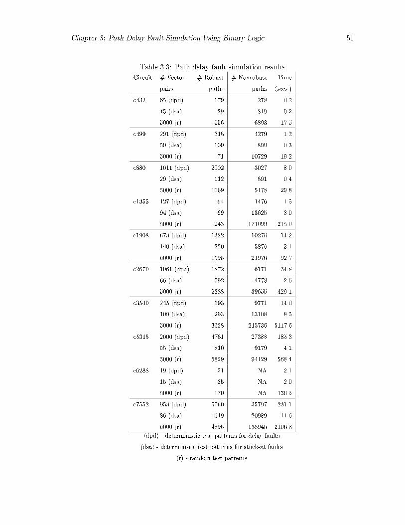
Chapter �� Path Delay Fault Simulation Using Binary Logic ��
Table ���� Path delay fault simulation results
Circuit � Vector � Robust � Nonrobust Time
pairs paths paths �secs��
c��� �dpd� �� ��� ���
� �dsa� � �� ���
��� �r� � � ���
c� � � �dpd� ��� ��� ���
�dsa� �� � ���
��� �r� �� ���� � ��
c��� ���� �dpd� ���� ���� ���
� �dsa� ��� � � ���
��� �r� �� ��� � ��
c�� ��� �dpd� � ��� ��
� �dsa� ��� ���
��� �r� ��� ���� ����
c� �� �� �dpd� ���� ����� ����
��� �dsa� ��� ��� ���
��� �r� �� �� � ���
c��� ��� �dpd� ���� ��� ����
�dsa� � ���� ��
��� �r� ���� � �� ��
c��� �� �dpd� � ��� ����
�� �dsa� � � ����� ��
��� �r� ��� ���� ����
c�� ���� �dpd� ��� ����� ����
�dsa� ��� �� ���
��� �r� �� ��� ���
c��� � �dpd� �� NA ���
� �dsa� � NA ���
��� �r� ��� NA ���
c�� � �dpd� �� �� � �����
� �dsa� � �� � ���
��� �r� �� ��� � �����
�dpd� � deterministic test patterns for delay faults�
�dsa� � deterministic test patterns for stuck�at faults�
�r� � random test patterns�
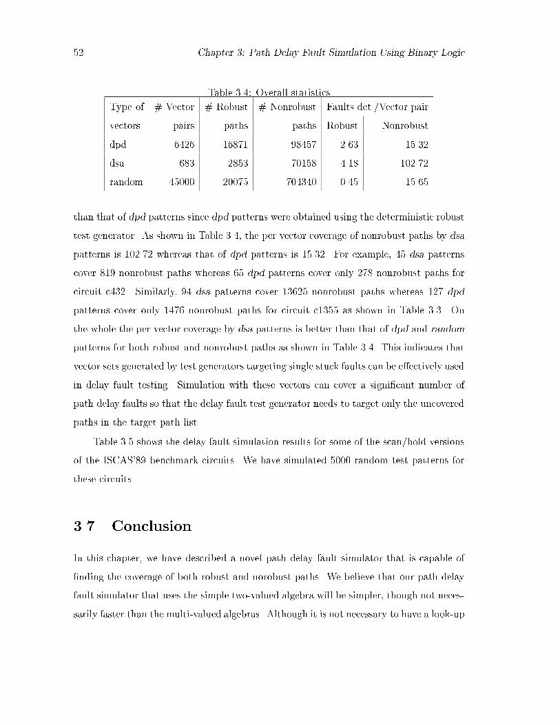
�� Chapter �� Path Delay Fault Simulation Using Binary Logic
Table ���� Overall statistics
Type of � Vector � Robust � Nonrobust Faults det��Vector pair
vectors pairs paths paths Robust Nonrobust
dpd �� �� ���� ��� ����
dsa �� ���� ���� ��� �����
random ����� ����� ������ ���� ���
than that of dpd patterns since dpd patterns were obtained using the deterministic robust
test generator� As shown in Table ���� the per vector coverage of nonrobust paths by dsa
patterns is ����� whereas that of dpd patterns is ����� For example� �� dsa patterns
cover � nonrobust paths whereas � dpd patterns cover only ��� nonrobust paths for
circuit c���� Similarly� � dsa patterns cover ��� nonrobust paths whereas �� dpd
patterns cover only �� nonrobust paths for circuit c��� as shown in Table ���� On
the whole the per vector coverage by dsa patterns is better than that of dpd and random
patterns for both robust and nonrobust paths as shown in Table ���� This indicates that
vector sets generated by test generators targeting single stuck faults can be e�ectively used
in delay fault testing� Simulation with these vectors can cover a signi�cant number of
path delay faults so that the delay fault test generator needs to target only the uncovered
paths in the target path list�
Table ��� shows the delay fault simulation results for some of the scan�hold versions
of the ISCAS�� benchmark circuits� We have simulated ���� random test patterns for
these circuits�
��� Conclusion
In this chapter� we have described a novel path delay fault simulator that is capable of
�nding the coverage of both robust and norobust paths� We believe that our path delay
fault simulator that uses the simple two�valued algebra will be simpler� though not neces�
sarily faster than the multi�valued algebras� Although it is not necessary to have a look�up

Chapter �� Path Delay Fault Simulation Using Binary Logic ��
Table ���� Path delay fault simulation results for ISCAS��� circuits
Circuit � Vector � Robust � Nonrobust Time
pairs paths paths �secs��
s�� � � � ��
s�� � �� ��� ���
s��� ���� �� �� ��
s�� ���� ��� �� ��
s�� ���� ��� �� ��
s�� ���� �� �� ���
s� ���� ��� �� ��
s��� ���� ��� ��� ��
s��� ���� �� � ���
s��� ���� ��� � ��
s��� ���� � �� ���
s�� ���� �� � ���
s��n ���� ��� � ���
s�� ���� ��� ���� ����
s�� ���� ��� �� ���
s��� ���� ��� ��� ���
s�� ���� ��� ��� ���
s�� ���� ��� �� ��
s�� ���� ���� � ���
s��� ���� ���� ���� ����
s��� ���� ���� �� ����
s��� ���� ���� ��� ����
s���� ���� ��� ���� ����
s���� ���� ���� ��� ����
s��� ���� ��� �� ����
s��� ���� ��� ���� ��

�� Chapter �� Path Delay Fault Simulation Using Binary Logic
table as required in the multiple�valued logic evaluation� we have to perform logic simula�
tion both for the �rst and second vector of each vector pair� Our experimental results on
the ISCAS��� and the scanhold versions of ISCAS�� benchmark circuits indicate that
even moderately large circuits can be handled by our simulator within reasonable CPU
time�
In the next chapter� we will discuss an e�cient automatic test pattern generation
system for path delay faults for combinational logic circuits�

Chapter �
An E�cient Automatic Test
Generation System for Path Delay
Faults in Combinational Circuits
In this chapter� we describe an e�cient automatic test pattern generation algorithm and
its implementation for path delay faults in combinational logic circuits� To facilitate
simultaneous consideration of robust and nonrobust tests� we have developed a ��value
logic system� Once a robust test is found for a path with a given transition� our algorithm
derives another test with minimal extra e�ort� The derived test in most cases is either
a robust or nonrobust test for the same path with the opposite transition� An e�cient
multiple backtrace procedure is employed for satisfying the test generation objectives� A
path selection method covers all lines in the logic circuit by the longest and the shortest
possible paths through them� We have integrated a fault simulator with the test generator�
which can cover robust and nonrobust path faults either from a targeted path list or from
all possible path faults in the circuit� Experimental results on several ISCAS� and
the scan�hold versions of ISCAS�� benchmark circuits are presented to substantiate the
e�ciency of our algorithm in comparison to other published results�

�� Chapter �� Test Generation for Path Delay Faults
��� Introduction
The path delay fault model ����� is extensively used since it represents the in�uence of
distributed delays on the operation of clocked systems� The complexity of test generation
for delay faults is rather high due to factors such as the large number of possible paths
large number of tests and the exponential search space for test generation� In this chapter
we present a novel test generation algorithm which is capable of eciently generating
robust and nonrobust tests for path delay faults in combinational circuits� We have
employed an ecient path selection procedure that targets a suitable subset of paths
from the enormously large number of possible paths in the circuit�
Most of the delay fault testing methods reported hitherto ��� �� � �� are based on the
relatively simple concept of the PODEM algorithm ����� Schulz et al� have demonstrated
an extended multiple backtrace procedure and the concept of static and dynamic learning
for path delay fault testing ��� ����� Park and Mercer �� �� have implemented a delay test
generation algorithm based on the D�algorithm for generating robust and nonrobust tests�
Their algorithms use a � �valued hazard�free logic system to prevent the invalidation of
a test due to hazard phenomena and to reduce the potential search space for delay test
generation� Several non�enumerative methods �i�e� without explicitly accounting for any
speci�c paths� for test generation and fault simulation of path delay faults have recently
appeared in the literature ��� �� ��� �����
Our method uses a multiple backtrace procedure similar to that of Schulz et al� �����
for satisfying the test generation objectives� The new ideas incorporated in our algorithm
are as follows�
�� A new ��value logic system to derive robust and nonrobust tests for path delay
faults �Section �����
�� A multiple backtrace procedure to �nd and resolve con�icts at internal nodes rather
than at PIs� This is illustrated by Example ����
�� Direct derivation of a test for the opposite transition once a test for a path for a

Chapter �� Test Generation for Path Delay Faults ��
given transition is found� This is illustrated by Examples ��� and ����
�� Tests are generated for all paths or� especially in the case of too many paths� for
one longest and one shortest path per line �Section �����
��� A ��Value Logic System
Multivalued logic has been used by practically all researchers for test generation and
fault simulation of path delay faults� In a recent paper� Bose et al� �� have used a
��valued logic system for the test generation for multiple paths� Fuchs et al� �� have
introduced ��valued logic for robust automatic test generation �ATG� and threevalued
logic for nonrobust ATG� Park and Mercer have used ��valued logic for robust test
generation ��� � The number of logic states used is a key factor that determines the
time and memory complexities of the algorithm� fewer logic symbols generally lead to less
complex implementations �� �
We have used a �value logic system �i�e�� S�� X�� FT� S�� X�� RT� XX� G�� G�� for
the generation of robust and nonrobust tests� The initial seven logic values are simply
a more explicit representation of Lin and Reddy�s �ve value system �� whereas signals
G� and G� are newly introduced in our proposed logic system� Signal values S� and S�
specify steady values � and �� respectively� for both vectors without a static hazard �glitch�
in the signal� Signals X� and X� represent the �nal logic values � and �� respectively�
whereas the initial value is X �don�t care�� Signals RT and FT specify rising and falling
transitions without a dynamic hazards� The concepts of static and dynamic hazards are
given in �� ��� ��� ��� � XX means don�t care for both vectors� G� and G� represent
static hazards �i�e�� glitches ��� and ���� respectively��
����� Derivation of ��Value Logic
Our goal is to derive an optimal logic system that will allow simultaneous consideration of
robust and nonrobust tests� In earlier literature ��� ��� �� � a multivalued logic system

�� Chapter �� Test Generation for Path Delay Faults
has been derived by manipulating three logic ��� � and X� states which are simultaneously
considered in two consecutive time frames �initial� �nal� of the clock period Similarly� we
manipulate three logic ��� � and X� states for three �initial� intermediate and �nal� sub
intervals within two clock periods in order to determine the presence of hazards between
two successive clocks Thus� we get �� � � possible transition states which are given in
Table �� These � states eventually collapse to a �value logic system
In Table ��� the transition states �� and ����� in which the logic values are fully
speci�ed� are represented by unique values� ie� �S�� G�� FT� and �S�� G�� RT�� respec
tively The composite states �transition states �� and ����� are absorbed together and
are represented by X� and X�� respectively� since the �nal value is known and the initial
or intermediate values are not fully speci�ed The last � states ��� �� are collapsed to
a single logic value XX since the �nal logic value is X �don�t care� Signal values G�
and G� represent static hazards �ie� glitches ��� and ���� and are explicitly used for
generation of nonrobust tests
G1S1RTG0FTS0
10111010101000
X1X0
XX
Figure ��� Proposed �value logic
Figure �� shows the pictorial representation of our proposed �value logic system in
which X� covers �S�� FT� G��� X� covers �S�� RT� G��� and XX covers both X� and X�
Following Agrawal et al� ���� in Table � � we have given the signal value representation

Chapter �� Test Generation for Path Delay Faults ��
Table ���� Enumeration of logic states
State Possible Fully Composite
id states speci�ed states
� � � � fS�g �
� � � � fG�g �
� � � � fFTg �
� � � � fFTg �
� X � � fS�G�g
� X � � � fS�FTg
� X X � � fS�G�FTg
� X � � fFTFTg
� X � � � fG�FTg
�� � � � fS�g �
�� � � � fG�g �
�� � � � fRTg �
�� � � � fRTg �
�� � X � � fRTRTg
� � X � � fS�G�g
�� X � � � fRTG�g
�� X X � � fS�G�RTg
� X � � � fRTS�g
�� � � X � �
�� � � X � �
�� X � X � �
�� X � X � �
�� � X X � �
�� � X X � �
� � � X � �
�� � � X � �
�� X X X � �

�� Chapter �� Test Generation for Path Delay Faults
Table ���� Signal value representation
Name of Initial Final Hazard
signal value value value conditions
S� � � no static hazard
X� X � hazard possible
FT � � no dynamic hazard
S� � � no static hazard
X� X � hazard possible
RT � � no dynamic hazard
XX X X hazard possible
G� � � static hazard ����
G� � � static hazard ����
and their corresponding logic values in both vectors�
Hazards �static or dynamic are timing anomalies in digital circuits and are caused by
inherent delays of the circuit elements� A hazard may invalidate a delay test by declaring
a faulty circuit to be good� Thus� hazards play an important role in twopattern test
generation for delay faults� For example� a twoinput AND gate having one rising and
one falling transition at the inputs will give rise to a static hazard �i�e�� glitch ��� if
the falling transition is delayed with respect to the rising transition� Examples are given
in Figure ��� showing the glitch generation�
1 0 10 1 0
1 0 0
0 0 1
1 1 0
0 1 1
G1G0
Figure ���� Examples of glitch generation
Signal values G� and G� are explicitly used for the generation of nonrobust tests�

Chapter �� Test Generation for Path Delay Faults ��
Consider the circuit of Figure ���� Suppose we have to �nd a test for the rising transition
on path AE shown in bold lines� For propagating the transition through the OR gate
we need to justify a S� on the o�path sensitizing input D� These conditions for robust
propagation are the same as given by Lin and Reddy �� � Assume that the twopattern
test vector applied is V� � ��� and V� � ���� After simulation we will get a static hazard
G� at D if the falling transition at C is delayed with respect to the rising transition at B�
The static hazard at D can appear as a dynamic hazard at E� provided that there is an
excessive delay on path AE� If the hazard at E coincides with the clock� the correct logic
value � will be latched and thus the test will be invalidated� If there is no propagation
delay on C� then the delay fault �rising transition on path AE� can be detected and thus
�V�� V�� will be a nonrobust test� For generating a robust test� we need to justify a S�
signal at D and this can be obtained by assigning S� to either input B or C�
A
B
CD
E
01
10G0
S0
Figure ���� Glitch causing a nonrobust test
��� Path Selection
There is a major bottleneck in selecting all possible paths for test generation and fault
simulation since as the circuit size increases the number of possible paths grows exponen
tially with the number of lines� In most practical cases� the large number of paths makes
it impossible to consider all paths for the purpose of delay fault testing� Hence� it may be
necessary to focus on a subset of all possible paths� There are several methods presented
in the literature like worst�case path selection and threshold�based path selection ��� � Li
et al� have presented a polynomial time algorithm to �nd a minimum cardinality path

�� Chapter �� Test Generation for Path Delay Faults
set ����� In their approach� a set of paths is selected such that each line L is included in
at least one selected path P and the modeled signal propagation delay along the path P
is maximum among all paths that contain L� In recent papers �� ��� it has been shown
that the determination of an optimal clocking period highly depends on the accuracies
of the estimated longest path delay and the shortest path delay in the circuit �e�g�� in
the case of wave pipelined combinational circuits � Furthermore� in a synchronous design�
there are instances where the minimum delay of a path may be important� For example�
if the skew between the clocks of two �ip��ops is larger than the combinational path
delay between them� then incorrect data can be latched in the destination �ip��op� In
general� the delay of paths should be greater than a lower bound that is determined by
the permissible skew of the clock signal� Hence in this work� we have introduced a method
for selecting a subset of paths that covers all lines in the logic circuit at least once and
includes the longest �L as well as the shortest �S possible path through each line ����
The procedure for longest path selection is described below for clarity�
Consider the circuit given in Figure ���� Each line is labeled with two labels� The
two labels� namely� level and depth of the line� are its maximum distances �in terms of
the number of logic levels from a PI and a PO� respectively� The labels for level of each
line are computed in a breadth��rst forward trace of the circuit during netlist reading�
For computing the depth of each line� �rst we label all primary outputs �i�e�� lines ��� ��
with the depth �� All inputs of a gate are labeled by the depth of the output of the gate
plus �� Thus� we assign lines ��� ��� and �� depth �� lines �� and � depth �� lines �� and
� depth � and so on� When a fanout stem is encountered� it is labeled by the maximum
depth of its fanout branches plus �� Thus� we assign depth � to the fanout stem ��� depth
to the fanout stem ��� and so on� We thus continue the breadth��rst backward trace of
the circuit till we reach primary inputs�
First� we begin a depth��rst trace for longest path selection from all PIs and mark
those lines as covered for which the enumerated path is the longest structural path� Next�
we enumerate the longest paths through intermediate lines which are not covered in the
already enumerated paths� During this path enumeration� we mark all PIs as covered�

Chapter �� Test Generation for Path Delay Faults ��
11 [3,1]
18 [7,2]
22 [9,0]21 [8,1]
20 [8,0]
19 [6,2]
17 [7,1]16 [6,3]
15 [4,3]
14 [5,3]
13 [5,4]
12 [4,5]
10 [3,4]9 [2,5]
8 [3,4]
7 [3,6]6 [2,7]
5 [1,6]
4 [1,8]
3 [1,8]
2 [1,6]
1 [1,4]
Figure ���� Example of path selection
In Figure ���� starting from PI �� when we reach the fanout stem ��� we choose the
fanout branch �� for depthrst enumeration since it has the maximum depth� Continuing
the trace along line ��� we reach a PO �line �� through line ��� Thus� the path P� ����
������ is found as the longest structural path through line �� We have employed the
following rule to mark whether or not a line on the path is covered by a longest path�
Rule ���� In a circuit� a line L will be marked as covered through path P if the sum
of level and depth of line L is equal to the number of logic levels in path P �
Example ���� Consider the path P� � ���������� given above which is the
longest path through line �� The number of logic levels �number of lines in path P� is ��
The sum of the level �i�e�� � and depth �i�e�� � of line � is �� whereas the sum of level
and depth for other lines is greater than �� Hence� only line � is covered by the longest
path P�� �
Next� the longest path through PI � �i�e�� P� � ������������� is enumerated
and line � is marked as covered� Then the longest path through PI � is enumerated �i�e��
P� � ��������������� � In this case� all lines of the path P� are marked as covered
since they satisfy Rule ���� Thus� the longest path through each PI is enumerated and
corresponding lines are marked as covered based on Rule ���� These paths are shown in

�� Chapter �� Test Generation for Path Delay Faults
Table ���� Longest path selection
Path Longest Lines
no� path covered
� ���������� �
��������������
� ������������������ ������������������
� ������������������ �
� �� �������� ��� �� ������
� ���������� ��� �
�� ���� ��
� ����������� ��� ����
���������������� ���
the upper half of Table ���� Next� we enumerate the longest path through the lines which
are not yet covered� To �nd the longest structural path through an internal line� we make
a backward trace toward PIs in a depth��rst manner along the lines having maximum level
and a forward trace toward POs in depth��rst manner along the lines having maximum
depth� For example� line �� is not covered by the longest paths enumerated from PIs� For
choosing the longest path through line ��� we make a backward trace and reach the PI �
through lines �� and �� Making a forward trace along the maximum depth lines from
�� in a depth��rst manner we reach the PO through lines � and �� Thus� path P�
������������ ���� is enumerated and lines �� and � are marked as covered following
Rule ����
All the chosen structural paths through each signal line are listed in Table ���� Longest
path represents the longest enumerated path� Lines covered denotes the lines for which
the enumerated path is the longest structural path� The number of path delay faults is
twice the number of enumerated structural paths since for every path we consider both
rising and falling transitions at the source of the path� In general� it is not necessary to
assume a unit weight �representing delay� for all lines� They can be assigned their rise

Chapter �� Test Generation for Path Delay Faults ��
and fall delays as weights� The above analysis will then be repeated twice� once for rise
delay and then for the fall delay�
In a similar manner� for selecting the shortest paths through each line� we trace the
circuit in both directions �i�e�� from PIs to POs and vice versa� for assigning two labels
�depthpi� depthpo� to each line L which represent the minimum length �in terms of logic
levels� from L to any PI and PO� We continue the backward and forward traces along the
minimum depth lines for selecting the shortest paths�
��� Test Generation
Given a target path and a transition at the input of the path� we must sensitize the
path to propagate the transition� In order to satisfy the primary objectives �i�e�� opath
sensitizing input values�� backtracing is carried out and PIs are assigned for obtaining a
twopattern test vector� Our test generation method uses a multiple backtrace procedure�
similar to that of Schulz et al� ������ Along with the multiple backtrace procedure� we
have used some novel and e cient backtracking techniques for detecting and resolving
con�icts on internal lines� We do not target the generation of nonrobust tests explicitly�
Once a robust test is generated for a path with a given transition� we derive another test
for the opposite transition by modifying the robust test obtained� In most cases� the
derived test becomes a robust or nonrobust test for the opposite transition on the same
path� Details of the test generation algorithm and examples are given below�
����� Procedure for Test Generation
The salient features of the test generation procedure are as follows�
� The implication operation is done with respect to the transition �rising or falling� at
the input of the path with all other inputs unspeci�ed �XX�� The main objective of
this implication procedure is to determine whether or not the transition can robustly
propagate along the target path�

�� Chapter �� Test Generation for Path Delay Faults
� The o��path inputs of the gates along the target path are then set to suitable
logic values in order to propagate the transition� The rule used to set the o��path
sensitizing inputs is as follows� If the transition at a gate input along the path
is in the direction of the controlling value of the gate� all side inputs of this gate
must have steady non�controlling logic values� if the transition is toward the non�
controlling value� all side inputs can also have transitions toward the non�controlling
value� During this propagation phase� if any one of the o��path sensitizing inputs
has already been implied during the previous step and there is a con�ict between
the implied logic value and the required sensitizing logic value� then we immediately
conclude that no robust test is possible for this path delay fault� If no con�ict is
found� the o��path inputs with the assigned sensitizing logic values become the
primary objectives� Also� we mark all fanout branches of a stem as assigned if the
stem is a part of the target path�
� It is best to �nd out any inconsistency in the primary objectives as early as possible�
Sometimes it may so happen that two or more primary objectives have con�icting
logic values and they are the fanout branches of the same stem� In that case� it is not
possible to generate a test and hence we eliminate such paths without attempting
test generation�
� We have not used controllability measures for choosing the inputs as used in FAN ��
and PODEM � �� Instead� for the sake of simplicity� we have used a heuristic
concept of fanin sorting� i�e�� we put all fanins of a gate g in an ascending order
with respect to the level number in a linked list attached to the gate g� the lowest
level input at the head and the highest level input at the tail� Hence� when a choice
exists� we �rst select the input with the lowest level number�
� In order to satisfy the primary objectives� we backtrace from primary outputs toward
primary inputs in a breadth��rst manner� This multiple backtrace procedure is the
most important aspect of our algorithm� The highest level objective generates the
previous level objectives and so on� For example� if we are required to satisfy a S�

Chapter �� Test Generation for Path Delay Faults ��
logic value at the output of an AND gate� then we choose the input having the lowest
level number �in other words easiest to control� and put that input and objective
in the level of the chosen line� The other inputs are then put on the primary stack
along with the logic value to be satis�ed� This helps in backtracking to the last
choice if we fail to generate a test in the �rst multiple backtrace process� Again� for
example� if we need to satisfy a S� logic value at the output of an OR gate� then we
put all inputs with logic value S� in their corresponding level objectives�
� During the backtrace operation� if we create a new objective on an input of a gate G
and this input happens to be a fanout branch� then we immediately create another
objective with the same logic value on the fanout stem� After doing an implication
operation we mark all fanout branches as tried� Hence� before setting an objective
on any fanout branch during backtrace� we �rst check whether or not it has already
been tried by previous objectives� If so� we intersect the already assigned logic value
on the stem with the required logic value on the fanout branches� If conict occurs
in the intersection� then the fanout branch with the required logic value is pushed
to the secondary stack�
As an example� consider the circuit shown in Figure ��� We need to satisfy the
objectives� F�S and G�X�� The value mentioned in brackets �n��� n� � n� etc��
refers to the level number� Suppose that the objective F�S is to be satis�ed �rst�
We choose the input C as it has a lower level number� assign C�S and put the other
input A�S in the primary stack which is used to store the untried alternatives�
Since C is a fanout branch� immediately it creates the previous level objective on
the stem B�S � After implication� the fanout branches C and D will be marked
as tried� When the next objective G�X� is considered� we �rst choose the input
D which has already been tried as the level number of D is lower than E� After
intersection it leads to a conict at the stem �S �X� � NULL�� Hence� input D
with logic value X� is pushed to the secondary stack and next input E is considered�
Thus we create the new objective E�X� and the backtrace procedure will continue

�� Chapter �� Test Generation for Path Delay Faults
further toward primary inputs� If all choices in the primary stack fail to generate
a test� the objectives in the secondary stack are tried� allowing the test generation
process to consider all possible choices�
A[n-1]
B[n-3]C[n-2]
F[n]
G[n]
S1
X0D[n-2]
E[n-1]
S1
X0
Figure ���� Example of con�ict at a stem
� The complexity of the test generation algorithm depends on the number of back
tracks required in generating a test� However� the eciency of test generation is
strongly in�uenced by the order in which the signals in the target list are consid
ered for justi�cation � ���� According to the existing literature� a single stack has
been used for the backtrack operation by all researchers� In this work� we use two
stacks �primary and secondary� which store alternative choices for selecting inputs�
The primary stack contains line numbers with noncon�icting logic values and the
secondary stack contains line numbers with con�icting logic values� During the
backtrack� �rst we choose the last choice from the primary stack and after comple
tion of all choices� we consider the secondary stack� Through experiments we have
found that this method has a greater advantage over the use of single stack and it
drastically reduces the number of backtracks for generating a test�
The pseudo code for the test generation algorithm is given in Figure ���� The procedure
for test generation is illustrated by the following example�

Chapter �� Test Generation for Path Delay Faults ��
Testgen�Path�Transition�
�
Imply��� �� wrt transition and other unspecified inputs ��
Propagate�Transition�� �� propagate the transition along the target path ��
If there is conflict between implied logic value and the
transition on line k� on target path then �
Transition can not propagate along the path�
No test possible� Exit���
�
Set primary objectives��� �� Find all primary objectives to be justified ��
If there is conflict between two or more primary objectives on the
fanout branches of the same stem then �
No test possible� Exit���
�
Fanin sorting��� �� puts the fanins of a gate in an ascending order
wrt the level number ��
Multiple backtrace��� �� backtrace from POs to PIs in a breadth�first manner
for satisfying test generation objectives ��
Imply��� �� Implication wrt the PI assignments ��
If all primary objectives are satisfied
then test is found�
else continue backtrace from the last choice assigned�
Substitute primary objectives��� �� X��X�� by S��S�� and vice versa ��
Modified test vector��� �� replace X��X�� by S��S�� and reverse the
transition at source of the path ��
Imply��� �� Implication wrt the new derived test vector ��
If all primary objectives are satisfied
then a test is found for the opposite transition�
�
Figure ���� Pseudo�code for the test generation algorithm
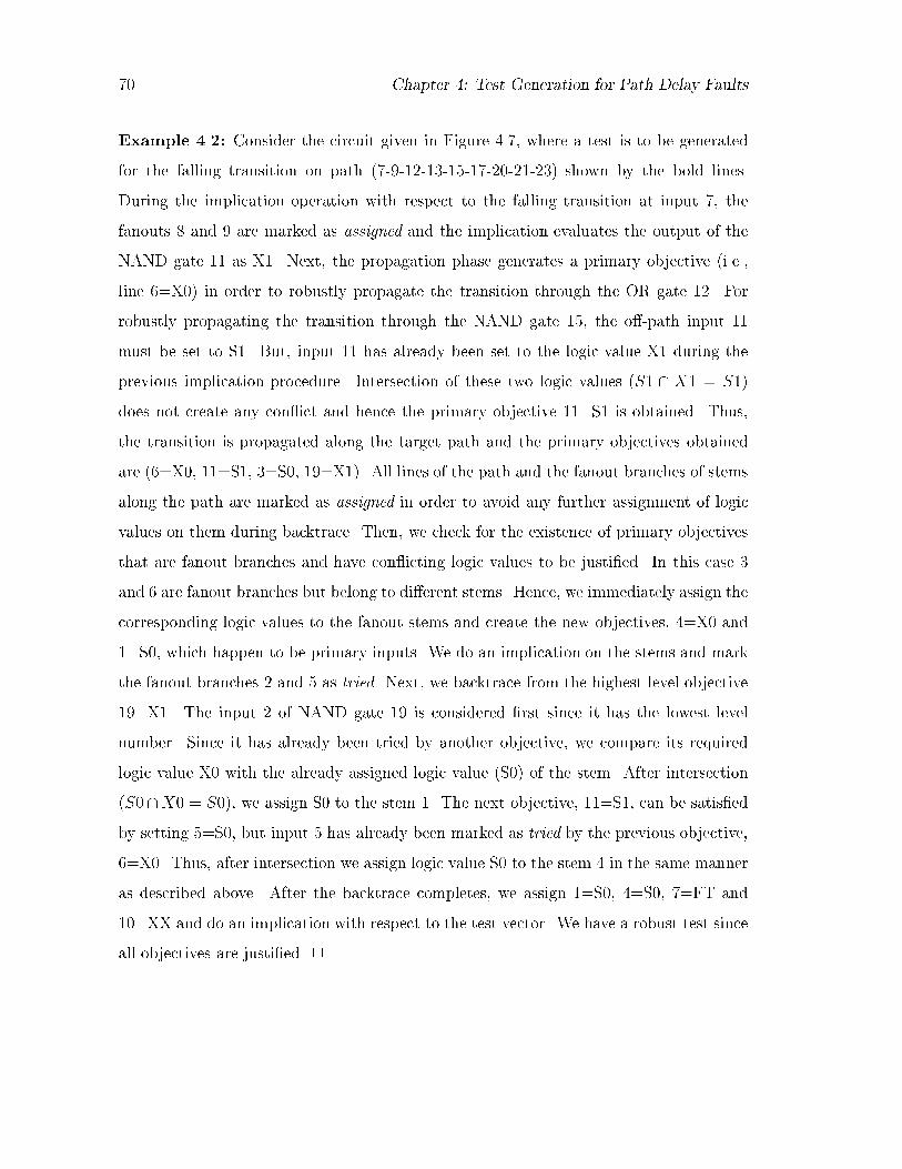
�� Chapter �� Test Generation for Path Delay Faults
Example ���� Consider the circuit given in Figure ���� where a test is to be generated
for the falling transition on path ���������������� shown by the bold lines�
During the implication operation with respect to the falling transition at input �� the
fanouts � and � are marked as assigned and the implication evaluates the output of the
NAND gate as X� Next� the propagation phase generates a primary objective �i�e��
line ��X� in order to robustly propagate the transition through the OR gate � For
robustly propagating the transition through the NAND gate �� the o��path input
must be set to S� But� input has already been set to the logic value X during the
previous implication procedure� Intersection of these two logic values �S � X � S
does not create any con�ict and hence the primary objective �S is obtained� Thus�
the transition is propagated along the target path and the primary objectives obtained
are ���X�� �S� ��S�� ��X � All lines of the path and the fanout branches of stems
along the path are marked as assigned in order to avoid any further assignment of logic
values on them during backtrace� Then� we check for the existence of primary objectives
that are fanout branches and have con�icting logic values to be justi�ed� In this case �
and � are fanout branches but belong to di�erent stems� Hence� we immediately assign the
corresponding logic values to the fanout stems and create the new objectives� ��X� and
�S�� which happen to be primary inputs� We do an implication on the stems and mark
the fanout branches and � as tried� Next� we backtrace from the highest level objective
��X� The input of NAND gate � is considered �rst since it has the lowest level
number� Since it has already been tried by another objective� we compare its required
logic value X� with the already assigned logic value �S� of the stem� After intersection
�S��X� � S� � we assign S� to the stem � The next objective� �S� can be satis�ed
by setting ��S�� but input � has already been marked as tried by the previous objective�
��X�� Thus� after intersection we assign logic value S� to the stem � in the same manner
as described above� After the backtrace completes� we assign �S�� ��S�� ��FT and
��XX and do an implication with respect to the test vector� We have a robust test since
all objectives are justi�ed� �

Chapter �� Test Generation for Path Delay Faults ��
X0
S1S0
X1
24
23
22
21
20
19
18
17
16
15
14
13
12
11
10
9
8
7
6
543
21
Figure ���� Test generation �Example ����
����� Robust�Nonrobust Test for Opposite Transition
Once we nd a robust test for a transition say rising on a target path instead of trying
to generate another test for the opposite transition i�e� falling we derive another test
by substituting the X values �X� X�� in the rst test with steady values �S� S�� and
reversing the transition at the input of the target path� The underlying principle is that
the second vector �propagation vector� of the two�pattern test is a test for the stuck�
at fault on the primary input at the source of the transition� The stuck fault at the
PI is sensitized along the target path� If the sensitizing condition remains unchanged
�i�e� all PIs have values as in V� except the PI at the source of the path� the opposite
transition will always reach the primary output along the target path� Hence we replace
the non�steady X values X��X�� by the steady values S��S�� in the generated test vector
to derive a new test vector for the opposite transition on the target path� In most cases
this modied vector pair will be a valid robust nonrobust test for the opposite transition�
In a few cases the derived test vector pair will not be either a robust or a nonrobust
test due to the presence of redundant stuck�at faults on any one of the signal lines along

�� Chapter �� Test Generation for Path Delay Faults
the target path� The following example illustrates the derivation of robust test for the
opposite transition�
Example ���� Consider the circuit shown in Figure ���� in which we �rst generate a
test for the rising transition on the target path ��� � ��� The primary objectives
to be justi�ed for this path delay fault are ��X � ��S and ��X � The highest level
objective ��X will be justi�ed by setting ��X�� Since the other two objectives are
already PI objectives� we obtain the robust test � �XX� ��X�� �RT� ��X � ��S ��
The test for the opposite transition �falling� can be derived by substituting ��S�� �FT
and ��S in the above test� Since the transition has been reversed the primary objectives
along the path will also change� The new set of the primary objectives will be ���S �
��X and ��S �� Then we do an implication with respect to the derived test � �XX�
��S�� �FT� ��S � ��S � and �nd that all primary objectives are justi�ed� Hence�
we obtain another test without explicitly executing the test generation procedure� On
average� we found that ��� of the generated robust tests actually produce either a robust
or a nonrobust test for the opposite transition for the ISCAS��� benchmark circuits� �
XX
X0
X1
S1
X117
16
15
14
1312
11
10
9
8
7
6
5
4
3
2
1
Figure ���� Derivation of test for opposite transition �Example ���
During the implication operation� we compare the primary objective logic values with
the implied logic values in order to determine the robustness�nonrobustness of a test� If
the implied logic values either are a subset �S� and G� � X�� S and G � X � of the

Chapter �� Test Generation for Path Delay Faults ��
primary objective logic values� or are the same� then the derived test will be a robust
test� If at least one of the primary objective logic values is S��S�� and the implied logic
value becomes G��G��� then the derived test will be a nonrobust test for the opposite
transition� The following example illustrates the derivation of a nonrobust test for the
opposite transition by modifying the robust test�
Example ���� In Figure �� we �rst generate a test for the rising transition on path
�� ������������ The primary objectives are ��X�� ��S� and ���X�� After backtrace
we obtain a robust test� i�e�� ���S�� �RT�� The new set of primary objectives for the
opposite transition will be ��S�� ��X� and ���S�� The derived test will be ���S��
�FT�� After implication� we �nd that the implied logic value of line �� is G� �i�e�� static
hazard ������� whereas its primary objective logic value is S�� Hence� the derived test
will be a nonrobust test for the falling transition� Thus� once a robust test is derived
for a path with a given transition� we are able to save a considerable amount of e�ort
by directly generating a robust�nonrobust test for the opposite transition on the target
path� �
X1
S1
X1
12
11
10
9
8
7
6
54
3
2
1
Figure �� Nonrobust test derived from robust test �Example ��
��� Experimental Benchmark Results
We have implemented the proposed path delay test generation algorithm in the C language
�about ���� lines of code� on an IBM RS������ �� workstation� In order to benchmark

�� Chapter �� Test Generation for Path Delay Faults
and demonstrate the e�ciency of our test generator� we have performed ATG for ro�
bust and nonrobust tests on the ISCAS��� and the scanhold versions of the ISCAS��
benchmark circuits�
Table ��� gives the results for ISCAS��� benchmarks� Path faults is the number of
logical paths considered for test generation� This is twice the number of the physical
paths selected to cover each line via the longest �L path through it� For the purpose
of comparison� we have also given the test generation results when the path selection
procedure is modi�ed to choose the shortest �S path through each line� As expected� in
general� the coverage is higher for shorter paths� We have integrated a fault simulator ���
in the system� Once a robust or nonrobust test is generated� immediately we do fault
simulation with respect to the test vector� Both robust and nonrobust detection of path
delay faults are reported� Robustly detected paths are then marked in the targeted path
list and hence not considered for further test generation� The third and forth columns of
Table ��� give the number of robust and nonrobust tests generated by the test generator
within the backtrack limit of ���� The �fth and sixth columns give the number of path
faults which are robustly and nonrobustly tested from the targeted fault list while columns
seven and eight are for the non�targeted faults� The CPU time �in seconds is given for the
complete ATPG process� For circuit c����� the number of nonrobustly detected paths was
extremely large even for a small number of tests and requires a large amount of CPU time
and memory for a successful completion� Hence� we have not considered the nonrobust
detection of paths during simulation�
Our results in Table ��� may be compared to two earlier works ����� ���� on test
generation for ISCAS��� benchmarks� Their results are included in Table ���� We have
given our results only for longest paths� However� since the number of modeled path faults
and the machines used are di�erent� a direct comparison can not be made� It may be
noticed that the fraction of modeled path faults that are robustly tested by our method is
signi�cantly higher than that reported in both previous papers ����� ����� For example�
in our method� the fraction of targeted path faults that are robustly tested ranges from
� to ����� with the average being ������ The results reported by Schulz et al� ����� are

Chapter �� Test Generation for Path Delay Faults ��
Table ���� Delay test results for ISCAS��� benchmarks
Tests Paths detected Paths detected
Circuit Path generated �Targeted� �Non�targeted�
faults Rob� Nrob� Rob� Nrob� Rob� Nrob� CPU s�
c��� ��L� � � � � � ��� ����
��S� � � �� � � �� ����
c���� �����L� � � � � � � �����
�����S� � � � � � ����
c���� � ��L� �� � �� �� �� ������
� ��S� ��� � � � �� � � �����
c �� ��L� �� � ��� �� �� ���� ����
��S� � ���� � �� ��� ���� �
c��� ���L� � � �� ��� � ������
���S� �� � �� �� ���� ���� �����
c���� ��L� � �� � ��� ������
��S� ��� ��� ��� ��� �� �� ����
c �� �� �L� � � � NA � NA �������
�� �S� ��� � �� NA �� NA �����
c��� ����L� � ��� ��� ��� ���� �����
����S� ��� �� �� ��� �� � ��� ����
� IBM RS��������
Table ���� Comparison with other results
Our ATPG NEST ��� � Schulz et al� �� �
Circuit Target Tested CPU s� Target Tested CPU sy Target Tested CPU sz
paths paths paths
c��� ��L� � � � �� � �� �� ��� �� ��
c���� �����L� � �� ��� �� �� ������ � ��
c���� � ��L� �� ��� ����� � ��� ����
c �� ��L� ��� � ������ ��� �� ���� � �� ���
c��� ���L� �� ��� ������ � ��� �� ��� ����
c���� ��L� � ��� � �� �� ���� ��� ��� � ��
c �� �� �L� � ���� ����� ���� � ���� ����� � ���
c��� ����L� ��� ��� �� �� �� �� �� � ���
� IBM RS�������� y SUN SPARC z Micro�VAX

�� Chapter �� Test Generation for Path Delay Faults
also for the longest paths and the fraction of targeted path faults that are robustly tested
ranges from � to ������ whereas the average is only ��� In Pomeranz et al� ���� the
percentage coverage will be extremely low since it implicitly considers all possible paths�
Our results show that the test generation for path delay faults can be e ectively done for
both longest as well as shortest paths by the proposed algorithms�
Table ��� presents the results of our algorithm for scan�hold versions of ISCAS���
benchmark circuits� Path faults is the number of both rising and falling transitions on
all possible physical paths� Under Our ATPG� Rob��nrob� tests is the number of robust
and nonrobust tests generated within the backtrack limit of ��� Rob� det� is the number
of path faults which are robustly tested� Nrob� det� is the number of path faults that
are nonrobustly tested by the fault simulator� The CPU time �in seconds�� given for the
IBM RS��������� workstation� includes the time for test generation and fault simulation�
For the last eight benchmarks shown in Table ���� we have considered only a subset of all
possible path faults since the total number of paths in these circuits was very large� These
paths were obtained by the path selection algorithm given in Section �� and include one
shortest path per line�
For comparison� we include the results of three other papers ��� � ��� in Table
��� which report the coverages of robustly tested paths and CPU times� All possible
path faults are modeled in Bhattacharya et al� ��� and Bose et al� ��� Fuchs et al� ����
have presented a highly e�cient ATPG algorithm called RESIST which considers all path
delay faults in the ISCAS��� benchmark circuits� Their method presents the best available
results on path delay faults and the CPU time is given for SUN SPARC IPX� For a direct
comparison� CPU times must be normalized for the corresponding machine speeds� Such
normalization has not been done in Table ���� However� our ATPG algorithm appears to
be more e�cient than the technique of Bose et al� �� and the fault coverage is comparable�
The CPU times reported in Bhattacharya et al� ��� and Fuchs et al� ���� are better than
our results�
In RESIST ����� an e�cient sensitization technique has been proposed that sensitizes
common subpaths only once� The method resulted in a substantial decrease in the number

Chapter �� Test Generation for Path Delay Faults ��
Table ���� Test results for scan�hold versions of ISCAS�� benchmarks
Our ATPG ��� ���� ����
Circuit Path Rob��nrob� Rob� Nrob� CPU Paths CPU Paths CPU Paths CPU
faults tests det� det� sy det� s�� det� sz det� sx
s �� �� �� � ���� �� ��� �� ��� �� ����
s� �� ��� � ���� �� �� �� � �� ��
s� �� ��� � ��� ��� �� ��� ��� ��� ��
s��� �� ����� ��� �� �� ��� ��� �� �� ��� ��
s��� �� ����� ��� �� �� ��� ��� �� ��� ��� ��
s� �� ������ ��� �� �� �� ��� ��� ���� �� ���
s� � ��� ���� ��� ��� ��� ��� � � ��� ���
s��� �� �� �� ��� �� ��� ��� ��� � � ��� ���
s�� � ���� �� � ��� � ��� � ��� � ��
s��� ��� ����� �� ��� ���� � � �� ��� ��� � � ���
s��� � ���� � �� �� � ��� �� ���� � ���
s�� � ���� ��� �� ���� ��� ��� � � ��� ���
s��n �� ��� �� �� ��� ��� ��� � � ��� ���
s��� �� ������ ���� �� �� ��� �� � � �� ���
s � � � ����� ��� ��� � � ��� ��� � �� � � ��
s � ��� ����� ��� �� ��� � � ��� �� ��� � � ���
s � �� ����� ��� � ����� �� �� � � �� ��
s��� �� � ��� ��� � ����� �� ��� � ��� �� ��
s���� ���� �� � ��� ��� � ��� ���� �� �� �� � ����
s�� �� ������ ���� � � �� ���� � � �� ���
s�� ��� ���� � �� �� ��� � � ��� � �� �� � � ���
s���� ��� ���� � � � �� � � ��� � � �� � ���
s�� �� ���� � ���� ��� ��� � ��� � �� �� ���� � ��� ���
s�� � �� ����� � � � ��� �� � �� � � �� ���
s��� ��� ��� �� �� � �� ��� ����� � � �� ���
s��� � �� �������� ��� ��� ��� �� � � ��� � � ��� ���
s��� �� � ������ ���� �� �� � ��� ��� � � ��� ����
s�� �� ����� ����� ���� �� �� � � � � ���� ���
s���� ���� ������� ����� �� � �� � � �� � � � �� � �����
s� �� �� � ������� ���� ���� ����� � � � � �� � � ��
s� � � ������ � ������ �� ���� �� ��� ��� � � ��� ����
� Partial set of path faults y IBM RS����� �� DECstation ������� z SUN SPARC
x SUN SPARC IPX

�� Chapter �� Test Generation for Path Delay Faults
of subpath sensitization steps� The sensitization procedure has been shown to give a
speed�up factor that grows linearly with the circuit depth� Compared to conventional
approaches� RESIST is capable of detecting a signi�cantly larger number of path delay
faults in less time� The technique of sensitizing common subpaths only once may be
readily applied in our algorithm as well to obtain substantial speed up�
In the BDD approach ��� a combination of the conventional fully transitional path
FTP� approach to path activation and the single input transition SIT� method provides
a high coverage of robustly detectable path delay faults� Every major step in the test
generation process consists of manipulation of Boolean functions and does not require
enumeration of input patterns or covers and hence the algebraic approach can be faster
than existing methods� However� it must be remembered that the time and memory
complexities of the BDD approach �� can be impractical for some circuits� This method
has been applied to synchronous circuits also� However� results only for smaller ISCAS���
benchmarks are reported � ��
The novel ideas developed by us such as the ��value logic system� the e�cient multiple
backtrace technique and direct derivation of tests for the opposite transition from a given
test can be used to further enhance the performance of any delay test generation package�
��� Conclusion
In this chapter� we have presented a novel path delay test generation algorithm which
incorporates an e�cient multiple backtrace procedure for signal value justi�cation� The
��value logic system provides an e�cient way of deriving both robust and nonrobust tests�
Once we �nd a robust test for a path delay fault� we modify it to derive another test for
the opposite transition� In most cases� the derived test is either a robust or a nonrobust
test for the same path with the opposite transition� Thus� we are able to considerably
reduce the test generation time� A subset of paths is selected for test generation covering
all lines in the logic circuit at least once� This subset includes the longest and shortest
paths through each line� We use a fault simulator for robust and nonrobust detection of

Chapter �� Test Generation for Path Delay Faults ��
path faults�
In the next chapter� we will discuss a new coverage metric and a two�pass test gen�
eration method for path delay faults through the longest robustly testable path to cover
each signal line of the combinational logic circuits�

Chapter �
Line Delay Fault Model and Its
Coverage
In this chapter� we propose a coverage metric and a two�pass test generation method for
path delay faults in combinational logic circuits� The coverage is measured for each line
with a rising and a falling transition� However� the test criterion is di�erent from that of
the slow�to�rise and slow�to�fall transition faults� The new test� called the line delay test�
is a robust path delay test for the longest sensitizable path producing a given transition
on the target line� The maximum number of tests �and faults� is limited to twice the
number of lines� However� the line delay test criterion resembles the path delay test and
not the gate or transition delay test� Using a two�pass test generation procedure� we begin
with a minimal set of longest paths covering all lines and generate tests for them� Fault
simulation is used to determine the coverage metric� For uncovered lines� in the second
pass� several paths of decreasing length are targeted� We present a theorem stating that
a redundant stuck�at fault makes all path delay faults involving the faulty line untestable
for either a rising or falling transition depending on the type of the stuck�at fault� The use
of this theorem considerably reduces the e�ort of delay test generation� We give results
on several benchmark circuits�
�

Chapter �� Line Delay Fault Model ��
��� Introduction
In this chapter� we combine relevant features of transition ����� and path delay fault �����
models and de�ne line delay tests A rising line delay test will test the longest sensitizable
path passing through the target line producing a rising transition on it Similarly� a
falling line delay test is de�ned The de�nition of longest can be appropriately chosen
For example� in the simplest case� it can be the path with the largest number of gates
Alternatively� gates can be weighted by their nominal delays However� once the path is
selected� the test generation is independent of the gate delays The criterion of delay test
through the longest path has been used for diagnosis ���
The coverage is measured for all lines with two possible transitions Thus� the max�
imum number of faults or tests� is twice the number of lines For example� in c�����
we will consider only ���� line delay faults� whereas the total number of possible path
faults is � ����� ����� Yet� the test criterion is similar to the path delay fault� and not
like the gate or transition delay fault In general� a test will cover several lines This cov�
erage methodology can also be applied to the reported methods that extract sensitizable
paths ���� ���
Conventional path delay test generators attempt to derive robust tests for a subset
of paths in the circuit� based on some path selection criterion such as the worst�case path
selection or threshold�based path selection ����� However� a large number of these paths
may not be robustly testable and hence the test coverage of the targeted paths can be
very low eg� only about ����� paths in c���� are reported as robustly testable� The
new coverage metric seeks to remove this de�ciency by attempting to derive a pair of line
delay tests for each line in the circuit A ���� coverage of line delay faults gives the
user the con�dence that the longest sensitizable paths through each line in the circuit are
covered by the vectors The two�pass test generation method proposed here can achieve
this goal� given su�cient computational resources
The basic idea of an iterative approach for generating a robust test was �rst proposed
by Park and Mercer ����� They have followed an approximate method where the search

�� Chapter �� Line Delay Fault Model
space of the test generation process is biased to �nd a test along a path whose propagation
delay is greater than or equal to a prede�ned threshold value� Our method� on the other
hand� uses an exact method for generating a robust test for the longest testable path
through each line� To facilitate the simultaneous consideration of robust and nonrobust
tests� we have used the ��value logic system described in Chapter � ���
A major improvement in the performance of a delay fault test generation algorithm
can be obtained by avoiding test generation for those path delay faults which are guar�
anteed to be untestable� We have employed the information on redundant stuck�at faults
in the circuit� provided by a stuck�at fault test generator� to avoid test generation for
a large number of untestable path delay faults� We have achieved signi�cant savings in
computational time by this novel approach�
��� Line Delay Tests and Coverage Metric
A line delay test is de�ned as a robust test for the longest sensitizable path passing
through the target line producing a given transition on the line� One may consider line
delay tests with respect to the rising as well as falling transitions on the target line� The
motivation of de�ning the line delay test is to determine the smallest incremental delay
associated with a rising or falling transition at any line that can be robustly detected by
a test vector� Let �L be the incremental delay of a rising or falling transition through
line L� Then for detection of this delay fault�
�L TP � TC �� �L � TC � TP ���
where TC � system clock period and TP � nominal delay of the path P through which
L is tested� From the above relation ���� we determine that the smallest incremental
delay fault on L can be detected via the path through L having the longest nominal delay
�TP �max� i�e��
��L�min � TC � �TP �max ���

Chapter �� Line Delay Fault Model ��
By sensitizing the longest path through L� we are able to detect the delay fault of the
smallest size� However� simultaneous delay variations are possible for other gates on P
due to correlation with L� Suppose that the delays of other gates increase� Then the
line delay test for L will detect a delay fault of even smaller size� If the delays of other
gates reduce while that of L increases� the sensitivity of the tests reduces� Considering
correlation of delays� this later case is less probable� The basic assumption associated
with the line delay fault model is that the delays of all gates are not reduced below their
nominal values�
The major advantage of this fault model is that the number of faults is limited to twice
the number of lines in the circuit� Since the fault is tested along the longest propagation
path� the system timing failures caused by the smallest localized delay defects or the
accumulation of distributed delay defects can be detected� In the transition fault model�
a delay test is obtained along any arbitrary path because the size of delay fault is assumed
to be large enough to be tested via any path through the fault site� In the gate delay fault
model one has to specify the exact sizes of the delay defects and accurate information may
not be always available� Both transition and gate delay faults do not model the distributed
delay defects along a target path� Our model� on the other hand� retains many advantages
of the transition and gate delay fault models� while alleviating the major drawback of the
path delay model �viz�� too many paths to be tested and the low fault coverage��
��� Two�Pass Test Generation
Finding the longest sensitizable and robustly testable path through a given delay fault
site is an NP�hard problem ���� We �rst attempt to �nd a robust test for the longest
structural path through a line� If the path is not sensitizable� then we try to �nd a robust
test for successively shorter structural paths� until a test for the longest sensitizable path
is found� Given enough resources �CPU time and memory� this method guarantees to
�nd a test for the longest sensitizable path through the line if such a test exists�
The �rst pass of our two�pass test generation strategy is essentially the same as

�� Chapter �� Line Delay Fault Model
reported in Chapter � ����� Initially a simple path selection method is employed to obtain
a list of paths that cover all signal lines by their respective longest structural paths�
This method of path selection has been explained in Chapter �� The multiple backtrace
procedure employing a ��value logic system ���� is used to derive robust tests for these
targeted path faults� Once a robust test is generated fault simulation is carried out to
obtain information on the robust detection of other path faults� Whenever the simulator
nds that a path in the circuit is robustly tested by the generated test vector pair each
line on this path is examined to see if the vector pair satises the criterion of being a line
delay test for any other line on that path� If the robustly tested path happens to be the
longest structural path in the circuit through any line then that line can be marked as
covered since a line delay test has been obtained for the line with respect to a rising�falling
transition� The fault coverage includes lines and transitions for which line delay tests were
obtained�
The line delay fault coverage at the end of the rst pass is generally low since many
structural paths are not robustly testable� For each line that is not covered by the line
delay tests in the rst pass we attempt to derive a robust test for the second longest
structural path� If a robust test exists for this path we mark the corresponding line as
covered� If a test is not possible for the second longest structural path then we go for the
third fourth etc� successively shorter paths until we get a robust test� Once a line delay
test is obtained for a line L through the Nth longest path PL we mark line L as covered�
The simulator then determines the other lines in the circuit for which the generated test
satises the criterion for a line delay test� The successive line segments following L along
the tested path PL will be marked as covered if the level numbers of these successive
line segments di�er only by � This strategy usually obtains signicantly improved line
delay fault coverage after the second pass� The procedure for two�pass test generation is
illustrated by the following example�
Example ���� Consider the circuit given in Figure �� � Lines are numbered through
��� The label of line l is l�m�n� where m and n are level and depth respectively� These
are the maximum distances �in terms of the number of logic levels� from primary inputs

Chapter �� Line Delay Fault Model ��
and primary outputs� In the �rst phase of the two pass test generation procedure� we
select a list of paths that cover all signal lines through the longest propagation delay path
using the algorithm discussed in Section ���� We assume that a unit delay is associated
with each signal line� There are a total of �� signal lines and hence we have �� line delay
faults to be tested� The list of longest paths selected in the �rst pass is given below
� ���������
�� ��������������
�� ���� �������������
�� ���� �������������
�� ��������������
�� ��������������
� �������
�� ���� �����������
�� ���� ������� ���
S0
XX
X1S1
X0
S1
11 [3,1]
18 [7,2]
22 [9,0]21 [8,1]
20 [8,0]
19 [6,2]
17 [7,1]16 [6,3]
15 [4,3]
14 [5,3]
13 [5,4]
12 [4,5]
10 [3,4]9 [2,5]
8 [3,4]
7 [3,6]6 [2,7]
5 [1,6]
4 [1,8]
3 [1,8]
2 [1,6]
1 [1,4]
Figure �� Test generation for longest path through line �

�� Chapter �� Line Delay Fault Model
We try to derive robust tests for the above selected paths and it is found that only
� robust tests �vector�pairs� are generated for the �� targeted path faults� After fault
simulation with these � robust tests we nd that �� line delay faults are covered� These
are lines � �� �� �� � and �� which are covered for both rising and falling transitions
on them� Hence the line delay coverage at the end of the rst pass is only ����� or ������
Consider line � which has not been covered in the rst pass since the longest path
through line � �i�e� ������������������������ is not robustly testable with respect to both
rising and falling transitions� We then enumerate the list of successively shorter paths
through line � as listed below�
�� ����������������������� �longest path�
�� ��������������������
�� ������������� ������
�� ���������� ������
We now derive a robust test for the falling transition on the path ������������������
�� �which is one of the second longest paths through line �� as shown in Figure ���� We
get a robust test as ��S� ��X� ��S� ��FT and ��XX for this path using our test
generator and hence this test will be a line delay test for the falling transition on line �
which is now marked as covered� Now the simulator is invoked and it is found that all
other line segments of the tested path �������������������� will also be marked as covered
since successive line segments di�er in their levels only by �� Once a test is obtained for a
path with a given transition another test for the same path with the opposite transition
is immediately derived with a small extra e�ort� Thus we get another test for the rising
transition on the same path by suitable substitution on the already derived test vector
�i�e� ��S� ��S� ��S� ��RT and ��XX� which is a rising line delay test for line
�� The details of derivation of the test for the opposite transition have been discussed
in Chapter �� At the end of the second pass our algorithm succeeds in obtaining �����
coverage of all �� line delay faults in the circuit by a total of �� derived tests �vector�
pairs�� The six line delay faults on lines � �� and �� are found to be untestable through

Chapter �� Line Delay Fault Model ��
any path for both rising and falling transitions� giving a fault e�ciency of ����� �
It may so happen that there is no test for the second longest path through a given
line� In that case� we try to generate a test for the next longest or successively shorter
paths until we obtain a test for the longest robustly testable path� Our main objective is
to cover all� or most� signal lines for delay defects through the longest sensitizable paths�
In most other methods� if it is not possible to derive a test for a target path� then the
next targeted path is tried� However� this does not guarantee that the longest robustly
testable path through each line in the circuit will be tested�
XX
S1
X0
S1
11
9
7
64
3 21
19
20
18
17
16
15
14
13
12
10
8
5
2
1
22
Figure �� Test generation for second longest path through line �
��� N�Longest Path Selection
Yen et al� have presented an algorithm to nd the K longest paths of a directed acyclic
graph �DAG� ������ Ju and Saleh presented an incremental algorithm for enumeration of
paths� which is log�linear in complexity ����� Kundu has given a linear time complexity
algorithm that nds the next k longest or shortest paths of a directed acyclic graph
on demand� without recomputing all previous paths ����� However� for simplicity of
implementation� we use a path selection algorithm that is enumerative� We enumerate

�� Chapter �� Line Delay Fault Model
all possible paths through the target line L� order the paths according to decreasing
length� and retain only the N longest paths at any given time� This brute�force approach
is used only to demonstrate the e�ectiveness of the new fault model� In a production
implementation� any of the cited approaches can be used for e�cient path selection�
We �rst trace backward in a breadth��rst manner from line L toward PIs and mark
all signal lines from which there is a path to L� We then trace forward from line L in a
breadth��rst manner toward POs and mark all signal lines that can be reached from L�
For each PI that has been marked in the backward trace from L� we enumerate all paths
starting at the PI and passing through L� by traversing depth��rst along only the marked
lines� As each path is enumerated� we store it in a linked list in decreasing order of path
lengths� If the total number of possible paths through line L is greater than N � then we
insert the �N �th path into the ordered list at the appropriate position and remove the
last path from the list to retain only the N longest paths� Our approach however is not
suitable for handling circuits which have extremely large number of paths �e�g�� c� ����
However one can implement Kundu�s algorithm ���� to overcome this problem�
��� Elimination of Untestable Path Faults
In this section� we present the integration of a stuck�at fault test generator �COM�
PACTEST� ��� in our ATPG system for the elimination of untestable path delay faults�
The main objective of this approach is to save the unnecessary computational time spent
in generating tests for some of the untestable path delay faults� COMPACTEST� though
based on PODEM� is not primarily intended as a redundancy identi�er� It fails to identify
some redundant faults� We have employed COMPACTEST since this was the only ATPG
tool available to us� Better results can be obtained with more e�cient programs for redun�
dancy identi�cation � �� � � �� ��� The following theorem relates to the identi�cation
of untestable path delay faults�
Theorem ���� Consider an untestable �redundant� stuck�at�� �stuck�at�� fault on
line k in a logic circuit� Then all path delay faults for paths through line k �and hence

Chapter �� Line Delay Fault Model ��
the line delay fault on line k� for which a rising �falling� transition reaches line k will be
untestable�
Proof� We consider an untestable stuck�at�� fault on line k� The proof for the
opposite case is analogous� Since the stuck�at�� fault on line k is untestable� the logic
function realized by the circuit is unaltered when we replace the logic value on line k with
a constant �� Replacing the logic value to a constant � can also be viewed as a rising
transition� due to arrive at line k� which is innitely delayed �line k never attains the
value and hence is �stuck� at logic ��� Thus if the stuck�at�� on line k does not alter
the good circuit behavior �does not cause an incorrect logic value at the output�� then an
innitely delayed rising transition on line k also cannot cause an incorrect logic value at
the circuit output� Hence all path delay faults through line k for which a rising transition
arrives on line k will be untestable in the circuit� �
In a preprocessing phase� we run COMPACTEST for determining the redundant
stuck�at faults and keep this information in a separate le� After reading the circuit
netlist� we read the redundant faults from the le and mark the corresponding lines�
Before invoking test generation for a path delay fault� we rst examine whether or not
any line along this path is redundant for stuck�at faults� Thus� we save a large amount of
computation time by avoiding test generation for untestable path faults� This procedure
is explained in the following example�
Example ���� Consider the circuit given in Figure ��� This is a highly redundant
�contrived� circuit for stuck�at faults� The faults ��� �notation for line � stuck�at����
����������������� and �� are proved to be redundant by COMPACTEST�
Considering� for example� the fault � �line stuck�at��� we conclude that no test
can be obtained for the falling transition on any path passing through line � However�
a test may be possible for the rising transition on any path passing through this line�
Hence� we run the test generator to obtain a test for the rising transition on path ��
����� and nd �X�� ��RT� �S� and ��S� to be a robust test� If both stuck�
at�� and stuck�at� faults are redundant on any line L� then we conclude that all paths
passing through L are untestable for both rising and falling transitions� In this way� we

�� Chapter �� Line Delay Fault Model
1 2
3
4
5
6 7
8
9
10
11
12
13
14
15
X0
S0
S0
Figure ���� Elimination of untestable path delay faults
avoid some of the untestable path delay faults and make the ATPG process faster� For
example� there are ��� redundant stuckat faults in c��� circuit� By employing this
information for eliminating untestable path delay faults� we completed the twopass test
generation in ��� � seconds �CPU time on IBM RS�������� workstation� as given in
Table ���� whereas it took �� � seconds when the redundancy information was not used�
COMPACTEST took only �� seconds for identifying all redundancies in circuit c���� �
��� Experimental Results
We have implemented the proposed twopass test generation algorithm in the C language
�about ��� lines of code� on an IBM RS�������� workstation� In order to benchmark
and demonstrate the e�ciency of our algorithm� we performed an experimental study of
the ISCAS��� and scan�hold versions of ISCAS��� benchmark circuits�
Table ��� gives the results for the ISCAS benchmarks� Total LDF denotes the total
number of line delay faults which is twice the number of lines in the circuit� Red� Flts�
gives the number of redundant stuckat faults obtained by COMPACTEST which are

Chapter �� Line Delay Fault Model ��
Table ���� Two�pass test generation results for ISCAS benchmark circuitsTotal Red� Pass I Pass II Final Total
Circuit LDF Flts� Target Vec� Paths LDF CPU Vec� Paths LDF LDF CPU
Paths Tested Cov� s � Tested Cov� Cov� s �
c��� ���� � ��� �� �� �� � �� ��� ��� �� ��
c���� ��� � ���� � � � �� � � ��� ���� ����
c��� ���� ��� � ��� �� �� ��� ��� ���� ���� ���
c��� ���� ��� ��� �� ���� ���� ��� �� ��� ���� ���� ���
c���� ���� ��� ��� �� ��� ��� ��� �� ��� ��� ��� ���
c���� ����� � ���� ��� ���� ���� ���� ���� ��� ���� ��� ���
c���y ���� �� ��� � � �� ���� y y y ��� y
c��� ����� ��� ���� ��� �� ��� ��� �� ��� ���� ��� ����
s� �� � � �� �� � ��� � � ��� ���
s�� ��� � ��� �� ��� ��� �� � � � �� ��
s� �� � � ��� � ��� ��� � � �� ��� ���
s��� ��� � �� ��� �� ��� ��� � �� ��� �� ���
s�� �� �� ��� �� ��� ��� � �� ��� ���
s�� ��� � ��� �� ��� �� ��� �� �� �� ���
s��� �� � �� �� ��� ��� ��� � � � �� ���
s��� ��� � ��� ��� ��� �� ��� �� �� ��� ���
s�� ��� � ��� �� ��� ��� ��� � � � �� ���
s��� ��� �� �� �� �� ��� ��� �� �� ��� ��� ���
s��� ��� � �� �� �� ��� ��� �� �� �� �� ���
s�� ��� � ��� �� ��� � �� � � �� ��� ���
s��n ��� � ��� �� ��� �� �� � � �� �� ���
s��� �� � ��� � ��� �� �� ��� �� ��� � ��
s��� ��� �� ��� ��� �� ��� ��� ��� ��� �� ���
s�� ���� � �� ��� �� ���� ��� � � � ��� ���
s�� ���� �� ��� ��� �� ��� ��� � � � ��� ���
s��� ���� � �� ��� �� ���� � � � � �� �
s�� ��� � ��� �� ��� ���� ��� � �� � �� ���
s��� � � ��� � �� ��� ��� � �� ���� �� ����
s��� ��� � ���� ��� ���� ���� ���� ��� � ��� ����
s��� ��� �� ��� ��� �� �� ���� ��� �� �� ��� ����
s���� �� � ���� ��� �� ��� ��� � �� � ��� ����
s��� �� � ��� �� �� ��� ���� �� �� �� ��� ����
s���� ����� �� �� ��� ��� ���� �� ��� �� ��� ��� ��
s�� ����� ��� ���� ��� ��� ���� ��� ���� ����� � ���
s���� ���� ���� ��� ���� ���� ��� �� ��� ��� ��� ����
s����� ��� ��� � ��� ���� ���� ��� ��� ����� ���� ���
� IBM RS��������� COMPACTEST did not identify any redundant faults
y Pass II incomplete

�� Chapter �� Line Delay Fault Model
used to avoid test generation for untestable path delay faults� The fourth column� Target
Paths� gives the number of logical paths considered for test generation in the �rst pass�
This is twice the number of the physical paths selected to cover each line via the longest
path� The �fth column� Vec�� gives the number of robust tests �vector�pairs� generated
in the �rst pass within a backtrack limit of � We have a fault simulator in the test
generation system� Robustly detected paths are immediately marked in the targeted path
list and hence not considered for further test generation� The sixth column� Paths Tested�
gives the total number of path faults detected robustly from the Target Paths as well
as from all other path faults� as reported by the fault simulator� LDF Cov� �seventh
column� gives the number of line delay faults �LDF� detected in the �rst pass� The CPU
time �in seconds� is given for the �rst pass in the eighth column� The ninth column� Vec��
gives the number of additional robust test vectors generated in the second�pass of test
generation� For the second pass� we have enumerated up to longest paths through
each line although more paths may exist for some lines� Paths Tested gives the number of
additional paths tested robustly at the end of the second pass� The eleventh column LDF
Cov� gives the number of new line delay faults detected in the second pass� The twelfth
column Final LDF Cov� gives the total percentage line delay fault coverage obtained at
the end of two�pass test generation� The CPU time �in seconds� in the last column is for
the complete ATPG process including both passes�
For example� we have initially targeted ��� longest paths �Target Paths� for circuit
c� �� There is a total of � line delay faults which is twice the number of lines in
the circuit� In the �rst pass of the test generation process� � � robust test vectors are
generated� After simulation with these vectors� we found that �� path delay faults in the
circuit are detected robustly and ���� line delay faults �LDF� are detected in the �rst pass
of the ATPG process corresponding to a line delay fault �LDF� coverage of ���� After
the two�pass test generation process� we obtain another � extra robust tests which in
turn detect an additional �� path faults robustly and � �� new line delay faults� giving
a total coverage of ��� �� The total time taken for the complete test generation process
is ���� seconds� The line delay fault coverage is less than � in many circuits primarily

Chapter �� Line Delay Fault Model ��
due to the backtrack limit employed by us in the test generation process to keep the time
complexity manageable� In other cases� it is due to the path limit of ��� used in pass II�
The details are presented in Table ���� Furthermore� many circuits have a large number
of untestable line delay faults�
COMPACTEST did not identify redundant stuck faults in some circuits� although
these circuits are known to have several redundant faults ���� Such cases are shown with
�� in Tables ��� and ���� The ATPG timings could improve considerably if all redundant
stuck faults are identi ed for these circuits� Since our N longest path algorithm cannot
handle circuit c����� pass II remained incomplete for that circuit�
We have given the statistics for line delay coverage e�ciency in Table ��� for the
ISCAS benchmark circuits� Total LDF is the total number of line delay faults and is
twice the number of lines in the circuit� Tested LDF gives the total number of line delay
faults tested after the two�pass test generation process� The fourth column� Untestable
due to Red� stuck fault� gives the number of redundant stuck�at faults� All paths untestable
gives the number of line delay faults� which are proved to be untestable after trying to
generate a test for all possible paths through a given line� Under the column� Aborted due
to Backtrack limit� we give the number of line delay faults dropped due to a backtrack
limit of ��� and Path limit gives the number of line delay faults dropped due to the path
limit of ���� For the faults aborted due to the path limit� we have tried only the rst ���
longest paths and all of these were found untestable� although more than ��� paths can
be enumerated through these lines� Fault e�ciency gives the line delay coverage e�ciency
in percentage and is computed by dividing the sum of tested faults and proved untestable
faults with the total LDF�
��� Limitations of the Fault Model
The strengths of the line delay fault model were discussed in Section ��� and now we will
discuss some of its limitations� In order to derive a line delay test for a given line� we
need to target the longest structural path� If that path is not robustly testable then we go

�� Chapter �� Line Delay Fault Model
Table ���� Statistics for line delay fault e�ciency
Total Tested Untestable due to Aborted due to Fault
Circuit LDF LDF Red� stuck All paths Backtrack Path E�ciency
fault untestable limit limit in �
c��� ��� ��� � �� � � ���
c�� ���� � � � � � � � ����
c���� ��� ���� � ��� �� �� ���
c��� �� �� ��� ��� �� � �
c� � ���� ���� �� � �� �� ����
c �� ���� ����� � �� ��� ���
c��� �� � � � �� � � ��
c� � � �� ���� ��� ��� � � �� ���
s�� � � � � ���
s��� � � � � � � ���
s��� � �� � �� � � ���
s� �� � � �� � � ���
s�� �� �� � �� � � ���
s��� � �� � � � � ���
s�� ��� � � � � � ���
s�� ��� ��� �� � � ���
s�� �� ��� � � � � ���
s ��� � � � �� � � ���
s �� ���� ��� � � � ���
s � �� � ���� � �� � � ���
s �n �� � ���� � �� � � ���
s� ���� ���� � �� � � ���
s��� �� ���� �� �� � ����
s��� �� ��� � �� � � ���
s��� � ��� � �� � � ���
s��� �� �� � � � � ���
s� � ��� ��� � �� � � ���
s��� ���� ���� � �� � � ����
s���� �� ��� � �� � � ����
s��� �� ���� � � � � ����
s��� ��� ��� � � � � ���
s�� ���� ��� �� �� � � ���
s ��� ��� �� �� � �� �� � ����
s��� ��� ����� �� � � � � � �
s����� � � ����� �� �� � � � � �
s� � � ����� ���� �� ���� ��� �� ����
�� COMPACTEST did not identify any redundant faults

Chapter �� Line Delay Fault Model ��
for the next longest path and so on� until we �nd a test for the longest robustly testable
path� The limitation in this approach is that in addition to the longest robustly testable
path there could exist a nonrobust test for some longer path� In such a case� the robust
test would miss a line delay fault that only causes the longer nonrobustly testable path
to fail� To overcome this limitation we may include any possible nonrobust tests for all
paths that are longer than the longest robustly testable path�
The second limitation of our approach is that in case of distributed delay defects
our derived test set will fail to detect some of the delay faults which are not targeted�
We consider only one path through any given line for determining a line delay test�
However� there may be some other paths of the same length �or shorter� through the
target line which have distributed delay defects exceeding the permissible propagation
delay� Consider the � paths shown in Figure ��� Let us assume that paths and �
are the longest structural paths through lines A and B� respectively� Let us further
assume that the smallest incremental delay fault that is detectable for each path is � �i�e��
� TC � TP �� where TP is the nominal delay of each of the paths� If the incremental
delays of nodes A and B are � � �� where � is small� then paths and � will pass the
test� However� path � has a fault which is not detected by our test vectors although it is
a detectable delay fault� As stated earlier in Section ���� the basic assumption associated
with the line delay fault model is that the delays of all gates are not reduced below their
nominal values� More than one faulty gate is due to correlation between delays of gates�
In that case many gates in paths and � will have increased delays and it is more likely
that the tests for these faults will show failures�
There can be several ways of dealing with the situation depicted in Figure ��� When
there are several longest paths of equal length through a target line� we can modify the
test generator to consider all such paths� for increasing the con�dence level in the tests
obtained� However� this can lead to a potentially large number of paths to be tested in
some circuits�
There are two extreme cases of delay defect distributions� One extreme is the com�
pletely correlated case� where all delays tend to increase proportionately� Here� the longest

�� Chapter �� Line Delay Fault Model
B
A
2
1
3
Δ−ε
Δ−ε
Figure ���� Limitation of the fault model
delay paths fail� Since line delay tests include tests for longest paths� they are likely to
cover such defects� The other extreme case is that of a spot defect� where the delay of
one single gate is increased� Here too the line delay test retains its e�ectiveness since it
is specically derived to detect the smallest incremental delay� As the example of Figure
��� shows� the e�ectiveness of the line delay test can be questioned for certain cases in
between the two extremes� A likely case is that of a locally distributed delay defect� If the
correlation area of the delay defect is known� then segments of lines spanning the defect
area can be considered instead of single lines� Such a model� known as the segment delay
fault has been discussed by Heragu et al� ���� The longest path criterion� as used for the
line delay test� will be benecial for line segments also�
��� Conclusion
We have presented a new coverage metric that requires a pair of robust tests termed as
line delay tests for each line in the circuit� one for the rising and the other for the falling
transition on the line� The main advantage of our new metric is that the maximum number
of faults �and tests is limited to twice the total number of lines in the circuit� For test
generation� we begin with a minimal set of longest paths covering all lines and generate
robust tests for them� Fault simulation is used to determine the line delay fault coverage�

Chapter �� Line Delay Fault Model ��
A second pass of test generation considers those lines for which line delay tests could
not be generated in the �rst pass� and attempts to generate robust tests for successively
shorter paths through these lines� until a test for the longest sensitizable path is found�
We have presented a theorem stating that a redundant stuck�at fault makes all path delay
faults involving that faulty line untestable for either a rising or falling transition depending
on the type of the stuck�at fault� The use of this theorem considerably reduces the e�ort
of delay test generation� An implementation of our algorithm achieved very high �� ��
line delay coverage e�ciency for most benchmark circuits� More e�cient test generator
can be implemented by using a dynamic path selection algorithm ���� Several limitations
and possible improvements of the new coverage metric are discussed in Section ����

Chapter �
Conclusions
��� Summary of Work Presented
As advances in technology push the performance of VLSI circuits to higher levels� delay
fault testing becomes increasingly important for ensuring that the manufactured circuits
meet their timing speci�cations� Delay testing is also the only reliable method through
which manufactured products can be graded according to their performance measures�
Development of e�cient test generation and fault simulation algorithms for delay faults
has been an active area of research� especially in the last �� years� A survey of related
literature revealed that there is considerable scope for the development of new fault models
and algorithms for delay fault testing in combinational as well as sequential circuits� In
this thesis� we have presented novel and e�cient algorithms for test generation and fault
simulation of path delay faults in combinational logic circuits� We have also presented a
new coverage metric for path delay fault testing that alleviates the problems of generally
low path delay fault coverage and the astronomically large number of paths�
The advantages and limitations of various delay fault models �i�e�� transition� gate
delay and path delay were discussed in Chapter � The number of transition faults is
limited to twice the total number of lines in the circuit and a test is obtained along any
arbitrary path because the size of the delay fault is assumed to be arbitrarily large to be
��
Chapter �� Conclusions ��
tested via any path through the fault site� The tests are� therefore� not as e�ective for
small and distributed delay faults� In gate delay fault model� one has to specify the exact
sizes of delay defects� Such information may not be always available� Both transition and
gate delay faults do not model the cumulative e�ect of delays along paths� On the other
hand� path delay fault model alleviates this de�ciency� However� the astronomically large
number of possible paths in many circuits makes the test generation and fault simulation
procedures very complex� Also� many paths are not robustly testable which leads to
extremely low fault coverage�
In Chapter �� we have presented a novel path delay fault simulator for combinational
circuits� The simulator is capable of simultaneously analyzing both robust and nonrobust
tests for path delay faults� Simple binary logic is used in place of the more complex
multi�valued logic used in most existing simulators� This contributes to the reduction
of overall complexity of the algorithm� The two�valued algebra proposed in this thesis
is simpler� though not necessarily faster than the multi�valued algebras� A rule based
approach has been developed which identi�es all robust and nonrobust paths detected by
a two�pattern test� while backtracing from primary outputs to primary inputs in a depth�
�rst manner� Experimental results for benchmark circuits demonstrate the performance
of the simulator for deterministic as well as random test vectors� All path delay faults are
implicitly considered for determining the fault coverage�
In Chapter �� we developed an ecient test generation algorithm for path delay faults
in combinational logic circuits� which incorporates the multiple backtrace procedure for
signal value justi�cation� A new ��value logic system provides the capability of deriving
both robust as well as nonrobust tests� Once a robust test is found for some path with
a given transition� our algorithm derives another test with minimal extra e�ort� The
derived test in most cases is either a robust or nonrobust test for the same path with
opposite transition� Thus� we are able to considerably reduce the test generation time� A
subset of paths is selected for test generation covering each line of the logic circuit at least
once� This subset includes the longest and shortest paths through each line� We have
integrated our fault simulator with the test generator to determine robust and nonrobust
��� Chapter �� Conclusions
detection of path faults from either a given target set or all path faults� Experimental
results on several benchmark circuits are given� Also� a comparison to other published
results is provided�
In Chapter �� we proposed a new coverage metric called �line delay fault coverage�
and a two�pass test generation method for path delay faults in combinational circuits� The
coverage is measured for each line with rising and falling transitions� The new test� called
�line delay test�� is a path delay test for the longest robustly testable path producing a
given transition on the target line� The main advantage of this line delay fault model is
that the maximum number of faults is limited to twice the total number of lines in the
circuit� Since the fault is tested along the longest propagation delay path� the system
timing failures caused by the smallest localized delay defects spot defects and most of
the distributed delay defects are detected� Our model� thus retains many advantages of
the transition and gate delay fault models� while alleviating the major drawback of the
path delay model viz�� too many paths to be tested and the low fault coverage� In the
�rst pass of the ATPG� we begin with a minimal set of longest paths covering all lines
and attempt to generate robust tests for them� Fault simulation is used to determine
the line delay fault coverage� The second pass considers those lines for which a line
delay test could not be generated in the �rst pass� and attempts to generate robust tests
for successively shorter paths through these lines� until a test for the longest robustly
testable path is found� We have employed information on redundant stuck faults to avoid
test generation for a large number of untestable path faults� An implementation of our
algorithm achieved very high � �� line delay coverage e�ciency for most benchmark
circuits�
��� Future Work
The rapidly advancing �eld of delay testing has become one of the primary areas of interest
in digital circuit testing� There are numerous challenging problems to be solved in this
area� The following are some possible future extensions of this research�

Chapter �� Conclusions ���
During the last few years� a considerable number of test generation and fault simu�
lation methods for path delay faults have been developed for combinational or full�scan
versions of sequential circuits� Path delay fault testing for non�scan and partial scan se�
quential circuits is also addressed in several papers ��� ��� �� ��� ��� �� � ���� The
rule based approach which uses the simple binary logic for fault simulation of path delay
faults �described in Chapter can be extended for sequential circuits� Also� the novel
ideas presented in Chapter �� i�e�� the ��value logic system to facilitate simultaneous gen�
eration of robust and nonrobust tests and a test for the opposite transition by modifying
a generated robust test� etc�� can be incorporated to make an e�cient path delay test
generation system for non�scan and partial scan sequential circuits�
As described in Chapter � we target the longest structural path to derive a line delay
test and if it is not robustly testable� we then try to cover successively shorter paths until
we �nd a test for the longest robustly testable path� The longest path may not be robustly
testable whereas there may exist a nonrobust test for the path delay fault� Hence our
algorithm can be modi�ed to also include possible nonrobust tests for all paths that are
longer than the robustly testable path�
The time and memory complexities of test generation and fault simulation methods
for delay fault testing are larger than those for stuck�at fault testing� The implementation
of stuck�at fault ATPG algorithms in parallel and distributed environments have been
successful ��� �� ��� ���� ���� However� such parallel and distributed algorithms for test
generation and fault simulation of delay faults have not been reported� This is another
possible direction for fruitful future research�
We hope that the novel ideas and algorithms proposed in this thesis will �nd appli�
cation in the development of e�cient CAD tools for delay fault testing and simulation of
real life VLSI circuits�

Bibliography
��� M� A� Abramovici� P� R� Menon� and D� T� Miller� �Critical Path Tracing� An
Alternative to Fault Simulation�� IEEE Design � Test of Computers� Vol� �� No� ��
pp� ��� February �� �
��� M� A� Abramovici� M� A� Breuer� and A� D� Friedman� Digital Systems Testing and
Testable Design� Computer Science Press� New York� �����
�� P� Agrawal� V� D� Agrawal� and S� C� Seth� �Generating Tests for Delay Faults in
Non�Scan Circuits�� IEEE Design � Test of Computers� Vol� ��� pp� ����� March
����
� � P� Agrawal� V� D� Agrawal� and S� C� Seth� �A New Method for Generating Tests
for Delay Faults in Non�Scan Circuits�� in Proc� of �th Int�l Conf� on VLSI Design�
India� pp� ���� January �����
��� V� D� Agrawal and S� C� Seth� Test Generation for VLSI Chips� Los Alamitos� CA�
IEEE Computer Society Press� ���
��� P� Agrawal� V� D� Agrawal� and J� Villoldo� �Sequential Circuit Test Generation on
a Distributed System�� in Proc� ��th Design Automation Conf�� pp� �������� June
����
��� Z� Barzilai and B� K� Rosen� �Comparison of AC Self�Testing Procedures�� in Proc�
Int�l Test Conf�� pp� ��� � October ���
���

Bibliography ���
��� J� Benkoski� E� V� Meersch� L� J� M� Claesen� and H� D� Man� Timing Verication
Using Statically Sensitizable Paths�� IEEE Trans� on CAD� Vol� �� No� ��� pp� �� ��
����� October �����
��� D� Bhattacharya� P� Agrawal� and V� D� Agrawal� Test Generation for Path Delay
Faults Using Binary Decision Diagrams�� IEEE Trans� on Computers� Vol� ��� No�
�� pp� ������ � March �����
���� S� Bose� P� Agrawal� and V� D� Agrawal� Logic Systems for Path Delay Fault Test
Generation�� in Proc� of EURO�DAC� pp� �������� September �����
���� S� Bose� P� Agrawal� and V� D� Agrawal� Generation of Compact Delay Tests by
Multiple Path Activation�� in Proc� IEEE Int�l Test Conf�� pp� ��� ��� October
�����
���� S� Bose� P� Agrawal� and V� D� Agrawal� Path Delay Fault Simulation of Sequential
Circuits�� IEEE Trans� on VLSI Systems� Vol� �� No� �� pp� �������� December �����
���� S� Bose� P� Agrawal� and V� D� Agrawal� Delay Fault Testability Evaluation Through
Timing Simulation�� in Third Great Lakes Symposium on VLSI� Michigan� pp� ������
March �����
���� S� Bose� P� Agrawal� and V� D� Agrawal� The Optimistic Update Theorem for Path
Delay Testing in Sequential Circuits�� Journal of Electronic Testing� Theory and
Applications� Vol� �� pp� �������� August �����
���� S� Bose and V� D� Agrawal� Sequential Logic Path Delay Test Generation by Sym�
bolic Analysis�� in Proc� �th Asian Test Symp�� Bangalore� India� pp� ��������
November �����
���� D� Brand and V� S� Iyengar� Identication of Redundant Delay Faults�� IEEE Trans�
on CAD� Vol� ��� No� �� pp� �������� May �����
��� Bibliography
���� F� Brglez� A Neural Netlist of �� Combinational Benchmark Circuits and a Target
Translator in FORTRAN� in Proc� of the Int�l Symp� on Circuits and Systems� pp�
��� ���� June �����
���� F� Brglez� D� Bryan� and K� Kozminski� Combinational Pro�les of Sequential Bench
mark Circuits� in Proc� of the Int�l Symp� on Circuits and Systems� pp� ���� �����
May �����
���� O� Bula� J� Moser� J� Trinko� M� Weismann� and F� Woytowich� Gross Delay De
fect Evaluation for a CMOS Logic Design System Product� IBM Jour� Research �
Development� Vol� ��� pp� ��� ���� March �����
���� J� L� Carter� V� S� Iyengar� and B� K� Rosen� E�cient Test Coverage Determination
for Delay Faults� in Proc� IEEE Int�l Test Conf�� pp� ��� ���� September �����
���� T� J� Chakraborty� V� D� Agrawal� and M� L� Bushnell� Path Delay Fault Simulation
Algorithms for Sequential Circuits� in Proc� of Asian Test Symposium� pp� �� ���
�����
���� T� J� Chakraborty� V� D� Agrawal� and M� L� Bushnell� Delay Fault Models and Test
Generation for Random Logic Sequential Circuits� in Proc� ��th Design Automation
Conf�� pp� ��� ���� June �����
���� T� J� Chakraborty� V� D� Agrawal� and M� L� Bushnell� Design for Testability for
Path Delay Faults in Sequential Circuits� in Proc� ��th Design Automation Conf��
pp� ��� ���� June �����
���� S� T� Chakradhar� M� A� Iyer� and V� D� Agrawal� Energy Models for Delay Testing�
IEEE Trans� on CAD� Vol� ��� No� �� pp� ��� ���� June �����
���� S� T� Chakradhar� V� D� Agrawal� and M� L� Bushnell� Toward Massively Parallel
Automatic Test Generation� IEEE Trans� on CAD� Vol� �� No� �� pp� ��� ����
September �����

Bibliography ���
���� S� T� Chakradhar V� D� Agrawal and M� L� Bushnell Neural Models and Algorithms
for Digital Testing Boston Kluwer Academic Publishers ���
���� S� T� Chakradhar V� D� Agrawal and S� G� Rothweiler �A Transitive Closure
Algorithm for Test Generation IEEE Trans� on CAD Vol� �� No� � pp� �����
���� July ���
���� H� Chang and J� A� Abraham �VIPER� An E�cient Vigourously Sensitizable Path
Extractor Proc� ��th Design Automation Conf� pp� ������� June ���
��� H� �C� Chen and D� Du �Path Sensitization in Critical Path Problem IEEE Trans�
on CAD� Vol� �� No� � pp� ������ February ���
���� K� T� Cheng �Transition Fault Simulation for Sequential Circuits in Proc� IEEE
Int�l Test Conf� pp� ������� October ���
���� K� T� Cheng and V� D� Agrawal Uni�ed Methods for VLSI Simulation and Test
generation Boston Kluwer Academic Publishers ���
���� K� T� Cheng S� Devadas and K� Keutzer �Robust Delay�Fault Test Generation and
Synthesis for Testability Under a Standard Scan Design Methodology in Proc� ��th
Design Auto� Conf� pp� ����� June ���
���� K� T� Cheng S� Devadas and K� Keutzer �A Partial Enhanced�Scan Approach
to Robust Delay�Fault Test Generation for Sequential Circuits in IEEE Int�l Test
Conf� pp� ������� October ���
���� S� W� Cheng H� Chen D� H� C� Du and A� Lim �The Role of Long and Short Paths
in Circuit Performance Optimization in Proc� ��th Design Automation Conf� pp�
������� June ���
���� S� Devadas �Delay Test Generation for Synchronous Sequential Circuits in Proc�
IEEE Int�l Test Conf� pp� ������� October ���

��� Bibliography
���� S� Devadas and K� Keutzer� Synthesis of Robust DelayFault Testable Circuits�
Theory�� IEEE Trans� on CAD� Vol� ��� No� �� pp� ����� January �����
���� S� Devadas and K� Keutzer� Validatable Nonrobust DelayFault Testable Circuits
Via Logic Synthesis�� IEEE Trans� on CAD� Vol� ��� No� ��� pp� ��������� Decem
ber �����
�� � S� Devadas and K� Keutzer� Design of Integrated Circuits Fully Testable for Delay
Faults and Multifaults�� in Proc� IEEE Int�l Test Conf�� pp� � ����� October �����
���� S� Devadas and K� Keutzer� Synthesis and Optimization Procedures for Robustly
Delay Fault Testable Combinational Logic Circuits�� in Proc� ��th Design Autom�
Conf�� pp� ������� June �����
���� D� H� C� Du� S� H� C� Yen� and S� Ghanta� On the General False Path Problem in
Timing Analysis�� in Proc� ��th Design Autom� Conf�� pp� ������� June �� ��
���� E� B� Eichelberger� Hazard Detection in Combinational and Sequential Switching
Circuits�� IBM Jour� Research � Development� Vol� �� No� �� pp� ����� March �����
���� F� Fink� K� Fuchs� and M� H� Schulz� Robust and Nonrobust Path Delay Fault
Simulation by Parallel Processing of Patterns�� IEEE Trans� on Computers� Vol� ���
pp� ��������� December �����
���� K� Fuchs� F� Fink� and M� H� Schulz� DYNAMITE� An E�cient Automatic Test
Pattern Generation System for Path Delay Faults�� IEEE Trans� on CAD� Vol� ���
No� ��� pp� ��������� October �����
���� K� Fuchs� M� Pabst� and T� Rossel� RESIST� A Recursive Test Pattern Generation
Algorithm for Path Delay Faults Considering Various Test Classes�� IEEE Trans� on
CAD� Vol� ��� No� ��� pp� ��������� December �����
���� H� Fujiwara and T� Shimono� On the Acceleration of Test Generation Algorithms��
IEEE Trans� on Computers� Vol� C��� No� ��� pp� ��������� December �� ��
Bibliography ���
���� H� Fujiwara Logic Testing and Design for Testability MIT Press Cambridge MA
����
���� H� Fujiwara and T� Inoue Optimal Granularity of Test Generation in a Distributed
System� IEEE Trans� on CAD Vol� No� � pp� ������ August ���
���� M� A� Gharaybeh M� L� Bushnell and V� D� Agrawal Classi�cation and Test
Generation for Path�Delay Faults Using Single Stuck�Fault Tests� in Proc� IEEE
Int�l Test Conf� pp� ������ October ���
��� M� A� Gharaybeh M� L� Bushnell and V� D� Agrawal Parallel Concurrent Path�
Delay Fault Simulation Using Single�Input Change Patterns� in Proc� �th Int�l Conf�
on VLSI Design Bangalore India pp� ������� January ���
���� M� A� Gharaybeh M� L� Bushnell and V� D� Agrawal An Exact Non�Enumerative
Fault Simulator for Path�Delay Faults� in Proc� IEEE Int�l Test Conf� October
��� �Also in Proc� TECHCON� September ����
���� A� Ghosh S� Devadas and A� R� Newton Test Generation and Veri�cation for
Highly Sequential Circuits� IEEE Trans� on CAD Vol� �� No� � pp� ������� May
���
���� J� Giraldi and M� L� Bushnell EST� The New Frontier in Automatic Test Pattern
Generation� in Proc� ��th Design Automation Conf� pp� ������� June ���
���� P� Girard C� Landrault S� Pravossoudovitch Delay Fault Diagnosis by Critical�
Path Tracing� IEEE Design � Test of Computers Vol� No� � pp� ����� December
���
���� P� Girard C� Landrault S� Pravossoudovitch An Advanced Diagnostic Method for
Delay Faults in Combinational Faulty Circuit� Jour� Electronic Testing� Theory and
Applic� Vol� � No� � pp� ������ June ���

��� Bibliography
���� C� T� Glover and M� R� Mercer� A Method of Delay Fault Test Generation� in Proc
��th Design Automation Conf�� pp� ������ June �����
�� � C� T� Glover and M� R� Mercer� A Deterministic Approach to Adjacency Testing
for Delay Faults� in Proc� ��th Design Automation Conf�� pp� ������ � June �����
���� P� Goel� An Implicit Enumeration Algorithm to Generate Tests for Combinational
Logic Circuits� IEEE Trans� on Computers� Vol� C���� No� �� pp� �������� March
�����
���� L� H� Goldstein� Controllability and Observability Analysis of Digital Circuits�
IEEE Trans� on Circuits and Systems� Vol� CAS�� � No� �� pp� ��� ��� September
�����
���� C� T� Gray� W� Liu� and R� K� Cavin� Timing Constraints for Wave�Pipelined
Systems� IEEE Trans� on CAD� Vol� ��� No� �� pp� ��������� August �����
� �� T� Hayashi� K� Hatayama� K� Sato� and T� Natabe� A Delay Test Generator for
Logic LSI� in Proc� IEEE Int�l Symp� on Fault�Tolerant Computing� pp� �� �����
June �����
� �� K� Heragu� Approximate and Statistical Methods to Compute Delay Fault Cov�
erage� Master�s Thesis� Dept� of ECE� Rutgers University� New Brunswick� New
Jersey� �����
� �� K� Heragu� M� L� Bushnell� and V� D� Agrawal� An E�cient Path Delay Fault
Coverage Estimator� in Proc� �st Design Automation Conf�� pp� �� ����� June
�����
� �� K� Heragu� V� D� Agrawal� and M� L� Bushnell� Fault Coverage Estimation by Test
Vector Sampling� IEEE Trans� on CAD� Vol� ��� No� �� pp� ������ � May �����

Bibliography ���
���� K� Heragu J� H� Patel and V� D� Agrawal Improving Accuracy in Path Delay
Fault Coverage Estimation� in Proc� �th Int�l Conf� on VLSI Design Bangalore
India pp� ��� ��� January �����
���� K� Heragu J� H� Patel and V� D� Agrawal Segment Delay Faults� A New Fault
Model� in Proc� ��th IEEE VLSI Test Symposium pp� �� �� April �����
���� M� Henftling H� C� Wittman and K� J� Antreich Path Hashing to Accelerate Delay
Fault Simulation� in Proc� ��st Design Autom� Conf� pp� ��� ��� June �����
���� E� P� Hsieh R� A� Rasmussen L� J� Vidunas and W� T� Davis Delay Test Gener
ation� in Proc� ��th Design Automation Conf� pp� ��� ��� June �����
���� V� S� Iyengar B� K� Rosen and I� Spillinger Delay Test Generation � Concepts
and Coverage Metrics� in Proc� IEEE Int�l Test Conf� pp� ��� ��� September �����
���� V� S� Iyengar B� K� Rosen and I� Spillinger Delay Test Generation � Concepts
and Coverage Metrics� in Proc� IEEE Int�l Test Conf� pp� ��� ��� September �����
���� N� K� Jha et al� Synthesis of Multi level Combinational Circuits for Complete Ro
bust Path Delay Fault Testability� in Proc� Int�l Symp� on Fault Tolerant Comp�
July �����
���� Y� Ju and R� Saleh Incremental Techniques for Identi�cation of Statically Sensi
tizable Critical Paths� in Proc� ��th Design Automation Conf� pp� ��� ��� June
�����
���� B� Kapoor An E�cient Method for Computing Exact Path Delay Fault Coverage�
in Proc� European Design Automation Conf� pp� ��� ��� March �����
���� K� Keutzer S� Malik and A� Saldanha Is Redundancy Necessary to Reduce De
lay�� IEEE Trans� on CAD Vol� �� No� � pp� ��� ��� April �����
���� T� Kirkland and M� R� Mercer A Topological Search Algorithm for ATPG� in
Proc� ��th Design Automation Conf� pp� ��� ��� June �����

��� Bibliography
���� K� Kishida� F� Shirotori� Y� Ikemoto� S� Ishiyama� and T� Hayashi� A Delay Test
System for High Speed Logic LSIs�� in Proc� ��rd Design Automation Conf�� pp�
�������� July ����
��� S� Koeppe� �Modeling and Simulation of Delay Faults in CMOS Logic Circuits� in
Proc� IEEE Int�l Test Conf�� pp� �������� October ����
��� Z� Kohavi� Switching and Finite Automata Theory� McGraw Hill� New York� ����
��� B� Konemann et al�� �Delay Test� The Next Frontier for LSSD Test Systems� in
Proc� IEEE Int�l Test Conf�� pp� �������� October ����
��� B� Konemann� J� Mucha� and G� Zwieho�� �Built�in Test for Complex Digital Inte�
grated Circuits� IEEE Jour� of Solid�state Circuits� Vol� SC��� No� �� pp� ������
June ����
��� S� Kundu� S� M� Reddy� � On the Design of Robust Testable CMOS Combinational
Logic Circuits� in Proc� Int�l Symp� on Fault Tolerant Comp�� pp� �������� July
����
�� S� Kundu� S� M� Reddy� and N� K� Jha� �On the Design of Robust Multiple Fault
Testable CMOS Combinational Logic Circuits� in Proc� of ICCAD� pp� ��������
November ����
��� S� Kundu� S� M� Reddy� and N� K� Jha� �Design of Robustly Testable Combinational
Logic Circuits� IEEE Trans� on CAD� Vol� �� No� �� pp� �������� August ���
��� S� Kundu� �An Incremental Algorithm for Identi�cation of Longest �Shortest� Paths�
Integration� The VLSI Journal� Vol� �� pp� ����� ����
��� W� K� Lam� A� Saldanha� R� K� Brayton� and A� L� Sangiovanni�Vincentelli� �Delay
Fault Coverage and Performance Tradeo�s� in Proc� ��th Design Automation Conf��
pp� �������� June ����

Bibliography ���
���� J� D� Lesser and J� J� Shedletsky� �An Experimental Delay Test Generator for LSI
Logic� IEEE Trans� on Computers� Vol� C��� No� � pp� � ����� March �����
���� Y� Levendel and P� R� Menon� �Transition Faults in Combinational Circuits� Input
Transition Test Generation and Fault Simulation� in Proc ��th Int�l Symp� on Fault
Tolerant Comp�� pp� ����� � July �����
���� W� N� Li� S� M� Reddy� and S� K� Sahni� �On Path Selection in Combinational Logic
Circuit� IEEE Trans� on CAD� Vol� �� No� �� pp� ��� � January �����
���� C� C� Liaw� S� Y� Su� and Y� K� Malaiya� �Test Generation for Delay Faults Using
Stuckat Fault Test Set� in Proc� IEEE Int�l Test Conf�� pp� ������� November
�����
���� C� J� Lin and S� M� Reddy� �On Delay Fault Testing in Logic Circuits� IEEE Trans�
on CAD� Vol� CAD�� No� �� pp� ����� � September �����
���� L� R� Liu� H� C� Chen� and D� H� C� Du� �The Calculation of Signal Stable Ranges
in Combinational Circuits� IEEE Trans� on CAD� Vol� � � No� �� pp� ������� �
August �����
���� U� Mahlstedt� J� Alt� and I� Hollenbeck� �Deterministic Test Generation for Non
Classical Faults on the Gate Level� in Proc� �th Asian Test Symp�� Bangalore� India�
pp� ������� November �����
���� A� K� Majhi� J� Jacob� and L� M� Patnaik� �A Novel Path Delay Fault Simulator
using Binary Logic� VLSI Design� An Int�l Jour� Custom�Chip Design� Simulation
and Testing� Vol� �� No� � pp� ������� �����
�� � A� K� Majhi� J� Jacob� L� M� Patnaik� and V� D� Agrawal� �An E�cient Automatic
Test Generation System for Path Delay Faults in Combinational Circuits� in Proc�
th Int�l Conf� on VLSI Design� New Delhi� India� pp� ������� January �����

��� Bibliography
���� A� K� Majhi� J� Jacob� L� M� Patnaik� and V� D� Agrawal� On Test Coverage of
Path Delay Faults� in Proc� �th Int�l Conf� on VLSI Design� Bangalore� India� pp�
�������� January ��� �
���� A� K� Majhi� V� D� Agrawal� J� Jacob� and L� M� Patnaik� Line Coverage of Path
Delay Faults� submitted to IEEE Trans� on VLSI Systems �under review��
�� � Y� K� Malaiya and R� Narayanaswamy� Modeling and Testing for Timing Faults in
Synchronous Sequential Circuits� IEEE Design � Test of Computers� Vol� �� No� ��
pp� ����� November �����
���� W� Mao and M� D� Ciletti� A Variable Observation Time Method for Testing Delay
Faults� in Proc� ��th Design Automation Conf�� pp� �������� June �����
���� W� Mao and M� D� Ciletti� A Quantitative Measure of Robustness for Delay Fault
Testing� in Proc� of ICCAD� pp� �������� November �����
���� E� J� McCluskey� Introduction to Theory of Switching Circuits� McGraw Hill� �� ��
����� P� C� McGeer et al�� Timing Analysis and Delay Fault Test Generation Using
Path�Recursive Functions� in Proc� of ICCAD� pp� �������� November �����
����� P� C� McGeer and R� K� Brayton� E�cient Algorithms for Computing the Longest
Viable Path in a Combinational Network� in Proc� ��th Design Autom� Conf�� pp�
� ��� �� June �����
����� A� Miczo� Digital Logic Testing and Simulation� New York� Harper and Row� ��� �
����� E� S� Park and M� R� Mercer� An E�cient Delay Test Generation System for
Combinational Logic Circuits� IEEE Trans� on CAD� Vol� ��� No� �� pp� �� �����
July �����
����� E� S� Park and M� R� Mercer� Robust and Nonrobust Tests for Path Delay Faults in
a Combinational Circuit� in Proc� IEEE Int�l Test Conf�� pp� ���������� September
�����

Bibliography ���
����� E� S� Park� M� R� Mercer� and T� W� Williams� The Total Delay Fault Model and
Statistical Delay Fault Coverage� IEEE Trans� on Computers� Vol� ��� No� �� pp�
� ����� June �����
����� S� Patil� An Automatic Test Pattern Generator for Delay Faults in Logic Circuits�
Master�s Thesis� Dept� of Elect� and Comp� Engg�� University of Iowa� May �� ��
����� S� Patil and S� M� Reddy� A Test Generation System for Path Delay Faults� in
Proc� Int�l Conf� on Computer Design� pp� ������ October �� ��
��� � S� Patil and P� Banerjee� A Parallel Branch and Bound Algorithm for Test Gener�
ation� IEEE Trans� on CAD� Vol� �� No� �� pp� �������� March �����
����� S� Perremans� L� Claesen� and H� D� Man� Static Timing Analysis of Dynamically
Sensitizable Paths� in Proc� ��th Design Autom� Conf�� pp� �� ����� June �� ��
����� I� Pomeranz� L� N� Reddy� and S� M� Reddy� COMPACTEST� A Method to Gen�
erate Compact Test Sets for Combinational Circuits� IEEE Trans� on CAD� Vol� ���
No� �� pp� ���������� July �����
����� I� Pomeranz and S� M� Reddy� An E�cient Non�Enumerative Method to Estimate
Path Delay Fault Coverage� in Proc� Int�l Conf� on CAD� pp� �������� November
�����
����� I� Pomeranz� S� M� Reddy� and P� Uppaluri� NEST� A Non�Enumerative Test
Generation Method for Path Delay Faults in Combinational Circuits� in Proc� ��th
Design Autom� Conf�� pp� �������� June �����
����� I� Pomeranz� L� N� Reddy� and S� M� Reddy� SPADES� A Simulator for Path
Delay Faults in Sequential Circuits� in Proc� of European Design Automat� Conf��
pp� �� ����� September �����

��� Bibliography
����� I� Pomeranz and S� M� Reddy� �On Achieving a Complete Fault Coverage for Se�
quential Machines Using the Transition Fault Model� in Proc� ��th Design Automa�
tion Conf�� pp� ������ June �����
��� � A� K� Pramanick� �Delay Testing and Design for Testability for Delay Faults in
Combinational Circuits� Ph�D Thesis� Dept� of Elect� and Comp� Engg�� University
of Iowa� May �����
����� A� K� Pramanick and S� M� Reddy� �On the Detection of Delay Faults� in Proc�
IEEE Int�l Test Conf�� pp� �� �� �� October ��� �
����� A� K� Pramanick and S� M� Reddy� �On the Computation of the Ranges of Detected
Delay Fault Sizes� in Proc� of ICCAD� pp� �������� November �����
����� A� K� Pramanick and S� M� Reddy� �E�cient Multiple Path Propagation Tests for
Delay Faults� Jour� Electronic Testing� Theory and Applic�� Vol� �� pp� � ������
December ��� �
����� L� N� Reddy� �Compact Test Sets for Digital Logic Circuits� Ph�D Thesis� Dept�
of Elect� and Comp� Engg�� University of Iowa� August �����
����� S� M� Reddy� C� J� Lin� and S� Patil� �An Automatic Test Pattern Generator for the
Detection of Path Delay Faults� in Proc� Int�l Conf� on CAD� pp� �������� November
�����
����� C� H� Roth� Fundamentals of Logic Design� �th Edition� West Publishing Company�
�����
����� K� Roy� J� A� Abraham� K� De� and S� Lusky� �Synthesis of Delay Fault Testable
Combinational Logic� in Proc� of ICCAD� pp� �������� November �����
���� A� Saldanha� R� K� Brayton� and A� Sangiovanni�Vincentelli� �Equivalence of Ro�
bust Delay Fault and Single Fault Test Generation� in Proc� ��th Design Autom�
Conf�� pp� ������� June �����

Bibliography ���
����� J� Savir and W� H� McAnney� Random Pattern Testability of Delay Faults� IEEE
Trans� on Computers� Vol� ��� No� �� pp� � ������ March � ���
����� M� H� Schulz� F� Fink� and K� Fuchs� Parallel Pattern Fault Simulation of Path
Delay Faults� in Proc� ��th Design Automation Conf�� pp� �������� June � � �
����� M� H� Schulz� K� Fuchs� and F� Fink� Advanced Automatic Test Pattern Techniques
for Path Delay Faults� in Proc� Int�l Symp� on Fault�Tolerant Comp� Symp�� pp� ���
��� July � � �
����� M� H� Schulz and F� Brglez� Accelerated Transition Fault Simulation� in Proc�
��th Design Automation Conf�� pp� �������� June � ���
����� M� H� Schulz� E� Trischler� and T� M� Sarfert� SOCRATES� A Highly E�cient
Automatic Test Pattern Generation System� IEEE Trans� on CAD� Vol� �� No� ��
pp� �������� January � ���
��� � I� Shaik and M� L� Bushnell� Circuit Design for Low Overhead Delay�Fault BIST
Using Constrained Quadratic ��� Programming� in Proc� VLSI Test Symposium�
pp� � ��� � April � ��
����� J� Sienicki� M� L� Bushnell� P� Agrawal� and V� D� Agrawal� An Asynchronous
Algorithm for Sequential Circuit Test Genaration on a Network of Workstations� in
Proc� �th Int�l Conf� on VLSI Design� New Delhi� India� pp� ������ January � ��
����� G� L� Smith� Model for Delay Faults Based on Paths� in Proc� IEEE Int�l Test
Conf�� pp� ������ � October � ���
����� M� K� Srinivas� Functional Test Generation for Synchronous Sequential Circuits�
Ph�D Thesis� Dept� of Computer Science and Automation� Indian Institute of Science�
Bangalore� India� � ��
����� T� M� Storey and J� W� Barry� Delay Test Simulation� in Proc� ��th Design
Autom� Conf�� pp� � ��� �� June � ���

��� Bibliography
����� P� R� Sureshkumar� J� Jacob� M� K� Srinivas� and V� D� Agrawal� FASSAD Fault
Simulation with Sensitivities and Depth�First Propagation�� in Proc� �nd Asian Test
Symp�� Beijing� China� pp� ��� �� November �����
����� K� D� Wagner� The Error Latency of Delay Faults in Combinational and Sequential
Circuits�� in Proc� IEEE Int�l Test Conf�� pp� �������� November �����
����� J� A� Waicukauski� E� Lindbloom� B� K� Rosen� and V� S� Iyengar� Transition Fault
Simulation�� IEEE Design � Test of Computers� Vol� �� No� �� pp� ������ April ��� �
��� � J� A� Waicukauski� P� A� Shupe� D� J� Giramma� and A� Matin� ATPG for Ultra�
Large Structured Designs�� in Proc� IEEE Int�l Test Conf�� pp� ������ October �����
����� S� H� Yen� D� H� Du� and S� Ghanta� E�cient Algorithms for Extracting the K
Most Critical Paths in Timing Analysis�� in Proc� ��th Design Automation Conf��
pp� �������� July �����

Vita
Ananta Kumar Majhi
Ananta was born in Orissa on �� August ����� He obtained B�Sc� degree in ElectricalEngineering from College of Engg� and Technology� O�U�A�T�� Bhubaneswar� Orissa� in����� During ������� he worked as a Lecturer in Electrical Engg� Department at IndiraGandhi Institute of Technology� Sarang� Talcher� Orissa� He obtained M�Tech degreein Electronics Engg� from Institute of Technology� Banaras Hindu University� Varanasi�India� in ����� During ������� he pursued his Ph�D degree in Electrical CommunicationEngg� Department at Indian Institute of Science� Bangalore� India� Presently he isworking in Product Engineering Division of Texas Instruments India�� Bangalore� Hisresearch interests include the CAD for VLSI Design� Simulation� Automatic Test PatternGeneration ATPG� and Design for Testability DFT� for logic circuits�
Email� ananta�india�ti�com
Publications�
� A� K� Majhi� J� Jacob� L� M� Patnaik� and V� D� Agrawal� �An E cient AutomaticTest Generation System for Path Delay Faults in Combinational Circuits�� in Proc�
�th Int�l Conf� on VLSI Design� New Delhi� India� pp� ������� January �����
� A� K� Majhi� J� Jacob� L� M� Patnaik� and V� D� Agrawal� �On Test Coverage ofPath Delay Faults�� in Proc� �th Int�l Conf� on VLSI Design� Bangalore� India� pp�������� January �����
� A� K� Majhi� J� Jacob� and L� M� Patnaik� �A Novel Path Delay Fault Simulatorusing Binary Logic�� VLSI Design� An Int�l Jour� Custom�Chip Design� Simulation
and Testing� Vol� �� No� �� pp� ������� �����
� A� K� Majhi� V� D� Agrawal� J� Jacob� and L� M� Patnaik� �Line Coverage of PathDelay Faults�� submitted to IEEE Trans� on VLSI Systems �under review��

Burn all attachement in true knowledge�
Grind it to ashes and make ink out of it�
Make thy clean mind the paper�
With love as thy pen and thy heart as the writer�
Write the Name and glory of God
Under the inspiration of the Guru�
� Guru Nanak