airflow control valve - csgscientificcsgscientific.com/uploads/avc_manual_-_july_2012.pdf ·...
TRANSCRIPT

Installation & Operation Manual - Model AVC
Contents of this Manual are Subject to Change Without Notification
Airflow Control Valve
Patented: U.S. 6,991,177 & 7,543,759 Patent Pending: U.S. 13/238,155
AVC MANUAL - JULY 2012
600 Pepper Street Monroe, CT 06468 USA WWW.ACCUVALVE.COM
Manufactured by:

Installation & Operation Manual - Model AVC
Contents of this Manual are Subject to Change Without Notification Page ii
LIMITED WARRANTY
Accutrol LLC, having its principal place of business at 600 Pepper Street, Monroe, CT USA ("Manufacturer") warrants its AccuValve®, Model AVC product (the "Products") as follows:
1. Limited Warranty. Manufacturer warrants that the Products sold hereunder will be free from defects in material and workmanship for a period of thirty-six (36) months from the date of purchase. If the Products do not conform to this Limited Warranty during the warranty period (as herein above specified), Buyer shall notify Manufacturer in writing of the claimed defects and demonstrate to Manufacturer’s satisfaction that said defects are covered by this Limited Warranty. If the defects are properly reported to Manufacturer within the warranty period, and the defects are of such type and nature as to be covered by this warranty, Manufacturer shall, at its own expense, furnish, replacement Products or, at Manufacturer's option, replacement parts or services for the defective Products. Shipping and installation of the replacement Products or replacement parts shall be at Buyer's expense.
2. Other Limits. THE FOREGOING IS IN LIEU OF ALL OTHER WARRANTIES, EXPRESS OR IMPLIED, INCLUDING BUT NOT LIMITED TO THE IMPLIED WARRANTIES OF MERCHANTABILITY AND FITNESS FOR A PARTICULAR PURPOSE. Manufacturer does not warrant against damages or defects arising out of improper or abnormal use or handling of the Products; against defects or damages arising from improper installation (where installation is by persons other than Manufacturer), against defects in products or components not manufactured by Manufacturer, or against damages resulting from such non-Manufacturer made products or components. Manufacturer passes on to Buyer the warranty it received (if any) from the maker thereof of such non-Manufacturer made products or components. This warranty also does not apply to Products upon which repairs have been affected or attempted by persons other than Manufacturer or pursuant to written authorization by Manufacturer. This warranty also does not apply to any product provided by the Buyer and mounted by the Manufacturer to Products.
3. Exclusive Obligation. THIS WARRANTY IS EXCLUSIVE. The sole and exclusive obligation of Manufacturer shall be to repair or replace the defective Products in the manner and for the period provided above. Manufacturer shall not have any other obligation with respect to the Products or any part thereof, whether based on contract, tort, strict liability or otherwise. Under no circumstances, whether based on this Limited Warranty or otherwise, shall Manufacturer be liable for incidental, special, or consequential damages.
4. Other Statements. Manufacturer's employees or representatives' ORAL OR OTHER WRITTEN STATEMENTS DO NOT CONSTITUTE WARRANTIES, shall not be relied upon by Buyer, and are not a part of the contract for sale or this limited warranty.
5. Entire Obligation. This Limited Warranty states the entire obligation of Manufacturer with respect to the Products. If any part of this Limited Warranty is determined to be void or illegal, the remainder shall remain in full force and effect.

Installation & Operation Manual - Model AVC
Contents of this Manual are Subject to Change Without Notification Page iii
TABLE OF CONTENTS
LIMITED WARRANTY ........................................................................................................................ii
TABLE OF CONTENTS....................................................................................................................... iii
SECTION 1 - INTRODUCTION ........................................................................................................... 4
SECTION 2 - SPECIFICATIONS .......................................................................................................... 6
SECTION 3 – PHYSICAL DIMENSIONS & WEIGHTS ........................................................................ 10
SECTION 4 - INSTALLATION ........................................................................................................... 11
SECTION 5 – WIRING ..................................................................................................................... 14
SECTION 6 – USER INTERFACE & CONFIGURATION ...................................................................... 16
SECTION 7 – BACnet ...................................................................................................................... 29
SECTION 8 – MAINTENANCE ......................................................................................................... 34
APPENDIX A: DOCUMENT REVISION HISTORY ................................................................................ A

Installation & Operation Manual - Model AVC
Contents of this Manual are Subject to Change Without Notification Page 4
SECTION 1 - INTRODUCTION
The AVC product family integrates a high performance controller with the revolutionary award winning AccuValve® product. The Engineers at Accutrol have used technology and innovation to make the AVC AccuValve® not only the most advanced airflow control valve in the industry, but also the most reliable and intuitive airflow control valve available.
1.1 Theory of Operation (Reference the Diagram Below) The AccuValve® divides the airflow into two equal chambers using an airfoil shaped compression section. Each chamber is comprised of a vortex shedding airflow sensor, a modulating control blade and a static regain section. As air enters the chambers it accelerates and compresses, creating a laminar zone optimum for measuring airflow velocity. The vortex shedding airflow sensors provide a highly repeatable digital pulse-train with a frequency that is directly proportional to the air flow velocity in each chamber of the AccuValve®.
The digital pulses generated by each vortex shedding sensor are used to calculate the total airflow volume flowing through the AccuValve® at all times. The airflow measurement provides closed-loop feedback to the ePI® controller which modulates the valve actuator to maintain the desired airflow set point. The airflow set point can be provided from either, analog input, digital input, communications over BACnet MS/TP or AVC internal program memory. The AVC also provides an analog output signal and alarm outputs which can be used to indicate abnormal airflow conditions.
For network communications, the AVC provides an EIA-485 port supporting BACnet MS/TP as a Full Master Node state machine. Field programming is accomplished through the intuitive PC-based AVC UI (User Interface) Tool. Connection between the AVC and computer is provided through a USB port located on the AVC control module.

Installation & Operation Manual - Model AVC
Contents of this Manual are Subject to Change Without Notification Page 5
1.2 Model Code
AVC - -
VALVE SHAPE 1 = Round 2 = Rectangular VALVE HOUSING MATERIAL 1 = Galv. Steel 2 = 304SS 3 = 316SS 4 = Aluminum (round valves only except -06) ACTUATOR TYPE 2 = Fail Last Position (FLP) 4 = Fail Open/Closed (FSP) VALVE SIZE 06 = 6" Diameter Round 08 = 8" Diameter Round 10 = 10" Diameter Round 12 = 12" Diameter Round 14 = 14" Diameter Round 18 = 12" h x 18" w Rectangular 24 = 12" h x 24" w Rectangular 36 = 12" h x 36" w Rectangular 48 = 12" h x 48" w Rectangular OPTIONS BLANK = No Options S = Tight Shut-off (available on round valves only) I = Insulation F = Flanges
1.3 Valve Types
Round AccuValve Model AVC100-xx
Rectangular AccuValve Model AVC200-18, -24
Rectangular AccuValve Model AVC200-36, -48
Installation & Operation Manual - Model AVC
Contents of this Manual are Subject to Change Without Notification Page 6
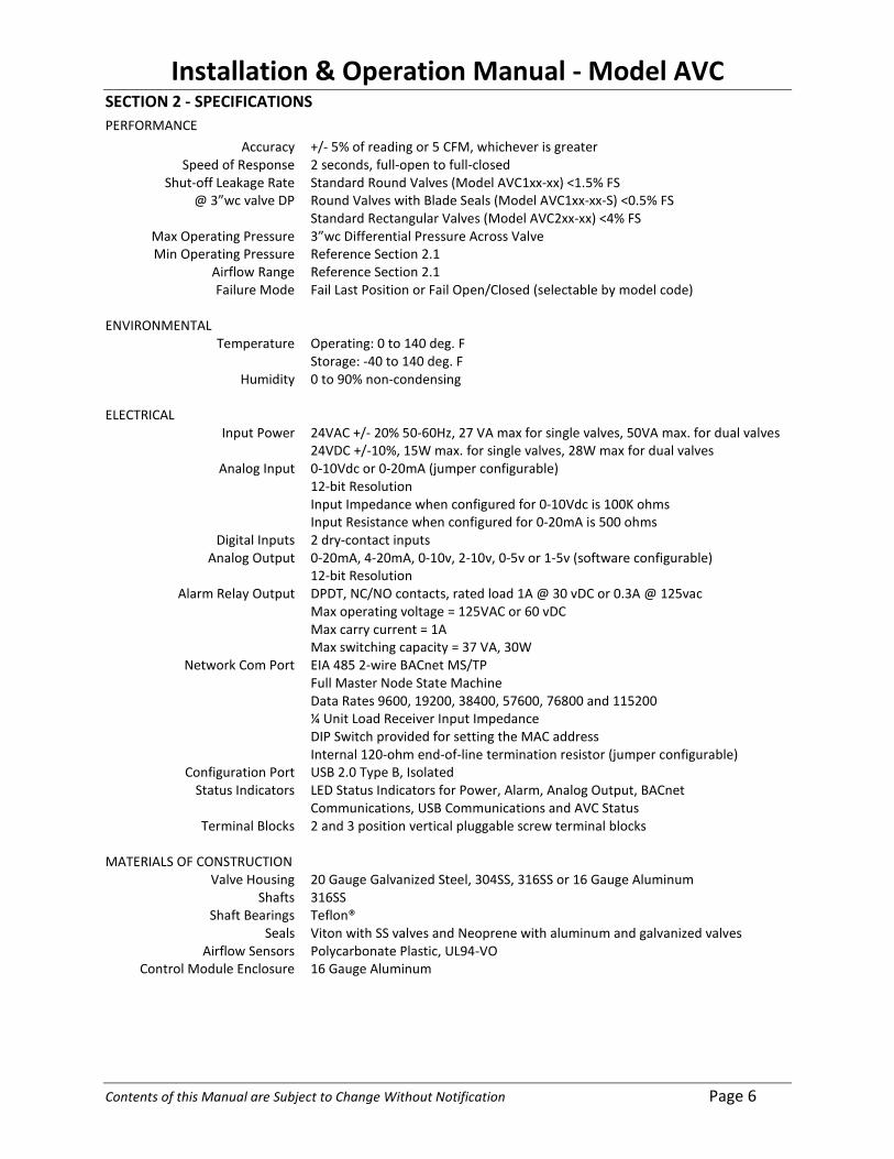
SECTION 2 - SPECIFICATIONS PERFORMANCE
Accuracy +/- 5% of reading or 5 CFM, whichever is greater Speed of Response 2 seconds, full-open to full-closed
Shut-off Leakage Rate @ 3”wc valve DP
Standard Round Valves (Model AVC1xx-xx) <1.5% FS Round Valves with Blade Seals (Model AVC1xx-xx-S) <0.5% FS Standard Rectangular Valves (Model AVC2xx-xx) <4% FS
Max Operating Pressure 3”wc Differential Pressure Across Valve Min Operating Pressure Reference Section 2.1
Airflow Range Reference Section 2.1 Failure Mode Fail Last Position or Fail Open/Closed (selectable by model code)
ENVIRONMENTAL
Temperature Operating: 0 to 140 deg. F Storage: -40 to 140 deg. F
Humidity 0 to 90% non-condensing ELECTRICAL
Input Power 24VAC +/- 20% 50-60Hz, 27 VA max for single valves, 50VA max. for dual valves 24VDC +/-10%, 15W max. for single valves, 28W max for dual valves
Analog Input 0-10Vdc or 0-20mA (jumper configurable) 12-bit Resolution Input Impedance when configured for 0-10Vdc is 100K ohms Input Resistance when configured for 0-20mA is 500 ohms
Digital Inputs 2 dry-contact inputs Analog Output 0-20mA, 4-20mA, 0-10v, 2-10v, 0-5v or 1-5v (software configurable)
12-bit Resolution Alarm Relay Output DPDT, NC/NO contacts, rated load 1A @ 30 vDC or 0.3A @ 125vac
Max operating voltage = 125VAC or 60 vDC Max carry current = 1A Max switching capacity = 37 VA, 30W
Network Com Port EIA 485 2-wire BACnet MS/TP Full Master Node State Machine Data Rates 9600, 19200, 38400, 57600, 76800 and 115200 ¼ Unit Load Receiver Input Impedance DIP Switch provided for setting the MAC address Internal 120-ohm end-of-line termination resistor (jumper configurable)
Configuration Port USB 2.0 Type B, Isolated Status Indicators LED Status Indicators for Power, Alarm, Analog Output, BACnet
Communications, USB Communications and AVC Status Terminal Blocks 2 and 3 position vertical pluggable screw terminal blocks
MATERIALS OF CONSTRUCTION
Valve Housing 20 Gauge Galvanized Steel, 304SS, 316SS or 16 Gauge Aluminum Shafts 316SS
Shaft Bearings Teflon® Seals Viton with SS valves and Neoprene with aluminum and galvanized valves
Airflow Sensors Polycarbonate Plastic, UL94-VO Control Module Enclosure 16 Gauge Aluminum

Installation & Operation Manual - Model AVC
Contents of this Manual are Subject to Change Without Notification Page 7
2.1 Operating Range The operating range of each AccuValve is provided below along with a characteristic curve showing the relationship between the minimum operating pressure and maximum airflow volume as tested in accordance with ANSI/ASHRAE STD 130.
0.00
0.05
0.10
0.15
0.20
0.25
0.30
0.35
0.40
0.45
25 50 75 100 125 150 175 200 225 250 275 300 325
Valv
e DP
("w
c)
Max Airflow (CFM)
0.00
0.05
0.10
0.15
0.20
0.25
0.30
0.35
0.40
0.45
100 150 200 250 300 350 400 450 500 550 600 650 700 750 800
Valv
e DP
("w
c)
Max Airflow (CFM)
0.00
0.05
0.10
0.15
0.20
0.25
0.30
0.35
0.40
0.45
100 200 300 400 500 600 700 800 900 1000 1100 1200 1300
Valv
e DP
("w
c)
Max Airflow (CFM)
6” AccuValve Operating Range: 0-315 CFM Min. Measurement: 30 CFM
8” AccuValve Operating Range: 0-800 CFM Min. Measurement: 80 CFM
10” AccuValve Operating Range: 0-1300 CFM Min. Measurement: 120 CFM

Installation & Operation Manual - Model AVC
Contents of this Manual are Subject to Change Without Notification Page 8
0.00
0.05
0.10
0.15
0.20
0.25
0.30
0.35
0.40
0.45
200 400 600 800 1000 1200 1400 1600 1800
Valv
e DP
("w
c)
Max Airflow (CFM)
0.00
0.05
0.10
0.15
0.20
0.25
0.30
0.35
0.40
0.45
300 600 900 1200 1500 1800 2100 2400 2500
Valv
e DP
("w
c)
Max Airflow (CFM)
0.00
0.05
0.10
0.15
0.20
0.25
0.30
0.35
0.40
0.45
400 800 1200 1600 2000 2400 2800 3200
Valv
e DP
("w
c)
Airflow (CFM)
12” AccuValve Operating Range: 0-1790 CFM Min. Measurement: 180 CFM
14” AccuValve Operating Range: 0-2570 CFM Min. Measurement: 250 CFM
12x18” AccuValve Operating Range: 0-3200 CFM Min. Measurement: 260 CFM

Installation & Operation Manual - Model AVC
Contents of this Manual are Subject to Change Without Notification Page 9
0.00
0.05
0.10
0.15
0.20
0.25
0.30
0.35
0.40
0.45
500 1000 1500 2000 2500 3000 3500 4000
Valv
e DP
("w
c)
Max Airflow (CFM)
0.00
0.05
0.10
0.15
0.20
0.25
0.30
0.35
0.40
0.45
800 1600 2400 3200 4000 4800 5600 6400
Valv
e DP
("w
c)
Max Airflow (CFM)
0.00
0.05
0.10
0.15
0.20
0.25
0.30
0.35
0.40
0.45
1000 2000 3000 4000 5000 6000 7000 8000
Valv
e DP
("w
c)
Max Airflow (CFM)
12x24” AccuValve Operating Range: 0-4000 CFM Min. Measurement: 350 CFM
12x36” AccuValve Operating Range: 0-6400 CFM Min. Measurement: 520 CFM
12x48” AccuValve Operating Range: 0-8000 CFM Min. Measurement: 700 CFM

Installation & Operation Manual - Model AVC
Contents of this Manual are Subject to Change Without Notification Page 10
SECTION 3 – PHYSICAL DIMENSIONS & WEIGHTS
3.1 Round Valve Sizes
3.2 Rectangular Valve Sizes
Valve Model
W L H Weight in. mm in. mm in. mm lbs. kg
AV3200-18 17.88 454 30 762 19 483 43 19.5 AV3200-24 23.88 607 30 762 19 483 49 22.2 AV3200-36 35.88 911 30 762 19 483 97 44.0 AV3200-48 47.88 1216 30 762 19 483 109 49.4
Note: All dimensions are to the “outside” and have a tolerance of +/- .062” (1.6mm).
Valve Model
Dimensions Weight “D” “L” “H” Galv. & SS Aluminum
in. mm in. mm in. mm Lbs. kg Lbs. kg AVC100-06 5.88 149 22 559 10 254 13 5.9 N/A N/A AVC100-08 7.88 200 24 610 13 381 16 7.3 12 5.4 AVC100-10 9.88 250 24 610 15 432 20 9.1 14 6.4 AVC100-12 11.88 300 27 686 17 483 26 11.8 16 7.3 AVC100-14 13.88 350 30 762 19 533 30 13.6 20 9.1
“H”
12” (305mm)
“D” “L”
19” 483mm
“L”
“W”
11.88” 302mm
Installation & Operation Manual - Model AVC
Contents of this Manual are Subject to Change Without Notification Page 11
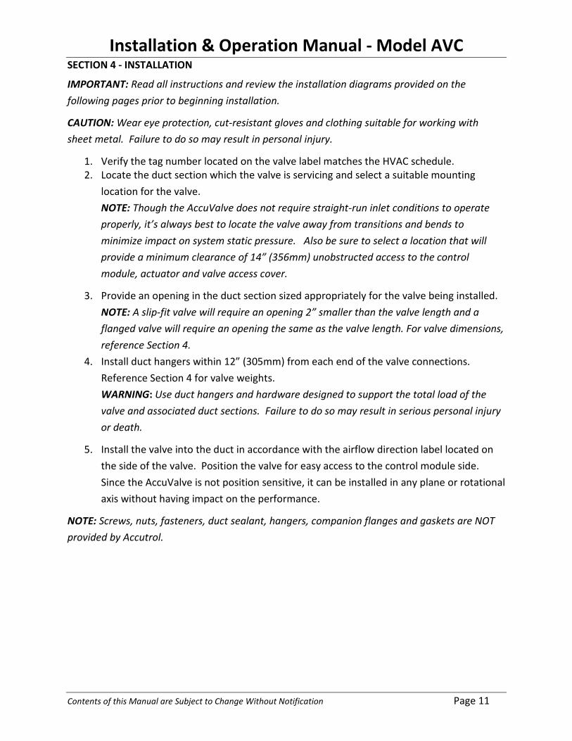
SECTION 4 - INSTALLATION
IMPORTANT: Read all instructions and review the installation diagrams provided on the following pages prior to beginning installation.
CAUTION: Wear eye protection, cut-resistant gloves and clothing suitable for working with sheet metal. Failure to do so may result in personal injury.
1. Verify the tag number located on the valve label matches the HVAC schedule. 2. Locate the duct section which the valve is servicing and select a suitable mounting
location for the valve. NOTE: Though the AccuValve does not require straight-run inlet conditions to operate properly, it’s always best to locate the valve away from transitions and bends to minimize impact on system static pressure. Also be sure to select a location that will provide a minimum clearance of 14” (356mm) unobstructed access to the control module, actuator and valve access cover.
3. Provide an opening in the duct section sized appropriately for the valve being installed. NOTE: A slip-fit valve will require an opening 2” smaller than the valve length and a flanged valve will require an opening the same as the valve length. For valve dimensions, reference Section 4.
4. Install duct hangers within 12” (305mm) from each end of the valve connections. Reference Section 4 for valve weights. WARNING: Use duct hangers and hardware designed to support the total load of the valve and associated duct sections. Failure to do so may result in serious personal injury or death.
5. Install the valve into the duct in accordance with the airflow direction label located on the side of the valve. Position the valve for easy access to the control module side. Since the AccuValve is not position sensitive, it can be installed in any plane or rotational axis without having impact on the performance.
NOTE: Screws, nuts, fasteners, duct sealant, hangers, companion flanges and gaskets are NOT provided by Accutrol.

Installation & Operation Manual - Model AVC
Contents of this Manual are Subject to Change Without Notification Page 12
4.1 Round Valve Installation Diagrams
Standard Slip-fit Valve Secured to Duct with Tek Screws
Standard Slip-fit Valve Secured to Duct with Draw Band Clamps
Flanged Valve “Option –F” Secured to Duct with Companion Flanges and Hardware
INLET
DISCHARGE
Locate duct supports within 12” of each end of the valve.
Locate duct supports within 12” of each end of the valve.
DISCHARGE
INLET
4. Secure using 3/8” bolts, lock washers and nuts.
2. Position valve to provide unobstructed access to the control module, actuator and access panel.
3. Install gaskets and/or duct sealant between the valve flanges and companion flanges.
1. Slip the draw band clamps over each end of the duct.
2. Slip the inlet end of the valve into the duct far enough to allow the valve to be lifted into the duct opening.
3. Slip the discharge end of the valve into the duct engaging valve into duct 1” at each end. 4. Position valve to provide unobstructed access to the control module, actuator and access panel.
6. Secure both ends of valve to the duct using draw band clamps.
2. Slip the discharge end of the valve into the duct engaging valve into duct 1” at each end.
1. Slip the inlet end of valve into the duct far enough to allow the valve to be lifted into the duct opening.
4. Apply duct sealant and secure valve to duct at both ends using tek screws.
3. Position valve to provide unobstructed access to the control module, actuator and access panel.
Locate duct supports within 12” of each end of the valve.
DISCHARGE
INLET
1. Slip the companion flanges over each end of the duct and install to duct as required.
5. For clean air applications, apply foil duct tape over valve/duct seams. For corrosive exhaust applications, apply PTFE adhesive tape over valve/duct seams to protect and seal the draw band clamp gasket from chemical attacks.

Installation & Operation Manual - Model AVC
Contents of this Manual are Subject to Change Without Notification Page 13
4.2 Rectangular Valve Installation Diagrams
Single Valve Sizes -18 and -24
Dual Valve Sizes -36 and -48
Flanged Valve “Option –F”
4. Slip the discharge end of the valve into the duct engaging valve into duct 1” at each end.
3. Slip the inlet end of valve into the duct far enough to allow the valve to be lifted into the duct opening.
5. Secure both ends of valve to duct using tek screws and duct sealant.
Locate duct supports within 12” of each end of the valve.
14” (356mm) Min. Clearance for Access to this Side
INLET DISCHARGE
Air Flow Direction
1. Verify the opening in the duct is properly sized for the valve and installation method being used. Also verify both ends of the duct where the valve is to be attached are true and square before attempting to install valve. If the duct ends are not square and true, do not attempt to install valve as it will not operate properly.
2. Lift valve into position to provide unobstructed access to the control module, actuator and access panel.
Dual valves are provided with integral mounting struts to help support the weight of the valve. In addition to following the installation instructions above, each end of the integral mounting strut shall be secured to the building structure using properly rated hardware and methods in accordance with local building codes.
Mounting Struts
Support Here
3. Install gaskets and/or duct sealant between the valve flanges and companion flanges.
1. Install companion flanges over each end of the duct.
14” (356mm) Min. Clearance for Access to this Side
Locate duct supports within 12” of each end of valve.
INLET DISCHARGE
2. Lift the valve into position to provide unobstructed access to the control module, actuator and access panel.
NOTE: It’s common and acceptable for the sheet metal contractor to fabricate and install flanges onto the AccuValve and ductwork on location. If flanges are fabricated on site, it’s still important to verify both ends of duct are true and square prior to and after installing flanges, otherwise the valve will not operate properly.
4. Secure both ends using 3/8” bolts, lock washers and nuts.
Installation & Operation Manual - Model AVC
Contents of this Manual are Subject to Change Without Notification Page 14
SECTION 5 – WIRING
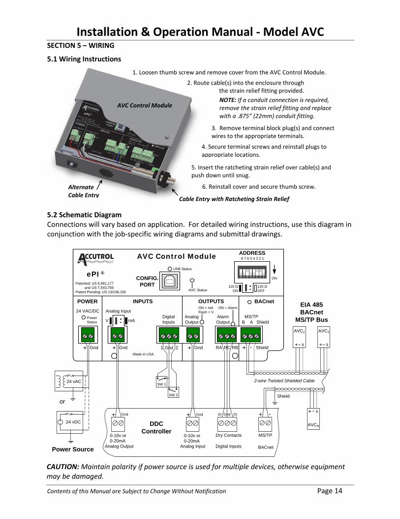
5.1 Wiring Instructions
5.2 Schematic Diagram Connections will vary based on application. For detailed wiring instructions, use this diagram in conjunction with the job-specific wiring diagrams and submittal drawings.
24 VAC/DC
B A
POWER INPUTS OUTPUTS BACnet
Digital Inputs
CONFIG. PORT
USB Status
Analog InputAnalog OutputV mA
ON = mAFlash = V
Alarm Output
ON = Alarm
AVC Status
ADDRESS8 7 6 5 4 3 2 1
ON
120 Ω ON
Shield
Made in USA
1 Gnd 2
MS/TP
Patented: US 6,991,177 and US 7,543,759Patent Pending: US 13/238,155
120 ΩOFF
+ Gnd+ Gnd+ Gnd RA RC RB Shield+ -
Power Status
AVC Control Module
1 2 3 4 5 6 7 8
SW 1
SW 2
or
0-10v or0-20mA
Analog Output
+
0-10v or0-20mA
Analog Input
+ Gnd
DDC Controller
Digital Inputs
Dry Contacts
DI DIGndGnd
Power Source
MS/TP
BACnet
Shield
EIA 485BACnet
MS/TP Bus
2-wire Twisted Shielded Cable
+ -
ePI®
AVC2
+- s
AVC3
+- s
AVCN
+ -
s
24 vAC
24 vDC
1. Loosen thumb screw and remove cover from the AVC Control Module.
AVC Control Module
2. Route cable(s) into the enclosure through the strain relief fitting provided. NOTE: If a conduit connection is required, remove the strain relief fitting and replace with a .875” (22mm) conduit fitting.
4. Secure terminal screws and reinstall plugs to appropriate locations.
3. Remove terminal block plug(s) and connect wires to the appropriate terminals.
5. Insert the ratcheting strain relief over cable(s) and push down until snug.
Cable Entry with Ratcheting Strain Relief
Alternate Cable Entry
6. Reinstall cover and secure thumb screw.
CAUTION: Maintain polarity if power source is used for multiple devices, otherwise equipment may be damaged.

Installation & Operation Manual - Model AVC
Contents of this Manual are Subject to Change Without Notification Page 15
5.3 Address DIP Switch Settings The AVC AccuValve is a BACnet Master Node State machine which operates on a MS/TP bus. Prior to operating on the bus, a valid and unique device address between 0 and 127, referred to as the MAC address, must be set using the ADDRESS DIP Switch located on the AVC Control Module shown below.
Switch positions 1 through 7 are used to set up to 128 different MAC addresses (0-127). Switch position 8 is not used and should remain in the OFF position. Each switch carries a weighted decimal value. The values of each switch in the ON position are summed to equal the MAC address as shown in the examples below. To set the MAC address, set the highest value switch that is less than or equal to the intended MAC address to the ON position, then continue setting the lower numbered switches until the sum of the ON switches equals the intended MAC address.
ON
12345678
1
2
4
816
32
64-
12345678
ON
1248
16
32
64
-
NOTE: It is the responsibility of the BACnet Network Administrator to assign the MAC address to each AVC AccuValve operating on the bus. Duplicate address on a bus segment will result in communication errors.
32 + 4 + 1 = 37 Desired MAC Address = 37
Desired MAC Address = 80 64 + 16 = 80

Installation & Operation Manual - Model AVC
Contents of this Manual are Subject to Change Without Notification Page 16
SECTION 6 – USER INTERFACE & CONFIGURATION
Using a PC you can communicate directly with the AVC AccuValve to configure the controller parameters or locally monitor the AVC performance. All that’s required is a PC with a USB Port, a USB Cable and the AVC UI Software.
6.1 Minimum Requirements • PC with Windows OS (XP, Vista and 7) with USB 2.0 Port • USB Cable Type A/B • AVC Control Module • AVC UI Software
6.2 Installing the AVC UI Software Before starting the install process, close any programs running on the computer.
1. Insert AVC UI Install Disk and run the setup.exe file from the disk.
Note: If installing the AVC UI for the first time on the computer, the USB communications drivers will need to be installed per the following section.
2. The setup wizard will guide you through installation. Follow screen prompts and select the appropriate responses to proceed with installation.
3. Select Program Location and Users that will require access to the AVC UI program.
5. Select Close after installation is complete.
4. Confirm settings are correct and Select Next to proceed with installation.
Installation & Operation Manual - Model AVC
Contents of this Manual are Subject to Change Without Notification Page 17
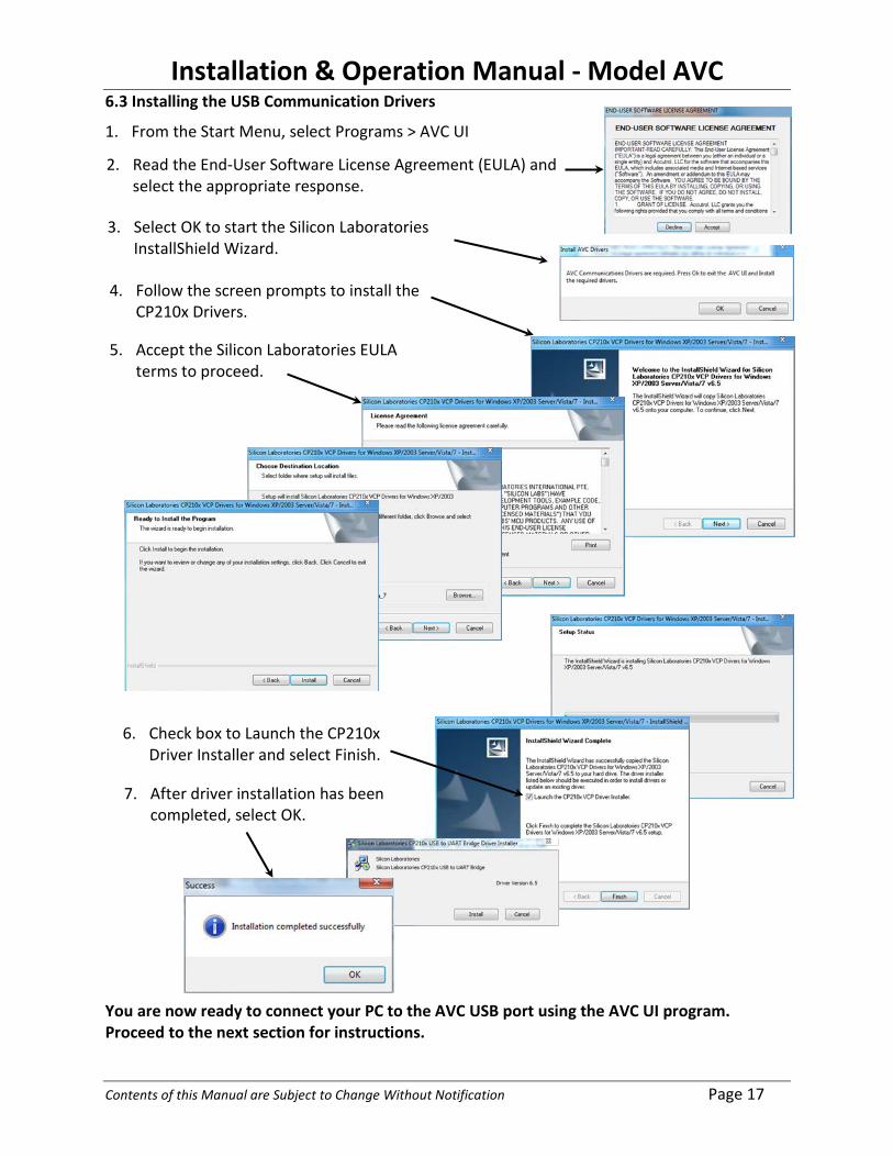
6.3 Installing the USB Communication Drivers
1. From the Start Menu, select Programs > AVC UI
You are now ready to connect your PC to the AVC USB port using the AVC UI program. Proceed to the next section for instructions.
2. Read the End-User Software License Agreement (EULA) and select the appropriate response.
5. Accept the Silicon Laboratories EULA terms to proceed.
6. Check box to Launch the CP210x Driver Installer and select Finish.
7. After driver installation has been
completed, select OK.
4. Follow the screen prompts to install the CP210x Drivers.
3. Select OK to start the Silicon Laboratories InstallShield Wizard.

Installation & Operation Manual - Model AVC
Contents of this Manual are Subject to Change Without Notification Page 18
6.4 Connecting the PC to the AVC Control Module Once the UI Software and USB drivers have been successfully installed on your PC, remove the cover from the AVC Control Module and connect the PC to the AVC as shown below.
6.5 AVC UI Software To open the AVC UI application either double-click on the desktop shortcut created during installation, or from the Start Menu select Programs > AVC UI
Select the appropriate COM port for the AVC then select Connect. Note: The password field will automatically populate with a valid password.
Note: if you’re not sure which COM port your computer is using for the AVC, then unplug the AVC from USB port and view the drop-down list noting the COM ports that are included in the list. Now plug the AVC into USB port and view the drop-down list. The new COM port added to the list is the AVC COM port.
PC with AVC UI Software
USB Cable Type A/B
AVC AccuValve

Installation & Operation Manual - Model AVC
Contents of this Manual are Subject to Change Without Notification Page 19
6.6 AVC UI Dashboard The AVC Dashboard is comprised of several objects which provide a visual indication of the real-time operating status of the AVC. These objects also provide an intuitive graphical user interface for field-programing the AVC. Each of the Dashboard objects can be closed by clicking on the x in the upper right corner of the object. The Dashboard objects can also be rearranged by selecting the box in the lower left corner and dragging to the desired location.
6.6.1 Airflow Volume Gauge The Airflow Volume Gauge provides the most critical real-time operating parameters of the AVC. The Airflow Volume Gauge is an “information only” object; therefore no field programming can be accessed through the Airflow Volume Gauge.
Note 1: Red Alarm Band indicates Alarm is Active, Gray band indicates alarm is Inactive.
Airflow Volume Gauge
Strip Chart
Control Diagram
Airflow Setpoint Gauge Airflow Output Gauge
Control Output Gauge
Valve Position Gauge
Alarms Diagra
Airflow Setpoint +/- 5% of Reading
High Alarm Limit Note 1
Low Alarm Limit Note 1
Airflow Measurement (Analog Scale)
Airflow Setpoint (Digital Scale)
Operating Range of Valve
Airflow Measurement (Digital Scale)
Airflow Volume Units
Task Bar

Installation & Operation Manual - Model AVC
Contents of this Manual are Subject to Change Without Notification Page 20
6.6.2 Airflow Setpoint Gauge The Airflow Setpoint Gauge displays the Airflow Setpoint Value, the Airflow Setpoint Range and the Airflow Setpoint Source. Access to the Setpoint Source Configuration Menu is provided by selecting the “SOURCE” button.
6.6.2.1 Airflow Setpoint Source Selection There are three different input sources which can be selected for the Airflow Setpoint; Analog Input (AI-1), Dry Contact Input (DI-1, DI-2) and Communications (BACnet). The following examples show how to configure the AVC for each of these different input source types.
6.6.2.1.1 Selecting Analog Input (AI-1) as the Airflow Setpoint Input Source After selecting the “SOURCE” button on the AIRFLOW SETPOINT gauge, follow the instructions provided below to configure the Analog Input as the Airflow Setpoint Source.
Select “SOURCE” to Open Configuration Window
Airflow Setpoint Range Indicated by Gauge Face Values
Airflow Setpoint Value
1. Select “ANALOG INPUT”
Present Setpoint Source
2. Select either “Voltage” or “Current” (depending on your application).
3. Enter Analog Input Range and Airflow Volume Range for Scaling.
NOTE: Verify the Shunt Position on the Control Module’s Analog Input Agrees with Selection.
4. Select “Update Controller” to Save Changes.
Installation & Operation Manual - Model AVC
Contents of this Manual are Subject to Change Without Notification Page 21
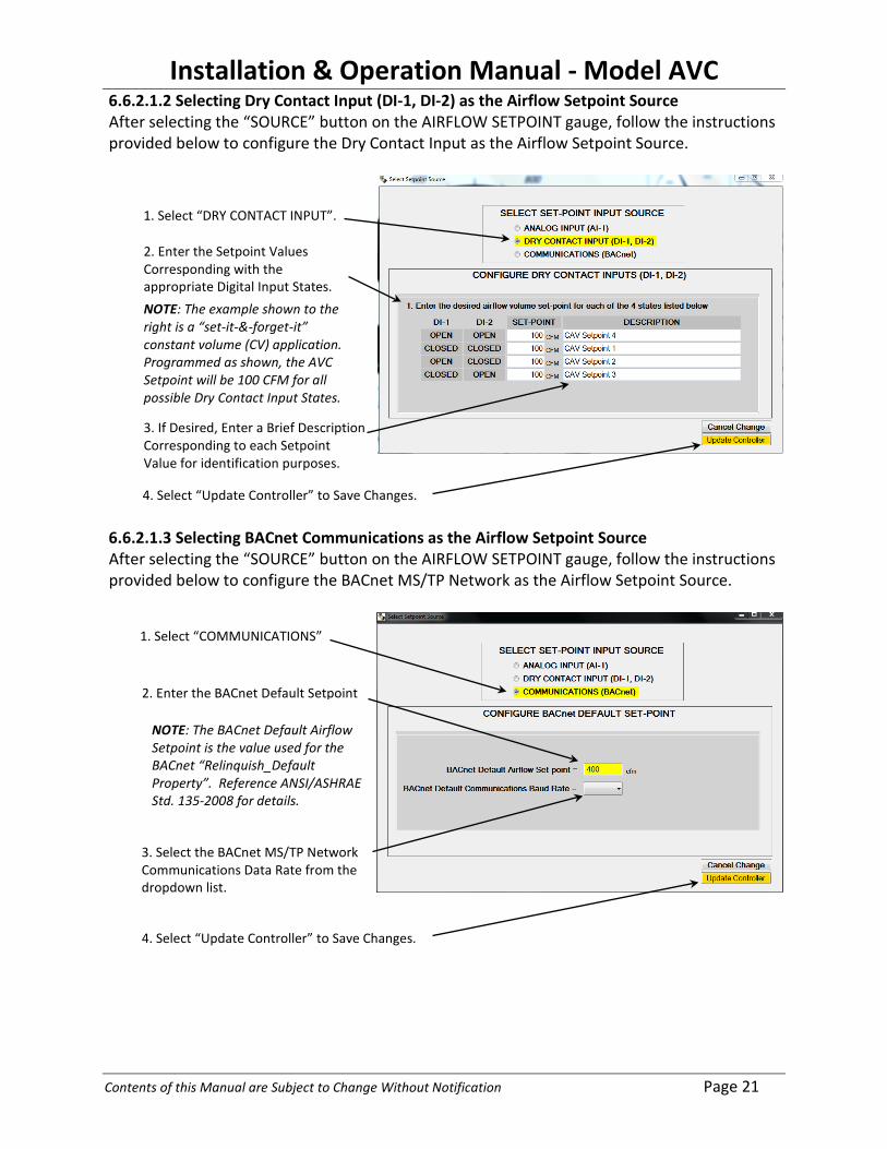
6.6.2.1.2 Selecting Dry Contact Input (DI-1, DI-2) as the Airflow Setpoint Source After selecting the “SOURCE” button on the AIRFLOW SETPOINT gauge, follow the instructions provided below to configure the Dry Contact Input as the Airflow Setpoint Source.
6.6.2.1.3 Selecting BACnet Communications as the Airflow Setpoint Source After selecting the “SOURCE” button on the AIRFLOW SETPOINT gauge, follow the instructions provided below to configure the BACnet MS/TP Network as the Airflow Setpoint Source.
1. Select “DRY CONTACT INPUT”.
2. Enter the Setpoint Values Corresponding with the appropriate Digital Input States.
4. Select “Update Controller” to Save Changes.
3. If Desired, Enter a Brief Description Corresponding to each Setpoint Value for identification purposes.
NOTE: The example shown to the right is a “set-it-&-forget-it” constant volume (CV) application. Programmed as shown, the AVC Setpoint will be 100 CFM for all possible Dry Contact Input States.
1. Select “COMMUNICATIONS”
2. Enter the BACnet Default Setpoint
NOTE: The BACnet Default Airflow Setpoint is the value used for the BACnet “Relinquish_Default Property”. Reference ANSI/ASHRAE Std. 135-2008 for details.
3. Select the BACnet MS/TP Network Communications Data Rate from the dropdown list.
4. Select “Update Controller” to Save Changes.
Installation & Operation Manual - Model AVC
Contents of this Manual are Subject to Change Without Notification Page 22
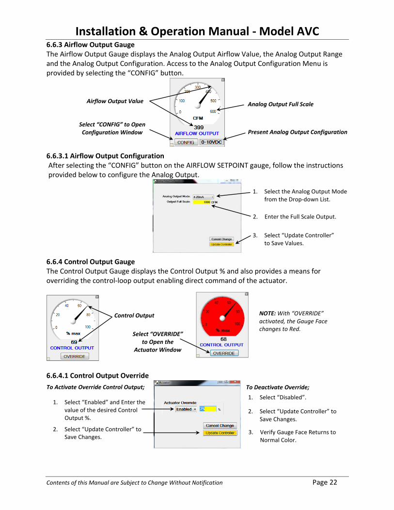
6.6.3 Airflow Output Gauge The Airflow Output Gauge displays the Analog Output Airflow Value, the Analog Output Range and the Analog Output Configuration. Access to the Analog Output Configuration Menu is provided by selecting the “CONFIG” button.
6.6.3.1 Airflow Output Configuration After selecting the “CONFIG” button on the AIRFLOW SETPOINT gauge, follow the instructions provided below to configure the Analog Output.
6.6.4 Control Output Gauge The Control Output Gauge displays the Control Output % and also provides a means for overriding the control-loop output enabling direct command of the actuator.
6.6.4.1 Control Output Override
Select “CONFIG” to Open Configuration Window
Analog Output Full Scale Airflow Output Value
Present Analog Output Configuration
1. Select the Analog Output Mode from the Drop-down List.
2. Enter the Full Scale Output.
3. Select “Update Controller” to Save Values.
Control Output
Select “OVERRIDE” to Open the
Actuator Window
NOTE: With “OVERRIDE” activated, the Gauge Face changes to Red.
To Activate Override Control Output;
2. Select “Update Controller” to Save Changes.
To Deactivate Override; 1. Select “Disabled”.
1. Select “Enabled” and Enter the value of the desired Control Output %.
2. Select “Update Controller” to Save Changes.
3. Verify Gauge Face Returns to Normal Color.
Installation & Operation Manual - Model AVC
Contents of this Manual are Subject to Change Without Notification Page 23
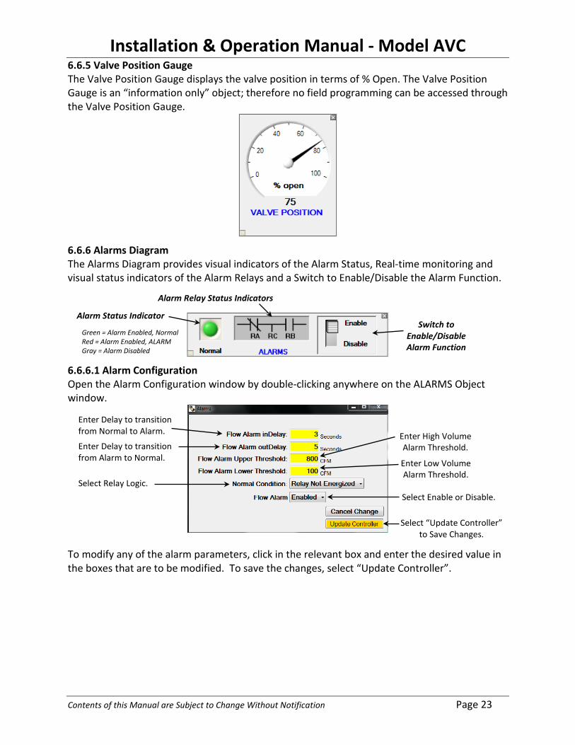
6.6.5 Valve Position Gauge The Valve Position Gauge displays the valve position in terms of % Open. The Valve Position Gauge is an “information only” object; therefore no field programming can be accessed through the Valve Position Gauge.
6.6.6 Alarms Diagram The Alarms Diagram provides visual indicators of the Alarm Status, Real-time monitoring and visual status indicators of the Alarm Relays and a Switch to Enable/Disable the Alarm Function.
6.6.6.1 Alarm Configuration Open the Alarm Configuration window by double-clicking anywhere on the ALARMS Object window.
To modify any of the alarm parameters, click in the relevant box and enter the desired value in the boxes that are to be modified. To save the changes, select “Update Controller”.
Green = Alarm Enabled, Normal Red = Alarm Enabled, ALARM Gray = Alarm Disabled
Alarm Status Indicator
Alarm Relay Status Indicators
Switch to Enable/Disable Alarm Function
Enter Delay to transition from Normal to Alarm.
Enter Delay to transition from Alarm to Normal.
Select Relay Logic. Select Enable or Disable.
Enter High Volume Alarm Threshold.
Enter Low Volume Alarm Threshold.
Select “Update Controller” to Save Changes.

Installation & Operation Manual - Model AVC
Contents of this Manual are Subject to Change Without Notification Page 24
6.6.7 Control Diagram Diagram The Control Diagram provides real-time data of all parameters associated with the Closed-Loop Control Function. Configurable parameters are displayed in the white boxes and non-configurable parameters are displayed in gray boxes. A brief description of each control parameter is provided below the Control Diagram.
• SETPOINT: The SETPOINT value is provided by the “Setpoint Source” and is not a
configurable parameter in the CONTROL OBJECT. • OFFSET: The OFFSET value is a configurable parameter which is normally used in tracking
pair applications. The sum of the OFFSET and SETPOINT make up the control loop SETPOINT value. Polarity can be either positive or negative, based on application.
• % DEADBAND: The % DEADBAND value is a configurable parameter which is applied as a percentage of the SETPOINT value. The purpose of the DEADBAND is to improve control loop stability by holding the control output constant until the ERROR exceeds the % DEADBAND.
• MEASURED: The MEASURED value is the calibrated airflow measurement provided by the airflow sensors and is not a configurable parameter. The airflow measurement value is the process variable which closes the feedback loop.
• ERROR: The control ERROR is difference between the SETPOINT and MEASURED values. The control ERROR is input to the PI algorithm which generates the control output.
• P & I: The AVC utilizes a parallel PI algorithm which includes two configurable parameters, P (Proportional Gain) and I (Integral). Both of these parameters act in parallel on the same error then are combined to generate the control output signal. Increasing the P term (Proportional Gain) makes the control loop more sensitive and less stable. The P term, which has no units, is normally a decimal value between 1.00 and 3.00. The I term, sometimes referred to as “automatic reset”, increases the control output by the integral of the error. The I term is normally between 30 and 40.
• OUTPUT LIMITS: The UPPER and LOWER OUTPUT LIMITS are configurable parameters which are essentially clamps for the control output. Normally the LOWER limit is set to 0% and the UPPER limit is set to 100%. The OUTPUT LIMITS are only used for applications that would benefit from limiting the control output thereby preventing the valve from fully closing and/or fully opening.
• CONTROL OUTPUT: The CONTROL OUTPUT % is generated by the PI control loop and is used to modulate the valve actuator resulting in a reduced error between the setpoint and measurement.
Installation & Operation Manual - Model AVC
Contents of this Manual are Subject to Change Without Notification Page 25
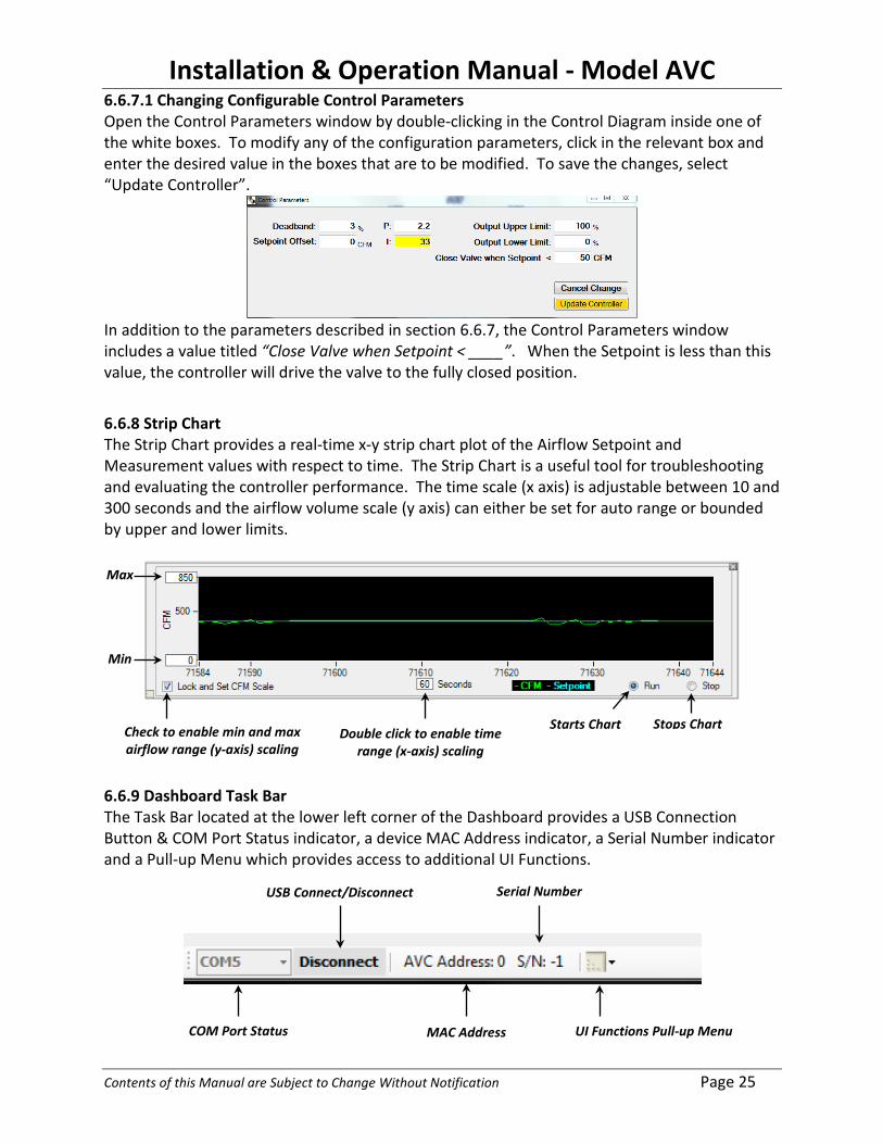
6.6.7.1 Changing Configurable Control Parameters Open the Control Parameters window by double-clicking in the Control Diagram inside one of the white boxes. To modify any of the configuration parameters, click in the relevant box and enter the desired value in the boxes that are to be modified. To save the changes, select “Update Controller”.
In addition to the parameters described in section 6.6.7, the Control Parameters window includes a value titled “Close Valve when Setpoint < ____”. When the Setpoint is less than this value, the controller will drive the valve to the fully closed position.
6.6.8 Strip Chart The Strip Chart provides a real-time x-y strip chart plot of the Airflow Setpoint and Measurement values with respect to time. The Strip Chart is a useful tool for troubleshooting and evaluating the controller performance. The time scale (x axis) is adjustable between 10 and 300 seconds and the airflow volume scale (y axis) can either be set for auto range or bounded by upper and lower limits.
6.6.9 Dashboard Task Bar The Task Bar located at the lower left corner of the Dashboard provides a USB Connection Button & COM Port Status indicator, a device MAC Address indicator, a Serial Number indicator and a Pull-up Menu which provides access to additional UI Functions.
Check to enable min and max airflow range (y-axis) scaling
Double click to enable time range (x-axis) scaling
Starts Chart Stops Chart
Max
Min
USB Connect/Disconnect
MAC Address
Serial Number
UI Functions Pull-up Menu COM Port Status
Installation & Operation Manual - Model AVC
Contents of this Manual are Subject to Change Without Notification Page 26
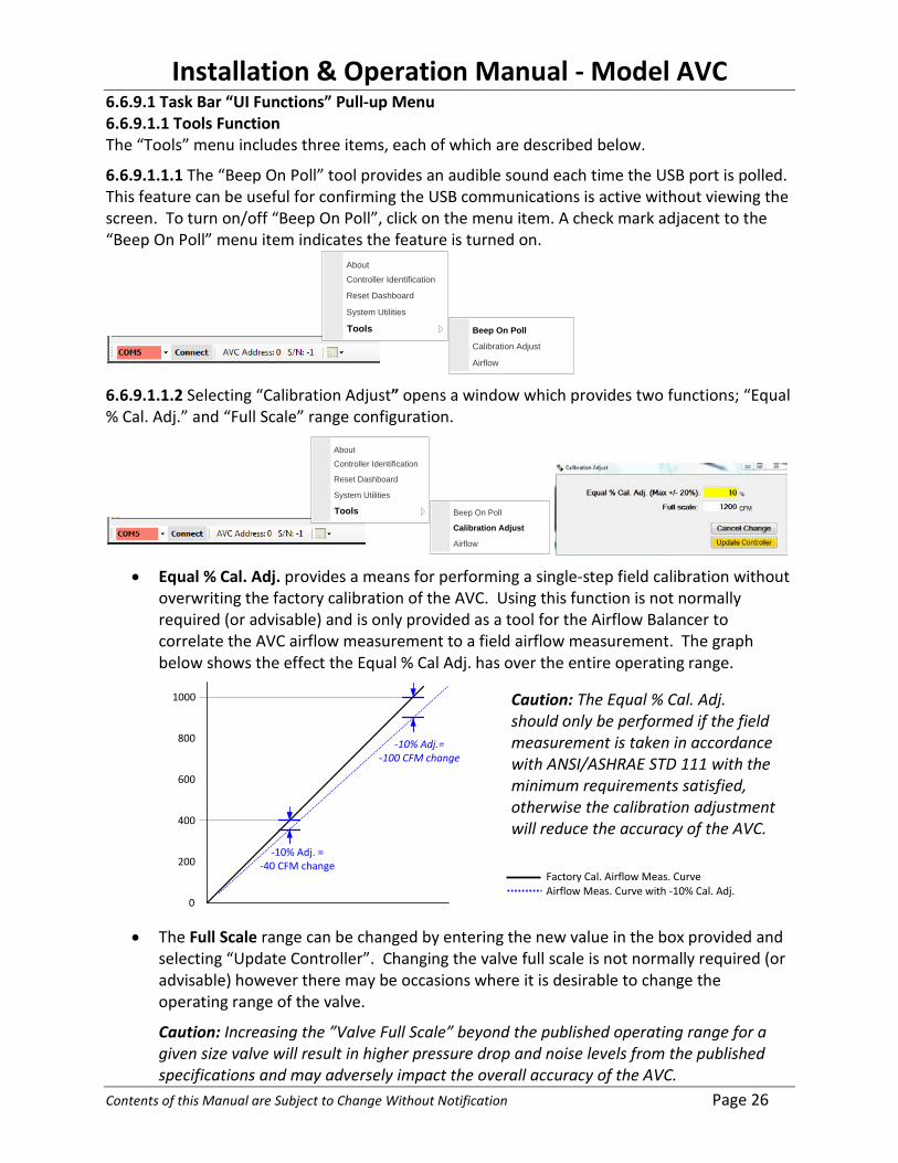
6.6.9.1 Task Bar “UI Functions” Pull-up Menu 6.6.9.1.1 Tools Function The “Tools” menu includes three items, each of which are described below.
6.6.9.1.1.1 The “Beep On Poll” tool provides an audible sound each time the USB port is polled. This feature can be useful for confirming the USB communications is active without viewing the screen. To turn on/off “Beep On Poll”, click on the menu item. A check mark adjacent to the “Beep On Poll” menu item indicates the feature is turned on.
Beep On Poll
Calibration Adjust
Airflow
Controller Identification
Reset Dashboard
System Utilities
Tools
About
6.6.9.1.1.2 Selecting “Calibration Adjust” opens a window which provides two functions; “Equal % Cal. Adj.” and “Full Scale” range configuration.
Beep On Poll
Calibration Adjust
Airflow
Controller Identification
Reset Dashboard
System Utilities
Tools
About
• Equal % Cal. Adj. provides a means for performing a single-step field calibration without
overwriting the factory calibration of the AVC. Using this function is not normally required (or advisable) and is only provided as a tool for the Airflow Balancer to correlate the AVC airflow measurement to a field airflow measurement. The graph below shows the effect the Equal % Cal Adj. has over the entire operating range.
-10% Adj.= -100 CFM change
-10% Adj. =-40 CFM change
1000
400
800
600
200
0 • The Full Scale range can be changed by entering the new value in the box provided and
selecting “Update Controller”. Changing the valve full scale is not normally required (or advisable) however there may be occasions where it is desirable to change the operating range of the valve.
Caution: Increasing the ”Valve Full Scale” beyond the published operating range for a given size valve will result in higher pressure drop and noise levels from the published specifications and may adversely impact the overall accuracy of the AVC.
Caution: The Equal % Cal. Adj. should only be performed if the field measurement is taken in accordance with ANSI/ASHRAE STD 111 with the minimum requirements satisfied, otherwise the calibration adjustment will reduce the accuracy of the AVC.
Factory Cal. Airflow Meas. Curve Airflow Meas. Curve with -10% Cal. Adj.

Installation & Operation Manual - Model AVC
Contents of this Manual are Subject to Change Without Notification Page 27
6.6.9.1.1.3 Selecting “Airflow” provides viewing access to the AVC’s real-time airflow measurement data window. In addition to providing the factory calibration constants, the Airflow Window also provides the real-time vortex shedding frequency measurement in each chamber of the AccuValve, which can be a useful troubleshooting tool. This window does not provide access for making changes to the calibration data.
6.6.9.1.2 System Utilities The “System Utilities” window is used to save and restore the AVC configuration data. The buttons located below the “Controller Memory” heading are used to save and recall data to and from the AVC’s nonvolatile memory. The buttons located below the “Controller Configuration” heading are used to save and recall data files between the PC and the AVC’s RAM memory.
Controller Identification
Reset Dashboard
System UtilitiesTools
About
6.6.9.1.3 Reset Dashboard Selecting “Reset Dashboard” will restore Dashboard objects to their factory default positions.
Installation & Operation Manual - Model AVC
Contents of this Manual are Subject to Change Without Notification Page 28
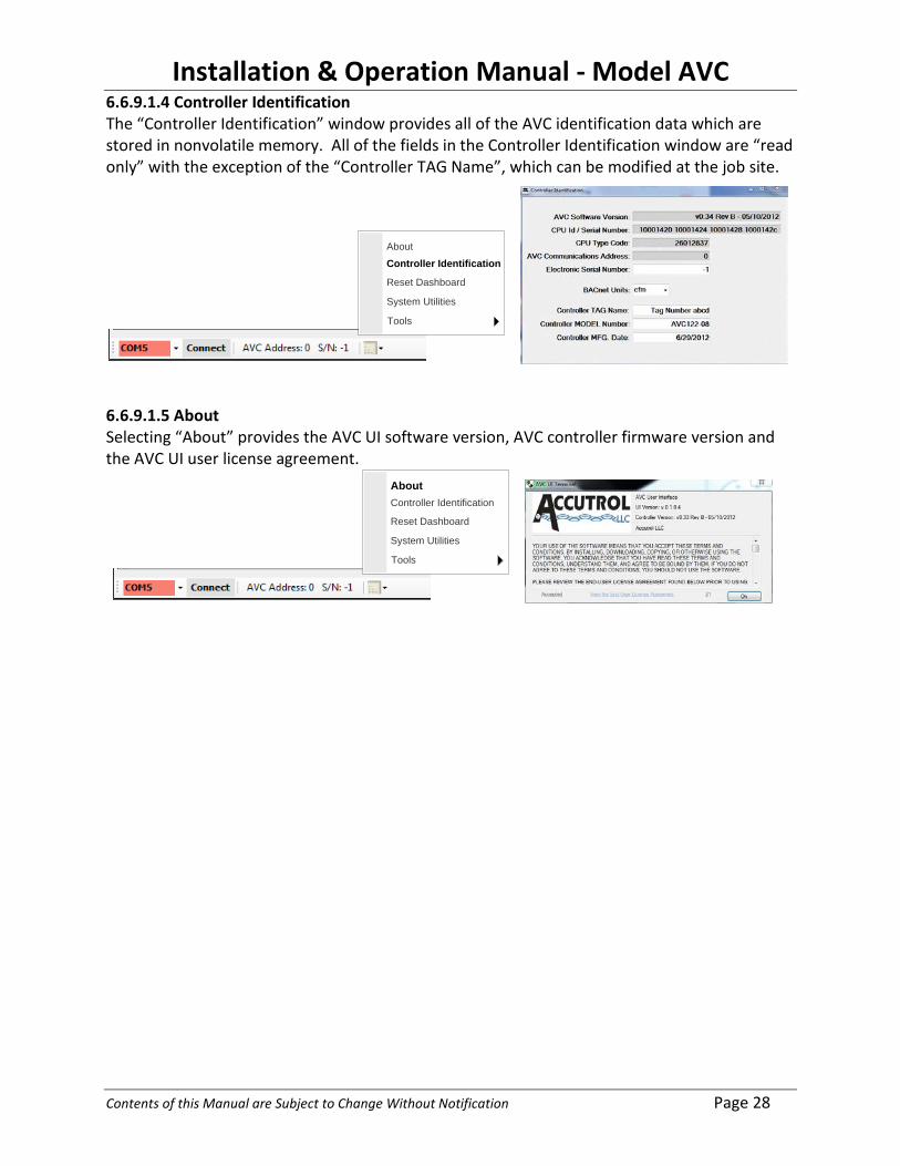
6.6.9.1.4 Controller Identification The “Controller Identification” window provides all of the AVC identification data which are stored in nonvolatile memory. All of the fields in the Controller Identification window are “read only” with the exception of the “Controller TAG Name”, which can be modified at the job site.
Controller Identification
Reset Dashboard
System Utilities
Tools
About
6.6.9.1.5 About Selecting “About” provides the AVC UI software version, AVC controller firmware version and the AVC UI user license agreement.
Controller Identification
Reset Dashboard
System Utilities
Tools
About

Installation & Operation Manual - Model AVC
Contents of this Manual are Subject to Change Without Notification Page 29
SECTION 7 – BACnet
7.1 BACnet Objects The AVC AccuValve supports a collection of BACnet-visible objects. In addition to a Device object whose instance is programmed by writing to the Object_Identifier of the wildcard Device Instance, the AVC supports several standard object types as described below. The following table defines the visible objects. The PV column indicates whether the Present_Value is Read only, Writable or Commandable.
# Obj. I.D. Description PV Units 1 DExxx Device Object x 2 AI1 Measured Airflow Volume R CFM 3 AI2 Analog Airflow Setpoint R CFM 4 AI3 Airflow Actuator Position Feedback R % 5 AV1 Airflow Setpoint W CFM 6 AV2 Unsubscribed COV Interval W Sec 7 AO1 Airflow Actuator Position C % 8 BI1 Alarm: 0=normal, 1=alarm R 9 MSI1 DI states 1..4 R
10 MSI2 CAV Input Selector: 1=AI2, 2=MSI1, 3=AV1 R 11 MSI3 System Units: 1=CFM, 2=CMS, 3=CMM,4=CMH, 5=LPS, 6=LPM W
In general the standard AI, AV, AO, BI, and MSI objects support required properties for those object types. Object_Name is writable with provision for 64 character maximum length names. BI Inactive_Text and Active_Text, and MSI State_Text are writable. Device_Type is fixed and not writable.
Each AI/AV/AO object’s Units property automatically changes to the appropriate unit for US or SI measurement based on the value of MSI3. Internally Present_Values are stored in US units and converted to/from SI units only when read or written.
Standard object property values other than Present_Value shall be derived as follows: • Object_Identifier: generated automatically from request • Object_Type: generated automatically from request • Object_Name: writable • Polarity: always NORMAL • Units: Reference Table above, #11. • State_Text, Inactive_Text, Active_Text: writable • Status_Flags: always FALSE,FALSE,FALSE,FALSE • Event_State: always NORMAL • Out_Of_Service: always FALSE
The internal Airflow Control loop dictates the Airflow Actuator Position (AO1) at a priority of 10. Devices external to the AVC that need to control the actuator directly shall use higher priority levels (9, 8, 7 etc.). The AI/AV/AO objects shall all support the COV_INCREMENT property which shall also be writable.

Installation & Operation Manual - Model AVC
Contents of this Manual are Subject to Change Without Notification Page 30
7.2 Command ability Only object AO1 supports BACnet command prioritization for writable Present_Values. Those objects shall include the Priority_Array and Relinquish_Default properties and their corresponding behaviors with respect to controlling the value written to the object’s Present_Value. The AVC proactively manages each of these Priority_Arrays and updates the Present_Value accordingly.
7.3 Unsubscribed COV The AV2 object Present_Value shall specify an interval in whole seconds at which the AVC shall periodically issue Unsubscribed COV Notifications as local segment broadcasts. An AV2 value of zero shall disable this behavior. When non-zero, the Unsubscribed COV shall also be issued if the Present_Value of any object AI1, AI2, AI3, AV1, or AO1 changes by more than the COV_INCREMENT for the corresponding object. If COV_INCREMENT is zero for a given object, it shall also disable Unsubscribed COV for that object, even if AV2 is non-zero.
7.4 COV The AVC supports a pool of 40 subscription resources that may be applied to track COV subscriptions for change of value of any of the objects AI1, AI2, AI3, AV1, or AO1. Each subscription shall include the objectID, the last transmitted value, the remaining subscription lifetime in seconds, the subscriber process ID, a flag indicating whether confirmed or unconfirmed notifications should be used and the (network number, MAC address) of the subscriber.

Installation & Operation Manual - Model AVC
Contents of this Manual are Subject to Change Without Notification Page 31
7.5 BACnet Protocol Implementation Conformance Statement (PICS)
Date: Vendor Name: Accutrol LLC Product Name: AVC Product Model Number: AVC Product Family Application Software Version: Firmware Revision: BACnet Protocol Revision:
Product Description: The AVC is a product family of airflow control valves incorporating a unitary valve-mounted controller designed specifically for the AccuValve® airflow control valve.
BACnet Standardized Device Profile: BACnet Operator Workstation (B-OWS) BACnet Advanced Operator Workstation (B-AWS) BACnet Operator Display (B-OD) BACnet Building Controller (B-BC) BACnet Advanced Application Controller (B-AAC) BACnet Application Specific Controller (B-ASC) BACnet Smart Sensor (B-SS) BACnet Smart Actuator (B-SA)
List all BACnet Interoperability Building Blocks Supported Specification BIBB Name Supported BIBB
K.1.2 Data Sharing – ReadProperty-B DS-RP-B K.1.4 Data Sharing – ReadPropertyMultiple-B DS-RPM-B K.1.8 Data Sharing – WriteProperty-B DS-WP-B
K.1.12 Data Sharing – COV-B DS-COV-B K.1.16 Data Sharing – COV-Unsolicited-B DS-COVU-B K.5.2 Device Management – Dynamic Device Binding-B DM-DDB-B K.5.4 Device Management – DynamicObject Binding-B DM-DOB-B K.5.6 Device Management – DeviceCommunicationControl-B DM-DCC-B
K.5.16 Device Management – DynamicReinitializeDevice-B DM-RD-B
Segmentation Capability: Able to transmit segmented messages Window Size Able to receive segmented messages Window Size

Installation & Operation Manual - Model AVC
Contents of this Manual are Subject to Change Without Notification Page 32
Standard Object Types Supported: Object Create
Object Service
Delete Object Service
Optional Properties Supported
Writeable Properties
DE Device Object No No Active_COV_Subscriptions Object_Name Description Max_Master Max_Info_Frames
AI Analog Input No No COV_Increment Object_Name AO Analog Output No No COV_Increment Object_Name
Relinquish_Default AV Analog Value No No COV_Increment Object_Name
Present_Value BI Binary Input
No No Inactive_Text
Active_Text Object_Name Inactive_Text Active_Text Alarm_Value
MSI Multi State Input
No No State_Text Object_Name Present_Value
Data Link Layer Options: BACnet IP, (Annex J) BACnet IP, (Annex J), Foreign Device ISO 8802-3, Ethernet (Clause 7) ATA 878.1, 2.5 Mb. ARCNET (Clause 8) ATA 878.1, EIA-485 ARCNET (Clause 8), baud rate(s): MS/TP master (Clause 9), baud rate(s): 9600, 19200, 38400, 76800, 115200 MS/TP slave (Clause 9), baud rate(s): Point-To-Point, EIA 232 (Clause 10), baud rate(s): Point-To-Point, modem, (Clause 10), baud rate(s): LonTalk, (Clause 11), medium: BACnet/ZigBee (ANNEX O) Other:
Device Address Binding: Is static device binding supported? (This is currently necessary for two-way communication with MS/TP slaves and certain other devices.) Yes No
Networking Options: Router, Clause 6 - List all routing configurations, e.g., ARCNET-Ethernet, Ethernet-MS/TP, etc. Annex H, BACnet Tunneling Router over IP BACnet/IP Broadcast Management Device (BBMD) Does the BBMD support registrations by Foreign Devices? Yes No Does the BBMD support network address translation? Yes No
Installation & Operation Manual - Model AVC
Contents of this Manual are Subject to Change Without Notification Page 33
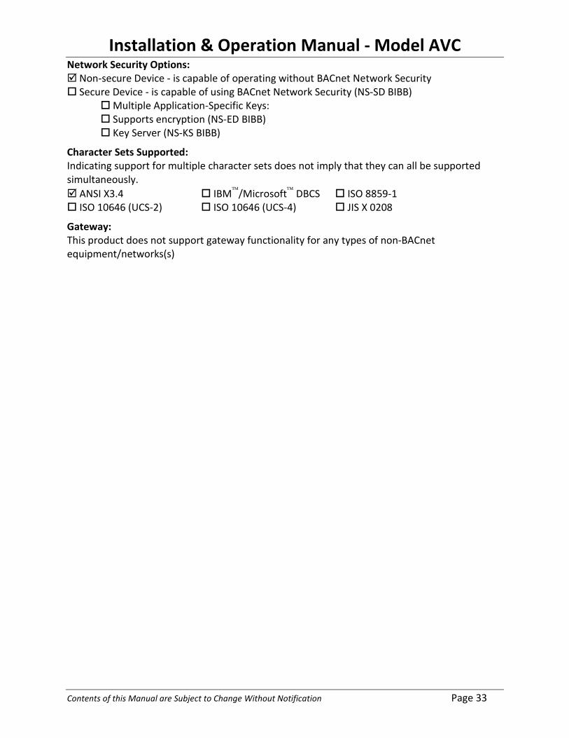
Network Security Options: Non-secure Device - is capable of operating without BACnet Network Security Secure Device - is capable of using BACnet Network Security (NS-SD BIBB) Multiple Application-Specific Keys: Supports encryption (NS-ED BIBB) Key Server (NS-KS BIBB)
Character Sets Supported: Indicating support for multiple character sets does not imply that they can all be supported simultaneously. ANSI X3.4 IBM/Microsoft DBCS ISO 8859-1 ISO 10646 (UCS-2) ISO 10646 (UCS-4) JIS X 0208
Gateway: This product does not support gateway functionality for any types of non-BACnet equipment/networks(s)

Installation & Operation Manual - Model AVC
Contents of this Manual are Subject to Change Without Notification Page 34
SECTION 8 – MAINTENANCE
Scheduled maintenance for the AVC is not required; however each AccuValve does include an access cover which can be removed to inspect the airflow sensors if desired.
8.1 Round Valve Access Cover
CAUTION: Wear eye protection, cut-resistant gloves and clothing suitable for working with sheet metal. Failure to do so may result in personal injury.
8.1.1 Loosen the 3/8” bolt enough to allow the access door to slide forward.
CAUTION: If the bolt is removed from the captive nut, the access cover can spring open possibly causing injury. 8.1.2 Using two hands; squeeze the access cover and slide it forward over the valve enough to uncover the access opening. 8.1.3 Once the cover is slid forward or removed, the airflow sensors can be visually inspected. 8.1.4 When inspection is complete, slide the access cover over the opening, being careful not to damage gasket in the process. 8.1.5 Verify the access cover is in position to completely cover the opening. Secure cover in place by tightening the 3/8” bolt using care not to over tighten.
Access Cover Loosen 3/8” Bolt
Slide Cover Forward or Remove Carefully
Sensors

Installation & Operation Manual - Model AVC
Contents of this Manual are Subject to Change Without Notification Page 35
8.2 Rectangular Valve Access Cover
CAUTION: Wear eye protection, cut-resistant gloves and clothing suitable for working with sheet metal. Failure to do so may result in personal injury.
8.2.1 The access cover is secured to the valve using (12) Tek-Screws. Remove the (12) Tek-Screws using a 5/16” socket and put the screws aside for reinstalling the cover later.
8.2.2 Remove the access cover from the valve.
8.2.3 Once the cover is removed the sensors are accessible for inspection.
8.2.4 When inspection is complete, place the access cover in position and secure using the (12) screws previously removed.
Access Cover
Remove (12) Screws
Sensor Sensor

Installation & Operation Manual - Model AVC
Contents of this Manual are Subject to Change Without Notification A
APPENDIX A: DOCUMENT REVISION HISTORY
New Release: July 2012 New Filename: AVC MANUAL-JULY 2012.DOC
Section Description of Change
Revision History New Revision: New Filename:
Section Description of Change