high airflow pressure loading actuator - uf …€¦ · · 2017-03-03high airflow pressure...
TRANSCRIPT
Instruction Manual August 22, 2016
High Airflow Pressure Loading Actuator
Powell Family Structures & Materials Laboratory
Professor: David O. Prevatt, PhD

University of Florida MultiHazard Research Laboratory
High Airflow Pressure Loading ActuatorOperation Manual
ii
TABLE OF CONTENTS
1 Background ........................................................................................................................... 1
1.1 EQUIPMENT SPECIFICATIONS AND CAPABILITIES ............................................................................................. 2
2 Operation Instructions ......................................................................................................... 6
2.1 POWERING ON.................................................................................................................................................. 6 2.1.1 Step 1 – Power On VFDs ....................................................................................................................... 6 2.1.2 Step 2 – Enter VFD Run Mode .............................................................................................................. 7 2.1.3 Step 3 – Verify VFD Run Mode .............................................................................................................. 7 2.1.4 Step 4 – Enable Remote Access of VFD ................................................................................................. 8 2.1.5 Step 5 – Power On Servo Motor ............................................................................................................ 8
2.2 LABVIEW INTERFACE ..................................................................................................................................... 9 2.2.1 Step 1 – Open LabVIEW HAPLA Testing Interface ............................................................................... 9 2.2.2 Step 2 – Select HAPLA Operation Mode ............................................................................................. 10 2.2.3 Step 3 – Select File Save Location ....................................................................................................... 12 2.2.4 Step 4 – Activate Data Recording ........................................................................................................ 13
2.3 POWERING DOWN .......................................................................................................................................... 13 2.3.1 Checklist .............................................................................................................................................. 13
University of Florida MultiHazard Research Laboratory
High Airflow Pressure Loading ActuatorOperation Manual
Page 1
1 Background
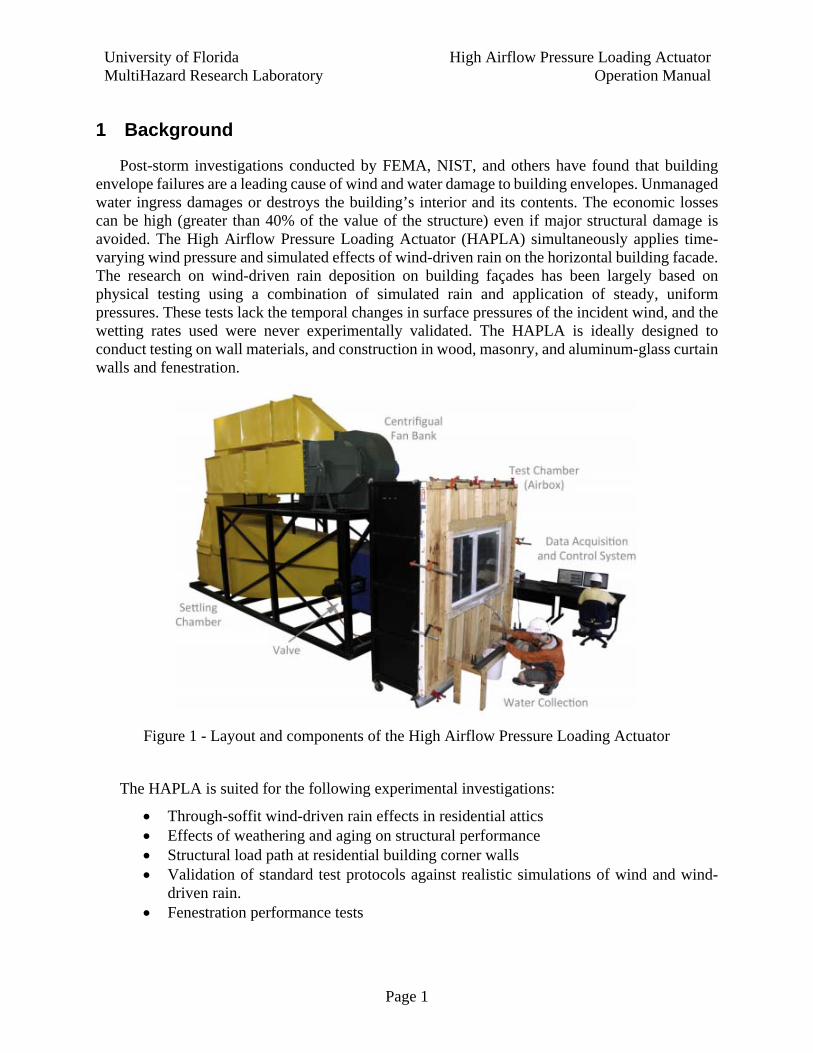
Post-storm investigations conducted by FEMA, NIST, and others have found that building envelope failures are a leading cause of wind and water damage to building envelopes. Unmanaged water ingress damages or destroys the building’s interior and its contents. The economic losses can be high (greater than 40% of the value of the structure) even if major structural damage is avoided. The High Airflow Pressure Loading Actuator (HAPLA) simultaneously applies time-varying wind pressure and simulated effects of wind-driven rain on the horizontal building facade. The research on wind-driven rain deposition on building façades has been largely based on physical testing using a combination of simulated rain and application of steady, uniform pressures. These tests lack the temporal changes in surface pressures of the incident wind, and the wetting rates used were never experimentally validated. The HAPLA is ideally designed to conduct testing on wall materials, and construction in wood, masonry, and aluminum-glass curtain walls and fenestration.
Figure 1 - Layout and components of the High Airflow Pressure Loading Actuator
The HAPLA is suited for the following experimental investigations:
Through-soffit wind-driven rain effects in residential attics Effects of weathering and aging on structural performance Structural load path at residential building corner walls Validation of standard test protocols against realistic simulations of wind and wind-
driven rain. Fenestration performance tests
University of Florida MultiHazard Research Laboratory
High Airflow Pressure Loading ActuatorOperation Manual
Page 2
1.1 Equipment Specifications and Capabilities The HAPLA consists of two 75 HP Centrifugal fans configured to operate in series. Using two
fans enables the HAPLA to maintain relatively high air through-flow (leakage) rates (up to 51 m3/min or 1,800 CFM).The ducting connects to a five-port air valve: that controls chamber pressure by modulating the amount of air traveling from the test chamber to the exhaust port. The valve disk is connected to a rotary actuation system that provides positioning feedback. This design enables the HAPLA to test components under simultaneous fluctuating pressure and wind-driven rain conditions, up to a 3 Hz waveform at pressures up to 6 kPa.
A variable intensity water spray system (VIWSS) was developed to simulate wind-driven rain effects on building envelope systems. The VIWSS is installed within steel chamber and it consists of two separate spray racks with 25 nozzles. The rack wetting uniformity across the chamber has been independently verified by Certified Testing Laboratories in Orlando, FL.
A National Instruments PXI system controls the pressure in the chamber through a 50 Hz Proportional-Integral-Derivative (PID) controller that receives feedback from a pressure transducer attached to the test chamber, which can follow rapidly varying pressures traces, with high fidelity.
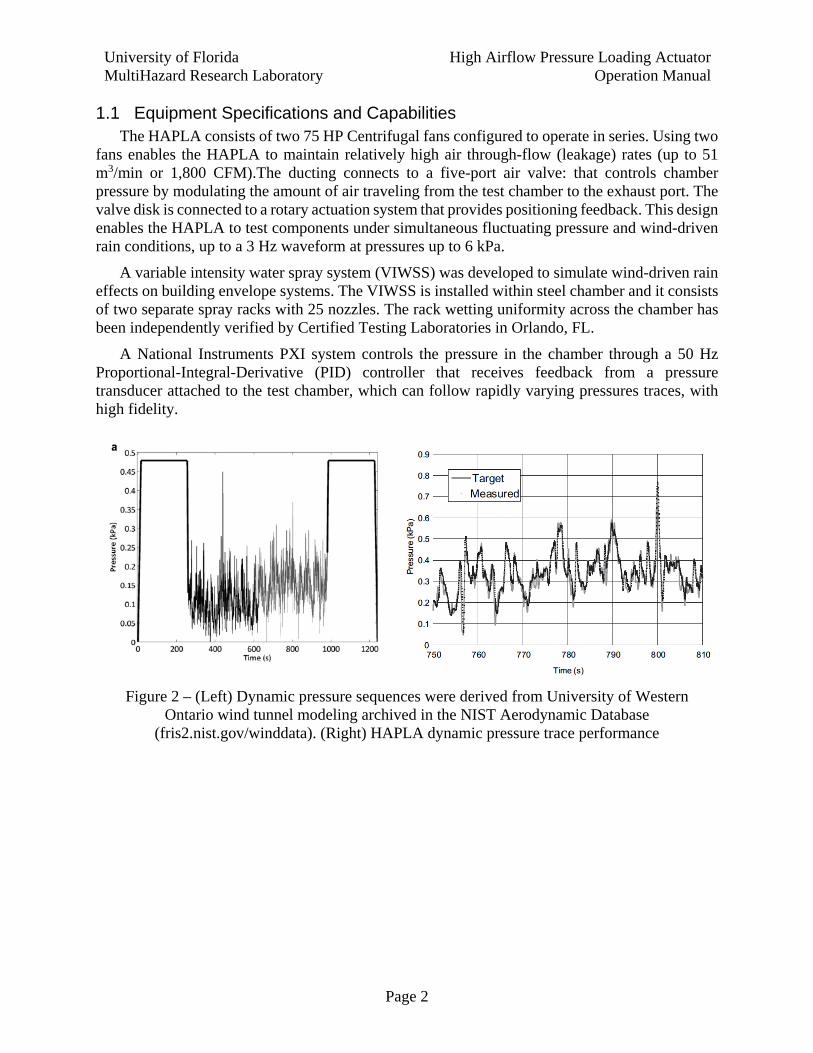
Figure 2 – (Left) Dynamic pressure sequences were derived from University of Western Ontario wind tunnel modeling archived in the NIST Aerodynamic Database
(fris2.nist.gov/winddata). (Right) HAPLA dynamic pressure trace performance
University of Florida MultiHazard Research Laboratory
High Airflow Pressure Loading ActuatorOperation Manual
Page 3
Details of the components are provided below:
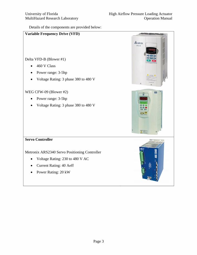
Variable Frequency Drive (VFD)
Delta VFD-B (Blower #1)
460 V Class
Power range: 3-5hp
Voltage Rating: 3 phase 380 to 480 V
WEG CFW-09 (Blower #2)
Power range: 3-5hp
Voltage Rating: 3 phase 380 to 480 V
Servo Controller
Metronix ARS2340 Servo Positioning Controller
Voltage Rating: 230 to 480 V AC
Current Rating: 40 Aeff
Power Rating: 20 kW
University of Florida MultiHazard Research Laboratory
High Airflow Pressure Loading ActuatorOperation Manual
Page 4
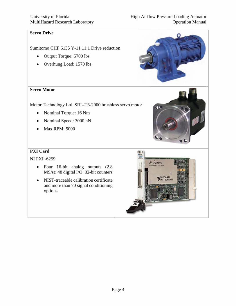
Servo Drive
Sumitomo CHF 6135 Y-11 11:1 Drive reduction
Output Torque: 5700 lbs
Overhung Load: 1570 lbs
Servo Motor
Motor Technology Ltd. SBL-T6-2900 brushless servo motor
Nominal Torque: 16 Nm
Nominal Speed: 3000 nN
Max RPM: 5000
PXI Card
NI PXI -6259
Four 16-bit analog outputs (2.8 MS/s); 48 digital I/O; 32-bit counters
NIST-traceable calibration certificate and more than 70 signal conditioning options
University of Florida MultiHazard Research Laboratory
High Airflow Pressure Loading ActuatorOperation Manual
Page 5
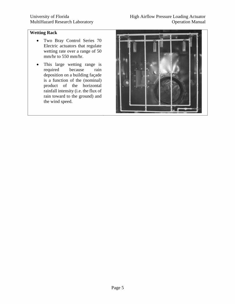
Wetting Rack
Two Bray Control Series 70 Electric actuators that regulate wetting rate over a range of 50 mm/hr to 550 mm/hr.
This large wetting range is required because rain deposition on a building façade is a function of the (nominal) product of the horizontal rainfall intensity (i.e. the flux of rain toward to the ground) and the wind speed.
University of Florida MultiHazard Research Laboratory
High Airflow Pressure Loading ActuatorOperation Manual
Page 6
2 Operation Instructions
The design of the HAPLA allows a wide variety of test setups and protocols. The size of the test chamber can be modified for any component size. Users will be able to choose from a library of pre-configured test types, such as air permeability or pressure. The facility is set up to evaluate durability issues by testing newly built wall systems against weathered building components. Users will then be able to choose from a library of test protocols, such as static, sinusoidal or realistic wind pressure trace for pressure tests, and acquire the test data for load and response via standard data acquisition interfaces. All test protocols and acquisition algorithms are customizable to ensure optimal experimental conditions. Control of the test protocol and data acquisition are handled within a common LabVIEW interface so that a common trigger can initiate both testing and data acquisition, ensuring time compatibility of the load and response data. All data will be archived to the CI and will be immediately available to the user for interpretation and analysis.
2.1 Powering On
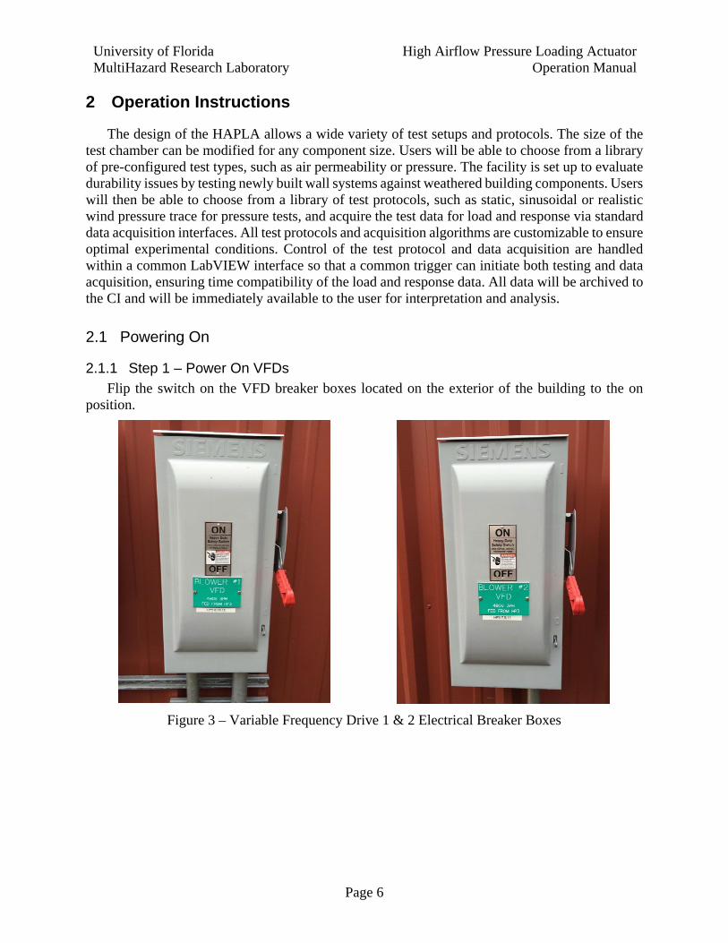
2.1.1 Step 1 – Power On VFDs Flip the switch on the VFD breaker boxes located on the exterior of the building to the on
position.
Figure 3 – Variable Frequency Drive 1 & 2 Electrical Breaker Boxes
University of Florida MultiHazard Research Laboratory
High Airflow Pressure Loading ActuatorOperation Manual
Page 7
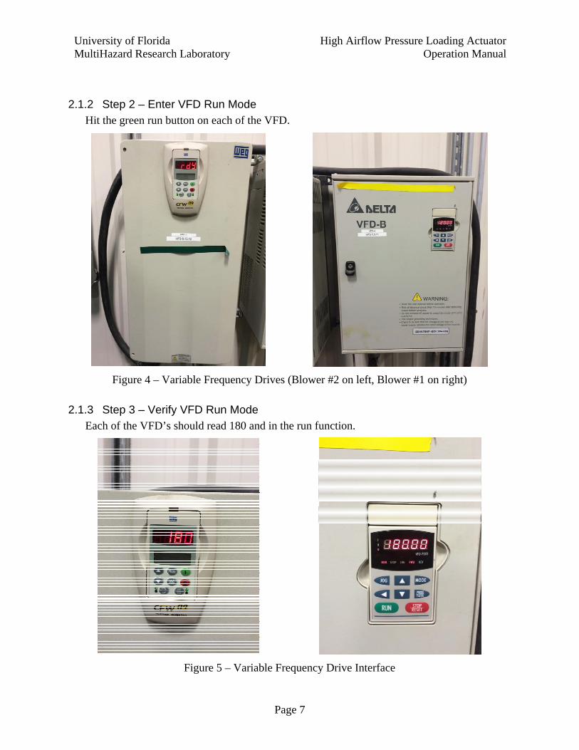
2.1.2 Step 2 – Enter VFD Run Mode Hit the green run button on each of the VFD.
Figure 4 – Variable Frequency Drives (Blower #2 on left, Blower #1 on right)
2.1.3 Step 3 – Verify VFD Run Mode Each of the VFD’s should read 180 and in the run function.
Figure 5 – Variable Frequency Drive Interface
University of Florida MultiHazard Research Laboratory
High Airflow Pressure Loading ActuatorOperation Manual
Page 8
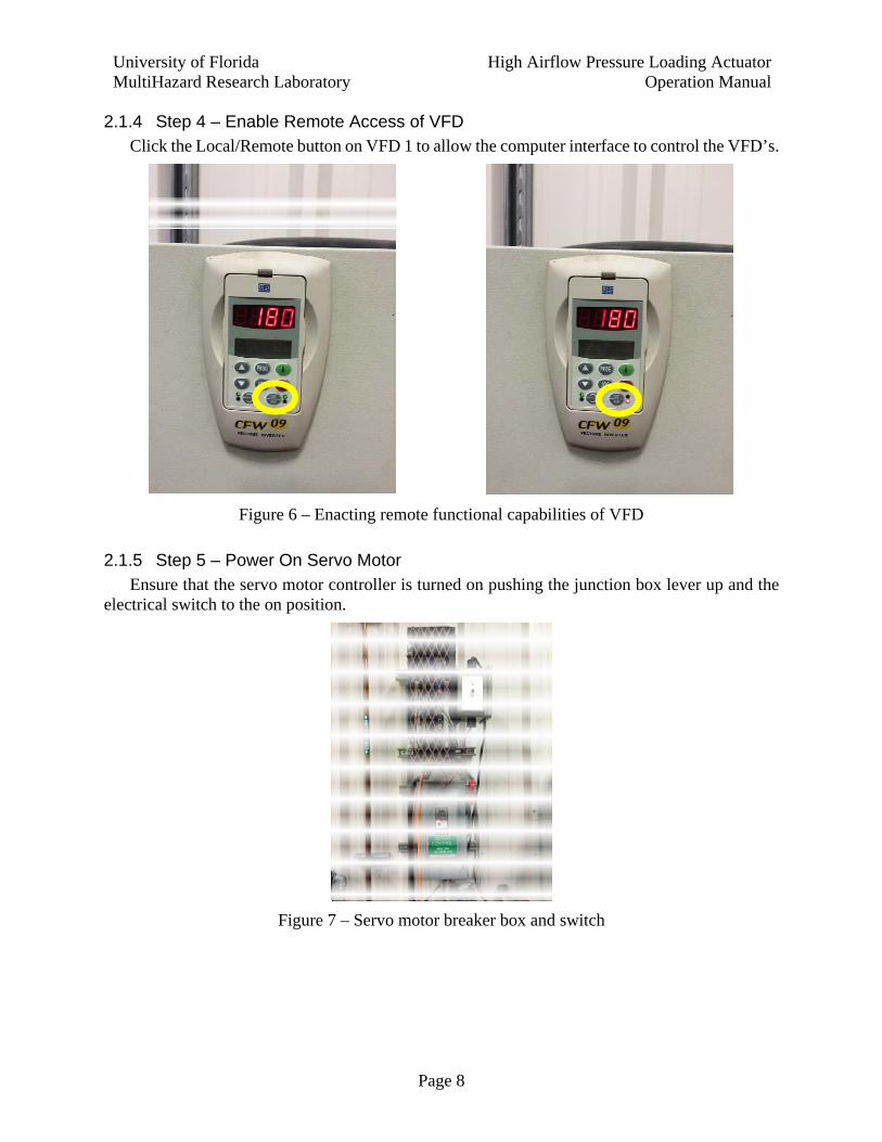
2.1.4 Step 4 – Enable Remote Access of VFD Click the Local/Remote button on VFD 1 to allow the computer interface to control the VFD’s.
Figure 6 – Enacting remote functional capabilities of VFD
2.1.5 Step 5 – Power On Servo Motor Ensure that the servo motor controller is turned on pushing the junction box lever up and the
electrical switch to the on position.
Figure 7 – Servo motor breaker box and switch
University of Florida MultiHazard Research Laboratory
High Airflow Pressure Loading ActuatorOperation Manual
Page 9
2.2 LabVIEW Interface
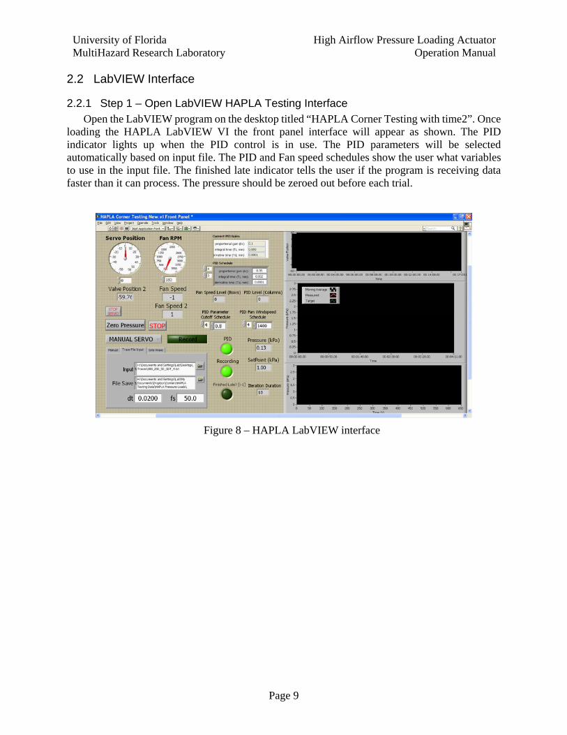
2.2.1 Step 1 – Open LabVIEW HAPLA Testing Interface Open the LabVIEW program on the desktop titled “HAPLA Corner Testing with time2”. Once
loading the HAPLA LabVIEW VI the front panel interface will appear as shown. The PID indicator lights up when the PID control is in use. The PID parameters will be selected automatically based on input file. The PID and Fan speed schedules show the user what variables to use in the input file. The finished late indicator tells the user if the program is receiving data faster than it can process. The pressure should be zeroed out before each trial.
Figure 8 – HAPLA LabVIEW interface
University of Florida MultiHazard Research Laboratory
High Airflow Pressure Loading ActuatorOperation Manual
Page 10
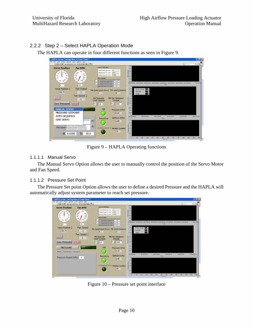
2.2.2 Step 2 – Select HAPLA Operation Mode The HAPLA can operate in four different functions as seen in Figure 9.
Figure 9 – HAPLA Operating functions
1.1.1.1 Manual Servo
The Manual Servo Option allows the user to manually control the position of the Servo Motor and Fan Speed.
1.1.1.2 Pressure Set Point
The Pressure Set point Option allows the user to define a desired Pressure and the HAPLA will automatically adjust system parameter to reach set pressure.
Figure 10 – Pressure set point interface
University of Florida MultiHazard Research Laboratory
High Airflow Pressure Loading ActuatorOperation Manual
Page 11
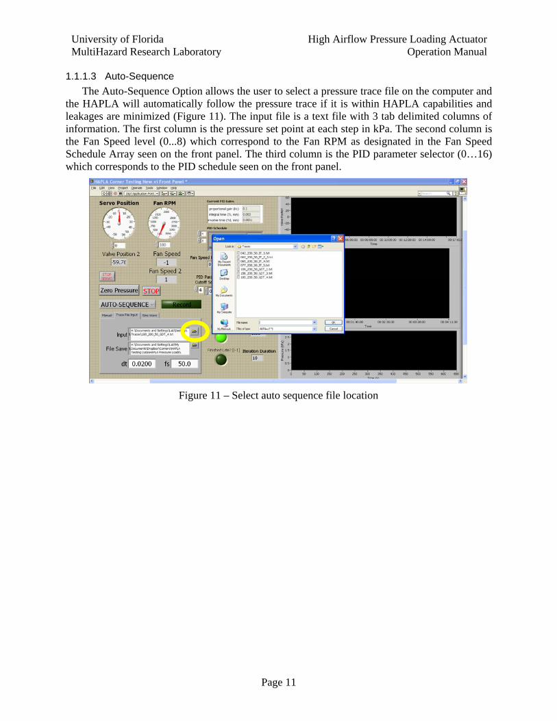
1.1.1.3 Auto-Sequence
The Auto-Sequence Option allows the user to select a pressure trace file on the computer and the HAPLA will automatically follow the pressure trace if it is within HAPLA capabilities and leakages are minimized (Figure 11). The input file is a text file with 3 tab delimited columns of information. The first column is the pressure set point at each step in kPa. The second column is the Fan Speed level (0...8) which correspond to the Fan RPM as designated in the Fan Speed Schedule Array seen on the front panel. The third column is the PID parameter selector (0…16) which corresponds to the PID schedule seen on the front panel.
Figure 11 – Select auto sequence file location

University of Florida MultiHazard Research Laboratory
High Airflow Pressure Loading ActuatorOperation Manual
Page 12
1.1.1.4 Sine Servo
The Sine Servo function initiates a sinusoidal servo motor position run.
Figure 12 – Sine Wave Function Interface
2.2.3 Step 3 – Select File Save Location Select the file save location. The pressure, time, and set point data is saved as a tab delimited
text file.
Figure 13 – File save location
University of Florida MultiHazard Research Laboratory
High Airflow Pressure Loading ActuatorOperation Manual
Page 13
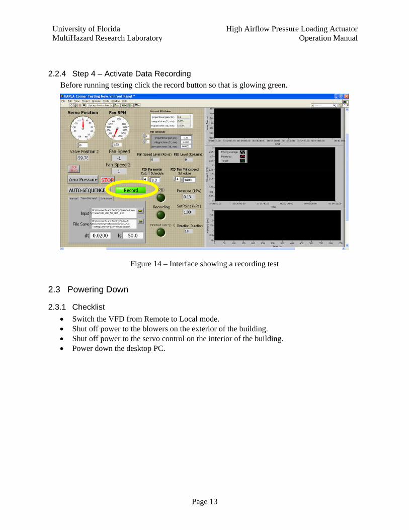
2.2.4 Step 4 – Activate Data Recording Before running testing click the record button so that is glowing green.
Figure 14 – Interface showing a recording test
2.3 Powering Down
2.3.1 Checklist
Switch the VFD from Remote to Local mode. Shut off power to the blowers on the exterior of the building. Shut off power to the servo control on the interior of the building. Power down the desktop PC.