airaccess - spirent · 2.5.1. initial software installation ... 4.2. file cabinet ... 4.3.1. base...
TRANSCRIPT
AirAccess CDMA Network Emulation
User Manual
Spirent 541 Industrial Way West Eatontown, NJ 07724 USA
Email: [email protected] Web: http://www.spirent.com
AMERICAS 1-800-SPIRENT • +1-818-676-2683 • [email protected] EUROPE AND THE MIDDLE EAST +44 (0) 1293 767979 • [email protected] ASIA AND THE PACIFIC +86-10-8518-2539 • [email protected]
This manual applies to AirAccess C2K, Version 4.40 and higher
Page Part Number: 71-005998, Version A12
Copyright © 2012 Spirent. All Rights Reserved.
Portions Copyright © 2005 QUALCOMM Inc. All rights reserved.
All of the company names and/or brand names and/or product names referred to in this document, in particular, the name “Spirent” and its logo device, are either registered trademarks or trademarks of Spirent plc and its subsidiaries, pending registration in accordance with relevant national laws. All other registered trademarks or trademarks are the property of their respective owners.
The information contained in this document is subject to change without notice and does not represent a commitment on the part of Spirent. The information in this document is believed to be accurate and reliable; however, Spirent assumes no responsibility or liability for any errors or inaccuracies that may appear in the document.
Safety Summary
If the equipment is used in a manner not specified by the manufacturer the protection provided by the equipment may be impaired.
Safety Symbols
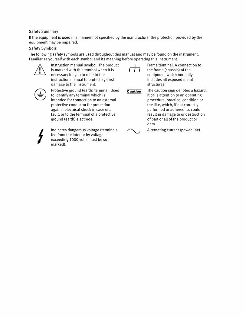
The following safety symbols are used throughout this manual and may be found on the instrument. Familiarize yourself with each symbol and its meaning before operating this instrument.
Instruction manual symbol. The product is marked with this symbol when it is necessary for you to refer to the instruction manual to protect against damage to the instrument.
Frame terminal. A connection to the frame (chassis) of the equipment which normally includes all exposed metal structures.
Protective ground (earth) terminal. Used to identify any terminal which is intended for connection to an external protective conductor for protection against electrical shock in case of a fault, or to the terminal of a protective ground (earth) electrode.
The caution sign denotes a hazard. It calls attention to an operating procedure, practice, condition or the like, which, if not correctly performed or adhered to, could result in damage to or destruction of part or all of the product or data.
Indicates dangerous voltage (terminals fed from the interior by voltage exceeding 1000 volts must be so marked).
Alternating current (power line).
Résumé des règles de sécurité
Si le matériel est utilisé d’une façon non conforme aux spécifications du constructeur, la protection assurée par le matériel peut être mise en défaut.
Symboles de sécurité
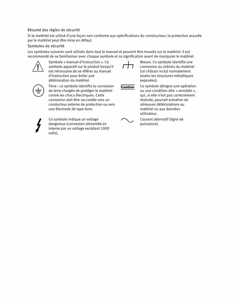
Les symboles suivants sont utilisés dans tout le manuel et peuvent être trouvés sur le matériel. Il est recommandé de se familiariser avec chaque symbole et sa signification avant de manipuler le matériel.
Symbole « manuel d’instruction ». Ce symbole apparaît sur le produit lorsqu’il est nécessaire de se référer au manuel d’instruction pour éviter une détérioration du matériel.
Masse. Ce symbole identifie une connexion au châssis du matériel (ce châssis inclut normalement toutes les structures métalliques exposées).
Terre : ce symbole identifie la connexion de terre chargée de protéger le matériel contre les chocs électriques. Cette connexion doit être raccordée vers un conducteur externe de protection ou vers une électrode de type terre.
Ce symbole désigne une opération ou une condition dite « sensible », qui, si elle n’est pas correctement réalisée, pourrait entraîner de sérieuses détériorations au matériel ou aux données utilisateur.
Ce symbole indique un voltage dangereux (connexion alimentée en interne par un voltage excédant 1000 volts).
Courant alternatif (ligne de puissance).
Table of Contents
1. Introduction .......................................................................................... 1
1.1. Overview ........................................................................................... 1
1.1.1. Product Highlights ................................................................................... 1
1.1.2. AirAccess Applications ............................................................................. 3
1.2. Theory of Operation ........................................................................... 3
1.2.1. Base Station to Mobile Station Network Model ......................................... 3
1.2.2. AirAccess Network Model ......................................................................... 4
2. System Setup ........................................................................................ 5
2.1. Overview ........................................................................................... 5
2.2. System Components .......................................................................... 5
2.2.1. AirAccess C2K Application Software ......................................................... 6
2.2.2. SR3452 V2 CDMA Network Emulator ......................................................... 8
2.2.3. SR3462 1xEV-DO Network Emulator .......................................................... 9
2.3. Installation ...................................................................................... 10
2.4. Logging onto the System Controller PC ............................................. 10
2.5. Software Setup ................................................................................ 11
2.5.1. Initial Software Installation ..................................................................... 11
2.5.2. Copy Protection ...................................................................................... 11
2.5.3. Application Software Updates ................................................................ 12
2.5.4. Configuring AirAccess for Data Testing .................................................... 13
2.6. Accessing the AirAccess User Manual ............................................... 14
3. Using AirAccess .................................................................................. 15
3.1. Overview ......................................................................................... 15
3.2. Powering on the Instruments ............................................................ 15
3.2.1. Powering-on AirAccess C2K with Multiple SR3452 V2s ............................. 15
3.3. Starting the Software ....................................................................... 16
3.4. Configuring the Test Instruments ...................................................... 16
3.4.1. RF Insertion Loss .................................................................................... 18
3.5. Loading a Pre-defined Configuration ................................................. 18
ii | AirAccess C2K User Manual
3.6. Connecting to the Instruments .......................................................... 19
3.7. Registering a Mobile Station ............................................................ 22
3.8. Placing a Phone Call ......................................................................... 23
4. Advanced Features .............................................................................. 25
4.1. Overview ......................................................................................... 25
4.2. File Cabinet...................................................................................... 25
4.2.1. Restoring a Test Configuration ............................................................... 26
4.2.2. Restoring a Test Session Log .................................................................. 26
4.3. Configuring Network Components .................................................... 26
4.3.1. Base Station Transceiver Subsystem (BTS) ............................................. 27
4.3.2. Base Station Controller (BSC) ................................................................. 32
4.3.3. 1xEV-DO Sector ...................................................................................... 37
4.3.4. 1xEV-DO Access Network (AN) ................................................................ 39
4.3.5. Core Network (CN) .................................................................................. 44
4.3.6. EHRPD Operation ................................................................................... 56
4.3.7. EV-DO RevB Operation ........................................................................... 56
4.3.8. Saving and Recalling Test Configurations ................................................57
4.3.9. Mobile Station (MS) ................................................................................57
4.4. Modifying Network Topology ............................................................ 59
4.4.1. Adding BTSs .......................................................................................... 59
4.4.2. Removing a BTS ..................................................................................... 59
4.4.3. Switching between BSC/AN Modes ........................................................ 59
4.5. Message Analyzer and Test Results .................................................. 61
4.5.1. Message Analyzer .................................................................................. 61
4.5.2. Clearing, Saving, and Recalling Logs ..................................................... 63
4.5.3. Message Filtering .................................................................................. 64
4.6. Authentication ................................................................................. 65
4.6.1. Setting the A-key ................................................................................... 65
4.6.2. Performing an SSD Update Procedure .................................................... 66
4.6.3. Enabling Authentication on Registration, Call Origination, and Call Termination ........................................................................................... 67
4.6.4. Performing the Unique Challenge-Response Procedure .......................... 68
4.6.5. AN Authentication in AirAccess............................................................... 69
4.7. Signaling Message Encryption and Voice Privacy .............................. 71
Table of Contents | iii
4.7.1. Enabling SME ........................................................................................ 72
4.7.2. Enabling VP ........................................................................................... 72
4.8. Service Negotiation .......................................................................... 73
4.8.1. Configuring Service Negotiation ............................................................ 73
4.8.2. Editing Service Configuration Attributes ................................................. 74
4.8.3. Strict Priority Order ................................................................................ 74
4.8.4. RLP BLOB ............................................................................................... 74
4.8.5. Viewing Service Negotiation Results ...................................................... 74
4.8.6. Service Renegotiation .............................................................................75
4.8.7. Configuring Selectable Mode Vocoder (SMV) ......................................... 76
4.9. Message Insertion ........................................................................... 77
4.9.1. Insert Messages on the Paging Channel .................................................. 77
4.9.2. Insert Messages on the Traffic Channel .................................................. 79
4.9.3. Position Location (IS-801.1) Message Insertion ...................................... 79
4.10. Fast Forward Power Control (FFPC) .................................................... 80
4.11. Customizing Call Processing ............................................................ 81
4.12. Mobile Station Equipment Identifier (MEID) ....................................... 82
4.12.1. Determination of MEID-capable Mobile Station ...................................... 82
4.12.2. Query of MEID from Mobile Station ........................................................ 82
4.12.3. Channel Assignment for MEID-capable Mobile Stations .......................... 83
4.12.4. Hard Handoff for MEID-capable Mobile Stations ..................................... 83
4.12.5. Over-the-Air Provisioning ...................................................................... 83
5. Handoffs ............................................................................................. 84
5.1. Overview ......................................................................................... 84
5.2. Configuring Handoff Tests ................................................................ 84
5.3. Configuring Neighbor Lists ............................................................... 84
5.4. Adjusting Sector Gains ..................................................................... 85
5.5. Idle Handoffs ................................................................................... 85
5.6. Soft Handoffs ................................................................................... 86
5.6.1. Reduced Active Set Soft Handoffs ........................................................... 89
5.7. Hard Handoffs ................................................................................. 89
5.8. Inter-technology Handoff .................................................................. 91
6. Data Services Testing .......................................................................... 93
6.1. Overview ......................................................................................... 93
iv | AirAccess C2K User Manual
6.2. Asynchronous Data Services ............................................................ 93
6.2.1. Establishing a Quick Net Connect Call .................................................... 93
6.2.2. Ending a Quick Net Connect Call ............................................................. 94
6.3. CDMA2000 1X and IS-95 Packet Data Services .................................. 94
6.3.1. Establishing a Packet Data Call .............................................................. 94
6.3.2. Ending a Packet Data Call ...................................................................... 95
6.3.3. Testing Active/Dormant State Transitions ............................................... 95
6.3.4. Using Supplemental Channels ............................................................... 96
6.3.5. RLP Statistics ......................................................................................... 97
6.3.6. RLP Frame Logging ................................................................................ 99
6.3.7. Exporting RLP Data Payloads .................................................................. 99
6.3.8. Selectable RLP3 Frame Types ............................................................... 100
6.3.9. Using the Test Data Service Option (TDSO) ........................................... 102
6.3.10. TDSO Counters .................................................................................... 103
6.4. 1xEV-DO Packet Data Services ........................................................ 104
6.5. Mobile IP Testing ........................................................................... 105
6.5.1. Enabling Mobile IP in AirAccess ............................................................ 105
6.5.2. Configuring Mobile IP Authentication in AirAccess ................................ 105
6.5.3. Placing a Mobile IP Call from the Mobile Station ................................... 105
6.5.4. Success Codes ...................................................................................... 107
6.5.5. Foreign Agent Error Codes .................................................................... 107
6.5.6. Home Agent Error Codes ...................................................................... 108
6.6. Dynamic Mobile IP Key Update (DMU) Testing ................................. 108
6.6.1. Configuring DMU Testing ..................................................................... 108
6.6.2. Configuring the Public/Private Key Pair ................................................ 109
6.6.3. Performing DMU Tests ......................................................................... 109
6.6.4. Customizing DMU Tests ........................................................................ 110
6.7. Maximum Data Rate Testing ........................................................... 110
6.8. Troubleshooting Data Service Tests ................................................ 112
6.8.1. MS-Terminated Data Call Failed ............................................................ 112
6.8.2. Mobile is Busy with Another Call ........................................................... 112
7. Overlay Services Testing ................................................................... 113
7.1. Overview ....................................................................................... 113
7.2. Short Message Service (SMS) ......................................................... 113
Table of Contents | v
7.2.1. Mobile Terminated SMS ........................................................................ 114
7.2.2. Mobile Originated SMS ......................................................................... 114
7.2.3. Broadcast SMS ..................................................................................... 115
7.2.4. Saving and Recalling SMS Messages .................................................... 115
7.3. Multimedia Messaging Service (MMS) ............................................ 116
7.4. OTA Service Provisioning and Parameter Administration .................. 116
7.4.1. OTASP Testing ...................................................................................... 116
7.4.2. OTAPA Testing ...................................................................................... 118
7.4.3. PRL Operations with OTASP/OTAPA ....................................................... 119
8. Using TAP Protocols .......................................................................... 121
8.1. Overview ....................................................................................... 121
9. Maintenance ..................................................................................... 122
10. Technical Specifications ................................................................... 125
10.1. Overview ....................................................................................... 125
10.2. RF Generator .................................................................................. 125
10.3. RF Receiver .................................................................................... 127
10.4. Timebase Specifications ................................................................ 128
10.5. Trigger/Clock/Sync Interfaces ........................................................ 129
10.6. General Specifications ................................................................... 130
11. Appendix: Reference ......................................................................... 131
11.1. SR3452 V2 Clocks and Triggers ...................................................... 131
1. Introduction
1.1. Overview
AirAccess CDMA Network Emulation is a scalable performance analysis solution for CDMA 1X, 1xEV-DO, and eHRPD terminal manufacturers and service providers. AirAccess combines powerful application software with a high-speed protocol processing engine to provide complete emulation of a multi-cell CDMA networks.
1.1.1. Product Highlights
The Network Emulator provides maximum coverage of Minimum Performance and Signaling Conformance specifications.
AirAccess provides dynamic emulation not found in one-box radio test sets or program-driven conformance test systems currently available. This network emulation is essential to support a broad range of applications, including TIA/EIA-98 Minimum Performance Standards for CDMA2000, TIA/EIA-898 and TIA/EIA-1043 Signaling Conformance Tests for CDMA2000, TIA-866A Minimum Performance Standards for 1xEV-DO, TIA-919B Signaling Conformance Tests for 1xEV-DO, and C.S0095 E-UTRAN CDMA 2000 Connectivity tests for eHRPD.
Simultaneous CDMA2000 1X and 1xEV-DO/eHRPD network emulation.
AirAccess 1xPLUS simultaneously provides both CDMA2000 1X (including IS-95A/B and J-STD-008) and 1xEV-DO (including Rev0, RevA, RevB and eHRPD) network emulation. These emulated networks share common CDMA system time that enables testing of hybrid access terminals and dormant data handoffs between networks.
Real-time network emulation.
AirAccess implements powerful real-time state machines, similar to those found in commercial CDMA2000 1X and 1xEV-DO/eHRPD network infrastructures. This ensures base station and access network performance, as well as timing similar to the performance when testing on real 1X and 1xEV-DO/eHRPD networks.
Powerful user interface for easy test scenarios creation, without test script generation or software programming.
An interactive, user interface allows configuration of network components, including CDMA 2000 1X BTSs and BSC components and EV-DO Rev0/RevA/RevB/eHRPD AN and Sectors. This allows a user interface-driven custom configuration of overhead messages, setting of sector powers, and asynchronous event triggering.
2 | AirAccess C2K User Manual
Multi-sector, multi-BSC emulation, up to two independent carrier frequencies for true soft, softer, hard handoffs, and pilot pollution testing.
AirAccess provides multiple independent BSCs/ANs (1 or 2) and up to six (6) 1X BTS sectors and up to two (2) EV-DO sectors. Each BSC/AN is capable of transmitting on a different CDMA carrier, making true multi-frequency testing possible (handoffs across frequencies or bands, redirection to different frequencies or bands). Multiple sectors allow the creation of almost any handoff scenario, as well as pilot pollution simulation.
Supports overlay services such as SMS, OTA, data and E911.
Essential to the successful launch of a commercial mobile is its ability to perform overlay services. These features are above and beyond the basic air interface (call processing) defined in IS-95 or IS-2000. While call processing is essential, it is the overlay services that are marketable to a consumer.
Instrument API for automated TIA/EIA-98, TIA/EIA-898 (CDG Stage 2) and Location-Based Services test solution integration.
The C2K Automatic Test System (C2K-ATS) provides an integrated test solution for evaluating performance of CDMA mobile devices. AirAccess is an integral part of C2K-ATS, providing the advanced network emulation required for TIA/EIA-98, TIA/EIA-898 (CDG Stage 2) and Location-Based Services testing. The TASKIT/C2K Test Executive software automates mobile testing by controlling AirAccess through an Instrument API, stepping through the test sequences, and logging the results. This same Instrument API is available to generate custom automated test cases.
Supports all CDMA band classes.
The SR3452 V2 contains flexible RF converters that provide frequency coverage from 400 to 2700 MHz. This allows testing within all band classes defined by IMT-2000. When the SR3452 V2 with Internal RF is used, the AirAccess system supports Band Classes 0 (North American Cellular), 1 (North American PCS), 3 (JTACS), 4 (Korean PCS), 5 (NMT), 6 (IMT), 10 (Secondary 800 MHz), 14 (US PCS 1.9 GHz), and 15 (AWS).
Provides Mobile IP emulation and test capability.
Included in AirAccess is the emulation of network entities, such as a PSDN (packet Data Serving Node), Home Agent, Foreign Agents, and an AAA server for 1X/EV-DO packet data calls and PDN-GW, HSGW, 3GPP AAA Server for eHRPD packet data calls. The availability and configurability of these components provides the ability to test the packet data capabilities of the mobile terminal in a Mobile IP network or Proxy Mobile IP network for eHRPD. Over-the-air exchange of MN-HA and MN-AAA authentication keys is also supported with built-in Dynamic Mobile IP Key Update (DMU) functionality.
Chapter One: Introduction | 3
1.1.2. AirAccess Applications
AirAccess provides thorough testing of 2G and 3G CDMA mobile devices and 1xEV-DO access terminals in a laboratory setting. It gives accurate and repeatable test results, allowing performance problems to be detected, isolated, and corrected in the shortest possible time. AirAccess eliminates the need for expensive infrastructure equipment and can drastically reduce the time spent doing field tests where conditions cannot be controlled or repeated.
Applications for AirAccess include:
• Product Development
• Design Verification
• Product Qualification
• Conformance Test
• Competitive Analysis
• Performance Analysis
1.2. Theory of Operation
1.2.1. Base Station to Mobile Station Network Model
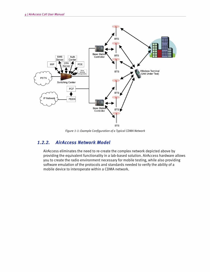
A mobile station is required to operate in a CDMA network; a very complex structure consisting of many components. This includes multiple base stations, multiple base station controllers, a mobile switching center, and servers for applications, such as authentication, SMS, OTA, and data.
A sample CDMA network is shown in Figure 1-1.
4 | AirAccess C2K User Manual
Figure 1-1: Example Configuration of a Typical CDMA Network
1.2.2. AirAccess Network Model
AirAccess eliminates the need to re-create the complex network depicted above by providing the equivalent functionality in a lab-based solution. AirAccess hardware allows you to create the radio environment necessary for mobile testing, while also providing software emulation of the protocols and standards needed to verify the ability of a mobile device to interoperate within a CDMA network.
2. System Setup
2.1. Overview
AirAccess CDMA Network Emulation provides an integrated test solution for evaluating second and third generation CDMA mobile units and/or 1xEV-DO access terminals. By combining network emulation available via advanced software with a physical interface provided via scalable hardware, AirAccess provides a highly configurable and powerful system for emulation of an entire CDMA network air interface.
The following chapter explains the steps required to configure your AirAccess system:
• Guided Tour of System Components Section 2.2 on page 5
• Connecting the Instruments Section 2.3 on page 10
• Logging onto the System Controller PC Section 2.4 on page 10
• Software Installation and Updates Section 2.5 on page 11
• Accessing the User Manual Section 2.6 on page 14
Refer to Chapter Three on page 15 for details on starting your AirAccess system and running the software for the first time.
2.2. System Components
AirAccess systems combine powerful instruments and software into a complete, integrated test system. The instruments and software that comprise an AirAccess system vary based on the AirAccess configuration.
The major components of an AirAccess C2K system with two channel (CDMA Only) RF conversion include:
• AirAccess C2K Application Software
• Two SR3452 V2 CDMA Network Emulators
• SR3610 Packet Core Network Emulator
The major components of an AirAccess C2K system with one channel (CDMA Only) RF conversion include:
• AirAccess C2K Application Software
• One SR3452 V2 CDMA Network Emulator
• SR3610 Packet Core Network Emulator
6 | AirAccess C2K User Manual
The major components of an AirAccess 1xPLUS (CDMA and EV-DO) system include:
• AirAccess C2K Application Software
• Two SR3452 V2 CDMA Network Emulators
• An SR3462 1xEV Rev0/RevA Network Emulator
• SR3610 Packet Core Network Emulator
NOTE: AirAccess 1xPLUS system can be upgraded to a three channel RF conversion system to support EV-DO RevB with two EV-DO RevB carriers and one 1xRTT carrier.
The major components of an AirAccess 1x/EV-DO system with one (CDMA or EV-DO) RF conversion include:
• AirAccess C2K Application Software
• One SR3452 V2 CDMA Network Emulator
• An SR3462 1xEV Rev0/RevA Network Emulator with embedded Packet Core Network Emulator
The first three configurations of AirAccess are also used within Spirent automated test systems, including C2K-ATS (with or without EV-DO), PLTS, C2K Data, C2K SC (Signaling Conformance), and C2K PoC (Push-to-talk over Cellular).
Each of the above components is described in the following sections.
2.2.1. AirAccess C2K Application Software
This section is applicable to AirAccess C2K and AirAccess 1xPLUS.
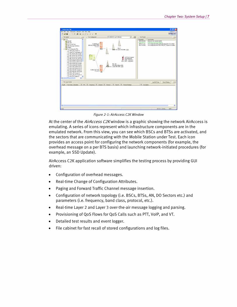
The AirAccess C2K software is a Windows-based application that provides the ability to configure and control a wide range of emulated wireless network infrastructure components within an easy-to-use GUI. AirAccess complements this flexibility with a real-time Message Analyzer, Test Results Log, and File Cabinet for fast retrieval of stored configuration files and test logs. The AirAccess C2K window is shown in Figure 2-1.
Chapter Two: System Setup | 7
Figure 2-1: AirAccess C2K Window
At the center of the AirAccess C2K window is a graphic showing the network AirAccess is emulating. A series of icons represent which infrastructure components are in the emulated network. From this view, you can see which BSCs and BTSs are activated, and the sectors that are communicating with the Mobile Station under Test. Each icon provides an access point for configuring the network components (for example, the overhead message on a per BTS basis) and launching network-initiated procedures (for example, an SSD Update).
AirAccess C2K application software simplifies the testing process by providing GUI driven:
• Configuration of overhead messages.
• Real-time Change of Configuration Attributes.
• Paging and Forward Traffic Channel message insertion.
• Configuration of network topology (i.e. BSCs, BTSs, AN, DO Sectors etc.) and parameters (i.e. frequency, band class, protocol, etc.).
• Real-time Layer 2 and Layer 3 over-the-air message logging and parsing.
• Provisioning of QoS Flows for QoS Calls such as PTT, VoIP, and VT.
• Detailed test results and event logger.
• File cabinet for fast recall of stored configurations and log files.
8 | AirAccess C2K User Manual
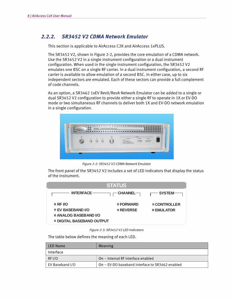
2.2.2. SR3452 V2 CDMA Network Emulator
This section is applicable to AirAccess C2K and AirAccess 1xPLUS.
The SR3452 V2, shown in Figure 2-2, provides the core emulation of a CDMA network. Use the SR3452 V2 in a single instrument configuration or a dual instrument configuration. When used in the single instrument configuration, the SR3452 V2 emulates one BSC on a single RF carrier. In a dual instrument configuration, a second RF carrier is available to allow emulation of a second BSC. In either case, up to six independent sectors are emulated. Each of these sectors can provide a full complement of code channels.
As an option, a SR3462 1xEV Rev0/RevA Network Emulator can be added to a single or dual SR3452 V2 configuration to provide either a single RF to operate in 1X or EV-DO mode or two simultaneous RF channels to deliver both 1X and EV-DO network emulation in a single configuration.
Figure 2-2: SR3452 V2 CDMA Network Emulator
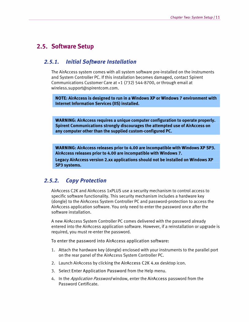
The front panel of the SR3452 V2 includes a set of LED indicators that display the status of the instrument.
STATUS INTERFACE
RF I/O EV BASEBAND I/O ANALOG BASEBAND I/O DIGITAL BASEBAND OUTPUT
CHANNEL
FORWARD REVERSE
SYSTEM
CONTROLLER EMULATOR
Figure 2-3: SR3452 V2 LED Indicators
The table below defines the meaning of each LED.
LED Name Meaning
Interface
RF I/O On – Internal RF interface enabled
EV Baseband I/O On – EV-DO baseband interface to SR3462 enabled

Chapter Two: System Setup | 9
LED Name Meaning
Analog Baseband I/O On – Analog baseband interface enabled
Digital Baseband Output On – Digital baseband output interface enabled
Channel
Forward On – At least one code channel being transmitted from the SR3452 V2
Reverse On – Energy detected on the reverse link
System
Controller On – Communicating with AirAccess application
Emulator Flashing Green – SR3452 V2 initializing Green – SR3452 V2initialized successfully and passed built-in self-test Flashing Red – Failed to download instrument firmware from the PC Red – Failed built-in self-test
2.2.3. SR3462 1xEV-DO Network Emulator
The SR3462 1xEV-DO Network Emulator provides the core emulation of a 1xEV-DO Rev. 0/RevA/RevB and eHRPD networks.
Figure 2-4: SR3462 1xEV Network Emulator
A single SR3462 provides emulation of multiple 1xEV-DO sectors. The SR3462 interfaces with the access terminal under test through the RF converters embedded with SR3452 V2 CDMA Network Emulator. The SR3462 connects to the primary SR3452 V2 through a high-density digital connection.
The front panel of the SR3462 includes two LED indicators to provide a quick reference to the status of the equipment. The Emulator LED indicates the state of the SR3462. It flashes while the emulator is initializing. If it is green, the emulator is ready for use. If it is red, the emulator failed to initialize correctly.
The Controller LED illuminates when the emulator is communicating with the AirAccess C2K software running on the system controller PC.

10 | AirAccess C2K User Manual
The rear panel of the SR3462 provides I/O connections, including Ethernet and 1xEV-DO digital baseband signals.
2.3. Installation
Refer to the Setup Guide for your test system for instructions on cabling your AirAccess instruments.
2.4. Logging onto the System Controller PC
The AirAccess System Controller PC is shipped-configured with an account for administrative privileges. This is the default account used for executing AirAccess applications.
To log on to the System Controller PC using the default account:
1. Power on the System Controller PC and monitor.
2. Wait for the Windows Log-on prompt to display. You may be required to press CTRL-ALT-DEL after Windows completes booting.
3. When the Windows logon is presented, use the following logon: Username: Spirent Password: Sp!rent
NOTE: For systems shipped prior to September 2003, the initial Administrator password was blank.
NOTE: When logged onto Windows with this administrative account, it is possible to create additional user accounts. These user accounts are used for regular execution of AirAccess applications. However, when installing new or updated AirAccess software, it is necessary to log back onto Windows with administrative privileges to perform the installation.
NOTE: If the System Controller PC is connected to your company network via the ”FastEthernet 0/0” port on the Router, the use of the Administrator logon might cause a conflict. Consult your network administrator to establish an appropriate account on the System Controller PC.
Chapter Two: System Setup | 11
2.5. Software Setup
2.5.1. Initial Software Installation
The AirAccess system comes with all system software pre-installed on the instruments and System Controller PC. If this installation becomes damaged, contact Spirent Communications Customer Care at +1 (732) 544-8700, or through email at [email protected].
NOTE: AirAccess is designed to run in a Windows XP or Windows 7 environment with Internet Information Services (IIS) installed.
WARNING: AirAccess requires a unique computer configuration to operate properly. Spirent Communications strongly discourages the attempted use of AirAccess on any computer other than the supplied custom-configured PC.
WARNING: AirAccess releases prior to 4.00 are incompatible with Windows XP SP3. AirAccess releases prior to 4.00 are incompatible with Windows 7.
Legacy AirAccess version 2.xx applications should not be installed on Windows XP SP3 systems.
2.5.2. Copy Protection
AirAccess C2K and AirAccess 1xPLUS use a security mechanism to control access to specific software functionality. This security mechanism includes a hardware key (dongle) to the AirAccess System Controller PC and password-protection to access the AirAccess application software. You only need to enter the password once after the software installation.
A new AirAccess System Controller PC comes delivered with the password already entered into the AirAccess application software. However, if a reinstallation or upgrade is required, you must re-enter the password.
To enter the password into AirAccess application software:
1. Attach the hardware key (dongle) enclosed with your instruments to the parallel port on the rear panel of the AirAccess System Controller PC.
2. Launch AirAccess by clicking the AirAccess C2K 4.xx desktop icon.
3. Select Enter Application Password from the Help menu.
4. In the Application Password window, enter the AirAccess password from the Password Certificate.
12 | AirAccess C2K User Manual
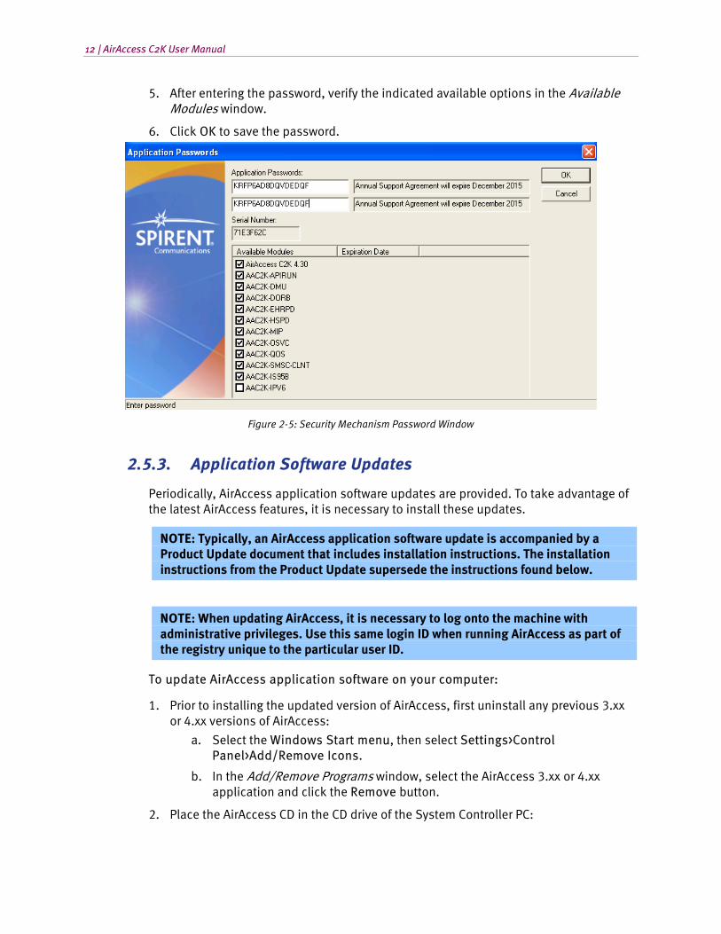
5. After entering the password, verify the indicated available options in the Available Modules window.
6. Click OK to save the password.
Figure 2-5: Security Mechanism Password Window
2.5.3. Application Software Updates
Periodically, AirAccess application software updates are provided. To take advantage of the latest AirAccess features, it is necessary to install these updates.
NOTE: Typically, an AirAccess application software update is accompanied by a Product Update document that includes installation instructions. The installation instructions from the Product Update supersede the instructions found below.
NOTE: When updating AirAccess, it is necessary to log onto the machine with administrative privileges. Use this same login ID when running AirAccess as part of the registry unique to the particular user ID.
To update AirAccess application software on your computer:
1. Prior to installing the updated version of AirAccess, first uninstall any previous 3.xx or 4.xx versions of AirAccess:
a. Select the Windows Start menu, then select Settings>Control Panel>Add/Remove Icons.
b. In the Add/Remove Programs window, select the AirAccess 3.xx or 4.xx application and click the Remove button.
2. Place the AirAccess CD in the CD drive of the System Controller PC:
Chapter Two: System Setup | 13
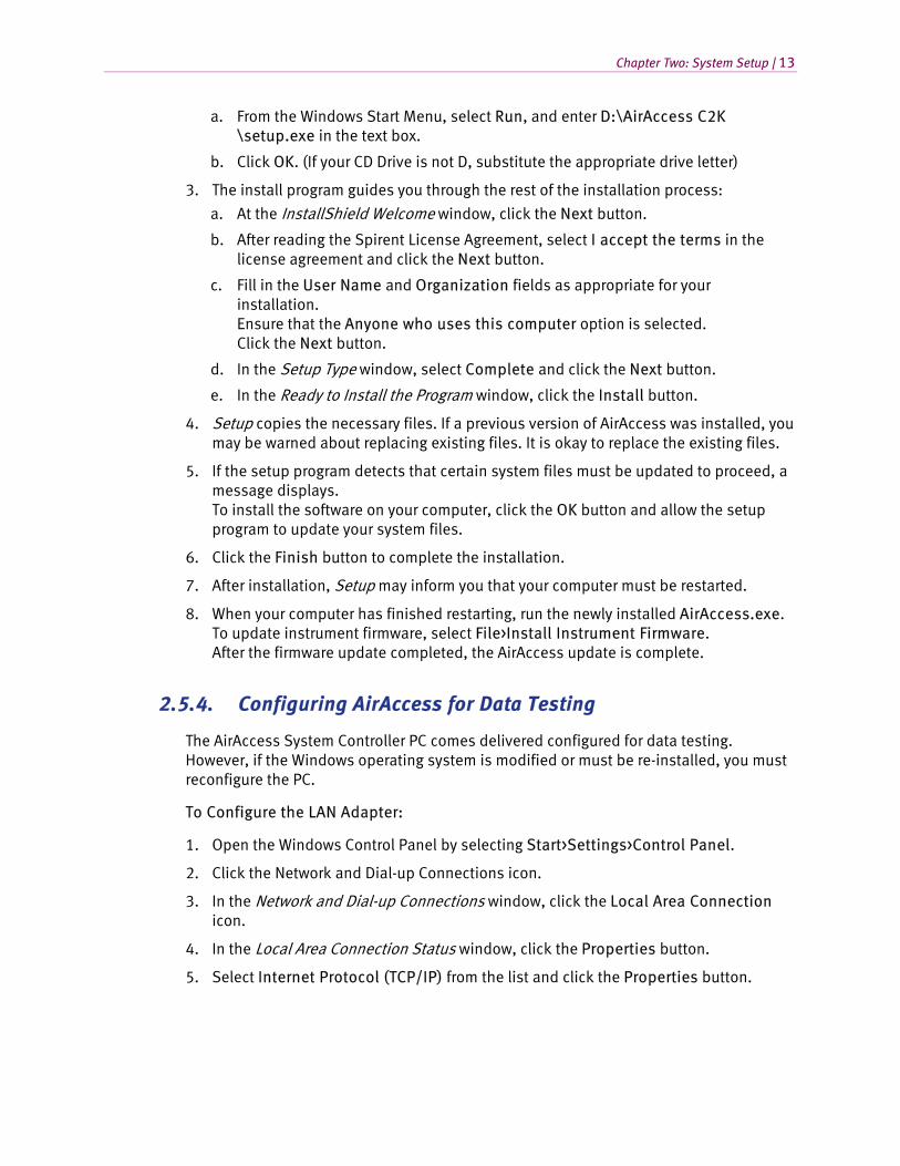
a. From the Windows Start Menu, select Run, and enter D:\AirAccess C2K \setup.exe in the text box.
b. Click OK. (If your CD Drive is not D, substitute the appropriate drive letter)
3. The install program guides you through the rest of the installation process:
a. At the InstallShield Welcome window, click the Next button.
b. After reading the Spirent License Agreement, select I accept the terms in the license agreement and click the Next button.
c. Fill in the User Name and Organization fields as appropriate for your installation. Ensure that the Anyone who uses this computer option is selected. Click the Next button.
d. In the Setup Type window, select Complete and click the Next button.
e. In the Ready to Install the Program window, click the Install button.
4. Setup copies the necessary files. If a previous version of AirAccess was installed, you may be warned about replacing existing files. It is okay to replace the existing files.
5. If the setup program detects that certain system files must be updated to proceed, a message displays. To install the software on your computer, click the OK button and allow the setup program to update your system files.
6. Click the Finish button to complete the installation.
7. After installation, Setup may inform you that your computer must be restarted.
8. When your computer has finished restarting, run the newly installed AirAccess.exe. To update instrument firmware, select File>Install Instrument Firmware. After the firmware update completed, the AirAccess update is complete.
2.5.4. Configuring AirAccess for Data Testing
The AirAccess System Controller PC comes delivered configured for data testing. However, if the Windows operating system is modified or must be re-installed, you must reconfigure the PC.
To Configure the LAN Adapter:
1. Open the Windows Control Panel by selecting Start>Settings>Control Panel.
2. Click the Network and Dial-up Connections icon.
3. In the Network and Dial-up Connections window, click the Local Area Connection icon.
4. In the Local Area Connection Status window, click the Properties button.
5. Select Internet Protocol (TCP/IP) from the list and click the Properties button.
14 | AirAccess C2K User Manual
6. Select Use the following IP address and enter the following values: IP address: 192.168.0.5 Subnet mask: 255.255.255.0 Default gateway: 192.168.0.1
7. Select Use the following DNS server addresses and enter a DNS server available on your company network in the Preferred DNS Server field.
8. Click OK to exit the Internet Protocol (TCP/IP) Properties window.
9. Click OK to exit the Local Area Connection Properties window.
10. Click Close to exit the Local Area Connection Status window.
11. Close the Network and Dial-up Connections window.
2.6. Accessing the AirAccess User Manual
This manual is available on the CD-ROM included with the AirAccess system. Use Windows Explorer to view the D:\Manuals folder (replace “D:” with the appropriate letter if your CD drive is not D). This folder contains a file called AIRACCESS MANUAL.PDF. A copy of this file is automatically copied to your hard drive during software installation. A Windows desktop icon is included for convenient access. You can view and print this file using Adobe Acrobat Reader. If Adobe Acrobat Reader is not already installed on your System Controller PC, an installation executable is included in the Manuals directory on the AirAccess CD.

3. Using AirAccess
3.1. Overview
The following chapter provides the instructions necessary to start the AirAccess software and establish basic communications with the Mobile Station under Test.
This chapter contains the following sections:
• Powering on the Instruments Section 3.2 on page 15
• Starting the Software Section 3.3 on page 16
• Configuring the Test Instruments Section 3.4 on page 16
• Loading a Pre-defined Configuration Section 3.5 on page 18
• Connecting to the Instruments Section 3.6 on page 19
• Registering a Mobile Station Section 3.7 on page 22
• Placing a Phone Call Section 3.8 on page 23
3.2. Powering on the Instruments
Prior to powering on the AirAccess instruments, ensure the hardware instruments are interconnected as specified in Chapter 2 of this manual.
NOTE: Timing within the AirAccess system is critical for successful operation. It is necessary to follow the startup procedure documented below each time the system is powered on to ensure proper initialization.
3.2.1. Powering-on AirAccess C2K with Multiple SR3452 V2s
After the instruments are connected, perform the following steps:
1. If equipped, power on the router. Wait three minutes to allow the router to boot.
2. Power on the System Controller PC and Monitor.
3. Power on the primary SR3452 V2 and wait for the Emulator LED to turn solid green (approximately 30 seconds).
4. If equipped, power on the secondary SR3452 V2 and wait for the Emulator LED to turn solid green (approximately 30 seconds).
5. If equipped, power on the tertiary SR3452 V2 and wait for the Emulator LED to turn solid green (approximately 30 seconds)
6. If equipped, power on the SR3462.
16 | AirAccess C2K User Manual
3.3. Starting the Software
Prior to starting the AirAccess software, ensure that the instruments are powered on as specified in Section 3.1 of this Manual.
Launch the AirAccess C2K software by clicking the AirAccess C2K 4.40 shortcut on the desktop.
3.4. Configuring the Test Instruments
The AirAccess test instruments can be used in several different configurations. After starting the AirAccess application, it is sometimes necessary to select the instrument configuration used before beginning testing.
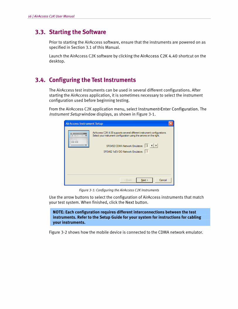
From the AirAccess C2K application menu, select Instrument>Enter Configuration. The Instrument Setup window displays, as shown in Figure 3-1.
Figure 3-1: Configuring the AirAccess C2K Instruments
Use the arrow buttons to select the configuration of AirAccess instruments that match your test system. When finished, click the Next button.
NOTE: Each configuration requires different interconnections between the test instruments. Refer to the Setup Guide for your system for instructions for cabling your instruments.
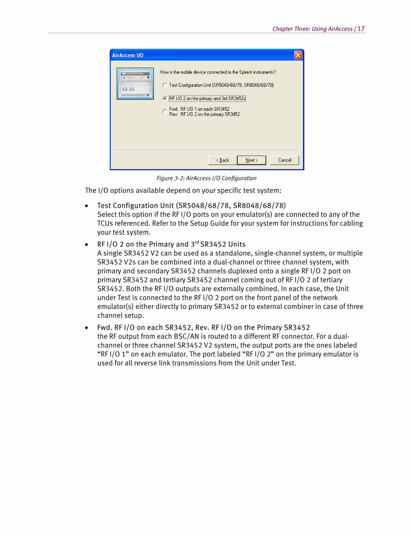
Figure 3-2 shows how the mobile device is connected to the CDMA network emulator.
Chapter Three: Using AirAccess | 17
Figure 3-2: AirAccess I/O Configuration
The I/O options available depend on your specific test system:
• Test Configuration Unit (SR5048/68/78, SR8048/68/78) Select this option if the RF I/O ports on your emulator(s) are connected to any of the TCUs referenced. Refer to the Setup Guide for your system for instructions for cabling your test system.
• RF I/O 2 on the Primary and 3rd SR3452 Units A single SR3452 V2 can be used as a standalone, single-channel system, or multiple SR3452 V2s can be combined into a dual-channel or three channel system, with primary and secondary SR3452 channels duplexed onto a single RF I/O 2 port on primary SR3452 and tertiary SR3452 channel coming out of RF I/O 2 of tertiary SR3452. Both the RF I/O outputs are externally combined. In each case, the Unit under Test is connected to the RF I/O 2 port on the front panel of the network emulator(s) either directly to primary SR3452 or to external combiner in case of three channel setup.
• Fwd. RF I/O on each SR3452, Rev. RF I/O on the Primary SR3452 the RF output from each BSC/AN is routed to a different RF connector. For a dual-channel or three channel SR3452 V2 system, the output ports are the ones labeled “RF I/O 1” on each emulator. The port labeled “RF I/O 2” on the primary emulator is used for all reverse link transmissions from the Unit under Test.
18 | AirAccess C2K User Manual
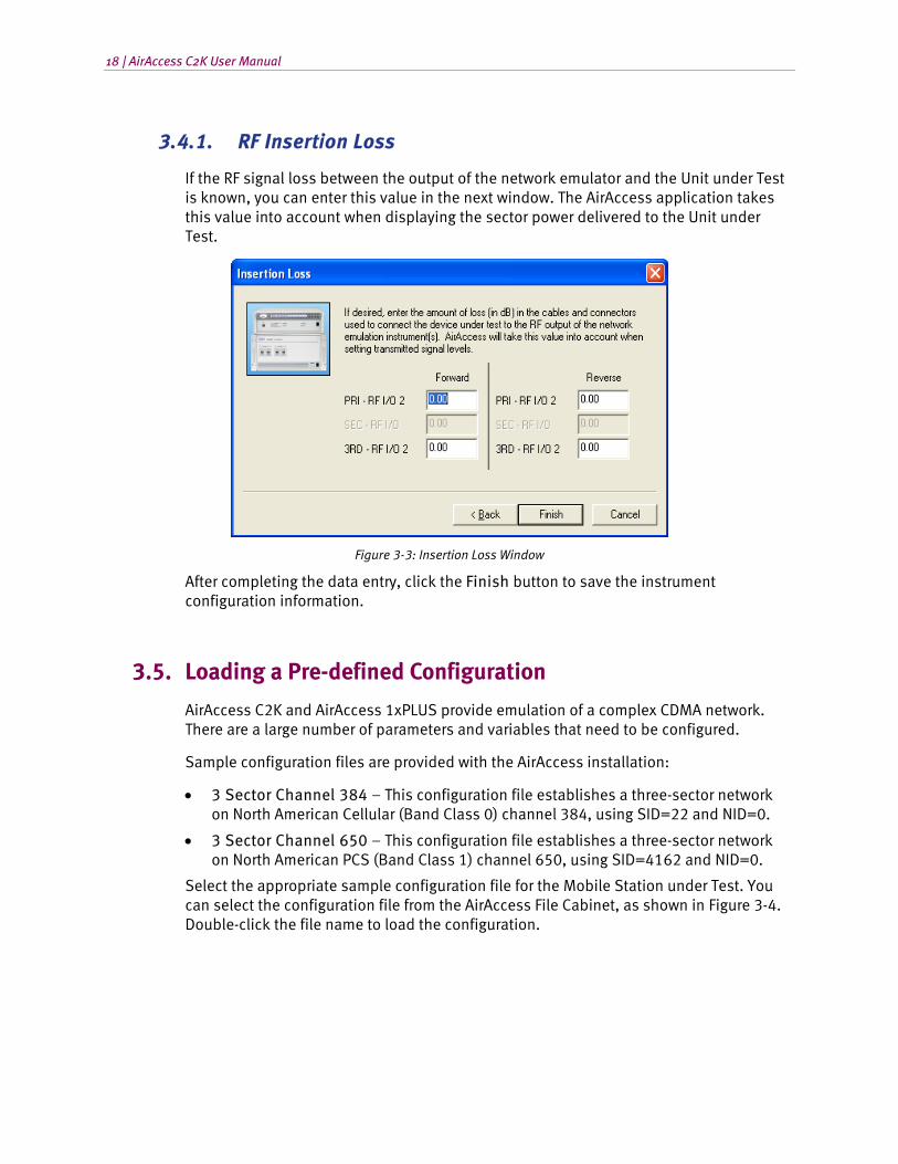
3.4.1. RF Insertion Loss
If the RF signal loss between the output of the network emulator and the Unit under Test is known, you can enter this value in the next window. The AirAccess application takes this value into account when displaying the sector power delivered to the Unit under Test.
Figure 3-3: Insertion Loss Window
After completing the data entry, click the Finish button to save the instrument configuration information.
3.5. Loading a Pre-defined Configuration
AirAccess C2K and AirAccess 1xPLUS provide emulation of a complex CDMA network. There are a large number of parameters and variables that need to be configured.
Sample configuration files are provided with the AirAccess installation:
• 3 Sector Channel 384 – This configuration file establishes a three-sector network on North American Cellular (Band Class 0) channel 384, using SID=22 and NID=0.
• 3 Sector Channel 650 – This configuration file establishes a three-sector network on North American PCS (Band Class 1) channel 650, using SID=4162 and NID=0.
Select the appropriate sample configuration file for the Mobile Station under Test. You can select the configuration file from the AirAccess File Cabinet, as shown in Figure 3-4. Double-click the file name to load the configuration.
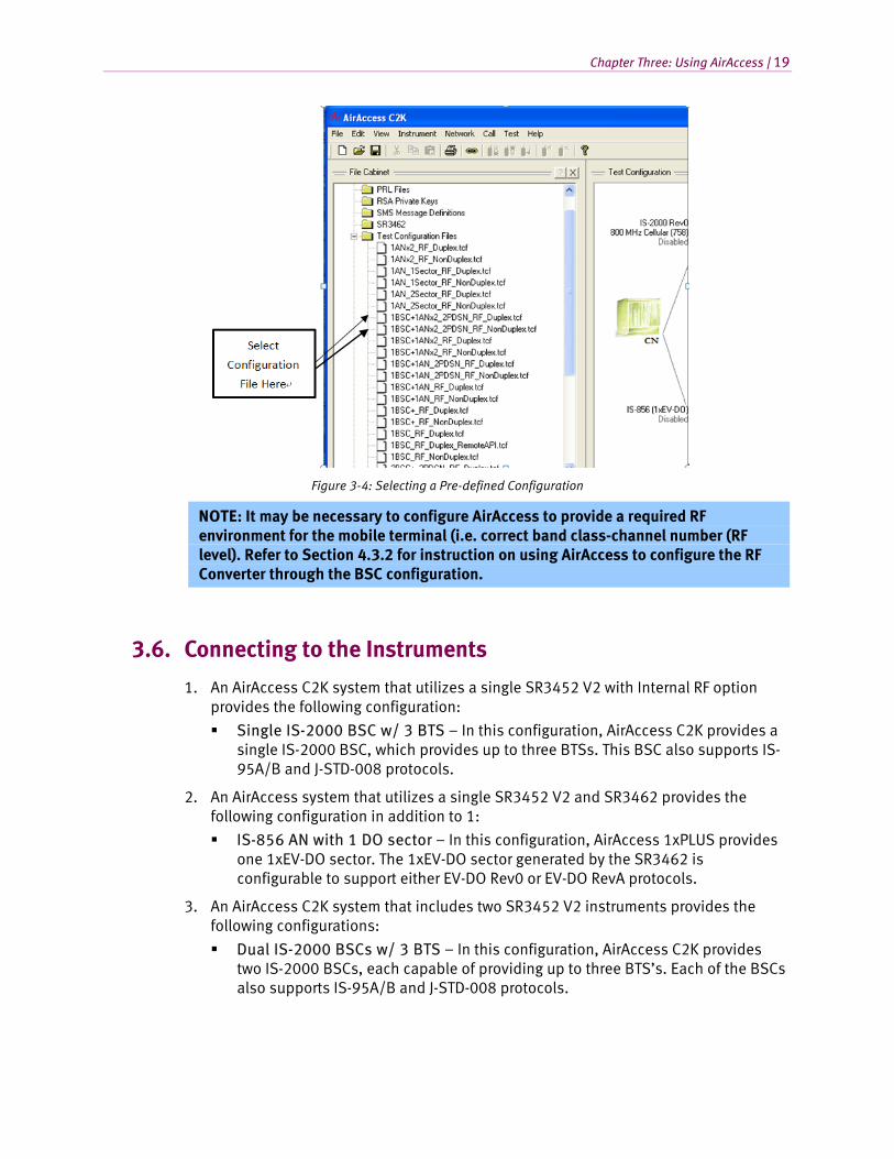
Chapter Three: Using AirAccess | 19
Figure 3-4: Selecting a Pre-defined Configuration
NOTE: It may be necessary to configure AirAccess to provide a required RF environment for the mobile terminal (i.e. correct band class-channel number (RF level). Refer to Section 4.3.2 for instruction on using AirAccess to configure the RF Converter through the BSC configuration.
3.6. Connecting to the Instruments
1. An AirAccess C2K system that utilizes a single SR3452 V2 with Internal RF option provides the following configuration:
Single IS-2000 BSC w/ 3 BTS – In this configuration, AirAccess C2K provides a single IS-2000 BSC, which provides up to three BTSs. This BSC also supports IS-95A/B and J-STD-008 protocols.
2. An AirAccess system that utilizes a single SR3452 V2 and SR3462 provides the following configuration in addition to 1:
IS-856 AN with 1 DO sector – In this configuration, AirAccess 1xPLUS provides one 1xEV-DO sector. The 1xEV-DO sector generated by the SR3462 is configurable to support either EV-DO Rev0 or EV-DO RevA protocols.
3. An AirAccess C2K system that includes two SR3452 V2 instruments provides the following configurations:
Dual IS-2000 BSCs w/ 3 BTS – In this configuration, AirAccess C2K provides two IS-2000 BSCs, each capable of providing up to three BTS’s. Each of the BSCs also supports IS-95A/B and J-STD-008 protocols.
20 | AirAccess C2K User Manual
Dual IS-2000 BSCs w/ 3 BTS, Dual PDSN – In this configuration, AirAccess C2K provides two IS-2000 BSCs, each capable of providing up to three BTS’s. Each of the BSCs also supports IS-95A/B and J-STD-008 protocols. A separate PDSN is implemented for each BSC, thus enabling inter-PDSN handoffs.
Single IS-2000 BSC w/ 6 BTS – In this configuration, AirAccess C2K provides a single IS-2000 BSC, which provides up to six BTS’s. This BSC also supports IS-95A/B and J-STD-008 protocols.
4. An AirAccess 1xPLUS system that utilizes two SR3452 V2 and SR3462 provides the following configurations in addition to 2 and 3:
IS-2000 BSC and IS-856 AN - In this configuration, AirAccess 1xPLUS provides one IS-2000 BSC and one 1xEV-DO sector. The IS-2000 BSC provides up to 3 BTSs, and also supports IS-95A/B and J-STD-008 protocols. The 1xEV-DO sector generated by the SR3462 is configurable to support either EV-DO Rev0 or EV-DO RevA protocols.
IS-2000 BSC and IS-856 AN, Dual PDSN - In this configuration, AirAccess 1xPLUS provides one IS-2000 BSC and one 1xEV-DO sector. The IS-2000 BSC provides up to 3 BTSs, and also supports IS-95A/B and J-STD-008 protocols. The 1xEV-DO sector generated by the SR3462 is configurable to support either EV-DO Rev0 or EV-DO RevA protocols. A separate PDSN is emulated for the BSC and the AN, enabling inter-PDSN handoff testing.
IS-856 AN with 2 DO sectors – In this configuration, AirAccess 1xPLUS provides two 1xEV-DO sectors. The 1xEV-DO sectors generated by the SR3462 are configurable to support either EV-DO Rev0 or EV-DO RevA protocols.
TIA-856-B AN with 1 DO sector – In this configuration, AirAccess 1xPLUS provides single 1xEV-DO RevB sector. The 1xEV-DO sector generated by SR3462 supports two carrier EV-DO RevB protocols.
5. An AirAccess system that utilizes a three SR3452 V2 and SR3462 provides the following configuration in addition to 4:
IS-2000 BSC and TIA-856-B AN - In this configuration, AirAccess 1xPLUS provides one IS-2000 BSC and one 1xEV-DO RevB sector. The IS-2000 BSC provides up to 3 BTSs, and also supports IS-95A/B and J-STD-008 protocols. The 1xEV-DO sector generated by SR3462 supports two carrier EV-DO RevB protocols.
IS-2000 BSC and TIA-856-B AN, Dual PDSN – In this configuration, AirAccess 1xPLUS provides one IS-2000 BSC and one 1xEV-DO RevB sector. The IS-2000 BSC provides up to 3 BTSs, and also supports IS-95A/B and J-STD-008 protocols. The 1xEV-DO sector generated by SR3462 supports two carrier EV-DO RevB protocols. A separate PDSN is emulated for the BSC and the AN, enabling inter-PDSN handoff testing.
Select one of the configurations from the drop-down menu at the top of the Test Configuration window in AirAccess, as shown in Figure 3-5.
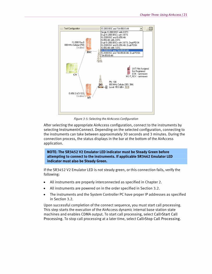
Chapter Three: Using AirAccess | 21
Figure 3-5: Selecting the AirAccess Configuration
After selecting the appropriate AirAccess configuration, connect to the instruments by selecting Instrument>Connect. Depending on the selected configuration, connecting to the instruments can take between approximately 30 seconds and 3 minutes. During the connection process, the status displays in the bar at the bottom of the AirAccess application.
NOTE: The SR3452 V2 Emulator LED indicator must be Steady Green before attempting to connect to the instruments. If applicable SR3462 Emulator LED indicator must also be Steady Green.
If the SR3452 V2 Emulator LED is not steady green, or this connection fails, verify the following:
• All instruments are properly interconnected as specified in Chapter 2.
• All instruments are powered on in the order specified in Section 3.2.
• The instruments and the System Controller PC have proper IP addresses as specified in Section 3.2.
Upon successful completion of the connect sequence, you must start call processing. This step starts the execution of the AirAccess dynamic internal base station state machines and enables CDMA output. To start call processing, select Call>Start Call Processing. To stop call processing at a later time, select Call>Stop Call Processing.
22 | AirAccess C2K User Manual
3.7. Registering a Mobile Station
After starting call processing, a mobile station cabled to the AirAccess instruments should acquire CDMA service as it would in a real network environment.
NOTE: The mobile station may not acquire CDMA service if it is not programmed to acquire service on the channel/SID/NID combination indicated by the selected AirAccess configuration file. The mobile station’s Preferred Roaming List (PRL) may need to be updated to match the selected configuration file.
After the mobile station has acquired CDMA service from AirAccess, you must identify the mobile station to AirAccess using a mobile station Access Channel message. In this case, a mobile station registration is used.
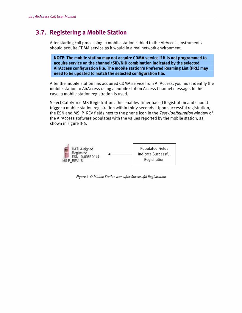
Select Call>Force MS Registration. This enables Timer-based Registration and should trigger a mobile station registration within thirty seconds. Upon successful registration, the ESN and MS_P_REV fields next to the phone icon in the Test Configuration window of the AirAccess software populates with the values reported by the mobile station, as shown in Figure 3-6.
Figure 3-6: Mobile Station Icon after Successful Registration
Populated Fields Indicate Successful
Registration
Chapter Three: Using AirAccess | 23
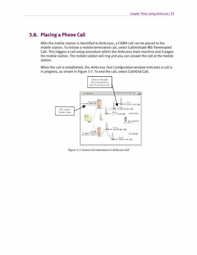
3.8. Placing a Phone Call
After the mobile station is identified to AirAccess, a CDMA call can be placed to the mobile station. To initiate a mobile-terminated call, select Call>Initiate MS-Terminated Call. This triggers a call setup procedure within the AirAccess state machine and it pages the mobile station. The mobile station will ring and you can answer the call at the mobile station.
When the call is established, the AirAccess Test Configuration window indicates a call is in progress, as shown in Figure 3-7. To end the call, select Call>End Call.
Figure 3-7: Active Call Indications in AirAccess GUI

4. Advanced Features
4.1. Overview
The AirAccess C2K software provides a feature-rich application capable of performing advanced CDMA testing. This section is designed to introduce the more advanced features of AirAccess C2K.
4.2. File Cabinet
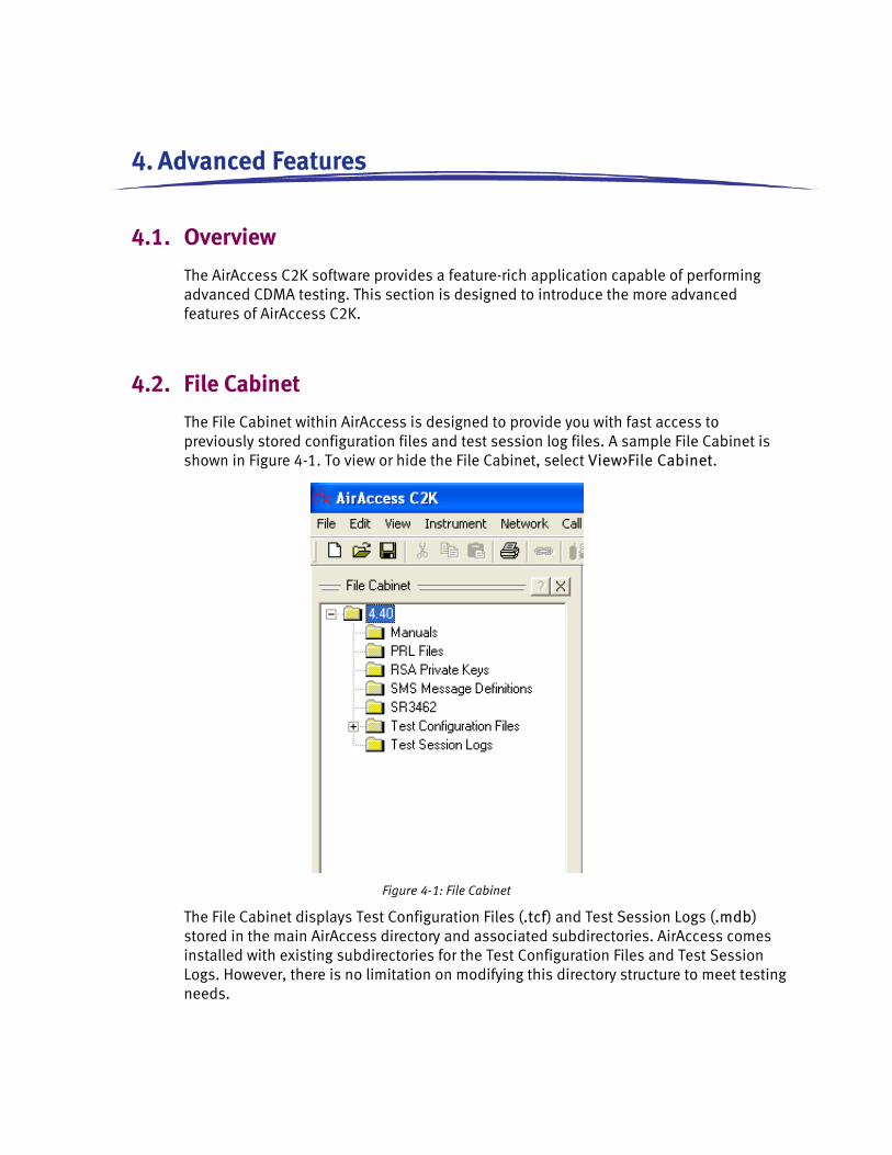
The File Cabinet within AirAccess is designed to provide you with fast access to previously stored configuration files and test session log files. A sample File Cabinet is shown in Figure 4-1. To view or hide the File Cabinet, select View>File Cabinet.
Figure 4-1: File Cabinet
The File Cabinet displays Test Configuration Files (.tcf) and Test Session Logs (.mdb) stored in the main AirAccess directory and associated subdirectories. AirAccess comes installed with existing subdirectories for the Test Configuration Files and Test Session Logs. However, there is no limitation on modifying this directory structure to meet testing needs.
26 | AirAccess C2K User Manual
4.2.1. Restoring a Test Configuration
To quickly restore a previously created test configuration from the File Cabinet, locate the file in the File Cabinet and double-click on the name. This automatically loads the saved configuration and parameters from the file when Call Processing is enabled.
4.2.2. Restoring a Test Session Log
To quickly restore a previously generated Test Session Log from the File Cabinet, locate the file in the File Cabinet and double-click on the name. This displays the stored Test Session log in the AirAccess Message Analyzer and Test Results windows.
4.3. Configuring Network Components
AirAccess is a powerful network emulator capable of providing emulation of a wide range of elements that make up a CDMA network. This includes:
• Base Station Transceiver Subsystems (BTSs)
• Base Station Controllers (BSCs)
• 1xEV-DO Sector
• 1xEV-DO Access Network (AN)
• Core Network (CN)
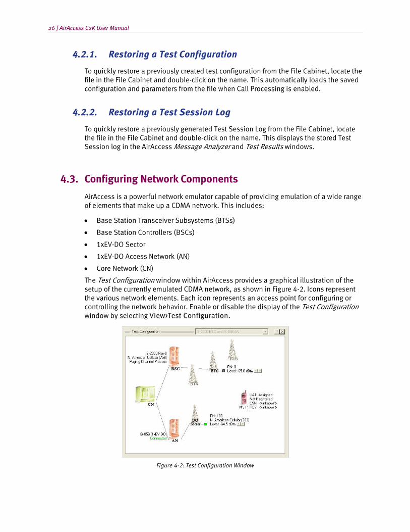
The Test Configuration window within AirAccess provides a graphical illustration of the setup of the currently emulated CDMA network, as shown in Figure 4-2. Icons represent the various network elements. Each icon represents an access point for configuring or controlling the network behavior. Enable or disable the display of the Test Configuration window by selecting View>Test Configuration.
Figure 4-2: Test Configuration Window
Chapter Four: Advanced Features | 27
An infrastructure-based model is used for navigating the configuration and control of AirAccess via the Test Configuration window. For example, in an infrastructure model, each BTS and EV-DO Sector can transmit an independent set of CDMA/EV-DO overhead messages. In the AirAccess implementation, each BTS and DO Sector icon provides the access point to configure independent sets of overhead messages. Authentication variables and procedures are core network-related in an infrastructure model. This means within AirAccess, the CN icon is the access point for setting authentication variables or launching authentication procedures.
Each icon has associated functionality that is accessed by either left and/or right mouse clicks. The following paragraphs describe the available functionality.
4.3.1. Base Station Transceiver Subsystem (BTS)
The BTS icon(s) in the Test Configuration window allows you to configure the following parameters:
• PN offset
• Sector power
• Parameters within overhead messages
• Enable or disable transmission of optional overhead messages
• Relative code channel gains
• Code channel Walsh codes
• Enable or disable the Quick Paging Channel
• Quasi-Orthogonal Function index (when QOF enabled at BSC)
• Add or remove a sector to/from soft handoff (dependent on current call state)
• Configure and trigger hard handoffs
Each BTS is configured independently. This means a change made at one BTS does not affect the configuration of another BTS.
NOTE: Some features and messages displayed in the Configure BTS window are dependent upon the protocol selected in the parent BSC configuration. When the TSB-74, J, STD, 008 or IS-95B protocol is selected, features and messages non-existent in these protocols are disabled.
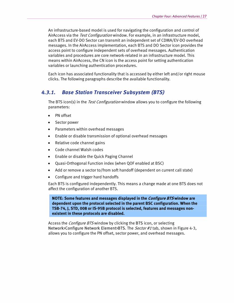
Access the Configure BTS window by clicking the BTS icon, or selecting Network>Configure Network Element>BTS. The Sector #1 tab, shown in Figure 4-3, allows you to configure the PN offset, sector power, and overhead messages.

28 | AirAccess C2K User Manual
Figure 4-3: BTS Configuration Window – Sector #1
In the Configure Sector section, you can enter the PN Offset and Sector Power (in dBm). To change the PN offset, Call Processing must be disabled. If Call Processing is not disabled, the PN Offset entry box will be disabled. To stop call processing, select Call>Stop Call Processing.
In the Configure Overhead Messages section, you can configure the following parameters:
• Sync Channel Message
• System Parameters Message
• Access Parameters Message
• CDMA Channel List Message
• Extended CDMA Channel List Message
• Neighbor List Message
• Extended Neighbor List Message
• General Neighbor List Message
• Extended System Parameters Message
• Global Service Redirection Message
• Extended Global Service Redirection Message
• User Zone Identification Message
• Private Neighbor List Message
To edit a message, select the desired message from the drop-down menu and make the desired changes. AirAccess automatically broadcasts the updated message(s) in the periodic overhead message train after the edits are complete.
In the Overhead Message Options section, the transmission of overhead messages not required by the CDMA specification can be enabled or disabled.
Chapter Four: Advanced Features | 29
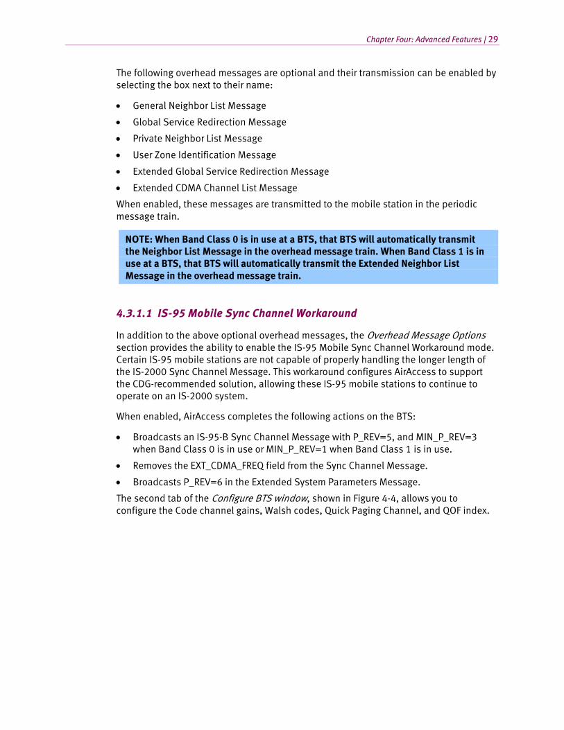
The following overhead messages are optional and their transmission can be enabled by selecting the box next to their name:
• General Neighbor List Message
• Global Service Redirection Message
• Private Neighbor List Message
• User Zone Identification Message
• Extended Global Service Redirection Message
• Extended CDMA Channel List Message
When enabled, these messages are transmitted to the mobile station in the periodic message train.
NOTE: When Band Class 0 is in use at a BTS, that BTS will automatically transmit the Neighbor List Message in the overhead message train. When Band Class 1 is in use at a BTS, that BTS will automatically transmit the Extended Neighbor List Message in the overhead message train.
4.3.1.1 IS-95 Mobile Sync Channel Workaround
In addition to the above optional overhead messages, the Overhead Message Options section provides the ability to enable the IS-95 Mobile Sync Channel Workaround mode. Certain IS-95 mobile stations are not capable of properly handling the longer length of the IS-2000 Sync Channel Message. This workaround configures AirAccess to support the CDG-recommended solution, allowing these IS-95 mobile stations to continue to operate on an IS-2000 system.
When enabled, AirAccess completes the following actions on the BTS:
• Broadcasts an IS-95-B Sync Channel Message with P_REV=5, and MIN_P_REV=3 when Band Class 0 is in use or MIN_P_REV=1 when Band Class 1 is in use.
• Removes the EXT_CDMA_FREQ field from the Sync Channel Message.
• Broadcasts P_REV=6 in the Extended System Parameters Message.
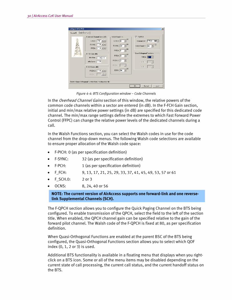
The second tab of the Configure BTS window, shown in Figure 4-4, allows you to configure the Code channel gains, Walsh codes, Quick Paging Channel, and QOF index.
30 | AirAccess C2K User Manual
Figure 4-4: BTS Configuration window – Code Channels
In the Overhead Channel Gains section of this window, the relative powers of the common code channels within a sector are entered (in dB). In the F-FCH Gain section, initial and min/max relative power settings (in dB) are specified for this dedicated code channel. The min/max range settings define the extremes to which Fast Forward Power Control (FFPC) can change the relative power levels of the dedicated channels during a call.
In the Walsh Functions section, you can select the Walsh codes in use for the code channel from the drop-down menus. The following Walsh code selections are available to ensure proper allocation of the Walsh code space:
• F-PICH: 0 (as per specification definition)
• F-SYNC: 32 (as per specification definition)
• F-PCH: 1 (as per specification definition)
• F_FCH: 9, 13, 17, 21, 25, 29, 33, 37, 41, 45, 49, 53, 57 or 61
• F_SCH.0: 2 or 3
• OCNS: 8, 24, 40 or 56
NOTE: The current version of AirAccess supports one forward-link and one reverse-link Supplemental Channels (SCH).
The F-QPCH section allows you to configure the Quick Paging Channel on the BTS being configured. To enable transmission of the QPCH, select the field to the left of the section title. When enabled, the QPCH channel gain can be specified relative to the gain of the forward pilot channel. The Walsh code of the F-QPCH is fixed at 80, as per specification definition.
When Quasi-Orthogonal Functions are enabled at the parent BSC of the BTS being configured, the Quasi-Orthogonal Functions section allows you to select which QOF index (0, 1, 2 or 3) is used.
Additional BTS functionality is available in a floating menu that displays when you right-click on a BTS icon. Some or all of the menu items may be disabled depending on the current state of call processing, the current call status, and the current handoff status on the BTS.
Chapter Four: Advanced Features | 31
Use the right-click menu to access the Add Sector(s) to Soft Handoff option, or select Test>Add Sector(s) to Soft Handoff. This opens a window where you can select and configure a Handoff Direction Message to be sent from AirAccess to the mobile station, and then attempt to add a sector identified in the Candidate Set to the Active Set. For a sector already part of a soft handoff, use the right-click menu to access the Remove Sector(s) from Soft Handoff option, or select Test>Remove Sector(s) from Soft Handoff. This opens a window where you can select and configure a Handoff Direction Message to be sent to the mobile station removing the sector from a soft handoff.
Hard handoffs can be configured and initiated by selecting Hard Handoff to Selected Sector(s) from the right-click menu, or selecting Test>Hard Handoff to Selected Sector(s). When this option is selected, a window displays allowing you to select the type of Handoff Direction Message to be used, and configure parameters within the message. Refer to Chapter 5 of this manual for more information on performing handoff tests.
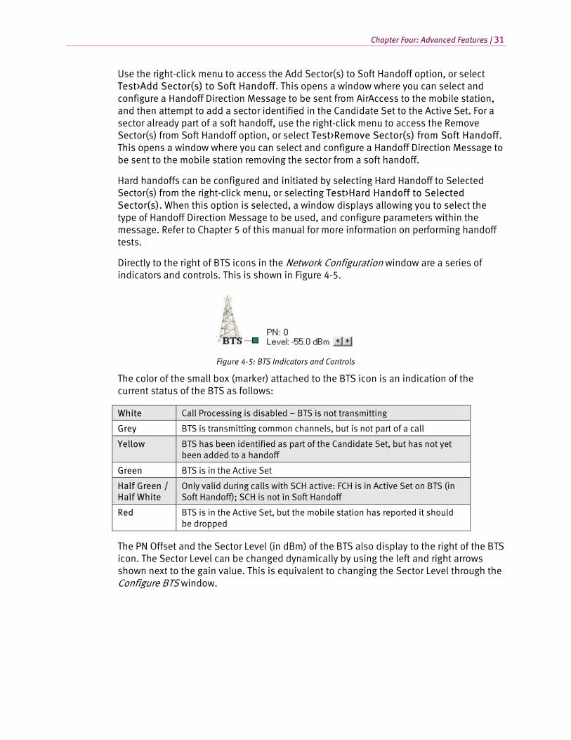
Directly to the right of BTS icons in the Network Configuration window are a series of indicators and controls. This is shown in Figure 4-5.
Figure 4-5: BTS Indicators and Controls
The color of the small box (marker) attached to the BTS icon is an indication of the current status of the BTS as follows:
White Call Processing is disabled – BTS is not transmitting
Grey BTS is transmitting common channels, but is not part of a call
Yellow BTS has been identified as part of the Candidate Set, but has not yet been added to a handoff
Green BTS is in the Active Set
Half Green / Half White
Only valid during calls with SCH active: FCH is in Active Set on BTS (in Soft Handoff); SCH is not in Soft Handoff
Red BTS is in the Active Set, but the mobile station has reported it should be dropped
The PN Offset and the Sector Level (in dBm) of the BTS also display to the right of the BTS icon. The Sector Level can be changed dynamically by using the left and right arrows shown next to the gain value. This is equivalent to changing the Sector Level through the Configure BTS window.
32 | AirAccess C2K User Manual
4.3.2. Base Station Controller (BSC)
The BSC icon(s) in the Test Configuration window allows you to configure the following parameters:
• Band class
• CDMA channel number
• Protocol revision
• RF power range
• Enable or disable Authentication, Encryption, Voice Privacy, and Quasi-Orthogonal Functions
• RF Loss timer value
• Number of automatic Layer 2 retries
• Add or remove BTS’s
• Service Negotiation
• Initiate and end calls
• Fast Forward Power Control (FFPC)
• RLP parameters
• View RLP statistics
Each BSC is configured independently. This means a change made at one BSC does not affect the configuration of another BSC.
Access the Configure 1X BSC window by clicking on a BSC icon, or by right-clicking the BSC icon and selecting Configure 1X BSC from the menu. You can also open the window by selecting Network>Configure 1X BSC. In the Configure BSC window, there are five tabs that provide access to configuration parameters:
1. General
2. Security
3. Power Control
4. RLP
5. Advanced
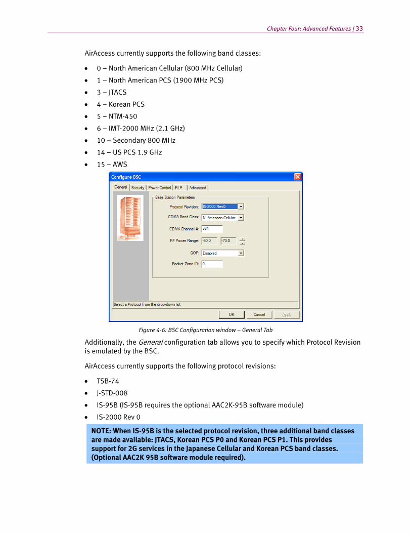
Figure 4-6 shows the General tab. Under this tab, you can enter the CDMA Band Class and CDMA Channel number.
Chapter Four: Advanced Features | 33
AirAccess currently supports the following band classes:
• 0 – North American Cellular (800 MHz Cellular)
• 1 – North American PCS (1900 MHz PCS)
• 3 – JTACS
• 4 – Korean PCS
• 5 – NTM-450
• 6 – IMT-2000 MHz (2.1 GHz)
• 10 – Secondary 800 MHz
• 14 – US PCS 1.9 GHz
• 15 – AWS
Figure 4-6: BSC Configuration window – General Tab
Additionally, the General configuration tab allows you to specify which Protocol Revision is emulated by the BSC.
AirAccess currently supports the following protocol revisions:
• TSB-74
• J-STD-008
• IS-95B (IS-95B requires the optional AAC2K-95B software module)
• IS-2000 Rev 0
NOTE: When IS-95B is the selected protocol revision, three additional band classes are made available: JTACS, Korean PCS P0 and Korean PCS P1. This provides support for 2G services in the Japanese Cellular and Korean PCS band classes. (Optional AAC2K 95B software module required).
34 | AirAccess C2K User Manual
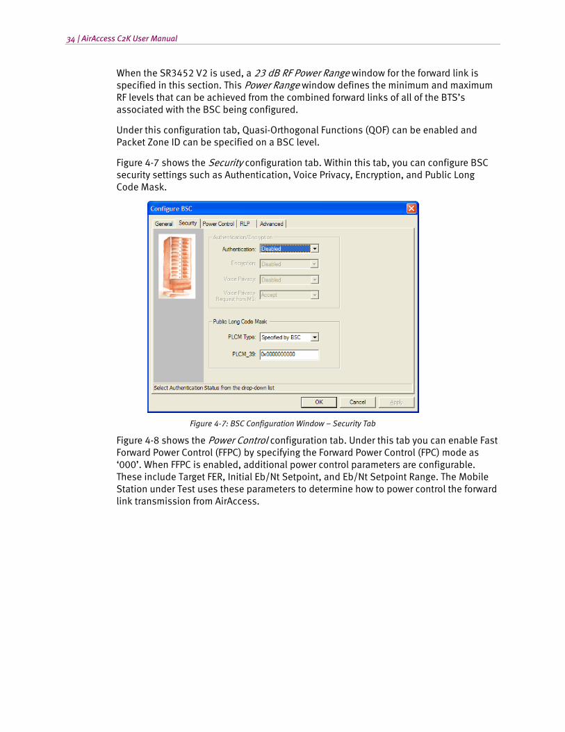
When the SR3452 V2 is used, a 23 dB RF Power Range window for the forward link is specified in this section. This Power Range window defines the minimum and maximum RF levels that can be achieved from the combined forward links of all of the BTS’s associated with the BSC being configured.
Under this configuration tab, Quasi-Orthogonal Functions (QOF) can be enabled and Packet Zone ID can be specified on a BSC level.
Figure 4-7 shows the Security configuration tab. Within this tab, you can configure BSC security settings such as Authentication, Voice Privacy, Encryption, and Public Long Code Mask.
Figure 4-7: BSC Configuration Window – Security Tab
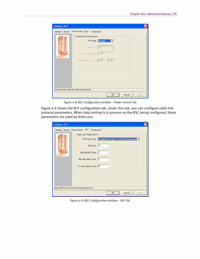
Figure 4-8 shows the Power Control configuration tab. Under this tab you can enable Fast Forward Power Control (FFPC) by specifying the Forward Power Control (FPC) mode as ‘000’. When FFPC is enabled, additional power control parameters are configurable. These include Target FER, Initial Eb/Nt Setpoint, and Eb/Nt Setpoint Range. The Mobile Station under Test uses these parameters to determine how to power control the forward link transmission from AirAccess.
Chapter Four: Advanced Features | 35
Figure 4-8: BSC Configuration window – Power Control Tab
Figure 4-9 shows the RLP configuration tab. Under this tab, you can configure radio link protocol parameters. When data testing is in process on the BSC being configured, these parameters are used by AirAccess.
Figure 4-9: BSC Configuration window – RLP Tab
36 | AirAccess C2K User Manual
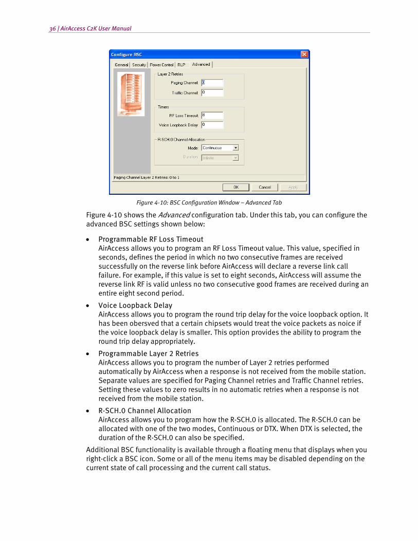
Figure 4-10: BSC Configuration Window – Advanced Tab
Figure 4-10 shows the Advanced configuration tab. Under this tab, you can configure the advanced BSC settings shown below:
• Programmable RF Loss Timeout AirAccess allows you to program an RF Loss Timeout value. This value, specified in seconds, defines the period in which no two consecutive frames are received successfully on the reverse link before AirAccess will declare a reverse link call failure. For example, if this value is set to eight seconds, AirAccess will assume the reverse link RF is valid unless no two consecutive good frames are received during an entire eight second period.
• Voice Loopback Delay AirAccess allows you to program the round trip delay for the voice loopback option. It has been obersved that a certain chipsets would treat the voice packets as noice if the voice loopback delay is smaller. This option provides the ability to program the round trip delay appropriately.
• Programmable Layer 2 Retries AirAccess allows you to program the number of Layer 2 retries performed automatically by AirAccess when a response is not received from the mobile station. Separate values are specified for Paging Channel retries and Traffic Channel retries. Setting these values to zero results in no automatic retries when a response is not received from the mobile station.
• R-SCH.0 Channel Allocation AirAccess allows you to program how the R-SCH.0 is allocated. The R-SCH.0 can be allocated with one of the two modes, Continuous or DTX. When DTX is selected, the duration of the R-SCH.0 can also be specified.
Additional BSC functionality is available through a floating menu that displays when you right-click a BSC icon. Some or all of the menu items may be disabled depending on the current state of call processing and the current call status.
Chapter Four: Advanced Features | 37
Use the right-click menu to access the Add 1X BTS option. This adds a BTS to the BSC being configured, if BTS resources are available. Select the Delete 1X BTS option from the right-click menu to remove the most recently added BTS. Refer to Section 4.4 for more information on modifying network topology.
The Configure Service Negotiation window is also accessible from the right-click menu. This is the equivalent of Network>Configure 1X Service Negotiation. Refer to Section 4.8 for more information on configuring service negotiation within AirAccess. Mobile-terminated calls can be initiated from the right-click menu. Once a call is established, it can be ended from the right-click menu. Display RLP statistics by selecting View RLP Statistics from the right-click menu. You can also select View>RLP Statistics.
• Packet Zone ID Under the General configuration tab, AirAccess allows you to program the Packet Zone ID on a per BSC basis. This allows each of the BSCs in a two BSC AirAccess configuration to be configured with different Packet Zone IDs; enabling emulation of handoffs between PDSNs.
• Voice Privacy Settings When Authentication is enabled under the Security configuration tab of a BSC, you have the ability to set the behavior of AirAccess for both network-initiated and mobile-initiated transitions to voice privacy. The Voice Privacy setting in the General configuration tab specifies the network-initiated behavior. When set to Enabled, AirAccess attempts to transition to a private long code mask at the start of a call (assuming the mobile set the Privacy Mode (PM) bit in the Origination or Page Response Message) or when the setting is changed during a call. The Voice Privacy Request from MS setting in this tab specifies the AirAccess response to a mobile-initiated transition. When set to “Accept”, AirAccess allows a mobile-initiated request to transition to a private long code mask.
4.3.3. 1xEV-DO Sector
The DO Sector icon(s) in the Test Configuration window allows you to configure the following parameters:
• CDMA band class
• CDMA channel number(s)
• Level
• SectorID
• Control Channel Rate
• RAB Length
• RAB Offset
• Parameters within Overhead Messages
• Disable RF Transmission and/or Reception
• EV-DO RevB Multi-Carrier Parameters
38 | AirAccess C2K User Manual
Each DO Sector is configured independently. This means a change made at one DO Sector does not affect the configuration of another DO Sector.
NOTE: In case of EV-DO RevB, AirAccess emulates only one DO Sector with or without the presence of one BSC.
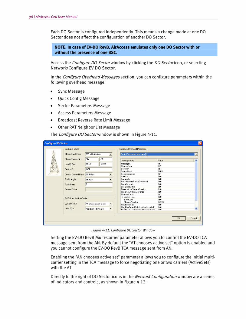
Access the Configure DO Sector window by clicking the DO Sector icon, or selecting Network>Configure EV DO Sector.
In the Configure Overhead Messages section, you can configure parameters within the following overhead message:
• Sync Message
• Quick Config Message
• Sector Parameters Message
• Access Parameters Message
• Broadcast Reverse Rate Limit Message
• Other RAT Neighbor List Message
The Configure DO Sector window is shown in Figure 4-11.
Figure 4-11: Configure DO Sector Window
Setting the EV-DO RevB Multi-Carrier parameter allows you to control the EV-DO TCA message sent from the AN. By default the "AT chooses active set" option is enabled and you cannot configure the EV-DO RevB TCA message sent from AN.
Enabling the "AN chooses active set" parameter allows you to configure the initial multi-carrier setting in the TCA message to force negotiating one or two carriers (ActiveSets) with the AT.
Directly to the right of DO Sector icons in the Network Configuration window are a series of indicators and controls, as shown in Figure 4-12.
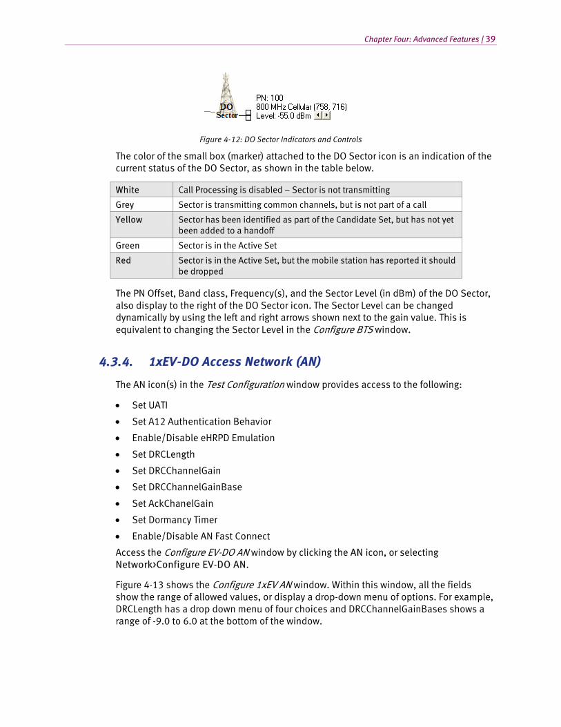
Chapter Four: Advanced Features | 39
Figure 4-12: DO Sector Indicators and Controls
The color of the small box (marker) attached to the DO Sector icon is an indication of the current status of the DO Sector, as shown in the table below.
White Call Processing is disabled – Sector is not transmitting
Grey Sector is transmitting common channels, but is not part of a call
Yellow Sector has been identified as part of the Candidate Set, but has not yet been added to a handoff
Green Sector is in the Active Set
Red Sector is in the Active Set, but the mobile station has reported it should be dropped
The PN Offset, Band class, Frequency(s), and the Sector Level (in dBm) of the DO Sector, also display to the right of the DO Sector icon. The Sector Level can be changed dynamically by using the left and right arrows shown next to the gain value. This is equivalent to changing the Sector Level in the Configure BTS window.
4.3.4. 1xEV-DO Access Network (AN)
The AN icon(s) in the Test Configuration window provides access to the following:
• Set UATI
• Set A12 Authentication Behavior
• Enable/Disable eHRPD Emulation
• Set DRCLength
• Set DRCChannelGain
• Set DRCChannelGainBase
• Set AckChanelGain
• Set Dormancy Timer
• Enable/Disable AN Fast Connect
Access the Configure EV-DO AN window by clicking the AN icon, or selecting Network>Configure EV-DO AN.
Figure 4-13 shows the Configure 1xEV AN window. Within this window, all the fields show the range of allowed values, or display a drop-down menu of options. For example, DRCLength has a drop down menu of four choices and DRCChannelGainBases shows a range of -9.0 to 6.0 at the bottom of the window.
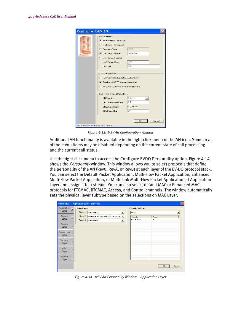
40 | AirAccess C2K User Manual
Figure 4-13: 1xEV AN Configuration Window
Additional AN functionality is available in the right-click menu of the AN icon. Some or all of the menu items may be disabled depending on the current state of call processing and the current call status.
Use the right-click menu to access the Configure EVDO Personality option. Figure 4-14 shows the Personality window. This window allows you to select protocols that define the personality of the AN (Rev0, RevA, or RevB) at each layer of the EV-DO protocol stack. You can select the Default Packet Application, Multi-Flow Packet Application, Enhanced Multi-Flow Packet Application, or Multi-Link Multi-Flow Packet Application at Application Layer and assign it to a stream. You can also select default MAC or Enhanced MAC protocols for FTCMAC, RTCMAC, Access, and Control channels. The window automatically sets the physical layer subtype based on the selections on MAC Layer.
Figure 4-14: 1xEV AN Personality Window – Application Layer
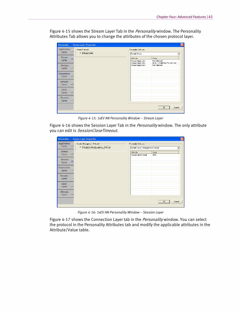
Chapter Four: Advanced Features | 41
Figure 4-15 shows the Stream Layer Tab in the Personality window. The Personality Attributes Tab allows you to change the attributes of the chosen protocol layer.
Figure 4-15: 1xEV AN Personality Window – Stream Layer
Figure 4-16 shows the Session Layer Tab in the Personality window. The only attribute you can edit is SessionCloseTimeout.
Figure 4-16: 1xEV AN Personality Window – Session Layer
Figure 4-17 shows the Connection Layer tab in the Personality window. You can select the protocol in the Personality Attributes tab and modify the applicable attributes in the Attribute/Value table.
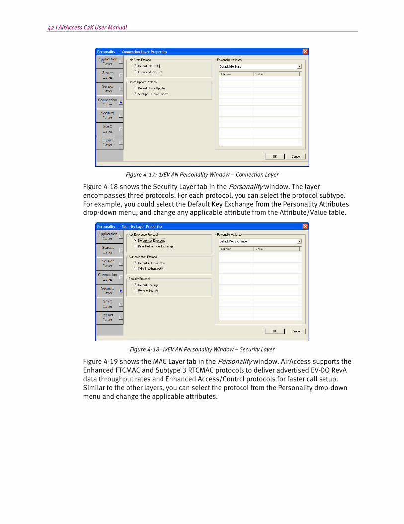
42 | AirAccess C2K User Manual
Figure 4-17: 1xEV AN Personality Window – Connection Layer
Figure 4-18 shows the Security Layer tab in the Personality window. The layer encompasses three protocols. For each protocol, you can select the protocol subtype. For example, you could select the Default Key Exchange from the Personality Attributes drop-down menu, and change any applicable attribute from the Attribute/Value table.
Figure 4-18: 1xEV AN Personality Window – Security Layer
Figure 4-19 shows the MAC Layer tab in the Personality window. AirAccess supports the Enhanced FTCMAC and Subtype 3 RTCMAC protocols to deliver advertised EV-DO RevA data throughput rates and Enhanced Access/Control protocols for faster call setup. Similar to the other layers, you can select the protocol from the Personality drop-down menu and change the applicable attributes.
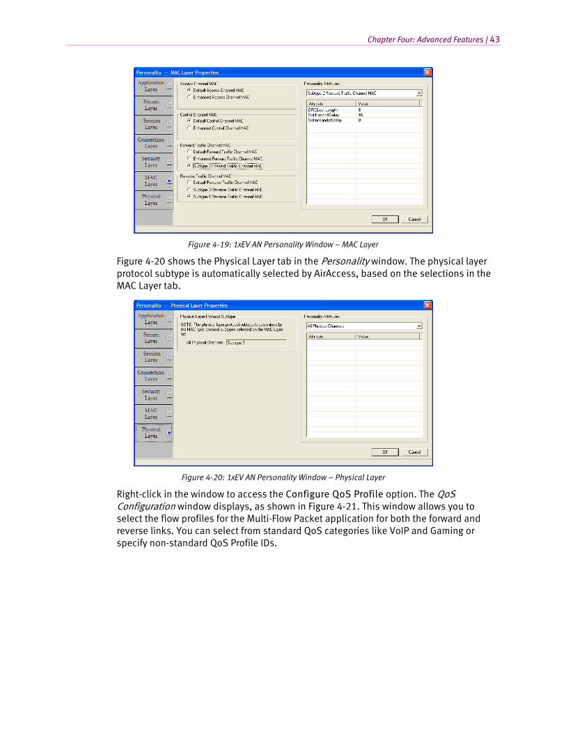
Chapter Four: Advanced Features | 43
Figure 4-19: 1xEV AN Personality Window – MAC Layer
Figure 4-20 shows the Physical Layer tab in the Personality window. The physical layer protocol subtype is automatically selected by AirAccess, based on the selections in the MAC Layer tab.
Figure 4-20: 1xEV AN Personality Window – Physical Layer
Right-click in the window to access the Configure QoS Profile option. The QoS Configuration window displays, as shown in Figure 4-21. This window allows you to select the flow profiles for the Multi-Flow Packet application for both the forward and reverse links. You can select from standard QoS categories like VoIP and Gaming or specify non-standard QoS Profile IDs.
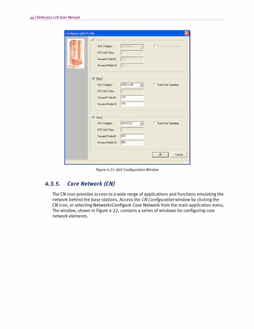
44 | AirAccess C2K User Manual
Figure 4-21: QoS Configuration Window
4.3.5. Core Network (CN)
The CN icon provides access to a wide range of applications and functions emulating the network behind the base stations. Access the CN Configuration window by clicking the CN icon, or selecting Network>Configure Core Network from the main application menu. The window, shown in Figure 4-22, contains a series of windows for configuring core network elements.
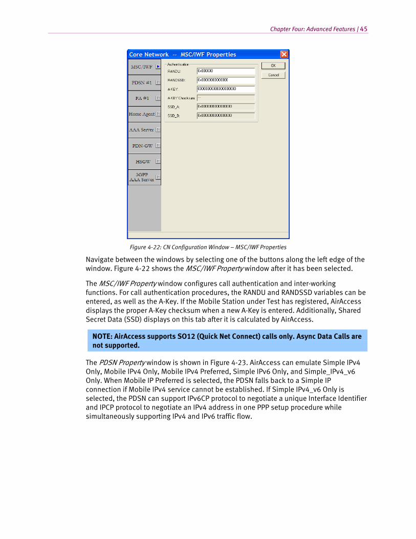
Chapter Four: Advanced Features | 45
Figure 4-22: CN Configuration Window – MSC/IWF Properties
Navigate between the windows by selecting one of the buttons along the left edge of the window. Figure 4-22 shows the MSC/IWF Property window after it has been selected.
The MSC/IWF Property window configures call authentication and inter-working functions. For call authentication procedures, the RANDU and RANDSSD variables can be entered, as well as the A-Key. If the Mobile Station under Test has registered, AirAccess displays the proper A-Key checksum when a new A-Key is entered. Additionally, Shared Secret Data (SSD) displays on this tab after it is calculated by AirAccess.
NOTE: AirAccess supports SO12 (Quick Net Connect) calls only. Async Data Calls are not supported.
The PDSN Property window is shown in Figure 4-23. AirAccess can emulate Simple IPv4 Only, Mobile IPv4 Only, Mobile IPv4 Preferred, Simple IPv6 Only, and Simple_IPv4_v6 Only. When Mobile IP Preferred is selected, the PDSN falls back to a Simple IP connection if Mobile IPv4 service cannot be established. If Simple IPv4_v6 Only is selected, the PDSN can support IPv6CP protocol to negotiate a unique Interface Identifier and IPCP protocol to negotiate an IPv4 address in one PPP setup procedure while simultaneously supporting IPv4 and IPv6 traffic flow.
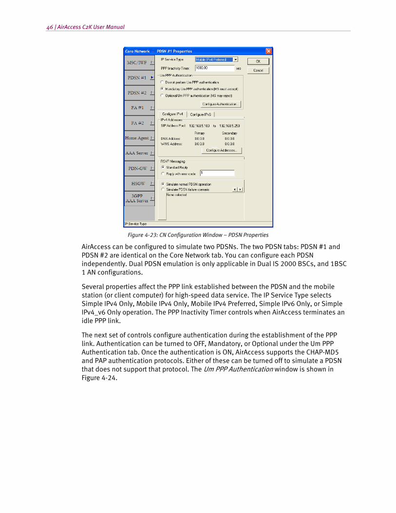
46 | AirAccess C2K User Manual
Figure 4-23: CN Configuration Window – PDSN Properties
AirAccess can be configured to simulate two PDSNs. The two PDSN tabs: PDSN #1 and PDSN #2 are identical on the Core Network tab. You can configure each PDSN independently. Dual PDSN emulation is only applicable in Dual IS 2000 BSCs, and 1BSC 1 AN configurations.
Several properties affect the PPP link established between the PDSN and the mobile station (or client computer) for high-speed data service. The IP Service Type selects Simple IPv4 Only, Mobile IPv4 Only, Mobile IPv4 Preferred, Simple IPv6 Only, or Simple IPv4_v6 Only operation. The PPP Inactivity Timer controls when AirAccess terminates an idle PPP link.
The next set of controls configure authentication during the establishment of the PPP link. Authentication can be turned to OFF, Mandatory, or Optional under the Um PPP Authentication tab. Once the authentication is ON, AirAccess supports the CHAP-MD5 and PAP authentication protocols. Either of these can be turned off to simulate a PDSN that does not support that protocol. The Um PPP Authentication window is shown in Figure 4-24.
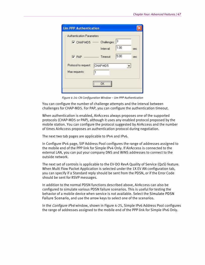
Chapter Four: Advanced Features | 47
Figure 4-24: CN Configuration Window – Um PPP Authentication
You can configure the number of challenge attempts and the interval between challenges for CHAP-MD5. For PAP, you can configure the authentication timeout.
When authentication is enabled, AirAccess always proposes one of the supported protocols (CHAP-MD5 or PAP), although it uses any enabled protocol proposed by the mobile station. You can configure the protocol suggested by AirAccess and the number of times AirAccess proposes an authentication protocol during negotiation.
The next two tab pages are applicable to IPv4 and IPv6.
In Configure IPv4 page, SIP Address Pool configures the range of addresses assigned to the mobile end of the PPP link for Simple IPv4 Only. If AirAccess is connected to the external LAN, you can put your company DNS and WINS addresses to connect to the outside network.
The next set of controls is applicable to the EV-DO RevA Quality of Service (QoS) feature. When Multi Flow Packet Application is selected under the 1X EV AN configuration tab, you can specify if a Standard reply should be sent from the PDSN, or if the Error Code should be sent for RSVP messages.
In addition to the normal PDSN functions described above, AirAccess can also be configured to simulate various PDSN failure scenarios. This is useful for testing the behavior of a mobile device when service is not available. Select the Simulate PDSN Failure Scenario, and use the arrow keys to select one of the scenarios.
In the Configure IPv6 window, shown in Figure 4-25, Simple IPv6 Address Pool configures the range of addresses assigned to the mobile end of the PPP link for Simple IPv6 Only.

48 | AirAccess C2K User Manual
Figure 4-25: CN Configuration Window – PDSN IPv6 Properties
The second group is controls for configuring ICMPv6 behavior. The first option determines whether the emulator responds to Router Solicitation Messages sent by the UE. The second option controls the transmission of unsolicited Router Advertisement messages.
Figure 4-26 shows the Property window for the Mobile IP Foreign Agent (FA) emulation. When AirAccess is configured for two PDSN operations, two Foreign Agent windows are available. This allows you to independently configure the behavior of each PDSN/FA. The first Foreign Agent is used for calls on the first BSC, and the second Foreign Agent is used to calls on the second BSC.
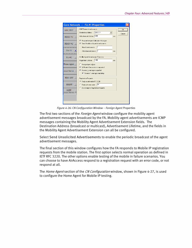
Chapter Four: Advanced Features | 49
Figure 4-26: CN Configuration Window – Foreign Agent Properties
The first two sections of the Foreign Agent window configure the mobility agent advertisement messages broadcast by the FA. Mobility agent advertisements are ICMP messages containing the Mobility Agent Advertisement Extension fields. The Destination Address (broadcast or multicast), Advertisement Lifetime, and the fields in the Mobility Agent Advertisement Extension can all be configured.
Select Send Unsolicited Advertisements to enable the periodic broadcast of the agent advertisement messages.
The final section of this window configures how the FA responds to Mobile IP registration requests from the mobile station. The first option selects normal operation as defined in IETF RFC 3220. The other options enable testing of the mobile in failure scenarios. You can choose to have AirAccess respond to a registration request with an error code, or not respond at all.
The Home Agent section of the CN Configuration window, shown in Figure 4-27, is used to configure the Home Agent for Mobile IP testing.
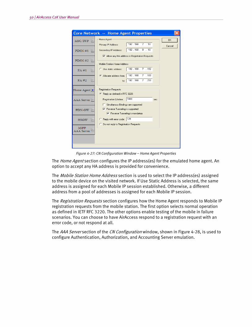
50 | AirAccess C2K User Manual
Figure 4-27: CN Configuration Window – Home Agent Properties
The Home Agent section configures the IP address(es) for the emulated home agent. An option to accept any HA address is provided for convenience.
The Mobile Station Home Address section is used to select the IP address(es) assigned to the mobile device on the visited network. If Use Static Address is selected, the same address is assigned for each Mobile IP session established. Otherwise, a different address from a pool of addresses is assigned for each Mobile IP session.
The Registration Requests section configures how the Home Agent responds to Mobile IP registration requests from the mobile station. The first option selects normal operation as defined in IETF RFC 3220. The other options enable testing of the mobile in failure scenarios. You can choose to have AirAccess respond to a registration request with an error code, or not respond at all.
The AAA Server section of the CN Configuration window, shown in Figure 4-28, is used to configure Authentication, Authorization, and Accounting Server emulation.
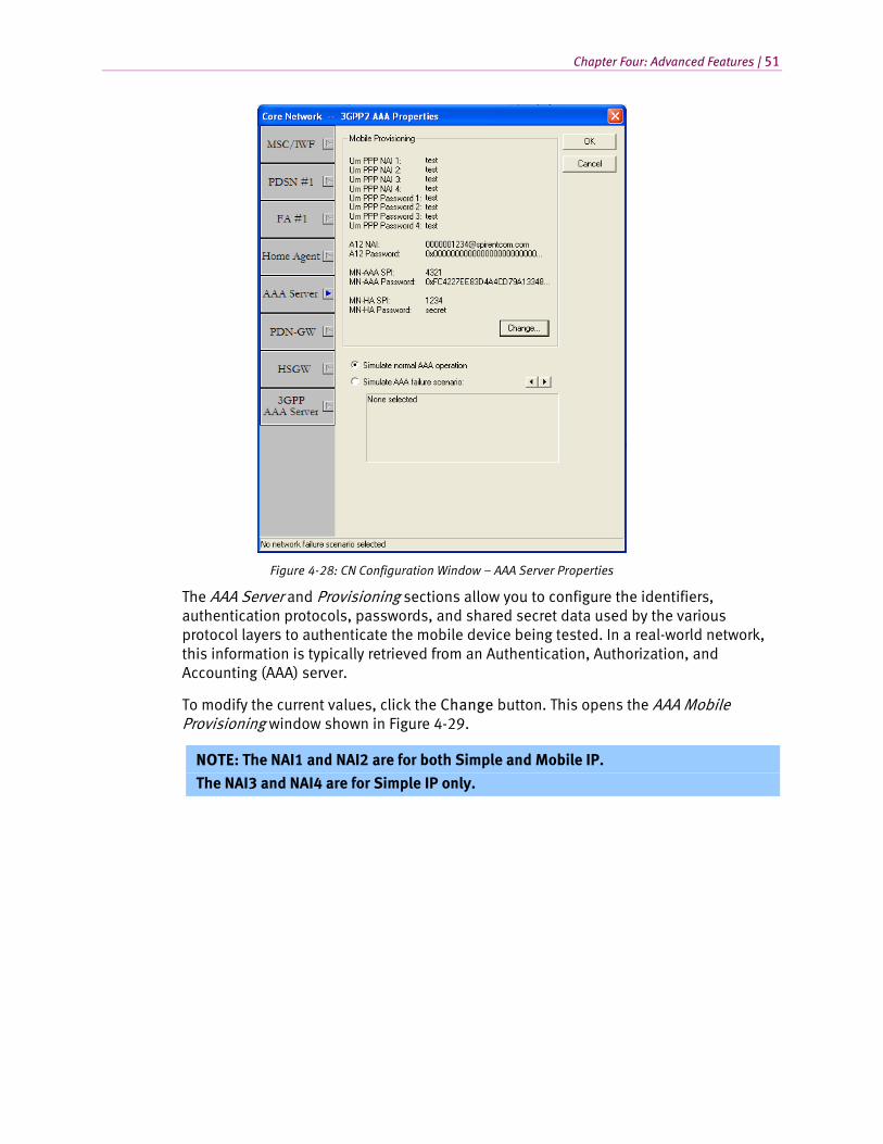
Chapter Four: Advanced Features | 51
Figure 4-28: CN Configuration Window – AAA Server Properties
The AAA Server and Provisioning sections allow you to configure the identifiers, authentication protocols, passwords, and shared secret data used by the various protocol layers to authenticate the mobile device being tested. In a real-world network, this information is typically retrieved from an Authentication, Authorization, and Accounting (AAA) server.
To modify the current values, click the Change button. This opens the AAA Mobile Provisioning window shown in Figure 4-29.
NOTE: The NAI1 and NAI2 are for both Simple and Mobile IP.
The NAI3 and NAI4 are for Simple IP only.
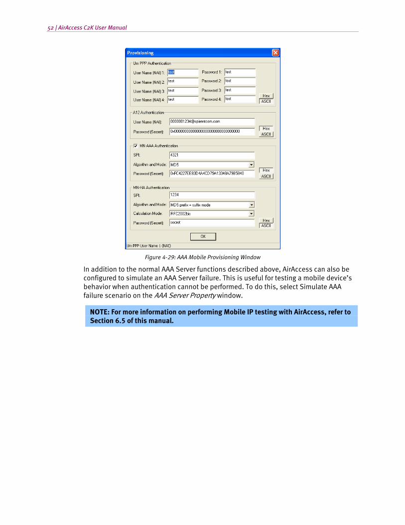
52 | AirAccess C2K User Manual
Figure 4-29: AAA Mobile Provisioning Window
In addition to the normal AAA Server functions described above, AirAccess can also be configured to simulate an AAA Server failure. This is useful for testing a mobile device’s behavior when authentication cannot be performed. To do this, select Simulate AAA failure scenario on the AAA Server Property window.
NOTE: For more information on performing Mobile IP testing with AirAccess, refer to Section 6.5 of this manual.
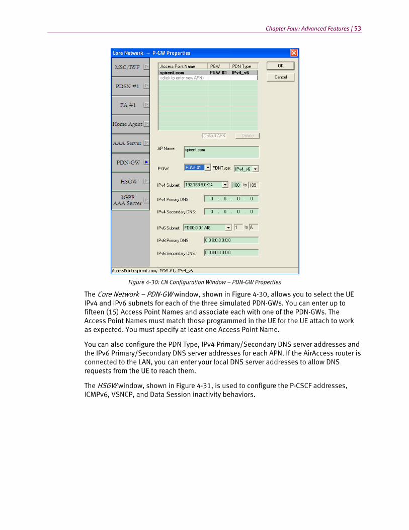
Chapter Four: Advanced Features | 53
Figure 4-30: CN Configuration Window – PDN-GW Properties
The Core Network – PDN-GW window, shown in Figure 4-30, allows you to select the UE IPv4 and IPv6 subnets for each of the three simulated PDN-GWs. You can enter up to fifteen (15) Access Point Names and associate each with one of the PDN-GWs. The Access Point Names must match those programmed in the UE for the UE attach to work as expected. You must specify at least one Access Point Name.
You can also configure the PDN Type, IPv4 Primary/Secondary DNS server addresses and the IPv6 Primary/Secondary DNS server addresses for each APN. If the AirAccess router is connected to the LAN, you can enter your local DNS server addresses to allow DNS requests from the UE to reach them.
The HSGW window, shown in Figure 4-31, is used to configure the P-CSCF addresses, ICMPv6, VSNCP, and Data Session inactivity behaviors.
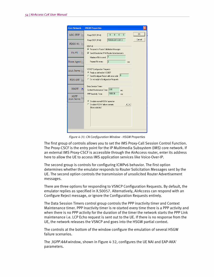
54 | AirAccess C2K User Manual
Figure 4-31: CN Configuration Window - HSGW Properties
The first group of controls allows you to set the IMS Proxy-Call Session Control Function. The Proxy-CSCF is the entry point for the IP Multimedia Subsystem (IMS) core network. If an external IMS Proxy-CSCF is accessible through the AirAccess router, enter its address here to allow the UE to access IMS application services like Voice-Over-IP.
The second group is controls for configuring ICMPv6 behavior. The first option determines whether the emulator responds to Router Solicitation Messages sent by the UE. The second option controls the transmission of unsolicited Router Advertisement messages.
There are three options for responding to VSNCP Configuration Requests. By default, the emulator replies as specified in X.S0057. Alternatively, AirAccess can respond with an Configure Reject message, or ignore the Configuration Requests entirely.
The Data Session Timers control group controls the PPP inactivity timer and Context Maintenance timer. PPP Inactivity timer is re-started every time there is a PPP activity and when there is no PPP activity for the duration of the timer the network starts the PPP Link maintenance i.e. LCP Echo request is sent out to the UE. If there is no response from the UE, the network releases the VSNCP and goes into the HSGW partial context.
The controls at the bottom of the window configure the emulation of several HSGW failure scenarios.
The 3GPP AAA window, shown in Figure 4-32, configures the UE NAI and EAP-AKA' parameters.
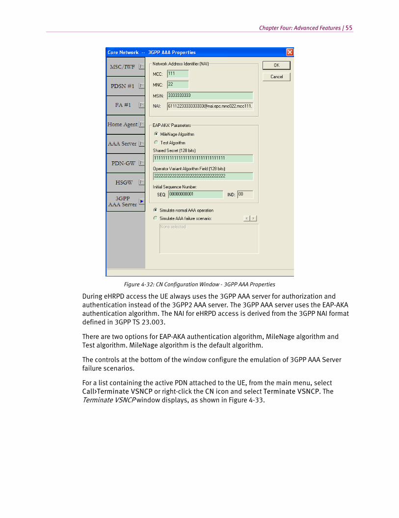
Chapter Four: Advanced Features | 55
Figure 4-32: CN Configuration Window - 3GPP AAA Properties
During eHRPD access the UE always uses the 3GPP AAA server for authorization and authentication instead of the 3GPP2 AAA server. The 3GPP AAA server uses the EAP-AKA authentication algorithm. The NAI for eHRPD access is derived from the 3GPP NAI format defined in 3GPP TS 23.003.
There are two options for EAP-AKA authentication algorithm, MileNage algorithm and Test algorithm. MileNage algorithm is the default algorithm.
The controls at the bottom of the window configure the emulation of 3GPP AAA Server failure scenarios.
For a list containing the active PDN attached to the UE, from the main menu, select Call>Terminate VSNCP or right-click the CN icon and select Terminate VSNCP. The Terminate VSNCP window displays, as shown in Figure 4-33.
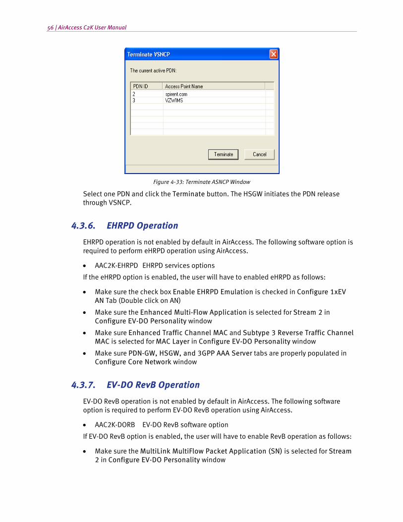
56 | AirAccess C2K User Manual
Figure 4-33: Terminate ASNCP Window
Select one PDN and click the Terminate button. The HSGW initiates the PDN release through VSNCP.
4.3.6. EHRPD Operation
EHRPD operation is not enabled by default in AirAccess. The following software option is required to perform eHRPD operation using AirAccess.
• AAC2K-EHRPD EHRPD services options
If the eHRPD option is enabled, the user will have to enabled eHRPD as follows:
• Make sure the check box Enable EHRPD Emulation is checked in Configure 1xEV AN Tab (Double click on AN)
• Make sure the Enhanced Multi-Flow Application is selected for Stream 2 in Configure EV-DO Personality window
• Make sure Enhanced Traffic Channel MAC and Subtype 3 Reverse Traffic Channel MAC is selected for MAC Layer in Configure EV-DO Personality window
• Make sure PDN-GW, HSGW, and 3GPP AAA Server tabs are properly populated in Configure Core Network window
4.3.7. EV-DO RevB Operation
EV-DO RevB operation is not enabled by default in AirAccess. The following software option is required to perform EV-DO RevB operation using AirAccess.
• AAC2K-DORB EV-DO RevB software option
If EV-DO RevB option is enabled, the user will have to enable RevB operation as follows:
• Make sure the MultiLink MultiFlow Packet Application (SN) is selected for Stream 2 in Configure EV-DO Personality window
Chapter Four: Advanced Features | 57
• Make sure Subtype 1 Route Update protocol check box is checked for Connection Layer in Configure EV-DO Personality window
• Make sure Subtype 2 Forward Traffic Channel MAC and Subtype 4 Reverse Traffic Channel MAC check boxes are checked for MAC layer in Configure EV-DO Personality window
• Make sure the CDMA Channel #(s) are assigned properly in Configure DO Sector window. Please remember that for efficient EV-DO RevB operation the recommended channel spacing is 42 channels or 1.25MHz. It is not advisable for the channels to be more than 5MHz apart for efficient operation even though AirAccess does not enforce this restriction.
4.3.8. Saving and Recalling Test Configurations
AirAccess stores all parameters used for network emulation configuration in a single database. The contents of the current AirAccess configuration can be saved and recalled at a future date.
To save a Test Configuration:
Select File>Save Test Configuration. This opens a window where you can select a directory and filename to store the database.
To recall a Test Configuration:
Select File>Recall Test Configuration. This opens a window where you can browse for the desired database. Once selected, the database contents are automatically used to update the configuration of AirAccess.
4.3.9. Mobile Station (MS)
Although not specifically part of the network emulation provided by AirAccess, the MS icon provides access to information about the current Mobile Station under Test. The Mobile Station Information window is accessible by double-clicking on the MS icon, or selecting from the floating menu available by right-clicking on the MS icon. This window, shown in Figure 4-34, allows viewing and clearing of current MS identification information.
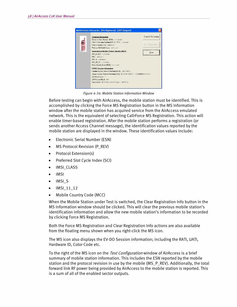
58 | AirAccess C2K User Manual
Figure 4-34: Mobile Station Information Window
Before testing can begin with AirAccess, the mobile station must be identified. This is accomplished by clicking the Force MS Registration button in the MS Information window after the mobile station has acquired service from the AirAccess emulated network. This is the equivalent of selecting Call>Force MS Registration. This action will enable timer-based registration. After the mobile station performs a registration (or sends another Access Channel message), the identification values reported by the mobile station are displayed in the window. These identification values include:
• Electronic Serial Number (ESN)
• MS Protocol Revision (P_REV)
• Protocol Extension(s)
• Preferred Slot Cycle Index (SCI)
• IMSI_CLASS
• IMSI
• IMSI_S
• IMSI_11_12
• Mobile Country Code (MCC)
When the Mobile Station under Test is switched, the Clear Registration Info button in the MS Information window should be clicked. This will clear the previous mobile station’s identification information and allow the new mobile station’s information to be recorded by clicking Force MS Registration.
Both the Force MS Registration and Clear Registration Info actions are also available from the floating menu shown when you right-click the MS icon.
The MS icon also displays the EV-DO Session information; including the RATI, UATI, Hardware ID, Color Code etc.
To the right of the MS icon on the Test Configuration window of AirAccess is a brief summary of mobile station information. This includes the ESN reported by the mobile station and the protocol revision in use by the mobile (MS_P_REV). Additionally, the total forward link RF power being provided by AirAccess to the mobile station is reported. This is a sum of all of the enabled sector outputs.

Chapter Four: Advanced Features | 59
4.4. Modifying Network Topology
The AirAccess Test Configuration window allows you to control the topology of the emulated network. This includes modifying the number of BTSs/sectors and BSCs being emulated.
4.4.1. Adding BTSs
BTSs can be added to a BSC within AirAccess if:
• A call is not currently active on AirAccess
• Additional BTS resources are available
Available BTS resources depend on the current BSC configuration. If only one BSC is enabled, AirAccess has resources to provide up to six BTSs for the active BSC when the TAS5200 is used for RF conversion; or up to three BTSs when the SR3452 V2 internal RF option is used. If two BSCs are enabled, AirAccess can provide up to three BTSs on each of the BSCs.
To add a BTS to a BSC, right-click the BSC where the BTS is desired. From the floating menu that appears, select Add BTS. Alternatively, choose Network>Add Network Element>BTS. This will cause a BTS to become active in the Test Configuration window.
The added BTS will be configured with a set of default values. These values can be changed via the Configure BTS dialog (see Section 4.3.1). The initial power level of the new BTS will be set to the lowest value given the current configuration. This will result in a change in the total RF power level at the mobile station.
4.4.2. Removing a BTS
To remove a BTS from a BSC, right-click on the BSC where the BTS is to be removed. From the floating menu, select Remove BTS. Alternatively, you can select Network>Delete 1X BTS. This menu option is not be available if a call is active on AirAccess. Selecting Remove causes the most recently added BTS on the selected BSC to be removed. This results in a change in the total RF power level at the mobile station.
4.4.3. Switching between BSC/AN Modes
Adding or removing BSCs and ANs within AirAccess results in an operating mode change that requires reconfiguration of the AirAccess instruments. If AirAccess is connected to the instruments when the BSC/AN topology is changed, AirAccess automatically reconfigures the instruments. If AirAccess is not connected to the instruments at the time of the change, the instruments are correctly configured when the next instrument connection is performed (refer to Section 3.6 for details).
60 | AirAccess C2K User Manual
AirAccess stores separate sets of parameters (within the same configuration file) for each of the BSC/AN modes. For example, changes to a BTS made in one BSC mode do not affect the second BSC mode. Each time the operator switches between different modes, AirAccess reloads the appropriate set of parameters.
NOTE: In the current release of AirAccess, the PN Offsets of BTSs are set to fixed values when in two BSC mode.
The AirAccess 1xPLUS system provides the following configurations:
• Dual IS-2000 BSCs w/3 BTS – In this configuration, AirAccess 1xPLUS provides two IS-2000 BSCs, each capable of providing up to 3 BTSs. Each of the BSCs also supports IS-95A/B and J-STD-008 protocols.
• Dual IS-2000 BSCs w/3 BTS, Dual PDSN – In this configuration, AirAccess 1xPLUS provides two IS-2000 BSCs, each capable of providing up to 3 BTSs. Each of the BSCs also supports IS-95A/B and J-STD-008 protocols. A separate PDSN is implemented for each BSC, thus enabling inter-PDSN handoffs.
• Single IS-2000 BSC w/6 BTS – In this configuration, AirAccess 1xPLUS provides a single IS-2000 BSC, which provides up to 6 BTSs. This BSC also supports IS-95A/B and J-STD-008 protocols.
• IS-2000 BSC and IS-856 AN – In this configuration, AirAccess 1xPLUS provides one IS-2000 BSC and one 1xEV-DO sector. The IS-2000 BSC provides up to 3 BTSs, and also supports IS-95A/B and J-STD-008 protocols. The 1xEV-DO sector is sector generated by the SR3462.
• IS-2000 BSC and IS-856 AN, Dual PDSN – In this configuration, AirAccess 1xPLUS provides one IS-2000 BSC and one 1xEV-DO sector. The IS-2000 BSC provides up to 3 BTSs, and also supports IS-95A/B and J-STD-008 protocols. The 1xEV-DO sector is generated by the SR3462. A separate PDSN is emulated for the BSC and the AN, enabling inter-PDSN handoff testing.
• Single AN w/ 2 BTS – In this configuration, AirAccess 1xPLUS provides two 1xEV-DO sectors. The 1xEV-DO sectors are independent sectors generated by the SR3462.
• Single AN w/ 1 BTS – In this configuration, AirAccess 1xPLUS provides one 1xEV-DO sector. The 1xEV-DO sector is independent sector generated by the SR3462.
• TIA-856-B AN – In this configuration, AirAccess 1xPLUS provides one 1xEV-DO sector. The 1xEV-DO sector provides two carriers and is independent sector generated by the SR3462.
• IS-2000 BSC and TIA-856-B AN – In this configuration, AirAccess 1xPLUS provides one IS-2000 BSC and one 1xEV-DO RevB sector. The IS-2000 BSC provides up to three BTSs, and also supports IS-95A/B and J-STD-008 protocols. The 1xEV-DO sector generated by SR3462 supports two carrier EV-DO RevB protocols.
• IS-2000 BSC and TIA-856-B AN, Dual PDSN – In this configuration, AirAccess 1xPLUS provides one IS-2000 BSC and one 1xEV-DO RevB sector. The IS-2000 BSC provides up to three BTSs, and also supports IS-95A/B and J-STD-008 protocols. The 1xEV-DO sector generated by SR3462 supports two carrier EV-DO RevB protocols. A separate PDSN is emulated for the BSC and the AN, enabling inter-PDSN handoff testing.
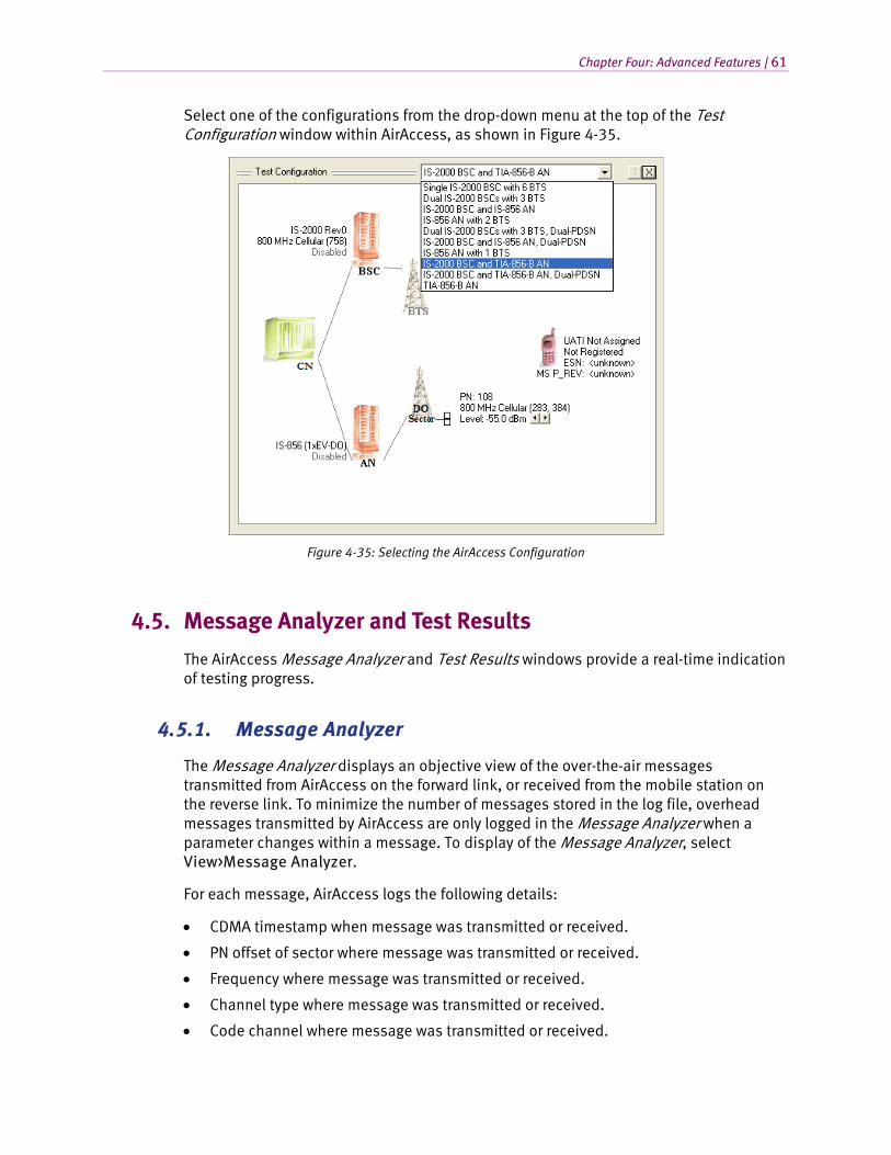
Chapter Four: Advanced Features | 61
Select one of the configurations from the drop-down menu at the top of the Test Configuration window within AirAccess, as shown in Figure 4-35.
Figure 4-35: Selecting the AirAccess Configuration
4.5. Message Analyzer and Test Results
The AirAccess Message Analyzer and Test Results windows provide a real-time indication of testing progress.
4.5.1. Message Analyzer
The Message Analyzer displays an objective view of the over-the-air messages transmitted from AirAccess on the forward link, or received from the mobile station on the reverse link. To minimize the number of messages stored in the log file, overhead messages transmitted by AirAccess are only logged in the Message Analyzer when a parameter changes within a message. To display of the Message Analyzer, select View>Message Analyzer.
For each message, AirAccess logs the following details:
• CDMA timestamp when message was transmitted or received.
• PN offset of sector where message was transmitted or received.
• Frequency where message was transmitted or received.
• Channel type where message was transmitted or received.
• Code channel where message was transmitted or received.
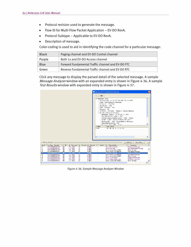
62 | AirAccess C2K User Manual
• Protocol revision used to generate the message.
• Flow ID for Multi-Flow Packet Application – EV-DO RevA.
• Protocol Subtype – Applicable to EV-DO RevA.
• Description of message.
Color-coding is used to aid in identifying the code channel for a particular message:
Black Paging channel and EV-DO Control channel
Purple Both 1x and EV-DO Access channel
Blue Forward Fundamental Traffic channel and EV-DO FTC
Green Reverse Fundamental Traffic channel and EV-DO RTC
Click any message to display the parsed detail of the selected message. A sample Message Analyzer window with an expanded entry is shown in Figure 4-36. A sample Test Results window with expanded entry is shown in Figure 4-37.
Figure 4-36: Sample Message Analyzer Window
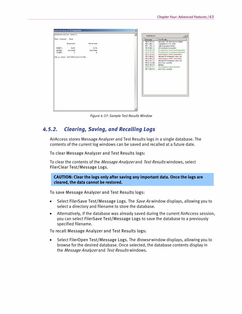
Chapter Four: Advanced Features | 63
Figure 4-37: Sample Test Results Window
4.5.2. Clearing, Saving, and Recalling Logs
AirAccess stores Message Analyzer and Test Results logs in a single database. The contents of the current log windows can be saved and recalled at a future date.
To clear Message Analyzer and Test Results logs:
To clear the contents of the Message Analyzer and Test Results windows, select File>Clear Test/Message Logs.
CAUTION: Clear the logs only after saving any important data. Once the logs are cleared, the data cannot be restored.
To save Message Analyzer and Test Results logs:
• Select File>Save Test/Message Logs. The Save As window displays, allowing you to select a directory and filename to store the database.
• Alternatively, if the database was already saved during the current AirAccess session, you can select File>Save Test/Message Logs to save the database to a previously specified filename.
To recall Message Analyzer and Test Results logs:
• Select File>Open Test/Message Logs. The Browse window displays, allowing you to browse for the desired database. Once selected, the database contents display in the Message Analyzer and Test Results windows.
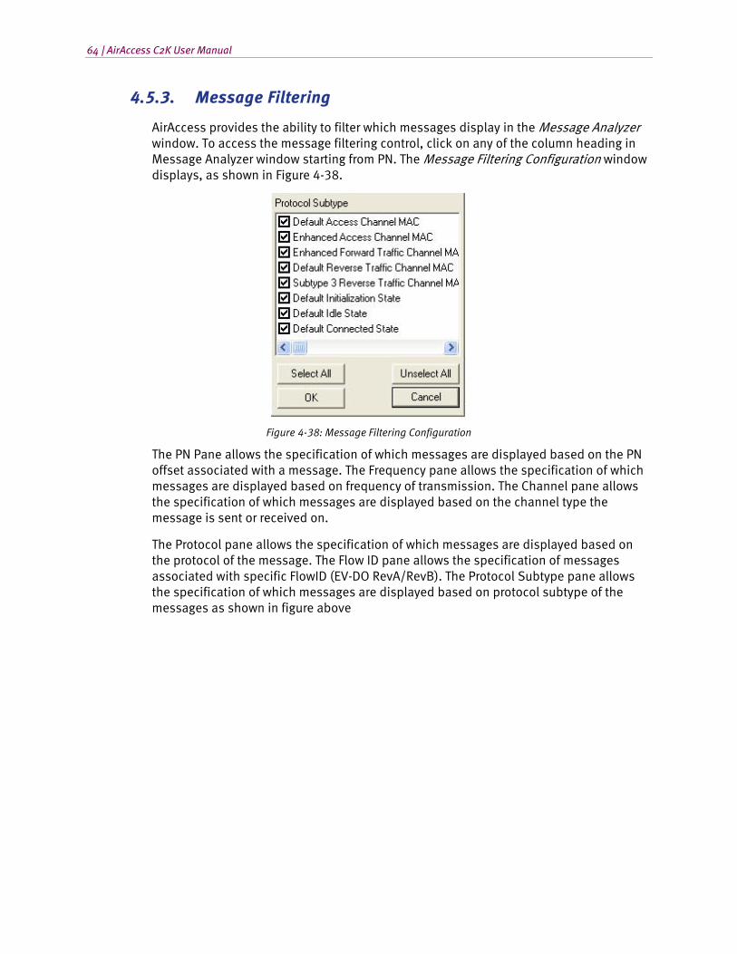
64 | AirAccess C2K User Manual
4.5.3. Message Filtering
AirAccess provides the ability to filter which messages display in the Message Analyzer window. To access the message filtering control, click on any of the column heading in Message Analyzer window starting from PN. The Message Filtering Configuration window displays, as shown in Figure 4-38.
Figure 4-38: Message Filtering Configuration
The PN Pane allows the specification of which messages are displayed based on the PN offset associated with a message. The Frequency pane allows the specification of which messages are displayed based on frequency of transmission. The Channel pane allows the specification of which messages are displayed based on the channel type the message is sent or received on.
The Protocol pane allows the specification of which messages are displayed based on the protocol of the message. The Flow ID pane allows the specification of messages associated with specific FlowID (EV-DO RevA/RevB). The Protocol Subtype pane allows the specification of which messages are displayed based on protocol subtype of the messages as shown in figure above
Chapter Four: Advanced Features | 65
4.6. Authentication
Authentication is the process by which the base station confirms the identity of the mobile station. The authentication process is successful when the base station and mobile station possess identical sets of Shared Secret Data (SSD). The base station may request authentication during MS registration, call origination or call termination, or at any time using the Unique Challenge-Response procedure.
AirAccess can be used to test the following authentication procedures:
• SSD Update procedure
• Authentication on MS registration, call origination and call termination (AUTH = 01)
• Unique Challenge-Response procedure
4.6.1. Setting the A-key
The A-key is a 64-bit number programmed into each mobile. The A-key is used to calculate the Shared Secret Data. In an actual CDMA system, the base station retrieves the A-key from the Home Location Register / Authentication Center (HLR/AC), and then calculates its SSD.
To enter the A-key value to be used by AirAccess C2K:
1. Start call processing (Call>Start Call Processing).
2. Register the mobile to obtain its ESN (Call>Force MS Registration).
3. Open the Configure CN window and select the MSC/IWF Properties tab.
4. Enter the desired A-key value, and then press Enter.
NOTE: Whenever an A-key value is entered, the A-key checksum is calculated and displayed beneath the A-key value. The A-key checksum may be needed to program the A-key value into the mobile station.
5. Click OK button to close the Configure CN window.
When a new A-key value is entered, the Shared Secret Data fields (SSD_A, SSD_B) are reset to zero. The SSD_A and SSD_B fields can be viewed using the Configure CN window.
66 | AirAccess C2K User Manual
4.6.2. Performing an SSD Update Procedure
When the A-key value is entered, the SSD fields (SSD_A, SSD_B) are reset to 0. The base station can request that the mobile regenerate the SSD fields using the SSD Update procedure. In the SSD Update procedure, the base station and mobile must successfully calculate the same results from the generated SSD. If successful, the new SSD fields will be stored and used for subsequent authentication procedures.
To perform the SSD Update procedure using AirAccess:
Set the same A-key value in AirAccess and the mobile station being tested. See “Setting the A-key”, above, for instructions for setting the A-key used by AirAccess. The procedure for programming the A-key into the mobile station is device-specific (unless a diagnostic/provisioning tool such as the Spirent Universal Diagnostic Monitor (UDM) is used).
Start the SSD Update procedure by selecting Test>SSD Update from the application menu.
AirAccess performs the SSD Update procedure and displays the result in the Test Results window. If the SSD Update procedure completes successfully, the text displayed is green. If the procedure is unsuccessful, the text is red.
Double-click the SSD Update test result to view the test details:
• SSD Update Result
• Test Status: Pass
• SSD_A_NEW = 0x9ab39108dfed5954
• SSD_B_NEW = 0x2a1cbd5448d0c156
• RANDSSD = 0x00000000000000
• RANDBS = 0x0733E396
• AUTHBS = 0x02F5A
The SSD Update test details window displays the new SSD field values to be used by AirAccess and the mobile station, as well as other pertinent fields from the messages that were exchanged during the SSD Update procedure.
If the SSD Update procedure fails, the Test Status line displays the reason for the failure.
Test Status Explanation
Fail - BS Challenge Timeout
The mobile station failed to respond to the SSD Update Message with a Base Station Challenge Order within 30 seconds.
Fail - SSD Update Response Order Timeout
The mobile station failed to respond to the Base Station Challenge Confirmation Order with an SSD Update Confirmation Order (success) or SSD Update Rejection Order (failure) within 30 seconds.
Fail An SSD Update Rejection Order was received from the mobile station. This indicates that the AUTHBS value calculated by the mobile did not match the value sent by the base station in the Base Station Challenge Confirmation Order.
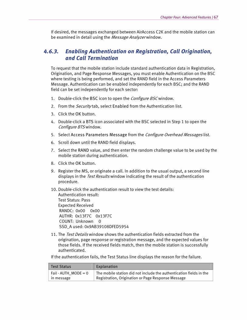
Chapter Four: Advanced Features | 67
If desired, the messages exchanged between AirAccess C2K and the mobile station can be examined in detail using the Message Analyzer window.
4.6.3. Enabling Authentication on Registration, Call Origination, and Call Termination
To request that the mobile station include standard authentication data in Registration, Origination, and Page Response Messages, you must enable Authentication on the BSC where testing is being performed, and set the RAND field in the Access Parameters Message. Authentication can be enabled independently for each BSC; and the RAND field can be set independently for each sector:
1. Double-click the BSC icon to open the Configure BSC window.
2. From the Security tab, select Enabled from the Authentication list.
3. Click the OK button.
4. Double-click a BTS icon associated with the BSC selected in Step 1 to open the Configure BTS window.
5. Select Access Parameters Message from the Configure Overhead Messages list.
6. Scroll down until the RAND field displays.
7. Select the RAND value, and then enter the random challenge value to be used by the mobile station during authentication.
8. Click the OK button.
9. Register the MS, or originate a call. In addition to the usual output, a second line displays in the Test Results window indicating the result of the authentication procedure.
10. Double-click the authentication result to view the test details: Authentication result: Test Status: Pass Expected Received RANDC: 0x00 0x00 AUTHR: 0x13F7C 0x13F7C COUNT: Unknown 0 SSD_A used: 0x9AB39108DFED5954
11. The Test Details window shows the authentication fields extracted from the origination, page response or registration message, and the expected values for those fields. If the received fields match, then the mobile station is successfully authenticated.
If the authentication fails, the Test Status line displays the reason for the failure.
Test Status Explanation
Fail - AUTH_MODE = 0 in message
The mobile station did not include the authentication fields in the Registration, Origination or Page Response Message
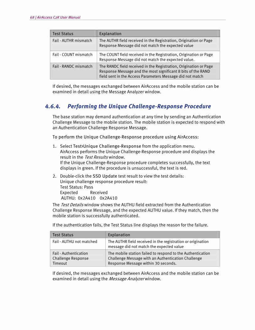
68 | AirAccess C2K User Manual
Test Status Explanation
Fail - AUTHR mismatch The AUTHR field received in the Registration, Origination or Page Response Message did not match the expected value
Fail - COUNT mismatch The COUNT field received in the Registration, Origination or Page Response Message did not match the expected value.
Fail - RANDC mismatch The RANDC field received in the Registration, Origination or Page Response Message and the most significant 8 bits of the RAND field sent in the Access Parameters Message did not match
If desired, the messages exchanged between AirAccess and the mobile station can be examined in detail using the Message Analyzer window.
4.6.4. Performing the Unique Challenge-Response Procedure
The base station may demand authentication at any time by sending an Authentication Challenge Message to the mobile station. The mobile station is expected to respond with an Authentication Challenge Response Message.
To perform the Unique Challenge-Response procedure using AirAccess:
1. Select Test>Unique Challenge-Response from the application menu. AirAccess performs the Unique Challenge-Response procedure and displays the result in the Test Results window. If the Unique Challenge-Response procedure completes successfully, the text displays in green. If the procedure is unsuccessful, the text is red.
2. Double-click the SSD Update test result to view the test details: Unique challenge response procedure result: Test Status: Pass Expected Received AUTHU: 0x2A410 0x2A410
The Test Details window shows the AUTHU field extracted from the Authentication Challenge Response Message, and the expected AUTHU value. If they match, then the mobile station is successfully authenticated.
If the authentication fails, the Test Status line displays the reason for the failure.
Test Status Explanation
Fail - AUTHU not matched The AUTHR field received in the registration or origination message did not match the expected value
Fail - Authentication Challenge Response Timeout
The mobile station failed to respond to the Authentication Challenge Message with an Authentication Challenge Response Message within 30 seconds.
If desired, the messages exchanged between AirAccess and the mobile station can be examined in detail using the Message Analyzer window.
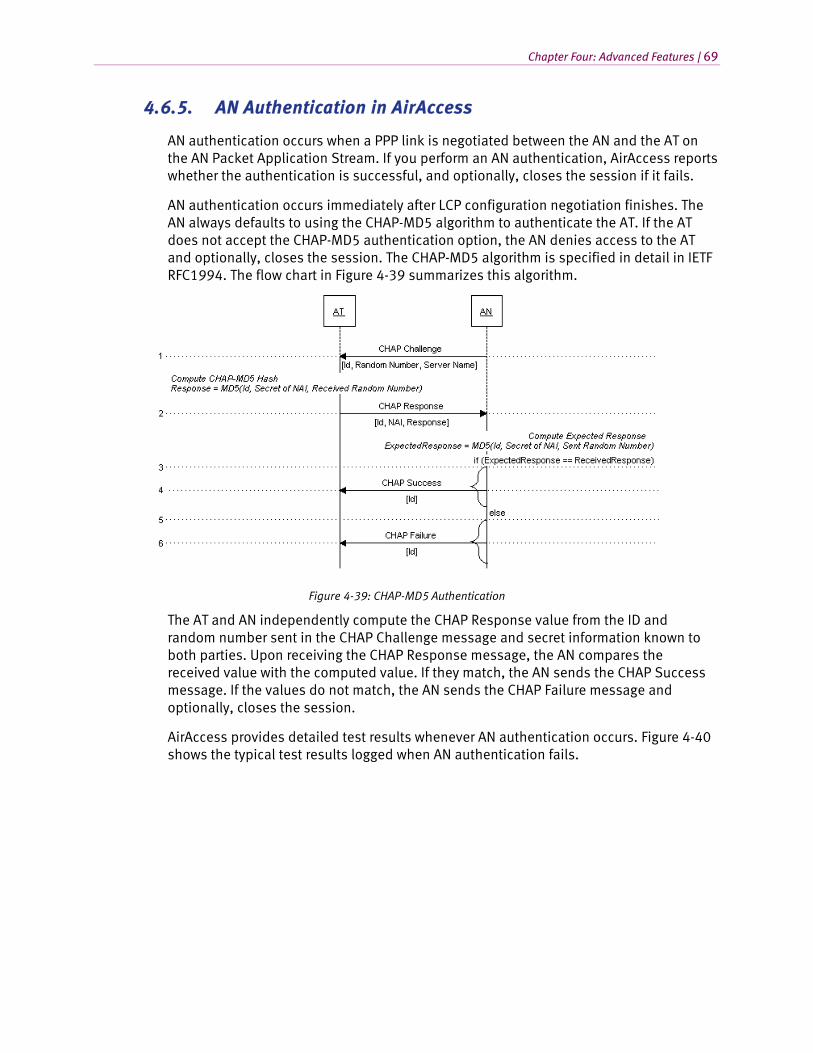
Chapter Four: Advanced Features | 69
4.6.5. AN Authentication in AirAccess
AN authentication occurs when a PPP link is negotiated between the AN and the AT on the AN Packet Application Stream. If you perform an AN authentication, AirAccess reports whether the authentication is successful, and optionally, closes the session if it fails.
AN authentication occurs immediately after LCP configuration negotiation finishes. The AN always defaults to using the CHAP-MD5 algorithm to authenticate the AT. If the AT does not accept the CHAP-MD5 authentication option, the AN denies access to the AT and optionally, closes the session. The CHAP-MD5 algorithm is specified in detail in IETF RFC1994. The flow chart in Figure 4-39 summarizes this algorithm.
Figure 4-39: CHAP-MD5 Authentication
The AT and AN independently compute the CHAP Response value from the ID and random number sent in the CHAP Challenge message and secret information known to both parties. Upon receiving the CHAP Response message, the AN compares the received value with the computed value. If they match, the AN sends the CHAP Success message. If the values do not match, the AN sends the CHAP Failure message and optionally, closes the session.
AirAccess provides detailed test results whenever AN authentication occurs. Figure 4-40 shows the typical test results logged when AN authentication fails.
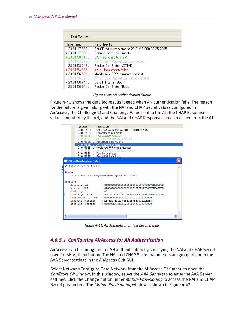
70 | AirAccess C2K User Manual
Figure 4-40: AN Authentication Failure
Figure 4-41 shows the detailed results logged when AN authentication fails. The reason for the failure is given along with the NAI and CHAP Secret values configured in AirAccess, the Challenge ID and Challenge Value sent to the AT, the CHAP Response value computed by the AN, and the NAI and CHAP Response values received from the AT.
Figure 4-41: AN Authentication Test Result Details
4.6.5.1 Configuring AirAccess for AN Authentication
AirAccess can be configured for AN authentication by specifying the NAI and CHAP Secret used for AN Authentication. The NAI and CHAP Secret parameters are grouped under the AAA Server settings in the AirAccess C2K GUI.
Select Network>Configure Core Network from the AirAccess C2K menu to open the Configure CN window. In this window, select the AAA Server tab to enter the AAA Server settings. Click the Change button under Mobile Provisioning to access the NAI and CHAP Secret parameters. The Mobile Provisioning window is shown in Figure 4-42.
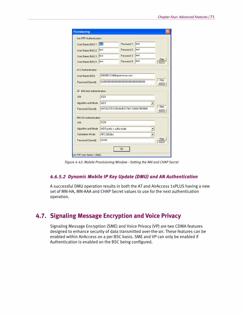
Chapter Four: Advanced Features | 71
Figure 4-42: Mobile Provisioning Window –Setting the NAI and CHAP Secret
4.6.5.2 Dynamic Mobile IP Key Update (DMU) and AN Authentication
A successful DMU operation results in both the AT and AirAccess 1xPLUS having a new set of MN-HA, MN-AAA and CHAP Secret values to use for the next authentication operation.
4.7. Signaling Message Encryption and Voice Privacy
Signaling Message Encryption (SME) and Voice Privacy (VP) are two CDMA features designed to enhance security of data transmitted over-the-air. These features can be enabled within AirAccess on a per BSC basis. SME and VP can only be enabled if Authentication is enabled on the BSC being configured.
72 | AirAccess C2K User Manual
4.7.1. Enabling SME
When SME is enabled, AirAccess will encrypt certain data fields in messages transmitted on the Forward Traffic Channel. The fields that are encrypted are defined by the CDMA specifications.
To enable this encryption:
1. Double-click on a BSC icon to open the Configure BSC window.
2. From the Security tab, select Enabled from the Authentication list.
3. From the Security tab, select Basic or Enhanced from the Encryption list.
4. Click the OK button to close the window.
When AirAccess sends or receives a message with encrypted fields, both the raw encrypted and unencrypted data displays in the Detailed Message View of the Message Analyzer window.
NOTE: Enhanced encryption is not available if the protocol in use is TSB-74 or J-STD-008.
4.7.2. Enabling VP
VP can be enabled both before and during a voice conversation.
To enable VP:
1. Double-click on a BSC icon to open the Configure BSC window.
2. From the Security tab, select Enabled from the Authentication list.
3. From the Security tab, select Enabled from the Voice Privacy list.
4. Click the OK button.
If VP is enable prior to beginning a call, AirAccess will look at the Privacy Mode (PM) bit sent by the Mobile Station under Test in the Origination Message or Page Response Message. If this bit is set, AirAccess will begin the transition process to VP by sending a Long Code Transition Request Order on the Forward Traffic Channel.
If VP is enabled or disabled during a call, AirAccess immediately begins the transition process by sending a Long Code Transition Request Order on the Forward Traffic Channel.
Note that the Voice Privacy Request from MS setting under the Security tab controls the behavior of AirAccess when the mobile initiates a request to transition to using the private long code mask. When this setting is set to “Accept”, AirAccess allows the transition to a private long code mask to take place.
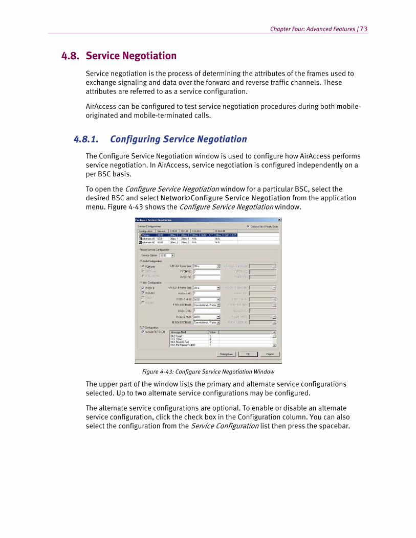
Chapter Four: Advanced Features | 73
4.8. Service Negotiation
Service negotiation is the process of determining the attributes of the frames used to exchange signaling and data over the forward and reverse traffic channels. These attributes are referred to as a service configuration.
AirAccess can be configured to test service negotiation procedures during both mobile-originated and mobile-terminated calls.
4.8.1. Configuring Service Negotiation
The Configure Service Negotiation window is used to configure how AirAccess performs service negotiation. In AirAccess, service negotiation is configured independently on a per BSC basis.
To open the Configure Service Negotiation window for a particular BSC, select the desired BSC and select Network>Configure Service Negotiation from the application menu. Figure 4-43 shows the Configure Service Negotiation window.
Figure 4-43: Configure Service Negotiation Window
The upper part of the window lists the primary and alternate service configurations selected. Up to two alternate service configurations may be configured.
The alternate service configurations are optional. To enable or disable an alternate service configuration, click the check box in the Configuration column. You can also select the configuration from the Service Configuration list then press the spacebar.
74 | AirAccess C2K User Manual
4.8.2. Editing Service Configuration Attributes
NOTE: The Service Options available for selection is a function of the protocol in use and which AirAccess optional software modules are installed.
The controls in the lower part of the window are used to edit the attributes of each service configuration. To edit the attributes in a service configuration, first select the configuration in the Service Configurations list. Then use the individual controls to select the desired attributes for the service configuration.
NOTE: In the current version of AirAccess, variable frame sizes and the Dedicated Common Control Channels (F/R-DCCH) are not supported. The controls for configuring these attributes are disabled.
4.8.3. Strict Priority Order
The Enforce Strict Priority Order parameter controls how the emulator responds to a service configuration proposed by the mobile station. If Strict Priority Order is disabled, the emulator accepts any of the service configurations on the list. When enabled, the emulator rejects an alternate service configuration initially proposed by the mobile station, and instead tries to negotiate the primary service configuration. If the primary service configuration is rejected, the emulator then attempts to negotiate the first alternate service configuration. The second alternate service configuration is accepted only after the others have been proposed and rejected.
4.8.4. RLP BLOB
When SO33 (HSPD) is the service option configured in the selected configuration, the bottom part of the window provides the ability to configure RLP BLOB parameters.
4.8.5. Viewing Service Negotiation Results
When a call is successfully established, the Test Results Details window displays the actual service configuration negotiated during call setup, as in this example:
• MS-terminated call established
• Service Configuration:
• Service Option = SO3
• F-FCH RC = 1
• R-FCH RC = 1
• F-FCH MUX Option = 0x01
• R-FCH MUX Option = 0x01
To open the Test Results Details window, double-click MS-terminated call established or MS-originated call established in the Test Results window.
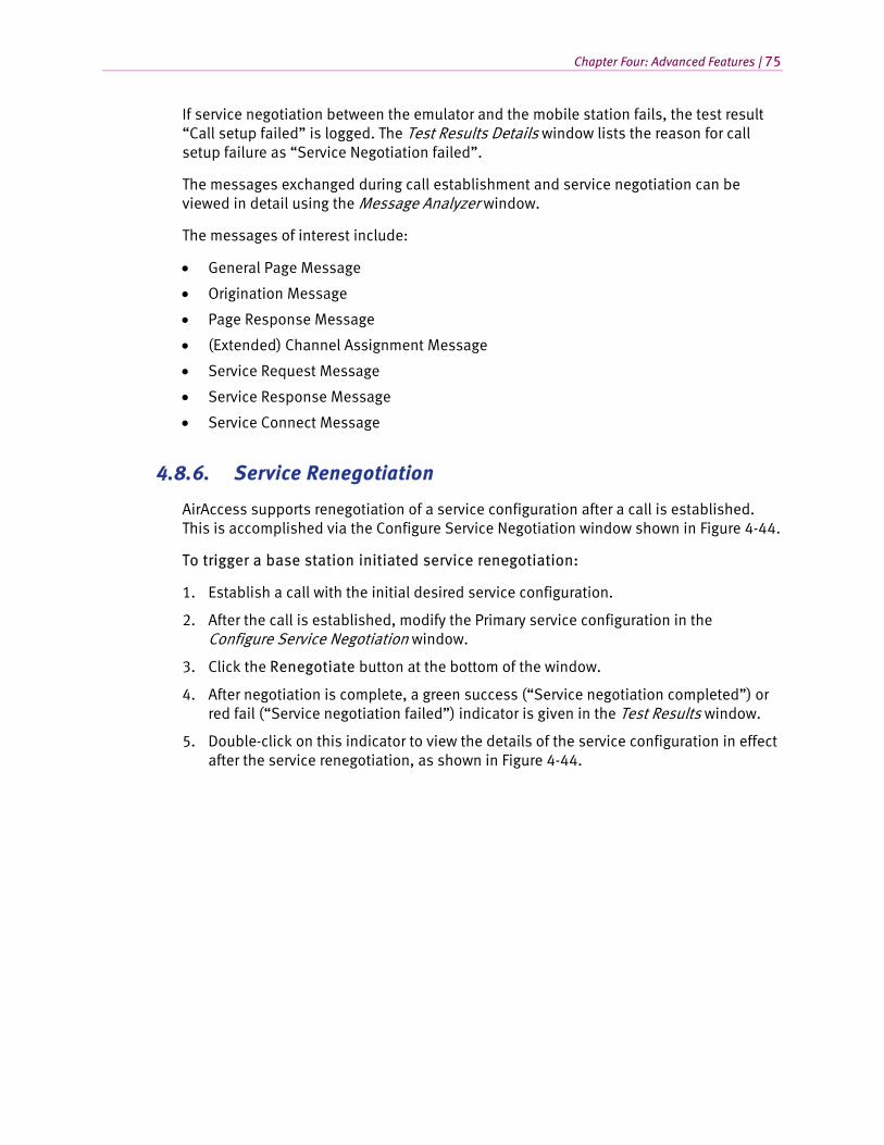
Chapter Four: Advanced Features | 75
If service negotiation between the emulator and the mobile station fails, the test result “Call setup failed” is logged. The Test Results Details window lists the reason for call setup failure as “Service Negotiation failed”.
The messages exchanged during call establishment and service negotiation can be viewed in detail using the Message Analyzer window.
The messages of interest include:
• General Page Message
• Origination Message
• Page Response Message
• (Extended) Channel Assignment Message
• Service Request Message
• Service Response Message
• Service Connect Message
4.8.6. Service Renegotiation
AirAccess supports renegotiation of a service configuration after a call is established. This is accomplished via the Configure Service Negotiation window shown in Figure 4-44.
To trigger a base station initiated service renegotiation:
1. Establish a call with the initial desired service configuration.
2. After the call is established, modify the Primary service configuration in the Configure Service Negotiation window.
3. Click the Renegotiate button at the bottom of the window.
4. After negotiation is complete, a green success (“Service negotiation completed”) or red fail (“Service negotiation failed”) indicator is given in the Test Results window.
5. Double-click on this indicator to view the details of the service configuration in effect after the service renegotiation, as shown in Figure 4-44.
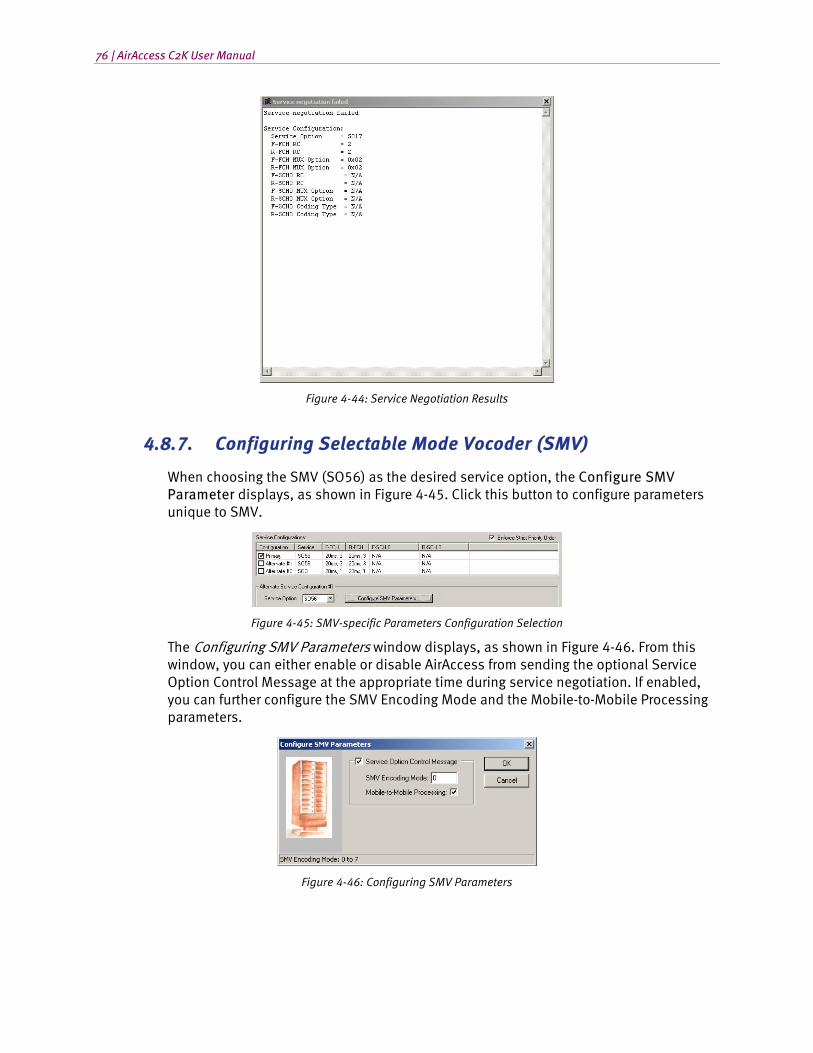
76 | AirAccess C2K User Manual
Figure 4-44: Service Negotiation Results
4.8.7. Configuring Selectable Mode Vocoder (SMV)
When choosing the SMV (SO56) as the desired service option, the Configure SMV Parameter displays, as shown in Figure 4-45. Click this button to configure parameters unique to SMV.
Figure 4-45: SMV-specific Parameters Configuration Selection
The Configuring SMV Parameters window displays, as shown in Figure 4-46. From this window, you can either enable or disable AirAccess from sending the optional Service Option Control Message at the appropriate time during service negotiation. If enabled, you can further configure the SMV Encoding Mode and the Mobile-to-Mobile Processing parameters.
Figure 4-46: Configuring SMV Parameters

Chapter Four: Advanced Features | 77
4.9. Message Insertion
AirAccess enables you to send individual CDMA messages over the paging (f-csch) or traffic (f-dsch) channels. The Message Insertion window allows you to select, customize, and send individual CDMA messages. The table below lists the available CDMA messages.
CDMA Message Paging (f-csch) Traffic (f-dsch)
Alert With Information Message No Yes
Candidate Frequency Search Control Message No Yes
Candidate Frequency Search Request Message No Yes
Data Burst Message Yes Yes
Extended Neighbor List Update Message No Yes
Feature Notification Message Yes No
Flash With Information Message No Yes
In-Traffic System Parameters Message No Yes
Mobile Station Registered Message No Yes
Neighbor List Update Message No Yes
Order Message Yes Yes
Power Control Parameters Message No Yes
Power Control Message No Yes
Retrieve Parameters Message No Yes
Send Burst DTMF Message No Yes
Service Redirection Message Yes Yes
Set Parameters Message No Yes
Status Request Message Yes Yes
EV-DO Message Traffic (f-dsch)
ResetReport Message Yes
UnicastReverseRateLimit Message Yes
4.9.1. Insert Messages on the Paging Channel
To insert CDMA messages on the forward paging channel:
1. Start call processing by selecting Call>Start Call Processing.
2. Register the mobile station by selecting Call>Force MS Registration. The mobile station must be registered before inserting messages on the paging channel, so that the correct mobile address fields can be included in the messages.
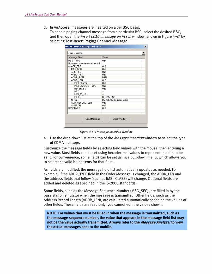
78 | AirAccess C2K User Manual
3. In AirAccess, messages are inserted on a per BSC basis. To send a paging channel message from a particular BSC, select the desired BSC, and then open the Insert CDMA message on f-csch window, shown in Figure 4-47 by selecting Test>Insert Paging Channel Message.
Figure 4-47: Message Insertion Window
4. Use the drop-down list at the top of the Message Insertion window to select the type of CDMA message.
Customize the message fields by selecting field values with the mouse, then entering a new value. Most fields can be set using hexadecimal values to represent the bits to be sent. For convenience, some fields can be set using a pull-down menu, which allows you to select the valid bit patterns for that field.
As fields are modified, the message field list automatically updates as needed. For example, if the ADDR_TYPE field in the Order Message is changed, the ADDR_LEN and the address fields that follow (such as IMSI_CLASS) will change. Optional fields are added and deleted as specified in the IS-2000 standards.
Some fields, such as the Message Sequence Number (MSG_SEQ), are filled in by the base station emulator when the message is transmitted. Other fields, such as the Address Record Length (ADDR_LEN), are calculated automatically based on the values of other fields. These fields are read-only; you cannot edit the values shown.
NOTE: For values that must be filled in when the message is transmitted, such as the message sequence number, the value that appears in the message field list may not be the value actually transmitted. Always refer to the Message Analyzer to view the actual messages sent to the mobile.
Chapter Four: Advanced Features | 79
Some messages contain one or more records. Each record repeats a set of fields. The number of records included in the message often depends on the value of a field earlier in the message. The message field list automatically displays the correct number of records. Records are indented to make them easier to recognize. The first field in a record is marked with an arrow.
Sometimes, the number of records does not depend on another message field, but instead on the length of the message itself. In these cases, the message field list contains a field labeled “Number of occurrences of record”. Enter the number of records desired, and the message field list expands or contracts in response.
Click the Send Message button to insert the message into the paging channels associated with the selected BSC.
Click the Close Window button to close the message insertion window when you are finished sending messages.
4.9.2. Insert Messages on the Traffic Channel
To insert CDMA messages on the forward traffic channel:
1. Start call processing by selecting Call>Start Call Processing. Register the mobile by selecting Call>Force MS Registration, and initiate a mobile-originated or mobile-terminated call.
2. In AirAccess, messages are inserted on a per BSC/AN basis. To send a forward traffic channel message from a particular BSC (or AN), click the desired node to highlight it, and then open the Message Insertion window by selecting Test>Insert Traffic Channel Message.
3. In the Message Insertion window, you can select, customize, and send CDMA messages, as described in Section 4.9.1: Insert Messages on the Paging Channel.
4.9.3. Position Location (IS-801.1) Message Insertion
IS-801.1 Position Location messages transported using the Data Burst Message can be inserted on the Paging Channel or Traffic Channel using AirAccess.
To insert an IS-801.1 formatted message:
1. Follow the procedure in Section 4.9.1 of this manual (for a Paging Channel Message) or Section 4.9.2 of this manual (for a Traffic Channel Message) to open the appropriate Message Insertion window.
2. Using the pull-down list at the top of the window and select Data Burst Message.
3. Select Position Determination from the BURST_TYPE list, as shown in Figure 4-48.
4. The IS-801.1-specific fields display and can now be populated.
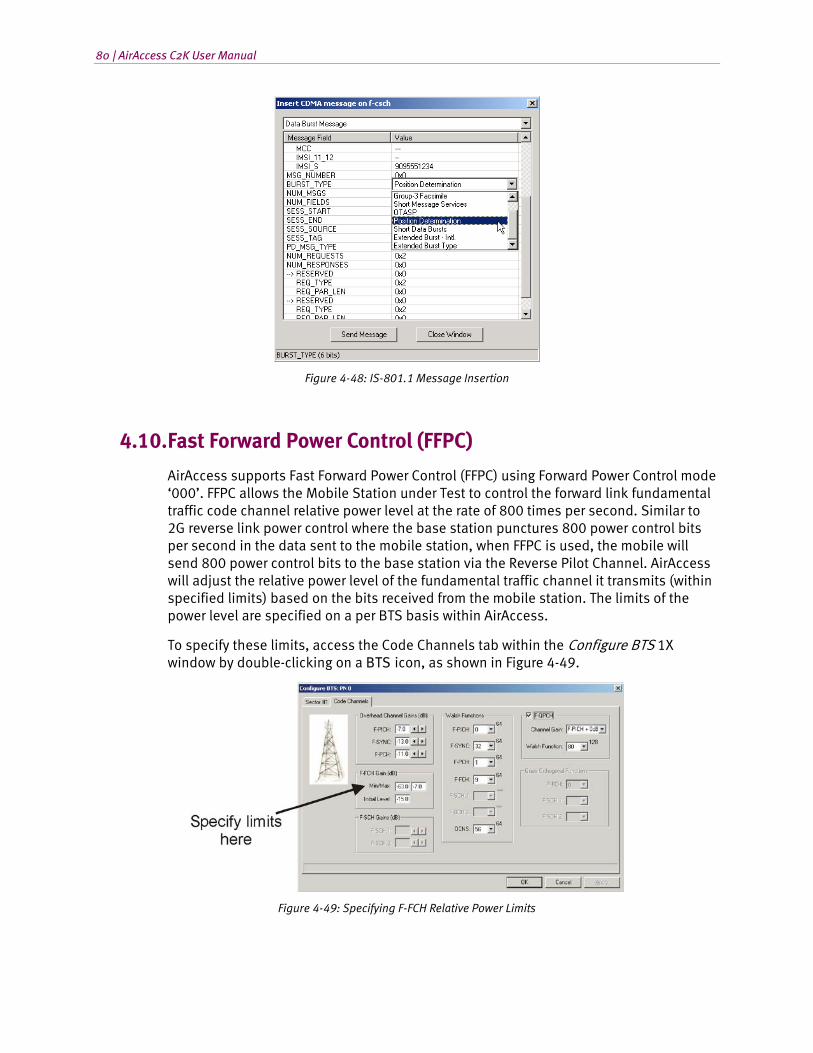
80 | AirAccess C2K User Manual
Figure 4-48: IS-801.1 Message Insertion
4.10. Fast Forward Power Control (FFPC)
AirAccess supports Fast Forward Power Control (FFPC) using Forward Power Control mode ‘000’. FFPC allows the Mobile Station under Test to control the forward link fundamental traffic code channel relative power level at the rate of 800 times per second. Similar to 2G reverse link power control where the base station punctures 800 power control bits per second in the data sent to the mobile station, when FFPC is used, the mobile will send 800 power control bits to the base station via the Reverse Pilot Channel. AirAccess will adjust the relative power level of the fundamental traffic channel it transmits (within specified limits) based on the bits received from the mobile station. The limits of the power level are specified on a per BTS basis within AirAccess.
To specify these limits, access the Code Channels tab within the Configure BTS 1X window by double-clicking on a BTS icon, as shown in Figure 4-49.
Figure 4-49: Specifying F-FCH Relative Power Limits
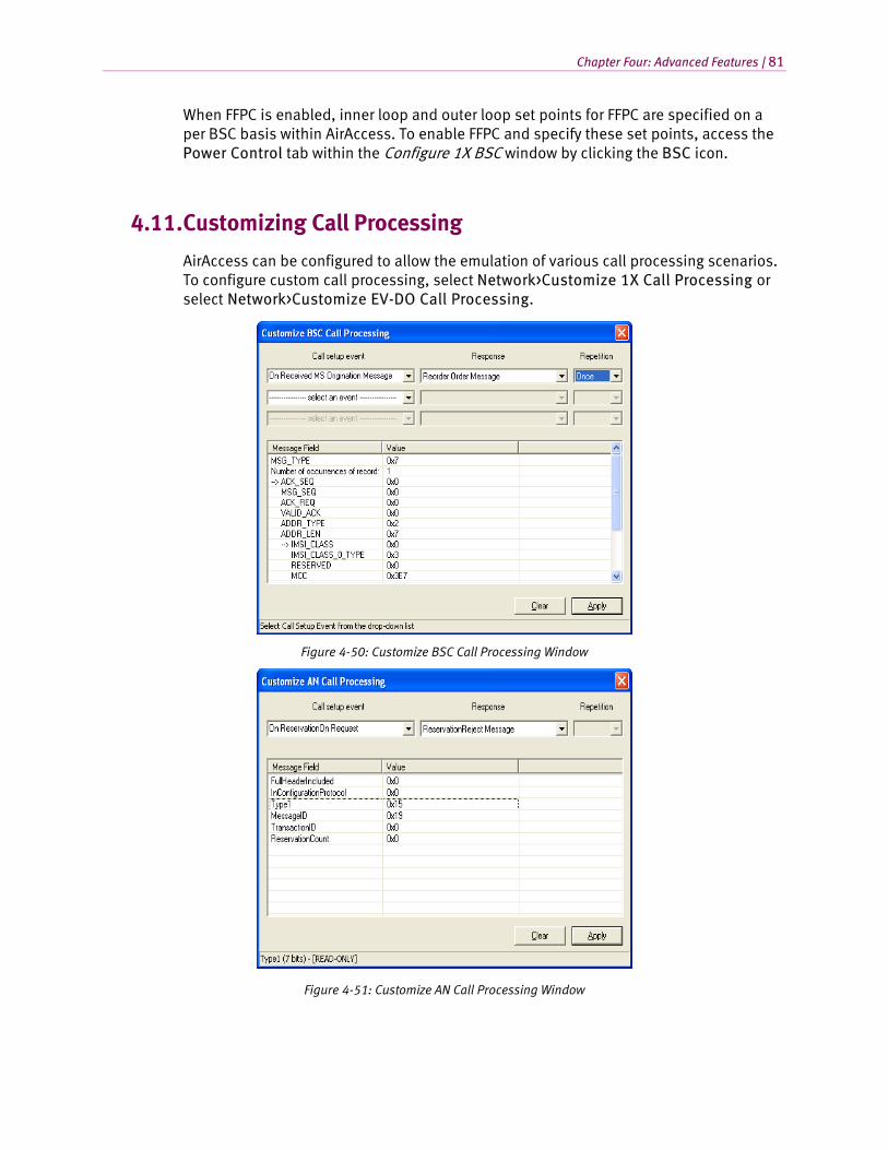
Chapter Four: Advanced Features | 81
When FFPC is enabled, inner loop and outer loop set points for FFPC are specified on a per BSC basis within AirAccess. To enable FFPC and specify these set points, access the Power Control tab within the Configure 1X BSC window by clicking the BSC icon.
4.11. Customizing Call Processing
AirAccess can be configured to allow the emulation of various call processing scenarios. To configure custom call processing, select Network>Customize 1X Call Processing or select Network>Customize EV-DO Call Processing.
Figure 4-50: Customize BSC Call Processing Window
Figure 4-51: Customize AN Call Processing Window
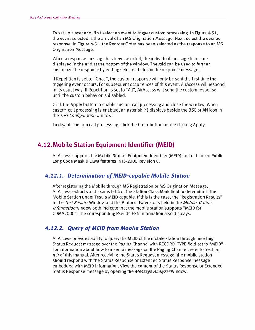
82 | AirAccess C2K User Manual
To set up a scenario, first select an event to trigger custom processing. In Figure 4-51, the event selected is the arrival of an MS Origination Message. Next, select the desired response. In Figure 4-51, the Reorder Order has been selected as the response to an MS Origination Message.
When a response message has been selected, the individual message fields are displayed in the grid at the bottom of the window. The grid can be used to further customize the response by editing selected fields in the response message.
If Repetition is set to “Once”, the custom response will only be sent the first time the triggering event occurs. For subsequent occurrences of this event, AirAccess will respond in its usual way. If Repetition is set to “All”, AirAccess will send the custom response until the custom behavior is disabled.
Click the Apply button to enable custom call processing and close the window. When custom call processing is enabled, an asterisk (*) displays beside the BSC or AN icon in the Test Configuration window.
To disable custom call processing, click the Clear button before clicking Apply.
4.12. Mobile Station Equipment Identifier (MEID)
AirAccess supports the Mobile Station Equipment Identifier (MEID) and enhanced Public Long Code Mask (PLCM) features in IS-2000 Revision 0.
4.12.1. Determination of MEID-capable Mobile Station
After registering the Mobile through MS Registration or MS Origination Message, AirAccess extracts and exams bit 4 of the Station Class Mark field to determine if the Mobile Station under Test is MEID capable. If this is the case, the “Registration Results” in the Test Results Window and the Protocol Extensions field in the Mobile Station Information window both indicate that the mobile station supports “MEID for CDMA2000”. The corresponding Pseudo ESN information also displays.
4.12.2. Query of MEID from Mobile Station
AirAccess provides ability to query the MEID of the mobile station through inserting Status Request message over the Paging Channel with RECORD_TYPE field set to “MEID”. For information about how to insert a message on the Paging Channel, refer to Section 4.9 of this manual. After receiving the Status Request message, the mobile station should respond with the Status Response or Extended Status Response message embedded with MEID information. View the content of the Status Response or Extended Status Response message by opening the Message Analyzer Window.

Chapter Four: Advanced Features | 83
4.12.3. Channel Assignment for MEID-capable Mobile Stations
AirAccess supports “Base Station-specified Public Long Code Mask (PLCM)”. To configure the PLCM, open the Configure BSC window and select the Security tab.
Select the “Base Station-specified PLCM” option and ensure the Mobile Station under Test is MEID-capable. AirAccess then uses the MEID Extended Channel Assignment message instead of the Extended Channel Assignment to assign the FCH to the mobile station.
4.12.4. Hard Handoff for MEID-capable Mobile Stations
When initiating a hard handoff from an IS-2000 base station, you can select the MEID Universal Handoff Direction Message if the registered mobile is MEID-capable. When the MEID Universal Handoff Message is used, and PLCM_TYPE_INCL is set to “1”, AirAccess will automatically set the PLCM_TYPE and the PLCM_39 fields based on the properties configured for the target base station.
If the PLCM_TYPE_INCL field is set to “0”, the target base station continues to use the current PLCM. This selection overrides the PLCM options selected for the target base station.
4.12.5. Over-the-Air Provisioning
AirAccess supports MEID query capability during OTASP/OTAPA operation. When IS-2000 protocol is selected and the Mobile Station under Test is MEID-capable, AirAccess includes the OTASP_P_REV, NUM_CAP_RECORDS, and CAP_RECORD_TYPE fields in the Protocol Capability Request message. The latter two fields are also configured. In response, the mobile station should send the Extended Protocol Capability Response message with MEID information. View the content of this message by opening the Message Analyzer Window.
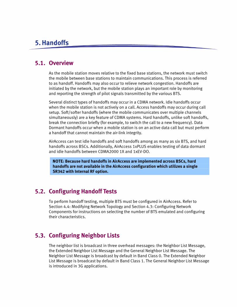
5. Handoffs
5.1. Overview
As the mobile station moves relative to the fixed base stations, the network must switch the mobile between base stations to maintain communications. This process is referred to as handoff. Handoffs may also occur to relieve network congestion. Handoffs are initiated by the network, but the mobile station plays an important role by monitoring and reporting the strength of pilot signals transmitted by the various BTS.
Several distinct types of handoffs may occur in a CDMA network. Idle handoffs occur when the mobile station is not actively on a call. Access handoffs may occur during call setup. Soft/softer handoffs (where the mobile communicates over multiple channels simultaneously) are a key feature of CDMA systems. Hard handoffs, unlike soft handoffs, break the connection briefly (for example, to switch the call to a new frequency). Data Dormant handoffs occur when a mobile station is on an active data call but must perform a handoff that cannot maintain the air-link integrity.
AirAccess can test idle handoffs and soft handoffs among as many as six BTS, and hard handoffs across BSCs. Additionally, AirAccess 1xPLUS enables testing of data dormant and idle handoffs between CDMA2000 1X and 1xEV-DO.
NOTE: Because hard handoffs in AirAccess are implemented across BSCs, hard handoffs are not available in the AirAccess configuration which utilizes a single SR342 with Internal RF option.
5.2. Configuring Handoff Tests
To perform handoff testing, multiple BTS must be configured in AirAccess. Refer to Section 4.4: Modifying Network Topology and Section 4.3: Configuring Network Components for instructions on selecting the number of BTS emulated and configuring their characteristics.
5.3. Configuring Neighbor Lists
The neighbor list is broadcast in three overhead messages: the Neighbor List Message, the Extended Neighbor List Message and the General Neighbor List Message. The Neighbor List Message is broadcast by default in Band Class 0. The Extended Neighbor List Message is broadcast by default in Band Class 1. The General Neighbor List Message is introduced in 3G applications.
Chapter Five: Handoffs | 85
To set up a neighbor list, edit these overhead messages using the Configure 1X BTS window. Refer to Section 4.3: Configuring Network Components for details.
For each message, the procedure is the same:
Enter the number of pilots that should display in the list by changing the “Number of occurrences of record” value.
In each sub-record, set the NGHBR_PN field to the PN Offset of one of the neighboring sectors.
5.4. Adjusting Sector Gains
The movement of the mobile station relative to the BTSs is simulated by adjusting the transmit power for each sector. This is most easily accomplished using the Gain controls on the Test Configuration window, shown in Figure 4-2. Alternatively, the transmit power can be adjusted by opening the Configure 1X BTS window and entering a new value.
The individual sector gains (Level) and the total RF transmit power (Total) display in the Test Configuration window.
5.5. Idle Handoffs
Idle handoffs occur when the mobile station locks onto a stronger pilot signal from a neighboring base station. To determine whether idle handoff has occurred; register the mobile or originate a call, then observe which PN offset the mobile uses using the AirAccess Message Analyzer window; or use a diagnostic tool such as Spirent’s Universal Diagnostic Monitor (UDM) to monitor the mobile during the test.
The following example illustrates using AirAccess to trigger an idle handoff.
1. Create a network topology with two or more active BTS.
2. Add the other pilots to the Neighbor List Message broadcast by each BTS. This is not required for handoff, but affects how quickly the mobile locates additional pilots.
3. For each BTS, enable Zone-based Registration by setting the TOTAL_ZONES field in the System Parameters Message to 1. Set the REG_ZONE field to a unique value for each BTS.
4. Set the sector gain for one sector 6 dB higher than the others. Set the relative level for each pilot to the same level (-7.0 dB).
5. Start call processing by selecting Call>Start Call Processing. The mobile should perform a zone-based registration. NOTE: Observe the PN offset logged for the Registration Message. This should correspond to the pilot for the strongest sector.
6. Decrease the gain of the strongest sector by 6 dB. Increase the gain of another sector by the same amount.
86 | AirAccess C2K User Manual
7. The mobile should perform another zone-based registration. The PN offset for the Registration Message should correspond to the new strongest pilot. This indicates that the mobile station has locked onto the stronger pilot, completing an idle handoff.
5.6. Soft Handoffs
During soft handoff, the mobile station communications with multiple base stations simultaneously.
The following example illustrates a simple two-way soft handoff:
1. Create a network topology with two or more active BTS.
2. Add the other pilots to the Neighbor List Message broadcast by each BTS. This is not required for handoff, but affects how quickly the mobile locates additional pilots.
3. Set the sector gain for one sector 12 dB higher than the others. Set the relative level for each pilot to the same level (-7.0 dB).
4. Start call processing by selecting Call>Start Call Processing. Register the mobile by selecting Call>Force MS Registration. Initiate a MS-terminated call by selecting Call>Initiate MS-Terminated Call.
5. When the call is established, AirAccess logs the current state of the active and candidate sector sets. Double-click the “Active List updated” line in the Test Results log to view the active and candidate sector sets. The log should display something similar to the following: Active and Candidate Sets: Active Set: PN Offset Strength Keep 0 15 1
Candidate Set: PN Offset Strength Keep
Currently the mobile is communicating with a single base station sector (PN Offset = 0 in the example above). The other pilot signals are too weak, so the candidate list is empty. Note that the Test Configuration window indicates the active sector with a small green marker. The markers for the remaining sectors are gray, indicating that they are transmitting pilot signals, but are not considered candidates for handoff.
6. Use the spin control to increase the gain of one of the other sectors until it is level with the active sector. As you increase the gain, you should see the marker for that sector change from gray to yellow. At the same time, AirAccess will log a Pilot Strength Measurement Message in the message log and another “Active List updated” line in the test results log.
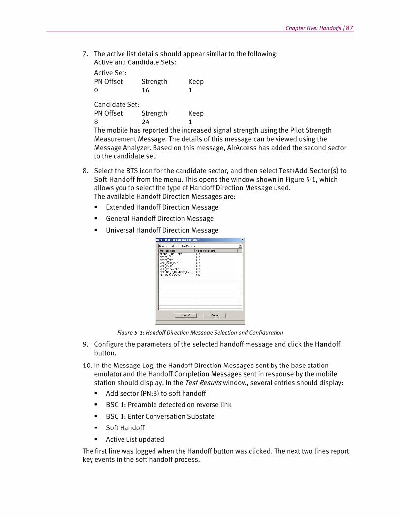
Chapter Five: Handoffs | 87
7. The active list details should appear similar to the following: Active and Candidate Sets:
Active Set: PN Offset Strength Keep 0 16 1
Candidate Set: PN Offset Strength Keep 8 24 1 The mobile has reported the increased signal strength using the Pilot Strength Measurement Message. The details of this message can be viewed using the Message Analyzer. Based on this message, AirAccess has added the second sector to the candidate set.
8. Select the BTS icon for the candidate sector, and then select Test>Add Sector(s) to Soft Handoff from the menu. This opens the window shown in Figure 5-1, which allows you to select the type of Handoff Direction Message used. The available Handoff Direction Messages are:
Extended Handoff Direction Message
General Handoff Direction Message
Universal Handoff Direction Message
Figure 5-1: Handoff Direction Message Selection and Configuration
9. Configure the parameters of the selected handoff message and click the Handoff button.
10. In the Message Log, the Handoff Direction Messages sent by the base station emulator and the Handoff Completion Messages sent in response by the mobile station should display. In the Test Results window, several entries should display:
Add sector (PN:8) to soft handoff
BSC 1: Preamble detected on reverse link
BSC 1: Enter Conversation Substate
Soft Handoff
Active List updated
The first line was logged when the Handoff button was clicked. The next two lines report key events in the soft handoff process.

88 | AirAccess C2K User Manual
11. The “Soft Handoff” line indicates whether the process completed successfully (green) or failed (red).
When the handoff completes successfully, the active list is updated. Double-click on the line reading “Active List updated” to view the updated active and candidate sets:
Active and Candidate Sets:
Active Set: PN Offset Strength Keep 0 16 1 8 24 1 Candidate Set: PN Offset Strength Keep
Now both sectors are members of the active set, meaning that the mobile station is simultaneously communicating with both. The simultaneous connection is also indicated on the Test Configuration window (both sectors have green markers).
12. Decrease the gain of the first sector. After you decrease the gain, the marker should change from green to red. This is in response to another Pilot Strength Measurement Message from the mobile.
Active and Candidate Sets:
Active Set: PN Offset Strength Keep 0 39 0 8 15 1
Candidate Set: PN Offset Strength Keep
NOTE: The mobile now reports that the signal from one of the sectors is below the level desired (Keep = 0).
13. Remove this sector from soft handoff by highlighting its BTS icon, then selecting Test>Remove Sector(s) from Soft Handoff from the menu. AirAccess opens a window, as shown in Figure 5-1, allowing you to select the type of Handoff Direction Message used. Select and configure the handoff message, and then click the Handoff button to send the message.
14. The Message Analyzer displays the CDMA messages sent and received, the Test Results window displays the results of the handoff process. The Test Configuration window displays the updated state of the active and candidate sets.
If the process completed successfully, the mobile should be communicating with only a single BTS.
Chapter Five: Handoffs | 89
5.6.1. Reduced Active Set Soft Handoffs
While on a high-speed packet data call with supplemental channels active, AirAccess supports a reduced active set soft handoff. This is a soft handoff where only the fundamental channels are placed into soft handoff, but the supplemental channels are not placed into soft handoff.
The process to perform a reduced active set soft handoff is similar to the process used for a regular soft handoff as described above. The variations to the steps above are:
Instead of initiating a mobile-terminated call, create a high-speed packet data call with supplemental channels active. Refer to Section 6.3.4 of this manual for information on establishing this data call.
When ready to initiate the handoff, select the BTS icon for the candidate sector, and then select Test>Add FCH to Soft Handoff
After the handoff, the added sector that only is communicating over the fundamental channels (i.e. the supplemental channels were not added on the new sector) will be indicated by a box next to the BTS tower that is half green, half white.
5.7. Hard Handoffs
NOTE: Because hard handoffs in AirAccess are implemented across BSCs, hard handoffs are not available in the AirAccess configuration which utilizes a single SR342 with Internal RF module.
During hard handoff, the mobile station communications with only one base station at a time. Hard handoffs are a break-before-make connection.
In AirAccess, hard handoffs are performed between two BTSs on different BSCs.
The following example illustrates a simple hard handoff between frequencies.
1. Create a network topology with two BSCs and one active BTS per BSC.
2. Confirm that the other pilots are not in the Neighbor List Message broadcast by each BTS.
3. Set the sector gain for one sector 12 dB higher than the other. Set the relative level for each pilot to the same level (-7.0 dB).
4. Start call processing by selecting Call>Start Call Processing, register the mobile by selecting Call>Force MS Registration, and initiate a MS-terminated call by selecting Call>Initiate MS-Terminated Call.
5. Verify the call is established on the sector with the higher gain setting. This can be verified by observing the small green marker next to the active sector.
6. Use the spin control to increase the gain of the other sector (the “target” sector) until it is level with the active sector.
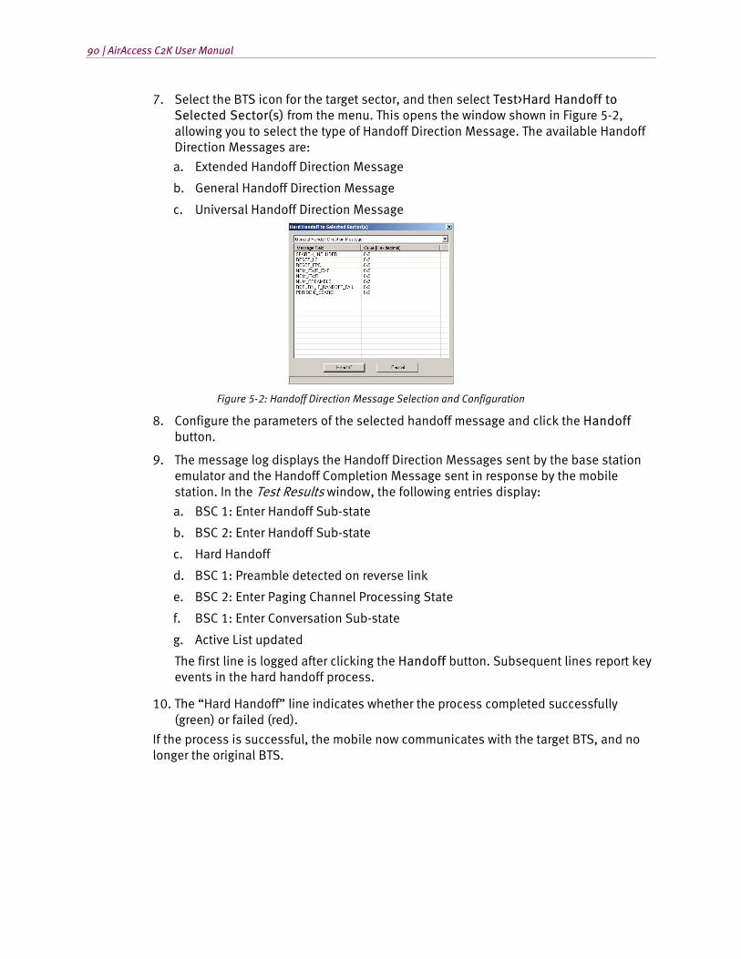
90 | AirAccess C2K User Manual
7. Select the BTS icon for the target sector, and then select Test>Hard Handoff to Selected Sector(s) from the menu. This opens the window shown in Figure 5-2, allowing you to select the type of Handoff Direction Message. The available Handoff Direction Messages are:
a. Extended Handoff Direction Message
b. General Handoff Direction Message
c. Universal Handoff Direction Message
Figure 5-2: Handoff Direction Message Selection and Configuration
8. Configure the parameters of the selected handoff message and click the Handoff button.
9. The message log displays the Handoff Direction Messages sent by the base station emulator and the Handoff Completion Message sent in response by the mobile station. In the Test Results window, the following entries display:
a. BSC 1: Enter Handoff Sub-state
b. BSC 2: Enter Handoff Sub-state
c. Hard Handoff
d. BSC 1: Preamble detected on reverse link
e. BSC 2: Enter Paging Channel Processing State
f. BSC 1: Enter Conversation Sub-state
g. Active List updated
The first line is logged after clicking the Handoff button. Subsequent lines report key events in the hard handoff process.
10. The “Hard Handoff” line indicates whether the process completed successfully (green) or failed (red).
If the process is successful, the mobile now communicates with the target BTS, and no longer the original BTS.
Chapter Five: Handoffs | 91
5.8. Inter-technology Handoff
NOTE: Because Inter-technology dormant data handoffs are between 1xRTT and EV-DO, hard handoffs are not available in the AirAccess configuration that utilizes a single SR342 V2 or dual SR3452 V2 with Internal RF module.
During inter-technology handoff, the mobile station communications with either the BSC or AN. Inter-technology handoffs are a break-before-make connection.
In AirAccess, inter-technology dormant data handoffs are performed between 1xRTT BTS and 1xEV-DO Sector.
The following example illustrates a simple inter-technology handoff between frequencies:
1. Create a network topology with one BSC with one connected BTS and one AN.
2. Disable RF transmission for 1xEV-DO sector by right-clicking DO Sector and selecting Disable RF Transmission.
3. Set the RANHandoff attribute of Stream 2 to 1 by selecting Network>Configure EV-DO Personality. Under the Personality Attribute tab, select Stream 2, as shown in Figure 5-3.
4. Open the Configure Service Negotiation window by selecting Network>Configure 1X Service Negotiation, and select a packet data service option (SO33).
5. Configure parameters for the SO33, as discussed in Section 4.8), and click OK.
6. Start call processing by selecting Call>Start Call Processing.
7. Connect a terminal (TE2M) to the mobile under test. Configure the mobile for a packet data call.
8. Initiate a mobile-originated dial-up connection using the username: test and the password: test.
9. Verify the call is established on the BTS sector. This can be verified by observing the small green marker next to the active sector.
10. Enable 1xEV-DO Sector RF Transmission by right-clicking DO Sector and selecting Enable RF Transmission.
If the process completed successfully, the mobile communicates with the DO Sector, and not the original BTS.
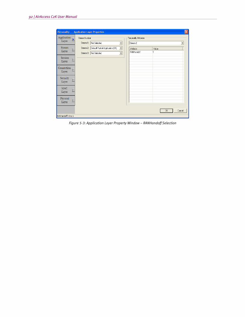
92 | AirAccess C2K User Manual
Figure 5-3: Application Layer Property Window – RANHandoff Selection
6. Data Services Testing
6.1. Overview
This chapter is applicable to AirAccess C2K and AirAccess 1xPLUS.
These optional AirAccess software modules provide asynchronous and packet data service test capabilities:
• AAC2K-HSPD CDMA2000 1X and IS-95 Packet data services
• AAC2K-MIP Mobile IP packet data services
• AAC2K-DMU Dynamic Mobile IP Key Update services
Additionally, the AirAccess 1xPLUS configuration includes the ability to perform 3.1 Mbps forward link / 1.8 Mbps reverse link 1xEV-DO RevA data testing and 6.2 Mbps forward link/3.6 Mbps reverse link 1xEV-DO RevB data testing.
For data services testing, AirAccess emulates the transceiver (BSC/BTS), Mobile Switching Center (MSC), Inter-Working Function (IWF), and Packet Data Serving Node (PDSN). In the case of Mobile IP, AirAccess also emulates a Home Agent (HA), Foreign Agent (FA) and AAA Server.
6.2. Asynchronous Data Services
AirAccess supports SO12 (Asynchronous Data Service). The optional module AAC2K-HSPD is required to test asynchronous data services.
For file upload/download testing, a communications application (HyperTerminal) is used to emulate the land-side terminal equipment (TE2L). For asynchronous dial-up testing, Quick Net Connect (QNC) calls can be established using SO12.
6.2.1. Establishing a Quick Net Connect Call
To establish a dial-up connection using Quick Net Connect (QNC):
1. Open the Configure Service Negotiation window by selecting Network>Configure 1X Service Negotiation, select the S012 service option, then press OK.
2. Start call processing by selecting Call>Start Call Processing.
3. Connect a terminal (TE2M) to the mobile under test. Configure the mobile for a dial-up connection using QNC.
4. Initiate a mobile-originated dial-up connection using the username: qnc and the password: qnc.
94 | AirAccess C2K User Manual
NOTE: The command string to establish a QNC dial-up connection is implementation
dependent; for example, “#777”.
5. Run a packet data application, such as a Web browser or FTP client, on the terminal attached to the mobile (TE2M).
6. The AirAccess System Controller PC runs the Microsoft Internet Information Server (IIS) Web server and FTP server. These servers can be accessed using the IP address of the AirAccess controller (192.168.0.5). Other servers can be accessed if AirAccess is attached to an external LAN via the provided Router
6.2.2. Ending a Quick Net Connect Call
To end an ASYNC Data Call, use the data application that established the call (not the AirAccess software). For example, end a QNC data call by terminating the dial-up connection from the terminal attached to the mobile.
6.3. CDMA2000 1X and IS-95 Packet Data Services
AirAccess supports SO4103 (Packet Data Service: IP, Revision 1), SO15 (14.4 kbps Packet Data Service: IP), SO22 and SO25 (Medium-Speed Packet Data Service) without Supplemental Code Channels, SO33 (144 kbps Packet Data Service) and SO32 (TDSO). The optional module AAC2K-HSPD is required to test packet data services.
6.3.1. Establishing a Packet Data Call
To establish a dial-up connection using a packet data service option:
1. Open the Configure Service Negotiation window (Network>Configure 1X Service Negotiation), then select a packet data service option
2. Configure parameters for the selected service option (see Section 4.8), and then press OK.
3. Start call processing (Call>Start Call Processing).
4. Connect a terminal (TE2M) to the mobile under test. Configure the mobile for a packet data call.
5. Initiate a mobile-originated dial-up connection using the username: test and the password: test.
6. When the call is successfully established, the entry “MS-originated call established” will be recorded in the Test Results log. Subsequent entries in the Test Results log record the process of establishing a data connection between the two applications.
Chapter Six: Data Services Testing | 95
Test Results Log Entry Description
RLP Parameters Update Records the version of the Radio Link Protocol (RLP) used over the air interface and the values of several RLP parameters.
Packet Call State: Active Indicates successful establishment of a PPP connection between the mobile/TE2M and the PDSN.
IP Addr of IWF/PDSN Reports the IP address assigned to the PDSN end of the PPP link.
IP Addr of Mobile Reports the IP address assigned to the mobile end of the PPP link.
RLP Statistics Records a snapshot of RLP statistics for a given BSC
Run a packet data application, such as a Web browser or FTP client, on the terminal attached to the mobile (TE2M).
The AirAccess System Controller PC runs the Microsoft Internet Information Server (IIS) Web server and FTP server. These servers can be accessed using the IP address of the AirAccess controller (192.168.0.5). Other servers can be accessed if AirAccess is attached to an external LAN via the provided Router.
6.3.2. Ending a Packet Data Call
End a packet data call by terminating the dial-up connection from the terminal attached to the mobile.
6.3.3. Testing Active/Dormant State Transitions
Mobile stations and base stations may implement an inactivity timer. The inactivity timer will cause the call to transition to dormant state when packets are not being transferred. In dormant state, the data link over the air interface is closed, but the mobile station and base station maintain an active PPP link. This allows the data link to be quickly reestablished when new data must be transferred.
AirAccess can be used to test the transition to dormant state and reestablishment of the dormant link layer connection. AirAccess implements a programmable inactivity timer to determine when to go to the dormant state.
To test active/dormant state transitions:
1. Establish a packet data call.
2. Let the data application be inactive until the inactivity timer expires. Alternatively, manually end the call using the AirAccess software (Call>End Call). This should result in a transition to dormant state. On its transition to dormant state, AirAccess will record the entry “Packet Call State: Dormant” in the Test Results log.
3. Use the data application to send new packets across the link. This should result in the reestablishment of the data link.
96 | AirAccess C2K User Manual
NOTE: If the mobile fails to keep its end of the PPP link active after entering dormant state, attempts to reestablish the data link will fail. AirAccess implements a dormant time-out to recover from this situation. After 3 minutes of inactivity in the dormant state, AirAccess will terminate its end of the PPP link and enter the Null state. Once the emulator enters the Null state, a new call can be established.
6.3.4. Using Supplemental Channels
To achieve data rates greater than 9.6 or 14.4 kbps, supplemental channels can be used in addition to fundamental channels on the forward and/or reverse links.
Within AirAccess, supplemental channels can be enabled from the Configure Service Negotiation window. To open this window, select Network>Configure 1X Service Negotiation or select Configure Service Negotiation from the right-click menu of the BSC.
Supplemental channels are enabled within the Configure Service Negotiation window by first selecting SO33 as the service option. Once SO33 is selected, forward and reverse supplemental channels can independently be enabled by checking the appropriate boxes within the f/r-dtch Configuration section of the window.
Once a supplemental channel is enabled, additional information about the supplemental channel can be configured. This information includes radio configurations and multiplex options. Each supplemental channel maintains an independent configuration. The selection of a radio configuration defines the available multiplex options as shown in the table below.
Radio Configuration Available Multiplex Options
Forward Link
3 0x03, 0x809, 0x811, 0x821, 0x905, 0x909, 0x911, 0x921
4 0x03, 0x809, 0x811, 0x821, 0x905, 0x909, 0x911, 0x921
Reverse Link
3 0x03, 0x809, 0x811, 0x821, 0x905, 0x909, 0x911, 0x921
The maximum air-link throughput available on either the forward link or reverse link is a function of the selected multiplex options on the fundamental and supplemental channels, as well as the format of RLP3 frames used. Refer to Section 6.3.7 below for information on changing RLP3 frame format types.
When one or more supplemental channels are enabled under the f/r-dtch Configuration section of the window, a Coding option is made available. This coding option provides two selections:
• Convolutional Only
• Convolutional / Turbo
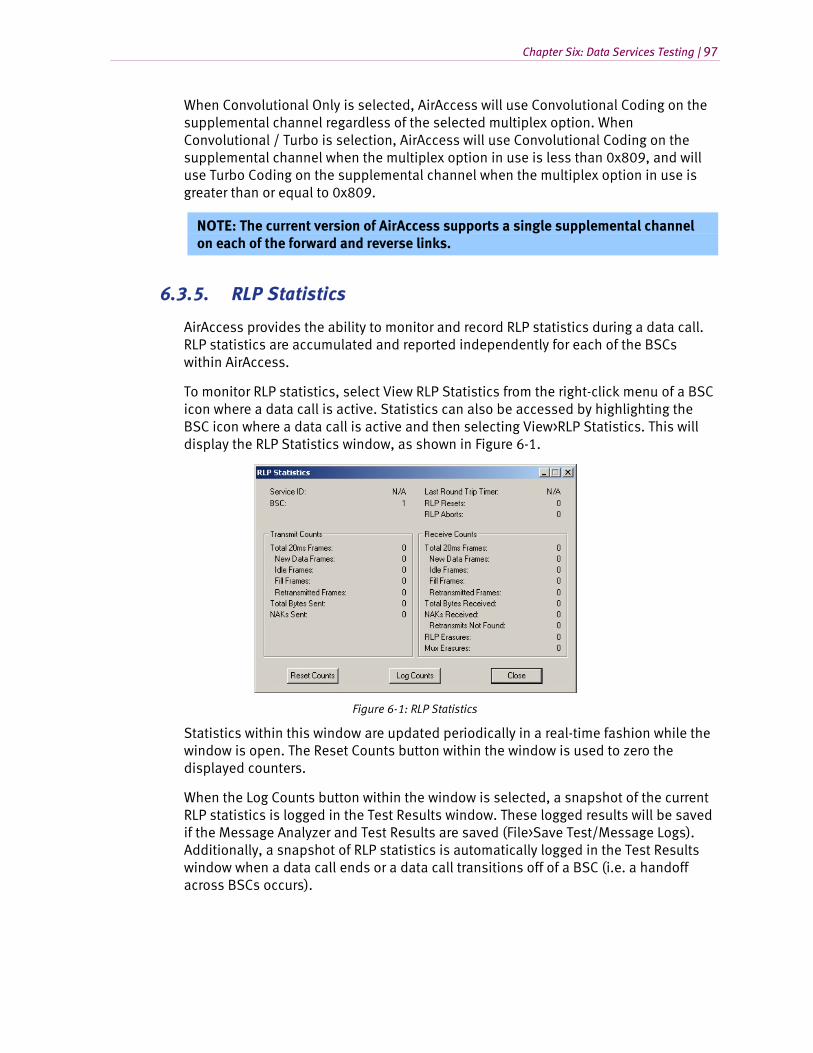
Chapter Six: Data Services Testing | 97
When Convolutional Only is selected, AirAccess will use Convolutional Coding on the supplemental channel regardless of the selected multiplex option. When Convolutional / Turbo is selection, AirAccess will use Convolutional Coding on the supplemental channel when the multiplex option in use is less than 0x809, and will use Turbo Coding on the supplemental channel when the multiplex option in use is greater than or equal to 0x809.
NOTE: The current version of AirAccess supports a single supplemental channel on each of the forward and reverse links.
6.3.5. RLP Statistics
AirAccess provides the ability to monitor and record RLP statistics during a data call. RLP statistics are accumulated and reported independently for each of the BSCs within AirAccess.
To monitor RLP statistics, select View RLP Statistics from the right-click menu of a BSC icon where a data call is active. Statistics can also be accessed by highlighting the BSC icon where a data call is active and then selecting View>RLP Statistics. This will display the RLP Statistics window, as shown in Figure 6-1.
Figure 6-1: RLP Statistics
Statistics within this window are updated periodically in a real-time fashion while the window is open. The Reset Counts button within the window is used to zero the displayed counters.
When the Log Counts button within the window is selected, a snapshot of the current RLP statistics is logged in the Test Results window. These logged results will be saved if the Message Analyzer and Test Results are saved (File>Save Test/Message Logs). Additionally, a snapshot of RLP statistics is automatically logged in the Test Results window when a data call ends or a data call transitions off of a BSC (i.e. a handoff across BSCs occurs).
98 | AirAccess C2K User Manual
The following RLP statistics are monitored and logged:
• Service ID
• Last Round Trip Timer
• RLP Resets
• RLP Aborts
• Transmit Counts
• Total 20ms Frames
• New Data Frames
• Idle Frames
• Fill Frames
• Retransmitted Frames
• Total Bytes Sent
• NAKs Sent
• Receive Counts
• Total 20ms Frames
• New Data Frames
• Idle Frames
• Fill Frames
• Retransmitted Frames
• Total Bytes Received
• NAKs Received
• Retransmits Not Found
• RLP Erasures
• Mux Erasures
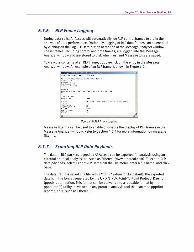
Chapter Six: Data Services Testing | 99
6.3.6. RLP Frame Logging
During data calls, AirAccess will automatically log RLP control frames to aid in the analysis of data performance. Optionally, logging of RLP data frames can be enabled by clicking on the Log RLP Data button at the top of the Message Analyzer window. These frames, including control and data frames, are logged into the Message Analyzer window and are stored to disk when Test and Message logs are saved.
To view the contents of an RLP frame, double-click on the entry in the Message Analyzer window. An example of an RLP frame is shown in Figure 6-2.
Figure 6-2: RLP Frame Logging
Message filtering can be used to enable or disable the display of RLP frames in the Message Analyzer window. Refer to Section 4.5.4 for more information on message filtering.
6.3.7. Exporting RLP Data Payloads
The data in RLP packets logged by AirAccess can be exported for analysis using an external protocol analysis tool such as Ethereal (www.ethereal.com). To export RLP data payloads, select Export RLP Data from the File menu, enter a file name, and click Save.
The data traffic is saved in a file with a “.dmp” extension by default. The exported data is in the format generated by the UNIX/LINUX Point-To-Point Protocol Daemon (pppd) report option. This format can be converted to a readable format by the pppdump(8) utility, or viewed in any protocol analysis tool that can read pppd(8) report output, such as Ethereal.

100 | AirAccess C2K User Manual
6.3.8. Selectable RLP3 Frame Types
AirAccess supports multiple RLP3 frame types on high-speed packet data (SO33) calls. Three options are available:
1. Segmented Data Frames
2. Unsegmented Data Frames – No Format B Frames
3. Unsegmented Data Frames – Format B Frames Allowed
The frame type in use can be selected from the RLP tab of the Configure BSC window. Refer to Section 4.3.2 of this manual for information on changing BSC parameters.
NOTE: These data rates specified in the below sections might not be realized due to rate limitations of the data connection to the Mobile Station under Test.
6.3.8.1 Segmented Data Frames
When Segmented Data Frames is selected, AirAccess utilizes the following RLP frame formats for transferring all data:
• FCH and SCH using Mux Option 0x03: Format A – Segmented Data Frames
• SCH using Mux Options > 0x03: Format D Data Frames
• Unsegmented Data Frames – No Format B Frames
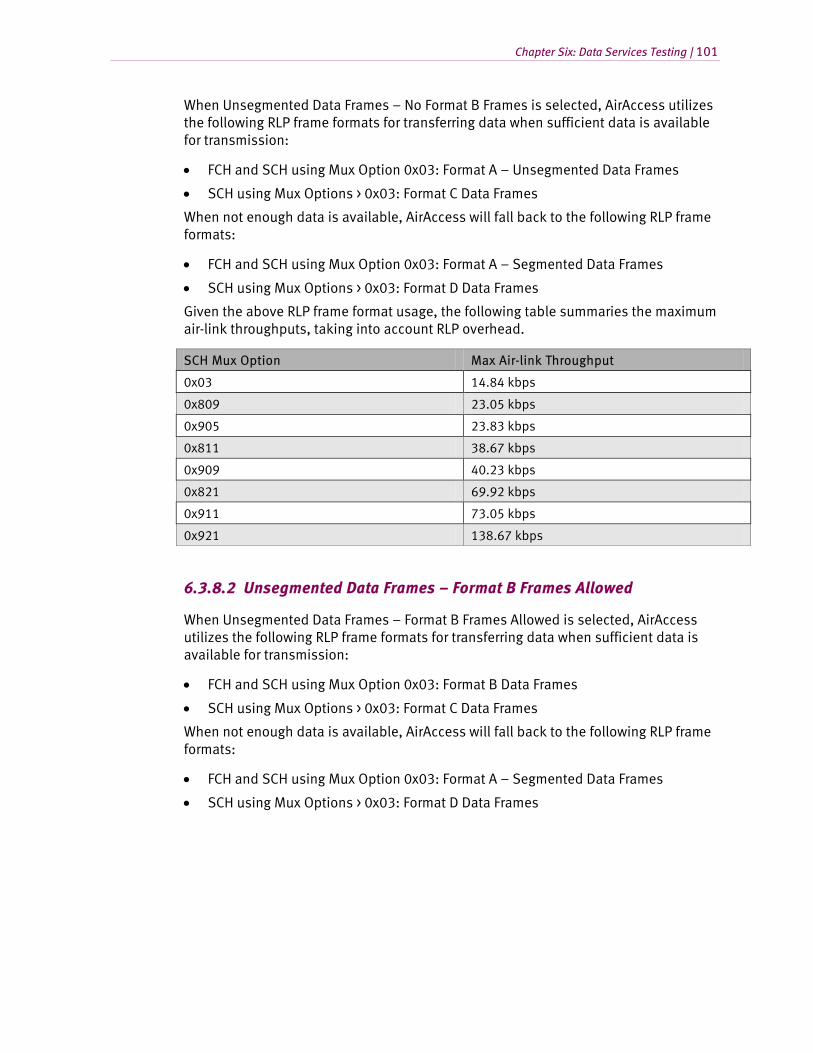
Chapter Six: Data Services Testing | 101
When Unsegmented Data Frames – No Format B Frames is selected, AirAccess utilizes the following RLP frame formats for transferring data when sufficient data is available for transmission:
• FCH and SCH using Mux Option 0x03: Format A – Unsegmented Data Frames
• SCH using Mux Options > 0x03: Format C Data Frames
When not enough data is available, AirAccess will fall back to the following RLP frame formats:
• FCH and SCH using Mux Option 0x03: Format A – Segmented Data Frames
• SCH using Mux Options > 0x03: Format D Data Frames
Given the above RLP frame format usage, the following table summaries the maximum air-link throughputs, taking into account RLP overhead.
SCH Mux Option Max Air-link Throughput
0x03 14.84 kbps
0x809 23.05 kbps
0x905 23.83 kbps
0x811 38.67 kbps
0x909 40.23 kbps
0x821 69.92 kbps
0x911 73.05 kbps
0x921 138.67 kbps
6.3.8.2 Unsegmented Data Frames – Format B Frames Allowed
When Unsegmented Data Frames – Format B Frames Allowed is selected, AirAccess utilizes the following RLP frame formats for transferring data when sufficient data is available for transmission:
• FCH and SCH using Mux Option 0x03: Format B Data Frames
• SCH using Mux Options > 0x03: Format C Data Frames
When not enough data is available, AirAccess will fall back to the following RLP frame formats:
• FCH and SCH using Mux Option 0x03: Format A – Segmented Data Frames
• SCH using Mux Options > 0x03: Format D Data Frames
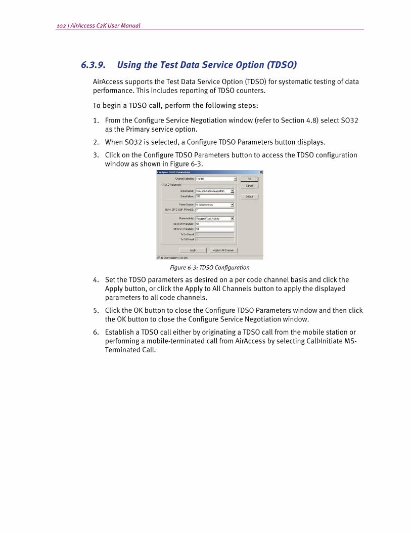
102 | AirAccess C2K User Manual
6.3.9. Using the Test Data Service Option (TDSO)
AirAccess supports the Test Data Service Option (TDSO) for systematic testing of data performance. This includes reporting of TDSO counters.
To begin a TDSO call, perform the following steps:
1. From the Configure Service Negotiation window (refer to Section 4.8) select SO32 as the Primary service option.
2. When SO32 is selected, a Configure TDSO Parameters button displays.
3. Click on the Configure TDSO Parameters button to access the TDSO configuration window as shown in Figure 6-3.
Figure 6-3: TDSO Configuration
4. Set the TDSO parameters as desired on a per code channel basis and click the Apply button, or click the Apply to All Channels button to apply the displayed parameters to all code channels.
5. Click the OK button to close the Configure TDSO Parameters window and then click the OK button to close the Configure Service Negotiation window.
6. Establish a TDSO call either by originating a TDSO call from the mobile station or performing a mobile-terminated call from AirAccess by selecting Call>Initiate MS-Terminated Call.
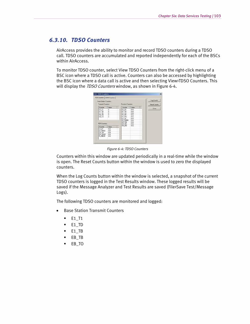
Chapter Six: Data Services Testing | 103
6.3.10. TDSO Counters
AirAccess provides the ability to monitor and record TDSO counters during a TDSO call. TDSO counters are accumulated and reported independently for each of the BSCs within AirAccess.
To monitor TDSO counter, select View TDSO Counters from the right-click menu of a BSC icon where a TDSO call is active. Counters can also be accessed by highlighting the BSC icon where a data call is active and then selecting View>TDSO Counters. This will display the TDSO Counters window, as shown in Figure 6-4.
Figure 6-4: TDSO Counters
Counters within this window are updated periodically in a real-time while the window is open. The Reset Counts button within the window is used to zero the displayed counters.
When the Log Counts button within the window is selected, a snapshot of the current TDSO counters is logged in the Test Results window. These logged results will be saved if the Message Analyzer and Test Results are saved (File>Save Test/Message Logs).
The following TDSO counters are monitored and logged:
• Base Station Transmit Counters
E1_T1 E1_TD E1_TB EB_TB
EB_TO
104 | AirAccess C2K User Manual
• Base Station Receive Counters
E1_R1
E1_RD E1_RO E1_RB
E1_RFL E1_RE E1_RERR EN_RN
EN_RB EN_RO
• Base Station FER Counters
E1_R1 E1_RBAD EN_RN EN_RBAD
Ex_RBAD
6.4. 1xEV-DO Packet Data Services
To establish a dial-up connection using a 1xEV-DO packet data service:
1. Start call processing (Call>Start Call Processing).
2. Connect a terminal (TE2M) to the mobile or access terminal under test. Configure the mobile or access terminal for a packet data call.
3. Initiate a mobile-originated dial-up connection from the terminal connected to the mobile or access terminal. If logon information is specified on the terminal (for example, if using Microsoft Dialup Networking), use the following information:
a. Username: test
b. Password: test
When the call is successfully established, an entry will be recorded in the Test Results log. Subsequent entries in the Test Results log record the process of establishing a data connection between the two applications.
Test Results Log Entry Description
RLP Parameters Update Records the version of the Radio Link Protocol (RLP) used over the air interface and the values of several RLP parameters.
Packet Call State: Active Indicates successful establishment of a PPP connection between the mobile/TE2M and the PDSN.
IP Addr of Mobile Reports the IP address assigned to the mobile end of the PPP link.
RLP Statistics Records a snapshot of RLP statistics for a given BSC
Chapter Six: Data Services Testing | 105
4. Run a packet data application, such as a Web browser or FTP client, on the terminal attached to the mobile (TE2M).
To run any kind of data application, an external server should be connected to AirAccess via the Ethernet interface. Attach the AirAccess 1xPLUS to an external LAN as to access the Application server.
6.5. Mobile IP Testing
AirAccess supports emulation of network entities required to perform Mobile IP testing (not applicable for eHRPD emulation). The optional module AAC2K-MIP is required to test Mobile IP functionality. Additionally, since Mobile IP is performed over a packet data call, the optional module AAC2K-HSPD is also required.
6.5.1. Enabling Mobile IP in AirAccess
To configure AirAccess to operate in Mobile IP mode:
1. Open the Configure CN window by clicking the CN icon.
2. Under the PDSN tab, select Mobile IP Only for the IP Service Type.
3. Click OK to close the window.
6.5.2. Configuring Mobile IP Authentication in AirAccess
It may be necessary to match secret authentication data between the mobile station and AirAccess before a Mobile IP call can be completed successfully.. Authentication occurs between both the mobile station and the emulated home agent (HA), and the mobile station and the emulated AAA server.
To configure the authentication settings in the AAA server:
1. Open the Configure CN window by clicking the CN icon.
2. Under the AAA Server tab , click the Change icon.
3. Verify the Algorithm and Mode and Authentication parameter settings match those of the mobile station.
4. Click OK to close the window.
6.5.3. Placing a Mobile IP Call from the Mobile Station
To start a Mobile IP data call, enable Mobile IP and configure authentication as specified in the above two sections, and then originate a packet data call from the mobile station as indicated in Section 6.3.1 of this manual.
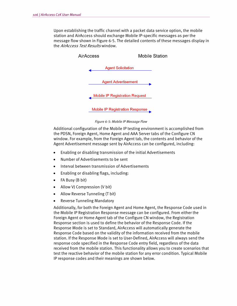
106 | AirAccess C2K User Manual
Upon establishing the traffic channel with a packet data service option, the mobile station and AirAccess should exchange Mobile IP-specific messages as per the message flow shown in Figure 6-5. The detailed contents of these messages display in the AirAccess Test Results window.
Figure 6-5: Mobile IP Message Flow
Additional configuration of the Mobile IP testing environment is accomplished from the PDSN, Foreign Agent, Home Agent and AAA Server tabs of the Configure CN window. For example, from the Foreign Agent tab, the contents and behavior of the Agent Advertisement message sent by AirAccess can be configured, including:
• Enabling or disabling transmission of the initial Advertisements
• Number of Advertisements to be sent
• Interval between transmission of Advertisements
• Enabling or disabling flags, including:
• FA Busy (B bit)
• Allow VJ Compression (V bit)
• Allow Reverse Tunneling (T bit)
• Reverse Tunneling Mandatory
Additionally, for both the Foreign Agent and Home Agent, the Response Code used in the Mobile IP Registration Response message can be configured. From either the Foreign Agent or Home Agent tab of the Configure CN window, the Registration Response section is used to define the behavior of the Response Code. If the Response Mode is set to Standard, AirAccess will automatically generate the Response Code based on the validity of the information received from the mobile station. If the Response Mode is set to User-Defined, AirAccess will always send the response code specified in the Response Code entry field, regardless of the data received from the mobile station. This functionality allows you to create scenarios that test the reactive behavior of the mobile station for any error condition. Typical Mobile IP response codes and their meanings are shown below.
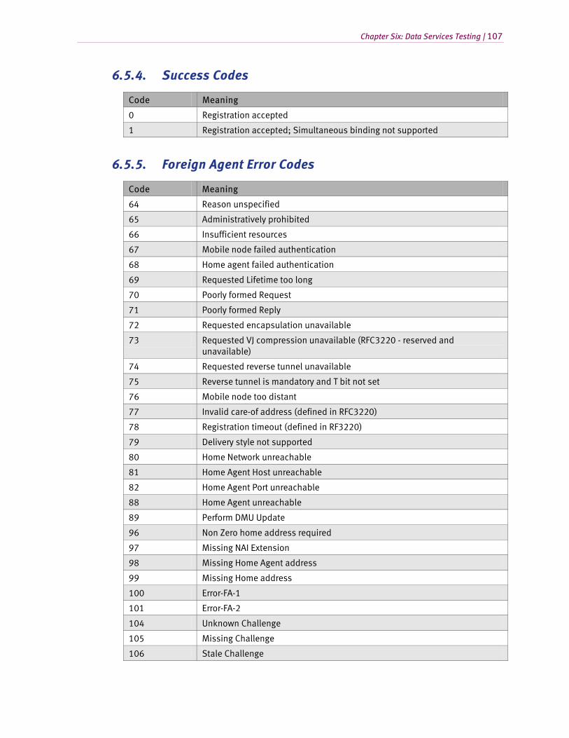
Chapter Six: Data Services Testing | 107
6.5.4. Success Codes
Code Meaning
0 Registration accepted
1 Registration accepted; Simultaneous binding not supported
6.5.5. Foreign Agent Error Codes
Code Meaning
64 Reason unspecified
65 Administratively prohibited
66 Insufficient resources
67 Mobile node failed authentication
68 Home agent failed authentication
69 Requested Lifetime too long
70 Poorly formed Request
71 Poorly formed Reply
72 Requested encapsulation unavailable
73 Requested VJ compression unavailable (RFC3220 - reserved and unavailable)
74 Requested reverse tunnel unavailable
75 Reverse tunnel is mandatory and T bit not set
76 Mobile node too distant
77 Invalid care-of address (defined in RFC3220)
78 Registration timeout (defined in RF3220)
79 Delivery style not supported
80 Home Network unreachable
81 Home Agent Host unreachable
82 Home Agent Port unreachable
88 Home Agent unreachable
89 Perform DMU Update
96 Non Zero home address required
97 Missing NAI Extension
98 Missing Home Agent address
99 Missing Home address
100 Error-FA-1
101 Error-FA-2
104 Unknown Challenge
105 Missing Challenge
106 Stale Challenge
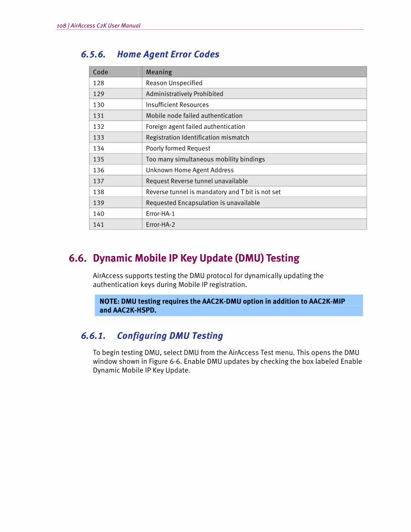
108 | AirAccess C2K User Manual
6.5.6. Home Agent Error Codes
Code Meaning
128 Reason Unspecified
129 Administratively Prohibited
130 Insufficient Resources
131 Mobile node failed authentication
132 Foreign agent failed authentication
133 Registration Identification mismatch
134 Poorly formed Request
135 Too many simultaneous mobility bindings
136 Unknown Home Agent Address
137 Request Reverse tunnel unavailable
138 Reverse tunnel is mandatory and T bit is not set
139 Requested Encapsulation is unavailable
140 Error-HA-1
141 Error-HA-2
6.6. Dynamic Mobile IP Key Update (DMU) Testing
AirAccess supports testing the DMU protocol for dynamically updating the authentication keys during Mobile IP registration.
NOTE: DMU testing requires the AAC2K-DMU option in addition to AAC2K-MIP and AAC2K-HSPD.
6.6.1. Configuring DMU Testing
To begin testing DMU, select DMU from the AirAccess Test menu. This opens the DMU window shown in Figure 6-6. Enable DMU updates by checking the box labeled Enable Dynamic Mobile IP Key Update.
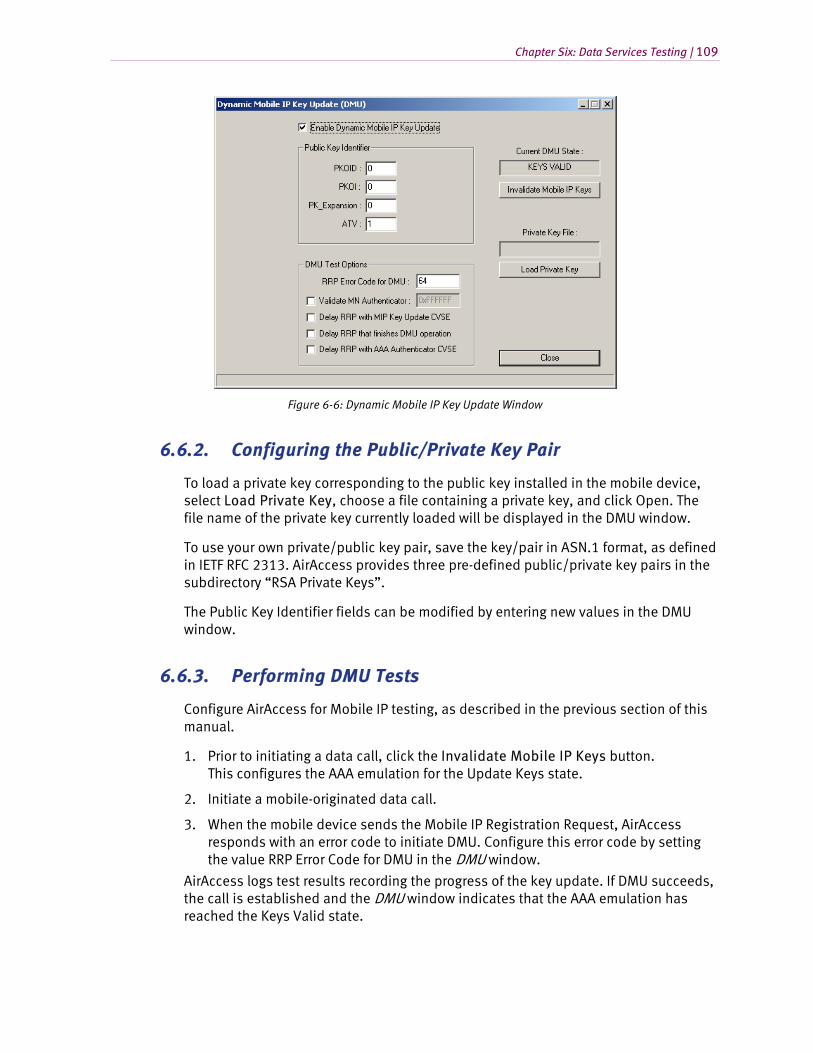
Chapter Six: Data Services Testing | 109
Figure 6-6: Dynamic Mobile IP Key Update Window
6.6.2. Configuring the Public/Private Key Pair
To load a private key corresponding to the public key installed in the mobile device, select Load Private Key, choose a file containing a private key, and click Open. The file name of the private key currently loaded will be displayed in the DMU window.
To use your own private/public key pair, save the key/pair in ASN.1 format, as defined in IETF RFC 2313. AirAccess provides three pre-defined public/private key pairs in the subdirectory “RSA Private Keys”.
The Public Key Identifier fields can be modified by entering new values in the DMU window.
6.6.3. Performing DMU Tests
Configure AirAccess for Mobile IP testing, as described in the previous section of this manual.
1. Prior to initiating a data call, click the Invalidate Mobile IP Keys button. This configures the AAA emulation for the Update Keys state.
2. Initiate a mobile-originated data call.
3. When the mobile device sends the Mobile IP Registration Request, AirAccess responds with an error code to initiate DMU. Configure this error code by setting the value RRP Error Code for DMU in the DMU window.
AirAccess logs test results recording the progress of the key update. If DMU succeeds, the call is established and the DMU window indicates that the AAA emulation has reached the Keys Valid state.
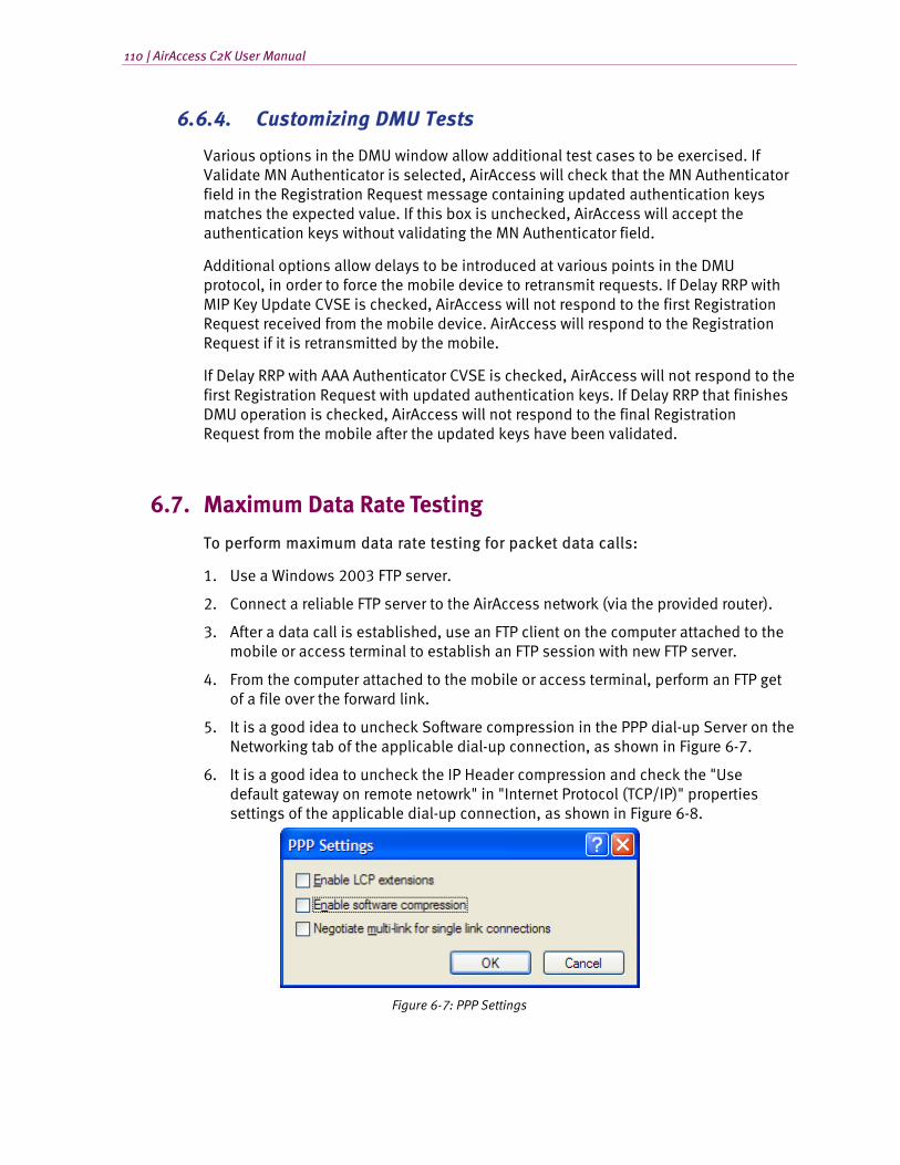
110 | AirAccess C2K User Manual
6.6.4. Customizing DMU Tests
Various options in the DMU window allow additional test cases to be exercised. If Validate MN Authenticator is selected, AirAccess will check that the MN Authenticator field in the Registration Request message containing updated authentication keys matches the expected value. If this box is unchecked, AirAccess will accept the authentication keys without validating the MN Authenticator field.
Additional options allow delays to be introduced at various points in the DMU protocol, in order to force the mobile device to retransmit requests. If Delay RRP with MIP Key Update CVSE is checked, AirAccess will not respond to the first Registration Request received from the mobile device. AirAccess will respond to the Registration Request if it is retransmitted by the mobile.
If Delay RRP with AAA Authenticator CVSE is checked, AirAccess will not respond to the first Registration Request with updated authentication keys. If Delay RRP that finishes DMU operation is checked, AirAccess will not respond to the final Registration Request from the mobile after the updated keys have been validated.
6.7. Maximum Data Rate Testing
To perform maximum data rate testing for packet data calls:
1. Use a Windows 2003 FTP server.
2. Connect a reliable FTP server to the AirAccess network (via the provided router).
3. After a data call is established, use an FTP client on the computer attached to the mobile or access terminal to establish an FTP session with new FTP server.
4. From the computer attached to the mobile or access terminal, perform an FTP get of a file over the forward link.
5. It is a good idea to uncheck Software compression in the PPP dial-up Server on the Networking tab of the applicable dial-up connection, as shown in Figure 6-7.
6. It is a good idea to uncheck the IP Header compression and check the "Use default gateway on remote netowrk" in "Internet Protocol (TCP/IP)" properties settings of the applicable dial-up connection, as shown in Figure 6-8.
Figure 6-7: PPP Settings
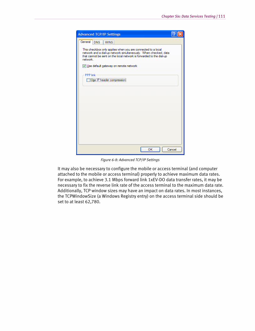
Chapter Six: Data Services Testing | 111
Figure 6-8: Advanced TCP/IP Settings
It may also be necessary to configure the mobile or access terminal (and computer attached to the mobile or access terminal) properly to achieve maximum data rates. For example, to achieve 3.1 Mbps forward link 1xEV-DO data transfer rates, it may be necessary to fix the reverse link rate of the access terminal to the maximum data rate. Additionally, TCP window sizes may have an impact on data rates. In most instances, the TCPWindowSize (a Windows Registry entry) on the access terminal side should be set to at least 62,780.
112 | AirAccess C2K User Manual
6.8. Troubleshooting Data Service Tests
This section describes several error messages that may be logged while running data service tests:
• MS-terminated data call failed
• Mobile is busy with another call
• Failed to create a network connection
• Failed to create a network connection in Mobile IP test scenario
6.8.1. MS-Terminated Data Call Failed
Possible causes:
• A MS-terminated data call was initiated from the land-side terminal application without first starting call processing and/or registering the mobile. Verify that AirAccess has connected to the SR3452 V2, call processing has been enabled (and the mobile sees service), and the mobile can be successfully registered before retrying the call.
• A configuration or protocol error prevented the call from going through.
• Examine the message log to determine the reason that the call could not be established.
6.8.2. Mobile is Busy with Another Call
Possible causes:
• A packet data call was in the dormant state when an MS-terminated async call was attempted. End the packet call before attempting to place an async data call.
• A voice call was established while a packet data call was in the dormant state. Later, a data application attempted to send more data over the dormant link, but the data call could not be reestablished because the voice call was active.
• The data that could not be sent will be discarded. The voice call will remain active.
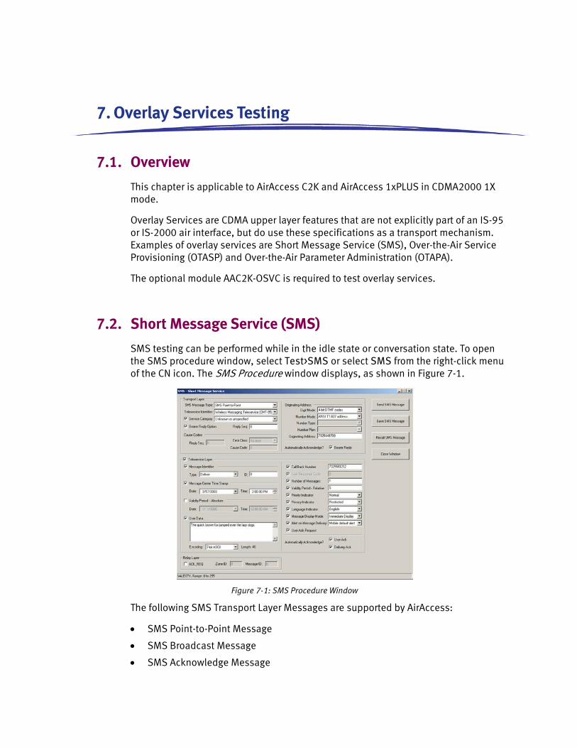
7. Overlay Services Testing
7.1. Overview
This chapter is applicable to AirAccess C2K and AirAccess 1xPLUS in CDMA2000 1X mode.
Overlay Services are CDMA upper layer features that are not explicitly part of an IS-95 or IS-2000 air interface, but do use these specifications as a transport mechanism. Examples of overlay services are Short Message Service (SMS), Over-the-Air Service Provisioning (OTASP) and Over-the-Air Parameter Administration (OTAPA).
The optional module AAC2K-OSVC is required to test overlay services.
7.2. Short Message Service (SMS)
SMS testing can be performed while in the idle state or conversation state. To open the SMS procedure window, select Test>SMS or select SMS from the right-click menu of the CN icon. The SMS Procedure window displays, as shown in Figure 7-1.
Figure 7-1: SMS Procedure Window
The following SMS Transport Layer Messages are supported by AirAccess:
• SMS Point-to-Point Message
• SMS Broadcast Message
• SMS Acknowledge Message
114 | AirAccess C2K User Manual
7.2.1. Mobile Terminated SMS
Mobile terminated SMS is performed by first selecting the SMS Point-to-Point Transport Layer Message. One of the following Teleservices is then selected:
• Wireless Paging Teleservice (CPT-95)
• Wireless Messaging Teleservice (CMT-95)
• Voice Mail Notification (VMN-95)
Reply and Bearer Data options can then be specified, including User Data text.
To send the SMS message on the Paging Channel, click Send SMS Message while in the Idle State to generate the message to the mobile station.
To send the SMS message on the Forward Traffic Channel, an SMS call must first be established. This can be accomplished by performing the following steps:
Ensure that an SMS service option (SO6 or SO14) is the primary service option configured in the Configure Service Negotiation window (see Section 4.8)
Verify the mobile station has registered (see Section 3.6)
Generate a mobile terminated call by selecting Call>Initiate MS-Terminated Call or selecting Initiate MS-Terminated Call from the right-click menu of a BSC icon
After the call completes, verify the selected SMS service option is active as indicated in the Test Results window
Click Send SMS Message to send the SMS message on the traffic channel
End the call by selecting Call>End Call or selecting End Call from the right-click menu of the BSC icon
Contents of the SMS message and the mobile station’s response are displayed in the Test Results window.
7.2.2. Mobile Originated SMS
NOTE: Prior to performing Mobile Originated SMS testing, it is important that the mobile station first identifies itself to AirAccess. This can be accomplished by forcing a mobile station registration (Call>Force MS Registration).
Mobile originated SMS can be performed at any time after the mobile station has identified itself to AirAccess. The contents of any SMS message received by AirAccess from the mobile station, as well as the acknowledgement message sent back to the mobile station, are displayed in the Test Results window.
The contents of the acknowledgement message can be customized by selecting the SMS Acknowledge Transport Layer Message. Once this message is selected, the Error Class and Cause Code parameters returned to the mobile station can be configured.
Chapter Seven: Overlay Services Testing | 115
7.2.3. Broadcast SMS
Broadcast SMS is performed by first selecting the SMS Broadcast Transport Layer Message. Bearer Data options can then be specified.
AirAccess implements Multi-Slot Broadcast Message Transmission or Periodic Broadcast Paging to deliver broadcast SMS messages.
To enable Periodic Broadcast Paging, the BCAST_INDEX parameter of the Extended System Parameters Message must be set to a non-zero value.
To set this parameter:
1. Open the Configure BTS window of the BTS that will be used for testing by double-clicking on its BTS icon
2. Select the Extended System Parameters Message from the Configure Overhead Messages list
3. Select the BCAST_INDEX message field and change the value to a non-zero entry corresponding to the desired broadcast slot cycle index
4. Click the OK button to exit the window
5. If the BCAST_INDEX parameter is set to zero on a given BTS, AirAccess will implement Multi-Slot Broadcasting on that BTS.
7.2.4. Saving and Recalling SMS Messages
To facilitate sending multiple SMS messages, AirAccess provides the ability to save and recall user-defined SMS messages.
Perform the following steps to save an SMS message:
1. Use the SMS Procedure Window (shown in Figure 7-1) to generate the contents of the desired SMS message.
2. After composing the message and configuring all desired flags, click the Save SMS Message button.
3. This will launch a Save As window. Enter a filename to save the SMS message. By default, saved SMS messages are stored in the SMS Message Definitions subdirectory.
Perform the following steps to recall a previously saved SMS message:
1. Open the SMS Procedure Window (shown in Figure 7-1).
2. From within this window, click the Recall SMS Message button.
3. This will launch an Open window. Browse to the desired SMS message file, highlight the file, and click the Open button.
4. The contents of the saved SMS message file will automatically be populated in the SMS Procedure Window.
116 | AirAccess C2K User Manual
5. Once the message is displayed, the Send SMS Message button can be clicked to send the recalled message to the mobile under test.
7.3. Multimedia Messaging Service (MMS)
AirAccess emulates a SMSC client and uses SMPP protocol to talk to a third party MMS server for MMS testing. AirAccess has been tested to interwork with NoWMMS server using specific SMPP defined PDUs. AirAccess supports both mobile originated and mobile terminated MMS capability. To be able to perform mobile originated MMS, Simple DNS is required to be installed on the AirAccess controller PC and provisioned so that the mobile can resolve the MMS/WAP server address.
AirAccess requires the following software option to be able to perform SMSC client function:
• AAC2K-SMSC-CLNT SMSC Client software option
The required provisioning documentation for AirAccess, Simple DNS, and NowMMS is provided when customer purchases the above option.
Note: Please note that it is the responsibility of the user to secure NowMMS license for MMS testing. AirAccess does not provide or ships with NoWMMS server.
7.4. OTA Service Provisioning and Parameter Administration
WARNING: Performing OTASP and/or OTAPA tests could result in permanent changes to the stored configuration of the Mobile Station under Test.
Over-the-Air Service Provisioning (OTASP) and Over-the-Air Parameter Administration (OTAPA) are features designed to allow remote activation and configuration of parameters within a mobile device. In general, OTASP is a procedure used to activate a new mobile device and the process is initiated at the mobile device. OTAPA is typically a network-initiated process used to update parameters in an already activated mobile device.
AirAccess provides support of both OTASP and OTAPA testing using the protocol defined in IS-683A, IS-683B, IS-683C, IS-683D, and IS-683E.
7.4.1. OTASP Testing
To initiate an OTASP testing session, it is first necessary to originate a call from the Mobile Station under Test. Typically a voice call is used for this testing.
NOTE: Many test plans will specify a specific activation code must be used to originate an OTASP call (for example, *22801). While these codes can be used to originate the call, AirAccess C2K does not require any specific digits be used to originate the call.
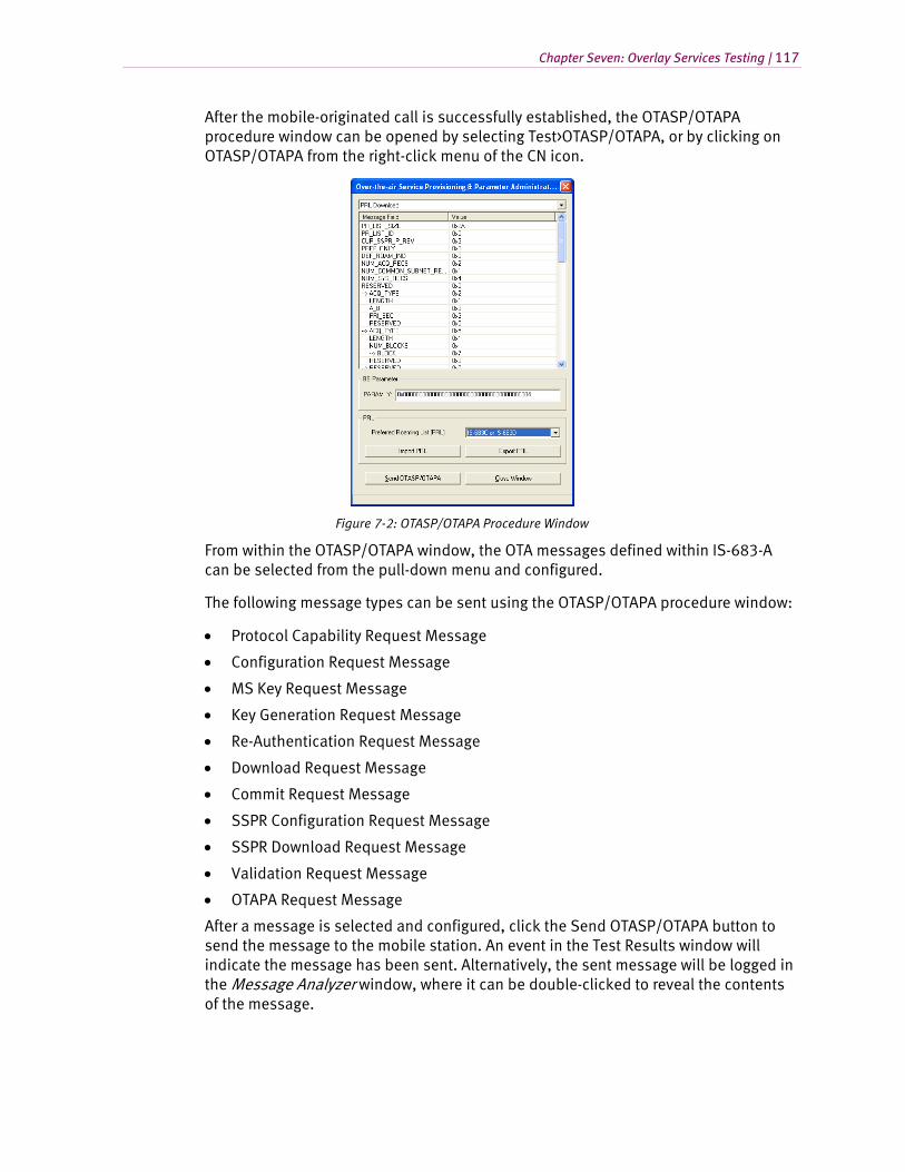
Chapter Seven: Overlay Services Testing | 117
After the mobile-originated call is successfully established, the OTASP/OTAPA procedure window can be opened by selecting Test>OTASP/OTAPA, or by clicking on OTASP/OTAPA from the right-click menu of the CN icon.
Figure 7-2: OTASP/OTAPA Procedure Window
From within the OTASP/OTAPA window, the OTA messages defined within IS-683-A can be selected from the pull-down menu and configured.
The following message types can be sent using the OTASP/OTAPA procedure window:
• Protocol Capability Request Message
• Configuration Request Message
• MS Key Request Message
• Key Generation Request Message
• Re-Authentication Request Message
• Download Request Message
• Commit Request Message
• SSPR Configuration Request Message
• SSPR Download Request Message
• Validation Request Message
• OTAPA Request Message
After a message is selected and configured, click the Send OTASP/OTAPA button to send the message to the mobile station. An event in the Test Results window will indicate the message has been sent. Alternatively, the sent message will be logged in the Message Analyzer window, where it can be double-clicked to reveal the contents of the message.
118 | AirAccess C2K User Manual
Typically, the first message that is sent at the start of an OTASP session is the Protocol Capability Request Message. This request will ask the mobile station to respond with which OTASP features it supports. Results of all OTASP message exchanges can be viewed in the Test Results window. If changes are made to the NAM parameters of the mobile station during the OTASP session, a Commit Request Message must be sent to the mobile station. This will instruct the mobile station to move the changes from temporary memory to permanent memory.
7.4.2. OTAPA Testing
To initiate an OTAPA testing session, it is first necessary to have a call established between AirAccess and the Mobile Station under Test. OTAPA testing sessions can be done either on voice calls (where OTAPA messages are exchanged in the background while a voice call is active) or on OTAPA-specific service option calls.
7.4.2.1 OTAPA Testing on Voice Calls
Since OTAPA is designed to update parameters within a mobile station that is already active on a network, one strategy that can be used by a network operator is to wait until the next time the mobile station is on a call, and then update parameters in the background.
To perform this type of OTAPA testing, it is first necessary to establish either a mobile-originated or mobile-terminated voice call. Ensure that the primary service configuration within AirAccess’ Service Negotiation window is set for a voice service option (Service Options 1, 3, 17 or 32768). Refer to Section 4.8.
Originate a call from the mobile station, or command AirAccess to perform a mobile-terminated call. After the voice call is successfully established, the OTASP/OTAPA procedure window can be opened by selecting Test>OTASP/OTAPA, or by clicking on OTASP/OTAPA from the right-click menu of the CN icon. The window shown in Figure 7-2 displays. All of the IS-683-A messages available for OTASP testing (see Section 7.3.1) are also available for OTAPA testing.
Typically, the first message that is sent at the start of an OTAPA session is the OTAPA Request Message with the START_STOP field set to ‘1’. This indicates to the mobile station that an OTAPA session is being started. Results of all OTAPA message exchanges can be viewed in the Test Results window. If changes are made to the NAM parameters of the mobile station during the OTASP session, a Commit Request Message must be sent to the mobile station. This will instruct the mobile station to move the changes from temporary memory to permanent memory. The final message typically sent at the end of an OTAPA session is the OTAPA Request Message with the START_STOP field set to ‘0’. This indicates to the mobile station that an OTAPA session is being ended.
Chapter Seven: Overlay Services Testing | 119
7.4.2.2 OTAPA Testing on an OTAPA-specific Service Option Call
Another strategy used by service provides for OTAPA updating of mobile stations is to establish a dedicated call for the OTAPA session. This option always uses a mobile-terminated call. The mobile station should make no indication that an OTAPA call is underway (i.e. the mobile should not ring and the mobile’s user interface should not indicate a call is active).
To perform this type of OTAPA testing, it is first necessary to establish a mobile-terminated call using an OTAPA-specific service option. Ensure that the primary service configuration within AirAccess’ Service Negotiation window is set for an OTAPA-specific service option as follows:
• For a 9.6 kbps (Rate Set 1) OTAPA call, use Service Option 18
• For a 14.4 kbps (Rate Set 2) OTAPA call, use Service Option 19
Command AirAccess to perform a mobile-terminated call. After the OTAPA call is successfully established, the OTASP/OTAPA procedure window can be opened by selecting Test>OTASP/OTAPA, or by clicking on OTASP/OTAPA from the right-click menu of the CN icon. The window shown in Figure 7-2 will appear. All of the IS-683-A messages available for OTASP testing (see Section 7.3.1) are also available for OTAPA testing.
Typically, the first message that is sent at the start of an OTAPA session is the OTAPA Request Message with the START_STOP field set to ‘1’. This indicates to the mobile station that an OTAPA session is being started. Results of all OTAPA message exchanges can be viewed in the Test Results window. If changes are made to the NAM parameters of the mobile station during the OTASP session, a Commit Request Message must be sent to the mobile station. This will instruct the mobile station to move the changes from temporary memory to permanent memory. The final message typically sent at the end of an OTAPA session is the OTAPA Request Message with the START_STOP field set to ‘0’. This indicates to the mobile station that an OTAPA session is being ended.
7.4.3. PRL Operations with OTASP/OTAPA
WARNING: Performing PRL operation tests could result in permanent changes to the stored PRL of the Mobile Station under Test. This could prevent the mobile station from acquiring service after testing completes. Verify the selected PRL is valid for the mobile station.
AirAccess implements macro functions to facilitate uploading and downloading Preferred Roaming Lists (PRLs) to and from a mobile station via OTASP and OTAPA. These macros automatically generate a series of IS-683 messages necessary to transfer a PRL. The following macro functions are available:
• PRL Download
• PRL Upload
120 | AirAccess C2K User Manual
Once an OTASP or OTAPA session has been established, a macro can be selected from the pull-down list in the OTASP/OTAPA procedure window.
When the PRL Download macro is selected from the pull-down list, an Open PRL button becomes active in the OTASP/OTAPA procedure window. If selected, this button will open a dialog window where the operator can browse and select a formatted PRL file. The contents of the selected PRL file will automatically populate the OTASP/OTAPA procedure window. A pull-down list is used to select between the IS-683-A, -B, or -C/D/E PRL formats.
Alternatively, the operator can manually enter or modify a PRL via the field displayed in the OTASP/OTAPA procedure window. Clicking the Send OTASP/OTAPA button will cause the PRL contents displayed in the OTASP/OTAPA procedure window to be sent to the mobile station.
When the PRL Upload macro is selected from the pull-down list, clicking the Send OTASP/OTAPA button will cause AirAccess to generate the series of commands necessary to query the current PRL stored in the mobile station. After the query is complete, the PRL retrieved from the mobile station will be displayed in the OTASP/OTAPA procedure window. Clicking the Export PRL button will then give the operator the ability to specify a filename and save the PRL contents to an file.
8. Using TAP Protocols
8.1. Overview
The Test Application Specification (TAS) for High Rate Packet Data Air Interface specifies four independent protocols to conduct access terminal minimum performance tests in laboratory environment. This specification also allows you to conduct measurements of certain forward link and reverse link performance in a field environment.
The six protocols are:
1. Forward Test Application Protocol (FTAP).
2. Reverse Test Application Protocol (RTAP).
3. Forward Enhanced Test Application Protocol (FETAP).
4. Reverse Enhanced Test Application Protocol (RETAP).
5. Forward Multicarrier Test Application Protocol (FMCTAP)
6. Reverse Multicarrier Test Application Protocol (RMCTAP)
AirAccess provides the ability to perform testing using all of the above six protocols.
To use these protocols, bind them to the stream you want to use, and initiate the TAP calls. You can perform these operations using the I-APIs provided by AirAccess. For further information about the I-APIs required for TAP testing, refer to the AirAccess I-API Command Reference Manual delivered as part of the I-API SDK (Software Development Kit) option.
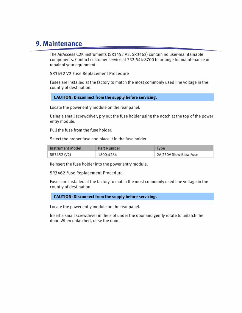
9. Maintenance The AirAccess C2K instruments (SR3452 V2, SR3462) contain no user-maintainable components. Contact customer service at 732-544-8700 to arrange for maintenance or repair of your equipment.
SR3452 V2 Fuse Replacement Procedure
Fuses are installed at the factory to match the most commonly used line voltage in the country of destination.
CAUTION: Disconnect from the supply before servicing.
Locate the power entry module on the rear panel.
Using a small screwdriver, pry out the fuse holder using the notch at the top of the power entry module.
Pull the fuse from the fuse holder.
Select the proper fuse and place it in the fuse holder.
Instrument Model Part Number Type
SR3452 (V2) 1800-4284 2A 250V Slow-Blow Fuse
Reinsert the fuse holder into the power entry module.
SR3462 Fuse Replacement Procedure
Fuses are installed at the factory to match the most commonly used line voltage in the country of destination.
CAUTION: Disconnect from the supply before servicing.
Locate the power entry module on the rear panel.
Insert a small screwdriver in the slot under the door and gently rotate to unlatch the door. When unlatched, raise the door.
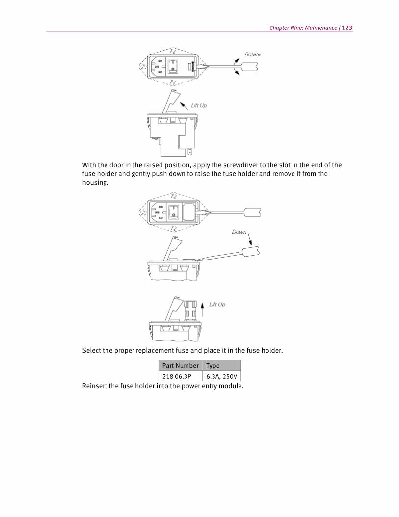
Chapter Nine: Maintenance | 123
With the door in the raised position, apply the screwdriver to the slot in the end of the fuse holder and gently push down to raise the fuse holder and remove it from the housing.
Select the proper replacement fuse and place it in the fuse holder.
Part Number Type
218 06.3P 6.3A, 250V
Reinsert the fuse holder into the power entry module.
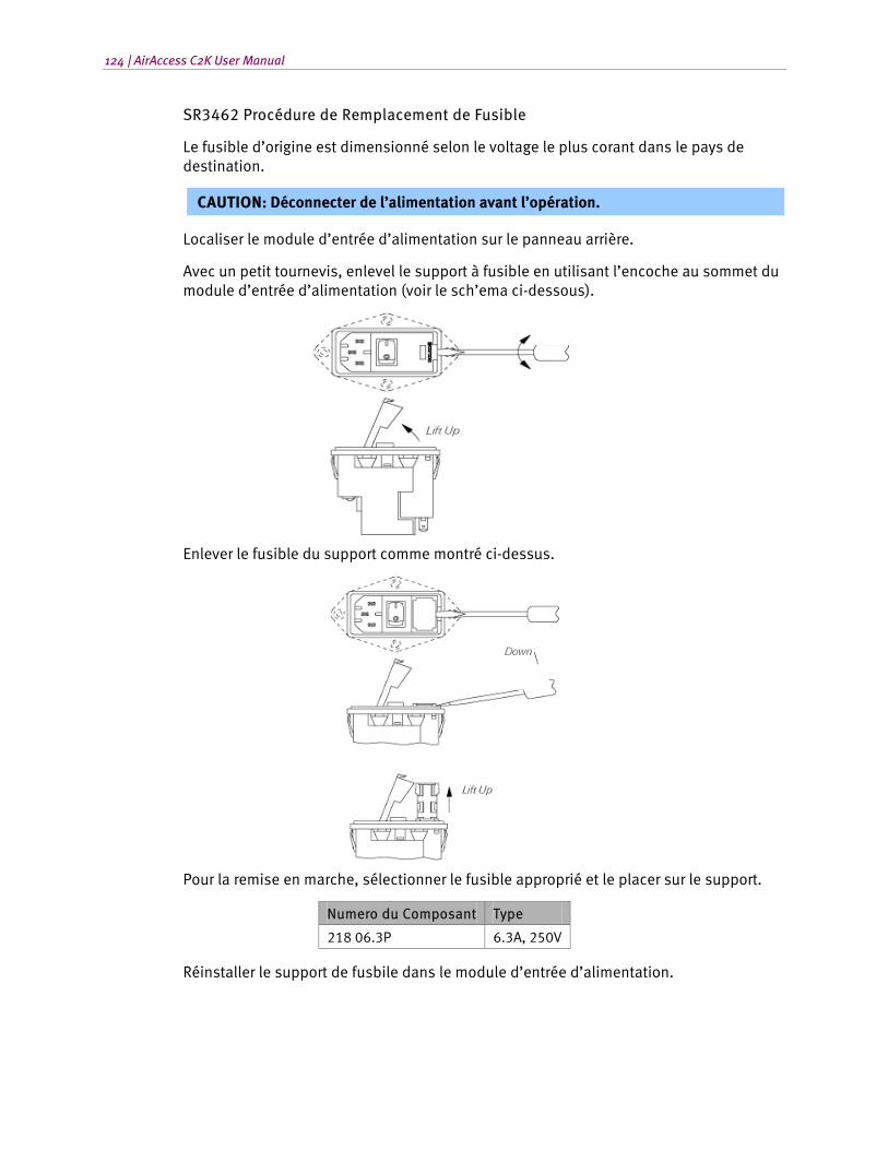
124 | AirAccess C2K User Manual
SR3462 Procédure de Remplacement de Fusible
Le fusible d’origine est dimensionné selon le voltage le plus corant dans le pays de destination.
CAUTION: Déconnecter de l’alimentation avant l’opération.
Localiser le module d’entrée d’alimentation sur le panneau arrière.
Avec un petit tournevis, enlevel le support à fusible en utilisant l’encoche au sommet du module d’entrée d’alimentation (voir le sch’ema ci-dessous).
Enlever le fusible du support comme montré ci-dessus.
Pour la remise en marche, sélectionner le fusible approprié et le placer sur le support.
Numero du Composant Type
218 06.3P 6.3A, 250V
Réinstaller le support de fusbile dans le module d’entrée d’alimentation.
10. Technical Specifications
10.1. Overview
The following specifications describe performance over the temperature range 0-40 degrees C, and include a 30 minute warm-up time from ambient conditions. All specifications are measured at 892.7 MHz and 1962.5 MHz unless stated otherwise. Supplemental characteristics provide useful information by giving performance parameters not under warranty.
10.2. RF Generator
Pilot Relative Level: -63.0 to -0.1 dB (0.1 dB res)
Sync Relative Level: -63.0 to -0.1 dB (0.1 dB res)
Paging Relative Level: -63.0 to -0.1 dB (0.1 dB res)
QPCH Relative Level: -63.0 to -0.1 dB (0.1 dB res)
FCH Relative Level: -63.0 to -0.1 dB (0.1 dB res)
SCH Relative Level: -63.0 to -0.1 dB (0.1 dB res)
OCNS Walsh Code Length: Fixed to 64
OCNS Relative Level Range: Calculated automatically from the relative levels of the other code channels to provide a composite power level that is equal to the programmed sector power
CDMA Modulation
Modulation Type
1X: Parallel BPSK for Pilot, Sync and Paging channels; Complex QPSK for FHS and SCH channels
1xEV-DO: QPSK, 8-PSK, 16-QAM
126 | AirAccess C2K User Manual
The following additional RF Generator specifications are applicable when the SR3452 V2 is used for RF conversion:
Independent RF Carriers: 1 RF output per SR3452 V2
Frequency
Frequency Range: Band Class 0 (866 MHz to 894 MHz)
Band Class 1 (1930 MHz to 1990 MHz)
Band Class 3 (832 MHz to 869 MHz)
Band Class 4 (1840 MHz to 1870 MHz)
Band Class 5 (421 MHz to 494 MHz)
Band Class 6 (2110 MHz to 2170 MHz)
Band Class 10 (851 MHz to 940 MHz)
Band Class 14 (1930 MHz to 1995 MHz)
Band Class 15 (2110 MHz to 2155 MHz)
Frequency Resolution: 500 Hz
Frequency Setting: By channel number
Amplitude
RF Output Level Range: -100 dBm/1.23 MHz to -38 dBm/1.23 MHz
RF Output Level Resolution: 0.1 dB
Absolute Output Level Accuracy: ±1 dB
CDMA Modulation Quality: Residual Rho > 0.99
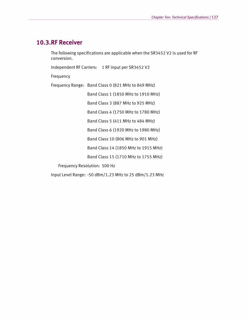
Chapter Ten: Technical Specifications | 127
10.3. RF Receiver
The following specifications are applicable when the SR3452 V2 is used for RF conversion.
Independent RF Carriers: 1 RF input per SR3452 V2
Frequency
Frequency Range: Band Class 0 (821 MHz to 849 MHz)
Band Class 1 (1850 MHz to 1910 MHz)
Band Class 3 (887 MHz to 925 MHz)
Band Class 4 (1750 MHz to 1780 MHz)
Band Class 5 (411 MHz to 484 MHz)
Band Class 6 (1920 MHz to 1980 MHz)
Band Class 10 (806 MHz to 901 MHz)
Band Class 14 (1850 MHz to 1915 MHz)
Band Class 15 (1710 MHz to 1755 MHz)
Frequency Resolution: 500 Hz
Input Level Range: -50 dBm/1.23 MHz to 25 dBm/1.23 MHz
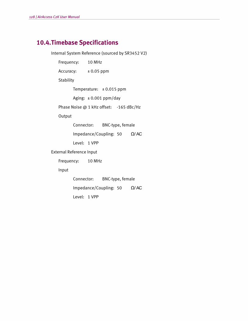
128 | AirAccess C2K User Manual
10.4. Timebase Specifications
Internal System Reference (sourced by SR3452 V2)
Frequency: 10 MHz
Accuracy: ± 0.05 ppm
Stability
Temperature: ± 0.015 ppm
Aging: ± 0.001 ppm/day
Phase Noise @ 1 kHz offset: -165 dBc/Hz
Output
Connector: BNC-type, female
Impedance/Coupling: 50 Ω/ AC
Level: 1 VPP
External Reference Input
Frequency: 10 MHz
Input
Connector: BNC-type, female
Impedance/Coupling: 50 Ω/ AC
Level: 1 VPP
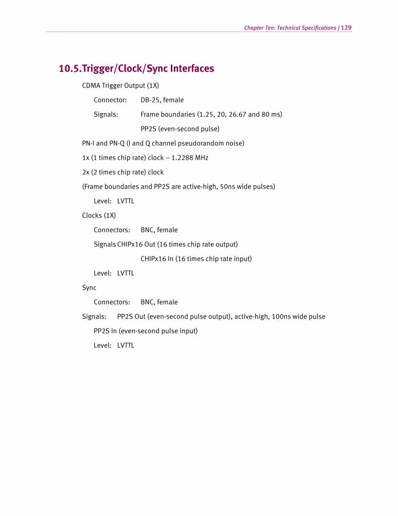
Chapter Ten: Technical Specifications | 129
10.5. Trigger/Clock/Sync Interfaces
CDMA Trigger Output (1X)
Connector: DB-25, female
Signals: Frame boundaries (1.25, 20, 26.67 and 80 ms)
PP2S (even-second pulse)
PN-I and PN-Q (I and Q channel pseudorandom noise)
1x (1 times chip rate) clock – 1.2288 MHz
2x (2 times chip rate) clock
(Frame boundaries and PP2S are active-high, 50ns wide pulses)
Level: LVTTL
Clocks (1X)
Connectors: BNC, female
Signals CHIPx16 Out (16 times chip rate output)
CHIPx16 In (16 times chip rate input)
Level: LVTTL
Sync
Connectors: BNC, female
Signals: PP2S Out (even-second pulse output), active-high, 100ns wide pulse
PP2S In (even-second pulse input)
Level: LVTTL
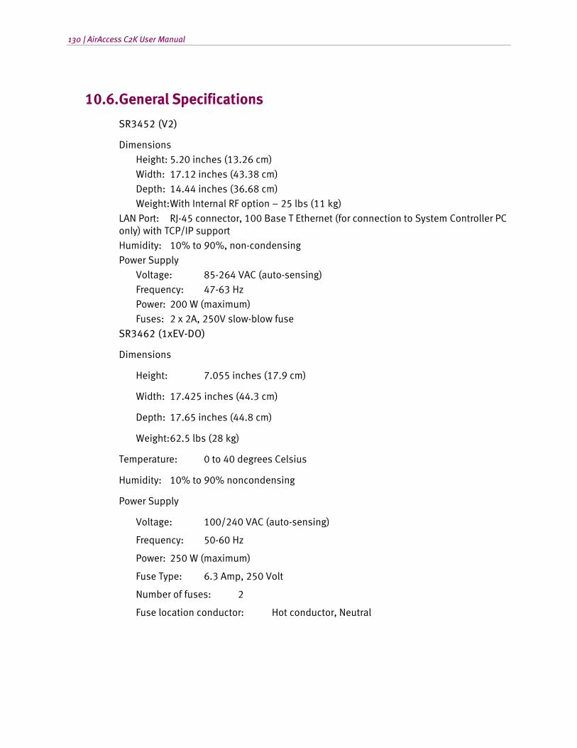
130 | AirAccess C2K User Manual
10.6. General Specifications
SR3452 (V2)
Dimensions Height: 5.20 inches (13.26 cm)
Width: 17.12 inches (43.38 cm) Depth: 14.44 inches (36.68 cm) Weight: With Internal RF option – 25 lbs (11 kg)
LAN Port: RJ-45 connector, 100 Base T Ethernet (for connection to System Controller PC only) with TCP/IP support Humidity: 10% to 90%, non-condensing Power Supply
Voltage: 85-264 VAC (auto-sensing) Frequency: 47-63 Hz Power: 200 W (maximum) Fuses: 2 x 2A, 250V slow-blow fuse
SR3462 (1xEV-DO)
Dimensions
Height: 7.055 inches (17.9 cm)
Width: 17.425 inches (44.3 cm)
Depth: 17.65 inches (44.8 cm)
Weight: 62.5 lbs (28 kg)
Temperature: 0 to 40 degrees Celsius
Humidity: 10% to 90% noncondensing
Power Supply
Voltage: 100/240 VAC (auto-sensing)
Frequency: 50-60 Hz
Power: 250 W (maximum)
Fuse Type: 6.3 Amp, 250 Volt
Number of fuses: 2
Fuse location conductor: Hot conductor, Neutral
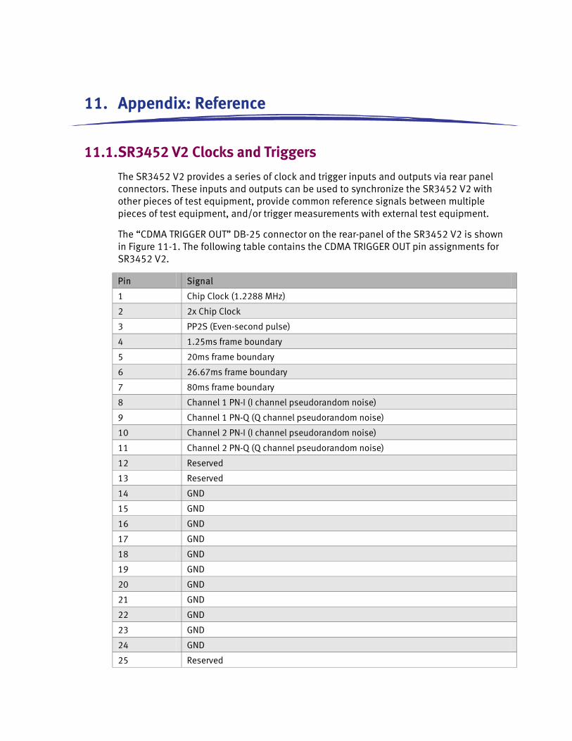
11. Appendix: Reference
11.1. SR3452 V2 Clocks and Triggers
The SR3452 V2 provides a series of clock and trigger inputs and outputs via rear panel connectors. These inputs and outputs can be used to synchronize the SR3452 V2 with other pieces of test equipment, provide common reference signals between multiple pieces of test equipment, and/or trigger measurements with external test equipment.
The “CDMA TRIGGER OUT” DB-25 connector on the rear-panel of the SR3452 V2 is shown in Figure 11-1. The following table contains the CDMA TRIGGER OUT pin assignments for SR3452 V2.
Pin Signal
1 Chip Clock (1.2288 MHz)
2 2x Chip Clock
3 PP2S (Even-second pulse)
4 1.25ms frame boundary
5 20ms frame boundary
6 26.67ms frame boundary
7 80ms frame boundary
8 Channel 1 PN-I (I channel pseudorandom noise)
9 Channel 1 PN-Q (Q channel pseudorandom noise)
10 Channel 2 PN-I (I channel pseudorandom noise)
11 Channel 2 PN-Q (Q channel pseudorandom noise)
12 Reserved
13 Reserved
14 GND
15 GND
16 GND
17 GND
18 GND
19 GND
20 GND
21 GND
22 GND
23 GND
24 GND
25 Reserved
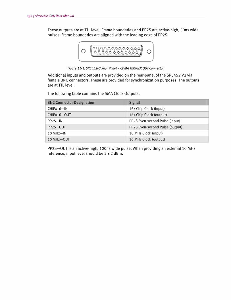
132 | AirAccess C2K User Manual
These outputs are at TTL level. Frame boundaries and PP2S are active-high, 50ns wide pulses. Frame boundaries are aligned with the leading edge of PP2S.
Figure 11-1: SR3452v2 Rear Panel – CDMA TRIGGER OUT Connector
Additional inputs and outputs are provided on the rear-panel of the SR3452 V2 via female BNC connectors. These are provided for synchronization purposes. The outputs are at TTL level.
The following table contains the SMA Clock Outputs.
BNC Connector Designation Signal
CHIPx16—IN 16x Chip Clock (input)
CHIPx16—OUT 16x Chip Clock (output)
PP2S—IN PP2S Even-second Pulse (input)
PP2S—OUT PP2S Even-second Pulse (output)
10 MHz—IN 10 MHz Clock (input)
10 MHz—OUT 10 MHz Clock (output)
PP2S—OUT is an active-high, 100ns wide pulse. When providing an external 10 MHz reference, input level should be 2 ± 2 dBm.