agilent fieldfox handheld analyzers€¦ · · 2013-06-06step 2. select optional measurement...
TRANSCRIPT
This configuration guide describes configurations, options, and accessories for the FieldFox family
of portable analyzers. This guide should be used in conjunction with the technical overviews and
data sheets for a complete description of the analyzers.
Agilent FieldFox Handheld Analyzers
4/6.5/9/14/18/26.5 GHz
Configuration Guide
Carry precision with you.
N9913A
NN99991144AA
N9915A
N9916A
NN99991177AA
N9918A
N9925A
N99992266A
N9927A
N9928A
N9935A
NN99993366AA
N9937A
N9938A

2
1 Return loss and VSWR measurements available.
The FieldFox analyzer familyThe table below shows a comparison of the functions available in the FieldFox family of analyzers.
Functionality
FieldFox RF and microwave analyzers
(Combination or combo analyzers)
N9913A, N9914AN9915A, N9916A N9917A, N9918A
FieldFox microwave vector network analyzers
N9925A, N9926A N9927A, N9928A
FieldFox microwave spectrum analyzers
N9935A, N9936A N9937A, N9938A
Cable and antenna analyzer (CAT) Yes Yes No1
Vector network analyzer (VNA) Yes Yes No
Spectrum analyzer (SA) Yes No Yes
Built-in power meter Yes Yes Yes
Vector voltmeter (VVM) Yes Yes No
The table below shows a comparison of the functions available in the FieldFox family of analyzers.
Option Description N991x Combo N992x VNA N993x SA
233 Spectrum analyzer √ - Base model
235 Preamplifier √ - √
220 Tracking generator Note 1 - √
236 Interference analyzer and spectrogram √ - √
305 Cable and antenna analyzer Base model √ Note 2
320 Reflection measurements (RL, VSWR) Note 3 Note 4 √
210 VNA transmission/reflection √ Base model -
211 VNA full 2-port S-parameters √ √ -
010 VNA time domain √ √ -
112 QuickCal √ √ -
308 Vector voltmeter √ √ -
307 Built-in GPS receiver √ √ √
302 USB power sensor support √ √ √
309 DC bias variable-voltage source √ √ √
310 Built-in power meter √ √ √
Base model means that the functionality listed is the primary function of that instrument. For example, on the N991xA combo analyzers, cable and antenna analysis is the standard function included with every N991xA. Notes:1. On the N991xA combination analyzers, order options 233 and 210 to obtain a tracking generator with the spectrum analyzer. Option 220 is
not applicable to the combination analyzers. Option 233 provides the spectrum analyzer capability and Option 210 the "tracking" capability.
2. Option 305 cable and antenna analyzer, is not available on the N993xA. However, a subset of cable and antenna analyzer
measurements return loss and VSWR, is available as Option 320.
3. Option 320 is not applicable to N991xA. The reflection measurements of return loss and VSWR are included with every N991xA. So
there is no need for an Option 320 on the combo analyzers.
4. Option 320 is not applicable to N992xA. The reflection measurements of return loss and VSWR are included with every N992xA. So
there is no need for an Option 320 on the N992xA.
3
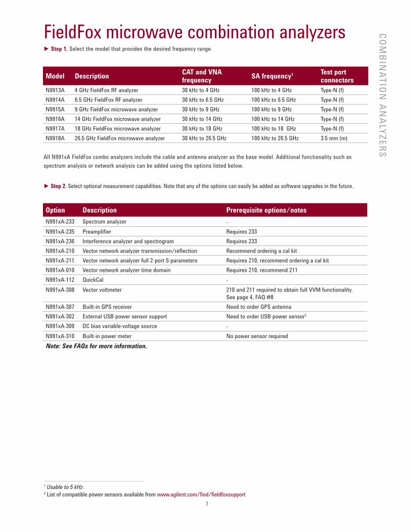
Model DescriptionCAT and VNA frequency
SA frequency1 Test port connectors
N9913A 4 GHz FieldFox RF analyzer 30 kHz to 4 GHz 100 kHz to 4 GHz Type-N (f)
N9914A 6.5 GHz FieldFox RF analyzer 30 kHz to 6.5 GHz 100 kHz to 6.5 GHz Type-N (f)
N9915A 9 GHz FieldFox microwave analyzer 30 kHz to 9 GHz 100 kHz to 9 GHz Type-N (f)
N9916A 14 GHz FieldFox microwave analyzer 30 kHz to 14 GHz 100 kHz to 14 GHz Type-N (f)
N9917A 18 GHz FieldFox microwave analyzer 30 kHz to 18 GHz 100 kHz to 18 GHz Type-N (f)
N9918A 26.5 GHz FieldFox microwave analyzer 30 kHz to 26.5 GHz 100 kHz to 26.5 GHz 3.5 mm (m)
All N991xA FieldFox combo analyzers include the cable and antenna analyzer as the base model. Additional functionality such as
spectrum analysis or network analysis can be added using the options listed below.
► Step 2. Select optional measurement capabilities. Note that any of the options can easily be added as software upgrades in the future.
Option Description Prerequisite options/notes
N991xA-233 Spectrum analyzer -
N991xA-235 Preamplifier Requires 233
N991xA-236 Interference analyzer and spectrogram Requires 233
N991xA-210 Vector network analyzer transmission/reflection Recommend ordering a cal kit
N991xA-211 Vector network analyzer full 2-port S-parameters Requires 210, recommend ordering a cal kit
N991xA-010 Vector network analyzer time domain Requires 210, recommend 211
N991xA-112 QuickCal -
N991xA-308 Vector voltmeter 210 and 211 required to obtain full VVM functionality.
See page 4, FAQ #8
N991xA-307 Built-in GPS receiver Need to order GPS antenna
N991xA-302 External USB power sensor support Need to order USB power sensor2
N991xA-309 DC bias variable-voltage source -
N991xA-310 Built-in power meter No power sensor required
Note: See FAQs for more information.
1 Usable to 5 kHz.2 List of compatible power sensors available from www.agilent.com/find/fieldfoxsupport
FieldFox microwave combination analyzers► Step 1. Select the model that provides the desired frequency range.
CO
MB
INA
TIO
N A
NA
LYZ
ER
S
4
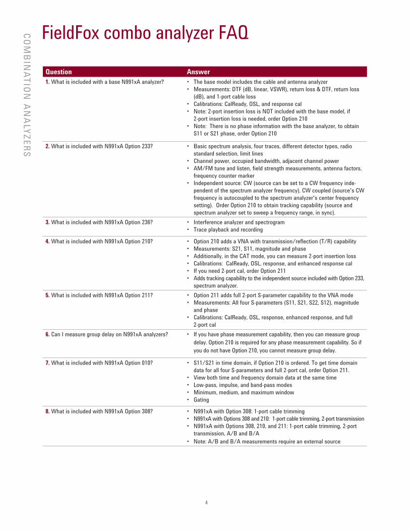
FieldFox combo analyzer FAQ
Question Answer
1. What is included with a base N991xA analyzer? • The base model includes the cable and antenna analyzer
• Measurements: DTF (dB, linear, VSWR), return loss & DTF, return loss
(dB), and 1-port cable loss
• Calibrations: CalReady, OSL, and response cal
• Note: 2-port insertion loss is NOT included with the base model, if
2-port insertion loss is needed, order Option 210
• Note: There is no phase information with the base analyzer, to obtain
S11 or S21 phase, order Option 210
2. What is included with N991xA Option 233? • Basic spectrum analysis, four traces, different detector types, radio
standard selection, limit lines
• Channel power, occupied bandwidth, adjacent channel power
• AM/FM tune and listen, field strength measurements, antenna factors,
frequency counter marker
• Independent source: CW (source can be set to a CW frequency inde-
pendent of the spectrum analyzer frequency), CW coupled (source's CW
frequency is autocoupled to the spectrum analyzer's center frequency
setting). Order Option 210 to obtain tracking capability (source and
spectrum analyzer set to sweep a frequency range, in sync).
3. What is included with N991xA Option 236? • Interference analyzer and spectrogram
• Trace playback and recording
4. What is included with N991xA Option 210? • Option 210 adds a VNA with transmission/reflection (T/R) capability
• Measurements: S21, S11, magnitude and phase
• Additionally, in the CAT mode, you can measure 2-port insertion loss
• Calibrations: CalReady, OSL, response, and enhanced response cal
• If you need 2-port cal, order Option 211
• Adds tracking capability to the independent source included with Option 233,
spectrum analyzer.
5. What is included with N991xA Option 211? • Option 211 adds full 2-port S-parameter capability to the VNA mode
• Measurements: All four S-parameters (S11, S21, S22, S12), magnitude
and phase
• Calibrations: CalReady, OSL, response, enhanced response, and full
2-port cal
6. Can I measure group delay on N991xA analyzers? • If you have phase measurement capability, then you can measure group
delay. Option 210 is required for any phase measurement capability. So if
you do not have Option 210, you cannot measure group delay.
7. What is included with N991xA Option 010? • S11/S21 in time domain, if Option 210 is ordered. To get time domain
data for all four S-parameters and full 2-port cal, order Option 211.
• View both time and frequency domain data at the same time
• Low-pass, impulse, and band-pass modes
• Minimum, medium, and maximum window
• Gating
8. What is included with N991xA Option 308? • N991xA with Option 308: 1-port cable trimming
• N991xA with Options 308 and 210: 1-port cable trimming, 2-port transmission
• N991xA with Options 308, 210, and 211: 1-port cable trimming, 2-port
transmission, A/B and B/A
• Note: A/B and B/A measurements require an external source
CO
MB
INA
TIO
N A
NA
LYZ
ER
S
5
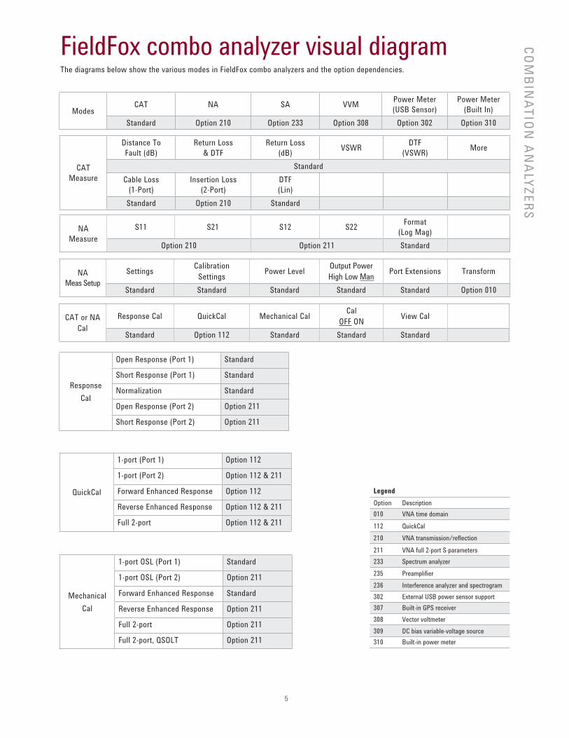
FieldFox combo analyzer visual diagramThe diagrams below show the various modes in FieldFox combo analyzers and the option dependencies.
CO
MB
INA
TIO
N A
NA
LYZ
ER
S
ModesCAT NA SA VVM
Power Meter
(USB Sensor)
Power Meter
(Built In)
Standard Option 210 Option 233 Option 308 Option 302 Option 310
CAT
Measure
Distance To
Fault (dB)
Return Loss
& DTF
Return Loss
(dB)VSWR
DTF
(VSWR)More
Standard
Cable Loss
(1-Port)
Insertion Loss
(2-Port)
DTF
(Lin)
Standard Option 210 Standard
NA
Measure
S11 S21 S12 S22Format
(Log Mag)
Option 210 Option 211 Standard
Response
Cal
Open Response (Port 1) Standard
Short Response (Port 1) Standard
Normalization Standard
Open Response (Port 2) Option 211
Short Response (Port 2) Option 211
QuickCal
1-port (Port 1) Option 112
1-port (Port 2) Option 112 & 211
Forward Enhanced Response Option 112
Reverse Enhanced Response Option 112 & 211
Full 2-port Option 112 & 211
Mechanical
Cal
1-port OSL (Port 1) Standard
1-port OSL (Port 2) Option 211
Forward Enhanced Response Standard
Reverse Enhanced Response Option 211
Full 2-port Option 211
Full 2-port, QSOLT Option 211
Legend
Option Description
010 VNA time domain
112 QuickCal
210 VNA transmission/reflection
211 VNA full 2-port S-parameters
233 Spectrum analyzer
235 Preamplifier
236 Interference analyzer and spectrogram
302 External USB power sensor support
307 Built-in GPS receiver
308 Vector voltmeter
309 DC bias variable-voltage source
310 Built-in power meter
NA
Meas Setup
SettingsCalibration
SettingsPower Level
Output Power
High Low ManPort Extensions Transform
Standard Standard Standard Standard Standard Option 010
CAT or NA
Cal
Response Cal QuickCal Mechanical CalCal
OFF ONView Cal
Standard Option 112 Standard Standard Standard
6
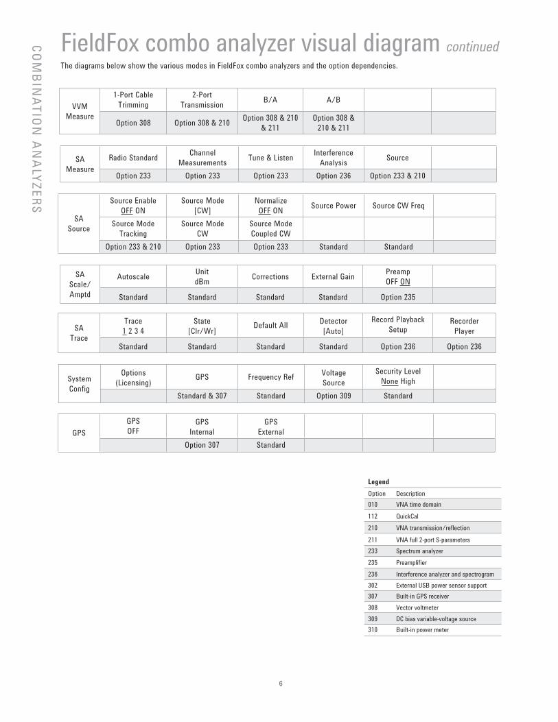
FieldFox combo analyzer visual diagram continuedThe diagrams below show the various modes in FieldFox combo analyzers and the option dependencies.
VVM
Measure
1-Port Cable
Trimming
2-Port
TransmissionB/A A/B
Option 308 Option 308 & 210Option 308 & 210
& 211
Option 308 &
210 & 211
SA
Measure
Radio StandardChannel
MeasurementsTune & Listen
Interference
AnalysisSource
Option 233 Option 233 Option 233 Option 236 Option 233 & 210
SA
Scale/
Amptd
AutoscaleUnit
dBmCorrections External Gain
Preamp
OFF ON
Standard Standard Standard Standard Option 235
SA
Source
Source Enable
OFF ON
Source Mode
[CW]
Normalize
OFF ONSource Power Source CW Freq
Source Mode
Tracking
Source Mode
CW
Source Mode
Coupled CW
Option 233 & 210 Option 233 Option 233 Standard Standard
SA
Trace
Trace
1 2 3 4
State
[Clr/Wr]Default All
Detector
[Auto]
Record Playback
SetupRecorder
Player
Standard Standard Standard Standard Option 236 Option 236
GPS
GPS
OFFGPS
Internal
GPS
External
Option 307 Standard
CO
MB
INA
TIO
N A
NA
LYZ
ER
S
Legend
Option Description
010 VNA time domain
112 QuickCal
210 VNA transmission/reflection
211 VNA full 2-port S-parameters
233 Spectrum analyzer
235 Preamplifier
236 Interference analyzer and spectrogram
302 External USB power sensor support
307 Built-in GPS receiver
308 Vector voltmeter
309 DC bias variable-voltage source
310 Built-in power meter
System
Config
Options
(Licensing)GPS Frequency Ref
Voltage
Source
Security Level
None High
Standard & 307 Standard Option 309 Standard
7
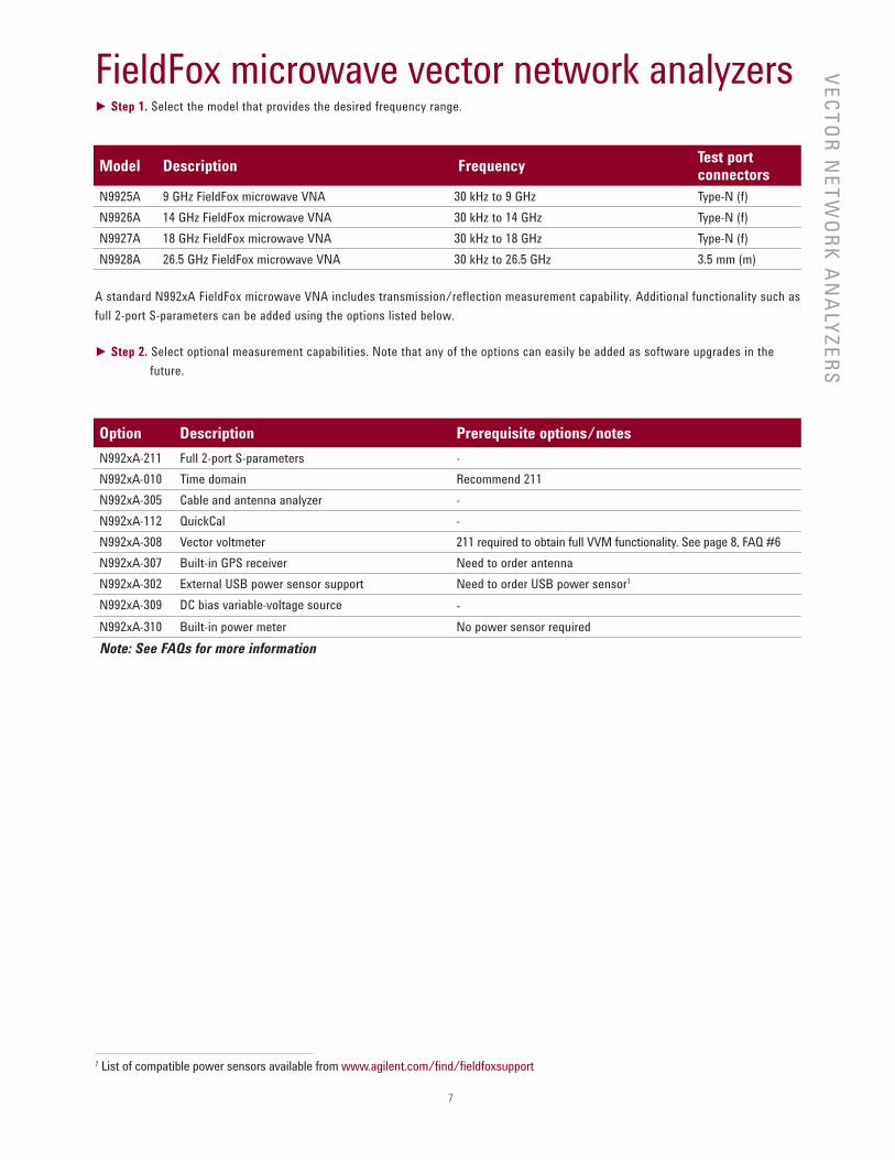
FieldFox microwave vector network analyzers► Step 1. Select the model that provides the desired frequency range.
Model Description Frequency Test port connectors
N9925A 9 GHz FieldFox microwave VNA 30 kHz to 9 GHz Type-N (f)
N9926A 14 GHz FieldFox microwave VNA 30 kHz to 14 GHz Type-N (f)
N9927A 18 GHz FieldFox microwave VNA 30 kHz to 18 GHz Type-N (f)
N9928A 26.5 GHz FieldFox microwave VNA 30 kHz to 26.5 GHz 3.5 mm (m)
A standard N992xA FieldFox microwave VNA includes transmission/reflection measurement capability. Additional functionality such as
full 2-port S-parameters can be added using the options listed below.
► Step 2. Select optional measurement capabilities. Note that any of the options can easily be added as software upgrades in the
future.
Option Description Prerequisite options/notes
N992xA-211 Full 2-port S-parameters -
N992xA-010 Time domain Recommend 211
N992xA-305 Cable and antenna analyzer -
N992xA-112 QuickCal -
N992xA-308 Vector voltmeter 211 required to obtain full VVM functionality. See page 8, FAQ #6
N992xA-307 Built-in GPS receiver Need to order antenna
N992xA-302 External USB power sensor support Need to order USB power sensor1
N992xA-309 DC bias variable-voltage source -
N992xA-310 Built-in power meter No power sensor required
Note: See FAQs for more information
VE
CT
OR
NE
TW
OR
K A
NA
LYZ
ER
S
1 List of compatible power sensors available from www.agilent.com/find/fieldfoxsupport
8
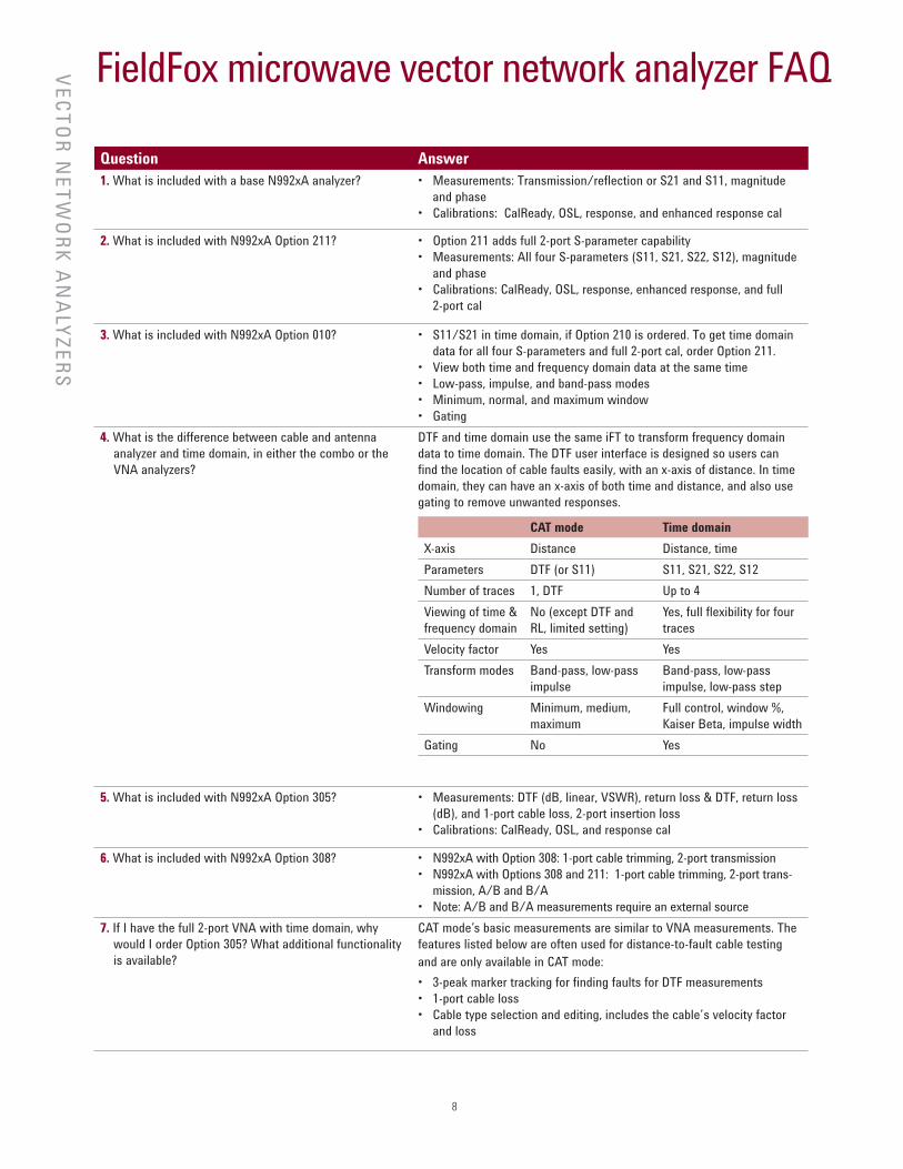
FieldFox microwave vector network analyzer FAQ
Question Answer
1. What is included with a base N992xA analyzer? • Measurements: Transmission/reflection or S21 and S11, magnitude
and phase
• Calibrations: CalReady, OSL, response, and enhanced response cal
2. What is included with N992xA Option 211? • Option 211 adds full 2-port S-parameter capability
• Measurements: All four S-parameters (S11, S21, S22, S12), magnitude
and phase
• Calibrations: CalReady, OSL, response, enhanced response, and full
2-port cal
3. What is included with N992xA Option 010? • S11/S21 in time domain, if Option 210 is ordered. To get time domain
data for all four S-parameters and full 2-port cal, order Option 211.
• View both time and frequency domain data at the same time
• Low-pass, impulse, and band-pass modes
• Minimum, normal, and maximum window
• Gating
4. What is the difference between cable and antenna
analyzer and time domain, in either the combo or the
VNA analyzers?
DTF and time domain use the same iFT to transform frequency domain
data to time domain. The DTF user interface is designed so users can
find the location of cable faults easily, with an x-axis of distance. In time
domain, they can have an x-axis of both time and distance, and also use
gating to remove unwanted responses.
5. What is included with N992xA Option 305? • Measurements: DTF (dB, linear, VSWR), return loss & DTF, return loss
(dB), and 1-port cable loss, 2-port insertion loss
• Calibrations: CalReady, OSL, and response cal
6. What is included with N992xA Option 308? • N992xA with Option 308: 1-port cable trimming, 2-port transmission
• N992xA with Options 308 and 211: 1-port cable trimming, 2-port trans-
mission, A/B and B/A
• Note: A/B and B/A measurements require an external source
7. If I have the full 2-port VNA with time domain, why
would I order Option 305? What additional functionality
is available?
CAT mode’s basic measurements are similar to VNA measurements. The
features listed below are often used for distance-to-fault cable testing
and are only available in CAT mode:
• 3-peak marker tracking for finding faults for DTF measurements
• 1-port cable loss
• Cable type selection and editing, includes the cable’s velocity factor
and loss
CAT mode Time domain
X-axis Distance Distance, time
Parameters DTF (or S11) S11, S21, S22, S12
Number of traces 1, DTF Up to 4
Viewing of time &
frequency domain
No (except DTF and
RL, limited setting)
Yes, full flexibility for four
traces
Velocity factor Yes Yes
Transform modes Band-pass, low-pass
impulse
Band-pass, low-pass
impulse, low-pass step
Windowing Minimum, medium,
maximum
Full control, window %,
Kaiser Beta, impulse width
Gating No Yes
VE
CT
OR
NE
TW
OR
K A
NA
LYZ
ER
S
9
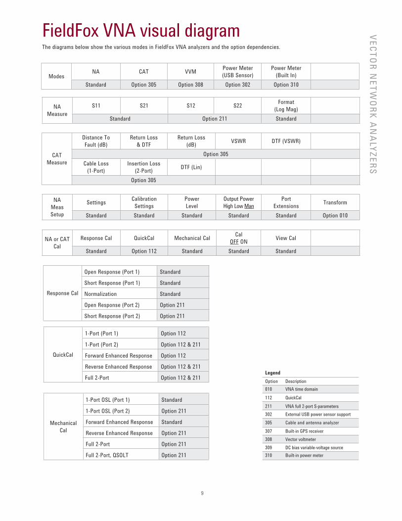
FieldFox VNA visual diagramThe diagrams below show the various modes in FieldFox VNA analyzers and the option dependencies.
VE
CT
OR
NE
TW
OR
K A
NA
LYZ
ER
S
ModesNA CAT VVM
Power Meter
(USB Sensor)
Power Meter
(Built In)
Standard Option 305 Option 308 Option 302 Option 310
CAT
Measure
Distance To
Fault (dB)
Return Loss
& DTF
Return Loss
(dB)VSWR DTF (VSWR)
Option 305
Cable Loss
(1-Port)
Insertion Loss
(2-Port)DTF (Lin)
Option 305
NA
Measure
S11 S21 S12 S22Format
(Log Mag)
Standard Option 211 Standard
Response Cal
Open Response (Port 1) Standard
Short Response (Port 1) Standard
Normalization Standard
Open Response (Port 2) Option 211
Short Response (Port 2) Option 211
QuickCal
1-Port (Port 1) Option 112
1-Port (Port 2) Option 112 & 211
Forward Enhanced Response Option 112
Reverse Enhanced Response Option 112 & 211
Full 2-Port Option 112 & 211
Mechanical
Cal
1-Port OSL (Port 1) Standard
1-Port OSL (Port 2) Option 211
Forward Enhanced Response Standard
Reverse Enhanced Response Option 211
Full 2-Port Option 211
Full 2-Port, QSOLT Option 211
NA
Meas
Setup
SettingsCalibration
Settings
Power
Level
Output Power
High Low Man
Port
ExtensionsTransform
Standard Standard Standard Standard Standard Option 010
NA or CAT
Cal
Response Cal QuickCal Mechanical CalCal
OFF ONView Cal
Standard Option 112 Standard Standard Standard
Legend
Option Description
010 VNA time domain
112 QuickCal
211 VNA full 2-port S-parameters
302 External USB power sensor support
305 Cable and antenna analyzer
307 Built-in GPS receiver
308 Vector voltmeter
309 DC bias variable-voltage source
310 Built-in power meter
10
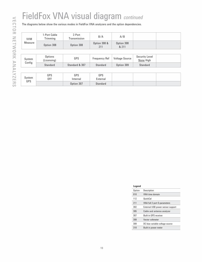
FieldFox VNA visual diagram continuedThe diagrams below show the various modes in FieldFox VNA analyzers and the option dependencies.
VVM
Measure
1-Port Cable
Trimming
2-Port
TransmissionB/A A/B
Option 308 Option 308Option 308 &
211
Option 308
& 211
System
Config
Options
(Licensing)GPS Frequency Ref Voltage Source
Security Level
None High
Standard Standard & 307 Standard Option 309 Standard
System
GPS
GPS
OFF
GPS
Internal
GPS
External
Option 307 Standard
VE
CT
OR
NE
TW
OR
K A
NA
LYZ
ER
SLegend
Option Description
010 VNA time domain
112 QuickCal
211 VNA full 2-port S-parameters
302 External USB power sensor support
305 Cable and antenna analyzer
307 Built-in GPS receiver
308 Vector voltmeter
309 DC bias variable-voltage source
310 Built-in power meter
11
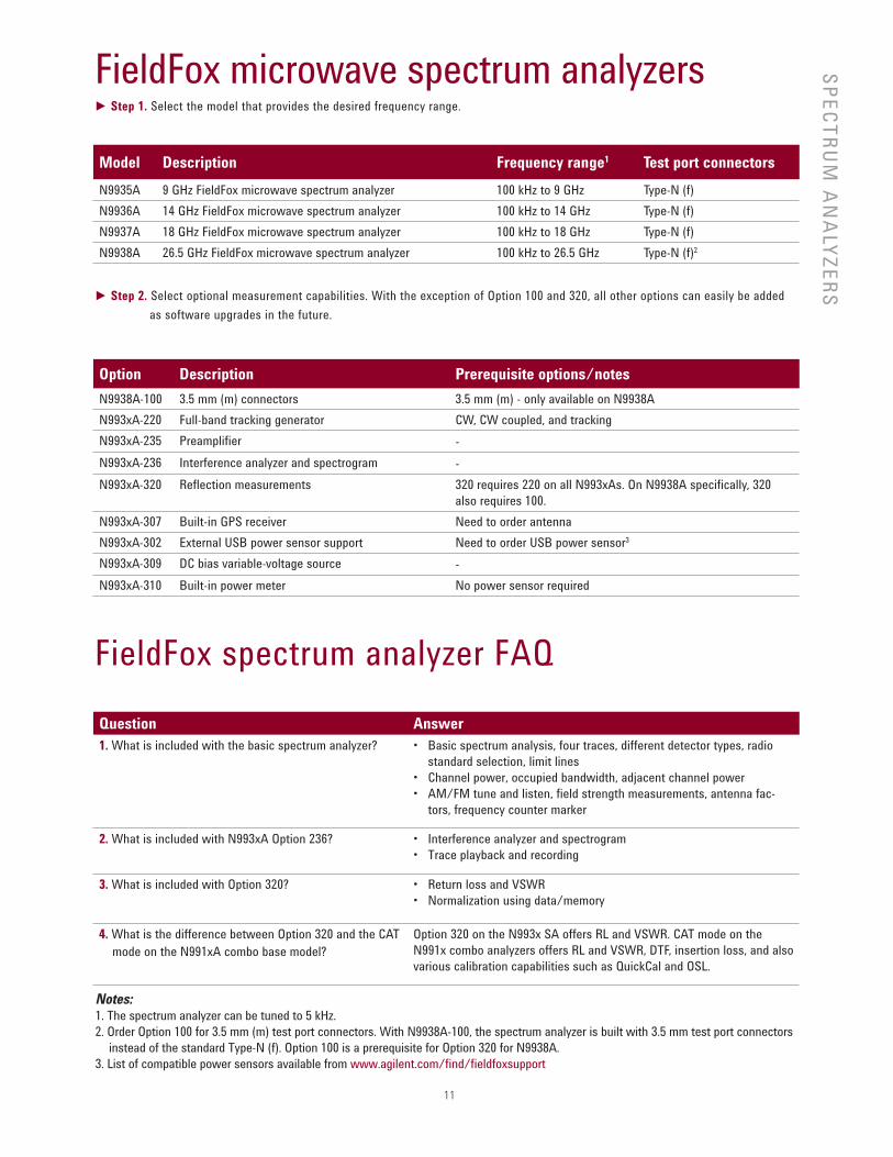
FieldFox microwave spectrum analyzers► Step 1. Select the model that provides the desired frequency range.
Model Description Frequency range1 Test port connectors
N9935A 9 GHz FieldFox microwave spectrum analyzer 100 kHz to 9 GHz Type-N (f)
N9936A 14 GHz FieldFox microwave spectrum analyzer 100 kHz to 14 GHz Type-N (f)
N9937A 18 GHz FieldFox microwave spectrum analyzer 100 kHz to 18 GHz Type-N (f)
N9938A 26.5 GHz FieldFox microwave spectrum analyzer 100 kHz to 26.5 GHz Type-N (f)2
► Step 2. Select optional measurement capabilities. With the exception of Option 100 and 320, all other options can easily be added
as software upgrades in the future.
Option Description Prerequisite options/notes
N9938A-100 3.5 mm (m) connectors 3.5 mm (m) - only available on N9938A
N993xA-220 Full-band tracking generator CW, CW coupled, and tracking
N993xA-235 Preamplifier -
N993xA-236 Interference analyzer and spectrogram -
N993xA-320 Reflection measurements 320 requires 220 on all N993xAs. On N9938A specifically, 320
also requires 100.
N993xA-307 Built-in GPS receiver Need to order antenna
N993xA-302 External USB power sensor support Need to order USB power sensor3
N993xA-309 DC bias variable-voltage source -
N993xA-310 Built-in power meter No power sensor required
FieldFox spectrum analyzer FAQ
Question Answer
1. What is included with the basic spectrum analyzer? • Basic spectrum analysis, four traces, different detector types, radio
standard selection, limit lines
• Channel power, occupied bandwidth, adjacent channel power
• AM/FM tune and listen, field strength measurements, antenna fac-
tors, frequency counter marker
2. What is included with N993xA Option 236? • Interference analyzer and spectrogram
• Trace playback and recording
3. What is included with Option 320? • Return loss and VSWR
• Normalization using data/memory
4. What is the difference between Option 320 and the CAT
mode on the N991xA combo base model?
Option 320 on the N993x SA offers RL and VSWR. CAT mode on the
N991x combo analyzers offers RL and VSWR, DTF, insertion loss, and also
various calibration capabilities such as QuickCal and OSL.
Notes:1. The spectrum analyzer can be tuned to 5 kHz.
2. Order Option 100 for 3.5 mm (m) test port connectors. With N9938A-100, the spectrum analyzer is built with 3.5 mm test port connectors
instead of the standard Type-N (f). Option 100 is a prerequisite for Option 320 for N9938A.
3. List of compatible power sensors available from www.agilent.com/fi nd/fi eldfoxsupport
SP
EC
TR
UM
AN
ALY
ZE
RS
12
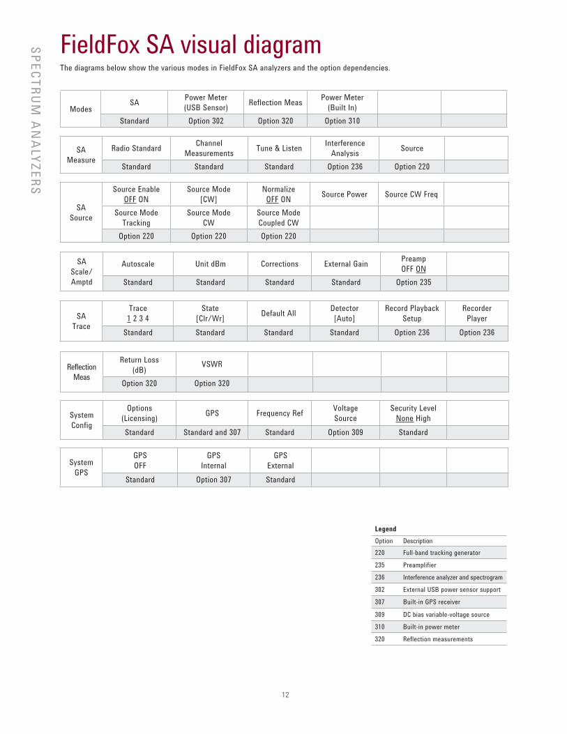
FieldFox SA visual diagramThe diagrams below show the various modes in FieldFox SA analyzers and the option dependencies.
ModesSA
Power Meter
(USB Sensor)Reflection Meas
Power Meter
(Built In)
Standard Option 302 Option 320 Option 310
SA
Measure
Radio StandardChannel
MeasurementsTune & Listen
Interference
AnalysisSource
Standard Standard Standard Option 236 Option 220
SA
Scale/
Amptd
Autoscale Unit dBm Corrections External GainPreamp
OFF ON
Standard Standard Standard Standard Option 235
SA
Source
Source Enable
OFF ON
Source Mode
[CW]
Normalize
OFF ONSource Power Source CW Freq
Source Mode
Tracking
Source Mode
CW
Source Mode
Coupled CW
Option 220 Option 220 Option 220
SA
Trace
Trace
1 2 3 4
State
[Clr/Wr]Default All
Detector
[Auto]
Record Playback
Setup
Recorder
Player
Standard Standard Standard Standard Option 236 Option 236
System
Config
Options
(Licensing)GPS Frequency Ref
Voltage
Source
Security Level
None High
Standard Standard and 307 Standard Option 309 Standard
System
GPS
GPS
OFF
GPS
Internal
GPS
External
Standard Option 307 Standard
SP
EC
TR
UM
AN
ALY
ZE
RS
Reflection
Meas
Return Loss
(dB)VSWR
Option 320 Option 320
Legend
Option Description
220 Full-band tracking generator
235 Preamplifier
236 Interference analyzer and spectrogram
302 External USB power sensor support
307 Built-in GPS receiver
309 DC bias variable-voltage source
310 Built-in power meter
320 Reflection measurements

13
FAQ – Applicable to all FieldFox microwave analyzersQuestion Answer
1. What USB power sensors
work with Option 302?
All Agilent U2000x Series USB power sensors are supported with FieldFox.
Visit: www.agilent.com/find/fieldfoxsupport for an up-to-date listing.
2. What is the difference
between USB power sensor
(Option 302) and built-in
power meter (Option 310)?
Option 302
USB powers sensor
Option 310
Built-in power meter (or channel power meter)
Description Option 302 allows users to connect a USB
power sensor to FieldFox’s USB port and
make broadband power measurements.
Option 310 is a channelized power measurement capabil-
ity built into FieldFox analyzers. Maximum bandwidth is
100 MHz.
External hardware U2000x power sensor required None. Uses internal receiver.
Power measurement Broadband diode detector, measures all
frequencies
Tuned receiver, so measures frequencies within defined
channel bandwidth
Frequency range Depends on USB sensor Frequency range of the analyzer
Settings Set CW frequency Set CW frequency, Set channel width/span
Power range Depends on USB sensor Depends on channel width and attenuator setting.
Warm-up time 30 minutes to meet accuracy specifica-
tions
No warm-up time required
Accuracy Depends on USB sensor InstAlign accuracy: ± 0.5 dB typical for a CW signal.
Since the measurement is within a certain frequency
channel or bandwidth, to make an accurate measure-
ment, the user needs to know the exact center frequency
and the signal’s characteristics and set those accurately.
Programmable Yes, via SCPI No
Physical connection The power sensor can easily be moved to
the measurement point, with a USB cable
connecting the detector to FieldFox.
The measurement point needs to be connected to
FieldFox’s RF input port. If a RF jumper cable is used, the
user needs to account for the loss of the cable with an
offset value (can be entered into the analyzer).
14
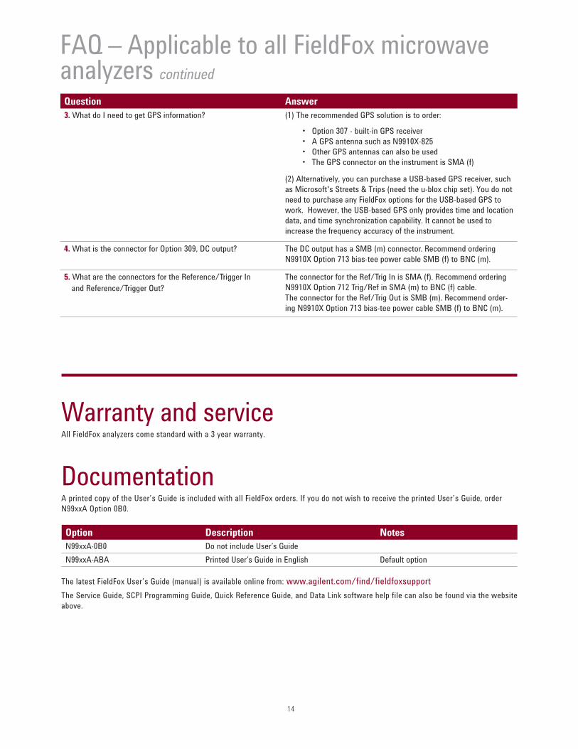
Warranty and service All FieldFox analyzers come standard with a 3 year warranty.
Documentation A printed copy of the User’s Guide is included with all FieldFox orders. If you do not wish to receive the printed User’s Guide, order
N99xxA Option 0B0.
The latest FieldFox User’s Guide (manual) is available online from: www.agilent.com/find/fieldfoxsupport
The Service Guide, SCPI Programming Guide, Quick Reference Guide, and Data Link software help file can also be found via the website
above.
Option Description Notes
N99xxA-0B0 Do not include User’s Guide
N99xxA-ABA Printed User’s Guide in English Default option
FAQ – Applicable to all FieldFox microwave analyzers continuedQuestion Answer
3. What do I need to get GPS information? (1) The recommended GPS solution is to order:
• Option 307 - built-in GPS receiver
• A GPS antenna such as N9910X-825
• Other GPS antennas can also be used
• The GPS connector on the instrument is SMA (f)
(2) Alternatively, you can purchase a USB-based GPS receiver, such
as Microsoft's Streets & Trips (need the u-blox chip set). You do not
need to purchase any FieldFox options for the USB-based GPS to
work. However, the USB-based GPS only provides time and location
data, and time synchronization capability. It cannot be used to
increase the frequency accuracy of the instrument.
4. What is the connector for Option 309, DC output? The DC output has a SMB (m) connector. Recommend ordering
N9910X Option 713 bias-tee power cable SMB (f) to BNC (m).
5. What are the connectors for the Reference/Trigger In
and Reference/Trigger Out?
The connector for the Ref/Trig In is SMA (f). Recommend ordering
N9910X Option 712 Trig/Ref in SMA (m) to BNC (f) cable.
The connector for the Ref/Trig Out is SMB (m). Recommend order-
ing N9910X Option 713 bias-tee power cable SMB (f) to BNC (m).
15
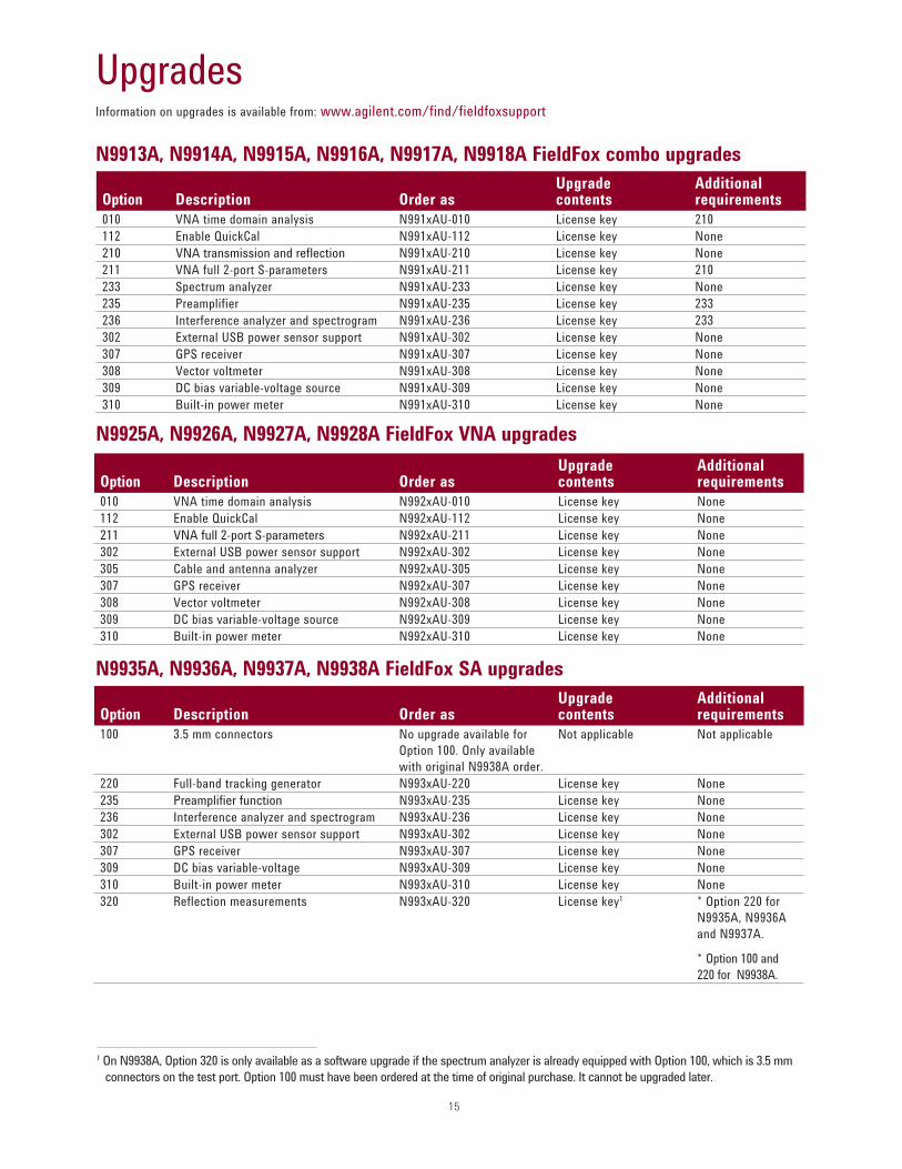
UpgradesInformation on upgrades is available from: www.agilent.com/find/fieldfoxsupport
N9913A, N9914A, N9915A, N9916A, N9917A, N9918A FieldFox combo upgrades
Option Description Order asUpgrade contents
Additional requirements
010 VNA time domain analysis N991xAU-010 License key 210
112 Enable QuickCal N991xAU-112 License key None
210 VNA transmission and refl ection N991xAU-210 License key None
211 VNA full 2-port S-parameters N991xAU-211 License key 210
233 Spectrum analyzer N991xAU-233 License key None
235 Preamplifier N991xAU-235 License key 233
236 Interference analyzer and spectrogram N991xAU-236 License key 233
302 External USB power sensor support N991xAU-302 License key None
307 GPS receiver N991xAU-307 License key None
308 Vector voltmeter N991xAU-308 License key None
309 DC bias variable-voltage source N991xAU-309 License key None
310 Built-in power meter N991xAU-310 License key None
N9925A, N9926A, N9927A, N9928A FieldFox VNA upgrades
Option Description Order asUpgrade contents
Additional requirements
010 VNA time domain analysis N992xAU-010 License key None
112 Enable QuickCal N992xAU-112 License key None
211 VNA full 2-port S-parameters N992xAU-211 License key None
302 External USB power sensor support N992xAU-302 License key None
305 Cable and antenna analyzer N992xAU-305 License key None
307 GPS receiver N992xAU-307 License key None
308 Vector voltmeter N992xAU-308 License key None
309 DC bias variable-voltage source N992xAU-309 License key None
310 Built-in power meter N992xAU-310 License key None
N9935A, N9936A, N9937A, N9938A FieldFox SA upgrades
Option Description Order asUpgrade contents
Additional requirements
100 3.5 mm connectors No upgrade available for
Option 100. Only available
with original N9938A order.
Not applicable Not applicable
220 Full-band tracking generator N993xAU-220 License key None
235 Preamplifi er function N993xAU-235 License key None
236 Interference analyzer and spectrogram N993xAU-236 License key None
302 External USB power sensor support N993xAU-302 License key None
307 GPS receiver N993xAU-307 License key None
309 DC bias variable-voltage N993xAU-309 License key None
310 Built-in power meter N993xAU-310 License key None
320 Reflection measurements N993xAU-320 License key1 * Option 220 for
N9935A, N9936A
and N9937A.
* Option 100 and
220 for N9938A.
1 On N9938A, Option 320 is only available as a software upgrade if the spectrum analyzer is already equipped with Option 100, which is 3.5 mm
connectors on the test port. Option 100 must have been ordered at the time of original purchase. It cannot be upgraded later.
16
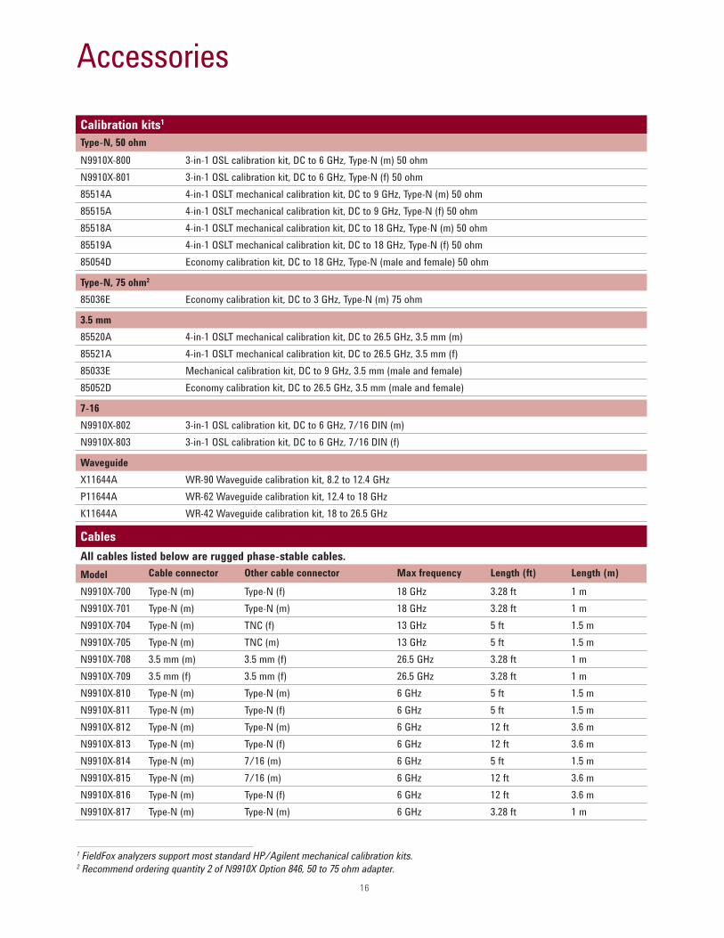
Accessories
Calibration kits1
Type-N, 50 ohm
N9910X-800 3-in-1 OSL calibration kit, DC to 6 GHz, Type-N (m) 50 ohm
N9910X-801 3-in-1 OSL calibration kit, DC to 6 GHz, Type-N (f) 50 ohm
85514A 4-in-1 OSLT mechanical calibration kit, DC to 9 GHz, Type-N (m) 50 ohm
85515A 4-in-1 OSLT mechanical calibration kit, DC to 9 GHz, Type-N (f) 50 ohm
85518A 4-in-1 OSLT mechanical calibration kit, DC to 18 GHz, Type-N (m) 50 ohm
85519A 4-in-1 OSLT mechanical calibration kit, DC to 18 GHz, Type-N (f) 50 ohm
85054D Economy calibration kit, DC to 18 GHz, Type-N (male and female) 50 ohm
Type-N, 75 ohm2
85036E Economy calibration kit, DC to 3 GHz, Type-N (m) 75 ohm
3.5 mm
85520A 4-in-1 OSLT mechanical calibration kit, DC to 26.5 GHz, 3.5 mm (m)
85521A 4-in-1 OSLT mechanical calibration kit, DC to 26.5 GHz, 3.5 mm (f)
85033E Mechanical calibration kit, DC to 9 GHz, 3.5 mm (male and female)
85052D Economy calibration kit, DC to 26.5 GHz, 3.5 mm (male and female)
7-16
N9910X-802 3-in-1 OSL calibration kit, DC to 6 GHz, 7/16 DIN (m)
N9910X-803 3-in-1 OSL calibration kit, DC to 6 GHz, 7/16 DIN (f)
Waveguide
X11644A WR-90 Waveguide calibration kit, 8.2 to 12.4 GHz
P11644A WR-62 Waveguide calibration kit, 12.4 to 18 GHz
K11644A WR-42 Waveguide calibration kit, 18 to 26.5 GHz
Cables
All cables listed below are rugged phase-stable cables.
1 FieldFox analyzers support most standard HP/Agilent mechanical calibration kits. 2 Recommend ordering quantity 2 of N9910X Option 846, 50 to 75 ohm adapter.
Model Cable connector Other cable connector Max frequency Length (ft) Length (m)
N9910X-700 Type-N (m) Type-N (f) 18 GHz 3.28 ft 1 m
N9910X-701 Type-N (m) Type-N (m) 18 GHz 3.28 ft 1 m
N9910X-704 Type-N (m) TNC (f) 13 GHz 5 ft 1.5 m
N9910X-705 Type-N (m) TNC (m) 13 GHz 5 ft 1.5 m
N9910X-708 3.5 mm (m) 3.5 mm (f) 26.5 GHz 3.28 ft 1 m
N9910X-709 3.5 mm (f) 3.5 mm (f) 26.5 GHz 3.28 ft 1 m
N9910X-810 Type-N (m) Type-N (m) 6 GHz 5 ft 1.5 m
N9910X-811 Type-N (m) Type-N (f) 6 GHz 5 ft 1.5 m
N9910X-812 Type-N (m) Type-N (m) 6 GHz 12 ft 3.6 m
N9910X-813 Type-N (m) Type-N (f) 6 GHz 12 ft 3.6 m
N9910X-814 Type-N (m) 7/16 (m) 6 GHz 5 ft 1.5 m
N9910X-815 Type-N (m) 7/16 (m) 6 GHz 12 ft 3.6 m
N9910X-816 Type-N (m) Type-N (f) 6 GHz 12 ft 3.6 m
N9910X-817 Type-N (m) Type-N (m) 6 GHz 3.28 ft 1 m
17
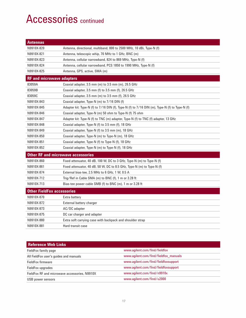
Accessories continued
Antennas
N9910X-820 Antenna, directional, multiband, 800 to 2500 MHz, 10 dBi, Type-N (f)
N9910X-821 Antenna, telescopic whip, 70 MHz to 1 GHz, BNC (m)
N9910X-823 Antenna, cellular narrowband, 824 to 869 MHz, Type-N (f)
N9910X-824 Antenna, cellular narrowband, PCS 1850 to 1990 MHz, Type-N (f)
N9910X-825 Antenna, GPS, active, SMA (m)
RF and microwave adapters
83059A Coaxial adapter, 3.5 mm (m) to 3.5 mm (m), 26.5 GHz
83059B Coaxial adapter, 3.5 mm (f) to 3.5 mm (f), 26.5 GHz
83059C Coaxial adapter, 3.5 mm (m) to 3.5 mm (f), 26.5 GHz
N9910X-843 Coaxial adapter, Type-N (m) to 7/16 DIN (f)
N9910X-845 Adapter kit: Type-N (f) to 7/16 DIN (f), Type-N (f) to 7/16 DIN (m), Type-N (f) to Type-N (f)
N9910X-846 Coaxial adapter, Type-N (m) 50 ohm to Type-N (f) 75 ohm
N9910X-847 Adapter kit: Type-N (f) to TNC (m) adapter, Type-N (f) to TNC (f) adapter, 13 GHz
N9910X-848 Coaxial adapter, Type-N (f) to 3.5 mm (f), 18 GHz
N9910X-849 Coaxial adapter, Type-N (f) to 3.5 mm (m), 18 GHz
N9910X-850 Coaxial adapter, Type-N (m) to Type-N (m), 18 GHz
N9910X-851 Coaxial adapter, Type-N (f) to Type-N (f), 18 GHz
N9910X-852 Coaxial adapter, Type-N (m) to Type-N (f), 18 GHz
Other RF and microwave accessories
N9910X-860 Fixed attenuator, 40 dB, 100 W, DC to 3 GHz, Type-N (m) to Type-N (f)
N9910X-861 Fixed attenuator, 40 dB, 50 W, DC to 8.5 GHz, Type-N (m) to Type-N (f)
N9910X-874 External bias-tee, 2.5 MHz to 6 GHz, 1 W, 0.5 A
N9910X-712 Trig/Ref in Cable SMA (m) to BNC (f), 1 m or 3.28 ft
N9910X-713 Bias-tee power cable SMB (f) to BNC (m), 1 m or 3.28 ft
Other FieldFox accessories
N9910X-870 Extra battery
N9910X-872 External battery charger
N9910X-873 AC/DC adapter
N9910X-875 DC car charger and adapter
N9910X-880 Extra soft carrying case with backpack and shoulder strap
N9910X-881 Hard transit case
Reference Web Links
FieldFox family page
All FieldFox user's guides and manuals
FieldFox firmware
FieldFox upgrades
FieldFox RF and microwave accessories, N9910X
USB power sensors
www.agilent.com/find/fieldfox
www.agilent.com/find/fieldfox_manuals
www.agilent.com/find/fieldfoxsupport
www.agilent.com/find/fieldfoxsupport
www.agilent.com/find/n9910x
www.agilent.com/find/u2000
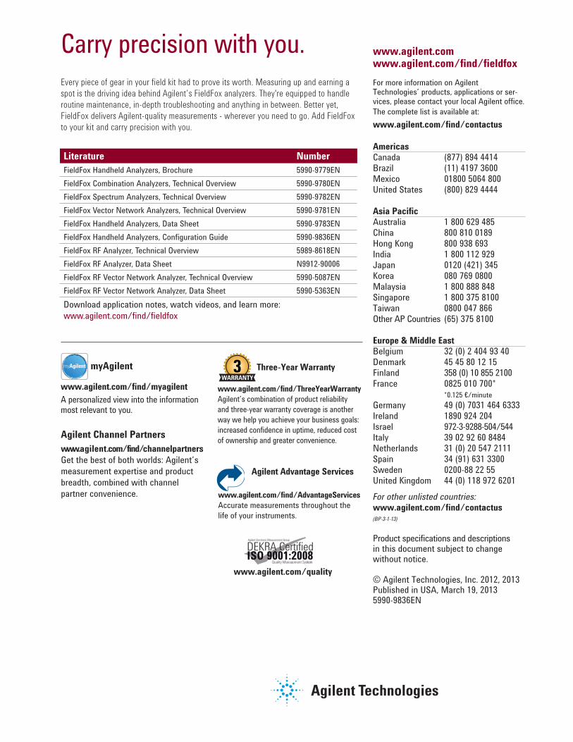
For more information on Agilent Technologies’ products, applications or ser-vices, please contact your local Agilent office.
The complete list is available at:
www.agilent.com/find/contactus
AmericasCanada (877) 894 4414 Brazil (11) 4197 3600Mexico 01800 5064 800 United States (800) 829 4444
Asia PacificAustralia 1 800 629 485China 800 810 0189Hong Kong 800 938 693India 1 800 112 929Japan 0120 (421) 345Korea 080 769 0800Malaysia 1 800 888 848Singapore 1 800 375 8100Taiwan 0800 047 866Other AP Countries (65) 375 8100
Europe & Middle EastBelgium 32 (0) 2 404 93 40 Denmark 45 45 80 12 15Finland 358 (0) 10 855 2100France 0825 010 700* *0.125 €/minute
Germany 49 (0) 7031 464 6333 Ireland 1890 924 204Israel 972-3-9288-504/544Italy 39 02 92 60 8484Netherlands 31 (0) 20 547 2111Spain 34 (91) 631 3300Sweden 0200-88 22 55United Kingdom 44 (0) 118 972 6201
For other unlisted countries: www.agilent.com/find/contactus(BP-3-1-13)
Product specifications and descriptions in this document subject to change without notice.
© Agilent Technologies, Inc. 2012, 2013Published in USA, March 19, 20135990-9836EN
Literature Number
FieldFox Handheld Analyzers, Brochure 5990-9779EN
FieldFox Combination Analyzers, Technical Overview 5990-9780EN
FieldFox Spectrum Analyzers, Technical Overview 5990-9782EN
FieldFox Vector Network Analyzers, Technical Overview 5990-9781EN
FieldFox Handheld Analyzers, Data Sheet 5990-9783EN
FieldFox Handheld Analyzers, Configuration Guide 5990-9836EN
FieldFox RF Analyzer, Technical Overview 5989-8618EN
FieldFox RF Analyzer, Data Sheet N9912-90006
FieldFox RF Vector Network Analyzer, Technical Overview 5990-5087EN
FieldFox RF Vector Network Analyzer, Data Sheet 5990-5363EN
Download application notes, watch videos, and learn more:
www.agilent.com/find/fieldfox
Carry precision with you. Every piece of gear in your field kit had to prove its worth. Measuring up and earning a
spot is the driving idea behind Agilent’s FieldFox analyzers. They're equipped to handle
routine maintenance, in-depth troubleshooting and anything in between. Better yet,
FieldFox delivers Agilent-quality measurements - wherever you need to go. Add FieldFox
to your kit and carry precision with you.
Agilent Channel Partners
www.agilent.com/find/channelpartners
Get the best of both worlds: Agilent’s
measurement expertise and product
breadth, combined with channel
partner convenience.
www.agilent.com/find/myagilent
A personalized view into the information most relevant to you.
myAgilentmyAgilent
www.agilent.com/quality
Quality Management SystemQuality Management SysISO 9001:2008
Agilent Electronic Measurement Group
DEKRA Certified
www.agilent.com/find/AdvantageServices
Accurate measurements throughout the
life of your instruments.
Agilent Advantage Services
Three-Year Warranty
www.agilent.com/find/ThreeYearWarranty
Agilent’s combination of product reliability
and three-year warranty coverage is another
way we help you achieve your business goals:
increased confidence in uptime, reduced cost
of ownership and greater convenience.
www.agilent.comwww.agilent.com/find/fieldfox