advanced(medical(image( analysis(
TRANSCRIPT

Advanced Medical Image Analysis
Fall 2012 Lecture 11 – Surface and Volume Meshing
Michel Aude<e, Ph.D. Old Dominion University
Dept. Modeling, SimulaFon and VisualizaFon Engineering

Why this is cool – surface and volume meshing
• Generally speaking, segmentaFon gives us either a voxel-‐based volume, or its boundary.
• For biomedical simulaFon, we need to break down Fssues into simple shapes -‐ triangles or tetrahedra.
MR/CT Tissue map Polygonalize tissue boundary
Insert inner vertices Simulation
BACKGROUND – MEDICAL SIMULATION
3

InteracFve vs predicFve simulaFon
• Surgical simulaAon: synthesize Fssue response to surgical acFon
• Predic)ve: high-‐quality offline (FE) simulaFons for experts. • Interac)ve: real-‐Fme response to hapFc gesture for residents.
• Research: reconcile predic've with interac've biomechanics.
Images reproduced from M. Chabanas, Université de Grenoble, S. Cotin, INRIA, Wikimedia Commons, and ixbtlabs.com

InteracFve simulaFon – h/w architecture
• HapFc interacFon: 2-‐way device – 200 Hz+ – Angles to posiFon by forward kinemaFcs.
– Force to joint torques by inverse Jacobian transformaFon.
• Visual interacFon: monitor

InteracFve simulaFon – s/w architecture
• Anatomical model, typically composed of tetrahedra, encapsulaFng the anatomy over simulated Fme;
• Biomechanics engine that synthesizes a Fssue response to a virtual gesture;
• Collision detecAon algorithm that efficiently determines where the interacFon takes place;
• Engines dedicated to hapAc and visual rendering.

Surgery simulaFon – biomechanics
• Trade-‐off between speed vs cons)tu)ve fidelity.
• InteracFve simulaFon tradiFonally emphasizes interac)vity at expense of fidelity to Fssue biomechanics.
• Predic)ve simula)on for expert surgeons places emphasis on fidelity – need not be interacFve.
speed fidelity
Mass-springs Finite elements
TLED FE MJED FE
Multi-grid FE

Surgery simulaFon – biomechanics (2)
•

Surgery simulaFon – biomechanics (3)
•

Surgery simulaFon – biomechanics (5)
• Emerging soluFons for interacFve simulaFon. • PrecomputaFons: derivaFves via undeformed coordinates:
– Total Lagrangian Explicit Dynamics (explicit) – MulFplicaFve Jacobian Energy DecomposiFon (implicit)
• MulF-‐grid: coarse FE helping medium and fine FE systems to converge more quickly.
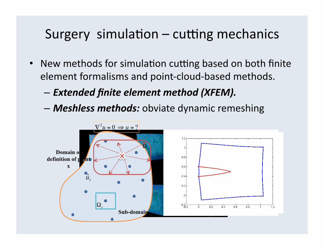
Surgery simulaFon – cubng mechanics
• New methods for simulaFon cubng based on both finite element formalisms and point-‐cloud-‐based methods.
– Extended finite element method (XFEM).
– Meshless methods: obviate dynamic remeshing
Sub-domain
Domain of definition of point
x
IMPLICATIONS FOR MESHING
12

Tetrahedral meshing implicaFons -‐ resoluFon
• Importance of mesh resoluAon: – We care about resolu)on, especially for interacFve simulaFon: solving 2K tets quicker than 20K, 200K tets.
– Mul)-‐grid FE impossible w/o coarse/medium/fine tets.
– Also, no need to mesh whole volume at medium & fine resoluFons – target and path to target only.

Tet. meshing implicaFons – Quality (1)
• Importance of mesh quality: – We care about element quality, for fast convergence: slivers (flat tets) lead to slow/unstable soluFon.
– Quality of an element: absence of…
• edges of small size (vs. other edges), and • small dihedral angles (angle between two planes).
Sliver: near-complanar tet
High-quality tetrahedron
Various near-degenerate tets.
Jane Tournois1, Rahul Srinivasan2, and Pierre Alliez1 - Perturbing Slivers in 3D Delaunay Meshes

Tet. meshing implicaFons – Quality (2)
• FE convergence – based on condi)on number of sFffness matrix K;
• K composed of elemental sFffnesses Ke
• Ke is a funcFon of dihedral angles and edge lengths
Tet. meshing implicaFons – Quality (3)
•

Tet. meshing implicaFons – Quality (4)
• Measure of tet mesh quality: histogram of dihedral angles • B. Klingner (Berkley): Aggressive Tet Mesh Improvement

Tet. meshing implicaFons – ResoluFon and Quality
•

What kind of element to use?
• Q: Is tet meshing always desirable? E.g: cranial nerve • Consider 20mm segment between points A and B.
• Volume = 20 mm x Π x (0.5 mm)2 = 15.7 mm3 ≈ 1056 tets (0.5mm edges)
• Or… piecewise-‐linear beam element ≈ 6 elements.
A B

MESH GENERATION
20

Structured vs Unstructured Mesh GeneraFon
• Structured meshing: quadrilateral and hexahedral meshing in 2D and 3D respecFvely;
– Interior nodes: constant number of incident elements.
– Manual interacFon of user to produce a template &
procedure for warping this template to pa)ent data.
Orthopedic applications of structured meshing, courtesy of N. Grosland (Univ. Iowa)/

Structured vs Unstructured Mesh GeneraFon (2)
• Unstructured mesh genera)on:
– relaxes node valence requirement: any number of elements can meet at a given node.
– Minimally supervised methods feasible.
– Four categories: • Octree-‐based • Delaunay • Advancing Front • OpAmizaAon-‐based

Unstructured Mesh GeneraFon – Basic idea
• Workflow: i) inserFon of nodes w or w/o boundaries ii) link neighboring nodes by edges
iii) assemble edges into faces, faces into tets.

Octree-‐based Unstructured Mesh GeneraFon
• Recursive subdivision of Fssue volume into conFguous cubes fully or parFally overlapped by this Fssue.
• Irregular cells are created where the cubes intersect the boundary of the volume, which typically requires a large number of surface intersecFon computaFons.
Octree-‐based Unstructured Mesh GeneraFon (2)
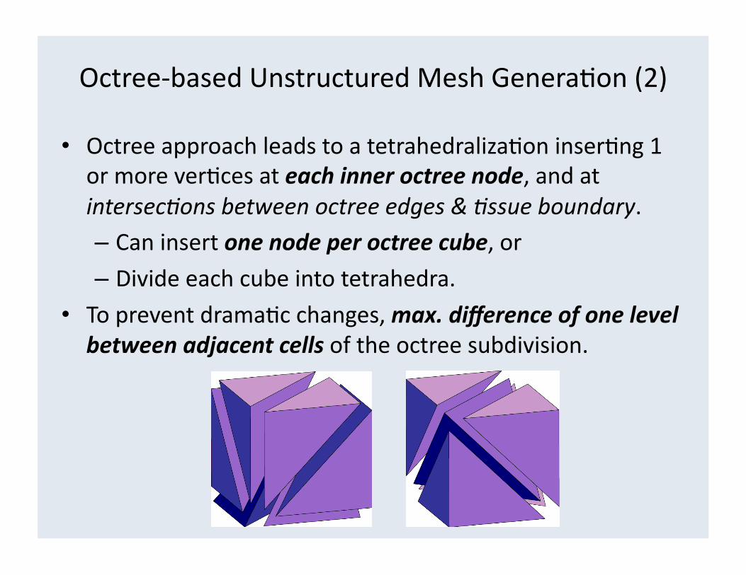
• Octree approach leads to a tetrahedralizaFon inserFng 1 or more verFces at each inner octree node, and at intersec'ons between octree edges & 'ssue boundary. – Can insert one node per octree cube, or – Divide each cube into tetrahedra.
• To prevent dramaFc changes, max. difference of one level between adjacent cells of the octree subdivision.

Octree-‐based Unstructured Mesh GeneraFon (2)
• Octree-‐based results: Chrisochoides et al.

Delaunay Unstructured Mesh GeneraFon (1)
• Delaunay parFFon of space: “empty sphere” criterion.
• 2D “empty circle” equivalent: no node can be contained in the circumsphere of a tetrahedron not incident to it.
• Criterion is not algorithm for genera)ng a mesh, but rather for determining which subset of a point cloud should be connected to form tetrahedra.
Delaunay Unstructured Mesh GeneraFon (3)
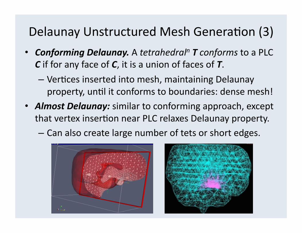
• Conforming Delaunay. A tetrahedraln T conforms to a PLC C if for any face of C, it is a union of faces of T.
– VerFces inserted into mesh, maintaining Delaunay property, unFl it conforms to boundaries: dense mesh!
• Almost Delaunay: similar to conforming approach, except that vertex inserFon near PLC relaxes Delaunay property. – Can also create large number of tets or short edges.

Delaunay Unstructured Mesh GeneraFon (3)
• Constrained Delaunay Tetrahedralns, CDTs, not fully Delaunay but have DT qualiFes.
• Fewer vertex inserFons, resoluFon control, w/o short edges. – T respects the PLC C: no segment of C cut in two by T, – There is a circumsphere S of T s.t. there is no vertex v of C that falls inside S & is visible from any point inside of T.
Advancing Front Unstructured Mesh GeneraFon
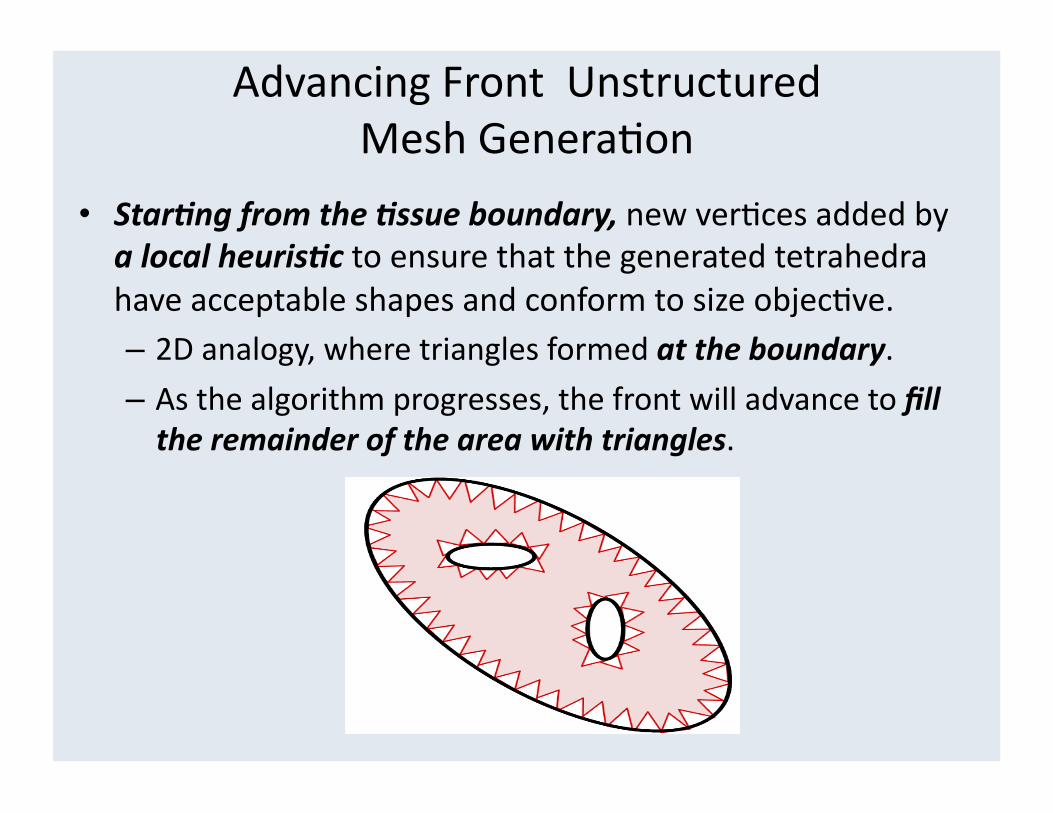
• Star)ng from the )ssue boundary, new verFces added by a local heuris)c to ensure that the generated tetrahedra have acceptable shapes and conform to size objecFve. – 2D analogy, where triangles formed at the boundary.
– As the algorithm progresses, the front will advance to fill the remainder of the area with triangles.

OpFmizaFon-‐based Unstructured Tetrahedral Mesh GeneraFon
• Varia)onal approaches view tet meshing as energy funcFonal, based on calculus of varia)ons.
• Mesh results from itera)ve minimiza)on of funcFonal, via vertex displacements and connec)vity changes.
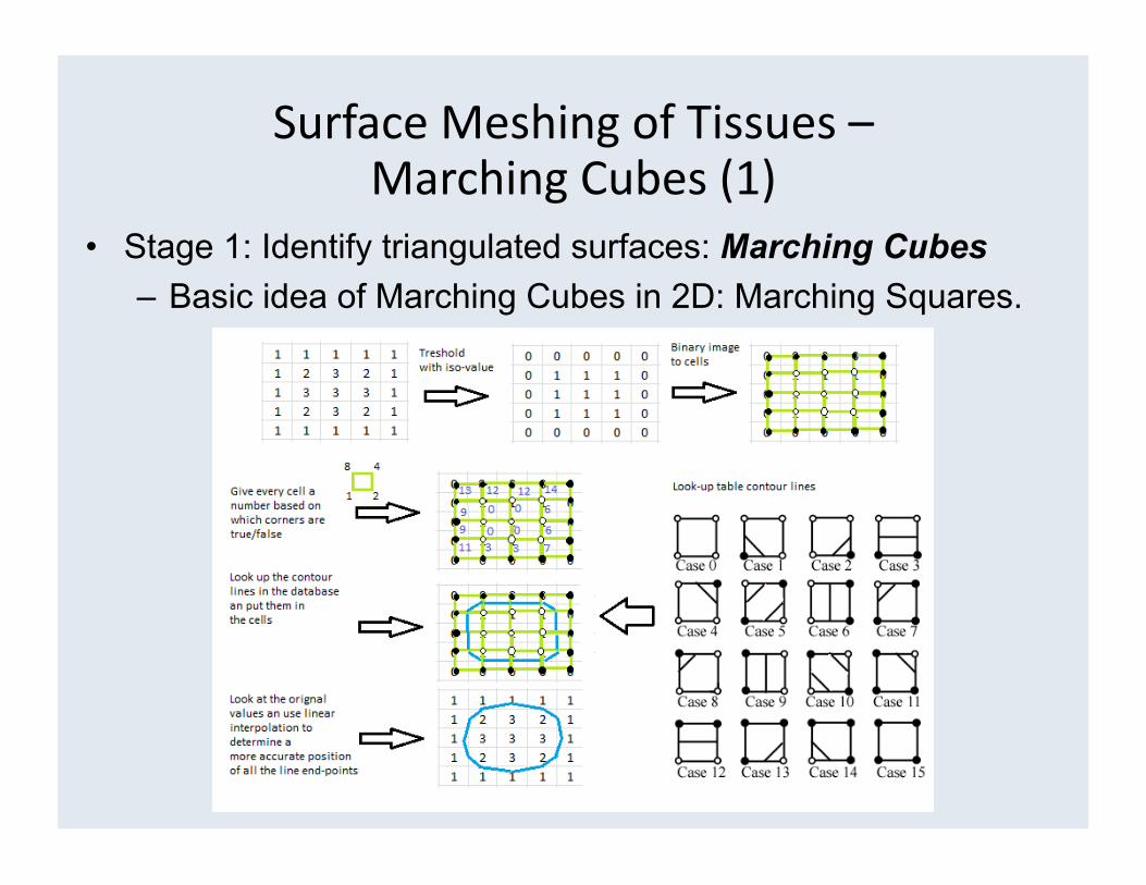
• Stage 1: Identify triangulated surfaces: Marching Cubes – Basic idea of Marching Cubes in 2D: Marching Squares.
Surface Meshing of Tissues – Marching Cubes (1)
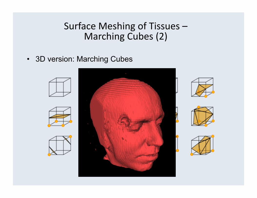
• 3D version: Marching Cubes
Surface Meshing of Tissues – Marching Cubes (2)

• Problem: Marching Cubes generates many triangles… • Stage 2: Decimation of Marching Cubes
569K ∆s 142K ∆s
Surface Meshing of Tissues – DecimaFon (1)

• Alternate approach: Simplex mesh topological operators • T1-T2 operators (Delingette): add/delete an edge
Surface Meshing of Tissues – DecimaFon (2)

• 6-edge face insertion or deletion (Gilles). • Provides both resolution control and produces highly
regular faces, e.g.: dual to high quality triangles.
Surface Meshing of Tissues – DecimaFon (2)
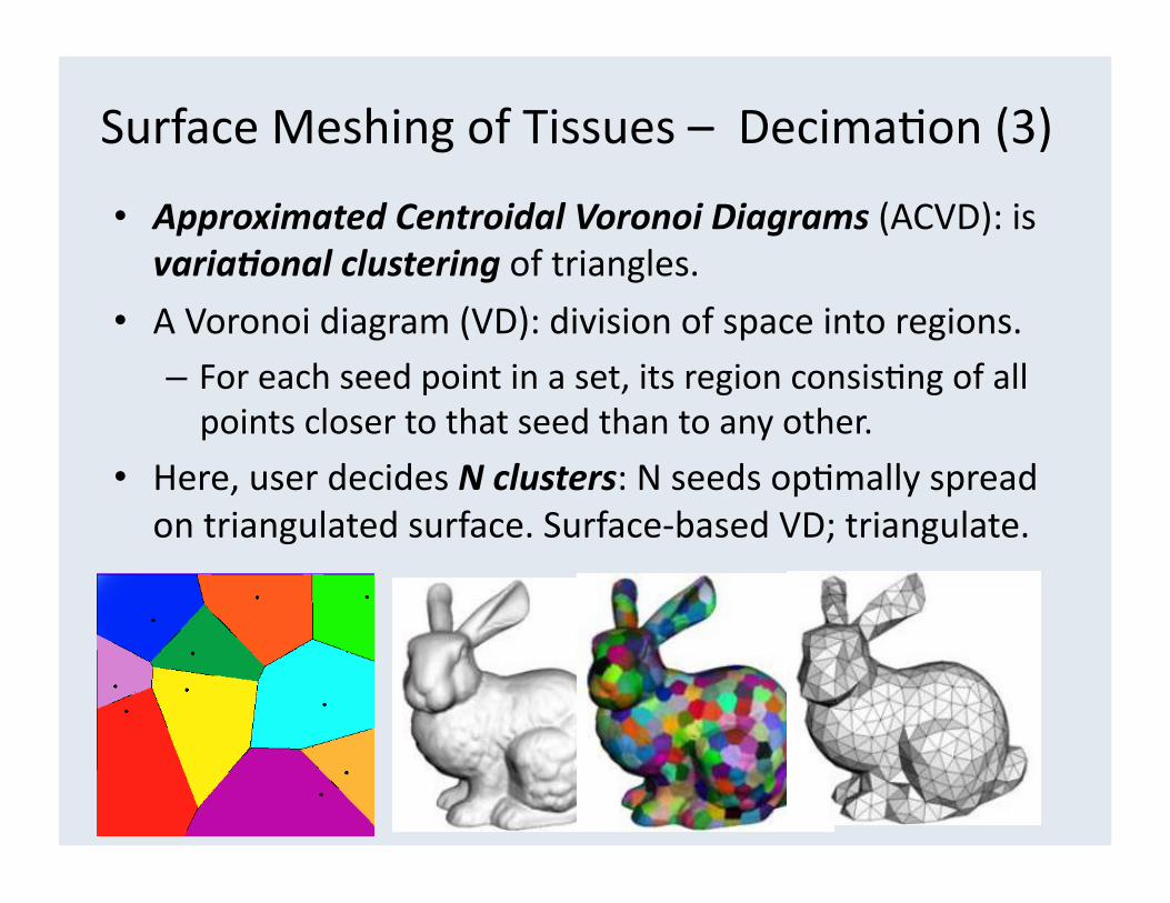
• Approximated Centroidal Voronoi Diagrams (ACVD): is varia)onal clustering of triangles.
• A Voronoi diagram (VD): division of space into regions. – For each seed point in a set, its region consisFng of all points closer to that seed than to any other.
• Here, user decides N clusters: N seeds opFmally spread on triangulated surface. Surface-‐based VD; triangulate.
Surface Meshing of Tissues – DecimaFon (3)