image registration in medical imaging medical image analysis
TRANSCRIPT

1
C.Studholme U.C.S.F. 1
Image Registration in Medical Imaging
Colin StudholmeAssociate Professor in Residence
Biomedical Image Computing Grouphttp://radiology.ucsf.edu/bicg
Department of Radiology and Biomedical ImagingUniversity of California San FranciscoUCSF/UCB Joint Graduate Group in
Biomedical Engineering
C.Studholme U.C.S.F. 2
Medical Image Analysis
• Large collection of research fields:– developing mathematical algorithms to extract and relate
information from medical images– For clinical and basic science research
• No “Physics of Medical Image Analysis”– Groups of suitable algorithms and mathematical approaches to
specific engineering problems
• Historically two key (and related) aspects of research:– Image Registration:
• finding spatial/temporal correspondences between image data and/or models
– Image Segmentation• Extracting/detecting specific features of interest from image data
• Many clinical motivations: – one of the key areas has been brain imaging, but many more!
C.Studholme U.C.S.F. 3
Medical Image Registration: Overview
• What is Registration?– Definitions– Classifications: Geometry, Transformations, Measures
• Motivation for work: Medical Image mis-registration– Where is image registration used in medicine and biomedical
research?
• Measures of Image Alignment:– Landmark/Feature Based Methods
– Voxel Based Methods: • Image Intensity Difference and Correlation• Multi-Modality Measures
C.Studholme U.C.S.F. 4
Registration
“the determination of a one-to-one mapping between the coordinates in one space and those in another,
such that points in the two spaces that correspond to the same anatomical point are mapped to each other.”
Calvin Maurer ‘93
2
C.Studholme U.C.S.F. 5
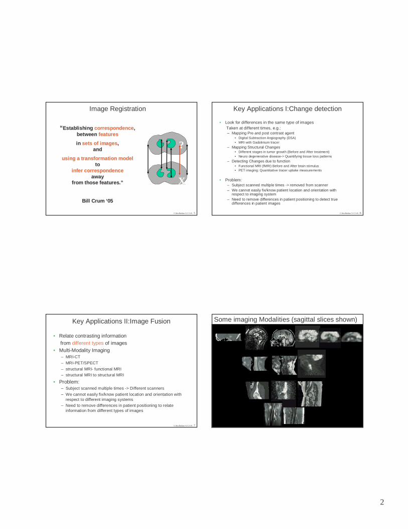
Image Registration
““ Establishing Establishing correspondencecorrespondence ,,between between featuresfeatures
in in sets of imagessets of images ,,and and
using a transformation modelusing a transformation modeltoto
infer correspondenceinfer correspondenceawayaway
from those features.from those features. ””
Bill Crum Bill Crum ‘‘0505
??
XX
C.Studholme U.C.S.F. 6
Key Applications I:Change detection
• Look for differences in the same type of images Taken at different times, e.g.:– Mapping Pre and post contrast agent
• Digital Subtraction Angiography (DSA)• MRI with Gadolinium tracer
– Mapping Structural Changes• Different stages in tumor growth (Before and After treatment)• Neuro degenerative disease-> Quantifying tissue loss patterns
– Detecting Changes due to function• Functional MRI (fMRI) Before and After brain stimulus• PET imaging: Quantitative tracer uptake measurements
• Problem:– Subject scanned multiple times -> removed from scanner– We cannot easily fix/know patient location and orientation with
respect to imaging system– Need to remove differences in patient positioning to detect true
differences in patient images
C.Studholme U.C.S.F. 7
Key Applications II:Image Fusion
• Relate contrasting information from different types of images
• Multi-Modality Imaging– MRI-CT
– MRI-PET/SPECT
– structural MRI- functional MRI– structural MRI to structural MRI
• Problem:– Subject scanned multiple times -> Different scanners
– We cannot easily fix/know patient location and orientation with respect to different imaging systems
– Need to remove differences in patient positioning to relate information from different types of images
C.Studholme U.C.S.F. 8
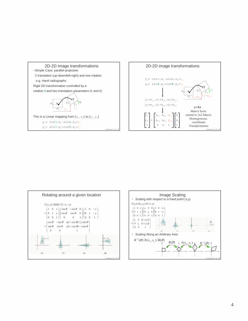
Some imaging Modalities (sagittal slices shown)

3
C.Studholme U.C.S.F. 9
Components of Image Registration Algorithms
–Image Data Geometries
•2D-2D, 2D-3D, 3D-3D
•Transformation Type
•Rigid/Affine/Non-Rigid
•Correspondence Criteria/Measure•Feature Based Methods
•Voxel Based/Dense Field Methods
•Optimization Method :
maximizing/minimizing criteria wrt T()
y=T(x)
PET(x)
MRI(y)
C.Studholme U.C.S.F. 10
Examples of Image Geometries and Transformation Models in Medical Applications
C.Studholme U.C.S.F. 11
Registration and display of the combined bone scan and radiographin the diagnosis and management of wrist injuries Hawkes et al, EJNM 1991
Technetium 99m and X-ray radiograph
2D-2D Inter Modality Image Registration Problem
C.Studholme U.C.S.F. 12
X-Ray
Nuc. Medicine
4
C.Studholme U.C.S.F. 13
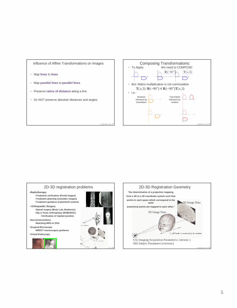
2D-2D image transformations–Simple Case: parallel projection
2 translation (up-down/left-right) and one rotation
e.g. Hand radiographs
Rigid 2D transformation controlled by a
rotation �
and two translation parameters t1 and t2:
This is a Linear mapping from (x1, x2) to (y1, y2)
y1= cos�.x1-sin�.x2+t1y2= sin�.x1+cos�.x2+t2
y
x
x1
x2 y1y2
t1t2
�C.Studholme U.C.S.F. 14
2D-2D image transformations
y1= cos�.x1-sin�.x2+t1y2= sin�.x1+cos�.x2+t2y1=a11.x1+a12.x2+a13
y2=a21.x1+a22.x2+a23
y1 a11 a12 a13 x1
y2 = a21 a22 a23 x2
1 0 0 1 1
Matrix form:extend to 3x3 Matrix
Homogeneous coordinate
Transformation
y
x
y=Ax
x1
x2 y1y2
t1=a13t2=a23
�
C.Studholme U.C.S.F. 15
Rotating around a given location
−−+−−
=
−−
⋅
−⋅
=
−−⋅⋅
100
sin)cos1(cossin
sin)cos1(sincos
100
10
01
100
0cossin
0sincos
100
10
01
),()(),(
θθθθθθθθ
θθθθ
θ
xy
yx
y
x
y
x
yxTRyxT
C.Studholme U.C.S.F. 16
Image Scaling• Scaling with respect to a fixed point (x,y)
• Scaling Along an Arbitrary Axis:
⋅−⋅−
=
−−
⋅
⋅
=
−−⋅⋅
100
)1(0
)1(0
100
10
01
100
00
00
100
10
01
),(),(),(
yss
xss
y
x
s
s
y
x
yxTssSyxT
yy
xx
y
x
yx
)(1 θ−R),( yx ssS)(θR)(),()(1 θθ RssSR yx ⋅⋅−
5
C.Studholme U.C.S.F. 17
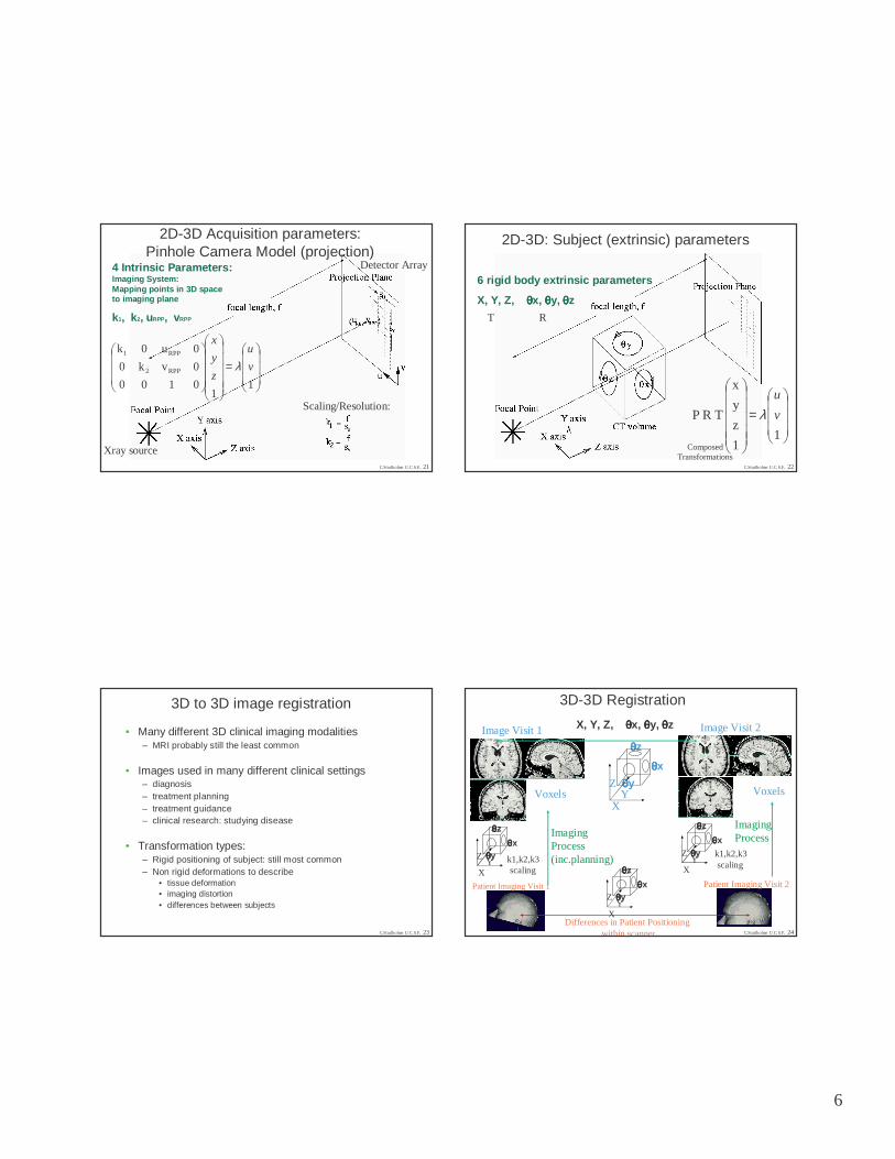
Influence of Affine Transformations on Images
• Map lines to lines
• Map parallel lines to parallel lines
• Preserve ratios of distance along a line
• Do NOT preserve absolute distances and angles
C.Studholme U.C.S.F. 18
Composing Transformations:• To Apply: We need to COMPOSE:
• But: Matrix multiplication is not commutative
• i.e.:
)90( °−R )3,( xT
)3,()90()90()3,( xx TRRT °−≠°−⋅
Translationfollowed by
rotation
Rotationfollowed bytranslation
C.Studholme U.C.S.F. 19
2D-3D registration problems•Radiotherapy:
•Treatment verification (Portal images)•Treatment planning (simulator images)•Treatment guidance (Cyberknife system)
• Orthopaedic Surgery•Spinal surgery (Brain Lab, Medtronic)•Hip or Knee Arthroplasty (ROBODOC)
•Verification of implant position
•Neurointerventions•Matching MRA to DSA
•Surgical Microscope •MRI/CT neurosurgery guidance
•Virtual Endoscopy:
C.Studholme U.C.S.F. 20
2D-3D Registration Geometry
•(A) Imaging/Acquisition Parameters ( intrinsic )•(B) Subject Parameters (extrinsic)
3D Image Data
2D Image Data
“the determination of a projection mapping,
from a 3D to a 2D coordinate system such that
points in each space which correspond to the same
anatomical points are mapped to each other.”
6
C.Studholme U.C.S.F. 21
2D-3D Acquisition parameters:Pinhole Camera Model (projection)
4 Intrinsic Parameters: Imaging System:Mapping points in 3D space to imaging plane
k1, k2, uRPP, vRPP
=
11
0
0
0
1
v
u
0
k
0
0
0
k
RPP
RPP
2
1
v
u
z
y
x
λ
Xray source
Detector Array
Scaling/Resolution:
C.Studholme U.C.S.F. 22
2D-3D: Subject (extrinsic) parameters
6 rigid body extrinsic parameters
X, Y, Z, θθθθx, θθθθy, θθθθz
=
11
z
y
x
T R P v
u
λ
T R
ComposedTransformations
C.Studholme U.C.S.F. 23
3D to 3D image registration
• Many different 3D clinical imaging modalities– MRI probably still the least common
• Images used in many different clinical settings– diagnosis– treatment planning– treatment guidance– clinical research: studying disease
• Transformation types:– Rigid positioning of subject: still most common– Non rigid deformations to describe
• tissue deformation• imaging distortion• differences between subjects
C.Studholme U.C.S.F. 24
3D-3D Registration
X, Y, Z, θθθθx, θθθθy, θθθθz
θθθθz
θθθθx
θθθθy
X
ZY
θθθθz
θθθθxθθθθy
X
ZY
Patient Imaging Visit 1 Patient Imaging Visit 2
θθθθz
θθθθxθθθθy
X
ZY
θθθθz
θθθθxθθθθy
X
ZY
Voxels Voxels
k1,k2,k3scaling
k1,k2,k3scaling
Differences in Patient Positioning within scanner
Image Visit 1 Image Visit 2
Imaging Process(inc.planning)
Imaging Process

7
C.Studholme U.C.S.F. 25
3D Rigid Transformations
−=
′′′
11000
0cossin0
0sincos0
0001
1
z
y
x
z
y
x
φφφφ
−
=
′′′
11000
0100
00cossin
00sincos
1
z
y
x
z
y
x
θθθθ
−
=
′′′
11000
0cos0sin
0010
0sin0cos
1
z
y
x
z
y
x
ωω
ωω
3 Translations x,y,z3 Rotations:
= ×××
110)( 131333 pTM
pT
C.Studholme U.C.S.F. 26
Feature Based Registration–Image Data Geometries
•2D-2D, 2D-3D, 3D-3D
•Transformation Type•Rigid/Affine/Non-Rigid
•Correspondence Criteria/Measure•Feature Based Methods
•Voxel Based/Dense Field Methods
•Optimization Method : Maximizing/minimizing Measure wrt T()
y=T(x)
PET(x)
MRI(y)
1. Extract Features From Images2. Evaluate Physical Distance Between Features3. Minimize Distance
C.Studholme U.C.S.F. 27
Feature Based Approaches
–Point set->Point set
(homologous)
–Point set->Point set
(non homologous..
so need to find order)
–Point set -> Surface
–Surface -> Surface
(also [space] Curve -> Surface)
1
3
2
1
3
2
1
3
2
?
3
?
C.Studholme U.C.S.F. 28
CTMR

8
C.Studholme U.C.S.F. 29
MR-CT REGISTRATION
• Manual point landmark identification (around 12 points) in MR and CT
• Accuracy of 1mm at center, and around 2 mm at the edge
• Relates soft tissue structures such as enhancing tumor and blood flow to bone features in CT
1
3
2
1
3
2
C.Studholme U.C.S.F. 30
Homologous Feature Based Alignment 1
3
2
1
3
2
•General case of two lists of correspondingfeature locations
[p1, p2… pN] and[q1, q2… qN]
both with N points•We want to Find:
Transformation T(q) that Minimizes squared distance between corresponding points:
E= Σr ||pr-T(qr )||2
•Where one set of points, q, is transformed by T()
-> Extrapolate Transformation for all image voxels/pixels
A
B
qqrr
pprr
C.Studholme U.C.S.F. 31
Procrustes Point Alignment[Golub&VanLoan, Matrix Computations, 1989]
• Remove Translational differences: Calculate translation that brings each of the point sets to the origin and subtract from each of
the point sets to create centered point sets:
q’ i=qi- 1/N�i qi
p’ i=pi- 1/N�i pi
Re-write centered point lists as matrices
p1 x1, y1 z1 q1 x’1, y’1 z’1p2 x2, y2 z2 q2 x’2, y’2 z’2p3 = x3, y3 z3 q3 = x’3, y’3 z’3
pN xN, yN zN qN x’N, y’N z’N
• Estimate Rotations: we want to find the rotation matrix R such that
– PT=R.QT
The system PT=R.QT is over-determined and there is noise, thus we want to find the rotation matrix R such that
minR = ||PT-R.QT||2
K. S. Arun, T. S. Huang, and S. D. Blostein. Least square fitting of two 3-d point sets. IEEE Transactions on Pattern Analysis and Machine Intelligence, 9(5):698 - 700, 1987.
P Q
P= Q=
C.Studholme U.C.S.F. 32
Procrustes Point Alignment
• Scale (procrustes normally includes estimate of scaling)– But can assume scanner voxel dimensions are accurate
• Rewrite expression PT=R.QT
QTPT=R.(QT Q)
• Now can decompose symmetric matrix QT Q using singular value decomposition (SVD):
(QT Q) -> (USVT)
• Here S is a diagonal matrix and VUT is the rotation matrix. For 2D:
VUT = cos(�
) -sin(�
)
sin(�
) cos(�
)
K. S. Arun, T. S. Huang, and S. D. Blostein. Least square fitting of two 3-d point sets. IEEE Transactions on Pattern Analysis and Machine Intelligence, 9(5):698 - 700, 1987.
[ ]
P�
Q

9
C.Studholme U.C.S.F. 33
Alternatives to SVD alignment
Alternative transformation decompositions and parameterizations can be used eg:
• Quaternion methods:– B. K. P. Horn. Closed-form solution of absolute orientation using unit quaternions.
Journal of the Optical Society of America A, 4(4):629 - 642, April 1987.
• Orthonormal matrices:– B. K. P. Horn, H. M. Hilden, and Sh. Negahdaripour.
Closed-form solution of absolute orientation using orthonormal matrices. Journal of the Optical Society of America A, 5(7):1127 - 1135, July 1988.
• Dual quaternions: – M. W. Walker, L. Shao, and R. A. Volz.Estimating 3-d location parameters
using dual number quaternions. CVGIP: Image Understanding, 54:358 -367, November 1991.
• These algorithms generally show similar performance and stability with real world noisy data:
– A. Lorusso, D. Eggert, and R. Fisher. A Comparison of Four Algorithms for Estimating 3-D Rigid Transformations. In Proceedings of the 4th British Machine Vision Conference (BMVC '95), pages 237 - 246, Birmingham, England, September 1995.
C.Studholme U.C.S.F. 34
Manual Landmark Based Registration
D.L.G. Hill, et al, Accurate Frameless Registration of MR and CTImages of the Head: Applications in Surgery and Radiotherapy Planning, Radiology, 191, 1994, pp 447-454.
C.Studholme U.C.S.F. 35 C.Studholme U.C.S.F. 36
0
0.5
1
1.5
2
2.5
-100 -90 -80 -70 -60 -50 -40 -30 -20 -10 0 10 20 30 40 50 60 70 80 90 100
mm
RM
S error (mm)
4 points
8 points16 points
Extrapolating Transformations:THEORETICAL POINT BASED REGISTRATION ERROR
(points on circle 50mm radius selected with RMS err or of 2mm)
1
3
2
1
3
2
Important factor: registration error lowest where 3D landmarks can be found
The distribution of target registration error in rigid-body point-based registrationFitzpatrick, J.M.; West, J.B. Medical Imaging, IEEE Transactions onVolume 20, Issue 9, Sep 2001 Page(s):917 - 927

10
C.Studholme U.C.S.F. 37
Approaches to Landmark/Feature Extraction and Matching
• Markers Attached to Subject (rigid bone attachment?)– Need to be visible in different types of Images[Hawkes et al Registration and display of the combined bone scan and radiograph in the
diagnosis and management of wrist injuries, EJNM 1991]
• Manual Landmark identification– Time consuming, introduce errors, difficult to find true consistent 3D
landmarks: But VERY flexible and can adapt to data.[D.L.G. Hill, et al, Accurate Frameless Registration of MR and CT Images of the Head: Applications in Surgery and Radiotherapy Planning, Radiology, 191, 1994, pp 447-454.]
• Automated Landmark Identification: geometric models of local anatomy: – Need to be true unique 3D points in intensity map: tip-like, saddle-like, and sphere-like
structures.– Need to be consistent in different subjects and image types[Stefan Wörz, Karl Rohr Localization of anatomical point landmarks in 3D medical images
by fitting 3D parametric intensity models, Medical Image Analysis Volume 10, Issue 1, Page 41-58, Feb 2006.]
• Non-Homologous Landmarks/ 3D Structures:– Easier to automatically find general features: for example points on a surface using
edge detection.– But: Which point maps to which point? – Need to then find correspondence and alignment: Point Cloud Fitting
C.Studholme U.C.S.F. 38
Early Feature Based Brain/Head Matching
•“Head-hat” matching of Head surfaces. Retrospective Geometric Correlation of MR, CT and PET Images,
Levin, Pelizzari, Chen, Chen Cooper, Radiology, 1988
•Chamfer Distance Matching: Borgefors 1986 Jiang 1992
C.Studholme U.C.S.F. 39
Alignment of non-Homologous Feature Locations: fuzzy correspondence
General case of two lists of point locationsP==[p1, p2… pN] and Q==[q1, q2… qM]with N and M points respectively,and a list of weights [kij ]to describe the fuzzy correspondence between every possible point pair:
Registration error can then be expressed as.
E(R,t)= Σi Σj kij||pi-(Rqj+t)||2
But… need to estimate both R, t and correspondence [[kkijij ].].
PQ
k21
k23
C.Studholme U.C.S.F. 40
Iterative Closest Point AlgorithmApproximates correspondence matrix [[kkijij ]] by assigning each point to
the current closest point.
• Applying current transformation R and t to Q==[q1, q2… qM]
So that
Q’ = RQi+t
• Take each point Pi=[p1, p2… pN] and search list Q’ i to find the
nearest point Qii to create a new list with N points.
• Apply Least Squares fit of current nearest points (eg using Procrustes point matching) to estimate R and t
• Repeat Until Change in transformation falls below threshold.
P. Besl and N. McKay. A method for Registration of 3-D Shapes. IEEE Transactions on Pattern Analysis and Machine Intelligence (PAMI), 14(2):
239 256, February 1992.

11
C.Studholme U.C.S.F. 41
I.C.P. advantages and disadvantages
• Can be applied to both discrete landmarks, lines, surfaces etc
• But: Highly dependent on starting estimate!– Only finds a local optima
– Can use multi-start to improve search
• Search for closest point in large point lists or surfaces can be computationally expensive
C.Studholme U.C.S.F. 42
Improvements/Adaptations in ICP•Orientation driven ICP:Matches location and local boundary/surface orientation
[Godin 2001,Schutz 1998]
•Subsampling: Choosing only meaningful points•Eg points on curved parts of surface
•Optimized Searching Techniques to find closest point
Multi-resolution Matching•Outlier rejection: to handle outliers and also
incomplete overlap
[S. Rusinkiewicz, M. Levoy, Efficient Variants of the ICP Algorithm, Proc 3rd
international conference on 3D digital Imaging 2001]
C.Studholme U.C.S.F. 43
Fuzzy Correspondence and Point Matching
Now a very large field in both computer vision and medical image analysis, with many different approaches proposed
H. Chui and A. Rangarajan, A New point Matching Algorithm for non-rigid registration, Computer Vision and Image Understanding, vol 89, Issue 2-3, 2003.
Z. Xue, D. Shen, E Khwang Teoh, An Efficient fuzzy algorithm for aligning shapes under affine transformations, Pattern Recognition, Volume 34, Issue 6, June 2001.
C.Studholme U.C.S.F. 44
Validation of Rigid Body Registration
• Between Modality validation a difficult problem:– Need to introduce corresponding features visible in different
imaging systems – That can be found accurately in each modality – That have fixed relationship with underlying anatomyCalvin R. Maurer, J. Michael Fitzpatrick, Matthew Y. Wang, Student Member, Robert L.
Galloway, Robert J. Maciunas, George S. Allen, Registration of Head Volume Images Using Implantable Fiducial Markers (1997) IEEE Transactions on Medical Imaging
• This successfully used to evaluate MRI-CT, MRI-MRI and MRI-PET registration using bone implanted markersJ. West, J.M. Fitzpatrick, M.Y. Wang, B.M. Dawant, C.R. Maurer, R.M. Kessler, R.J.
Maciunas, C. Barillot, D. Lemoine, A. Collignon, F. Maes, P. Suetens, D. Vandermeulen, P.A. van den Elsen,S. Napel,T.S. Sumanaweera, B. Harkness, P.F. Hemler, D.L.G. Hill, D.J. Hawkes, C. Studholme, J.B.A Maintz, M.A. Viergever, G. Malandain, X. Pennec, M.E. Noz,G.Q. Maguire, M. Pollack, C.A. Pelizzari, R.A. Robb,D. Hanson, R.P. Woods, Comparison and Evaluation of Retrospective Intermodality Brain Image Registration Techniques , J. Comp. Assist. Tomog. Vol21(4), 1997, pp 554-566.

12
C.Studholme U.C.S.F. 45
Challenges in Automating medical image registration
–Finding suitable features
–e.g. true 3D landmarks
–Finding the same feature in different types of images
–Not computer vision!
–no nice edges/corners and man made scenes
–Variable/limited anatomical coverage
–No scanner images the whole body
–truncated: part of head or at neck
–Makes using global methods
–Variable/low contrast to noise
C.Studholme U.C.S.F. 46
Feature Based Registration–Image Data Geometries
•2D-2D, 2D-3D, 3D-3D
•Transformation Type•Rigid/Affine/Non-Rigid
•Correspondence Criteria/Measure•Feature Based Methods
•Voxel Based/Dense Field Methods
•Optimization Method : •Maximizing/minimizing Measure wrt T()
y=T(x)
PET(x)
MRI(y)
1. Define Suitable Image Similarity Measure2. Optimise Similarity wrt Transform T()
C.Studholme U.C.S.F. 47
Pixel/Voxel Based Registration
• History: Template Matching– Detecting an object or feature based on pixel/voxel values
• Avoid the need to automatically extract corresponding landmarks or surfaces
• Similarity Measures for Image Registration can Assume:– linear intensity mapping– non-parametric 1-to-1 intensity mapping– non-parametric many-to-1 intensity mapping
• Simplest: Image Intensity Difference
C.Studholme U.C.S.F. 48
Iterative Refinement of Transformation Parameters: small displacements
Consider 1D case:for no noise, assumew(x) is some exact translation of f(x)
f(x)
w(x)
w(x)= f(x+t)and image ‘mis match’ or error for given displacement t can simply beLocal Difference in intensity:e(t)=f(x+t)-w(x)
t
Locationx
Imageintensity
w(x) f(x)
[Lucas and Kanade, An Iterative Image Registration Technique with an Application to Stereo VisionProc Image Understanding Workshop, P121-130, 1981]
13
C.Studholme U.C.S.F. 49
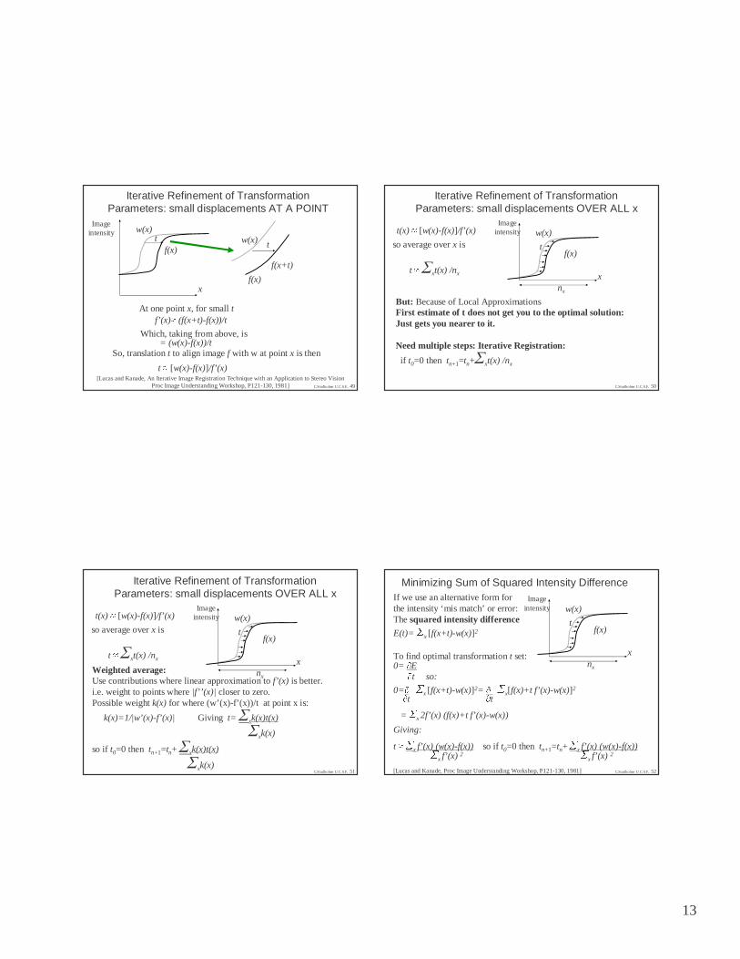
Iterative Refinement of Transformation Parameters: small displacements AT A POINT
f(x)
w(x)t
x
Imageintensity
At one point x, for small tf’(x)� (f(x+t)-f(x))/t
= (w(x)-f(x))/tWhich, taking from above, is
So, translation t to align image f with w at point x is then
t � [w(x)-f(x)]/f’(x)
f(x)
w(x) t
[Lucas and Kanade, An Iterative Image Registration Technique with an Application to Stereo VisionProc Image Understanding Workshop, P121-130, 1981]
f(x+t)
C.Studholme U.C.S.F. 50
Iterative Refinement of Transformation Parameters: small displacements OVER ALL x
t(x) � [w(x)-f(x)]/f’(x)
t � xt(x) /nx
so average over x is
But: Because of Local ApproximationsFirst estimate of t does not get you to the optimal solution:Just gets you nearer to it.
Need multiple steps: Iterative Registration:
if t0=0 then tn+1=tn+ xt(x) /nx
f(x)
w(x)
t
x
Imageintensity
nx
C.Studholme U.C.S.F. 51
Iterative Refinement of Transformation Parameters: small displacements OVER ALL x
t(x) � [w(x)-f(x)]/f’(x)
t � xt(x) /nx
so average over x is
Weighted average:Use contributions where linear approximation to f’(x) is better.i.e. weight to points where |f’’(x)| closer to zero.Possible weight k(x) for where (w’(x)-f’(x))/t at point x is:
k(x)=1/|w’(x)-f’(x)| Giving t= xk(x)t(x)
xk(x)
so if t0=0 then tn+1=tn+ xk(x)t(x)
xk(x)
f(x)
w(x)
t
x
Imageintensity
nx
C.Studholme U.C.S.F. 52
Minimizing Sum of Squared Intensity DifferenceIf we use an alternative form forthe intensity ‘mis match’ or error:The squared intensity difference
E(t)= �
x [f(x+t)-w(x)]2
To find optimal transformationt set:0= �E�t so:
0=� �x [f(x+t)-w(x)]2= � �
x[f(x)+t f’(x)-w(x)]2�t �t= �
x 2f’(x) (f(x)+t f’(x)-w(x))
Giving:
t �� x f’(x) (w(x)-f(x)) so if t0=0 then tn+1=tn+ �
x f’(x) (w(x)-f(x))�x f’(x) 2
�x f’(x) 2
[Lucas and Kanade, Proc Image Understanding Workshop, P121-130, 1981]
f(x)
w(x)
t
x
Imageintensity
nx

14
C.Studholme U.C.S.F. 53
Extension to N dimensional ImagesThe squared intensity difference can be extended to the case wherelocation x and translation t are vectors of N dimensions:
E(t)= �
x€R[f(x+ t)-w(x)]2
As for 1D, we can then use a linear approximation for small t so that
f(x+ t)=f(x)+ t � f(x)�xWe can then set0= �E�t so:
0=� �x∈∈R [f(x)+t � f(x) -w(x)]2 =�
x∈∈R 2 �f(x) [f(x)+t � f(x)-w(x)]�t �x �x �xand then
t=[�
x∈∈R [�f(x)/�x]T[w(x)-f(x)] ][�
x∈∈R (�f(x)/�x)T (�f(x)/�x) ]-1
[Lucas and Kanade, Proc Image Understanding Workshop, P121-130, 1981] C.Studholme U.C.S.F. 54
Other forms of Linear Spatial Transformations
w(x)=f(xA+ t)
Mapping from One space to the other can be described by a Linear 3x3 transformation matrix A and a translation vector tSo, we assume at the correct transformation:
E(A,t)= �
x∈∈R [f(xA+t)-w(x)]2
and intensity error is
f(x(A+�
A)+(t+�
t))� f(xA+ t) + (x�
A+�
t) � f(x)�xTo minimize this, one approach is to use a linear approximation to changes in transformation
[Lucas and Kanade, Proc Image Understanding Workshop, P121-130, 1981]
C.Studholme U.C.S.F. 55
Alternative Image Similarity Measuresfor Image Alignment
C.Studholme U.C.S.F. 56
Global Intensity Variations
• Many Medical Images have ‘uncalibrated’ intensities – Gain or illumination changes
• Common Issue: linear intensity scaling and offset f’=w.k+b
template intensity
targ
et im
age
inte
nsity
template intensity
targ
et im
age
inte
nsity
Target Image Template Image
• Absolute difference will not tend to zero at correct match:– OR Worse: minimum does not correspond to correct match
15
C.Studholme U.C.S.F. 57
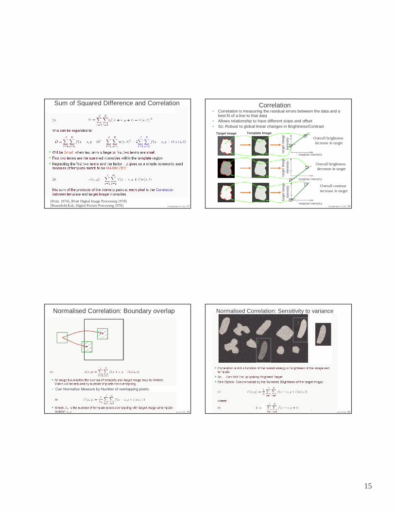
Sum of Squared Difference and Correlation
[Pratt, 1974], [Pratt Digital Image Processing 1978][Rosenfeld,Kak, Digital Picture Processing 1976] C.Studholme U.C.S.F. 58
Correlation
template intensity
targ
et im
age
inte
nsity
template intensity
targ
et im
age
inte
nsity
Target image Template Image
template intensity
targ
et im
age
inte
nsity
• Correlation is measuring the residual errors between the data and a best fit of a line to that data
• Allows relationship to have different slope and offset• So: Robust to global linear changes in Brightness/Contrast
Overall brightnessincrease in target
Overall brightnessdecrease in target
Overall contrastincrease in target
C.Studholme U.C.S.F. 59
Normalised Correlation: Boundary overlap
• Can Normalize Measure by Number of overlapping pixels:
C.Studholme U.C.S.F. 60
?
?
Normalised Correlation: Sensitivity to variance

16
C.Studholme U.C.S.F. 61
Variance?
template intensity
Tar
get i
mag
ein
tens
ity
template intensity
Tar
get i
mag
ein
tens
ity
• Problem: Match may still be biased by variance in Target/Template
C.Studholme U.C.S.F. 62
Correlation Coefficient
• Normalise Correlation by the summed residuals around mean in template and target overlap:
template intensity
Tar
get i
mag
ein
tens
ity
C.Studholme U.C.S.F. 63
What about non-linear intensity mappings?
template intensity
Tar
get i
mag
ein
tens
ity
template intensity
Tar
get i
mag
ein
tens
ity
C.Studholme U.C.S.F. 64
Non-Linear Intensity Mapping
template intensity
Tar
get i
mag
ein
tens
ity

17
C.Studholme U.C.S.F. 65
Multi Modality Similarity Measures
Matching Images with Different Tissue Contrast Properties
C.Studholme U.C.S.F. 66
• But Intensity mapping is not usually smooth or easily parameterized(e.g. discrete because of different tissue classes)
• Assume only 1-to-1 mapping of intensities between template and target:
template intensity w
Tar
get i
mag
ein
tens
ity f
template intensity w
Tar
get i
mag
ein
tens
ity f Register
Non-parametric 1-to-1 mapping
Target f
Template w
Target f
Template w
Register
C.Studholme U.C.S.F. 67
SPECT-MRI registration:Patient orientated differently with respect to scanner coordinates:
1.Head rest design2.Gantry angle limitations3. No easy to find 3D landmarks
C.Studholme U.C.S.F. 68
SPECT-MRI registration

18
C.Studholme U.C.S.F. 69
The Effects of Misregistrationin Intensity Feature Space
Registered Translated by 2mm Translated by 5mm Translated by 8mm
C.Studholme U.C.S.F. 70
• Used for MRI-PET/SPECT registration– MRI scan scalp edited-> Only consider intra-cranial tissues– Grey-white-CSF values in cranial region differ
• Non-monotonic mapping• Approx 1-to-1
Partitioned Image Uniformity[Woods et al JCAT 93]
MRI intensity w
PE
T/S
PE
CT
int
ensi
ty f
AIR/CSF
Grey Matter
White Matter
T1 Weighted MRI
HMPAO SPECT image
C.Studholme U.C.S.F. 71
Partitioned Image Uniformity[Woods et al JCAT 93]
template intensity w
Tar
get i
mag
ein
tens
ity f
b=1 b=2 b=3 b=4
C.Studholme U.C.S.F. 72
Functional/Structural Fusion:
MRI-SPECT

19
C.Studholme U.C.S.F. 73
Correlation Ratio[A. Roche et al MICCAI 98]
template intensity w
Tar
get i
mag
ein
tens
ity f
b=1 b=2 b=3 b=4
•Need to avoid picking region with small variance:
Correlation Ratio:C.Studholme U.C.S.F. 74
MR-CT Registration in the Skull Base
• CT (and MR) image volume often targeted with limited axial extent.
• Automated segmentation or identification of features is difficult.
• Axial resolution limited.
Need to make best use of all shared features in the images.
C.Studholme U.C.S.F. 75
MR and CT
Manual Registration Estimate (Using Corresponding Anatomical Landmarks)
C.Studholme U.C.S.F. 76
Correlation Coefficient
c
h(m,c)
m
Assumes Linear Relationship between MR and CT intensity.
Improved by using only modified soft tissue or bone intensities from CT. (Van den Elsen, 1994).

20
C.Studholme U.C.S.F. 77
Many-to-1 Intensity Mapping ?
Where one image type can detect sub classes of tissue, while the other sees one.(e.g. T1 weighted MRI vs CT)
template intensity w
Tar
get i
mag
ein
tens
ity f
Target f
Template w
One/few soft tissue intensities
Multiple soft tissue intensities
C.Studholme U.C.S.F. 78
Changes in 2D Histogram with Alignment
MR
CT
C.Studholme U.C.S.F. 79
How to Characterize Alignment?-> ‘Histogram Sharpness’
template intensity w
Tar
get i
mag
ein
tens
ity f
template intensity w
Tar
get i
mag
ein
tens
ity f
ww
f f
?
C.Studholme U.C.S.F. 80
Information and Entropy[Collignon, CVRMED 95]
p(w,f)p(w,f)
If guessing what pair of values (w,f) a pixel will have...
Small number of high-probability pairs
Larger number of lower-probability pairs
Less Uncertainty More Uncertainty
Overall: Image Pair Provides Less Information...
‘Less Complex’
Overall: Image Pair Provides More Information..
‘More Complex’
mis-registeredregistered
w
f f

21
C.Studholme U.C.S.F. 81
Information and Entropy[Collignon, CVRMED 95]
p(w,f)p(w,f)
w w
ff
H(W,F) is Minimized
are
mis-registeredregistered
C.Studholme U.C.S.F. 82
Mutual Information[Viola and Wells: ICCV 95, Collignon et al: IPMI 95]
• Joint entropy, like correlation and correlation ratio, is influenced by the image structure in the image overlap– The changing transformation modifies the
information provided by the images
• Instead: form a measure of the relative information in the Target image with respect to Template using Mutual information:– difference between marginal and joint entropies
I(F,W)=H(F)+H(W)-H(F,W)to be Maximized
where
H(F)= ∫ f –p(f) log (p(f))
H(W)= ∫ w –p(w) log (p(w))
H(F,W)= ∫ f ∫ w –p(f,w) log (p(w,w))
C.Studholme U.C.S.F. 83
MRI-CT for skull base surgery planning
C.Studholme U.C.S.F. 84

22
C.Studholme U.C.S.F. 85 C.Studholme U.C.S.F. 86
– MI behavior varies
– MI Behavior Depends of Field of View:• can have clear maximum away from alignment
Information Measures and Overlap
p(w,f)w w
ff
largerpeaks
smallerpeaks
MI big!more infoin target
explained bytemplate
C.Studholme U.C.S.F. 87
Normalised Mutual Information[Studholme et al, 1998]
• When mutual information is used to evaluate the alignment of twofinite images: overlap still has an confound:– Both Marginal entropies, H(F) and H(W) vary
• Alignment can be driven by choosing overlap that has large H(F) and H(W).– e.g. overlap with equal area of background and foreground intensities
• Rather than look for difference in joint and marginal entropies,use their ratio (like correlation coefficient):
Y(F,W)=H(F)+H(W)H(F,W) to be Maximized
But.... Does not solve all problems!C.Studholme U.C.S.F. 88
MINMI

23
C.Studholme U.C.S.F. 89
MRI-CT Registration
C.Studholme U.C.S.F. 90
MRI-CT Registration
C.Studholme U.C.S.F. 91
3D Rigid MR-CT Registration in the Skull Base
C.Studholme U.C.S.F. 92
Image Fusion for Skull Base Surgery PlanningHawkes et al, 1993
CT: BoneMR Gadolinium: TumorMRA: Blood Vessels

24
C.Studholme U.C.S.F. 93
RegisteredMR+PET
C.Studholme U.C.S.F. 94
Subtraction SPECT Imagingin Epilepsy
Inter-Ictal Ictal Change in Uptake
C.Studholme U.C.S.F. 95
• High Contrast F.D.G. Uptake in Regions of Interest.
• Some Soft Tissue Detail.
• F- Tracer Added to Highlight Bone Structure.
C.Studholme U.C.S.F. 96
Shared Features in MR and PET Images of the Pelvis
• Bone Features • PET: F- Uptake.• MR: Marrow White.
• Soft Tissue• Some Boundaries in PET: Very Low Contrast.• Deformed by Different Bed Shapes.

25
C.Studholme U.C.S.F. 97 C.Studholme U.C.S.F. 98
Its still only overlaps of intensities…The biggest overlaps drive the registration
C.Studholme U.C.S.F. 99
Summary• A range of medical alignment measures have been
developed in the last 15yrs
• These vary in the assumptions they make about the relationship between intensities in the two images being matched
• Many other criteria not covered!
• Many ways of modifying the criteria:– Evaluation at multi resolution/scale– Edge/boundary/geometric feature extraction: modify contrast– Spatial windowing and encoding can localize the criteria
• Best criteria will depend on the type of data you have:– How different the information provided and what contrast is shared– How much they overlap
C.Studholme U.C.S.F. 100
Bibliography I• [Barnea and Silvermann 72], Barnea and Silvermann 72 IEEE Transactions on
Computing 21(2), 179-186,1972.• [Pratt 1974], Pratt, IEEE Tran. Aerospace and Elec. Systems, 10(3), pp 353-
358,1974]• [Woods et al JCAT 93] R.P. Woods, J.C. Mazziotta, S.R. Cherry, “MRI-PET
Registration with Automated Algorithm”, J. Computer Assisted Tomography, vol17(4), pp 536-546, 1993.
• [Roche et al, 98], A. Roche, G. Malandain, X. Pennec, N. Ayache, “The correlation ratio as a new similarity measure for Multimodal Image Registration”, In Proc. Medical Image Computing and Computer Assisted Intervention, 1998, pp 1115-1124, Springer LNCS.
• [Hill VBC94], D.L.G. Hill, C. Studholme, D.J. Hawkes, “Voxel similarity measures for automated image registration”, Proc. Visualization in Biomedical Computing, ed. R.A. Robb, SPIE press, 1994, Bellingham.
• [Collignon, CVRMED 95]. A. Collignon, D. Vandermeulen, P. Suetens, G. Marchal, “3D multimodality medical image registration using features spaceclustering”, proc. of Computer Vision, Virtual Reality and Robotics in Medicine, 1995, pp 195-204, Springer LNCS.
• [Collignon, IPMI95], A. Collignon, F. Maes, D. Delaere, D. Vandermeulen, P. Seutens, G. Marchal, “Automated multi-modality image registration based on information theory”, Proc. of Information Processing in Medical Imaging, 1995, pp. 263-274. Kluwer, Dordrecht.

26
C.Studholme U.C.S.F. 101
Bibliography II• [Viola, ICCV 1995], P. Viola, W. Wells, “Alignment by Maximization of mutual
information”, Proc. of International Conference on Computer Vision, 1995, pp16-23. Ed. Grimson, Schafer, Blake, Sugihara.
• [Studholme et al 1998] C. Studholme, D.L.G. Hill, D.J.Hawkes ,A NormalisedEntropy Measure of 3D Medical Image Alignment, Proceedings of SPIE Medical Imaging 1998,San Diego, SPIE Press. pp. 132-143.
• [Studholme et al, 1999], C. Studholme, D.L.G.Hill, D.J. Hawkes, An Overlap Invariant Entropy Measure of 3D Medical Image Alignment, Pattern Recognition, Vol. 32(1), Jan 1999, pp 71-86.
• [Maes et al, TMI97], F. Maes, A. Collignon, S. Vandermeulen, G. Marchal, P.Suetens, “ Multimodality image registration by maximization of mutual information”, IEEE Transactions on Medical Imaging, Vol 16, pp187-198, Apr 1997.Review Articles:
• [Pluim, TMI03] J. Pluim, J.B.A. Maintz, M. Viergever, “Mutual Information Based Registration of Medical Images: A Survey”, IEEE Transactions on medical imaging, vol 22(8), pp 986-1004, 2003.
• [Hill, PMB01] D.L.G. Hill, P.G. Batchelor, M. Holden, D.J. Hawkes, “Medical image registration”, Physics in Medicine and Biology, 2001, vol 46(3), pp 1-45.
• [Maintz, MIA98], J.B.A. Maintz, M.A. Viergever, “A survey of medical image registration”, Medical Image Analysis, vol 2(1), pp 1-36, 1998.
• [Elsen, EMB93], P.A. van den Elsen, E.J.D. Pol, M.A. Viergever, “Medical Image Matching- A Review with Classification”, IEEE Engineering in Medicine and Biology Mag., vol 12, pp 26-39, Mar 1993.