additive manufacturing processes for infrastructure
TRANSCRIPT

1 Copyright © 2019 by ASME
Proceedings of the ASME 2019 International Manufacturing Science and Engineering Conference MSEC2019
June 10–14, 2019, Erie, Pennsylvania, USA
ADDITIVE MANUFACTURING PROCESSES FOR INFRASTRUCTURE
CONSTRUCTION: A REVIEW
Abhinav Bhardwaj a, Scott Z Jones b, Negar Kalantar c, Zhijian Pei a,
John Vickers d, Timothy Wangler e, Pablo Zavattieri f, Na Zou a
a Department of Industrial & Systems Engineering, Texas A&M University, College Station, TX 77840 b National Institute of Standards and Technology, 100 Bureau Drive, Stop 8615, Gaithersburg, MD 20899, USA
c Department of Architecture, Texas A&M University, College Station, TX 77840 d Space Technology Mission Directorate, National Aeronautics and Space Administration (NASA)
e Institute for Building Materials, ETH Zurich, Switzerland f Lyles School of Civil Engineering, Purdue University, West Lafayette, IN 47907, USA
ABSTRACT
Additive manufacturing (AM) has had an enormous impact in the manufacturing sector. Its role has evolved from printing prototypes to manufacturing functional parts for a variety of applications in the automotive, aerospace, and medical industries. Recently, AM processes have also been applied in the infrastructure construction industry. Applications of AM processes could bring in significant improvements in infrastructure construction, specifically in the areas of productivity and safety. It is desirable to have a review on the current state of these emerging AM processes for infrastructure construction as well as existing gaps in this field. This paper reviews AM processes in infrastructure construction. It discusses the process principle, application examples, and gaps for each of the AM processes. 1. INTRODUCTION
AM has found increasing applications in aerospace [1], [2], industrial/business machines [2], motor vehicles [3], consumer products/electronics [4], [5], medical [6], [7], and architectural industries [8]. However, the architectural and the construction industry account for only 3.1% of the total AM applications [8].
The global annual output of the construction industry is $8.5 trillion [9]. In industrialized countries, the construction industry employs 6% to 10% of the workforce [10]. However, the construction industry also faces major challenges in safety and productivity. Estimated by the International Labor Organization, one fatal accident occurs every ten minutes on construction sites around the world [10]. Productivity in the construction industry is also perceived to be declining or stagnant [11], [12].
In the U.S., the construction industry is one of the leading contributors to the economy, and accounted for 4.3% of the total national employment in 2016 [13], [14]. However, in 2016, the American Society of Civil Engineers assigned a
grade of D+ to the U.S. infrastructure [15]. Restoration and improvement of urban infrastructure has been identified as a grand challenge for engineering in the 21st century by the National Academy of Engineering [16]. With respect to building better infrastructure, the Academy professed the importance of new construction methods. It stated, “Novel construction materials may help address some of these challenges. But dramatic progress may be possible only by developing entirely new construction methods” [17].
AM processes can make a significant contribution to the construction industry. First, human safety would improve due to development of automated construction systems that can carry-out dangerous jobs that were previously performed by humans. Additionally, AM machines could work 24 hours a day and 7 days a week thereby providing a momentous boost to productivity. In concrete construction, more than 50% of the total cost is spent on formwork and labor [18]. AM processes can present significant cost savings through printing of stay-in-place formworks [19].
Application of AM processes for construction has gathered interest in several countries. In the U.S., the National Science Foundation (NSF) supported a workshop on AM for Civil Infrastructure Design and Construction to review and examine future prospects of AM processes [20]. Several companies have emerged globally in the field of AM for construction applications.
Several review papers in the field exist. They focused on particular materials such as concrete [21], [22], discussed trends in the field [23], and presented technologies prevalent at the time of publication [24], [25]. Rapid and significant developments in this field merit an up-to-date review. The primary goal of this state-of-the-art paper is to document AM processes in infrastructure construction. In this paper, “Infrastructure” refers to large-scale civil and architectural structures such as houses and bridges.

2 Copyright © 2019 by ASME
Table 1 presents various AM processes presented in this paper. Following this introduction, Sections 2 to 5 discuss additive manufacturing processes that have been used in civil infrastructure construction. Each section presents process
principle, application examples in infrastructure construction, as well as gaps for each process. The last section contains concluding remarks.
Table 1: AM processes and their principle, material, and potential applications
AM Process Process Principle
Material Highlight Construction Application
Contour Crafting Material Extrusion
Concrete, ceramics
• Layer thickness: 13 mm • Uses horizontal and vertical trowels • Printed wall dimensions:1.5 m (L) X 0.6 m (H) X
0.15 m (W)
Large-scale structures
Concrete Printing
Material Extrusion
Concrete • Prototype printer build envelope: 5.4 m (L) X 4.4 m (W) X 5.4 m (H)
• Nozzle size: 9mm • Layer thickness: 4-6 mm
Formwork, structure
Digital Construction
Platform
Material Extrusion
Polymer foam
• Hydraulic-arm, Electric-arm and track system for motion
• Layer thickness: 35 mm • Material: polyurethane foam (Dow chemical’s
Froth-Pak insulation) • Print example: hemispherical dome; height of 3.7
m, diameter of 14.6 m
Formwork
Flow-based fabrication
Material Extrusion
Hydrogel • Pneumatic extrusion using six 300 cc plastic syringe barrels with rubber plungers and HDPE nozzles
• Material viscosity range: 500 cPs to 50,000 cPs at room temperature
Structures
Big Area Additive Manufacturing
(BAAM)
Direct Energy Deposition
Polymer • Current BAAM platform build volume: 6 m (L) X 2.4 m (W) X 1.8 m (H).
• Material: Polymer pellets
Large -scale tools,
structures
C-FABTM Direct Energy Deposition
Polymer • Extruder attached to a 12.5 ft. robotic arm installed on a 35 ft. rail
• 3D printed cell-like matrix/mesh of size 25 ft. (W) X 58 ft (L)
Prefab composite
walls, structures, furniture
D-Shape Binder jetting
Sandstone • Prototype print area: 6m X 6 m
• Nozzle: 300 nozzles placed 20 mm apart • Layer thickness: 5-10 mm
Structure
Selective Separation Shaping
(SSS)
Powder-Bed Fusion
Ceramics • Uses two types of powder: B-powder and S-powder
• B-powder: constitutes the final part • S-powder: used as a separator • Sintering temperature of S-powder is higher than
that of B-powder
Ceramic structures

3 Copyright © 2019 by ASME
Figure 1: Classification of AM processes for infrastructure construction 2. MATERIAL EXTRUSION
In material extrusion, material (cementitious and polymer materials) is selectively dispensed through a nozzle or orifice [39].
2.1 CEMENTITIOUS MATERIAL EXTRUSION
Contour Crafting1 was developed by researchers at the University of Southern California [40]. This AM process is based on an extrusion and filling procedure to construct large-scale structures [16, 18].
In contour crafting, mortar mix is deposited using a nozzle capable of motion along three axes. Top and side trowels (attached to the deposition system) are used to guide/direct material flow as they pass over the extruded mortar mix. The top trowel (not shown in Figure 2) smoothens the top surface layer thereby aiding adhesion with the next layer to be deposited [43]. The orientation of the side trowel
1 Certain commercial products are identified in this paper to specify the
materials used and the procedures employed. In no case does such identification imply endorsement or recommendation by the National Institute of Standards and Technology, nor does it indicate that the products are necessarily the best available for the purpose.
can be changed to facilitate a smooth exterior surface. The thickness of the deposited layer is limited by the height of the trowel. In terms of layer thickness, the print resolution for contour crafting is approximately 13 mm [44]. The large diameter of the nozzle in contour crafting also facilitates faster build times as compared to other cementitious AM processes such as concrete printing and D-shape [45]. On printing one layer, the height of the nozzle is raised by an amount equal to the thickness of the deposited layer. This extrusion process is repeated until the final formwork is obtained. Subsequently, this formwork is filled with a concrete mix to obtain the desired structure. The filling process can be performed in a batch manner.
Early demonstration of contour crafting process consisted of a concrete wall structure printed using commercially available materials [42]. A new mortar mix was developed for this process using Type II Hydraulic Plastic Portland cement. Extruded layers 19 mm in width and 13 mm in thickness were used to print the formwork [43]. It measured 1.5 m (L) X 0.6 m (H) X 0.15 m (W) [43]. A batch of prepared mortar mix was expended in 10 minutes during the printing process [43]. Thereafter, the process was paused until the new batch was

4 Copyright © 2019 by ASME
loaded in the system. [43]. It is important to note that the filling process was also performed in a batch manner during
which the concrete mixture was poured in manually (in incremental depths of 13 cm) and allowed to cure before proceeding with the contour crafting process [42].
Research focused on improving process performance led to optimizing nozzle design [46] and cement mixture [42], [43], [46]–[50]. Square orifices were found to deliver better results in terms of bonding and material flow during printing [46] than elliptical orifices. The initial cement mixture (comprising of Type II hydraulic Plastic Portland cement, sand, plasticizer, and water) formulated for this process showed acceptable compressive strength for a structural component [42]. The effect of aggregate size on strength of structures has also been analyzed [41]. Samples were casted in cylindrical molds and tested for compressive strength. Mixtures with smaller maximum aggregate size displayed higher compressive strength. The improvement was 104% for the 3/32” aggregate mix at 28 days as compared to the 1/2” aggregate mix [41]. Impr ovements in compressive strength for smaller maximum aggregate size were also observed during early age strength test performed at 42 minutes. This observation was mostly attributed to the decrease in aggregate volume with respect to the total composite volume [41]. In the same study, cubic samples were also casted using three different layering processes to mimic the contour crafting process and analyze the effect of layer thickness and time lapse between layers on bond strength [41]. The bond strength between layers increased as layer thickness and time lapse between layers increased [41].
Certain properties of concrete mixtures are well defined in the conventional construction industry. For example, workability is defined as the property of freshly mixed concrete that affects the ease with which it can be mixed, placed, consolidated, and struck off [51]. However, there is a need for defining new properties for concrete mixtures used in
AM processes. A framework was proposed for laboratory testing of cementitious materials used in contour crafting [52]. This framework was used to analyze the effects of nano-clay, silica fume, and polypropylene fiber inclusion on workability of a fresh printing mixture [52]. The materials were evaluated in terms of print quality, shape stability, and printability window. Print quality referred to properties of the printed layer in terms of surface quality, squared edges, and dimensional conformity [52]. Shape stability was defined as the ability to resist deformations during layer-wise concrete construction [52]. Printability window was defined as the timespan during which the printing mixture could be extruded from the nozzle with acceptable quality [52]. While inclusion of silica fume and nano-clay significantly increased the shape stability of the mixture, the addition of polypropylene fiber resulted in minor improvement.
Constructing reinforcements during printing was experimented using the contour crafting process. Kwon extruded fresh layers of concrete mixture over a metallic coil that would act as reinforcement [53]. Cross-sections of these layers exhibited reasonable adhesion between layers [54]. Alternately, Khoshnevis [53] proposed the use of robotic placement of modular steel mesh for reinforcement during printing of structures.
Studies were also conducted on optimizing tool-paths for single and multiple machines using different numbers of nozzles [55]–[57]. Additionally, analysis of and to analyze geometric conformity of surfaces constructed using contour crafting was also performed [58]. Research was carried out to analyze the effect of topological interlocking of layers on interface bond strength [59]. 4-inch cube samples were casted in a batch manner (to simulate the contour crafting process) with interlocking geometry at the interface [59]. This interlocking geometry consisted of teeth with a rectangular shape. While these interlocking teeth had constant width, their depth varied from 0.25 inch to 0.75 inch. Samples with a depth of 0.5 inch showed an average increase in bond strength of 17% [59].
Construction of large structures requires big gantries which may be difficult to assemble at construction site. In contrast, a cable-based system would be easy to transport and deploy at construction sites. Researchers conducted a theoretical analysis of a cable-based system for contour crafting [60], [61]. This contour crafting cable robot concept was termed as Cable-Suspended Contour Crafting Construction (C4) [60], [61].
Interestingly, contour crafting can have extraterrestrial applications. High energy cost associated with escaping earth’s gravity has proved to be a major impediment. A promising solution is to minimize the mass of material to be launched into space [62]. Contour crafting could be employed to construct long-term habitats suitable for humans on Mars and lunar surfaces using locally available materials [27], [47], [53], [63]–[67]. This concept of using locally available materials is referred to as In-situ Resource Utilization (ISRU). It implies “the ability to extract and process resources at the
Figure 2: Illustration of Contour Crafting

5 Copyright © 2019 by ASME
site of exploration into useful products such as propellants, life support and power system consumables, and radiation and rocket exhaust plume debris shielding” [68], [69]. For example, given its abundance on Mars, sulfur-based materials could be used for planetary construction [47]. Moreover, since sulfur concrete does not require a significant amount of water, it is a good candidate for construction applications [47]. Sulfur concrete has been printed using contour crafting [47]. The material mixture comprised of elemental sulfur, sulfur modifier, coarse aggregate, and fine aggregate. This mixture was pre-melted and mixed at 150℃ and fed into a reservoir. The elemental sulfur reached its desirable state in 1 hour and was extruded using a KUKA robotic arm having 6 DOF [47]. The process relied on mixing and extruding chambers that were maintained at specific temperature. Researchers identified workability as a critical property for contour crafting of sulfur cement as it affected transportation and extrusion of print material, and thereby, part quality in terms of strength and surface finish [47]. Temperature of the mixture and sulfur proportion were identified as important variables affecting extrusion [47]. While high temperature during extrusion led to less porosity, reduced sulfur proportion led to improved surface and shape quality. However, reduced sulfur content also led to an increase in porosity.
Since contour crafting and concrete printing are both extrusion-based processes using cementitious materials, the gaps in these processes will be presented collectively at the end of this section.
Concrete printing was developed by researchers at Loughborough University. In this process, printing time can be reduced by reducing non-printing movements of the nozzle [70]. The prototype printer had a build envelope of 5.4 m (L) X 4.4 m (W) X 5.4 m (H). Cement and gypsum-based materials were printed using a single 9 mm nozzle capable of moving along three directions. The layer thickness varies from 4 mm to 6 mm [45]. Because of this small layer thickness, concrete printing has longer built times than contour crafting. The surface finish resulting from this process is ribbed due to the absence of smoothening trowels [45].
Researchers printed a bench-like structure called the “Wonder bench” using this process. The dimensions of this one ton structure were 2 m (L) X 0.9 m (W) X 0.8 m (H) [70]. The structure comprised of 128 layers (layer thickness of 6 mm) with an average printing time of 20 minutes per layer [70]. The structure had 12 through holes or “voids” of varying shapes that could provide route for building services. Additionally, 23 through holes were also incorporated into the design to facilitate structural reinforcement. Reinforcement bars of 8 mm diameter were inserted, post-tensioned and grouted to put the part in predetermined compression [45].
Research in concrete printing led researchers to define properties for wet materials to obtain a stable extruded layer. These properties were: extrudability, workability, open time, and buildability [71]. Extrudability was defined as the capacity of the material to pass through small pipes and nozzles at the printing head [71]. This property is influenced
by the workability of the material [71]. Buildability refers to the capacity to print a certain number of layers or height [71]. Open time was defined as the time during which the material consistency was good enough to maintain extrudability. Extrudability and buildability were identified as the most critical properties in fresh concrete [71]. Fresh concrete refers to the “concrete that possesses enough workability so that it can be placed and consolidated by the intended methods”[72].
Different cementitious materials have been studied for concrete printing. Rushing et al. [73] provided an analysis of various conventional and non-conventional concrete mixtures suitable for AM processes using a modified clay extruder. The conventional materials were not suitable for the AM process because of material flow related problems. The researchers recommended a larger proportion of fine aggregates (such as sand) in the mixture to address these flow complications. While fly ash provided the best improvement in flow, bentonite aided shape stability. In addition, the use of polycarboxylate based superplasticizer increased the fluidity/workability of the mixture without compromising on concrete strength. The authors also recommended an applied vibration during extrusion for materials that flow poorly during extrusion but performed better during the drop table test for flow. Lim et al. [71] found that the optimum mix for their process had a 3:2 sand-binder ratio. The binder consisted of 70% cement, 20% fly-ash and 10% silica fume (by weight of dry mixture) and 1.2 kg/m3 of 12/0.18 mm (length/diameter) polypropylene fibers [71]. The water to binder ratio was 0.26. Using a 9 mm nozzle, 61 layers could be printed without noticeable deformation and with an open time of 100 minutes. The 28-day compressive strength of the sample was 110 MPa. Malaeb et al. [74] analyzed various mixtures. The optimal mixture developed was a mortar with fine aggregate to cement ratio of 1.28 and a fine aggregate to sand ratio of 2 [74]. Malaeb et al. [74] also added superplasticizer, accelerator and retarder to the mixture. A buildability of 4 layers was achieved [74]. Hambach and Volkmer [75] used a mortar mixture enhanced with reinforcing fibers (carbon, glass and basalt) for printing [75]. The mortar mixture had a weight percentage of 61.5% Portland cement (type 1 52.5 R), 21% silica fume, 15% water and 2.5% of water reducing agent. The water to cement ratio was 0.3 and, 0.3% (by weight) of hydration inhibitor was also used to avoid thickening of the paste. Geopolymers (consisting of fly ash, slag, silica fume, sand, potassium silicate, water and additives) have also been printed using extrusion-based AM processes [76][77].
Researchers at TU Eindhoven used a gantry-based approach to concrete printing with 4 DOF. The build envelope for their printer was 9 m X 4.5 m X 2.8 m with a linear print speed of 0.1 m/s [22]. Layer stacking problems with the circular nozzle led the researchers to use a 40 mm X 10 mm rectangular nozzle [22]. It is important to note that the speed and frequency of the pump are reduced around corners of the design while printing. The height of the print head above the print surface was identified as an important parameter for

6 Copyright © 2019 by ASME
shape and properties of the designs [78]. Reducing the height of the nozzle to slightly less than the nozzle opening could facilitate compaction and interface adhesion [22]. Moreover, parameters such as print speed also have a significant effect on load bearing capacity of printed structures [22]. The no slump concrete mixture developed for this process comprised of Portland cement, siliceous aggregate, limestone filler, rheology modifiers and polypropylene fibers. As per the researchers, the no slump mortar facilitated geometric accuracy and stacking of layers [22]. The 28-day compressive strength and flexural tensile strength were 30 N/mm2 and 5 N/mm2, respectively. However, the no slump mortar suffered from problems of low stiffness, strength and hence, buildability since it was printed in a pre-setting state. Cavities in the extruded filament were an additional problem.
Researchers at the Singapore Center for 3D Printing (SC3DP) analyzed the suitability of geopolymer mortar, lightweight mortar and fiber-reinforced mortar for concrete printing applications using gantry and robotic-arm based systems [23], [79]. For fly ash based geopolymers, extrudability, shape retention, buildability and thixotropic open time (TOT) were identified as critical early-age properties to characterize the printed materials [79]. The authors used a dimensionless number called the shape retention factor (SRF) to quantify the shape retention. It was expressed as the ratio of cross sectional areas of sample before and after demolding [79]. TOT was defined as “the time interval beyond which a material loses its extrudability property” [79]. The researchers cautioned that the suitability of definitions and characterization were strongly dependent on chemical composition of the material and testing equipment. It was postulated that fresh properties of the mixture, print direction and print time may have significant effect on mechanical properties of the samples [80]. During experiments, printing direction was found to have significant effect on compressive and flexural strength of printed samples [80]. In comparison to cast samples, a 15% increase in compressive strength (at 28 days) was observed for printed samples having built direction perpendicular to the loading direction [80]. These samples were printed using components such as traditional cement, fly ash, silica fume, glass fiber, plasticizer, sand and water. These results were consistent with results obtained by other researchers [81], [82]. For geopolymers, tensile bond strength was found to increase with reduced printing speed and nozzle standoff distance i.e. distance between the nozzle and the printing surface [76]. However, increase in time gap between deposition of successive layers was found to have the opposite effect [76].
Gosselin et al. [83] used a 6-axis robotic arm (ABB 6620) for the large-scale AM of ultra-high performance concrete. Using the tangential continuity method (TCM) the researchers were able to print non-planar layers with locally varying thickness. This method facilitated a constant contact surface between successive layers thereby providing efficient structural mechanics. This method was a different approach from conventional printing processes which use layers of
constant thickness. The printhead was fed with the premix material and an accelerating agent. The premix consisted of original Portland cement (30-40%), crystalline silica (40-50%), silica flume (10%) and limestone filler (10%) by weight. The ratio of water to cement and sand was 0.1 by weight. In addition, the material also consisted of polymer-based resin, an accelerator and a thresholding agent. While the resin enhanced the quality of interfaces between layer, the accelerator and thresholding agent ensured setting time and rheology properties for the AM process. Demonstration examples consisted of a multifunctional wall and an acoustic damping wall element. The wall had dimensions of 1360 mm X 1500 m X 170 mm and was printed over 12 hours. It comprised of 139 layers and weighed 150 kg [83]. The acoustic element measured 650 mm X 650 mm X 300 mm and consisted of 26 layers. It was printed over a 2-hour duration.
Optimization of building rates for these layer-by-layer printing processes have also been studied. Perrot et al. [84] developed a theoretical framework based on the comparison between the vertical stress acting on the first deposited layer and the critical stress related to plastic deformation. Hence, the framework ensured that the vertical stress did not exceed the critical stress. While experiments were carried out to validate the simulation results, these samples were not 3D printed. The mortar comprised of cement (CEM type 1), kaolin and limestone filler. In terms of weight, the composition consisted of 50% cement and equal amounts of kaolin and limestone filler. While the water/cement mass ratio was 0.41, polycarboxylate-type superplasticizer/cement ratio was 0.3% by mass [84].
Delta printers have also been used for concrete printing. In delta printers, the motion of the extruder is by supporting it by three arms. Each of these arms is capable of motion in the vertical direction. Researchers used a DeltaWASP 2040 3D printer equipped with a WASP clay extruder kit to print fiber reinforced (carbon, glass and basalt) for Portland cement samples [75], [85]. The nozzle size for this process was 2 mm and the layer thickness and print speed were 1.5 mm and 30 mm/s, respectively. As per the authors, the printing process would enforce the alignment of the fibers in the mix. The highest flexural strength obtained was 30 MPa using 1 volume% of carbon fiber [75].
Interestingly, concrete printing has been used for historical restoration applications. Xu et al. [86] used a concrete printing process to for the reproduction of a historical building ornamental component in from the Huazhong University of Science and Technology (HUST) in China. A cup-shaped plinth was 3D scanned, re-modelled, and printed. The 3D printed plinth demonstrated compressive strengths of 19.8 MPa and 15.6 MPa along its vertical and lateral directions, respectively.
In another approach, researchers at ETH Zurich developed a construction process that combined slipforming, robotic fabrication and building material science. This process is used to construct complex concrete structures. As per the researchers, “SDC is a robotic slipforming process which

7 Copyright © 2019 by ASME
exploits the formability of concrete in the delicate period when it changes from a soft to a hard material.” [87]. A feedback system is used to monitor the material properties. The system consists of a significantly smaller formwork attached to a robotic arm with six degrees of freedom. The construction material is fed into the formwork. Thereafter, the formwork is lifted at a specific rate to reveal the set structure. The robotic arm facilitates precision regarding velocity and movement of the formwork. Additionally, a feedback system that monitors the physical properties of the concrete mixture is used to guide the robotic arm and ensure that the material is in the perfect stage for slipforming.
This process was demonstrated by printing an elliptical column 1800 mm in height with a rotation of 180 degrees along its height. An elliptical formwork of dimensions 125 mm (L) X 80 mm (W) X 60 mm (H) was used for this demonstration. The feedback system was used to guide the slipping velocity of the formwork. It is important to note that small variations in concrete composition and room temperature could have a significant effect on the outcome of
the process.
Like concrete extrusion-based processes, researchers at Purdue University have developed direct-ink writing to control the mechanical properties of cement-based materials [88]. This research was guided by biologically inspired natural composite materials (such as those found in exoskeletons of arthropods, bones and seashells) that achieve higher toughness without sacrificing stiffness and strength [88], [89].
Despite the recent surge of research in this field, important challenges remain in the areas of material development, improving process knowledge, developing new technology, computational modeling and reinforcement strategy. Currently, cement production is not a sustainable process. Every ton of cement production results in the release of 0.9 tons of CO2 into the atmosphere [90]. Additionally, most of the prevalent AM processes for construction applications also use cementitious materials. Hence, there is need to develop new, sustainable construction materials that are compatible with emerging AM process technology.
Unlike other AM processes, in concrete extrusion, each layer is in a different stage of curing [22]. While the material must be fluid to exhibit good extrudability, it must also show fast curing times and stiffness to support the printed layers above. Insufficient strength of the base layers can lead to distortion and effect vertical alignment of layers eventually leading to failure [22]. Hence these conflicting material properties need to be optimized. Significant research is required to develop an understanding of material properties such as material chemistry, rheology, setting, drying shrinkage and hydration to avoid clogging, segregation and aid material flow [91], [92]. Furthermore, it is critical to establish the relationship between these material properties and their effect on mechanical properties such as compressive and flexural strength. Furthering our understanding of process knowledge would also include analyzing the effects of process parameters such as ambient environmental conditions, print speed and curing time. This approach would require research from a measurements science perspective [93]. Moreover, this approach needs to be bolstered with inclusion of emerging areas such as machine learning and big data using published data to supplement physical experiments in order to improve our knowledge of materials and processes [20], [94]. Currently, such research efforts are limited.
On the computational front, accurate models are required to reduce time intensive experimentation and increase our understanding of materials at several time and length scales [95]. Furthermore, current software tools are unable to capture details such as multiple materials in a design, hierarchical complexity between components and embedded reinforcements [96]. There is a need to develop software tools to take advantage of capabilities of AM processes.
Concrete possesses low-tensile strength. Hence, concrete structures are reinforced using steel bars in conventional construction. For 3D printed concrete structures, reinforcement remains a challenge. No significant advances have been reported for simultaneous printing of steel reinforcements for concrete AM structures. Important contributions in this direction would be the development of stronger, sustainable materials that would eliminate the need for reinforcement. Moreover, on the technological front, the development of parallel printing would enable the synchronized printing of the structure and the reinforcement matrix. Recently, researchers have used magnetic field to control the orientation of steel fibers in self compacting
Figure 3: Illustration of Smart Dynamic Casting

8 Copyright © 2019 by ASME
concrete [97]. These developments could have a significant impact on the deployment of AM processes in the construction industry.
2.2 POLYMER MATERIAL EXTRUSION
The following extrusion processes use polymer materials.
2.2.1 DIGITAL CONSTRUCTION PLATFORM MIT researchers developed Digital Construction Platform
to construct architecture-scale structures on-site [98]. It is an automated, mobile construction system that utilizes real-time environment data for process control [98]. This system consists of a compound hydraulic arm and a smaller electric arm with four and six degrees of freedom, respectively. Motion of the system is enabled using a tracked mobile base. These tracks can be expanded or contracted laterally to facilitate stability and motion through restricted spaces. Hydraulic outriggers are also used to enhance stability during printing. As per the researchers, this process can also print while moving. A real-time sensor feedback system was used to stabilize the end-point in order to compensate for the lift system and variable environmental conditions [98]. A nozzle is used to deposit a fast curing foam to print formwork structures.
Preliminary demonstration of this process consisted of a 3.7 m tall hemispherical dome with a diameter of 14.6 m printed over 13.5 hours [98]. The material used for printing this formwork structure was a polyurethane foam (Dow chemical’s Froth-Pak insulation) that expanded to nearly 80 times its initial volume and started to cure in 30 seconds [98]. The density of this material was 28 kg/m3 with compressive and tensile strengths of 161 kPa and 248 kPa, respectively [98].
Initial experimentation was done to develop process knowledge. Using a print speed of 0.15 m/s, layers were printed with a width of 80 mm and a thickness of 35 mm. The fabrication rate for this process was 1.728 m3/hour [98]. Additionally, the fast curing rate of the foam enabled the printing of horizontal overhangs without the use of sacrificial supports. The structure also demonstrated sufficient adhesion strength between layers to be applied as formwork for constructing cast concrete structures. The addition of rebar ties was also successfully demonstrated during the process. The structures printed using this process demonstrated a rough, layered texture [98].
Process parameters such as isocyanate/polyol mixture, the distance between the spray nozzle and print surface, spray pressure and spray flow rate were found to effect print roughness [98]. As per the researchers, surface roughness could be improved using either of two steps. The rough surface could be smoothened using traditional finishing techniques such as plastering. Alternately, the foam structures could be milled and cut using subtractive fabrication processes. It is also important to note that environmental conditions play a critical role in the success of on-site AM construction processes. Even though the open hemispherical dome had a print time of 13.5 hours, the printing was done over two days. Environmental conditions such as dew were one of the causes for the delay.
Recently, a similar approach was applied to the construction of a house in France. In April 2018, researchers at the University of Nantes printed a 95 m2 (1000 sq. ft.), five room house on-site using polymer materials and a robot (BatiPrint3D) [99]. The hollow polymer formwork was printed by the robot which was subsequently filled with concrete mix. The printing process was completed in 18 days.
2.2.2 FLOW-BASED FABRICATION
Functionally graded materials (FGM) exhibit a variety of composition and structure over the volume of the material that results in a change of material properties [100]. Hence, gradients in local properties can be harnessed to change the global properties of the material. Researchers at MIT developed an AM process for the construction of functionally graded materials (FGM) using viscous water-based materials [101]. The pneumatic extrusion system was attached to a KUKA robotic arm. The pneumatic extrusion system consisted of six 300 cc plastic syringe barrels with rubber plungers and HDPE nozzles. These syringes were filled with print material. An air compressor and a vacuum pump were employed to provide positive and negative pressures respectively to aid material flow. The pneumatic extrusion tool was capable of handling materials ranging in viscosity from 500 cPs to 50,000 cPs at room temperature.
Small-scale demonstration of the process was carried out using chitosan and sodium alginate with organic aggregates [102]. The process was also demonstrated using polysaccharide hydrogels in 1% to 12% concentrations in w/v of 1% acetic acid aqueous solutions. These different
Figure 4: Illustration of the Digital Construction Platform

9 Copyright © 2019 by ASME
concentrations were used to generate gradients in opacity, viscosity and stiffness [101]. Composites were obtained by mixing these gels with cellulose microfiber material. These materials/prints were cured at room temperature. The demonstration structure printed was a large-scale (approximately 10-feet) self-supporting cantilever structure inspired by an insect wing or leaf venation structures [101]. The curvature of the structure was controlled by using geometrical patterning and multi-material deposition.
For this process, it would be interesting to see more large-scale examples using a variety of materials that exhibit faster curing times.
3. DIRECT ENERGY DEPOSITION
This AM process uses focused thermal energy to fuse materials by melting as they are being deposited [39].
3.1 BIG AREA ADDITIVE MANUFACTURING (BAAM)
Researchers at the Oak Ridge National Laboratory (ORNL) have developed Big Area Additive Manufacturing (BAAM). This process is used for large-scale AM of thermoplastic and composite materials [103]. In this process, polymer pellets are melted and deposited as per the design file on a heated build platform. The current BAAM platform can accommodate structures of the size 6 m (L) X 2.4 m (W) X 1.8 m (H). The use of pellets (instead of polymer filaments) as feedstock facilitates a deposition rate that is 200 times faster (~ 50 kg/h) than conventional polymer systems [103]. Additionally, it also enables a 20 times reduction in materials cost [103]. The screw design of the extruder promotes faster deposition rates using polymer pellets. The nozzle of the extruder may range from 2.5 mm to 7.6 mm in diameter [104]. The deposition head performs the roles of melting and extruding the polymer material at a controlled rate. The deposition head can be mounted on a gantry or a robotic-arm.
In 2016, Boeing, in collaboration with ORNL printed an airplane wing manufacturing tool. This tool was certified by Guinness World Records as the largest solid 3D printed item [105]. In addition, researchers also used BAAM process to showcase a single room building module with intergrated energy systems [106].
Many industrial systems rely on ovens to reduce thermal gradients and hence, distortion during printing. However, in case of BAAM, there is no oven; hence, reinforced thermoplastic materials are used [104]. In addition to increasing the strength and stiffness of the parts, carbon fibers increase the thermal conductivity and reduce the coefficient of thermal expansion thereby reducing distortion and warping [107]. The strength of carbon fiber reinforced polymers have demonstrated specific strengths close to aerospace grade aluminum [107]. While the addition of reinforcement materials resulted in a significant increase in strength and stiffness in the primary deposition direction, it also resulted in significant mechanical anisotropy [103]. Hence, research is required to address mechanical anisotropy in BAAM samples to facilitate real-world applications [103].
To analyze the effects material composition, deposition parameters and mechanical performance, researchers examined ABS, polyphenyl sulfide and polyetherimide samples reinforced with carbon fiber and glass fiber [103]. A 7.6 mm nozzle was used to deposit an oval bead that is 8.4 mm wide and 4 mm thick [103]. The shape of the bead and the quality of the structure were found to be heavily dependent on various process parameters such as extrusion temperature, flow rate, head speed and viscosity. Moreover, deposition of these oval beads resulted in a triangular void between adjacent beads [103]. A tamping mechanism was developed by researchers to reduce the porosity/voids between beads and improve layer consolidation. The researchers noted a requirement for optimization of these process parameters [103]. In addition, researchers have also hypothesized the use of a “swarm” of BAAM systems that coordinate to print large-scale components [108]. This “swarm” would consist of “multiple robotically controlled deposition systems configured according to the overall dimensions of the desired component” [108].
3.2 C-FABTM
Branch Technology [29], [109] is an architectural fabricator in U.S. specializing in large-scale 3D printing. Their AM process is referred to as C-FABTM. This direct energy deposition-based AM process creates cell-like matrix/mesh geometry using fused deposition of polymers. The polymers used are generally ABS with carbon fiber or glass fiber reinforcement. An algorithm is used to create the mesh geometry and control the robotic motion without using support materials. Thereafter, the mesh is filled with desired conventional materials to achieve the desired structure.
Figure 5: Illustration of C-FABTM
10 Copyright © 2019 by ASME
Examples of printed samples include prefabricated wall sections filled with conventional construction materials [109]. These modular wall sections were 3-4 times stronger than wood framing [29]. Finishes such as gypsum interiors and glass fiber reinforced concrete exterior can be added to the structure after printing. A demonstration pavilion using composites was printed by Branch Technology in collaboration with Oak Ridge National Laboratory (ORNL) for Design Miami [29], [110].
Researchers at ETH Zurich developed a Mesh Mold Metal process to construct stay-in-place formwork [19]. In this process, an industrial robot creates a 3D mesh by bending and welding metal wires using a manipulator tool. Thereafter, fresh concrete mixture is infilled and finished. In addition to acting as a stay-in-place formwork, this 3D mesh structure also acts as reinforcement. Some of the major challenges with this tool were related to wire pre-straightening and alignment mechanisms to enable perfect welding joints [111]. The researchers stated that to reinforce the structure, the wire diameter for certain meshes would have to be increased. This would require a re-design of the manipulator tool [111].
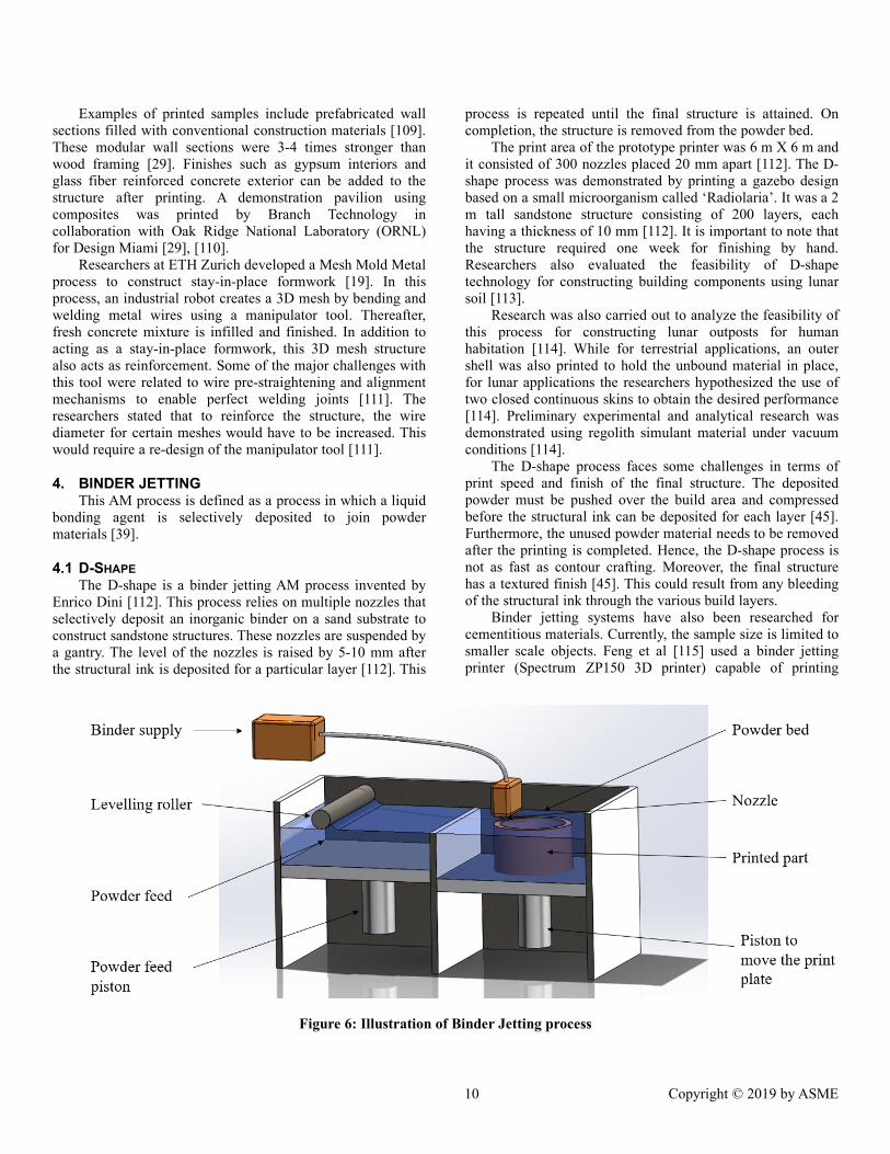
4. BINDER JETTING This AM process is defined as a process in which a liquid
bonding agent is selectively deposited to join powder materials [39].
4.1 D-SHAPE The D-shape is a binder jetting AM process invented by
Enrico Dini [112]. This process relies on multiple nozzles that selectively deposit an inorganic binder on a sand substrate to construct sandstone structures. These nozzles are suspended by a gantry. The level of the nozzles is raised by 5-10 mm after the structural ink is deposited for a particular layer [112]. This
process is repeated until the final structure is attained. On completion, the structure is removed from the powder bed.
The print area of the prototype printer was 6 m X 6 m and it consisted of 300 nozzles placed 20 mm apart [112]. The D-shape process was demonstrated by printing a gazebo design based on a small microorganism called ‘Radiolaria’. It was a 2 m tall sandstone structure consisting of 200 layers, each having a thickness of 10 mm [112]. It is important to note that the structure required one week for finishing by hand. Researchers also evaluated the feasibility of D-shape technology for constructing building components using lunar soil [113].
Research was also carried out to analyze the feasibility of this process for constructing lunar outposts for human habitation [114]. While for terrestrial applications, an outer shell was also printed to hold the unbound material in place, for lunar applications the researchers hypothesized the use of two closed continuous skins to obtain the desired performance [114]. Preliminary experimental and analytical research was demonstrated using regolith simulant material under vacuum conditions [114].
The D-shape process faces some challenges in terms of print speed and finish of the final structure. The deposited powder must be pushed over the build area and compressed before the structural ink can be deposited for each layer [45]. Furthermore, the unused powder material needs to be removed after the printing is completed. Hence, the D-shape process is not as fast as contour crafting. Moreover, the final structure has a textured finish [45]. This could result from any bleeding of the structural ink through the various build layers.
Binder jetting systems have also been researched for cementitious materials. Currently, the sample size is limited to smaller scale objects. Feng et al [115] used a binder jetting printer (Spectrum ZP150 3D printer) capable of printing
Figure 6: Illustration of Binder Jetting process
11 Copyright © 2019 by ASME
samples of dimension 356 mm (L) X 254 mm (W) X 203 mm (H). The material was a mixture of plaster powder ZP150 (comprising of plaster, vinyl polymer and carbohydrate) and a binder material (ZB60) consisting of humectant and water [115]. The load bearing capacity of the samples was found to be significantly dependent on build direction. Xia and Sanjayan [116] analyzed the printability of geopolymer-based material using different parameters such as particle size distribution, powder density and powder bed porosity to name a few. The prepared material consisted of a blend of slag, anhydrous sodium metasilicate and fine sand. All printed samples exhibited anisotropic mechanical properties and geometric accuracy. Better accuracy and greater strength were observed along the direction of binder jetting [116]. Researchers also developed a material for binder jetting using a mix of calcium aluminate cement that passed through 150 µm sieve and Portland cement [117]. A water-based binder was used for printing. The porosity of samples was found to dependent on particle size distribution and layer thickness. More research is required to develop binder jetting systems for large scale AM of concrete structures.
5. POWDER BED FUSION In this AM process, thermal energy is used to selectively
fuse regions of a powder bed [39]. Like binder jetting process, this process uses a powder bed system as shown in Figure . However, the powder is selectively melted using thermal energy.
5.1 SELECTIVE SEPARATION SINTERING This AM process uses two types of powders, a base
powder (B-powder) that constitutes the final part and a separator powder (S-powder) that is used as a separator [118]. As the name suggests, the role of the S-powder is to separate the part from the surrounding B-powder. Successful implementation of this process is highly dependent on these powders having significantly different sintering temperatures. The printing process starts with a uniform layer of B-powder on the bed. Thereafter, S-powder is selectively deposited on top of the B-powder using motion actuators and a piezo vibrator. This process is repeated until all the layers are complete. Thereafter, the green part is moved to the sintering surface where the sintering is carried out at a temperature that is higher than the sintering temperature of the B-powder, but lower than the sintering temperature of S-powder. Hence, the part comprising of the B-powder is well sintered whereas the loose S-powder is removed from the printed part.
Preliminary experiments were carried out to demonstrate this process for space applications using ceramics and metals [118], [119]. Bronze components were fabricated using alumina powder and tungsten powder as separators [118]. Additionally, lunar regolith simulant JSC-1A and Bronze were used as B-powder while alumina powder was used as S-powder [119]. In both cases, the sintered parts were separated easily.
Since the SSS is a relatively new process, significant research is required to develop process knowledge and the effect of various ambient conditions on print quality.
6. ADDITIONAL GAPS In addition to the process specific gaps discussed earlier,
there are additional challenges in the application of AM processes towards infrastructure construction. These challenges range from creating new materials, improving process knowledge and developing new standards to system-level integration, and design for AM processes in the construction industry.
Material development for AM processes is a significant challenge. Even though new AM processes have been developed, the conventional cementitious materials used are not sustainable. New, sustainable materials need to be developed for construction applications in the 21st century. These materials must exhibit high performance especially when exposed to harsh environmental conditions. Moreover, emerging materials need to be able to respond to various external stimuli. Such capabilities could enable the construction of self-healing structures. Computational models will be vital in developing these novel materials.
Considerable research effort is required to increase our process knowledge. Characterization of various material properties discussed earlier such as extrudability, buildability, rheology, drying and shrinkage needs to be performed for these emerging AM processes. Mechanical properties of the printed parts printed also need to be studied. Additionally, we need to further our understanding of the relation between process parameters (such as print speed, layer height and environmental conditions) and the final part quality. These processes need to be robust capable of performing in diverse environmental conditions. Hence, process repeatability needs to be established. Also, capability of AM processes to repair infrastructure remains to be determined.
Research is also required to address system-level challenges. One of the challenges in this field is of collaborative robotic or swarm printing. A description of swarm printing was provided by Pegna [120] as: “a large structure could conceivably be built by an army of mechanical ‘ants’, one grain of sand at a time”. These robots are either terrestrial or aerial. Drones have been used for assembling structures using foam bricks [52, 53] as well as to construct tensile structures such as rope bridges [54, 55]. Currently, constraints such as limited carrying capacity, high energy costs, system complexity and ability to sustain flight in various weather conditions represent major hurdles for these aerial robots. On the other hand, terrestrial robots have also been used for assembly [56, 57] and AM construction purposes [127]. The latter system referred to as Minibuilders, comprised of individual robots capable of on-site construction with various wall curvatures. Prototypes of cable suspended robots were also developed at MIT. These were referred to as the SpiderBot and the CableBot [128]. These robots were suspended using cables from stale high points. The feed

12 Copyright © 2019 by ASME
material was externalized i.e. it was provided by a separate tubing for the CableBot. In case of the SpiderBot, the material was carried on the end effector. Significant research is required to deploy such swarm systems in real-life construction applications. Additionally, swarm printing approach could also use biological systems. Researchers at MIT [128] used a swarm of silkworms to print on a flat template rather than creating a cocoon. Spatial scaffolding constraints were used to alter their natural behavior This scaffolding was digitally constructed using an algorithm based on environmental and biological constraints [128].
Space exploration has added another dimension of challenges for these AM processes. Recently, Made In Space, Inc. (U.S.) won the Guinness World Record for the ”longest printed non-assembled piece” which measured 37.7 m in length [134]. The part was manufactured using Made in Space’s Extended Structure Additive Manufacturing Machine (ESAMM). This machine relies on robotic manipulators to constantly reorient the part being printed [135]. ESAMM is central to the Archinaut technology platform/system developed by Made In Space that enables autonomous manufacturing and assembly in space [136]. For this
application, it is vital to construct durable structures in an efficient manner while using locally available materials.
Additionally, systems technology tools such as Build Information Modeling (BIM) are emerging. BIM models facilitate digital representation of a building for project communication over its entire life-cycle [137]. Synchrony of such tools with AM processes would enable construction professionals to take better, informed decisions. For example, these systems-technology tools could recommend construction materials, AM processes and machine parameters to achieve desired printing performance and design. These tools could also recommend on-site vs. off-site construction strategies. Such recommendations would account for environmental conditions, material and structural support requirements, budget, safety and other factors. While some exploration has been carried out for concrete structures in this case [138], significant progress is yet to be made.
The fast pace of experimental research in this field warrants the timely development of building codes and standards. Establishment of strength of materials would require the development of performance-based metrics as opposed to the current prescriptive standards. An example of
Figure 3: Knowledge gaps for AM processes for construction of infrastructure
13 Copyright © 2019 by ASME
such a performance-based metric would be, say, material ‘A’ should have property ‘P’ that exceeds a value ‘V’. This is different from prescriptive standards such as, ‘material A should be mixed with materials B and C in a, b and c proportions. Emerging research areas such as data informatics and tools such as Materials Genome Initiative could be vital resources in this field [140], [141]. Performance-based metrics coupled with a measurement science perspective should facilitate innovation in the field of material development. Additional examples of developing standards would include the designing custom test artifacts These artifacts would enable the engineers and architects to determine the suitability of materials and AM processes to achieve intended designs.
These emerging AM processes would also require a rethinking of the way we design buildings. New AM processes can facilitate complex stronger designs that use biomimicry to incorporate functionality and performance into the structural design of buildings. Currently, reinforcement remains a challenge for AM of cementitious structures. Bio-inspired designs could help address this challenge.
To realize the applications of AM processes in the construction industry, it is vital to have industry-academia collaboration. These collaborations could be pursued through small and medium scale joint ventures to construct infrastructure. Moreover, the broad spectrum of challenges warrants the need for interdisciplinary research. Capability of an AM process to print building 24 hours a day, 7 days a week would also require a new approach to logistics for construction industry.
7. CONCLUDING REMARKS AM processes for the construction of large-scale
infrastructure have been presented in this paper. The discussed processes include both current and emerging AM processes alongside respective research gaps. These AM processes are starting to find applications in demonstration projects. Evolution of AM processes for space exploration represent an important emerging application. Amongst emerging themes in AM processes, growth of collaborative robotics, ISRU and material development represent an opportunity for significant development. Additionally, improving process knowledge, incorporation of reinforcements, development of relevant codes and standards and industrial collaboration remain significant challenges. The breadth of these challenges warrants an interdisciplinary research collaboration of various disciplines ranging from engineering, architecture, sciences such as chemistry and roboticists. Future AM systems would be smart systems capable to pursue construction in an intelligent manner. These systems would be able to identify best construction methodologies to achieve the desired design, performance and functional objectives. In conclusion, AM processes are set to revolutionize the construction industry.
ACKNOWLEDGEMENTS We are thankful to Mr. Miguel Cervantes for assistance in processing the illustrations for the various processes.
REFERENCES
[1] B. P. Conner et al., “Making sense of 3-D printing: Creating a map of additive manufacturing products and services,” Addit. Manuf., vol. 1, pp. 64–76, 2014.
[2] B. Berman, “3-D printing: The new industrial revolution,” Bus. Horiz., vol. 55, no. 2, pp. 155–162, 2012.
[3] T. Birtchnell, J. Urry, C. Cook, and A. Curry, “Freight miles: the impact of 3D printing on transport and society.” Lancaster University, 2013.
[4] D. Espalin, D. W. Muse, E. MacDonald, and R. B. Wicker, “3D Printing multifunctionality: structures with electronics,” Int. J. Adv. Manuf. Technol., vol. 72, no. 5–8, pp. 963–978, 2014.
[5] E. Macdonald et al., “3D printing for the rapid prototyping of structural electronics,” IEEE Access, vol. 2, pp. 234–242, 2014.
[6] J. Parthasarathy, B. Starly, and S. Raman, “A design for the additive manufacture of functionally graded porous structures with tailored mechanical properties for biomedical applications,” J. Manuf. Process., vol. 13, no. 2, pp. 160–170, 2011.
[7] P. Heinl, L. Müller, C. Körner, R. F. Singer, and F. A. Müller, “Cellular Ti--6Al--4V structures with interconnected macro porosity for bone implants fabricated by selective electron beam melting,” Acta Biomater., vol. 4, no. 5, pp. 1536–1544, 2008.
[8] T. Wohlers, Wohlers report 2016. Wohlers Associates, Inc, 2016.
[9] Construction Intelligence Center, “Global Construction Outlook 2020,” 2015.
[10] International Labour Organization, “Facts on safety at work,” Int. Labor Off. Tech. Rep., 2005.
[11] NIST, “Metrics and Tools for Construction Productivity Project,” 2011. [Online]. Available: https://www.nist.gov/programs-projects/metrics-and-tools-construction-productivity-project. [Accessed: 03-Dec-2018].
[12] H. Nasir, H. Ahmed, C. Haas, and P. M. Goodrum, “An analysis of construction productivity differences between Canada and the United States,” Constr. Manag. Econ., vol. 32, no. 6, pp. 595–607, 2014.
[13] Bureau of Labor Statistics, “2016 U.S. Employment by Major Industry Sector.” [Online]. Available: https://www.bls.gov/emp/ep_table_201.htm. [Accessed: 18-Dec-2017].
[14] Bureau of Economic Analysis, “Gross Domestic Product by Industry: First Quarter 2016.” [Online]. Available: https://www.bea.gov/newsreleases/industry/gdpindustry/2016/gdpind116.htm. [Accessed: 18-Dec-2017].
[15] American Society of Civil Engineers, “Failure to Act,” Am. Soc. Civ. Eng., p. 32, 2016.
[16] N. A. of Engineering, “NAE Grand Challenges for Engineering,” 2008. [Online]. Available:

14 Copyright © 2019 by ASME
http://engineeringchallenges.org/challenges.aspx. [Accessed: 03-Dec-2018].
[17] N. A. of Engineering, “NAE Grand Challenges for Engineering.” [Online]. Available: http://engineeringchallenges.org/9136.aspx. [Accessed: 20-Apr-2018].
[18] R. Lab, “Think Formwork - Reduce Costs,” Structure Magazine, no. April, pp. 14–16, 2007.
[19] T. Wangler, E. Lloret, L. Reiter, N. Hack, F. Gramazio, and M. Kohler, “Digital Concrete : Opportunities and Challenges,” pp. 67–75, 2016.
[20] S. Bukkapatnam, J. Mander, S. Paal, Z. Pei, and L. Zeng, “Workshop Report - NSF Workshop on Additive Manufacturing (3D Printing) for Civil Infrastructure Design and Construction,” p. 34, 2017.
[21] I. Perkins and M. Skitmore, “Three-dimensional printing in the construction industry: A review,” Int. J. Constr. Manag., vol. 15, no. 1, pp. 1–9, 2015.
[22] F. Bos, R. Wolfs, Z. Ahmed, and T. Salet, “Additive manufacturing of concrete in construction: potentials and challenges of 3D concrete printing,” Virtual Phys. Prototyp., vol. 11, no. 3, pp. 209–225, 2016.
[23] Y. W. D. Tay, B. Panda, S. C. Paul, N. A. Noor Mohamed, M. J. Tan, and K. F. Leong, “3D printing trends in building and construction industry: a review,” Virtual Phys. Prototyp., vol. 12, no. 3, pp. 261–276, 2017.
[24] P. Wu, J. Wang, and X. Wang, “A critical review of the use of 3-D printing in the construction industry,” Autom. Constr., vol. 68, pp. 21–31, 2016.
[25] N. Labonnote, A. Rønnquist, B. Manum, and P. Rüther, “Additive construction: State-of-the-art, challenges and opportunities,” Autom. Constr., vol. 72, pp. 347–366, 2016.
[26] C. C. Corporation, “Contour Crafting Corporation.” [Online]. Available: http://contourcrafting.com/.
[27] B. Khoshnevis, “Large Scale 3-D Printing: Past, Present and Future Project,” 2017. [Online]. Available: https://static.tti.tamu.edu/conferences/tamu-engineering/nsf-3dp-workshop/day1/invited-talks-2/khoshnevis.pdf. [Accessed: 10-Oct-2017].
[28] B. Technology, “Branch Technology.” [Online]. Available: https://www.branch.technology. [Accessed: 01-Oct-2017].
[29] R. Platt Boyd IV, “Cellular Fabrication- 3-D Printing at Architectural Scale,” 2017. [Online]. Available: https://static.tti.tamu.edu/conferences/tamu-engineering/nsf-3dp-workshop/day1/invited-talks-1/boyd.pdf. [Accessed: 10-Oct-2017].
[30] “Genesis Dimensions.” [Online]. Available: https://www.genesisdimensions.com.
[31] K. Steinhauer, “Bringing Additive Manufacturing to the Construction Site,” 2017. [Online]. Available: https://static.tti.tamu.edu/conferences/tamu-engineering/nsf-3dp-workshop/day1/invited-talks-1/steinhauer.pdf. [Accessed: 10-Oct-2017].
[32] Winsun, “Winsun.” [Online]. Available: http://www.winsun3d.com/En/About/#abM1.
[33] Winsun, “The Future of Construction-WinSun.” [Online]. Available: file:///C:/Users/abhin/Downloads/Future_of_Construction_Cases_2016_WINSUN.pdf.
[34] CyBe, “CyBe.” [Online]. Available: https://cybe.eu/#section4.
[35] XtreE, “XtreE.” [Online]. Available: https://www.xtreee.eu/.
[36] “Apis Cor,” 2016. [Online]. Available: http://apis-cor.com/en/faq/texnicheskie-xarakteristiki-3d-printera/. [Accessed: 12-Oct-2017].
[37] (Fastbrick Robotics), “Fastbrick Robotics.” [Online]. Available: https://www.fbr.com.au/.
[38] MX3D, “MX3D.” [Online]. Available: http://mx3d.com/about/.
[39] A. ISO/ASTM52900-15, “Standard Terminology for Additive Manufacturing – General Principles – Terminology,” ASTM Int., 2015.
[40] B. Khoshnevis and R. Dutton, “Innovative rapid prototyping process makes large sized, smooth surfaced complex shapes in a wide variety of materials,” Mater. Technol., vol. 13, no. 2, pp. 53–56, 1998.
[41] B. Zareiyan and B. Khoshnevis, “Interlayer adhesion and strength of structures in Contour Crafting - Effects of aggregate size, extrusion rate, and layer thickness,” Autom. Constr., vol. 81, no. August 2016, pp. 112–121, 2017.
[42] D. Hwang and B. Khoshnevis, “An Innovative Construction Process-Contour Crafting,” 22nd Int. Symp. Autom. Robot. Constr. ISARC, 2005.
[43] D. Hwang and B. Khoshnevis, “Concrete Wall Fabrication by Contour Crafting,” ISAR 2004 21st Int. Symp. Autom. Robot. Constr., 2004.
[44] S. Lim, R. A. Buswell, T. T. Le, S. A. Austin, A. G. F. Gibb, and T. Thorpe, “Developments in construction-scale additive manufacturing processes,” Autom. Constr., vol. 21, pp. 262–268, 2012.
[45] S. Lim, R. A. Buswell, T. T. Le, S. A. Austin, A. G. F. Gibb, and T. Thorpe, “Developments in construction-scale additive manufacturing processes,” Autom. Constr., vol. 21, no. 1, pp. 262–268, 2012.
[46] H. Kwon, S. Bukkapatnam, B. Khoshnevis, and J. Saito, “Effects of orifice shape in contour crafting of ceramic materials,” Rapid Prototyp. J., vol. 8, no. 3, pp. 147–160, 2002.
[47] B. Khoshnevis, X. Yuan, B. Zahiri, J. Zhang, and B. Xia, “Construction by Contour Crafting using sulfur concrete with planetary applications,” Rapid Prototyp. J., vol. 22, no. 5, pp. 848–856, 2016.
[48] S. Bukkapatnam and B. Clark, “Dynamic Modeling and Monitoring of Contour Crafting—An Extrusion-Based Layered Manufacturing Process,” J. Manuf. Sci. Eng., vol. 129, no. 1, p. 135, 2007.
15 Copyright © 2019 by ASME
[49] T. Di Carlo, “Experimental and Numerical Techniques To Characterize Structural Properties of Fresh Concrete Relevant To Contour Crafting,” no. December, 2012.
[50] S. Bukkapatnam, B. Khoshnevis, H. Kwon, and J. Saito, “Experimental investigation of contour crafting using ceramics materials,” Rapid Prototyp. J., vol. 7, no. 1, pp. 32–42, 2001.
[51] ASTM, “Standard Terminology Relating to Concrete and Concrete Aggregates 1,” pp. 1–8, 2018.
[52] A. Kazemian, X. Yuan, E. Cochran, and B. Khoshnevis, “Cementitious materials for construction-scale 3D printing: Laboratory testing of fresh printing mixture,” Constr. Build. Mater., vol. 145, pp. 639–647, 2017.
[53] B. Khoshnevis, “Automated construction by contour crafting - Related robotics and information technologies,” Autom. Constr., vol. 13, no. 1, pp. 5–19, 2004.
[54] H. Kwon, “Experimentation and Analysis of Contour Crafting (CC) Process Using Uncured Ceramic Materials,” no. August, p. 213, 2002.
[55] J. Zhang and B. Khoshnevis, “Optimal machine operation planning for construction by Contour Crafting,” Autom. Constr., vol. 29, pp. 50–67, 2013.
[56] J. Zhang and B. Khoshnevis, “Contour Crafting Process Plan Optimization Part I : Single-Nozzle Case,” J. Ind. Syst. Eng., vol. 4, no. 1, pp. 33–46, 2010.
[57] J. Zhang, “Contour Crafting Process Planning and Optimization,” University of Southern California, 2009.
[58] Z. Yeh and B. Khoshnevis, “Geometric conformity analysis for automated fabrication processes generating ruled surfaces: demonstration for contour crafting,” Rapid Prototyp. J., vol. 15, no. 5, pp. 361–369, 2009.
[59] B. Zareiyan and B. Khoshnevis, “Effects of interlocking on interlayer adhesion and strength of structures in 3D printing of concrete,” Autom. Constr., vol. 83, no. August, pp. 212–221, 2017.
[60] P. Bosscher, R. L. Williams, L. S. Bryson, and D. Castro-Lacouture, “Cable-suspended robotic contour crafting system,” Autom. Constr., vol. 17, no. 1, pp. 45–55, 2007.
[61] R. L. W. Ii, M. Xin, and P. Bosscher, “DETC2008-49478,” pp. 1–8, 2018.
[62] J. Good, S. Gilley, C. McLemore, J. Fikes, and C. Darby, “Fabrication Capabilities Utilizing in Situ Materials,” AIAA Sp. 2008 Conf. Expo., no. September, pp. 1–6, 2008.
[63] B. Khoshnevis et al., “Lunar contour crafting - A novel technique for ISRU-based habitat development,” 43rd AIAA Aerosp. Sci. Meet. Exhib. - Meet. Pap., no. January, pp. 1–13, 2005.
[64] M. Khoshnevis, Behrokh; Carlson, Anders; Leach,
Neil; Thangavelu, “Contour Crafting Simulation Plan for Lunar Settlement Infrastructure Buildup,” Earth Sp. 2012, no. Thangavelu 2000, pp. 1458–1467, 2012.
[65] N. Leach, A. Carlson, B. Khoshnevis, and M. Thangavelu, “Robotic Construction by Contour Crafting: The Case of Lunar Construction,” Int. J. Archit. Comput., vol. 10, no. 3, pp. 423–438, 2012.
[66] B. Khoshnevis, M. Thangavelu, X. Yuan, and J. Zhang, “Advances in Contour Crafting Technology for Extraterrestrial Settlement Infrastructure Buildup,” Aiaa, vol. 5438, pp. 10–12, 2013.
[67] M. Thangavelu, B. Khoshnevis, A. Carlson, and N. Leach, “Architectural Concepts Employing Co-Robot Strategy and Contour Crafting Technologies for Lunar Settlement Infrastructure Development,” AIAA Sp. 2012 Conf. Expo., no. September, pp. 1–29, 2012.
[68] G. B. Sanders and W. E. Larson, “Integration of in-situ resource utilization into lunar/mars exploration through field analogs,” Adv. Sp. Res., vol. 47, no. 1, pp. 20–29, 2011.
[69] R. P. Mueller et al., “Automated Additive Construction (AAC) for Earth and Space Using In-situ Resources,” Proc. Fifteenth Bienn. ASCE Aerosp. Div. Int. Conf. Eng. Sci. Constr. Oper. Challenging Environ. (Earth Sp. 2016), 2016.
[70] S. Lim et al., “Development of a viable concrete printing process,” in Proceedings of the 28th International Symposium on Automation and Robotics in Construction, (ISARC2011), Seoul, South Korea, 2011, pp. 665–670.
[71] T. T. Le, S. A. Austin, S. Lim, R. A. Buswell, A. G. F. Gibb, and T. Thorpe, “Mix design and fresh properties for high-performance printing concrete,” pp. 1221–1232, 2012.
[72] ASTM, “ASTM C125-18 Standard Terminology Relating to Concrete and Concrete Aggregates,” pp. 1–4, 2018.
[73] T. S. Rushing et al., “Investigation of concrete mixtures for additive construction,” Rapid Prototyp. J., vol. 23, no. 1, pp. 74–80, 2017.
[74] Z. Malaeb, H. Hachem, A. Tourbah, T. Maalouf, N. El Zarwi, and F. Hamzeh, “3D Concrete Printing: Machine and Mix Design,” Int. J. Civ. Eng. Technol., vol. 6, no. April, pp. 14–22, 2015.
[75] M. Hambach and D. Volkmer, “Properties of 3D-printed fiber-reinforced Portland cement paste,” Cem. Concr. Compos., vol. 79, pp. 62–70, 2017.
[76] B. Panda, S. C. Paul, N. A. N. Mohamed, Y. W. D. Tay, and M. J. Tan, “Measurement of tensile bond strength of 3D printed geopolymer mortar,” Meas. J. Int. Meas. Confed., vol. 113, no. September 2017, pp. 108–116, 2018.
[77] B. Panda, S. C. Paul, L. J. Hui, Y. W. D. Tay, and M. J. Tan, “Additive manufacturing of geopolymer for sustainable built environment,” J. Clean. Prod., vol. 167, pp. 281–288, 2018.

16 Copyright © 2019 by ASME
[78] T. A. M. Salet, F. P. Bos, R. J. M. Wolfs, and Z. Y. Ahmed, “3D concrete printing - A structural engineering perspective,” High Tech Concr. Where Technol. Eng. Meet, pp. xliii–lvii, 2017.
[79] B. Panda and M. J. Tan, “Experimental study on mix proportion and fresh properties of fly ash based geopolymer for 3D concrete printing,” Ceram. Int., vol. 44, no. 9, pp. 10258–10265, 2018.
[80] S. C. Paul, Y. W. D. Tay, B. Panda, and M. J. Tan, “Fresh and hardened properties of 3D printable cementitious materials for building and construction,” Arch. Civ. Mech. Eng., vol. 18, no. 1, pp. 311–319, 2018.
[81] L. Feng and L. Yuhong, “Study on the Status Quo and Problems of 3D Printed Buildings in China,” Glob. J. HUMAN-SOCIAL Sci., vol. 14, no. 5, 2014.
[82] V. N. Nerella, M. Krause, M. Näther, and V. Mechtcherine, “Studying printability of fresh concrete for formwork free Concrete on-site 3D Printing technology technology (CONPrint3D),” Rheol. Messungen an Baustoffen, no. March, pp. 236–246, 2016.
[83] C. Gosselin, R. Duballet, P. Roux, N. Gaudillière, J. Dirrenberger, and P. Morel, “Large-scale 3D printing of ultra-high performance concrete - a new processing route for architects and builders,” Mater. Des., vol. 100, pp. 102–109, 2016.
[84] A. Perrot, D. Rangeard, and A. Pierre, “Structural built-up of cement-based materials used for 3D-printing extrusion techniques,” Mater. Struct. Constr., vol. 49, no. 4, pp. 1213–1220, 2016.
[85] W. A. S. P. (WASP, “DeltaWASP 2040.” [Online]. Available: https://www.personalfab.it/en/shop/delta-printer-deltawasp-20-40/.
[86] J. Xu, L. Ding, and P. E. D. Love, “Digital reproduction of historical building ornamental components: From 3D scanning to 3D printing,” Autom. Constr., vol. 76, pp. 85–96, 2017.
[87] E. Lloret et al., “Complex concrete structures: Merging existing casting techniques with digital fabrication,” CAD Comput. Aided Des., vol. 60, pp. 40–49, 2015.
[88] P. D. Zavattieri, “Material Architecture Inspired by Nature: Harnessing the Role of Interfaces and Uncovering Hidden Possibilities,” 2017. [Online]. Available: https://static.tti.tamu.edu/conferences/tamu-engineering/nsf-3dp-workshop/day1/invited-talks-2/zavattieri.pdf. [Accessed: 10-Oct-2017].
[89] W. Gao et al., “The status, challenges, and future of additive manufacturing in engineering,” Comput. Des., vol. 69, pp. 65–89, 2015.
[90] G. Habert, “Environmental impact of Portland cement production,” Eco-efficient Concr. F. Pacheco-Torgal, S. Jalali, J. Labrincha, VM John (ed.), Woodhead Publ. Cambridge, pp. 3–25, 2013.
[91] T. (Theo) Salet, “3D Concrete Printing – A Journey
with Destination Unknown,” 2017. [Online]. Available: https://static.tti.tamu.edu/conferences/tamu-engineering/nsf-3dp-workshop/day1/invited-talks-3/salet.pdf. [Accessed: 10-Oct-2017].
[92] T. Wangler, “Materials Challenges in Digital Fabrication with Concrete,” 2017. [Online]. Available: https://static.tti.tamu.edu/conferences/tamu-engineering/nsf-3dp-workshop/day2/invited-talks-1/wangler.pdf. [Accessed: 11-Oct-2017].
[93] S. Z. Jones, “NIST Perspectives on Additive Manufacturing for Civil Infrastructure Design and Construction,” 2017. [Online]. Available: https://static.tti.tamu.edu/conferences/tamu-engineering/nsf-3dp-workshop/day2/invited-talks-2/jones.pdf. [Accessed: 11-Oct-2017].
[94] J. J. Biernacki et al., “Cements in the 21st century: Challenges, perspectives, and opportunities,” J. Am. Ceram. Soc., vol. 100, no. 7, pp. 2746–2773, 2017.
[95] F. Sanchez, J. J. Biernacki, J. Olek, and P. D. Zavattieri, “3D Printing: A New Promising Avenue for Concrete and the Construction Industry.” 2017.
[96] J. J. Biernacki et al., “Cements in the 21 st century: challenges, perspectives, and opportunities,” J. Am. Ceram. Soc., no. March, pp. 1–28, 2017.
[97] M. J. H. Wijffels, R. J. M. Wolfs, A. S. J. Suiker, and T. A. M. Salet, “Magnetic orientation of steel fibres in self-compacting concrete beams: Effect on failure behaviour,” Cem. Concr. Compos., vol. 80, no. April, pp. 342–355, 2017.
[98] S. J. Keating, J. C. Leland, L. Cai, and N. Oxman, “Toward site-specific and self-sufficient robotic fabrication on architectural scales,” Sci. Robot., vol. 2, no. 5, p. eaam8986, 2017.
[99] Reuters, “3D-printed public housing unveiled in France.” [Online]. Available: https://www.reuters.com/article/us-france-robot-printer-house/3d-printed-public-housing-unveiled-in-france-idUSKBN1HH2HW.
[100] Y. Miyamoto, W. A. Kaysser, B. H. Rabin, A. Kawasaki, and R. G. Ford, Eds., Functionally Graded Materials: Design, Processing and Applications Volume 5 of Materials Technology Series. Springer Science & Business Media, 2013.
[101] J. Duro-Royo, L. Mogas-Soldevila, and N. Oxman, “Flow-based fabrication: An integrated computational workflow for design and digital additive manufacturing of multifunctional heterogeneously structured objects,” CAD Comput. Aided Des., vol. 69, pp. 143–154, 2015.
[102] L. Mogas-Soldevila, J. Duro-Royo, and N. Oxman, “Water-Based Robotic Fabrication: Large-Scale Additive Manufacturing of Functionally Graded Hydrogel Composites via Multichamber Extrusion,” 3D Print. Addit. Manuf., vol. 1, no. 3, pp. 141–151, 2014.
[103] C. E. Duty et al., “Structure and mechanical behavior

17 Copyright © 2019 by ASME
of Big Area Additive Manufacturing (BAAM) materials,” Rapid Prototyp. J., vol. 23, no. 1, pp. 181–189, 2017.
[104] C. E. Duty et al., “Structure and mechanical behavior of Big Area Additive Manufacturing ( BAAM ) materials,” 2017.
[105] “ORNL/Boeing Guinness World Record,” 2016. . [106] K. Biswas et al., “Additive Manufacturing Integrated
Energy—Enabling Innovative Solutions for Buildings of the Future,” J. Sol. Energy Eng., vol. 139, no. 1, p. 015001, 2016.
[107] L. J. Love et al., “The importance of carbon fiber to polymer additive manufacturing,” J. Mater. Res., vol. 29, no. 17, pp. 1893–1898, 2014.
[108] C. Newell et al., “Out of Bounds Additive Manufacturing.”
[109] B. Technology, “Branch Technology.” [Online]. Available: https://www.branch.technology/.
[110] B. K. Post, “Breaking Barriers with BAAM: Large Scale Additive Manufacturing Applications in Infrastructure,” 2017. [Online]. Available: https://static.tti.tamu.edu/conferences/tamu-engineering/nsf-3dp-workshop/day1/invited-talks-2/post.pdf. [Accessed: 10-Oct-2017].
[111] N. Hack, W. V. Lauer, F. Gramazio, and M. Kohler, “Mesh Mould: Robotically Fabricated Metal Meshes as Concrete Formwork and Reinforcement,” Proc. 11th Int. Symp. Ferrocem. 3rd ICTRC Int. Conf. Text. Reinf. Concr., pp. 347–359, 2015.
[112] E. Dini, “D-SHAPE - The 21st century revolution in building technology has a name.,” pp. 1–16, 2009.
[113] G. Cesaretti, E. Dini, X. De Kestelier, V. Colla, and L. Pambaguian, “Building components for an outpost on the Lunar soil by means of a novel 3D printing technology,” Acta Astronaut., vol. 93, pp. 430–450, 2014.
[114] G. Cesaretti, E. Dini, X. De Kestelier, V. Colla, and L. Pambaguian, “Building components for an outpost on the Lunar soil by means of a novel 3D printing technology,” Acta Astronaut., vol. 93, pp. 430–450, 2014.
[115] P. Feng, X. Meng, J.-F. Chen, and L. Ye, “Mechanical properties of structures 3D printed with cementitious powders,” Constr. Build. Mater., vol. 93, pp. 486–497, 2015.
[116] M. Xia and J. Sanjayan, “Method of formulating geopolymer for 3D printing for construction applications,” Mater. Des., vol. 110, pp. 382–390, 2016.
[117] P. Shakor, J. Sanjayan, A. Nazari, and S. Nejadi, “Modified 3D printed powder to cement-based material and mechanical properties of cement scaffold used in 3D printing,” Constr. Build. Mater., vol. 138, pp. 398–409, 2017.
[118] J. Zhang and B. Khoshnevis, “Selective Separation Sintering ( SSS ) A New Layer Based Additive
Manufacturing Approach for Metals and Ceramics,” Proc. Solid Free. Fabr. Symp., pp. 71–79, 2015.
[119] B. Khoshnevis and J. Zhang, “Selective Separation Sintering (SSS) - An Additive Manufacturing Approach for Fabrication of Ceramic and Metallic Parts with Application in Planetary Construction,” AIAA Sp. 2015 Conf. Expo., 2015.
[120] J. Pegna, “Exploratory investigation of solid freeform construction,” Autom. Constr., vol. 5, no. 5, pp. 427–437, 1997.
[121] Q. Lindsey and V. Kumar, Distributed construction of truss structures. 2013.
[122] F. Augugliaro et al., “The flight assembled architecture installation: Cooperative contruction with flying machines,” IEEE Control Syst., vol. 34, no. 4, pp. 46–64, 2014.
[123] A. Mirjan, F. Gramazio, M. Kohler, F. Augugliaro, R. D', and Andrea, “Architectural fabrication of tensile structures with flying machines: BT - Green Design, Materials and Manufacturing Processes,” Green Des. Mater. Manuf. Process., pp. 513–518, 2013.
[124] F. Augugliaro, A. Mirjan, F. Gramazio, M. Kohler, and R. D’Andrea, “Building tensile structures with flying machines,” IEEE Int. Conf. Intell. Robot. Syst., pp. 3487–3492, 2013.
[125] T. Sandy, M. Giftthaler, K. Dorfler, M. Kohler, and J. Buchli, “Autonomous repositioning and localization of an in situ fabricator,” Proc. - IEEE Int. Conf. Robot. Autom., vol. 2016–June, no. Icra, pp. 2852–2858, 2016.
[126] M. Giftthaler et al., “Mobile Robotic Fabrication at 1:1 scale: the In situ Fabricator,” pp. 1–11, 2017.
[127] S. Jokić et al., “Robotic positioning device for three-dimensional printing,” arXiv Prepr. arXiv 1406.3400, pp. 1–14, 2014.
[128] J. Duro-royo, E. Tsai, J. Duro-royo, S. Keating, B. Peters, and E. Tsai, “Towards Robotic Swarm,” pp. 108–115.
[129] J.-M. Gosau, “Regolith stabilization and building materials for the lunar surface,” Earth Sp., p. 243, 2012.
[130] M. B. Barmatz, D. E. Steinfeld, D. Winterhalter, D. L. Rickman, and M. a. Weinstein, “Microwave Heating Studies and Instrumentation for Processing Lunar Regolith and Simulants,” 44th Lunar Planet. Sci. Conf., vol. 51, p. 1223, 2013.
[131] M. Barmatz, D. Steinfeld, M. Anderson, and D. Winterhalter, “3D Microwave Print Head Approach for Processing Lunar and Mars Regolith,” 45th Lunar Planet. Sci. Conf., pp. 3–4, 2014.
[132] T. Nakamura and C. L. Senior, “Solar Thermal Power for Lunar Materials Processing,” J. Aerosp. Eng., vol. 21, no. 2, pp. 91–101, 2008.
[133] T. Nakamura and B. K. Smith, “Solar Thermal System for Lunar ISRU Applications: Development and Field

18 Copyright © 2019 by ASME
Operation at Mauna Kea, HI,” Proc. SPIE - Nonimaging Opt. Effic. Des. Illum. Sol. Conc., vol. 8124, no. VIII, p. 0B, 2011.
[134] G. W. Records, “Guinness Record: Made In Space.” . [135] Made In Space, “Extended Structure Additive
Manufacturing Machine.” [Online]. Available: http://madeinspace.us/projects/esamm/.
[136] M. I. Space, “Archinaut.” [Online]. Available: http://madeinspace.us/archinaut/.
[137] T. Cerovsek, “A review and outlook for a ‘Building Information Model’ (BIM): A multi-standpoint framework for technological development,” Adv. Eng. Informatics, vol. 25, no. 2, pp. 224–244, 2011.
[138] R. Duballet, O. Baverel, and J. Dirrenberger,
“Classification of building systems for concrete 3D printing,” Autom. Constr., vol. 83, no. August, pp. 247–258, 2017.
[139] T. T. Le et al., “Hardened properties of high-performance printing concrete,” Cem. Concr. Res., vol. 42, no. 3, pp. 558–566, 2012.
[140] D. J. Goodings, “NSF Perspectives on Additive Manufacturing for Civil Infrastructure Design and Construction,” 2017. [Online]. Available: https://static.tti.tamu.edu/conferences/tamu-engineering/nsf-3dp-workshop/day2/invited-talks-2/goodings.pdf. [Accessed: 11-Oct-2017].
[141] C. Kalil Tom And Wadia, “Materials Genome Initiative for Global Competitiveness,” 2011.