a lean view of chained metal additive manufacturing and cnc machining processes
TRANSCRIPT
15MMP501
MSc MAJOR PROJECT (FULL TIME)
A LEAN VIEW OF CHAINED METAL ADDITIVE MANUFACTURING AND CNC
MACHINING PROCESSES
FINAL REPORT
2016
THEODOROS PANAGIOTIDIS
B512066
Supervisor: Robert Wood
2nd Reader: Pedro Ferreira

2
Certificate of Originality
This is to certify that I am responsible for the work submitted in this report, that
the original work is my own except as specified in acknowledgements or in
footnotes or in any other way. I also certify that this work has not been
submitted previously to this or any other institution, for any other purpose.
_________________________ (signed)
_________________________ (date)
3
Table of Contents
Certificate of Originality .................................................................................... 2
Table of Contents ............................................................................................. 3
Abstract ............................................................................................................ 5
1. Introduction ............................................................................................... 6
2. Classification of Manufacturing Processes ............................................... 9
2.1 Various process classifications in the literature .................................. 9
2.2 Leo Alting’s classification of Manufacturing Processes ................... 9
3. Modelling Method and Knowledge Mapping ........................................... 10
4. Review of selected paradigms ................................................................ 12
4.1 Computer Numerical Control ............................................................ 12
4.2 Subtractive Manufacturing ................................................................ 13
4.3 Additive Manufacturing ..................................................................... 14
4.4 Lean Manufacturing .......................................................................... 15
5. Hybrid Manufacturing .............................................................................. 16
5.1 Introduction ........................................................................................... 16
5.2 Review of Hybrid Manufacturing Systems/Technology ........................ 16
6. Hybrid Machine Modelling and Analysis ................................................. 18
6.1 Overview .............................................................................................. 18
6.2 Computer Numerical Control System ................................................... 18
Introduction ............................................................................................. 18
6.2.1 CNC Controller .............................................................................. 18
6.2.2 Feed Drive System ........................................................................ 20
6.2.3 Spindle System .............................................................................. 26
6.3 Machining System ................................................................................ 26
Introduction ............................................................................................. 26
6.3.1 Tool Holding System ...................................................................... 27
6.3.2 Coolant Supply System.................................................................. 31
6.3.3 Cutting Tool ................................................................................... 33
6.4 Directed Energy Deposition System ..................................................... 36
Introduction ............................................................................................. 36
6.4.1 Laser System ................................................................................. 37
6.4.2 Powder and Gas Delivery System ................................................. 41
6.4.3 Cladding Nozzle System ................................................................ 42
4
7. Hybrid manufacturing parameters and physics ....................................... 44
7.1 Overview .............................................................................................. 44
7.2 Mechanical Cutting [56] .......................................................................... 44
7.2.1 Important parameters..................................................................... 44
7.2.2 Important physical phenomena ...................................................... 51
7.3 Laser Cladding [59] ................................................................................ 52
7.3.1 Important parameters..................................................................... 52
7.3.2 Important physical phenomena ...................................................... 54
8. A Lean View of Hybrid Manufacturing ..................................................... 56
8.1 Introduction ........................................................................................... 56
8.2 A novel approach ................................................................................. 56
8.3 Hybrid is Lean ...................................................................................... 57
8.3.1 Introduction .................................................................................... 57
8.3.2 Seven Wastes: Traditional vs. Hybrid processes ........................... 58
8.4 Hybrid Can Be Leaner .......................................................................... 61
8.4.1 Introduction .................................................................................... 61
8.4.2 Identifying Wastes in Hybrid Systems ............................................ 61
8.4.3 Waste Table Review ...................................................................... 66
9. Discussion .............................................................................................. 68
10. Conclusion & Future Work ................................................................... 69
11. References ........................................................................................... 70
Appendices .................................................................................................... 77
Acknowledgements ........................................................................................ 78
5
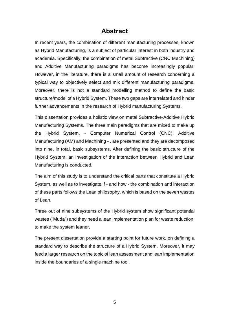
Abstract
In recent years, the combination of different manufacturing processes, known
as Hybrid Manufacturing, is a subject of particular interest in both industry and
academia. Specifically, the combination of metal Subtractive (CNC Machining)
and Additive Manufacturing paradigms has become increasingly popular.
However, in the literature, there is a small amount of research concerning a
typical way to objectively select and mix different manufacturing paradigms.
Moreover, there is not a standard modelling method to define the basic
structure/model of a Hybrid System. These two gaps are interrelated and hinder
further advancements in the research of Hybrid manufacturing Systems.
This dissertation provides a holistic view on metal Subtractive-Additive Hybrid
Manufacturing Systems. The three main paradigms that are mixed to make up
the Hybrid System, - Computer Numerical Control (CNC), Additive
Manufacturing (AM) and Machining - , are presented and they are decomposed
into nine, in total, basic subsystems. After defining the basic structure of the
Hybrid System, an investigation of the interaction between Hybrid and Lean
Manufacturing is conducted.
The aim of this study is to understand the critical parts that constitute a Hybrid
System, as well as to investigate if - and how - the combination and interaction
of these parts follows the Lean philosophy, which is based on the seven wastes
of Lean.
Three out of nine subsystems of the Hybrid system show significant potential
wastes (“Muda”) and they need a lean implementation plan for waste reduction,
to make the system leaner.
The present dissertation provide a starting point for future work, on defining a
standard way to describe the structure of a Hybrid System. Moreover, it may
feed a larger research on the topic of lean assessment and lean implementation
inside the boundaries of a single machine tool.
6
1. Introduction
The emerging trends as well as the challenges and opportunities in global
Manufacturing of the 21th century, push industries to develop flexible and
efficient manufacturing systems. Today, the combination of metal Additive and
Subtractive Manufacturing has become an object of research in both academia
and industry, mainly, due to the complementary nature of these two
technologies. Another manufacturing paradigm that drives the global
manufacturing is “Lean Manufacturing”, which leads to production optimization
with substantial minimization of various types of “Muda” - wastes (like
overproduction, over-processing, motion, etc.).
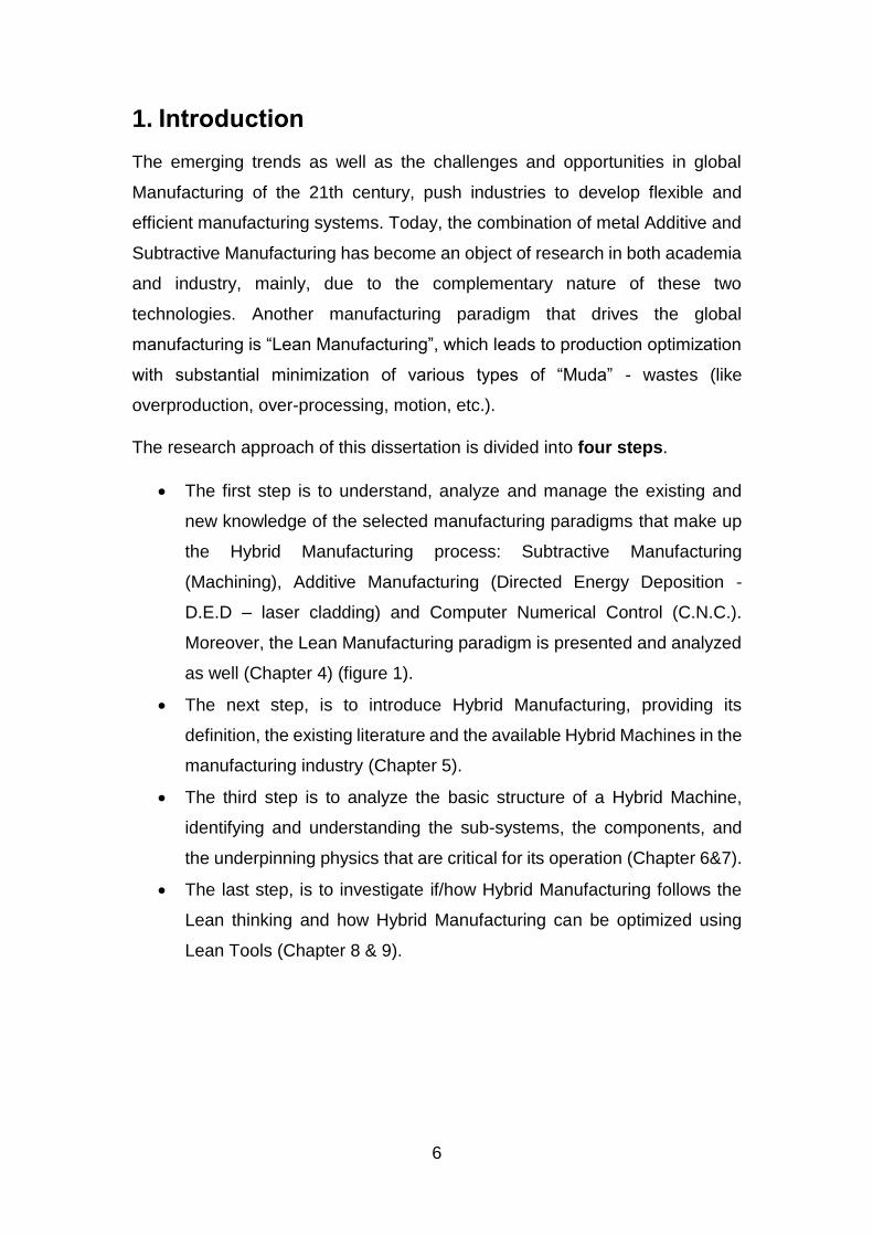
The research approach of this dissertation is divided into four steps.
The first step is to understand, analyze and manage the existing and
new knowledge of the selected manufacturing paradigms that make up
the Hybrid Manufacturing process: Subtractive Manufacturing
(Machining), Additive Manufacturing (Directed Energy Deposition -
D.E.D – laser cladding) and Computer Numerical Control (C.N.C.).
Moreover, the Lean Manufacturing paradigm is presented and analyzed
as well (Chapter 4) (figure 1).
The next step, is to introduce Hybrid Manufacturing, providing its
definition, the existing literature and the available Hybrid Machines in the
manufacturing industry (Chapter 5).
The third step is to analyze the basic structure of a Hybrid Machine,
identifying and understanding the sub-systems, the components, and
the underpinning physics that are critical for its operation (Chapter 6&7).
The last step, is to investigate if/how Hybrid Manufacturing follows the
Lean thinking and how Hybrid Manufacturing can be optimized using
Lean Tools (Chapter 8 & 9).
7
Figure 1: The subject of this project; A Lean view of Hybrid Manufacturing.
Hybrid Manufacturing
Hybrid Manufacturing is a new manufacturing paradigm, very popular in 21st
century. It is, simplistically, the combination of different manufacturing
processes [1]. Although, as “Hybrid” can be considered any combination of two
or more processes, it has become usual, nowadays, to refer as “Hybrid
Manufacturing”, the combination of Subtractive and Additive Manufacturing.
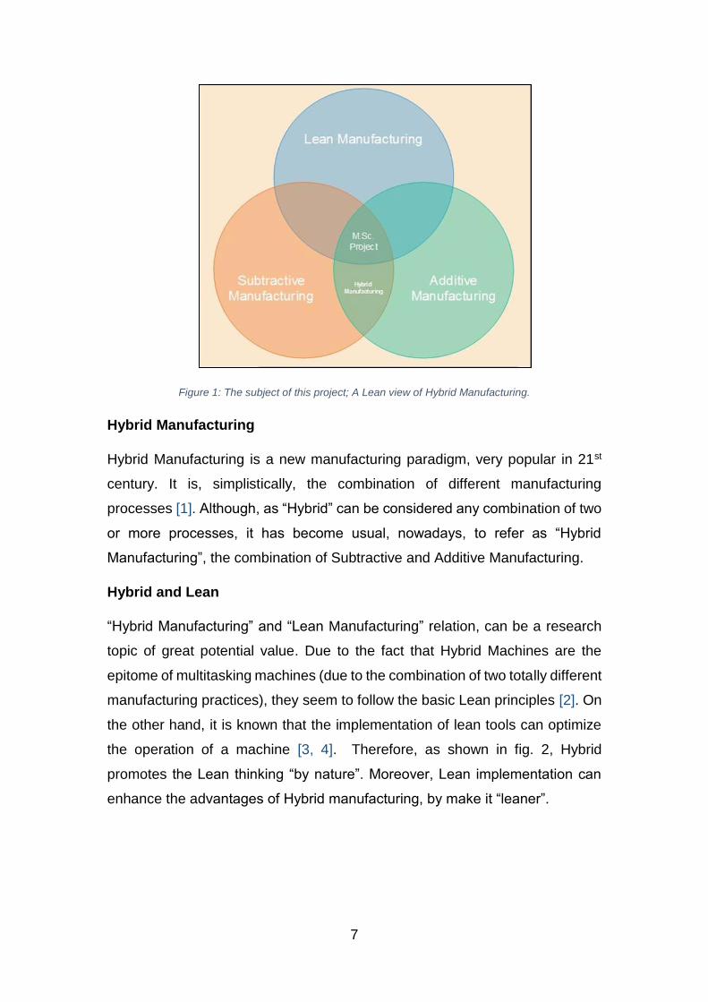
Hybrid and Lean
“Hybrid Manufacturing” and “Lean Manufacturing” relation, can be a research
topic of great potential value. Due to the fact that Hybrid Machines are the
epitome of multitasking machines (due to the combination of two totally different
manufacturing practices), they seem to follow the basic Lean principles [2]. On
the other hand, it is known that the implementation of lean tools can optimize
the operation of a machine [3, 4]. Therefore, as shown in fig. 2, Hybrid
promotes the Lean thinking “by nature”. Moreover, Lean implementation can
enhance the advantages of Hybrid manufacturing, by make it “leaner”.
8
Figure 2: Hybrid and Lean interaction
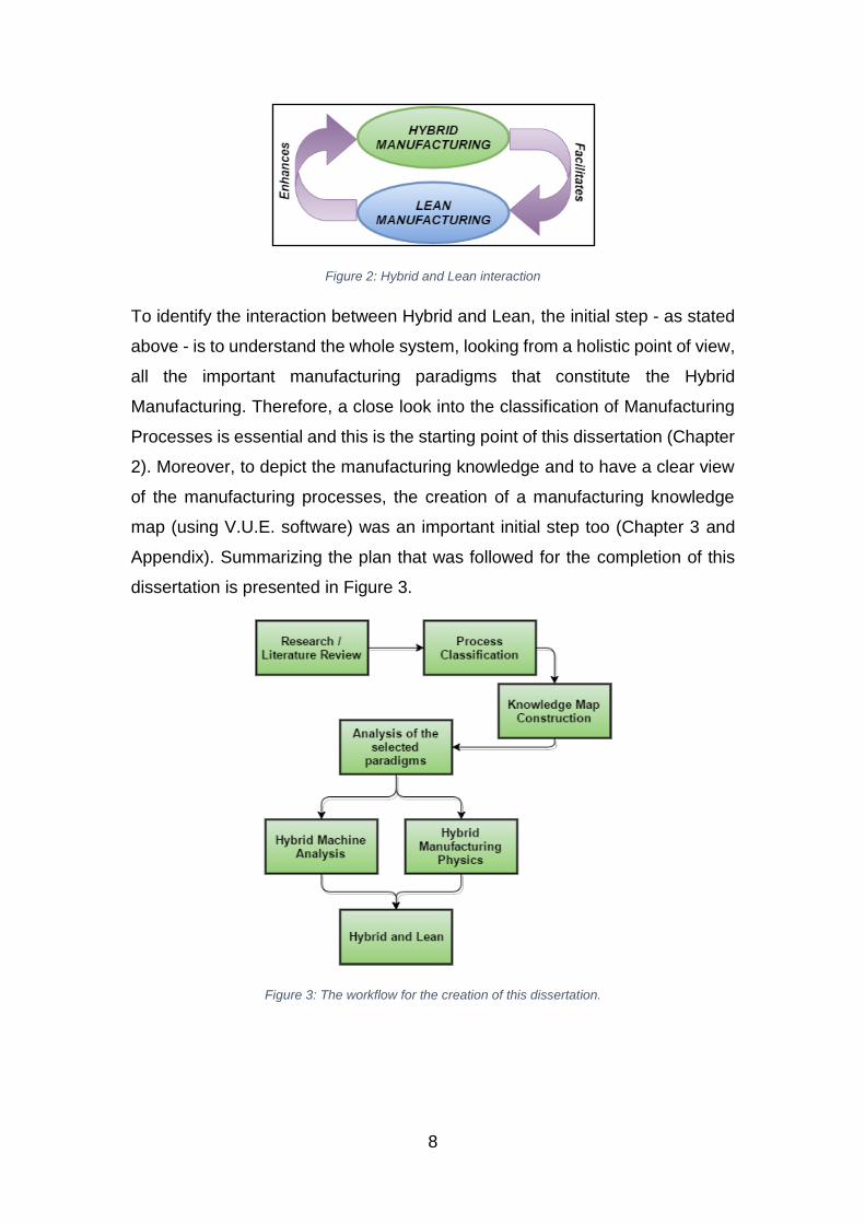
To identify the interaction between Hybrid and Lean, the initial step - as stated
above - is to understand the whole system, looking from a holistic point of view,
all the important manufacturing paradigms that constitute the Hybrid
Manufacturing. Therefore, a close look into the classification of Manufacturing
Processes is essential and this is the starting point of this dissertation (Chapter
2). Moreover, to depict the manufacturing knowledge and to have a clear view
of the manufacturing processes, the creation of a manufacturing knowledge
map (using V.U.E. software) was an important initial step too (Chapter 3 and
Appendix). Summarizing the plan that was followed for the completion of this
dissertation is presented in Figure 3.
Figure 3: The workflow for the creation of this dissertation.
9
2. Classification of Manufacturing Processes
This section presents the available process classifications in the literature,
following by a specific classification, which will be the basis of this dissertation.
2.1 Various process classifications in the literature
Many researchers have tried to classify manufacturing processes. Each
researcher tries to create the appropriate categorization to suite his/her
particular interests, audience and motivation. Swift and Booker [5] divide the
manufacturing processes into four major categories: Casting, Cutting, Forming
and Fabrication. This classification is design focused, providing the
characteristics of each process, as a strong base for promoting new design
ideas. Kalpakjian and Schmid [6] classify the processing methods of materials
into Casting, Forming/shaping, Machining, Joining, Micro/Nano Manufacturing
and Finishing. Groover [7] categorizes the manufacturing processes into two
broad categories: Processing operations and Assembly operations. The
Processing operations are those which change the shape, properties or/and the
appearance of the material. The Assembly operations, on the other hand,
create new entities by joining separate parts of materials together. Nassehi et
al. [8] divide the manufacturing processes into five different technologies:
Joining, Dividing, Subtractive, Transformative and Additive technology. This
classification strategy is appropriate for the identification and adding of new
technologies and it splits the processes according to their technological
capabilities. Although the above process classifications can provide a very good
base for further analysis and investigation, in this dissertation, there is a need
for a more holistic approach on process categorization.
2.2 Leo Alting’s classification of Manufacturing Processes
The selected classification of Leo Alting [9] divides the manufacturing
processes, as material flows, into three types: Mass Conserving, Mass
Reducing, and Assembly/Joining. This categorization facilitates the broad
and objective view of manufacturing processes that this dissertation needs to
follow.
10
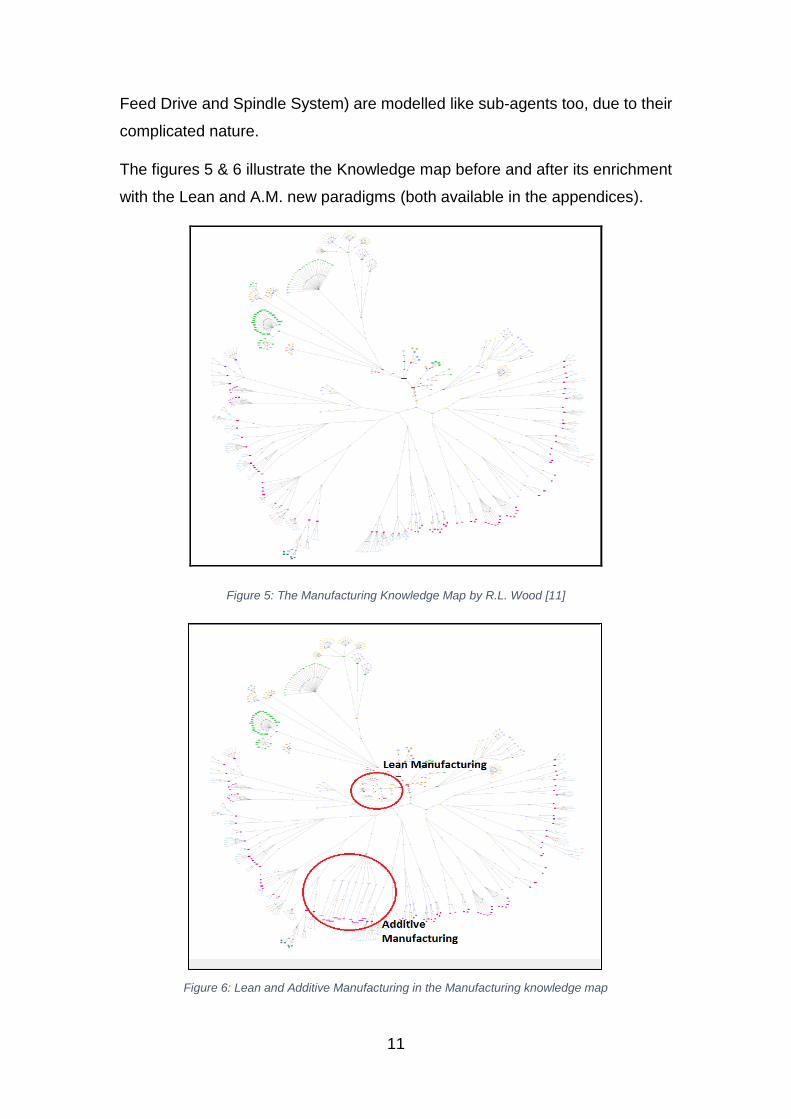
3. Modelling Method and Knowledge Mapping
Several studies are conducted to find ways to depict knowledge using a
structured visual approach, as well as, methods for Knowledge map building.
In the MMP105 module [10] of M.Sc. in Advanced Manufacturing Engineering
and Management in Loughborough University, a Manufacturing Knowledge
Map was introduced (Figure 5). This Knowledge Map – which is constructed
using “V.U.E.” Software – is used to enhance the understanding of
manufacturing. It contains various manufacturing paradigms, taxonomies and
process attributes. Although, it is at its initial stage, and it is considered as
incomplete, it provides a strong base for future enrichments of new entrant
technologies/paradigms. The existing knowledge map, which follows the
classification of Leo Alting, is created by R.L. Wood [11], lecturer and director
of the MSc in Advanced Manufacturing Engineering and Management
(Loughborough University). Although the paradigms of Computer Numerical
Control and Subtractive Manufacturing (Mass Reducing) were already existed,
the knowledge map is enriched by the new paradigms of Additive
Manufacturing (A.M.) and Lean Manufacturing (Figure 6). Additive
Manufacturing is considered as part of Mass Conserving processes, because
there is not mass reduction or assembly/joining. From a material point of view
is the melting and deposition/solidification of the same volume of material. Lean
is classified as Process Improvement, in the same group with Six Sigma,
T.Q.M., etc.
Apart from the Knowledge mapping, each sub-system of the Hybrid Machine is
considered as an agent that does three main actions: Receive, Decide, and Act.
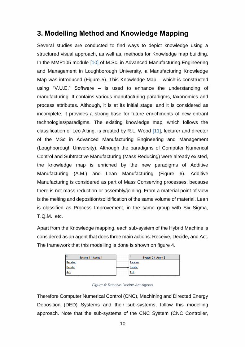
The framework that this modelling is done is shown on figure 4.
Figure 4: Receive-Decide-Act Agents
Therefore Computer Numerical Control (CNC), Machining and Directed Energy
Deposition (DED) Systems and their sub-systems, follow this modelling
approach. Note that the sub-systems of the CNC System (CNC Controller,
11
Feed Drive and Spindle System) are modelled like sub-agents too, due to their
complicated nature.
The figures 5 & 6 illustrate the Knowledge map before and after its enrichment
with the Lean and A.M. new paradigms (both available in the appendices).
Figure 5: The Manufacturing Knowledge Map by R.L. Wood [11]
Figure 6: Lean and Additive Manufacturing in the Manufacturing knowledge map
12
4. Review of selected paradigms
4.1 Computer Numerical Control
To define the paradigm of Computer Numerical Control (C.N.C.), the first step
is to take a look at the history and development of the machines tools.
Before 1950s all the machine tools were operated manually (Conventional
Machine Tools). In conventional machines the operator (the machinist) is the
most critical “part of the system”. He makes all the decisions, while manually
moves each axis to the desired position. The position feedback, as well as
loadings and torques, lie in the observation of the operator. In 1952, the first
Numerical Control machine was introduced in Massachusetts Institute of
Technology. Numerical Control (N.C.) is the system that controls the machine
tool using numerical data, which describes the functions of the machine. NC
machine tools were the intermediate stage between conventional and CNC
machine tools. In the mid-1960s were the first mini-computers were introduced,
the Computer Numerical Controlled machine tools were installed, providing
numerous advantages, mainly due to their control system. The control system
of a CNC machine, includes a computer, and this is the main difference
between NC and CNC [12].
The advances in CNC sector continue and there is a significant interest from
both academia and industry. Specifically, the advantages in CNC machining
technologies, are numerous. Li et al. provides a good overview of recent
advances in C.N.C. machining technologies and systems [13]. The combination
of embedded control technology with network technology in CNC systems is an
example of the intention of the global manufacturing for high performance CNC
systems [14]. Furthermore, advances concerning the CNC machine tools
structure (machine design) can be found in the literature, due to the fact that
the CNC machine structure is quite complex and many factors should be
considered concerning the its stiffness, robustness, mass, etc. [15].
In Chapter 6.2, the basic structure of a CNC System is explained and
decomposed into its critical sub-systems.
13
4.2 Subtractive Manufacturing
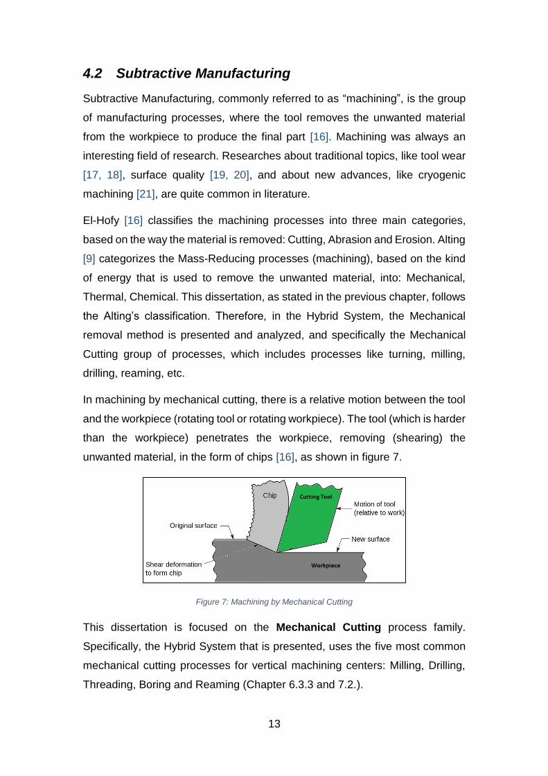
Subtractive Manufacturing, commonly referred to as “machining”, is the group
of manufacturing processes, where the tool removes the unwanted material
from the workpiece to produce the final part [16]. Machining was always an
interesting field of research. Researches about traditional topics, like tool wear
[17, 18], surface quality [19, 20], and about new advances, like cryogenic
machining [21], are quite common in literature.
El-Hofy [16] classifies the machining processes into three main categories,
based on the way the material is removed: Cutting, Abrasion and Erosion. Alting
[9] categorizes the Mass-Reducing processes (machining), based on the kind
of energy that is used to remove the unwanted material, into: Mechanical,
Thermal, Chemical. This dissertation, as stated in the previous chapter, follows
the Alting’s classification. Therefore, in the Hybrid System, the Mechanical
removal method is presented and analyzed, and specifically the Mechanical
Cutting group of processes, which includes processes like turning, milling,
drilling, reaming, etc.
In machining by mechanical cutting, there is a relative motion between the tool
and the workpiece (rotating tool or rotating workpiece). The tool (which is harder
than the workpiece) penetrates the workpiece, removing (shearing) the
unwanted material, in the form of chips [16], as shown in figure 7.
Figure 7: Machining by Mechanical Cutting
This dissertation is focused on the Mechanical Cutting process family.
Specifically, the Hybrid System that is presented, uses the five most common
mechanical cutting processes for vertical machining centers: Milling, Drilling,
Threading, Boring and Reaming (Chapter 6.3.3 and 7.2.).
14
4.3 Additive Manufacturing
Additive Manufacturing (AM) is a range of manufacturing processes that create
parts directly from Computer Aided Design (C.A.D.) data, in a layer-by-layer
method. This range of technologies were initially developed for prototyping [22,
23]. However, in 21st century there is an interest to be used for other purposes,
too, including end-to-end parts [22]. Both industry and academia show a
particular interest in this technology and numerous reviews have been
performed [22, 7, 24-27]. In 2010, the American Society for Testing & Materials
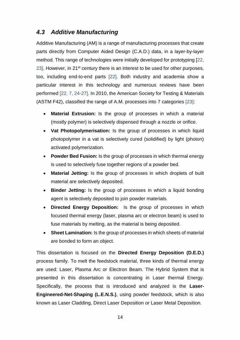
(ASTM F42), classified the range of A.M. processes into 7 categories [23]:
Material Extrusion: Is the group of processes in which a material
(mostly polymer) is selectively dispensed through a nozzle or orifice.
Vat Photopolymerisation: Is the group of processes in which liquid
photopolymer in a vat is selectively cured (solidified) by light (photon)
activated polymerization.
Powder Bed Fusion: Is the group of processes in which thermal energy
is used to selectively fuse together regions of a powder bed.
Material Jetting: Is the group of processes in which droplets of built
material are selectively deposited.
Binder Jetting: Is the group of processes in which a liquid bonding
agent is selectively deposited to join powder materials.
Directed Energy Deposition: Is the group of processes in which
focused thermal energy (laser, plasma arc or electron beam) is used to
fuse materials by melting, as the material is being deposited.
Sheet Lamination: Is the group of processes in which sheets of material
are bonded to form an object.
This dissertation is focused on the Directed Energy Deposition (D.E.D.)
process family. To melt the feedstock material, three kinds of thermal energy
are used: Laser, Plasma Arc or Electron Beam. The Hybrid System that is
presented in this dissertation is concentrating in Laser thermal Energy.
Specifically, the process that is introduced and analyzed is the Laser-
Engineered-Net-Shaping (L.E.N.S.), using powder feedstock, which is also
known as Laser Cladding, Direct Laser Deposition or Laser Metal Deposition.
15
4.4 Lean Manufacturing
Lean Manufacturing is a manufacturing philosophy and a management practice
that contains an improvement toolset aiming to meet customer needs [28]. The
focus of Lean implementation is the Waste (Muda) minimization/elimination [28-
31]. Lean was, firstly, introduced and implemented in Japan, by the industrial
engineer Taiichi Ohno [32], with the name “Toyota Production System” (or
T.P.S.). Later, Womack et al. [31], through on-side observation of various
industries, analyzed the T.P.S. and provided the principles of Lean Production.
Their classic book “The Machine that Changed the World”, in 1990, was the
first study that introduced the term “Lean Manufacturing” and it predicted that
Lean will have a big impact in global manufacturing. From 1990’s, Lean
Manufacturing started to evolve through years and it is still evolving [33]. Many
researchers tried to identify the key elements of Lean Manufacturing, creating
a classification scheme for various Lean tools. Shah and Ward [34] classified
the lean tools into four categories: Just in time, Total Productive Maintenance,
Total Quality Management and Human Resource Management. The
categorization of Moyano-Fuentes and Sacristan-Diaz [35] consists of four
main groups, too, however quite different (shop floor, value chain, work
organization, and impact of geographical context). Papadopoulou and
Ozbayrak [36] categorized the lean tools into 6 main categories: shopfloor
management, production planning, process oriented, scheduling/control, lean
implementation, management of the workforce, and management of the Supply
Chain. Feld [3] describes Lean manufacturing from a holistic point of view. He
defines Lean as a set of five interconnected key elements: Manufacturing Flow,
Organization, Process Control, Metrics and Logistics. Each of these
interconnected elements contains tools and techniques that can be
implemented to achieve Lean in the manufacturing environment. This
dissertation follows Feld’s classification of Lean principles, due to the fact that
it is the most appropriate for categorizing the vague terms of different Lean
tools. The Lean Manufacturing paradigm of the Manufacturing Knowledge Map
is constructed with the aid of these five basic Lean Elements. Finally,
Marchwinski and Shook [4] provide a practical guide, describing numerous
terms of Lean manufacturing that every Lean practitioner should be aware of.
16
5. Hybrid Manufacturing
5.1 Introduction
As mention above, Hybrid Manufacturing is the combination of different
manufacturing processes. As Zhu et al. [1] mention, the International Academy
for Production Engineering (CIRP) has suggested three definitions for
describing the new paradigm. According to CIRP Hybrid is:
1. “An integrated application or combination of different physical active
principles” (Definition of the process).
2. “An integrated combination of usually separated performed process steps”
(Definition of the process).
3. “Integrated machines, so called hybrid machines that can perform different
processes at one place” (Definition of the respective machines).
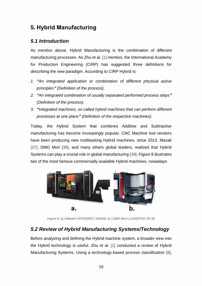
Today, the Hybrid System that combines Additive and Subtractive
manufacturing has become increasingly popular. CNC Machine tool vendors
have been producing new multitasking Hybrid machines, since 2013. Mazak
[37], DMG Mori [38], and many others global leaders, realized that Hybrid
Systems can play a crucial role in global manufacturing [39]. Figure 8 illustrates
two of the most famous commercially available Hybrid machines, nowadays.
Figure 8: (a.) Mazak’s INTEGREX i-400AM, (b.) DMG Mori’s LASERTEC 65 3D
5.2 Review of Hybrid Manufacturing Systems/Technology
Before analyzing and defining the Hybrid machine system, a broader view into
the Hybrid technology is useful. Zhu et al. [1] conducted a review of Hybrid
Manufacturing Systems. Using a technology-based process classification [8],

17
they classified hybrid manufacturing processes into seven Hybrid categories:
Subtractive, Transformative, Additive, Additive-Subtractive, Joining-
Subtractive, Additive-Transformative and Subtractive-Transformative. The
research provides a broad view of Hybrid Systems and a good understanding
of the Hybrid Manufacturing Processes reported during the last decades.
Lauwers et al. [40] classify the Hybrid processes performed in one machine,
into assisted processes and mixed processes. They focus on the benefits of
various kinds of Hybrid processes, stating that the hybrid process has many
more advantages than the advantages of the single processes. Lorenz et al.
[39] conducted a more specific review of Hybrid Manufacturing. In their paper,
they present the history of the Hybrid Manufacturing development, focusing
only on the combination of Directed Energy Deposition (Additive
Manufacturing) and CNC Machining. Commercially available Hybrid Systems
are presented, as well as the challenges of this new technology. Nowotny et al.
[41] describe the laser integration into machine tools for repairing or direct
manufacturing, with good accuracy and lead times. The same point of view
follow Jones et al. [42] describing the “RECLAIM project”, where Additive,
Subtractive and Inspection operations are performed by one machine and one
integrated software, to enhance flexibility in repairing/remanufacturing of
turbine blades.

18
6. Hybrid Machine Modelling and Analysis
6.1 Overview
The Hybrid Machine is a complex system. The decomposition of this system is
essential in order to understand its basic principles. Figure 9 illustrates a
diagram that constitutes the basic pylon of this research.
Figure 9: The Hybrid System decomposition.
6.2 Computer Numerical Control System
Introduction
The Computer Numerical Control System is the core system of the Hybrid
Machine. It is the common platform, where Machining and D.E.D. systems are
integrated and work simultaneously. The C.N.C. system can be decomposed
into three main systems: C.N.C. Controller (Chapter 6.2.1), Feed Drive
(Chapter 6.2.2) and Spindle Drive (Chapter 6.2.3).
6.2.1 CNC Controller
The following diagram (fig. 10) illustrates the main parts of CNC Controller and
their relation.
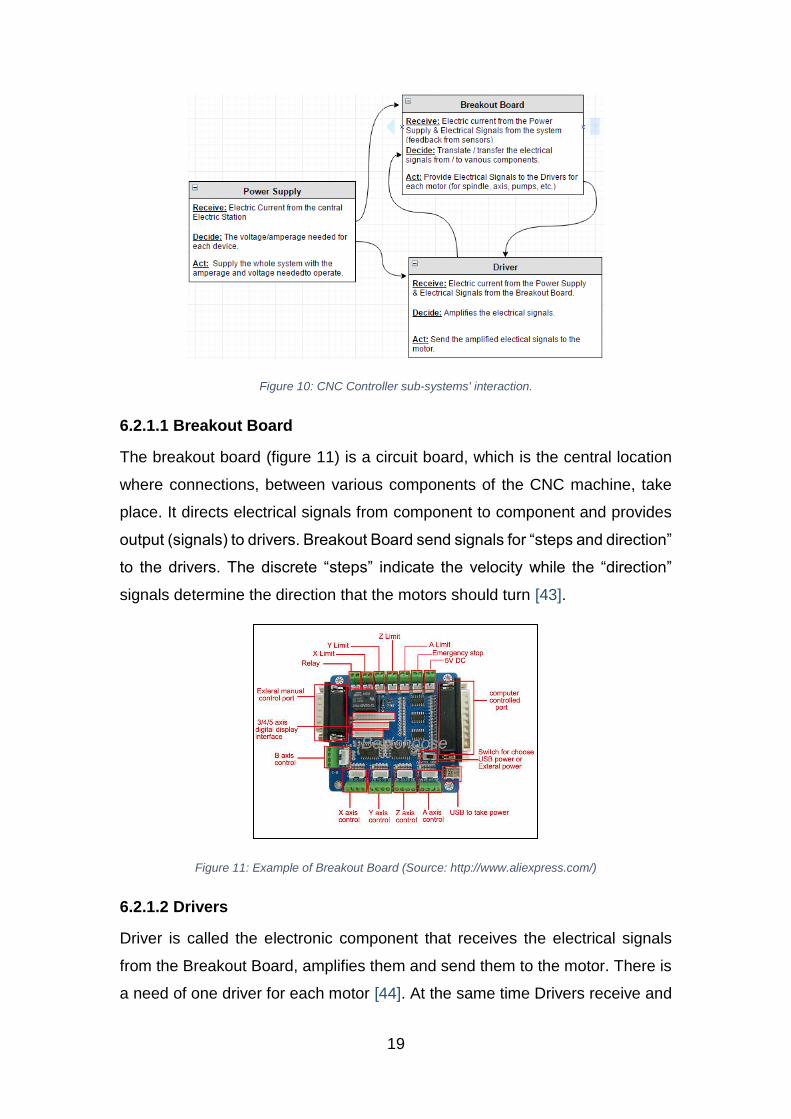
19
Figure 10: CNC Controller sub-systems' interaction.
6.2.1.1 Breakout Board
The breakout board (figure 11) is a circuit board, which is the central location
where connections, between various components of the CNC machine, take
place. It directs electrical signals from component to component and provides
output (signals) to drivers. Breakout Board send signals for “steps and direction”
to the drivers. The discrete “steps” indicate the velocity while the “direction”
signals determine the direction that the motors should turn [43].
Figure 11: Example of Breakout Board (Source: http://www.aliexpress.com/)
6.2.1.2 Drivers
Driver is called the electronic component that receives the electrical signals
from the Breakout Board, amplifies them and send them to the motor. There is
a need of one driver for each motor [44]. At the same time Drivers receive and

20
analyze signals from various sensors. There are spindle drivers/amplifiers and
servo drivers/amplifiers in the CNC system, as well as drivers for pumps and
powder feeders. Each driver is attached on the breakout board [43]. For
instance the driver for X-Axis is attached in the Breakout Board at the “X-Control
Axis” position (figures 11 and 12).
Figure 12: Digital CNC Driver Board (Source: http://www.themakersguide.com/)
6.2.1.3 Power Supply
The power supply (figure 13) provides to the whole system the amperage and
voltage needed to operate. The power supply requirements depend, mainly, on
the number and the type of motors, as well as their voltage and amperage
requirements [43].
Figure 13: Example of 320V Power Supply for Haas Inc. CNC (Source: www.galco.com)
6.2.2 Feed Drive System
The following diagram (fig. 14) illustrates the main parts of the Feed Drive
System and their relation.
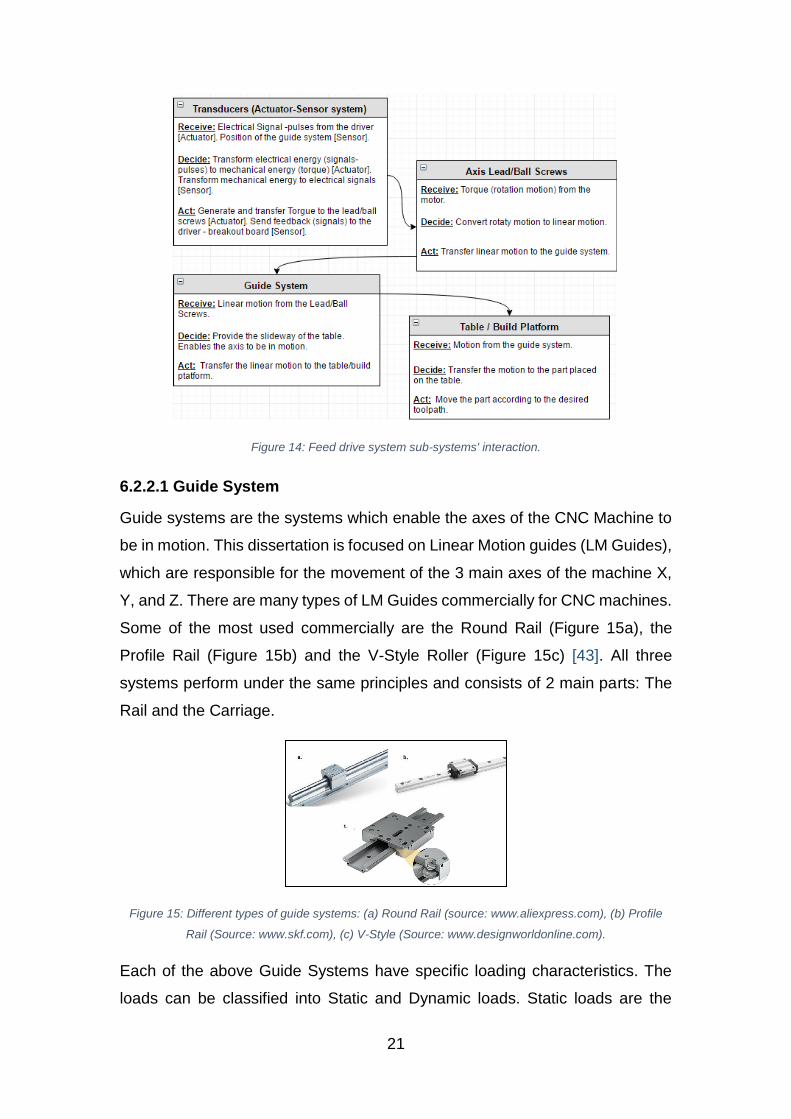
21
Figure 14: Feed drive system sub-systems' interaction.
6.2.2.1 Guide System
Guide systems are the systems which enable the axes of the CNC Machine to
be in motion. This dissertation is focused on Linear Motion guides (LM Guides),
which are responsible for the movement of the 3 main axes of the machine X,
Y, and Z. There are many types of LM Guides commercially for CNC machines.
Some of the most used commercially are the Round Rail (Figure 15a), the
Profile Rail (Figure 15b) and the V-Style Roller (Figure 15c) [43]. All three
systems perform under the same principles and consists of 2 main parts: The
Rail and the Carriage.
Figure 15: Different types of guide systems: (a) Round Rail (source: www.aliexpress.com), (b) Profile
Rail (Source: www.skf.com), (c) V-Style (Source: www.designworldonline.com).
Each of the above Guide Systems have specific loading characteristics. The
loads can be classified into Static and Dynamic loads. Static loads are the
22
forces that are always present in the system. Dynamic loads are the forces that
are created when there is a change into the system [43].
The table/build platform, is attached to the guide system. Actually, it is an
extension of the guide system, where the part is located.
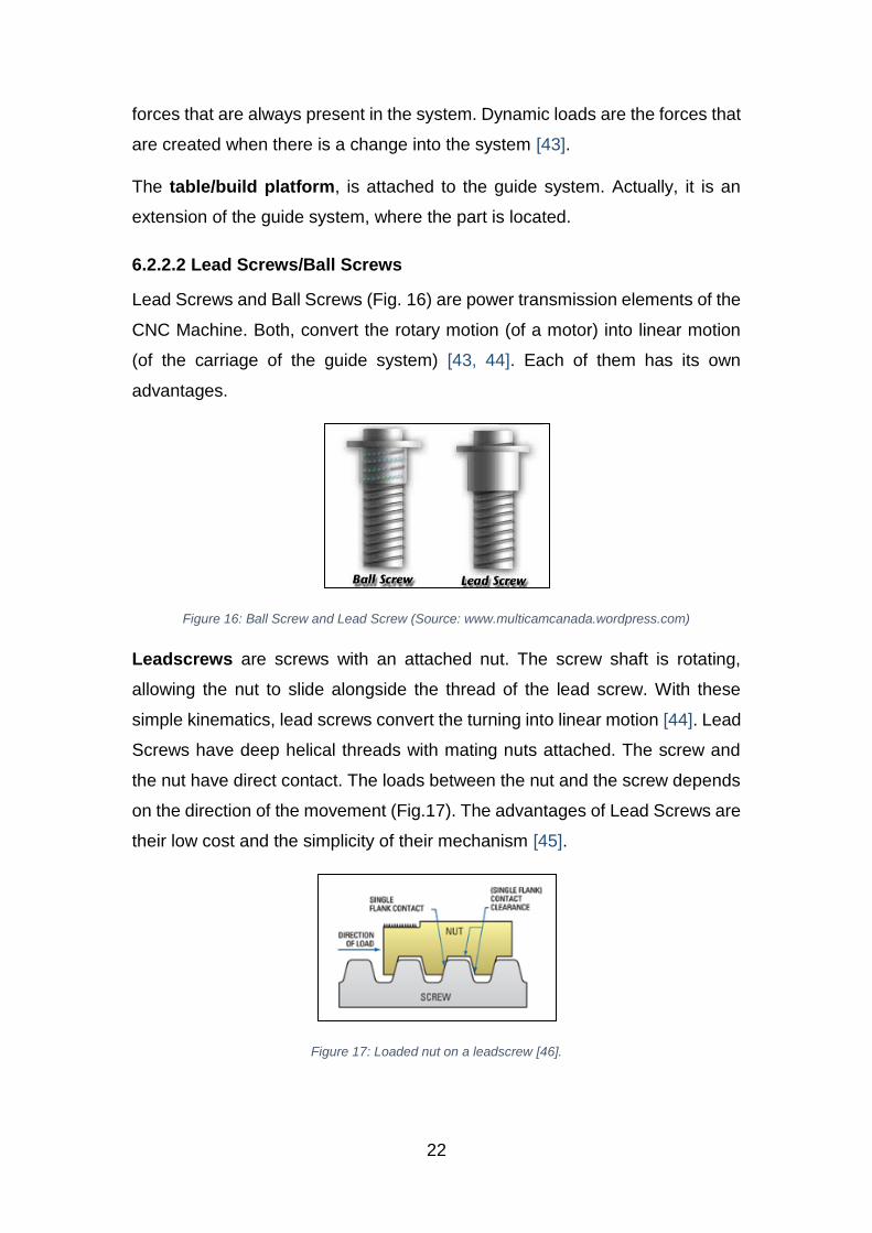
6.2.2.2 Lead Screws/Ball Screws
Lead Screws and Ball Screws (Fig. 16) are power transmission elements of the
CNC Machine. Both, convert the rotary motion (of a motor) into linear motion
(of the carriage of the guide system) [43, 44]. Each of them has its own
advantages.
Figure 16: Ball Screw and Lead Screw (Source: www.multicamcanada.wordpress.com)
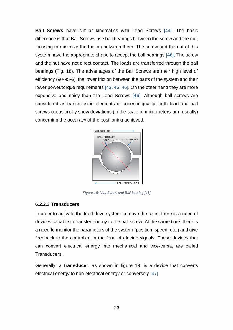
Leadscrews are screws with an attached nut. The screw shaft is rotating,
allowing the nut to slide alongside the thread of the lead screw. With these
simple kinematics, lead screws convert the turning into linear motion [44]. Lead
Screws have deep helical threads with mating nuts attached. The screw and
the nut have direct contact. The loads between the nut and the screw depends
on the direction of the movement (Fig.17). The advantages of Lead Screws are
their low cost and the simplicity of their mechanism [45].
Figure 17: Loaded nut on a leadscrew [46].
23
Ball Screws have similar kinematics with Lead Screws [44]. The basic
difference is that Ball Screws use ball bearings between the screw and the nut,
focusing to minimize the friction between them. The screw and the nut of this
system have the appropriate shape to accept the ball bearings [46]. The screw
and the nut have not direct contact. The loads are transferred through the ball
bearings (Fig. 18). The advantages of the Ball Screws are their high level of
efficiency (90-95%), the lower friction between the parts of the system and their
lower power/torque requirements [43, 45, 46]. On the other hand they are more
expensive and noisy than the Lead Screws [46]. Although ball screws are
considered as transmission elements of superior quality, both lead and ball
screws occasionally show deviations (in the scale of micrometers-μm- usually)
concerning the accuracy of the positioning achieved.
Figure 18: Nut, Screw and Ball bearing [46]
6.2.2.3 Transducers
In order to activate the feed drive system to move the axes, there is a need of
devices capable to transfer energy to the ball screw. At the same time, there is
a need to monitor the parameters of the system (position, speed, etc.) and give
feedback to the controller, in the form of electric signals. These devices that
can convert electrical energy into mechanical and vice-versa, are called
Transducers.
Generally, a transducer, as shown in figure 19, is a device that converts
electrical energy to non-electrical energy or conversely [47].
24
Figure 19: Generic functionality of a transducer
Transducers are divided into two categories [47]:
Actuators: An actuator is the type of transducer that inflict a condition
(e.g. Movement or control) of a system. Examples of actuators inside a
CNC machine are the motors (for both feed and spindle drive) and the
pumps.
Sensors: A sensor is the type of transducer that perceives the condition
of a system. Examples of sensors in a CNC machine are the encoders
(linear or rotary).
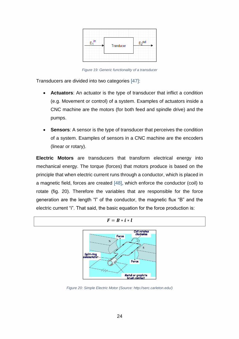
Electric Motors are transducers that transform electrical energy into
mechanical energy. The torque (forces) that motors produce is based on the
principle that when electric current runs through a conductor, which is placed in
a magnetic field, forces are created [48], which enforce the conductor (coil) to
rotate (fig. 20). Therefore the variables that are responsible for the force
generation are the length “l” of the conductor, the magnetic flux “B” and the
electric current “i”. That said, the basic equation for the force production is:
𝑭 = 𝑩 ∗ 𝒊 ∗ 𝒍
Figure 20: Simple Electric Motor (Source: http://serc.carleton.edu/)
25
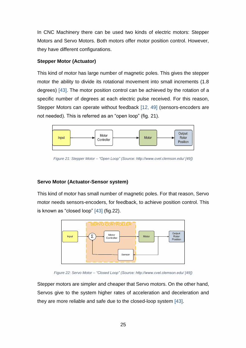
In CNC Machinery there can be used two kinds of electric motors: Stepper
Motors and Servo Motors. Both motors offer motor position control. However,
they have different configurations.
Stepper Motor (Actuator)
This kind of motor has large number of magnetic poles. This gives the stepper
motor the ability to divide its rotational movement into small increments (1.8
degrees) [43]. The motor position control can be achieved by the rotation of a
specific number of degrees at each electric pulse received. For this reason,
Stepper Motors can operate without feedback [12, 49] (sensors-encoders are
not needed). This is referred as an “open loop” (fig. 21).
Figure 21: Stepper Motor – “Open Loop” (Source: http://www.cvel.clemson.edu/ [49])
Servo Motor (Actuator-Sensor system)
This kind of motor has small number of magnetic poles. For that reason, Servo
motor needs sensors-encoders, for feedback, to achieve position control. This
is known as “closed loop” [43] (fig.22).
Figure 22: Servo Motor – “Closed Loop” (Source: http://www.cvel.clemson.edu/ [49])
Stepper motors are simpler and cheaper that Servo motors. On the other hand,
Servos give to the system higher rates of acceleration and deceleration and
they are more reliable and safe due to the closed-loop system [43].
26
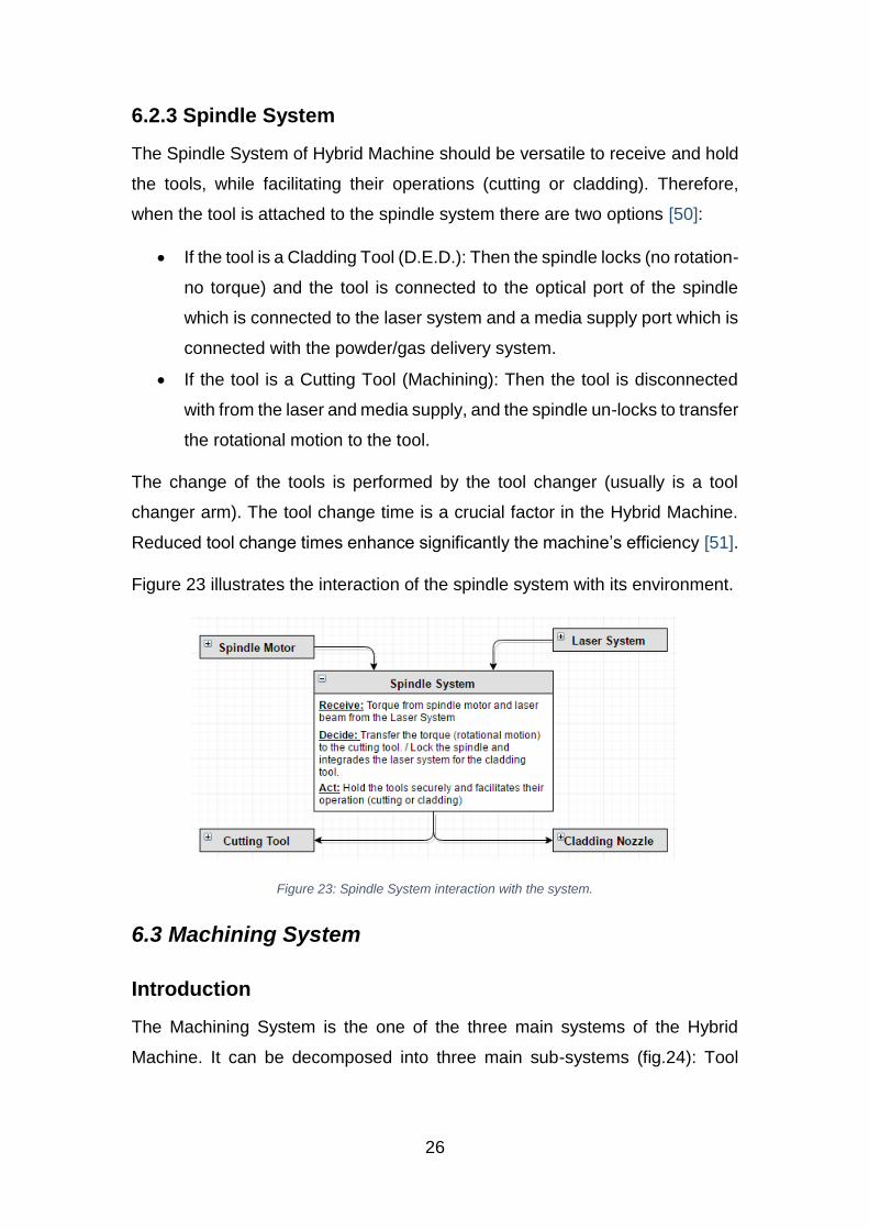
6.2.3 Spindle System
The Spindle System of Hybrid Machine should be versatile to receive and hold
the tools, while facilitating their operations (cutting or cladding). Therefore,
when the tool is attached to the spindle system there are two options [50]:
If the tool is a Cladding Tool (D.E.D.): Then the spindle locks (no rotation-
no torque) and the tool is connected to the optical port of the spindle
which is connected to the laser system and a media supply port which is
connected with the powder/gas delivery system.
If the tool is a Cutting Tool (Machining): Then the tool is disconnected
with from the laser and media supply, and the spindle un-locks to transfer
the rotational motion to the tool.
The change of the tools is performed by the tool changer (usually is a tool
changer arm). The tool change time is a crucial factor in the Hybrid Machine.
Reduced tool change times enhance significantly the machine’s efficiency [51].
Figure 23 illustrates the interaction of the spindle system with its environment.
Figure 23: Spindle System interaction with the system.
6.3 Machining System
Introduction
The Machining System is the one of the three main systems of the Hybrid
Machine. It can be decomposed into three main sub-systems (fig.24): Tool
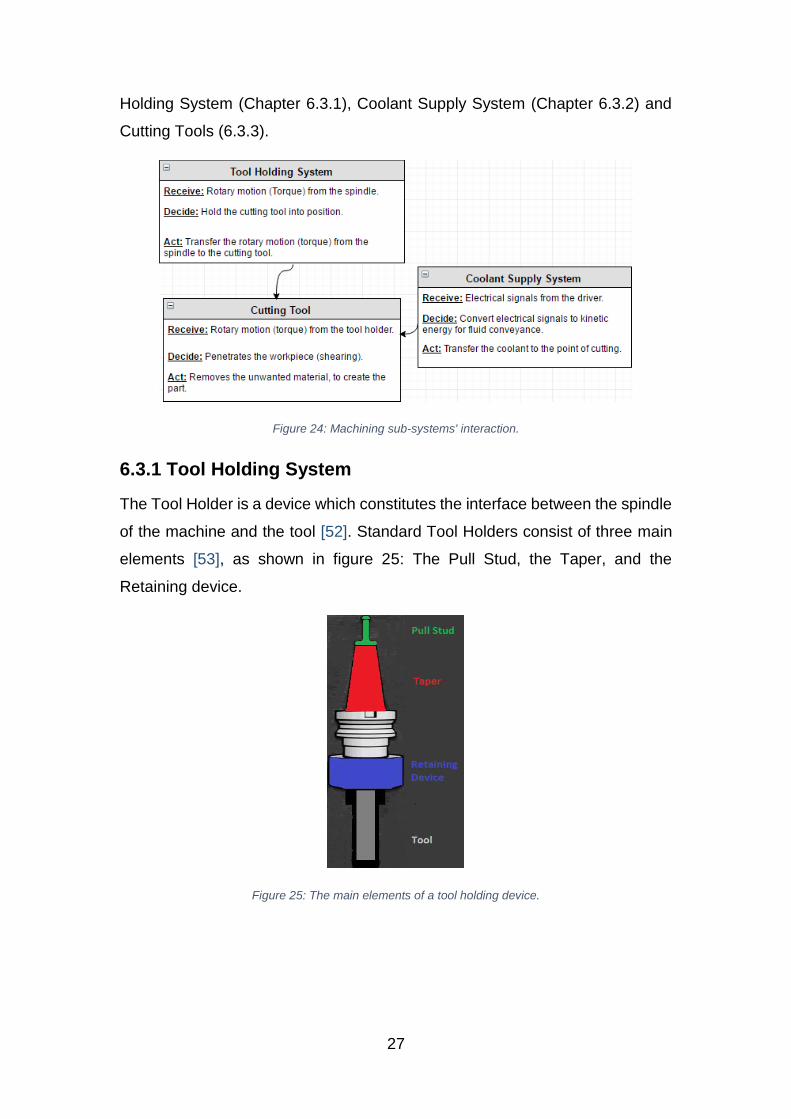
27
Holding System (Chapter 6.3.1), Coolant Supply System (Chapter 6.3.2) and
Cutting Tools (6.3.3).
Figure 24: Machining sub-systems' interaction.
6.3.1 Tool Holding System
The Tool Holder is a device which constitutes the interface between the spindle
of the machine and the tool [52]. Standard Tool Holders consist of three main
elements [53], as shown in figure 25: The Pull Stud, the Taper, and the
Retaining device.
Figure 25: The main elements of a tool holding device.
28
6.3.1.1 Pull Stud
The Pull Stud (also known as Retention Knob) is a critical component of the
tool holder (fig. 26). It is used to pull and hold the tool holder into the spindle
[54]. The pull stud is the part that connects the machine with the tool.
Figure 26: A Pull Stud (Source: [54])
Pull Studs are manufactured in a wide variety of difference types and sizes (fig.
27). The selection of the appropriate pull stud depends on the type/size of the
spindle and the type/size of the taper.
Figure 27: Various types of pull studs (Source: http://chopdaprecisiontools.com/)
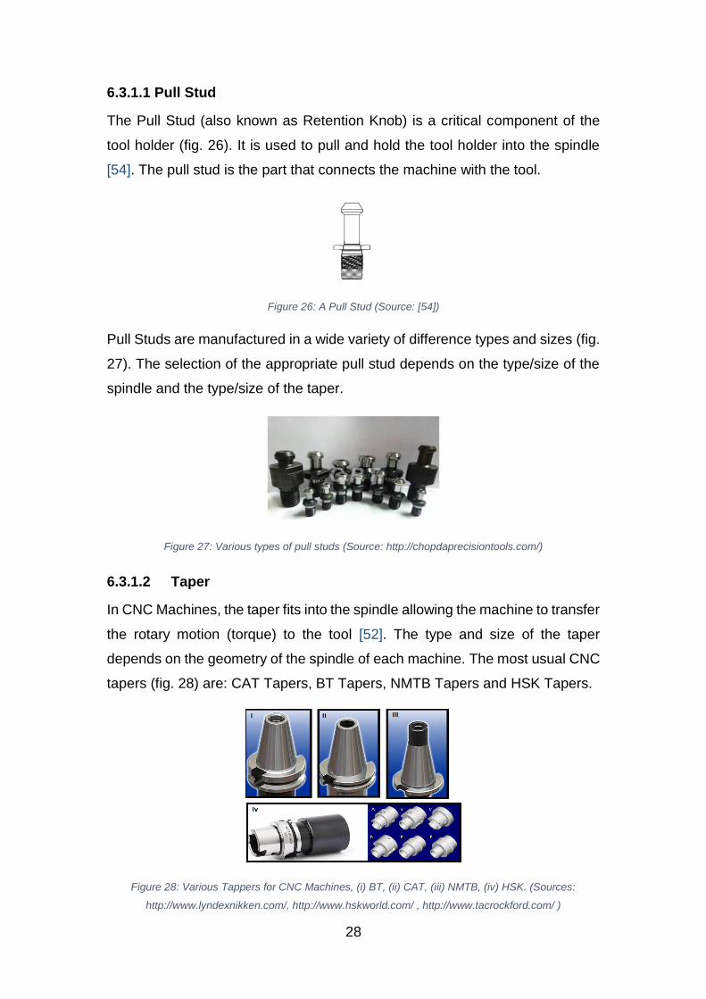
6.3.1.2 Taper
In CNC Machines, the taper fits into the spindle allowing the machine to transfer
the rotary motion (torque) to the tool [52]. The type and size of the taper
depends on the geometry of the spindle of each machine. The most usual CNC
tapers (fig. 28) are: CAT Tapers, BT Tapers, NMTB Tapers and HSK Tapers.
Figure 28: Various Tappers for CNC Machines, (i) BT, (ii) CAT, (iii) NMTB, (iv) HSK. (Sources:
http://www.lyndexnikken.com/, http://www.hskworld.com/ , http://www.tacrockford.com/ )
29
6.3.1.3 Retaining Device (Tool Clamping)
The retaining device is the part of the tool holding system that holds into position
the cutting tool, using various types of forces between the tool and the inner
walls of the tool holder. There is a variety of different techniques to clamp a
cutting tool. They can be summarized into three main categories: Radial
(external or internal), Axial (using pressure or tension), or the combination of
Radial and Axial [55]. More specifically, the types of retaining devices that are
used in industry are:
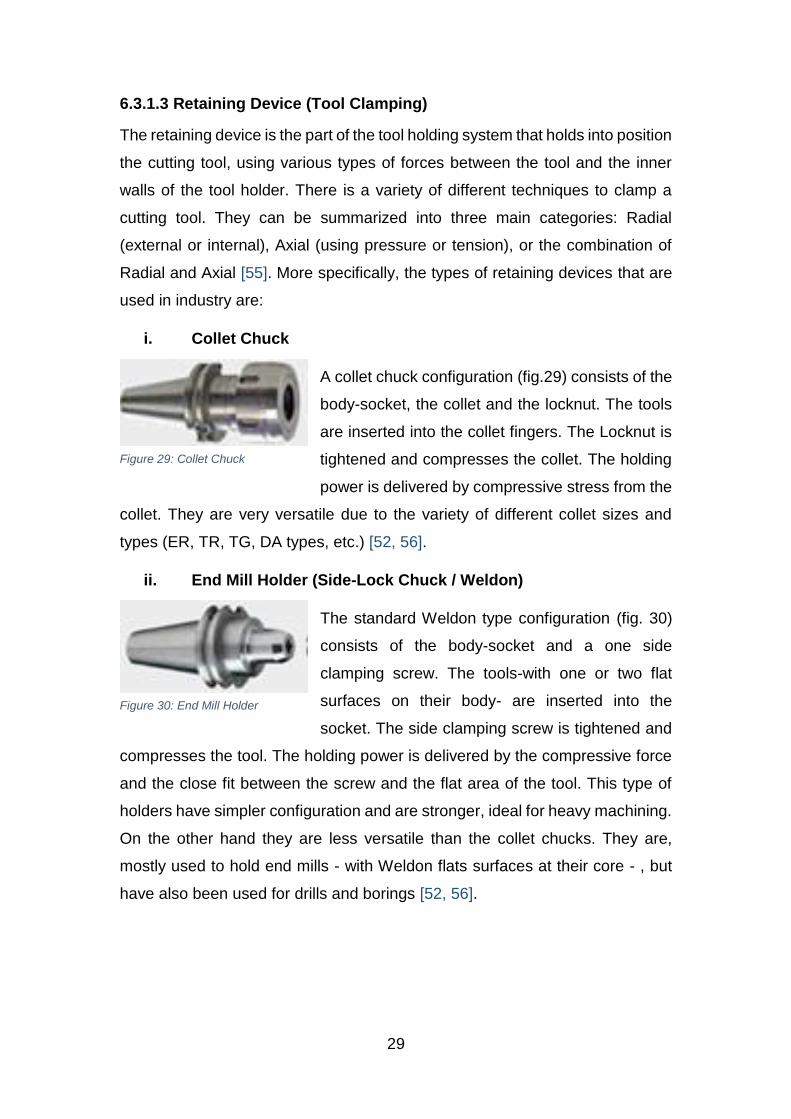
i. Collet Chuck
A collet chuck configuration (fig.29) consists of the
body-socket, the collet and the locknut. The tools
are inserted into the collet fingers. The Locknut is
tightened and compresses the collet. The holding
power is delivered by compressive stress from the
collet. They are very versatile due to the variety of different collet sizes and
types (ER, TR, TG, DA types, etc.) [52, 56].
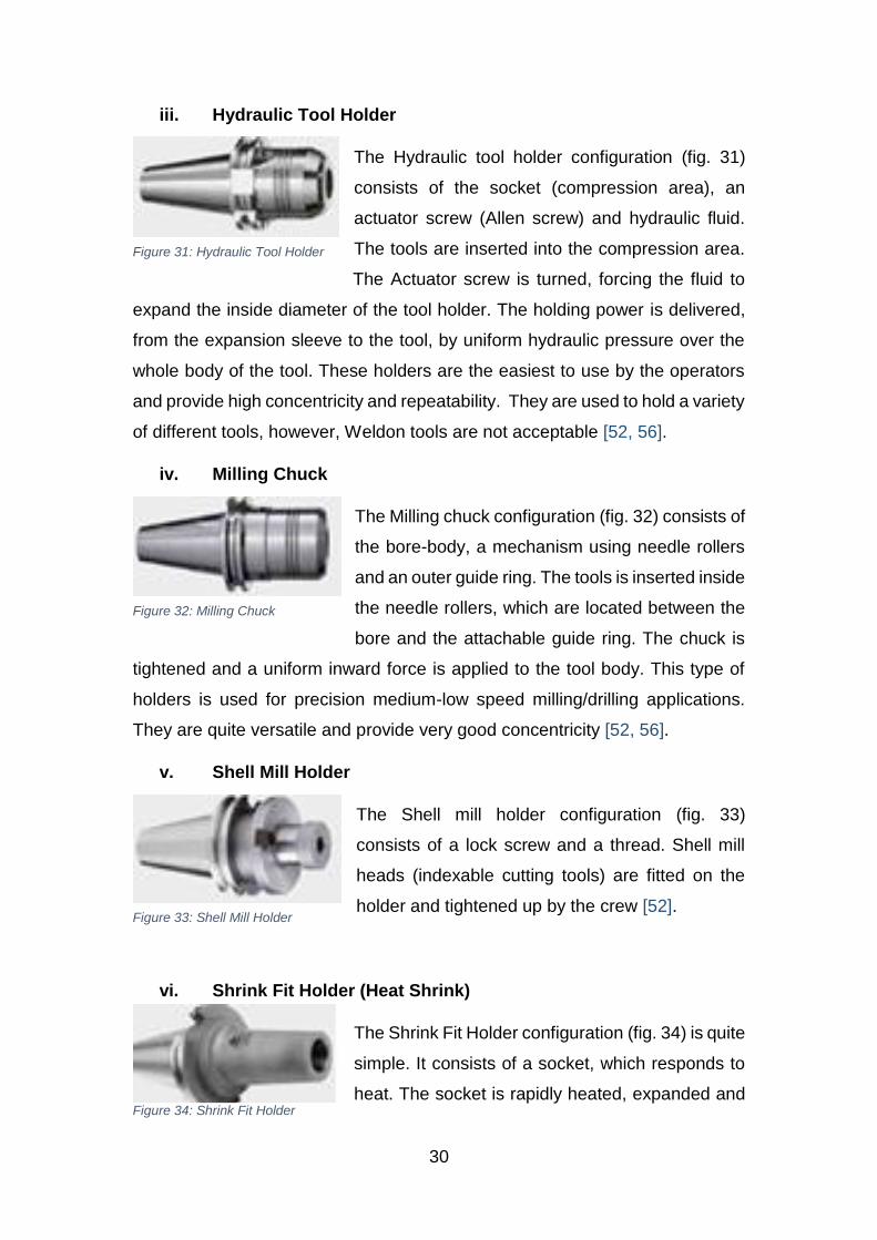
ii. End Mill Holder (Side-Lock Chuck / Weldon)
The standard Weldon type configuration (fig. 30)
consists of the body-socket and a one side
clamping screw. The tools-with one or two flat
surfaces on their body- are inserted into the
socket. The side clamping screw is tightened and
compresses the tool. The holding power is delivered by the compressive force
and the close fit between the screw and the flat area of the tool. This type of
holders have simpler configuration and are stronger, ideal for heavy machining.
On the other hand they are less versatile than the collet chucks. They are,
mostly used to hold end mills - with Weldon flats surfaces at their core - , but
have also been used for drills and borings [52, 56].
Figure 29: Collet Chuck
Figure 30: End Mill Holder
30
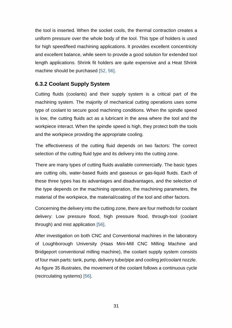
iii. Hydraulic Tool Holder
The Hydraulic tool holder configuration (fig. 31)
consists of the socket (compression area), an
actuator screw (Allen screw) and hydraulic fluid.
The tools are inserted into the compression area.
The Actuator screw is turned, forcing the fluid to
expand the inside diameter of the tool holder. The holding power is delivered,
from the expansion sleeve to the tool, by uniform hydraulic pressure over the
whole body of the tool. These holders are the easiest to use by the operators
and provide high concentricity and repeatability. They are used to hold a variety
of different tools, however, Weldon tools are not acceptable [52, 56].
iv. Milling Chuck
The Milling chuck configuration (fig. 32) consists of
the bore-body, a mechanism using needle rollers
and an outer guide ring. The tools is inserted inside
the needle rollers, which are located between the
bore and the attachable guide ring. The chuck is
tightened and a uniform inward force is applied to the tool body. This type of
holders is used for precision medium-low speed milling/drilling applications.
They are quite versatile and provide very good concentricity [52, 56].
v. Shell Mill Holder
The Shell mill holder configuration (fig. 33)
consists of a lock screw and a thread. Shell mill
heads (indexable cutting tools) are fitted on the
holder and tightened up by the crew [52].
vi. Shrink Fit Holder (Heat Shrink)
The Shrink Fit Holder configuration (fig. 34) is quite
simple. It consists of a socket, which responds to
heat. The socket is rapidly heated, expanded and
Figure 31: Hydraulic Tool Holder
Figure 32: Milling Chuck
Figure 33: Shell Mill Holder
Figure 34: Shrink Fit Holder
31
the tool is inserted. When the socket cools, the thermal contraction creates a
uniform pressure over the whole body of the tool. This type of holders is used
for high speed/feed machining applications. It provides excellent concentricity
and excellent balance, while seem to provide a good solution for extended tool
length applications. Shrink fit holders are quite expensive and a Heat Shrink
machine should be purchased [52, 56].
6.3.2 Coolant Supply System
Cutting fluids (coolants) and their supply system is a critical part of the
machining system. The majority of mechanical cutting operations uses some
type of coolant to secure good machining conditions. When the spindle speed
is low, the cutting fluids act as a lubricant in the area where the tool and the
workpiece interact. When the spindle speed is high, they protect both the tools
and the workpiece providing the appropriate cooling.
The effectiveness of the cutting fluid depends on two factors: The correct
selection of the cutting fluid type and its delivery into the cutting zone.
There are many types of cutting fluids available commercially. The basic types
are cutting oils, water-based fluids and gaseous or gas-liquid fluids. Each of
these three types has its advantages and disadvantages, and the selection of
the type depends on the machining operation, the machining parameters, the
material of the workpiece, the material/coating of the tool and other factors.
Concerning the delivery into the cutting zone, there are four methods for coolant
delivery: Low pressure flood, high pressure flood, through-tool (coolant
through) and mist application [56].
After investigation on both CNC and Conventional machines in the laboratory
of Loughborough University (Haas Mini-Mill CNC Milling Machine and
Bridgeport conventional milling machine), the coolant supply system consists
of four main parts: tank, pump, delivery tube/pipe and cooling jet/coolant nozzle.
As figure 35 illustrates, the movement of the coolant follows a continuous cycle
(recirculating systems) [56].
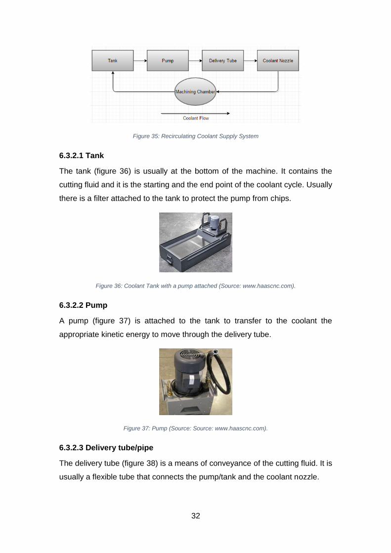
32
Figure 35: Recirculating Coolant Supply System
6.3.2.1 Tank
The tank (figure 36) is usually at the bottom of the machine. It contains the
cutting fluid and it is the starting and the end point of the coolant cycle. Usually
there is a filter attached to the tank to protect the pump from chips.
Figure 36: Coolant Tank with a pump attached (Source: www.haascnc.com).
6.3.2.2 Pump
A pump (figure 37) is attached to the tank to transfer to the coolant the
appropriate kinetic energy to move through the delivery tube.
Figure 37: Pump (Source: Source: www.haascnc.com).
6.3.2.3 Delivery tube/pipe
The delivery tube (figure 38) is a means of conveyance of the cutting fluid. It is
usually a flexible tube that connects the pump/tank and the coolant nozzle.
33
Figure 38: Coolant delivery tube (Source: www.aliexpress.com)
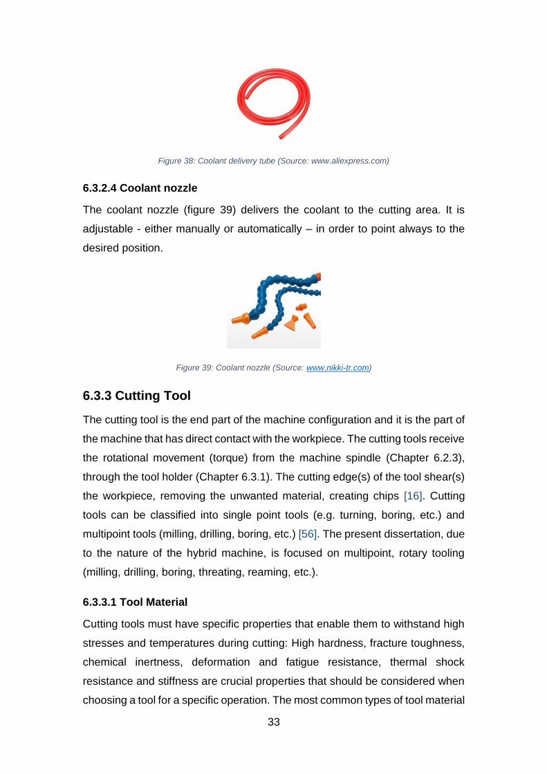
6.3.2.4 Coolant nozzle
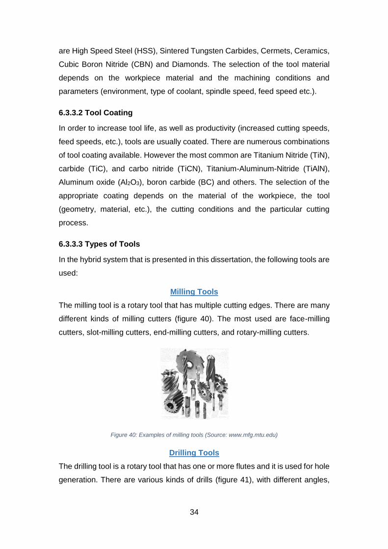
The coolant nozzle (figure 39) delivers the coolant to the cutting area. It is
adjustable - either manually or automatically – in order to point always to the
desired position.
Figure 39: Coolant nozzle (Source: www.nikki-tr.com)
6.3.3 Cutting Tool
The cutting tool is the end part of the machine configuration and it is the part of
the machine that has direct contact with the workpiece. The cutting tools receive
the rotational movement (torque) from the machine spindle (Chapter 6.2.3),
through the tool holder (Chapter 6.3.1). The cutting edge(s) of the tool shear(s)
the workpiece, removing the unwanted material, creating chips [16]. Cutting
tools can be classified into single point tools (e.g. turning, boring, etc.) and
multipoint tools (milling, drilling, boring, etc.) [56]. The present dissertation, due
to the nature of the hybrid machine, is focused on multipoint, rotary tooling
(milling, drilling, boring, threating, reaming, etc.).
6.3.3.1 Tool Material
Cutting tools must have specific properties that enable them to withstand high
stresses and temperatures during cutting: High hardness, fracture toughness,
chemical inertness, deformation and fatigue resistance, thermal shock
resistance and stiffness are crucial properties that should be considered when
choosing a tool for a specific operation. The most common types of tool material
34
are High Speed Steel (HSS), Sintered Tungsten Carbides, Cermets, Ceramics,
Cubic Boron Nitride (CBN) and Diamonds. The selection of the tool material
depends on the workpiece material and the machining conditions and
parameters (environment, type of coolant, spindle speed, feed speed etc.).
6.3.3.2 Tool Coating
In order to increase tool life, as well as productivity (increased cutting speeds,
feed speeds, etc.), tools are usually coated. There are numerous combinations
of tool coating available. However the most common are Titanium Nitride (TiN),
carbide (TiC), and carbo nitride (TiCN), Titanium-Aluminum-Nitride (TiAlN),
Aluminum oxide (Al2O3), boron carbide (BC) and others. The selection of the
appropriate coating depends on the material of the workpiece, the tool
(geometry, material, etc.), the cutting conditions and the particular cutting
process.
6.3.3.3 Types of Tools
In the hybrid system that is presented in this dissertation, the following tools are
used:
Milling Tools
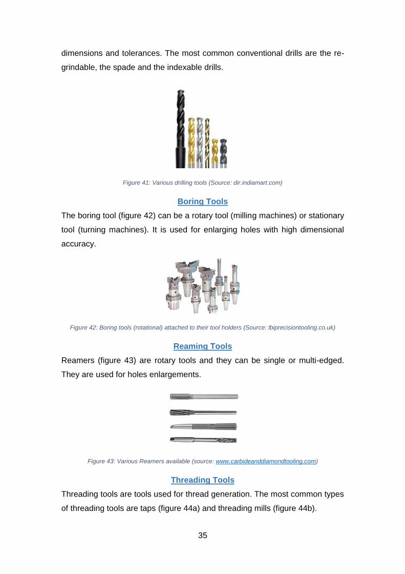
The milling tool is a rotary tool that has multiple cutting edges. There are many
different kinds of milling cutters (figure 40). The most used are face-milling
cutters, slot-milling cutters, end-milling cutters, and rotary-milling cutters.
Figure 40: Examples of milling tools (Source: www.mfg.mtu.edu)
Drilling Tools
The drilling tool is a rotary tool that has one or more flutes and it is used for hole
generation. There are various kinds of drills (figure 41), with different angles,
35
dimensions and tolerances. The most common conventional drills are the re-
grindable, the spade and the indexable drills.
Figure 41: Various drilling tools (Source: dir.indiamart.com)
Boring Tools
The boring tool (figure 42) can be a rotary tool (milling machines) or stationary
tool (turning machines). It is used for enlarging holes with high dimensional
accuracy.
Figure 42: Boring tools (rotational) attached to their tool holders (Source: lbiprecisiontooling.co.uk)
Reaming Tools
Reamers (figure 43) are rotary tools and they can be single or multi-edged.
They are used for holes enlargements.
Figure 43: Various Reamers available (source: www.carbideanddiamondtooling.com)
Threading Tools
Threading tools are tools used for thread generation. The most common types
of threading tools are taps (figure 44a) and threading mills (figure 44b).
36
Figure 44: (a) Taps (source: cutting-tools.com.au), (b) Thread mills (source: guhring.com)
The design of the above cutting tools are expressed by equations, which
describe their geometries, the contact angles, the entry angles and the
stepover. Stephenson and Agapiou [56] have conducted a complete review of
the equations needed to understand the physics behind each tool geometry.
6.4 Directed Energy Deposition System
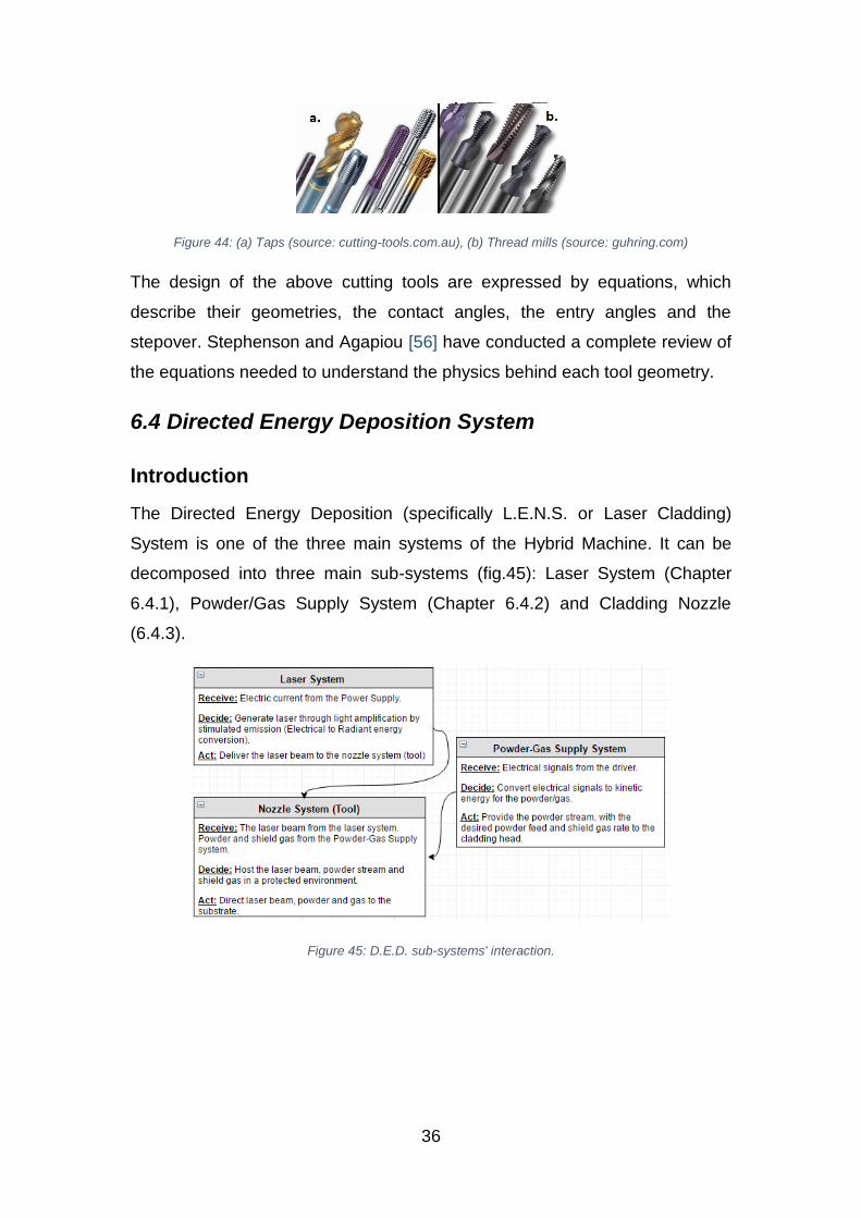
Introduction
The Directed Energy Deposition (specifically L.E.N.S. or Laser Cladding)
System is one of the three main systems of the Hybrid Machine. It can be
decomposed into three main sub-systems (fig.45): Laser System (Chapter
6.4.1), Powder/Gas Supply System (Chapter 6.4.2) and Cladding Nozzle
(6.4.3).
Figure 45: D.E.D. sub-systems' interaction.

37
6.4.1 Laser System
6.4.1.1 Underpinning physics of Laser Generation
Before the analysis of the laser system, it is useful to understand the basic
physics of the Laser Generation.
Laser is a form of electromagnetic radiation in/around the visible region of the
spectrum, as shown in figure 46.
Figure 46: Region of spectrum of Laser (Source: Loughborough University)
The word “laser” was introduced by Schawlow and Townes, and it is the
acronym for “Light Amplification by Stimulated Emission of Radiation” [57]. The
name indicates the basic principle on which Laser works: The stimulated
emission phenomenon discussed by Albert Einstein [58]. Laser differs from the
usual light having the following characteristics [59]: Monochromatic, coherent,
directional and focused.
In nature, atoms, inside an electromagnetic field, can exist in specified energy
states. Inside an atom electrons orbits occupy specific energy levels. If there
are two energy levels (E1<E2), a transition between E1 to E2 or E2 to E1 leads
the atom to absorb or emit a photon (with energy δΕ=hυ), respectively. The
basic equation of this transition is:
ℎ𝜐12 = |𝛦1 − 𝛦2|
Where: h is the Planck’s constant, υ12 is the frequency.
During the generation of a Laser beam, the following mechanisms take place
in a Laser System:
38
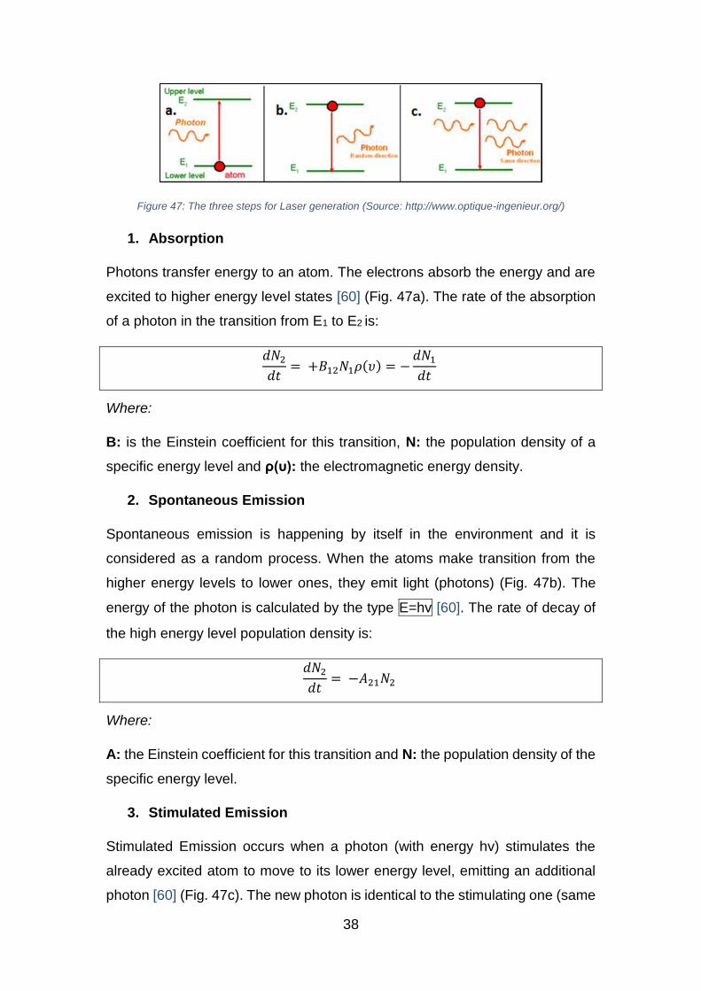
Figure 47: The three steps for Laser generation (Source: http://www.optique-ingenieur.org/)
1. Absorption
Photons transfer energy to an atom. The electrons absorb the energy and are
excited to higher energy level states [60] (Fig. 47a). The rate of the absorption
of a photon in the transition from E1 to E2 is:
𝑑𝑁2
𝑑𝑡= +𝐵12𝑁1𝜌(𝜐) = −
𝑑𝑁1
𝑑𝑡
Where:
B: is the Einstein coefficient for this transition, N: the population density of a
specific energy level and ρ(υ): the electromagnetic energy density.
2. Spontaneous Emission
Spontaneous emission is happening by itself in the environment and it is
considered as a random process. When the atoms make transition from the
higher energy levels to lower ones, they emit light (photons) (Fig. 47b). The
energy of the photon is calculated by the type E=hv [60]. The rate of decay of
the high energy level population density is:
𝑑𝑁2
𝑑𝑡= −𝐴21𝑁2
Where:
A: the Einstein coefficient for this transition and N: the population density of the
specific energy level.
3. Stimulated Emission
Stimulated Emission occurs when a photon (with energy hv) stimulates the
already excited atom to move to its lower energy level, emitting an additional
photon [60] (Fig. 47c). The new photon is identical to the stimulating one (same
39
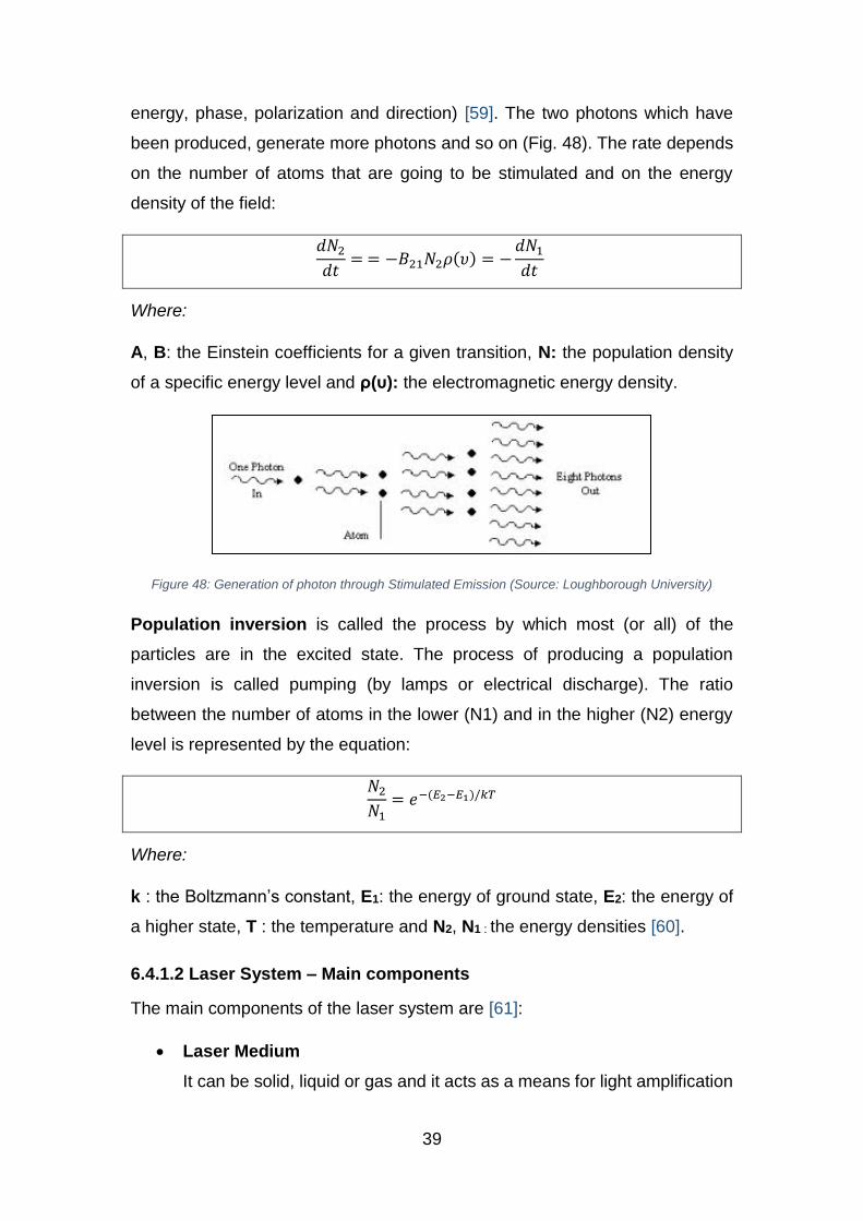
energy, phase, polarization and direction) [59]. The two photons which have
been produced, generate more photons and so on (Fig. 48). The rate depends
on the number of atoms that are going to be stimulated and on the energy
density of the field:
𝑑𝑁2
𝑑𝑡= = −𝐵21𝑁2𝜌(𝜐) = −
𝑑𝑁1
𝑑𝑡
Where:
A, B: the Einstein coefficients for a given transition, N: the population density
of a specific energy level and ρ(υ): the electromagnetic energy density.
Figure 48: Generation of photon through Stimulated Emission (Source: Loughborough University)
Population inversion is called the process by which most (or all) of the
particles are in the excited state. The process of producing a population
inversion is called pumping (by lamps or electrical discharge). The ratio
between the number of atoms in the lower (N1) and in the higher (N2) energy
level is represented by the equation:
𝑁2
𝑁1= 𝑒−(𝐸2−𝐸1)/𝑘𝑇
Where:
k : the Boltzmann’s constant, E1: the energy of ground state, E2: the energy of
a higher state, T : the temperature and N2, N1 : the energy densities [60].
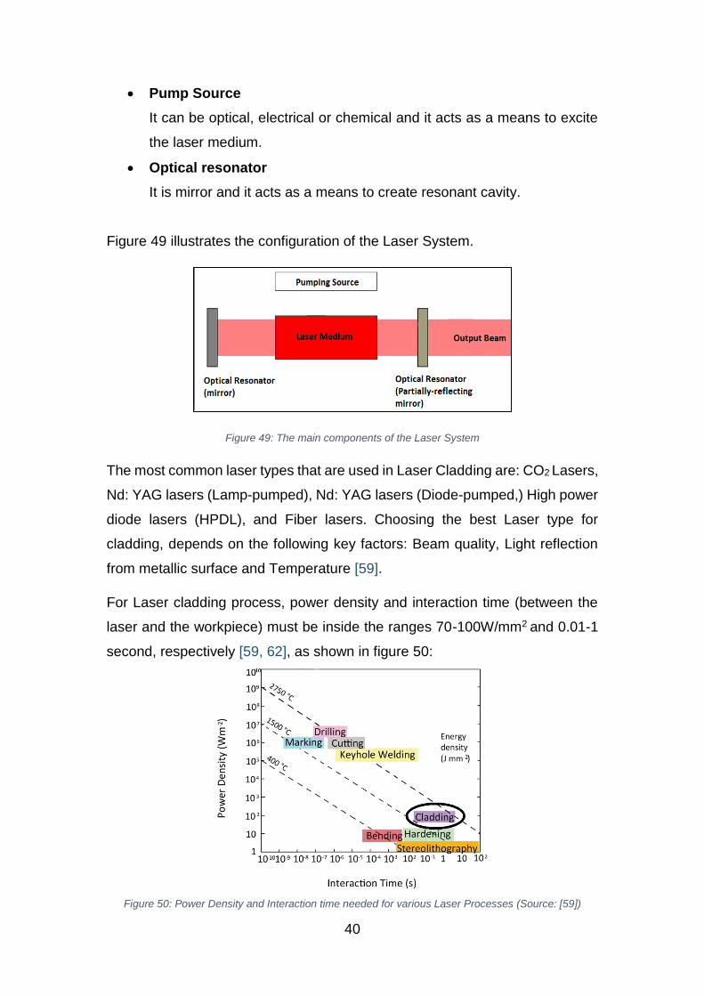
6.4.1.2 Laser System – Main components
The main components of the laser system are [61]:
Laser Medium
It can be solid, liquid or gas and it acts as a means for light amplification
40
Pump Source
It can be optical, electrical or chemical and it acts as a means to excite
the laser medium.
Optical resonator
It is mirror and it acts as a means to create resonant cavity.
Figure 49 illustrates the configuration of the Laser System.
Figure 49: The main components of the Laser System
The most common laser types that are used in Laser Cladding are: CO2 Lasers,
Nd: YAG lasers (Lamp-pumped), Nd: YAG lasers (Diode-pumped,) High power
diode lasers (HPDL), and Fiber lasers. Choosing the best Laser type for
cladding, depends on the following key factors: Beam quality, Light reflection
from metallic surface and Temperature [59].
For Laser cladding process, power density and interaction time (between the
laser and the workpiece) must be inside the ranges 70-100W/mm2 and 0.01-1
second, respectively [59, 62], as shown in figure 50:
Figure 50: Power Density and Interaction time needed for various Laser Processes (Source: [59])
41
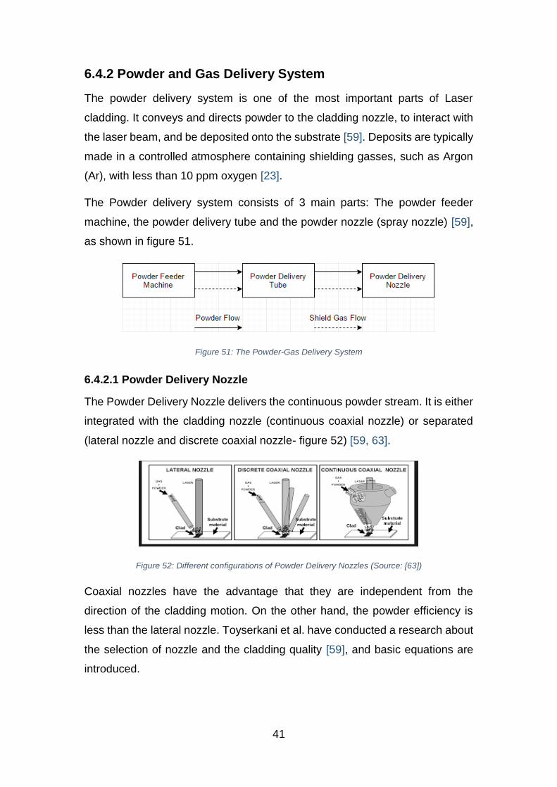
6.4.2 Powder and Gas Delivery System
The powder delivery system is one of the most important parts of Laser
cladding. It conveys and directs powder to the cladding nozzle, to interact with
the laser beam, and be deposited onto the substrate [59]. Deposits are typically
made in a controlled atmosphere containing shielding gasses, such as Argon
(Ar), with less than 10 ppm oxygen [23].
The Powder delivery system consists of 3 main parts: The powder feeder
machine, the powder delivery tube and the powder nozzle (spray nozzle) [59],
as shown in figure 51.
Figure 51: The Powder-Gas Delivery System
6.4.2.1 Powder Delivery Nozzle
The Powder Delivery Nozzle delivers the continuous powder stream. It is either
integrated with the cladding nozzle (continuous coaxial nozzle) or separated
(lateral nozzle and discrete coaxial nozzle- figure 52) [59, 63].
Figure 52: Different configurations of Powder Delivery Nozzles (Source: [63])
Coaxial nozzles have the advantage that they are independent from the
direction of the cladding motion. On the other hand, the powder efficiency is
less than the lateral nozzle. Toyserkani et al. have conducted a research about
the selection of nozzle and the cladding quality [59], and basic equations are
introduced.
42
6.4.2.2 Powder Delivery Tube
The Powder Delivery Tube is a means of conveyance for the powder stream. It
is usually a flexible tube that connects the powder nozzle with the powder
feeder.
6.4.2.3 Powder Feeder Machine
The Powder Feeder Machine provides the necessary powder feed and shield
gas rate to the cladding head. In the industry there are many types of powder
feeder machines, for various industrial applications. Based on their operation,
they can be classified into the following four categories: Gravity-based,
Mechanical wheel, Fluidized-bed and Vibrating.
All types of powder feeders need gas to facilitate the transportation of powder
particles to the final destination [59].
6.4.3 Cladding Nozzle System
In the particular Hybrid System, the cladding nozzle is the tool of the Directed
Energy Deposition System and it is integrated into a usual CNC tool holder (see
Chapter 6.3.1). The tool is changeable and it is stored into the tool magazine of
the machine [39]. This means that the spindle drive system (Chapter 6.2.3) can
change Machining and D.E.D. tools according to the desired operation,
automatically, which can be performed while the machine is running (internal
operation). The cladding nozzle of the Hybrid System needs to be coaxial.
Figure 53 illustrates the first commercially available changeable cladding
nozzle created by “Hybrid Manufacturing Technologies Ltd”.
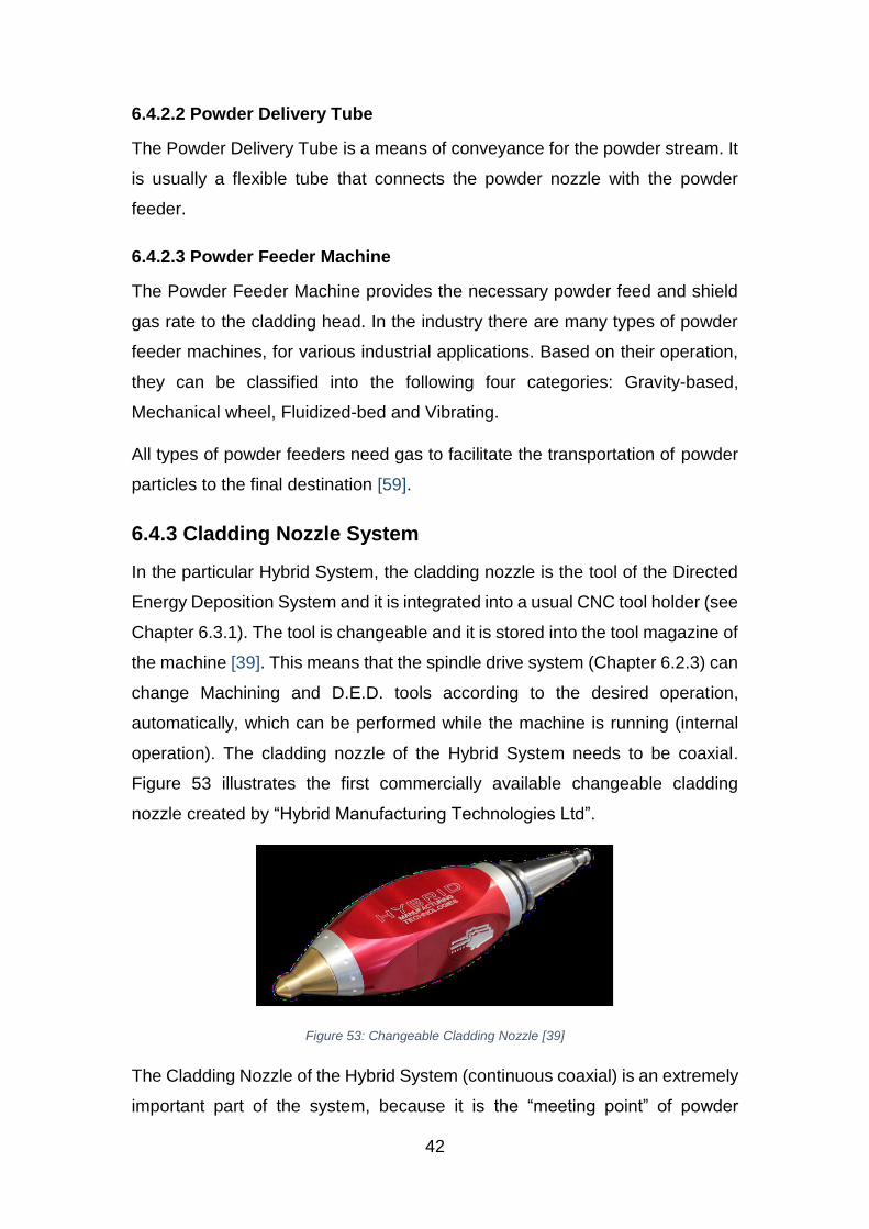
Figure 53: Changeable Cladding Nozzle [39]
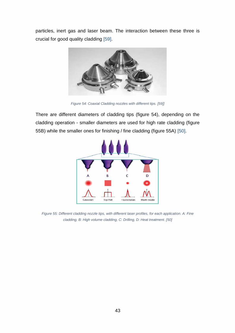
The Cladding Nozzle of the Hybrid System (continuous coaxial) is an extremely
important part of the system, because it is the “meeting point” of powder
43
particles, inert gas and laser beam. The interaction between these three is
crucial for good quality cladding [59].
Figure 54: Coaxial Cladding nozzles with different tips. [59]]
There are different diameters of cladding tips (figure 54), depending on the
cladding operation - smaller diameters are used for high rate cladding (figure
55B) while the smaller ones for finishing / fine cladding (figure 55A) [50].
Figure 55: Different cladding nozzle tips, with different laser profiles, for each application. A: Fine
cladding, B: High volume cladding, C: Drilling, D: Heat treatment. [50]
44
7. Hybrid manufacturing parameters and physics
7.1 Overview
After the decomposition of the Hybrid System, and the analysis of its main
components, the next step is to define the basic physics and parameters
equations for Machining (Chapter 7.2) and Directed Energy Deposition/Laser
Cladding (Chapter 7.3). Although identifying the basic underpinning physics of
these systems is not essential for understanding and analyzing the Hybrid-Lean
interaction, it offers a different viewpoint, which leads to a well-rounded base
for further research.
7.2 Mechanical Cutting [56]
The quality of mechanical cutting (machining) is determined by basic
operational parameters. Although, all the parameters about machining follow
the same basic principles, they differ according to each specific mechanical
cutting operation.
7.2.1 Important parameters
The important parameters of mechanical cutting that should be considered for
high quality cutting and productivity are the cutting speed, the feed speed, the
metal removal rate and the time required to perform the cutting. These
parameters depend on the kind of the cutting operation. An overview of these
cutting operations and their parameters is presented:
7.2.1.1 Milling
The milling processes are the most common and versatile in the Hybrid System.
The cutting tool is rotating, penetrates and removes material from the workpiece
(Figure 56).
45
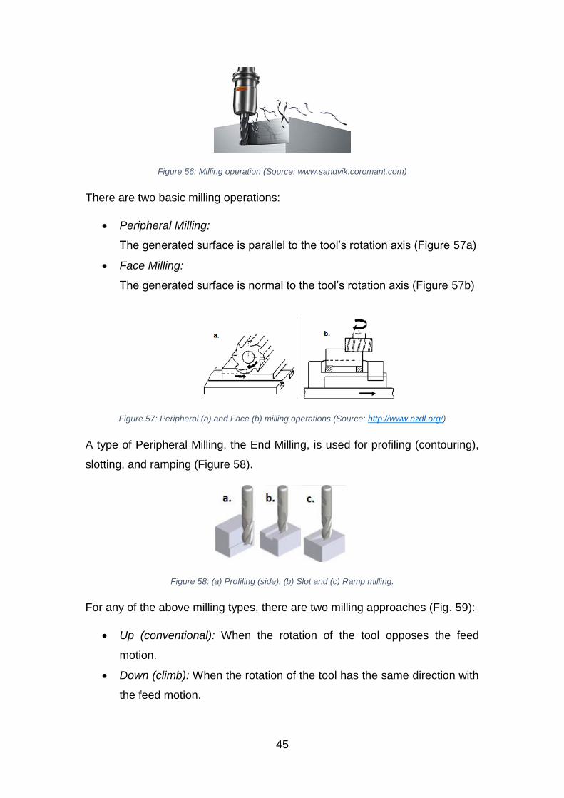
Figure 56: Milling operation (Source: www.sandvik.coromant.com)
There are two basic milling operations:
Peripheral Milling:
The generated surface is parallel to the tool’s rotation axis (Figure 57a)
Face Milling:
The generated surface is normal to the tool’s rotation axis (Figure 57b)
Figure 57: Peripheral (a) and Face (b) milling operations (Source: http://www.nzdl.org/)
A type of Peripheral Milling, the End Milling, is used for profiling (contouring),
slotting, and ramping (Figure 58).
Figure 58: (a) Profiling (side), (b) Slot and (c) Ramp milling.
For any of the above milling types, there are two milling approaches (Fig. 59):
Up (conventional): When the rotation of the tool opposes the feed
motion.
Down (climb): When the rotation of the tool has the same direction with
the feed motion.
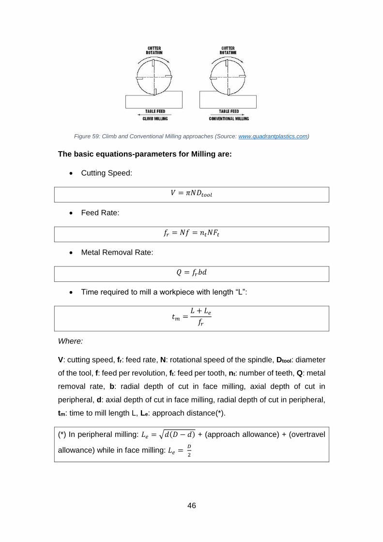
46
Figure 59: Climb and Conventional Milling approaches (Source: www.quadrantplastics.com)
The basic equations-parameters for Milling are:
Cutting Speed:
𝑉 = 𝜋𝑁𝐷𝑡𝑜𝑜𝑙
Feed Rate:
𝑓𝑟 = 𝑁𝑓 = 𝑛𝑡𝑁𝐹𝑡
Metal Removal Rate:
𝑄 = 𝑓𝑟𝑏𝑑
Time required to mill a workpiece with length “L”:
𝑡𝑚 =𝐿 + 𝐿𝑒
𝑓𝑟
Where:
V: cutting speed, fr: feed rate, N: rotational speed of the spindle, Dtool: diameter
of the tool, f: feed per revolution, ft: feed per tooth, nt: number of teeth, Q: metal
removal rate, b: radial depth of cut in face milling, axial depth of cut in
peripheral, d: axial depth of cut in face milling, radial depth of cut in peripheral,
tm: time to mill length L, Le: approach distance(*).
(*) In peripheral milling: 𝐿𝑒 = √𝑑(𝐷 − 𝑑) + (approach allowance) + (overtravel
allowance) while in face milling: 𝐿𝑒 = 𝐷
2
47
7.2.1.2 Drilling
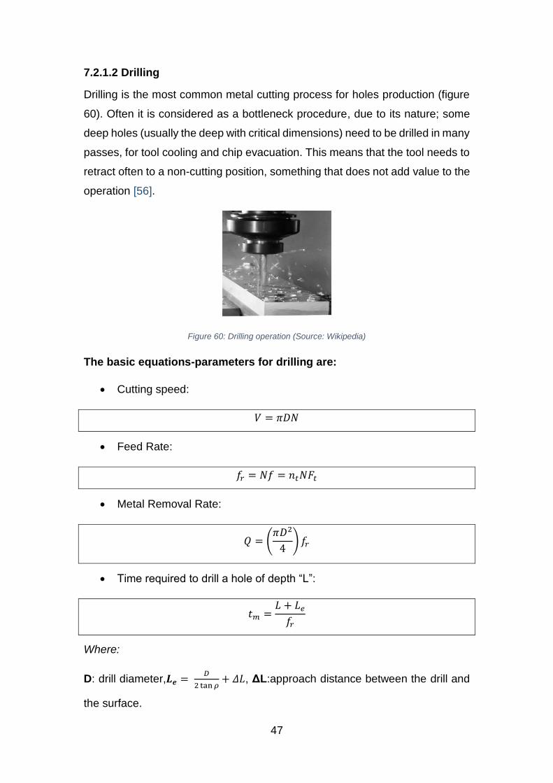
Drilling is the most common metal cutting process for holes production (figure
60). Often it is considered as a bottleneck procedure, due to its nature; some
deep holes (usually the deep with critical dimensions) need to be drilled in many
passes, for tool cooling and chip evacuation. This means that the tool needs to
retract often to a non-cutting position, something that does not add value to the
operation [56].
Figure 60: Drilling operation (Source: Wikipedia)
The basic equations-parameters for drilling are:
Cutting speed:
𝑉 = 𝜋𝐷𝑁
Feed Rate:
𝑓𝑟 = 𝑁𝑓 = 𝑛𝑡𝑁𝐹𝑡
Metal Removal Rate:
𝑄 = (𝜋𝐷2
4) 𝑓𝑟
Time required to drill a hole of depth “L”:
𝑡𝑚 =𝐿 + 𝐿𝑒
𝑓𝑟
Where:
D: drill diameter,𝑳𝒆 = 𝐷
2 tan 𝜌+ 𝛥𝐿, ΔL:approach distance between the drill and
the surface.
48
7.2.1.3 Boring
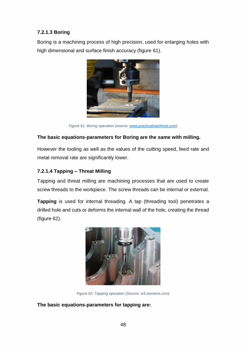
Boring is a machining process of high precision, used for enlarging holes with
high dimensional and surface finish accuracy (figure 61).
Figure 61: Boring operation (source: www.practicalmachinist.com)
The basic equations-parameters for Boring are the same with milling.
However the tooling as well as the values of the cutting speed, feed rate and
metal removal rate are significantly lower.
7.2.1.4 Tapping – Threat Milling
Tapping and threat milling are machining processes that are used to create
screw threads to the workpiece. The screw threads can be internal or external.
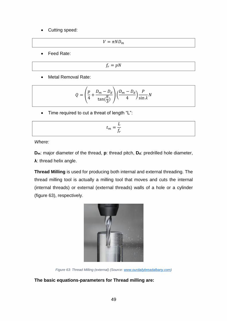
Tapping is used for internal threading. A tap (threading tool) penetrates a
drilled hole and cuts or deforms the internal wall of the hole, creating the thread
(figure 62).
Figure 62: Tapping operation (Source: w3.siemens.com)
The basic equations-parameters for tapping are:
49
Cutting speed:
𝑉 = 𝜋𝑁𝐷𝑚
Feed Rate:
𝑓𝑟 = 𝑝𝑁
Metal Removal Rate:
𝑄 = (𝑝
4+
𝐷𝑚 − 𝐷𝑑
tan(𝜋3
)) (
𝐷𝑚 − 𝐷𝑑
4)
𝑃
sin 𝜆𝑁
Time required to cut a threat of length “L”:
𝑡𝑚 =𝐿
𝑓𝑟
Where:
Dm: major diameter of the thread, p: thread pitch, Dd: predrilled hole diameter,
λ: thread helix angle.
Thread Milling is used for producing both internal and external threading. The
thread milling tool is actually a milling tool that moves and cuts the internal
(internal threads) or external (external threads) walls of a hole or a cylinder
(figure 63), respectively.
Figure 63: Thread Milling (external) (Source: www.ourdailybreadalbany.com)
The basic equations-parameters for Thread milling are:
50
Cutting Speed:
𝑉 = 𝜋𝑁𝐷
Feed Rate:
𝑓𝑟 = 𝑛𝑡𝑓𝑡𝑁𝐷𝑚−𝐷
𝐷𝑚 (For internal threads)
𝑓𝑟 = 𝑛𝑡𝑓𝑡𝑁𝐷𝜇−𝐷
𝐷𝜇 (For external threads)
Metal Removal Rate:
𝑄 = (𝑝
4+
𝐷𝑚 − 𝐷𝑑
tan 60) (
𝐷𝑚 − 𝐷𝑑
4) 𝑛𝑟𝑡𝑛𝑡𝑓𝑡𝑁
Time required to cut a threat of length “L” (one pass):
𝑡𝑚 = 1.1𝜋𝐷𝑝
𝑛𝑡𝑓𝑡𝑁 cos 𝜆
Where:
D: threading cutter major diameter, Dm: major diameters of the thread, Dμ: minor
diameter of the thread, nrt: rows of teeth in contact with the workpiece, Dp: pitch
diameter.
7.2.1.5 Reaming
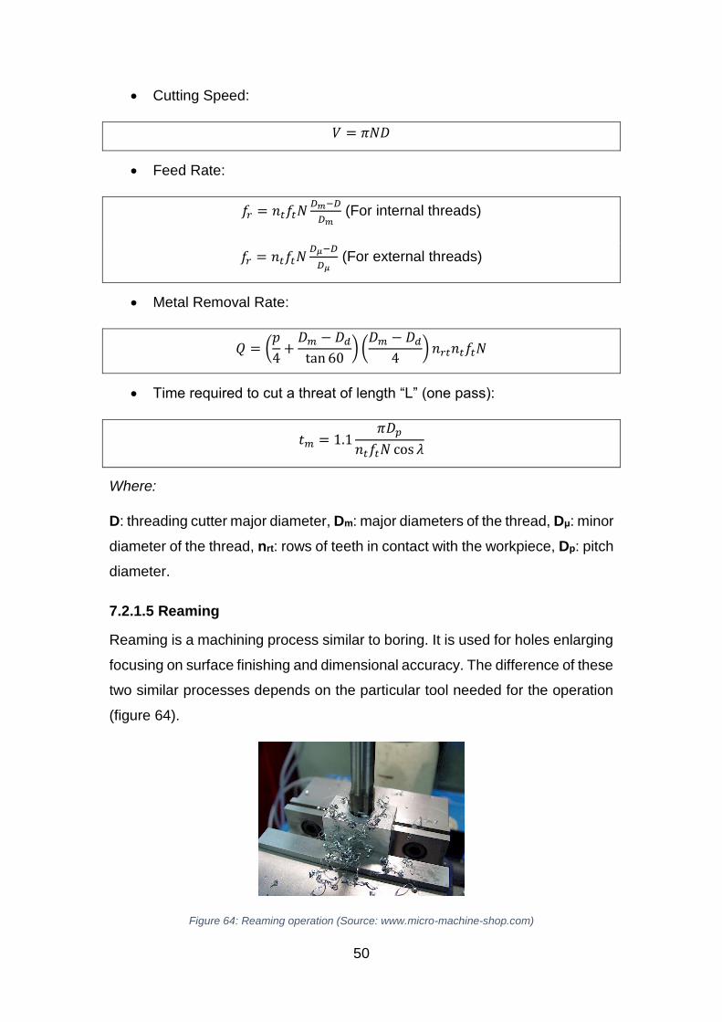
Reaming is a machining process similar to boring. It is used for holes enlarging
focusing on surface finishing and dimensional accuracy. The difference of these
two similar processes depends on the particular tool needed for the operation
(figure 64).
Figure 64: Reaming operation (Source: www.micro-machine-shop.com)
51
The basic equations-parameters for Reaming are the same with drilling.
However the tooling as well as the values of the cutting speed, feed rate and
metal removal rate are significantly lower.
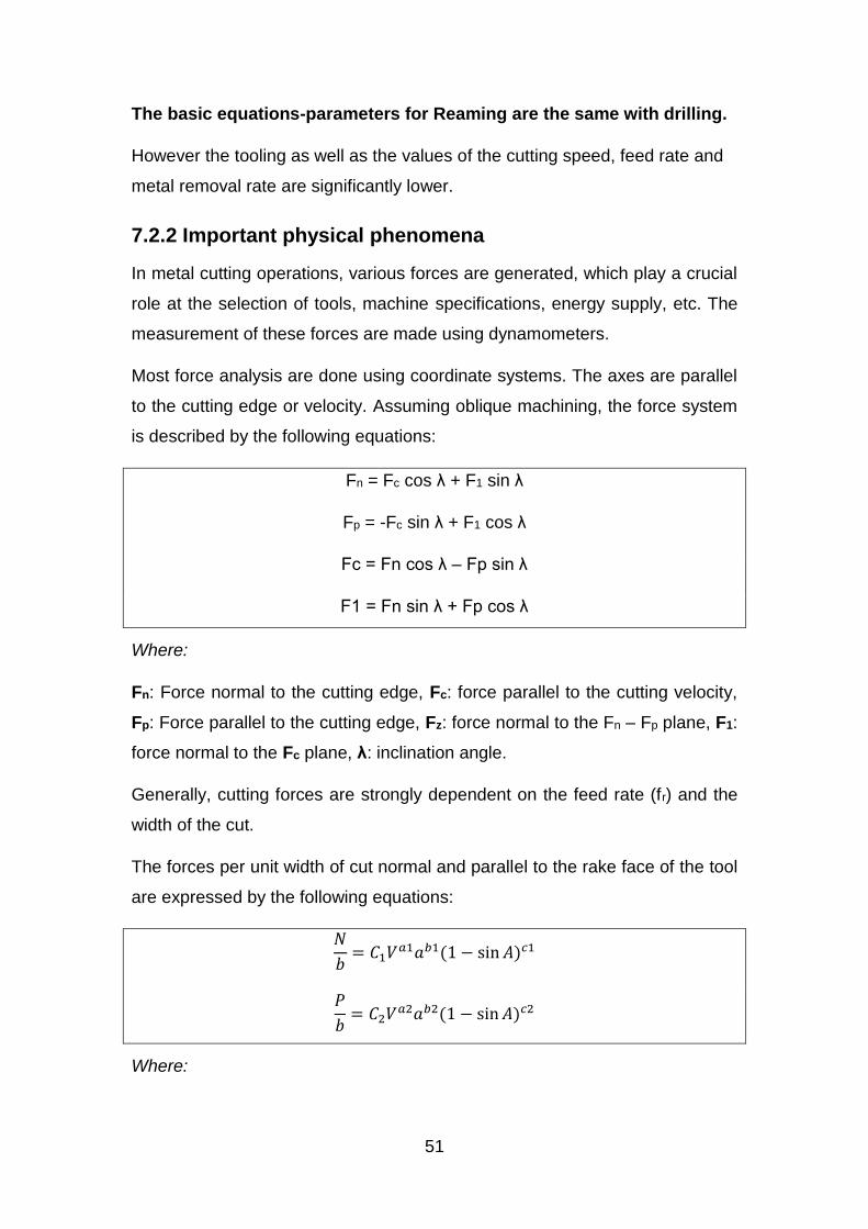
7.2.2 Important physical phenomena
In metal cutting operations, various forces are generated, which play a crucial
role at the selection of tools, machine specifications, energy supply, etc. The
measurement of these forces are made using dynamometers.
Most force analysis are done using coordinate systems. The axes are parallel
to the cutting edge or velocity. Assuming oblique machining, the force system
is described by the following equations:
Fn = Fc cos λ + F1 sin λ
Fp = -Fc sin λ + F1 cos λ
Fc = Fn cos λ – Fp sin λ
F1 = Fn sin λ + Fp cos λ
Where:
Fn: Force normal to the cutting edge, Fc: force parallel to the cutting velocity,
Fp: Force parallel to the cutting edge, Fz: force normal to the Fn – Fp plane, F1:
force normal to the Fc plane, λ: inclination angle.
Generally, cutting forces are strongly dependent on the feed rate (fr) and the
width of the cut.
The forces per unit width of cut normal and parallel to the rake face of the tool
are expressed by the following equations:
𝑁
𝑏= 𝐶1𝑉𝑎1𝑎𝑏1(1 − sin 𝐴)𝑐1
𝑃
𝑏= 𝐶2𝑉𝑎2𝑎𝑏2(1 − sin 𝐴)𝑐2
Where:
52
N: force normal to the tool rake face, P: force parallel to the tool rake face, α:
uncut chip thickness, b: width of cut, V: cutting speed, Α: normal rake angle,
and α1, α2, b1,b2, c1,c2, C1, C2 are coefficients, which are dependent on
combinations of tool materials and workpiece.
7.3 Laser Cladding [59]
7.3.1 Important parameters
The important parameters of laser cladding that should be considered for high
quality cladding and productivity are the dilution, the wetting angle, the aspect
ratio and the energy and powder density:
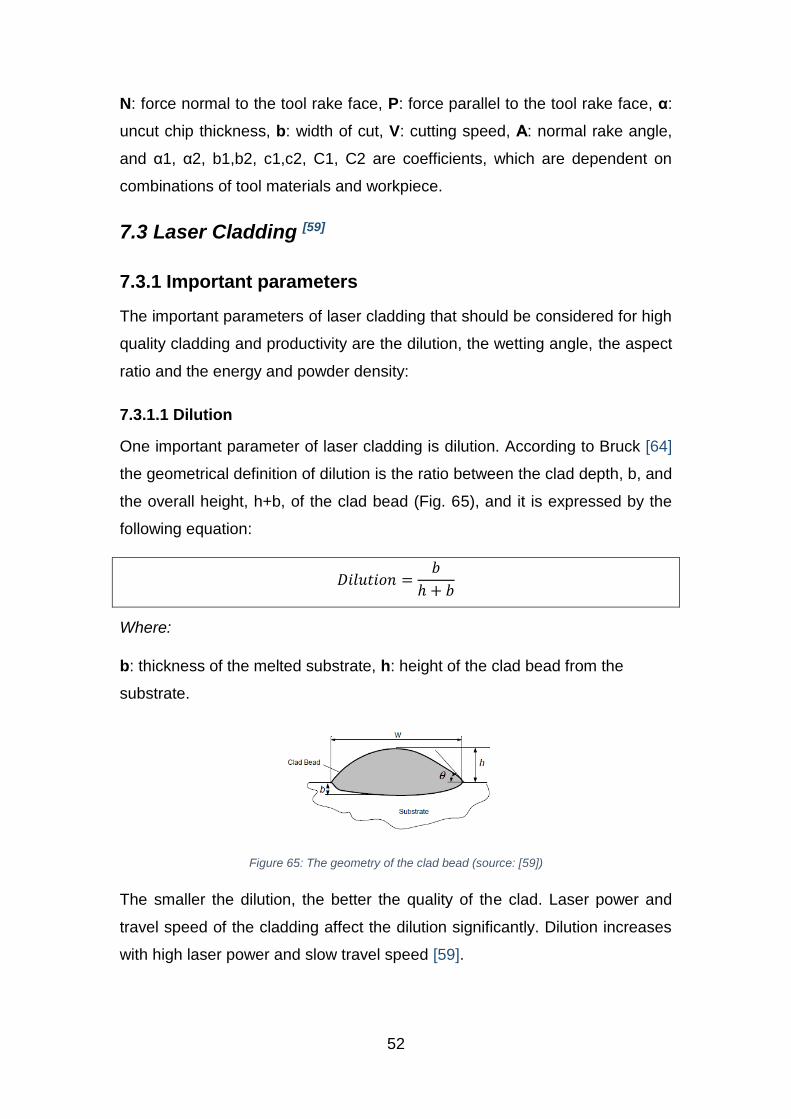
7.3.1.1 Dilution
One important parameter of laser cladding is dilution. According to Bruck [64]
the geometrical definition of dilution is the ratio between the clad depth, b, and
the overall height, h+b, of the clad bead (Fig. 65), and it is expressed by the
following equation:
𝐷𝑖𝑙𝑢𝑡𝑖𝑜𝑛 =𝑏
ℎ + 𝑏
Where:
b: thickness of the melted substrate, h: height of the clad bead from the
substrate.
Figure 65: The geometry of the clad bead (source: [59])
The smaller the dilution, the better the quality of the clad. Laser power and
travel speed of the cladding affect the dilution significantly. Dilution increases
with high laser power and slow travel speed [59].
53
7.3.1.2 Angle of wetting
The quality of the clad is also affected by the angle of wetting, θ. According to
the figure 65, the wetting angle is the angle between the substrate and the
created clad bead. The smaller the angle, the better the quality of the clad.
Laser power affect the wetting angle. High laser power increases dilution and
decreases the wetting angle.
Therefore, to achieve good clad quality low dilution and wetting is needed.
7.3.1.3 Aspect ratio
Aspect ratio is the ratio between the width (w) and the height (h) of the clad
bead, as shown in figure 63. It is expressed by:
𝐴𝑅 =𝑤
ℎ
Lasers in laser cladding can be continuous wave (CW) or pulsed. For each kind
of laser there are specific parameters:
7.3.1.4 Specific Energy and Powder Density (CW Lasers)
Specific energy and powder density are important parameters of CW lasers
which affect the clad quality.
𝐸𝑠𝑝𝑒𝑐𝑖𝑓𝑖𝑐 =𝑃𝑤
2𝑈𝑟𝑙
𝐺 =�̇�
2𝑈𝑟𝑙
Where:
Pw: laser power on the substrate, U: process speed, rl: laser beam radius.
�̇�: powder feed rate
7.3.1.5 Effective Energy Density and Effective powder deposition density
(Pulsed Lasers)
In pulsed lasers the parameters that must be considered are the effective
energy density and the effective powder deposition density.
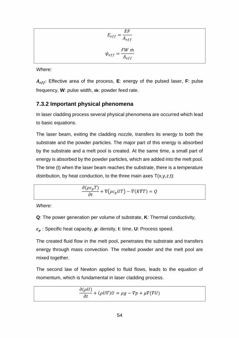
54
𝐸𝑒𝑓𝑓 =𝐸𝐹
𝐴𝑒𝑓𝑓
𝜓𝑒𝑓𝑓 =𝐹𝑊 �̇�
𝐴𝑒𝑓𝑓
Where:
𝑨𝒆𝒇𝒇: Effective area of the process, E: energy of the pulsed laser, F: pulse
frequency, W: pulse width, �̇�: powder feed rate.
7.3.2 Important physical phenomena
In laser cladding process several physical phenomena are occurred which lead
to basic equations.
The laser beam, exiting the cladding nozzle, transfers its energy to both the
substrate and the powder particles. The major part of this energy is absorbed
by the substrate and a melt pool is created. At the same time, a small part of
energy is absorbed by the powder particles, which are added into the melt pool.
The time (t) when the laser beam reaches the substrate, there is a temperature
distribution, by heat conduction, to the three main axes T(x,y,z,t):
𝜕(𝜌𝑐𝑝𝑇)
𝜕𝑡+ ∇(𝜌𝑐𝑝𝑈𝑇) − 𝛻(𝐾𝛻𝑇) = 𝑄
Where:
Q: The power generation per volume of substrate, K: Thermal conductivity,
𝒄𝒑 : Specific heat capacity, ρ: density, t: time, U: Process speed.
The created fluid flow in the melt pool, penetrates the substrate and transfers
energy through mass convection. The melted powder and the melt pool are
mixed together.
The second law of Newton applied to fluid flows, leads to the equation of
momentum, which is fundamental in laser cladding process.
𝜕(𝜌𝑈)
𝜕𝑡+ (𝜌𝑈𝛻)𝑈 = 𝜌𝑔 − 𝛻𝑝 + 𝜇𝛻(𝛻𝑈)
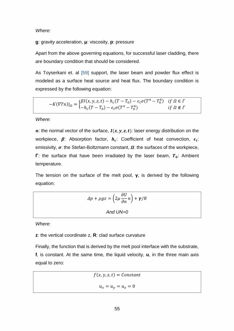
55
Where:
g: gravity acceleration, μ: viscosity, p: pressure
Apart from the above governing equations, for successful laser cladding, there
are boundary condition that should be considered.
As Toyserkani et. al [59] support, the laser beam and powder flux effect is
modeled as a surface heat source and heat flux. The boundary condition is
expressed by the following equation:
−𝐾(𝛻𝑇𝑛)|𝛺 = {𝛽𝐼(𝑥, 𝑦, 𝑧, 𝑡) − ℎ𝑐(𝑇 − 𝑇0) − 𝜖𝑡𝜎(𝛵4 − 𝛵0
4) 𝑖𝑓 𝛺 ∈ 𝛤
−ℎ𝑐(𝑇 − 𝑇0) − 𝜖𝑡𝜎(𝛵4 − 𝛵04) 𝑖𝑓 𝛺 ∉ 𝛤
Where:
𝒏: the normal vector of the surface, 𝑰(𝒙, 𝒚, 𝒛, 𝒕): laser energy distribution on the
workpiece, 𝜷: Absorption factor, 𝒉𝒄: Coefficient of heat convection, 𝝐𝒕:
emissivity, 𝝈: the Stefan-Boltzmann constant, 𝜴: the surfaces of the workpiece,
Γ: the surface that have been irradiated by the laser beam, 𝑻𝟎: Ambient
temperature.
The tension on the surface of the melt pool, γ, is derived by the following
equation:
𝛥𝑝 + 𝜌𝑔𝑧 = (2𝜇𝜕𝑈
𝜕𝑛𝑛) + 𝜸/𝑅
And UN=0
Where:
z: the vertical coordinate z, R: clad surface curvature
Finally, the function that is derived by the melt pool interface with the substrate,
f, is constant. At the same time, the liquid velocity, u, in the three main axis
equal to zero:
𝑓(𝑥, 𝑦, 𝑧, 𝑡) = 𝐶𝑜𝑛𝑠𝑡𝑎𝑛𝑡
𝑢𝑥 = 𝑢𝑦 = 𝑢𝑧 = 0
56
8. A Lean View of Hybrid Manufacturing
8.1 Introduction
The classification and knowledge mapping of manufacturing processes
(Chapters 2 and 3), the research on the selected existing and new paradigms
(Chapter 4 and 5), the modelling of the Hybrid System (Chapter 6) and the
understanding of the underpinning physics and equations of each sub-system
(Chapter 7), provides a strong base for the introduction of a new approach on
how we perceive Lean in a system – in this occasion, the Hybrid
System/Machine. Furthermore, this new approach is a test on how aware we
are about the limits of the Lean Manufacturing paradigm.
8.2 A novel approach
In the literature, it is easily perceived that the goal of Lean Manufacturing is to
optimize the whole value stream – of the manufacturing system/organization–
creating more value to the customers, while eliminating non-value adding
operations (wastes). Therefore, value stream is referred to the whole system
and it is all the actions required to be done, to create a product or service, from
concept/design to delivery [4, 31].
In this dissertation, the Hybrid System/Machine is investigated as a whole value
stream. Every part of the machine can be seen as an agent - subsystem - of
the whole system, which interacts with the other agents of the system.
Therefore, from this point of view, every component of the machine is
considered as a cell/machine station, every component’s action is considered
as a process, and the operation of the Hybrid machine (i.e. the manufacturing
of a part) of is considered as an entire value stream.
Based on this approach, the relationship between Hybrid and Lean can be
classified into two parts. The first part is to identify if the Hybrid System follows
the lean philosophy – how lean is it, at any time. The second part is to spot
wastes in the Hybrid System’s value stream, in order to eliminate them, and
make the system leaner. These two parts are connected under the Continuous
Improvement philosophy of Lean, as shown in figure 66. Continuous
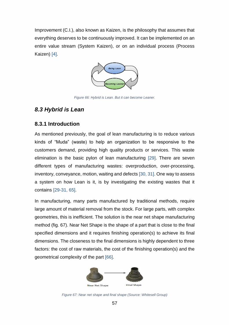
57
Improvement (C.I.), also known as Kaizen, is the philosophy that assumes that
everything deserves to be continuously improved. It can be implemented on an
entire value stream (System Kaizen), or on an individual process (Process
Kaizen) [4].
Figure 66: Hybrid is Lean. But it can become Leaner.
8.3 Hybrid is Lean
8.3.1 Introduction
As mentioned previously, the goal of lean manufacturing is to reduce various
kinds of “Muda” (waste) to help an organization to be responsive to the
customers demand, providing high quality products or services. This waste
elimination is the basic pylon of lean manufacturing [29]. There are seven
different types of manufacturing wastes: overproduction, over-processing,
inventory, conveyance, motion, waiting and defects [30, 31]. One way to assess
a system on how Lean is it, is by investigating the existing wastes that it
contains [29-31, 65].
In manufacturing, many parts manufactured by traditional methods, require
large amount of material removal from the stock. For large parts, with complex
geometries, this is inefficient. The solution is the near net shape manufacturing
method (fig. 67). Near Net Shape is the shape of a part that is close to the final
specified dimensions and it requires finishing operation(s) to achieve its final
dimensions. The closeness to the final dimensions is highly dependent to three
factors: the cost of raw materials, the cost of the finishing operation(s) and the
geometrical complexity of the part [66].
Figure 67: Near net shape and final shape (Source: Whitesell Group)
58
The traditional way of near-net shaping is usually from operations like casting,
forging or forming methods. The finishing is done with other kind of operations,
like milling, turning, drilling, boring, grinding, etc. This process chain requires
multiple machines, more operators, long lead times and high production costs.
Investigating from a Lean point of view, within this traditional process chain,
numerous wastes can be identified. On the other hand, Hybrid Manufacturing
seems to offer a Leaner way of manufacturing.
8.3.2 Seven Wastes: Traditional vs. Hybrid processes
By identifying the seven forms of waste into the traditional process chain
(casting/forging/forming followed by finishing) and comparing it with a Hybrid
Manufacturing (multitasking) machine, it would be clear that the new paradigm
of Hybrid Manufacturing can be a potential solution in waste minimization.
Waste of Over-production
The waste of over-production is when the production is more than what actually
the customer (external or internal) needs. This kind of waste is the most
important of all, due to the fact that it has an impact to the other six wastes [4].
Parts with complex geometries need multiple set ups. So, in a production (batch
or mass) there will be multiple setups in multiple machines. Each machine of
the process chain will over produce in order to keep the product flow and the
machine itself running. With a single setup in the Hybrid Machine the parts are
manufactured in a one –piece flow strategy, end-to-end. Therefore there is no
need to over-produce, to secure the continuous flow of products [2].
Waste of Over-processing
Over-processing is the kind of waste caused by performing additional
unnecessary processes, which do not add value to the production [4].
As mentioned above, using traditional methods to manufacture parts, needs
multiple setups. Between setups, specific processes are required to be done,
in order to facilitate the conditions of the next setup (process strategy-phases,
specific tolerances, design of jigs, manufacturing of jigs, deburring between
setups, etc.). Additional quality control checks are necessary between
59
processes, too. All these processes between setups are not required in a Hybrid
machine, due to the single setup. Moreover, prototyping – an expensive, time
consuming and wasteful process – either outsourced or in-site, adds non-value
adding processes in the value stream. Hybrid takes advantage of the benefits
that Additive Manufacturing provides, creating prototypes with reduced tooling
and setups, low costs and less time on “trial and error” processes of the
traditional prototyping techniques [2].
Waste of Inventory
Excess inventory refers to having more than the minimum needed stocks. It is
usually the result of over-production and it contributes to other wastes too, like
over-processing, conveyance and motion [4].
Using multiple machines with multiple setups, the presence of inventory is
essential to achieve the desired flow of products in the production. Inventories
are not adding value to the process and they are considered as wastes. With
single setup in the Hybrid Machine, inventory is not essential, and therefore is
eliminated. Concerning the inventory capacity, raw materials as well as net
shaped parts, need much space. On the other hand, Hybrid Machines need
powder (or wires), which need far less space in warehouses [2].
Waste of Conveyance
The waste of conveyance is occurred by moving parts, materials or equipment
unnecessarily [4].
When using multiple machines to manufacture a part, the transportation of the
part between stages is inevitable. Especially, for large parts, conveyance
requires extensive time, investment (cranes, lifters etc.), and additional
workforce. In a Hybrid machine, where the manufacturing of the component can
be done in a one single stage, there is no need for a non-value added part
transportation. Concerning raw material transportation, powders can be
transported easier, quicker and cheaper than blocks of raw materials, forgings
and castings [2].
60
Waste of Motion
When the employees or equipment make extra unnecessary movements to
perform a task, this is a waste of motion [4].
Using multiple machines with multiple setups, leads to waste of motion for both
the operators and the equipment. With setup elimination, they are not moving
more that is required to perform a specific task [2].
Waste of Waiting
Waste of waiting occurs when operators or equipment standing inactive or idle
respectively [4].
In a production line with more than one machines, there is always the possibility
of bottlenecks. Parts are waiting between production steps. The same happens
with the respective machines and operators. Moreover, there is waste of waiting
in every setup. With fewer machines, and eliminated setups, the cost of waiting
is minimized [2].
Waste of Defects (Rework)
Defects (or rework or correction) is one of the seven wastes of Lean philosophy
where the finished products does not meet the specifications / needs of the
customer (internal or external), and therefore there is a need for extra
inspection, rework and large percentage of scrap.
In every production step, there is the possibility of defective parts. If the
defected cannot be accepted by the quality control, the parts must be scrapped
or repaired. Defects add additional costs and non-value added processes on
the production. The elimination of setups reduces the possibility of defective
parts. In a hybrid machine, the part is manufactured end to end, with one setup,
leading to less variation in dimensional results [2]. Furthermore, if a defect is
inevitable, Hybrid manufacturing can provide an effective solution on repairing,
due to its ability to add material to the existing part. A typical example of
successful repair of part is the Reclaim project [42].
Summarizing, it is obvious that the multitasking nature of the Hybrid Technology
is consistent with the lean principles.
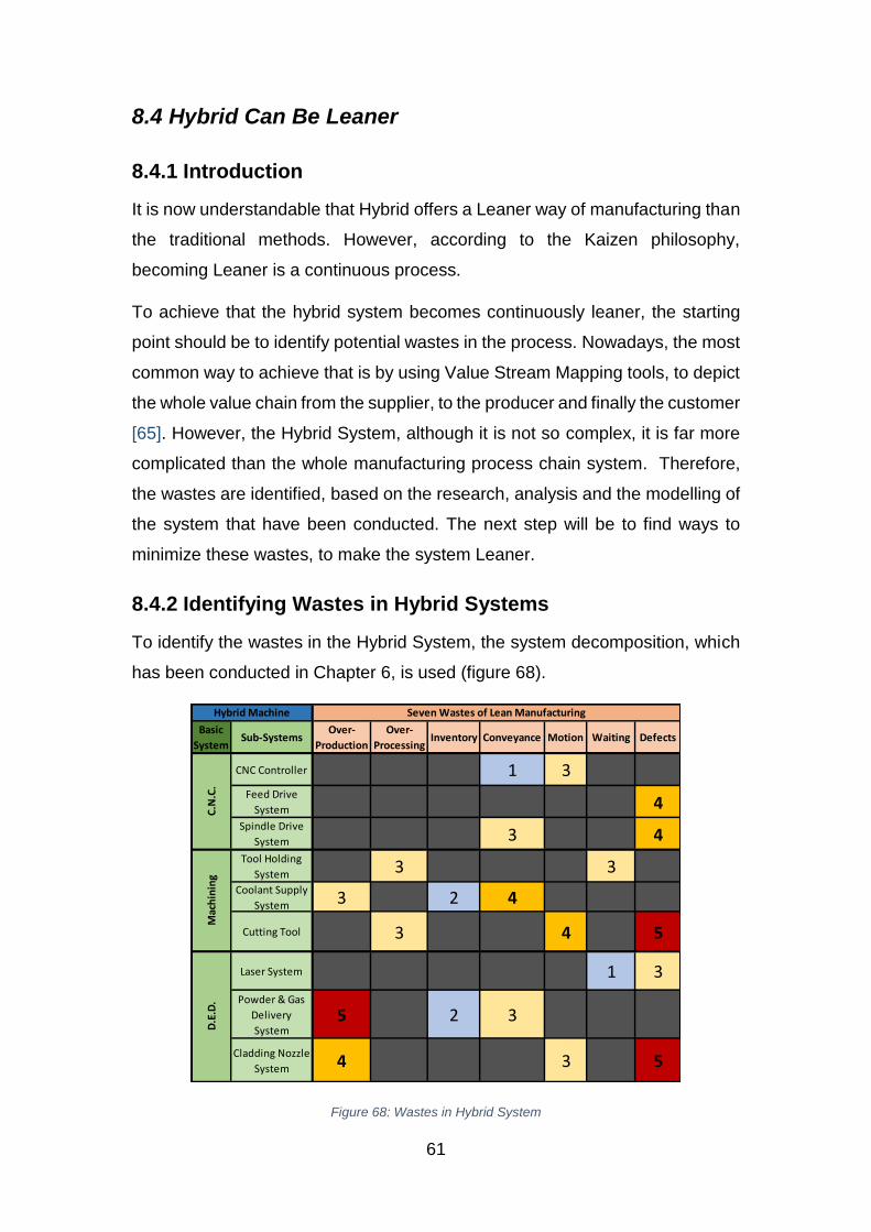
61
8.4 Hybrid Can Be Leaner
8.4.1 Introduction
It is now understandable that Hybrid offers a Leaner way of manufacturing than
the traditional methods. However, according to the Kaizen philosophy,
becoming Leaner is a continuous process.
To achieve that the hybrid system becomes continuously leaner, the starting
point should be to identify potential wastes in the process. Nowadays, the most
common way to achieve that is by using Value Stream Mapping tools, to depict
the whole value chain from the supplier, to the producer and finally the customer
[65]. However, the Hybrid System, although it is not so complex, it is far more
complicated than the whole manufacturing process chain system. Therefore,
the wastes are identified, based on the research, analysis and the modelling of
the system that have been conducted. The next step will be to find ways to
minimize these wastes, to make the system Leaner.
8.4.2 Identifying Wastes in Hybrid Systems
To identify the wastes in the Hybrid System, the system decomposition, which
has been conducted in Chapter 6, is used (figure 68).
Basic
SystemSub-Systems
Over-
Production
Over-
ProcessingInventory Conveyance Motion Waiting Defects
CNC Controller 1 3Feed Drive
System 4Spindle Drive
System 3 4Tool Holding
System 3 3Coolant Supply
System 3 2 4
Cutting Tool 3 4 5
Laser System 1 3
Powder & Gas
Delivery
System5 2 3
Cladding Nozzle
System 4 3 5
Hybrid Machine Seven Wastes of Lean Manufacturing
C.N
.C.
Mac
hin
ing
D.E
.D.
Figure 68: Wastes in Hybrid System

62
Based on this, the 9 subsystems that constitute the Hybrid Machine, have been
assessed regarding the kind of waste (boxes) and the importance/severity of
these wastes to the whole system's functionality.
The importance/severity of the wastes is in a 1-5 scale. Where 1 and 2 (light
blue color) are the less important wastes (does not have significant impact to
the system) and 4 and 5 (yellow and red respectively) are the wastes that have
the most impact on the system and they need to be eliminated. Using the above
table as a reference point, and the analysis/modelling of the previous chapters
as a base, the potential wastes of the sub-systems of the Hybrid systems are:
CNC Controller (Conveyance, Motion)
The CNC Controller, due to its complicated nature, is prone to the waste of
conveyance, concerning the electric energy and electrical signals
transportation. Numerous electric circuits, and wirings have been identified and
this might be a reason for the controller to underperform. A leaner CNC
Controller in terms of less wirings, less distance between the power supply and
the breakout board/drivers would be preferable.
Another waste is the waste of Motion. When the operator decide to move the
table to specific coordinates, electrical signals are send to the CNC controller,
and the drivers decide how to move the Feed Drive system. The way the drivers
will move the axis can affect lead times. The movement of the table to the
specific location should be the minimum needed. Especially at the rapid
movements of the table (G00 command of the G-Code).
Feed Drive System (Defects)
The Feed Drive System shows evidences of the waste of defects. Looking at
the feed drive system as a whole, when the actuators (motors) receive the
electrical signals from the drivers to move the table to a specific location, the
feed drive system executes this command, with some deviation. This deviation
can increase when the system is not well maintained, or at events of large
forces on the Lead/Ball screws (i.e. collisions).
63
Spindle System (Defects, Conveyance)
From the same point of view, Spindle System shows evidences of the waste of
defects. When the spindle drive system receive the signals from the driver,
there is deviation in the spindle speed. Moreover, there will be a potential runout
of the spindle. These deviations can be structural failures from the machine
vendor, or defects caused by significant forces applied to the spindle (i.e.
collisions).
The waste of conveyance is identified too. When a tool change performed, the
distance of the spindle and the tool changer of the spindle system (i.e. bracket,
robotic arm) should be minimized. This distance can affect the tool change
times, and therefore the lead times and the efficiency of the machine [51].
Tool Holding System (Over-Processing, Waiting)
The geometry and the working principles of the tool holding system can cause
over-processing. The more the components of the tool holder and the
operations needed to hold/tight the tool, the more time and effort are needed.
The simpler and quicker the tool holding procedure, the leaner the Tool Holding
System becomes [52, 56].
Another waste is waiting. When there is a need for changing the tool, or the
retaining device or even the pull stud, the machine should stop its operation
(external operation). This causes downtimes of the machine as a whole. An
automated procedure of tool change on the holder, would make the system
leaner. An example of potential solution can be an automated integrated Heat
Shrink machine to the tool changer/tool storage.
Coolant Supply System (Over-Production, Inventory, Conveyance)
One of the wastes of the Coolant supply system is the over-production, in
terms of the quantity of coolant provided to the cutting point. There is a specific
amount of coolant needed for each operation, to achieve good lubrication,
temperature and chip evacuation. The excess coolant is unnecessary and
therefore it is consider as waste. Moreover, large amounts of coolant maybe
will cause bad conditions inside the chamber for the cladding process.
64
Inventory is an important waste in the coolant supply system. As shown in
chapter 6, the coolant follows a continuous cycle. Depending the machine –
and therefore the length of this cycle – there is a specific minimum amount of
coolant needed to fulfill this cycle. Taking into consideration the potential
coolant losses (vaporization, small amounts of coolant on the walls/parts/tools,
etc.) there is only a small amount of needed coolant inventory. The excess
coolant in the tank has no value, and is considered as waste.
Conveyance of the coolant is another form of waste and is highly associated
with the length of the delivery route. The less the distance between the
tank/pump and the orifice, the leaner the coolant supply system is.
Cutting Tool (Over-Processing, Motion, Defects)
The material removal should always add value to the whole process. That
means that unnecessary tool movements are considered as a waste of over-
processing. These movements can be additional unnecessary toolpaths, non-
optimal starting and end points of the tools, unnecessary remoted retract points
or dwelling and pauses for checking, etc.
Moreover, the cutting tool should be selected by its removal rate, to minimize
the additional cutting operations (additional cutting cycles). The over-
processing waste generates the waste of Motion. When the material removal
is non optimal and the cutting operations are multiplied, this causes
unnecessary movements of the cutting tool (additional toolpaths) to perform its
task (material removal to the desired dimensions), which are not adding value
to the whole operation.
Not only material removal should be under consideration when choosing the
cutting tool. The cutting conditions (spindle speed, feed speed, etc.), the
geometry, material and coating are important. Bad decisions on these factors
can cause significant tool wear or even breakage. Moreover, the defects can
be found on the workpiece too, increasing the cost, time and quality of the whole
operation.
65
Laser System (Waiting, Defects)
Analyzing the underpinning physics of Laser generation, it is well understood
that to generate the laser beam many procedures must be done. This can be
time consuming and it can cause waiting to the whole system until the laser
generator can produce the laser beam needed (power, beam quality, etc.).
For a successful laser cladding, the quality of the beam, the reflection of the
laser from metallic surfaces and the temperature are critical factors [59]. If one
of these is not the appropriate there will be defects in the workpiece. Defects
of the laser quality causes defects on the workpiece. Furthermore, laser power
can affect the quality of the cladding, because it affects the values of dilution
and wetting angle.
Powder and Gas Delivery System (Over-Production, Inventory, Conveyance)
Over-production is one of the wastes of this system, in terms of the quantity
of powder that is delivered to the cladding point each time. There is a specific
quantity of powder (powder feed rate) that is needed for successful cladding
and it depends on the deposition rate that is required to be achieved. Excessive
powder supply, offers no value (waste), due to the fact that the excess powder
particles will not absorb enough energy to be cladded (low capture efficiency).
Powder materials are expensive, therefore capture efficiency has a big
importance.
Excess inventory (mostly concerning powder) is, also, a waste. The amount of
powder needed for the machine’s operation is (or should be) known at the
beginning of the process, and it depends on the size of the workpiece, the
capture efficiency and the deposition volume/rate. Therefore, the volume of
powder stored in the feeder should not excess the volume that is required,
because it adds no value to the process.
The waste of Conveyance depends on the supply route of the powder. The
shortest the route between powder feeder and powder supply nozzle, the leaner
the system becomes.
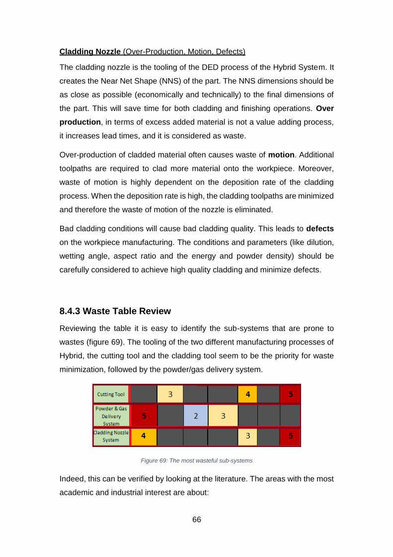
66
Cladding Nozzle (Over-Production, Motion, Defects)
The cladding nozzle is the tooling of the DED process of the Hybrid System. It
creates the Near Net Shape (NNS) of the part. The NNS dimensions should be
as close as possible (economically and technically) to the final dimensions of
the part. This will save time for both cladding and finishing operations. Over
production, in terms of excess added material is not a value adding process,
it increases lead times, and it is considered as waste.
Over-production of cladded material often causes waste of motion. Additional
toolpaths are required to clad more material onto the workpiece. Moreover,
waste of motion is highly dependent on the deposition rate of the cladding
process. When the deposition rate is high, the cladding toolpaths are minimized
and therefore the waste of motion of the nozzle is eliminated.
Bad cladding conditions will cause bad cladding quality. This leads to defects
on the workpiece manufacturing. The conditions and parameters (like dilution,
wetting angle, aspect ratio and the energy and powder density) should be
carefully considered to achieve high quality cladding and minimize defects.
8.4.3 Waste Table Review
Reviewing the table it is easy to identify the sub-systems that are prone to
wastes (figure 69). The tooling of the two different manufacturing processes of
Hybrid, the cutting tool and the cladding tool seem to be the priority for waste
minimization, followed by the powder/gas delivery system.
Figure 69: The most wasteful sub-systems
Indeed, this can be verified by looking at the literature. The areas with the most
academic and industrial interest are about:

67
The metal cutting conditions, tool wearing, tool-chip interface, toolpath
optimization, tools’ materials and coatings [67-71].
The cladding conditions and laser – particles – workpiece interaction [59,
72-76].
Laser Cladding powder delivery management, transportation, powder
feed rate and way of supply (coaxial, lateral, etc.) [59, 63, 72-75, 77].
Reviewing the existing literature, the wastes of Figure 69 can be verified.
Moreover, it has value to identify the most common kind of waste in the Hybrid
System.
Figure 70: Hybrid is prone to the Waste of defects
Reviewing the table of wastes (figure 68), it is obvious that the waste of defects
is the most common and the most serious kind of waste in the system (figure
70). Actually, defects are the main concern of both academia and industry. Tool
wearing, surface finishing, workpiece microstructure, porosity and density are
fields that are prone to defects, and therefore are topics for studies and
researches.
68
9. Discussion
In this dissertation a number of topics are reviewed and investigated.
A review on process classification, in chapter 2, is deducted and a holistic and
objective classification approach is selected (Alting’s process classification).
Using this classification, a manufacturing knowledge map is created (chapter
3) and enriched with the new paradigms of the recent years (Lean
Manufacturing, Additive Manufacturing).
Four manufacturing paradigms are selected and reviewed in chapter 4:
Computer Numerical Control, Subtractive Manufacturing, Additive
Manufacturing and Lean Manufacturing. The understanding of these
paradigms, gives the opportunity to review (chapter 5), analyze and model
(chapter 6 and 7) the Hybrid Manufacturing System. The Hybrid System is
decomposed into three main systems (Computer Numerical Control, Additive
and Subtractive Manufacturing). Each of these systems are decomposed into
their own sub-systems, and so on. The aim of this method is to identify how the
sub-systems interact to each other (like agents), understanding the flow of
operations inside the system.
Understanding the flow, gives the opportunity to treat the Hybrid System as a
value stream. Each component/subsystem of the Hybrid System, is part of this
stream and adds value to it. If an operation of a subsystem does not add value
to the value stream is considered as waste. The seven wastes of lean
manufacturing provide a useful platform for the system’s lean assessment
(Chapter 8). In all of the subsystems potential wastes are identified and
presented. The outcome was that the subsystems that requires the most
attention is the cutting tool, the cladding nozzle and the powder/gas delivery
system. Furthermore, the most common and severe kind of waste is the waste
of defects, something that can be verified by the plenty of literature available in
these subjects.
69
10. Conclusion & Future Work
In this dissertation, the interaction between Hybrid and Lean Manufacturing is
investigated. The aim is to identify if Hybrid is lean “by nature” –comparing to
traditional processes- and if yes, how it can be leaner.
To achieve these two goals the Hybrid System is decomposed into subsystems,
and modelled following an agent based modelling (Receive-Decide-Act).
The Hybrid machine, as the epitome of multitasking machine, shows strong
evidences of a lean thinking compliance. Identifying that Hybrid has the
potential to be a process that follows the Lean philosophy, the next step is to
assess how lean it is, in terms of wastes recognized in each of its subsystems.
The outcome is that three sub-systems (the cutting tool, the cladding nozzle
and the powder/gas delivery system) need to become leaner in order to lead
the whole system becoming leaner. Moreover, the waste of defects is the most
frequent waste identified, in terms of workpiece defects as well as tool wearing
and feed and spindle drive accuracy.
During this research, numerous opportunities arose for taking this topic further.
The first opportunity is in the field of Hybrid Manufacturing. This paradigm is
new and few research papers and books are released, most of them after 2013.
Fields like powder efficiency, laser-powder interaction, and quick tool
changeover will enhance the knowledge about this topic. Another opportunity
is in the field of Lean manufacturing. Lean is mostly used to optimize the whole
value stream of an organization or manufacturing system. This dissertation
shows a novel way to implement lean inside the machine system, dealing with
each part of the machine as a discrete workstation with specific duties. Finally,
process mapping is a field that needs to be subject of research. Visual
understanding is an important aspect of manufacturing engineering, providing
a string base for analysis of existing and generation of new paradigms.
70
11. References
[1] Zhu, Z., Dhokia, V., Nassehi, A. and Newman, S. (2013). A review of hybrid
manufacturing processes – state of the art and future perspectives.
International Journal of Computer Integrated Manufacturing, 26(7), pp.596-615.
[2] Rivera, M. (2015). Large CNC 3+2 Machining, Lean Manufacturing and the
Seven Forms of Waste - K&M Machine-Fabricating, Inc.. [online] K&M
Machine-Fabricating, Inc. Available at: http://www.k-mm.com/news/large-cnc-
32-machining-lean-manufacturing-seven-forms-waste/ [Accessed 7 Aug.
2016].
[3] Feld, W. (2001). Lean manufacturing. Boca Raton, FL: St. Lucie Press.
[4] Marchwinski, C. and Shook, J. (2003). Lean lexicon. Brookline, Mass.: Lean
Enterprise Institute.
[5] Swift, K. and Booker, J. (2003). Process selection. Oxford [England]:
Butterworth-Heinemann.
[6] Kalpakjian, S. and Schmid, S. (2014). Manufacturing engineering and
technology.
[7] Groover, M. (2010). Fundamentals of modern manufacturing. Hoboken, NJ:
J. Wiley & Sons.
[8] Nassehi, A., Newman, S.T., Dhokia, V.G., Zicheng Zhu, Z. (2011). Using
formal methods to model hybrid manufacturing processes. In: 4th international
conference on changeable, agile, reconfigurable and virtual production
(CARV2011), 2–5 October, Montreal, Canada.
[9] Alting, L. and Boothroyd, G. (1982). Manufacturing engineering processes.
New York: M. Dekker.
[10] Wood, R.L. (2015). Manufacturing System and Process Modelling,
MMP105, Loughborough University, Loughborough.
[11] Wood, R.L. (n.d.). A dynamic curation method for manufacturing related
knowledge. Wolfson School of Mechanical, Manufacturing and Electrical
Engineering, Loughborough University, Loughborough.
71
[12] Youssef, H. and El-Hofy, H. (2008). Machining technology. Boca Raton, Fl:
CRC Press.
[13] Li, Y., Lee, C. and Gao, J. (2015). From computer-aided to intelligent
machining: Recent advances in computer numerical control machining
research. Proceedings of the Institution of Mechanical Engineers, Part B:
Journal of Engineering Manufacture, 229(7), pp.1087-1103.
[14] Wan, J., Li, D., Tu, Y. and Zhang, C. (2011). Performance analysis model
for real-time Ethernet-based computer numerical control system. Journal of
Central South University of Technology, 18(5), pp.1545-1553.
[15] Zhang, Z., Song, J., Liu, Y. and Xu, D. (2015). An integrated
multidisciplinary design optimization method for computer numerical control
machine tool development. Advances in Mechanical Engineering, 7(2).
[16] El-Hofy, H. (2014). Fundamentals of machining processes.
[17] Brinksmeier, E. and Gläbe, R. (2001). Advances in Precision Machining of
Steel. CIRP Annals - Manufacturing Technology, 50(1), pp.385-388.
[18] Li, H., He, G., Qin, X., Wang, G., Lu, C. and Gui, L. (2014). Tool wear and
hole quality investigation in dry helical milling of Ti-6Al-4V alloy. The
International Journal of Advanced Manufacturing Technology, 71(5-8),
pp.1511-1523.
[19] Fan, Y., Hao, Z., Zheng, M., Sun, F. and Yang, S. (2013). Study of surface
quality in machining nickel-based alloy Inconel 718. The International Journal
of Advanced Manufacturing Technology, 69(9-12), pp.2659-2667.
[20] Fan, X. and Loftus, M. (2007). The influence of cutting force on surface
machining quality. International Journal of Production Research, 45(4), pp.899-
911.
[21] Shokrani, A., Dhokia, V., Muñoz-Escalona, P. and Newman, S. (2013).
State-of-the-art cryogenic machining and processing. International Journal of
Computer Integrated Manufacturing, 26(7), pp.616-648
[22] Gibson, I., Rosen, D. and Stucker, B. (2010). Additive manufacturing
technologies.
72
[23] Kay, R. (2015). Introduction to Additive Manufacturing, MMP637,
Loughborough University, Loughborough, 3 November.
[24] Hopkinson, N., Hague, R., Dickens, P. (2006). Rapid Manufacturing: An
Industrial Revolution for the Digital Age. John Wiley, Chichester, England.
[25] Hopkinson, N., Hague, R., Dickens, P. (2006). Rapid Manufacturing: An
Industrial Revolution for the Digital Age. John Wiley, Chichester, England.
[26] Atzeni, E. and Salmi, A. (2012). Economics of additive manufacturing for
end-usable metal parts. The International Journal of Advanced Manufacturing
Technology, 62(9-12), pp.1147-1155.
[27] Hague, R., Mansour, S. and Saleh, N. (2004). Material and design
considerations for rapid manufacturing. International Journal of Production
Research, 42(22), pp.4691-4708.
[28] Bhamra, R. (2016). Lean and Agile Manufacturing, MMP233,
Loughborough University, Loughborough, 22 February.
[29] Pavnaskar, S., Gershenson, J. and Jambekar, A. (2003). Classification
scheme for lean manufacturing tools. International Journal of Production
Research, 41(13), pp.3075-3090.
[30] Shingo, S. (1992). The Shingo Prize Production Management System:
Improving Process Functions. (Cambridge, MA: Productivity Press).
[31] Womack, J. P., Jones, D. T., & Roos, D. (1990). The machine that changed
the world. Toronto, Canada: Collier Macmillan ISBN 0892563508.
[32] Ohno, T. (1988). The Toyota production system: Beyond large-scale
production. Portland: Productivity Press.
[33] Hines, P., Holweg, M. and Rich, N. (2004), Learning to evolve – a review
of contemporary lean thinking. International Journal of Operations & Production
Management, Vol. 24 No. 10, pp. 994-1011.
[34] Shah, R. and Ward, P.T. (2003). Lean manufacturing: context, practice
bundles, and performance. Journal of Operations Management, Vol. 21 No. 2,
pp. 129-149.
73
[35] Moyano-Fuentes, J. and Sacristan-Diaz, M. (2012). Learning on lean: a
review of thinking and research. International Journal of Operations &
Production Management, Vol. 32 No. 5, pp. 551-582.
[36] Papadopoulou, T.C. and Ozbayrak, M. (2005). Leanness: experiences
from the journey to date. Journal of Manufacturing Technology Management,
Vol. 16 No. 7, pp. 784-807.
[37] Molitch-Hou, M. (2014). Mazak Adds Hybrid Metal 3D Printer to Machine
Tool Lineup. Available from: http://3dprintingindustry.com/2014/11/04/mazak-
hybrid-metal-3d-printer/.
[38] Woodcock, J. (2014). Euromold roundup - bigger, bolder, busier. Available
from: http://www.tctmagazine.com/blogs/jwblog/euromold-roundup-2013/.
[39] Lorenz, K. A., Jones, J.B., Wimpenny, D.I., Jackson, M. R. (2015). A review
of Hybrid Manufacturing.
[40] Lauwers, B., Klocke, F., Klink, A., Tekkaya, A., Neugebauer, R. and
Mcintosh, D. (2014). Hybrid processes in manufacturing. CIRP Annals -
Manufacturing Technology, 63(2), pp.561-583.
[41] Nowotny, S., Muenster, R., Scharek, S. and Beyer, E. (2010). Integrated
laser cell for combined laser cladding and milling. Assembly Automation, 30(1),
pp.36-38.
[42] Jones, J., McNutt, P., Tosi, R., Perry, C. and Wimpenny, D. (2015).
Remanufacture of turbine blades by laser cladding, machining and in-process
scanning in a single machine.
[43] Overby, A. (2011). CNC machining handbook. New York: McGraw-Hill.
[44] Slocum, A. (2008). Fundamentals of Design. Massachusetts Institute of
Technology (M.I.T.)
[45] MultiCam Canada (2012). [Online] Available at:
https://multicamcanada.wordpress.com [Accessed 18 Jul. 2016].
[46] Helixlinear.com (n.d.). Helix Linear Technologies. [Online] Available at:
http://www.helixlinear.com/ [Accessed 18 Jul. 2016].
74
[47] Busch-Vishniac, I. (1999). Electromechanical sensors and actuators. New
York: Springer.
[48] Hughes, A. (2006). Electric motors and drives. Amsterdam:
Elsevier/Newnes.
[49] Cvel.clemson.edu. (n.d.). Clemson Vehicular Electronics Laboratory.
[Online] Available at: http://www.cvel.clemson.edu/ [Accessed 19 Jul. 2016].
[50] Jones, J. (2016). Repurposing mainstream CNC machine tools for laser-
based additive manufacturing.
[51] Kim, J. and Lee, C. (2012). Multi-stage optimum design of magazine type
automatic tool changer arm. Journal of Central South University, 19(1), pp.174-
178.
[52] Mscdirect.com. (2016). MSC Industrial Supply Co. [Online] Available at:
http://www.mscdirect.com [Accessed 24 Jul. 2016].
[53] Thegeekgroup.org. (2016). The Geek Group. [Online] Available at:
http://thegeekgroup.org/ [Accessed 24 Jul. 2016].
[54] Evans, K. (2007). Programming of computer numerically controlled
machines. New York: Industrial Press.
[55] Fleischer, J., Denkena, B., Winfough, B. and Mori, M. (2006). Workpiece
and Tool Handling in Metal Cutting Machines. CIRP Annals - Manufacturing
Technology, 55(2), pp.817-839.
[56] Stephenson, D. and Agapiou, J. (2006). Metal cutting theory and practice.
Boca Raton, FL: CRC Taylor & Francis.
[57] Schawlow, A. and Townes, C. (1958). Infrared and Optical Masers. Phys.
Rev., 112(6), pp.1940-1949.
[58] Einstein, A. (1916). Strahlungs-emission und -absorption nach der
Quantentheorie. Verh Dtsch Phys Ges, 18:318-323.
[59] Toyserkani, E., Khajepour, A. and Corbin, S. (2005). Laser cladding. Boca
Raton, Fl.: CRC Press.
[60] Hecht, J. (1994). Understanding lasers. New York: IEEE Press.
75
[61] Steen, W. and Mazumder, J. (2010). Laser material processing. London:
Springer.
[62] Suder, W. and Williams, S. (2012). Investigation of the effects of basic laser
material interaction parameters in laser welding. Journal of Laser Applications,
24(3), p.032009.
[63] Lamikiz, A., Tabernero, I., Ukar, E., Martinez, S. and N. Lopez de Lacalle,
L. (2011). Current Designs of Coaxial Nozzles for Laser Cladding. Recent
Patents on Mechanical Engineering, 4(1), pp.29-36.
[64] Bruck, G.J. (1988). Fundamentals and industrial applications of high power
laser beam cladding. Laser Beam Surface Treating and Coating, G. Sepold,
Ed., pp. 14—28. SPIE 957.
[65] Jones, D. and Womack, J. (2000). Seeing the whole. Brookline, MA.: Lean
Enterprise Inst.
[66] Bodycote.com. (2016). Near-net-shape (NNS) - Bodycote Technical
Glossary [Online]. Available at: http://www.bodycote.com/en/site-
services/technical-glossary/nns.aspx [Accessed 16 Aug. 2016].
[67] Puls, H., Klocke, F. and Lung, D. (2014). Experimental investigation on
friction under metal cutting conditions. Wear, 310(1-2), pp.63-71.
[68] Robinson, G., Jackson, M. and Whitfield, M. (2007). A review of machining
theory and tool wear with a view to developing micro and nano machining
processes. J Mater Sci, 42(6), pp.2002-2015.
[69] Zhang, L. (2011). Process modeling and toolpath optimization for five-axis
ball-end milling based on tool motion analysis. The International Journal of
Advanced Manufacturing Technology, 57(9-12), pp.905-916.
[70] Toolpath optimization for minimizing airtime during machining. (2004).
Journal of Manufacturing Systems, 23(4), p.331.
[71] Thepsonthi, T. and Özel, T. (2014). An integrated toolpath and process
parameter optimization for high-performance micro-milling process of Ti–6Al–
4V titanium alloy. The International Journal of Advanced Manufacturing
Technology, 75(1-4), pp.57-75.
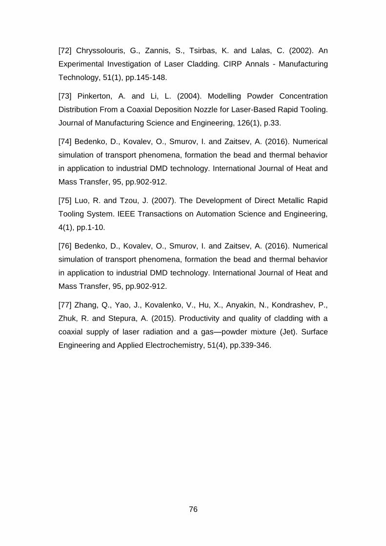
76
[72] Chryssolouris, G., Zannis, S., Tsirbas, K. and Lalas, C. (2002). An
Experimental Investigation of Laser Cladding. CIRP Annals - Manufacturing
Technology, 51(1), pp.145-148.
[73] Pinkerton, A. and Li, L. (2004). Modelling Powder Concentration
Distribution From a Coaxial Deposition Nozzle for Laser-Based Rapid Tooling.
Journal of Manufacturing Science and Engineering, 126(1), p.33.
[74] Bedenko, D., Kovalev, O., Smurov, I. and Zaitsev, A. (2016). Numerical
simulation of transport phenomena, formation the bead and thermal behavior
in application to industrial DMD technology. International Journal of Heat and
Mass Transfer, 95, pp.902-912.
[75] Luo, R. and Tzou, J. (2007). The Development of Direct Metallic Rapid
Tooling System. IEEE Transactions on Automation Science and Engineering,
4(1), pp.1-10.
[76] Bedenko, D., Kovalev, O., Smurov, I. and Zaitsev, A. (2016). Numerical
simulation of transport phenomena, formation the bead and thermal behavior
in application to industrial DMD technology. International Journal of Heat and
Mass Transfer, 95, pp.902-912.
[77] Zhang, Q., Yao, J., Kovalenko, V., Hu, X., Anyakin, N., Kondrashev, P.,
Zhuk, R. and Stepura, A. (2015). Productivity and quality of cladding with a
coaxial supply of laser radiation and a gas—powder mixture (Jet). Surface
Engineering and Applied Electrochemistry, 51(4), pp.339-346.
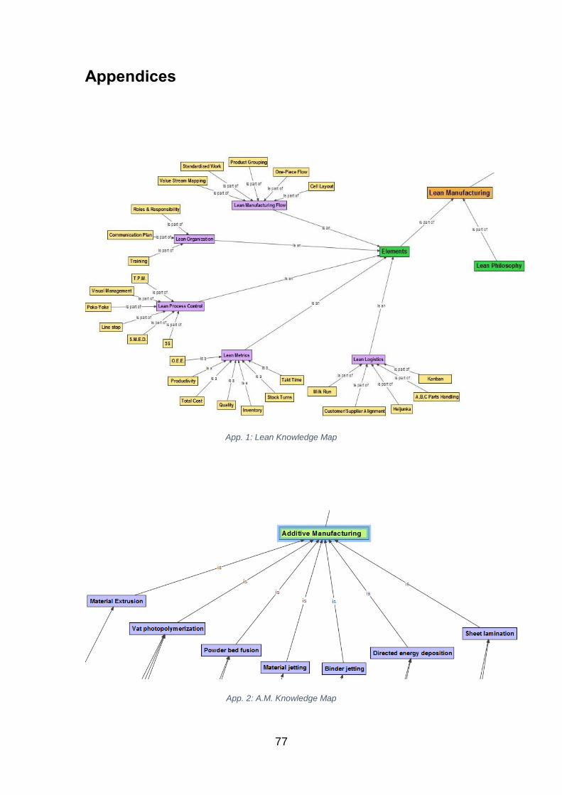
77
Appendices
App. 1: Lean Knowledge Map
App. 2: A.M. Knowledge Map

78
Acknowledgements
This dissertation was carried out during the years 2015-2016 at Loughborough
University. All this work would not have been possible without the support of
many people.
First of all I would like to thank my supervisor, Mr. R.L. Wood, who accepted
and encouraged my idea about this dissertation.
I would like, also, to express my gratitude to all the lecturers of the M.Sc. in
Advanced Manufacturing Engineering and Management, for their support,
advices and inspiration.
Last, but not least, I would like to thank my family and my friends for their
support, without which, none of these would be possible.