ad-a207 392 - defense technical information center · ad-a207 392 aefa project no ... the safe...
TRANSCRIPT
AD-A207 392AEFA Project No. 87-13
VERIFICATION OF THE PRODUCTION SAFE FLIGHTINSTRUMENT CORPORATION OV/RV-1D STALL WARNING
SYSTEM
Joseph C. MiessCW4, AV Charles Q. Crowell
Project Officer/Pilot Project Engineer
Patrick SullivanCW4, AV
A Project Pilot DLECE ELECTE
F November 1988 SA E
Final Report
Approved for public release, distribution unlimited.
AVIATION ENGINEERING FLIGHT ACTIVITYEdwards Air Force Base, California 93523-5000
DISCLAIMER NOTICE
The findings of this report are not to be construed as an official Department ofthe Army position unless so designated by other authorized documents.
DISPOSITION INSTRUCTIONS
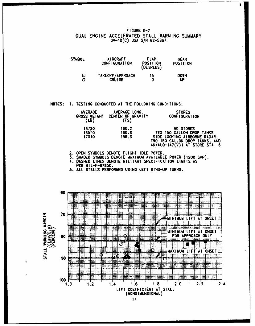
Destroy this report when it is no longer needed. Do not return it to the originator.
TRADE NAMES
The use of trade names in this report does not constitute an official endorsementor approval of the use of the commercial hardware and software.

UNCLASSIFIEDSECRITY CLASSIFICATION OF THIS PAGE
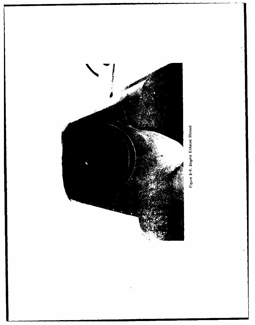
REPORT DOCUMENTATION PAGE FOmApoved0-08
I.REPORT SECURITY CLASSIFICATION l b. RESTRICTIVE MARKINGS
2a. SECURITY CLASSIFICATION AUTHORITY 3. DISTRIBUTION/I AVAILABILITY OF REPORT
2b. DECLASSIFICATION / DOWNGRADING SCHEDULE
4. PERFORMING ORGANIZATION REPORT NUMBER(S) S. MONITORING ORGANIZATION REPORT NUMBER(S)
AEFA PROJECT NO. 87-13
6.. NAME OF PERFORMING ORGANIZATION 6 b. OFFICE SYMBOL 7a. NAME OF MONITORING ORGANIZATIONU.S. ARMY AVIATION ENGINEERINj (if applicable)
Sc. ADDRESS (City, State, and ZIP cod) 7b. ADDRESS (City. State. and ZIP Cod*)
EDWARDS AIR FORCE BASE. CALIFORNIA 93523-5000
fa. NAME OF FUNDING/ISPONSORING Sb. OFFICE SYMBOL 9. PROCUREMENT INSTRUMENT IDENTIFICATION NUMBERORGANIZATION U.S. ARMY(i plcbe
AVIATION SYSTEMS COMMANDBr_ ADDRESS (City, State, and ZIP Co*.) 10. SOURCE Of FUNDING NUMBERS
4300 GOODFELLOW BLVD. ELEMENT NO. NO, NO. ACCESSION NO.ST. LOUIS, MO 63120-1798 [JA060 JE
11. TITLE (Include Security Classification)
Verification of the Production Safe Flight Instrument Corporation OV/RV-ID Stall Warning System. Unclassified.
12. PERSONAL AUTHOR(S)CW4 Joseph C. Miess, Charles Q. Crowell, CW4 Patrick Sullivan
13a. TYPE OF REPORT 113b. TIME COVERED 114. DATE OF REPORT (Yea, Month Day) IS5. PAGE COUNTFINAL I ROM 17/08/88 To 25/08/881 November 1988 44
16. SUPPLEMENTARY NOTATION
17. COSATI CODES 1S. SUBJECT TERMS Continue owi Nees neceuuy and lodfy6 by block nuber)
FIELD GROUP SUB-GROUP Angle of Attack, Configurations, Interchangeability, Louvered Scarfed ShroudSuppressor (LSSS). Prototype, Warning Margin 44
19. ABSTRACT (Continuo on niuese If necessar'y and Identify by block nuniber)ASafe Flight lnstrume~4t Corporation (SFIC) stall warning system androte nomlackration (g) limit aural wtarning
'Jevice were evaluiated 'en an OV-1ID(C) at Edwards Air Force Base, California, from 1 to 25 August 1988.' Fifteen productivetest flight hours wer 4impleted.- The tests were conducted with the Louvered Scarfed Shroud Suppresser (LSSS) not installed
clu toexessve ntne aceleand Tirewall temperatures previously encountered with the YT53-L-704 engines. Interchan-geahility of the SFIC stall warning system between aircraft was demonstrated by the good correlation of data bet%%een (3rum-man's test on airtraft/SN _67-18922 nd U.S. Army Aviation Engineering Flight Activity's (AEFA's) test on aircraft,.62-5867 for LSSS not installed. Additionally;AlGrumman's data shows adequate warning margin for LSSS on. There werel
Ioee, inadequiate stall margins with LSSS not installed for dual-engine unaccelerated stalls, drop tanks only, and no-storeconfigurations. Single engine warning margins were inadequate, especially with the right engine operating near maximum power.Accelerated st~ll warning margins were satisfactory for all wing stores configurations. If the SFIC system is installed on operational aircraf~without LSSS, the SFIC system should be adjusted to provide approximately 3 knots more warning margin for lowpower stalls. The SF[C system should be installed on OV/RV-ID aircraft because of inadequate aerodynamic stall warning.
22a. NAME OF RESPONSIBLE INDIVIDUAL 22b. TELEPHONE (include Arma Code) 22c. OFFICE SYMBOLSHEILA R. LEWIS (805) 277-2115 1SAVTE-PR
OD Form 1473. JUN 86 Provious edtfous a tbaot. SECURITY CLASSIFICTION OF THIS PAIGEUNCLASSIFIED

BLOCK 19 (continued)
However, to enhance pilot operational capabilities a system should be developed that provides continuous angle ofattack information. The g limit aural warning device was evaluated during conduct of accelerated stalls and evasivemaneuvers. The system provides adequate warning for relatively slow increases in g, but is inadequate foraggressive maneuvering above the maneuvering speed. The system was not adjustable for the various g limitsassociated with different wing stores configurations.
mIS GRWI
DTIC TABUnmMouleed E3Justifler - -
DistribUt til
AAva-ilabilit CodesAvaff--/o-W
Dist Sp""Il
/1-I

TABLE OF CONTENTS
PAGE
INTRODUCTION
Background .................................................. ITest Objectives................................................1IDescription .................................................. 1ITest Scope................................................... ITest Methodology ............................................. 2
RESULTS AND DISCUSSION
General ..................................................... 5Dual-Engine Unaccelerated Stall Warning ........................... 5
General ................................................. 5All-Stores ............................................... 6Drop Tank Only.......................................... 6No Stores ...... :......,*..............'*..................6Effect of Side-Slip......................................... 7
Single-Engine Unaccelerated Stall Warning .......................... 7General ................................................. 7All-Stores ............................................... 8Drop Tanks Only.......................................... 8No-Stores ............................................... 8
Dual-Engine Accelerated Stall Warning ............................. 8Acceleration g Limit Warning System.............................. 9Exhaust Shroud Buckling........................................ 9
CONCLUSIONS
General ..................................................... 10Specific ..................................................... 10Shortcomings.................................................1ISpecification Compliance........................................ 10
RECOMMENDATIONS............................................ 12

APPENDIXES
A. References .. . . . . . . . . . . . . . . . . . . . . . . . . . 13B. Aircraft Description.............................................. 14C. Instrumentation................................................. 21D. Test Techniques and Data Analysis Methods .......................... 24E. Test Data ..................................................... 27
DISTRIBUTION

INTRODUCTION
BACKGROUND
i. The Safe Flight Instrument Corporation (SFIC) stall warning system was previouslyevaluated on the OV-1D(C) by the U.S. Army Aviation Engineering Flight Activity(AEFA) (ref 1. 2, and 3, app A). Further development work by SFIC and GrummanAircraft Corporation (GAC) has been completed and verification of the production stallwarning system characteristics was necessary prior to a production decision. The U.S.Army Aviation Systems Command directed AEFA to evaluate the production SFICsystem (ref 4). GAC's flight test report is contained in FTD-134-67.11 (ref 5).
TEST OBJECTIVES
2. The objective of this test was to evaluate the production SFIC stall warning system.An additional objective was to evaluate a prototype normal acceleration (g) limit auralwarning system.
DESCRIPTION
3. The OV-1D(C) Serial Number 62-5867 is a two-place, midwing observation/surveillance aircraft equipped with two YT53-L-704 Lycoming gas turbine engines eachrated at 1800 shaft horsepower at sea level standard day conditions. The test aircraft hadAN/ALQ-136(V)2 wing tip antennae installed and a production SFIC stall warningsystem. The test was conducted without the Louvered Scarfed Shroud Suppresserinstalled due to engine firewall temperature limitations with the YT53-L-704 engines.Other configurations included the side looking airborne radar and the 147(V) 1 infraredcountermeasure pod. A detailed description of the aircraft is contained in appendix B andin the operator's manual (ref 6).
a. The SFIC stall warning system consists of a lift transducer (vane), lift computer,pendulous accelerometer, rudder pedal shaker and stall warning tone generator. The lifttransducer provides an electrical signal to the lift computer which is proportional to the liftcoefficient ratio, CL/CL max. A more detailed description of the SFIC system is includedin appendix B.
b. The g limit aural warning system provides an audible tone through the intercomsystem above pre-determined g levels. As g levels increase above the predeterminedlevels the tone repetition rate of the interrupted tone increases until at the limit g the tonebecomes continuous. A more detailed description of the g alert system is included inappendix B.
TEST SCOPE
4. Testing was conducted at Edwards Air Force Base, California between 17 and25 August 1988. Nineteen flights and 20 flight test hours (15 productive flight hours)were flown. Dual- and single-engine unaccelerated stall and dual engine accelerated stallevaluations were conducted in accordance with the test plan (ref 7), and within the limits
1
of the operator's manual and airworthiness release (ref 8). Tests were conducted in theconfigurations listed in table 1 at the conditions listed in table 2. No adjustments to thewarning system were made during the tests. Stall warning margins were compared to therequirements of MIL-F-8785C (ref 9) and with the data from Grumman's test (ref 5).The stall warning aural tone was compared to MIL Standard 41 ID (ref 10).
TEST METHODOLOGY
5. Established engineering flight test techniques and data reduction procedures wereused during this evaluation (refs 11 and 12). The test methods are briefly described inthe Results and Discussion section of this report. A more detailed description of the testtechniques and data analysis methods may be found in appendix D. Data were handrecorded in the cockpit, on magnetic tape on-board the test aircraft, and via telemetry tothe Real-Time Data Acquisition and Processing System (RDAPS) facility. Telemetrydisplays in the RDAPS facility were used to monitor critical parameters in flight.Appendix C contains listings of the test instrumentation. An airspeed calibration(fig. C-I), and weight and balance check were conducted prior to start of the flight tests.Fuel cell calibration and flight control rigging checks performed during previous stall testswere used for this evaluation. A Handling Qualities Rating Scale (fig. D-1) was used toaugment pilot comments relative to the aircraft handling qualities.
2
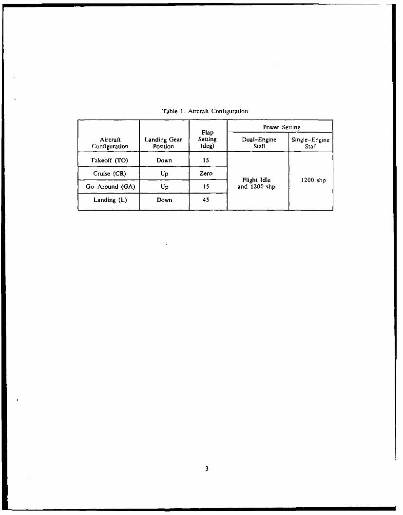
Table I. Aircraft Configuration
Power SettingFlap
Aircraft Landing Gear Setting Dual-Engine Single-EngineConfiguration Position (deg) Stall Stall
Takeoff (TO) Down 15
Cruise (CR) Up ZeroFlight Idle 1200 shp
Go-Around (GA) Up 15 and 1200 shp
Landing (L) Down 45
3

Table 2. Test Conditions2
Takeoff LongitudinalTrim Gross Center of
Airspeed Weight Gravity2 AircraftTest (KIAS) (Ib) (FS) Configuration Store Configuration
15,000 160.3 None
17,200 160.8 Two (2) 150 gallon drop lanksI ngile 1.2 VS 3
SLAR', two (2) 150 gallon drop iank,
18,300 158.9 TO AN/ALQ-147(V)! (store SialionCR
15,000 160.3 GA NoneVnl -~gn "V$5 LSlall YS, 17,200 160.8 Two (2) 150 gallon drop tanks
18,300 158.9 SLAR, two (2) 150 gallon drop lank.,
AN/ALQ- 147(V) 1 (store Stlatim m
15,300 160.3 None
I Imal-Engine 17,200 150.8 Two (2) 150 gallon drop tanksAt CelcralCd 1. 4 v., TOG
Saldl 18,300 158.0 CR' SLAR, two (2) 150 gallon drop tanks.
AN/ALQ-147(V)l (store station oi
MissionManeuvers 160 15,500 157.6 CR SLAR
Nor)FES:
',AI icsts were conducted at approximately 10,000 feet Hp with the AN/ALQ 136(V)2 antenna wing tips installed, and without 11eI ,ov.rcd Scarfed Shroud Suppressor installed.I hc, longitudinal centers of gravity represent normal mission centers of gravity for the configurations noted.
V, : Dual engine power OFF stall airspeed for a specific aircraft configuration. Operator's manual recommended takeoff trim:,iaw. s twd (or the TO aircraft configuration..\R: Side Looking Airborne Radar.IV : Single engine best rate of climb airspeed.i, wurc conducted at 1.7 g..i. wut c',ndllLhd at 2.0 g and 2.5 g.
4
RESULTS AND DISCUSSION
GENERAL
6. The stall warning characteristics of the production Safe Flight Instrument Corporation(SFIC) system were evaluated without the Louvered Scarfed Shroud Suppresser (LSSS)installed in the configurations shown in table I and at the test conditions shown in table 2of the Introduction. The LSSS was not installed because of excessive engine firewall andnacelle area skin temperatures experienced during previous tests (ref 3, app A).Interchangeability of the SFIC system between aircraft was demonstrated by the goodcorrelation between Grumman's test on aircraft serial number 6718922 and the U.S.Army Aviation Engineering Flight Activity's aircraft serial number 62-5867 for LSSS notinstalled. Additionally, Grumman's data shows adequate warning margin for LSSS on.Dual engine stall warning margins with LSSS removed do not meet MIL-F-8785C criteriafor all configurations. Stall warning margins for the drop tanks only and no-storesconfigurations are inadequate in some flight conditions. A warning will be required in thehandbook if the SFIC system is installed on aircraft without LSSS. If the SFIC system isinstalled on operational aircraft without LSSS, the SFIC system should be adjusted toprovide approximately 3 knots more warning margin for low power stalls. Single enginestall warning margins are unsatisfactory and will require a warning in the handbook if theSFIC system is installed. Accelerated stall warning margins met MIL-F-8785C (ref 9)criteria and are satisfactory. System effectiveness is slightly degraded by the high noiseand vibration levels at high rpm/high power settings. The test aircraft, serial number62-5867, exhibits a pedal oscillation in the flaps down configurations with power settingsabove 35 to 40 percent torque (ref I and 2). This oscillation also reduces SFIC systemstall warning effectiveness in the Takeoff (TO), Landing (L), and Go-Around (GA)configurations. The OV-1D(C) stall warning system was evaluated during missionmaneuvers and provided adequate tactile and aural warning of impending stall duringconduct of these maneuvers. Aerodynamic buffet onset provides some warning ofimpending stall in some configurations, but in other combinations of power and flapsettings there is no buffet. Consequently, airframe buffet is not a reliable warning ofimpending stall. The SFIC stall warning system provides some stall warning for allconfigurations even though in some cases the margins are inadequate. The SFIC auralwarning tone did not meet the guidelines of MIL Standard 411D, although it wassatisfactory as an effective artificial stall warning signal. In the absence of adequate stallwarning, the incorporation of any stall warning system is better than none at all. However,to enhance pilot operational capabilities a system that provides continuous angle of attackinformation should be developed.
DUAL-ENGINE UNACCELERATED STALL WARNING
General
7. Dual-engine unaccelerated stall warning margins were evaluated in the aircraftconfigurations shown in table I and at the conditions shown in table 2 of theIntroduction. Stalls were also conducted at 1/2 ball width out of trim, left and righz, todetermine the effect of sideslip on stall warning margins. Flight control trim tabs were setfor each aircraft configuration as defined in appendix D. For most conditions buffet onsetwas followed by artificial stall warning. The stall was defined by an uncommanded
5

pitching, rolling or yawing or some combination of the three. Recovery hon tile stalledcondition was easily effected by relaxation of aft stick pressure. There were insignificantdifferences in SFIC stall warning margins with either left or right sideslip. The SFIC stallwarning margins for drop tanks only and the no-stores configurations were unsatisfactory,did not meet MIL-F-8785C requirements, and are a shortcoming. However, the SFICsystem does provide some warning and therefore a margin of operational safety notavailable without the SFIC system. The following warning should he placed in thehandbook:
WARNING
"The SFIC stall warning system does not provideadequate (5 knots) warning for all combinations ofpower, wingstores and flap settings with LSSS off,therefore, the pilot must take immediate stall preventiveaction at first indication of artificial warning."
All-Stores
8. Artificial stall warning margins for the all-stores dual engine unaccelerated stalls arepresented in figure E-1, appendix E. The SFIC stall warning margins for the dual-engineunaccelerated stalls in the all-stores configuration varied from four and one-half knotscalibrated airspeed (KCAS) at flight idle power to 14 KCAS at maximum power. For theapproach configuration the maximum speed for warning onset allowed by paragraph3.4.2.1.1.1 of MIL-F-8785C was exceeded by nearly two knots, while stall warningmargin was approximately one-half knot less than the required five knots for someconfigurations. The SFIC stall warning system failed to meet MIL-F-8785C requirementsat all conditions, but is satisfactory for the all-stores configuration.
Drop Tanks
9. Artificial stall warning margins for the drop tanks only unaccelerated stalls arepresented in figure E-2. The SFIC stall warning margins for the dual-engineunaccelerated stalls for the drop tanks only configuration varied from 2.8 KCAS in the,anding configuration at flight idle power to 18 KCAS in the landing configuration atmaximum power. The stall warning margins for the drop tanks only configuration dualengine unaccelerated stalls do not meet the requirements of paragraph 3.4.2.1.1.1 ofMIL-F-8785C in that the stall warning margin was two knots less than the five knotsrequired. The stall warning margins for the drop tanks only dual-engine unacceleratedstalls are unsatisfactory. The artificial stall warning margin for the dual engine, drop tanksonly, unaccelerated stalls is a shortcoming. However, the SFIC system provides a marginof stall warning not available without the SFIC system. If the SFIC system is installed, thewarning discussed in paragraph 7 should be plac-d in the handbook.
No-Stores
10. Artificial stall warning margins for the no-stores dual engine unaccelerated stalls arepresented in figure E-3. The SFIC stall warning margins for the dual-engineunaccelerated stalls for the no-stores configurations varied from two KCAS in the cruise
6

configuration at flight idle power to 17 KCAS for the landing configuration at maximumpower. The stall warning margins for the no-stores configuration do not meet therequirements of paragraph 3.4.2.1.1.1 of MIL-F-8785C in that the stall warning marginwas three knots less than the five knots required. The stall warning margins for theno-stores dual-engine unaccelerated stalls are unsatisfactory. The artificial stall warningmargins for the dual engine, no-stores configuration unaccelerated stalls are ashortcoming. However, the SFIC system provides a margin of stall warning not availablewithout the SFIC system. If the SFIC system is installed the warning discussed inparagraph 7 should be incorporated in the handbook.
Effect of Side-Slip
11. Dual engine unaccelerated stalls with sideslip data are presented in figures E-1through E-3. The stalls were conducted with 1/2 ball width out of trim both left and right.This resulted, for some configurations in up to 12 degrees of sideslip at the stall. Therewere insignificant changes in stall warning margin with sideslip, either left or right, for allwing stores configurations.
SINGLE-ENGINE UNACCELERATED STALL WARNING
General
12. The SFIC single-engine unaccelerated stall warning margins were evaluated in theaircraft configurations shown in table I and at the conditions shown in table 2 of theIntroduction. Evaluations were conducted with both left and right engines individuallyshut down and feathered and with the power lever at ground idle with the propeller atmaximum rpm to simulate an uncontrollable propeller. These conditions were evaluatedto determine if there were propeller effects on the stall warning system, since the stallwarning vane is located on the outboard portion of the right wing. The aircraft wasdecelerated at one knot indicated airspeed per second or less, until the stall occurred.The most significant effect (insufficient margin) was with the left engine inoperative(either windmilling or feathered) and the right engine operating at maximum power.There was no significant difference in single-engine warning margins with the leftpropeller windmilling or feathered. Single-engine stall warning margins do not meetMIL-F-8785C criteria and are a shortcoming. The following warning should beincorporated in the handbook if the SFIC system is installed.
WARNING
"The SFIC stall warning system does not provideadequate (5 knots) warning during single-engineoperation. The pilot must take immediate stall preventiveaction at first indication of artificial warning.Additionally, the SFIC system will not give warning ofimpending minimum control speed with the criticalengine inoperative."
7

All-Stores
13. Artificial stall warning margins for the single engine all-stores configuration arepresented in figure E-4. The SFIC stall warning margins for the single-engineunaccelerated stalls for the all-stores configuration varied from approximately one andone-half KCAS in the cruise configuration with the left propeller windmilling and the rightengine at maximum power to 12 KCAS in the cruise configuration with left enginemaximum power, and right propeller windmilling. The SFIC stall warning margins for thesingle-engine all-stores configuration do not meet the requirements of paragraph3.4.2.1.1.1 of MIL-F-8785C in that the stall warning for some conditions was only oneand one-half knots. The artificial warning for the all-stores single engine configuration isunsatisfactory and is a shortcoming. However, the SFIC system provides a margin of stallwarning not available without the system. The warning discussed in paragraph 12 shouldbe incorporated in the handbook if the SFIC system is installed.
Drop Tanks Only
14. Artificial stall warning margins for the single engine, drop tanks only configurationare presented in figure E-5. The SFIC stall warning margins for the single-engineunaccelerated stalls for the drop tanks only configuration varied from approximately3 KCAS for the GA configuration (right engine at maximum power, left propellerwindmilling) to 9 KCAS for the Cruise (CR) configuration (left engine at maximum powerand right propeller windmilling). The stall warning margins for the single-engine droptanks only configuration did not meet the requirements of paragraph 3.4.2.1.1.1 ofMIL-F-8785C in that the minimum warning margin was 2 knots less than the 5 knotsrequired. The artificial warning margin for the drop tanks only single engine configurationis unsatisfactory and is a shortcoming. However, the SFIC system provides a margin ofstall warning not available without the system. The warning discussed in paragraph 12should be incorporated in the operator's manual if the SFIC system is installed.
No Stores
15. Artificial stall warning margins for the single engine no-stores configuration arepresented in figure E-6. The SFIC stall warning margins for the single-engineunaccelerated stalls for the drop tank only configuration varied from two KCAS in theGA configuration (right engine at maximum power, left engine propeller feathered) toapproximately 12 KCAS in the GA configuration (left engine at maximum power andright propeller windmilling). The stall warning margins for the single-engine no storesconfiguration do not meet the requirements of paragraph 3.4.2.1.1.1 of MIL-F-8785C inthat the stall warning margin was 3 knots less than the 5 knots required. Theunsatisfactory warning margins are a shortcoming. However, the SFIC system provides amargin of stall warning not available without the system. If the SFIC system is installed thewarning discussed in paragraph 12 should be incorporated in the handbook.
DUAL-ENGINE ACCELERATED STALL WARNING
16. Dual-engine accelerated stall warning margins were evaluated in the aircraftconfigurations shown in table 1, at the conditions in table 2 of the Introduction. Most of
8

the dual-engine accelerated stalls were performed using left wind-up turns since post stallgyrations from accelerated stalls typically result in a right roll. Normal accelerations at stallvaried from 1.7 to 2.5 g's.
17. A summary of dual engine accelerated stall warning margin is presented infigure E-7. Stall warning margin is presented in percent of coefficient of lift at stall.During performance of mission evasive maneuvers, the pilot could maneuver the aircraftto limit g (with the g warning system providing adequate warning) or to just below stall(with adequate warning provided by the stall warning system). The aircraft was easilyprevented from stalling by reducing the severity of the maneuver (HORS 2). Thedual-engine accelerated stall warning margins for all configurations meet the requirementsof MIL-F-8785C and are satisfactory.
18. Mil Standard 41 ID (ref 10) requires a stall aural warning tone to be an interrupted400 Hertz (Hz) signal varying from one cycle per second at activation to ten cycles persecond at the point of stall. The SFIC aural warning tone did not meet the guidelines ofMil Standard 411D although it was satisfactory as an effective artificial stall warningsignal.
ACCELERATION g LIMIT AURAL WARNING SYSTEM
19. A prototype normal acceleration g limit warning system was installed andqualitatively evaluated during this stall warning test. The pilot could select either a singleor dual interrupted tone. The g alert onset could be pilot selected at 2.5 or 3 g. The dualinterrupted tone was preferred as it was more readily distinguishable from the stallwarning tone. The pilots preferred to have alert onset adjusted at the 3g level to avoidnumerous nuisance alerts. The g alert warning system provided adequate warning forrelatively slow, smooth increases to the g limit, but did not provide adequate warningduring aggressive maneuvering above the maneuvering speed. The inadequate warning ofimpending limit g during aggressive maneuvering is a shortcoming. The 400 Hz tone wassatisfactory by itself, but became difficult to differentiate from the stall warning when bothwere activated. The warning system tone should be evaluated in conjunction with afull-up Aircraft Survivability Equipment suite and stall warning system to determine if theproliferation of tones results in auditory saturation. A voice synthesis stall and g alertwarning system should be evaluated. The g alert system should have an adjustable g limitfor different load configurations.
EXHAUST SHROUD BUCKLING
20. The left engine exhaust shroud became buckled and warped, apparently due toexhaust temperatures encountered during low speed, high powered flight. A picture of thedistorted shroud is shown in figure E-9. This distortion indicates that a potential exhaustshroud overtemperature condition exists with T53-L-704 engine operation. Theinstrumented right engine firewall temperatures did not approach AVSCOM providedlimit temperatures (315 degrees Centigrade). The exhaust shroud (non-LSSS) should beevaluated at YT53-L-704 operational temperatures at low speeds and high power todetermine if the temperatures will cause shroud life reduction.
9

CONCLUSIONS
GENERAL
21. The Safe Flight Instrument Corporation (SFIC) stall warning system providedunsatisfactory warning for some stores configurations and flight conditions, however, thesystem provides a margin of safety not available without the system installed.
22. Interchangeability of the SFIC system was demonstrated by the good correlation ofdata between Grumman's test on aircraft serial number 67-18922 and the U.S. ArmyAviation Engineering Flight Activity's aircraft serial number 62-5867 for LSSS notinstalled.
SPECIFIC
23. The SFIC stall warning margins are satisfactory for the dual engine all storesconfiguration (para 8).
24. The SFIC stall warning margins for dual engine accelerated stalls (all configurations)are satisfactory (para 16).
25. There were insignificant changes in stall warning margin with side slip, either left orright, for all wing stores configurations (para 11).
26. The g alert system provided adequate warning for relatively slow, smooth increasesto the g limit, but did not provide adequate warning during aggressive maneuvering(para 19).
27. The left engine exhaust shroud buckled and warped, apparently due to exhausttemperatures encountered during low speed, high power stalls (para 20).
SHORTCOMINGS
28. The following shortcomings were identified and are listed in decreasing order ofrelative importance.
a. The inadequate stall warning margins for dual engine unaccelerated stalls for theLouvered Scarfed Shroud Suppressor (LSSS) off, drop tanks only and no-stores
configurations (para 9 and 10).
b. The inadequate stall warning margins for single engine operation in all wing storesconfigurations (para 12, 13, and 14).
c. The inadequate warning of impending limit g during aggressive maneuveringprovided by the g alert system (para 19).
SPECIFICATION COMPLIANCE
29. The SFIC stall warning system failed to meet the following requirements ofMIL-F-8785C:
to
a. Paragraph 3.4.2.1.1.1 in that the SFIC warning margins for the dual engineunaccelerated stalls, LSSS off, drop tanks only and the no-stores configuration arethree knots less than required (paras 9 and 10).
b. Paragraph 3.4.2.1.1.1 in that the SFIC stall warning margins for single engineoperation in all configurations were three knots less than required (para 12, 13, and 14).
30. The SFIC aural warning system failed to meet the following requirements of MILSTD 411D in that the aural stall warning tone was not an interrupted 400 Hertz audiosignal varying from one cycle per second at activation to ten cycles per second at the pointof stall (para 18).
11

RECOMMENDATIONS
31. Install the Safe Flight Instrument Corporation Stall Warning System (SFIC) (paras7, 8, 9, 10. 12, 13. 14, 15 and 16.
32. If the SFIC system is installed on operational aircraft without Louvered ScarfedShroud Suppressor (LSSS), the SFIC system should be adjusted to provide approximatelythree knots more warning margin for low power stalls (para 6).
33. A system that provides continuous angle of attack information should be developed(para 6).
34. The following warning should be placed in the handbook (para 7):
WARNING
"The SFIC system does not provide adequate stallwarning for all combinations of power, wing stores, andflap settings with LSSS off, therefore, the pilot must takeimmediate stall preventive action at first indication ofartificial warning."
35. The following warning should be incorporated in the handbook if the SFIC system isinstalled (para 12):
WARNING
"The SFIC stall warning system does not provideadequate (5 knots) warning during single engineoperation. The pilot must take immediate stall preventiveaction at first indication of artificial stall warning.Additionally, the SFIC system will not give warning ofimpending minimum control speed with the criticalengine inoperative."
36. The warning system tone should be evaluated in conjunction with a full up AircraftSurvivability suite and stall warning system to determine if the proliferation of tonesresults in auditory saturation (para 19).
37. The g alert system should have an adjustable g limit for different load configurations(para 19).
38. A voice synthesis system should be evaluated for the stall warning and g alert systems(para 19).
39. The exhaust shroud (non-LSSS) should be evaluated at YT53-L-704 operationaltemperatures at low speeds and high power to determine if the temperatures will reduceshroud life (para 20).
12

APPENDIX A. REFERENCES
I. Final Report, AEFA Project No. 84-13, Evaluation of the OV-ID Stall WarningCharacteristics, January 1986.
2. Final Report, AEFA Project No. 85-16, Evaluation of the Safe Flight InstrumCntCorporation Stall Warning System for the OV-ID Aircraft, February 1986.
3. Final Report, AEFA Project No. 85-17-1, Flaps-up Takeoff Performance of theOV-ID with YT53-L-704 Engines Installed, May 1987.
4. Letter, AVSCOM, AMSAV-8, 22 June 1987, subject: Verification of the ProductionSafe Flight Instrument Corporation Stall Warning System (test request).
5. FTD-134-67.11, Evaluation of The Safe Flight Instrument Corporation StallWarning System in OVIRV-) Mohawk Aircraft, 10 June 1987.
6. Technical Manual, TM 55-1510-213-10, Operator's Manual, OV-ID/RV-IDAircraft, 4 August 1978.
7. Letter, AEFA, SAVTE-TA, 26 September 1985, subject: Revision 1, Test Plan,Evaluation of the Safe Flight Instrument Corporation Stall Warning System for theOV-ID/RV-1D Aircraft, AEFA Project No. 85-16.
8. Letter, AVSCOM, AMSAV-E, 10 May 1988, subject: Airworthiness Release,()V- I D, SN 62-5867, Verification of the Production Safe Flight Instrument CorporationOV-ID/RV-1D Stall Warning System.
9. Military Specification, MIL-F-8785C, Flying Qualities of Piloted Airplanes,5 November 1980.
10. Military Standard, MIL Standard 411D, Aircrew Station Signals, 30 June 1970.
1I. Flight Test Manual, Naval Air Test Center, FTM No. 104, Fixed Wing Performance,
July 1977.
12. Flight Test Manual, Naval Air Test Center, FTM No. 103, Fixed Wing Stability andControl, 1 January 1975.
13. Flight Test Report, Flaps-up Takeoff Performance of the OV-ID aircraft withYT43-L-704 Engines Installed, Project No. 85-17-1, May 1987.
14. Pilot's Guide, Safe Flight Instrument Corporation, R-2145, Prestall WarningSystem, Grumman OV-1D/RV-1D (Mohawk), 20 August 1985.
15. Grumman Aircraft Corporation Technical Bulletin 134-ST-TB-85, Installation (if'rototype Acceleration Limit Warning System OV-ID(C) Aircraft.
13

APPENDIX B. DESCRIPTION
DESCRIPTION
I. The OV-ID(C) test aircraft, serial number 62-5867 (figs. B-I and 2) is a two-place,twin engine turboprop aircraft featuring a mid-wing, triple vertical stabilizers, and tricyclelanding gear. Seven external store stations, (one on the fuselage, six on the wings) areused to carry a variety of surveillance pods and/or fuel tanks. For this program, theaircraft was tested in three wing stores configurations: no stores, two 150 gallon droptanks installed (drop tanks only configuration); and with two 150 gallon drop tanks,AN/ALQ-147A(V) 1, with the Side Looking Airborne Radar (SLAR) boom installed (theALL-STORES configuration). The Louvered Scarfed Shroud Suppresser (LSSS) was notinstalled. The AN/ALQ-136(V)2 wing tip antennas (fig. B-3) and a production SafeFlight Instrument Corporation (SFIC) stall warning system was installed. A more detaileddescription of the basic OV-I aircraft is contained in the operator's manual (ref 6,app A).
2. The production (SFIC) stall warning system consisted of the following components: alift transducer, lift computer, pendulous accelerometer, rudder pedal shaker, and stallwarning tone generator. The lift transducer is an electromechanical device consisting of amovable vane and mounting plate which incorporates integral anti-icing heaters. Theanti-icing heaters are activated through the aircraft pitot heat switch. The lift transducerwas mounted on the right wing (fig. B-3). The spanwise location of the center of the lifttransducer vane was at right wing station 274.0. The chordwise location of the center ofthe lift transducer vane was on the lower surface of the wing leading edge 5.375 inchesforward of the forward edge of the skin line on the bottom of the wing (where the wingskin and deice boot join). This corresponds to 6.531 inches forward of the forward edgeof the skin line on the top of the wing (where the wing skin and deice boot join). Thesedimensions were measured along the surface of the wing deice boot. During flight, thevane position is determined by airflow stagnation point location on the wing and is afunction of local airflow which varies with changes in angle of attack of the wing. The lifttransducer provides an electrical signal to the lift computer which is proportional to the liftcoefficient ratio, CL/CLmax. The flap position transmitter is an electro-mechanicaldevice which supplies flap position information to the lift computer. The flap positiontransmitter is connected to the flap system and automatically supplies flap positioninformation to the lift computer to compensate for the effect of flap position on liftcoefficient. A landing gear switch automatically disables artificial stall warning andsupplies low heat to the anti-icing heaters of the lift transducer when the aircraft pitotheat switch is ON, and the aircraft is on the ground. The pendulous accelerometertransmits a signal to the lift computer as a function of variation of aircraft pitch attitude,normal acceleration and longitudinal acceleration. The stall warning activation schedule ispresented in figure B-4. A block diagram of the stall warning system is shown infigure B-5. The lift transducer, flap position transmitter and pendulous accelerometersupply signals to the lift computer which activates the rudder shaker and audio tone at apredetermined margin prior to the aircraft reaching an aerodynamic stall. The rudderpedal shaker was mounted on the pilot's left rudder pedal. A 400 Hertz audio tone at +12decibel milliwatts activates simultaneously with the rudder shaker to provide an aural stallwarning signal to the intercom system. The tone volume can be neither decreased nordisabled by the flight crew. The stall warning system incorporates a self-test switch which
14

allows the pilot to check the system on the ground or in flight. When the aircraft is on tileground, a solenoid in the lift transducer actuates to push the vane forward and simulate astall condition activating the rudder shaker and stall warning tone. Actuiting the self-testswitch in flight introduces an electrical test signal simulating forward movement of the lifttransducer vane causing rudder shaker and stall warning tone activation. A more detaileddescription of the SFIC stall warning system can be found in the SFIC Pre-Stall WarningSystem Pilot's Guide (ref 14).
3. The g limit aural warning system is intended to improve pilot awareness of aircraftfatigue stress levels by providing an audible tone through the intercommunications systemabove pre-determined g levels. For this test, a cockpit control unit was provided whichallowed selection of warning initiation at the 2 1/2 or 3 g level. The test pilot could selectsingle or dual interrupted tone, and adjust tone volume. As g levels increased above theselected initiation level the repetition rate of the interrupted tone increased until at 4 g thetone became continuous. A self test switch activated the tone to verify that the system wasoperational. The g alert system was installed in accordance with Grumman TechnicalBulletin, TB 134-ST-TB-85, 21 August 1987 (ref 15).
15

~/
e -
,4,
\0
16~
• • i I 4

II
kL
...
17.

II,~ I
I
,. / ~iU
0U"
F* A
j
0
U
I8

UU
I =
I.
U) co
4o C4aCI I
0 IWWNLVLO VSVE lLNOV
I')I 38O
I19

zW
im
WMS
I LI-
w*A
6- z
- lbo
20E
APPENDIX C. INSTRUMENTATION
1. 1 I Ill iln latollo Iol this evailuationl wats L'alillvdl't illsnllfllt't ;li0 Iaillilllittl b~y dhw USI
Army Aviation Engineering Flight Activity personnel. Flight test data were recorded o lmagnetic tape onboard the test aircraft and via telemetry to the Real-Time DataAcquisition and Processing System facility. An instrumented boom was installed toprovide pitot and static pressure, side-slip, and angle of attack data. The boom system
airspeed calibration is shown in figure C-1.
2. The following test instrumentation was used in addition to the standard aircraftinstruments:
Cockpit Panel
Engine fuel flow (left and right)Engine fuel totalizer (left and right)Airspeed (ship and boom)Altitude (ship and boom)Ambient air temperatureAngle of attack (boom system)Angle of sideslip (boom system)Normal acceleration (cg)Time code
Magnetic Tape
Airspeed (ship and boom)Pressure Altitude (ship and boom)Total air temperatureLongitudinal control positionLateral control positionDirectional control positionSafe Flight Instrument Corporation (SFIC) lift transducer (volts)SFIC pendulous accelerometer outputAngle of attack (boom system)Angle of sideslip (boom system)Pitch attitudeRoll attitudeI la;dingPitch rate
Roll raleYaw rateCenter of gravity normal accelerationPilot's directional pedal force (left and right)Exhaust gas temperature (left and right)Fuel flow (left and right)Fuel totalizers (left and right)Propeller speed (left and right)Gas generator speed (left and right)Engine torque (left and right)
21

Throttle position (left and right)Left outboard aileron positionRight rudder positionCenter rudder positionTime
22
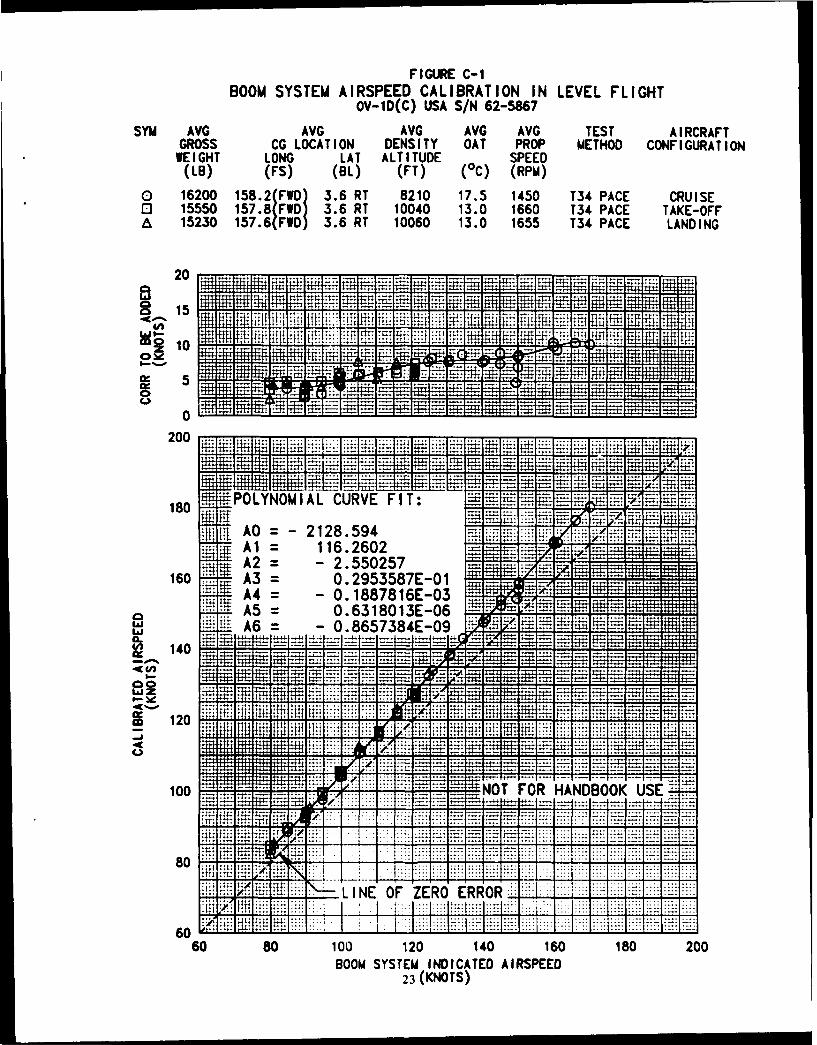
FIGURE C-1BOOM SYSTEM AIRSPEED CALIBRATION IN LEVEL FLIGHT
OV-10(C) USA S/N 62-5867SYM AVG AVG AVG AVG AVG TEST AIRCRAFT
GROSS CG LOCATION DENSITY OAT PROP METHOD CONFI GURA TIONWEIGHT LONG LAT ALTITUDE SPEED(LB) (FS) (81) (FT) (0C) (RPM)
a 120 182FWD) 3.6 RT 8210 17.5 1450 T34 PACE CRUISEo 15550 1578FD 3.6 RT 10040 13.0 1660 T34 PACE TAKE-OFFA 15230 157.6(FWD) 3.6 RT 10060 13.0 1655 T34 PACE LANDING
20
180[ POYIAL CURV FIT 4
16 A3 I P.2915;8UE-O1i 151 f....-U
0
140
A0 =t -- 18.9
100H
60 = -2.50 7
60 80 1002558 O 12 1496 8 0AOOM SYST781E NCTD0ISPEair~2 (KNOTS)ft

APPENDIX D. TEST TECHNIQUES AND DATA ANALYSIS METHODS
TEST TECIINIQUES
1. Unaccelerated stalls were initiated from trimmed level flight at 1.2 times thepower-off stall speed (Vs,) for dual-engine unaccelerated stalls in the cruise, go-aroundand landing configuration and at single-engine best rate of climb speed for single-enginestalls. In the takeoff configuration operator's manual recommended trim settings wereused. The unaccelerated stalls were performed wings-level at an airspeed reduction rateof one knot per second or less. Accelerated stalls were conducted by trimming the aircraftat 1.4 Vsl. The accelerated stalls were performed at a constant g while decreasing theairspeed at approximately 2 knots per second in left windup turns. Aircraft stall wasidentified from the time history data as the point of maximum lift coefficient. Calibratedstall airspeed was defined as the boom calibrated airspeed at stall. A Handling QualitiesRating Scale was used to augment pilot comments relative to the aircraft handling qualities(fig D-1).
DATA ANALYSIS METIIOD
Airspeed Determination
2. Instrument corrected airspeeds (Vic) using the Pulse Code Modulation (PCM) systemwere obtained through the equation:
Vic =ao I 5 [(QiC /Po+ 1)2/7 1 1/2
where:
ao - Standard day, sea level speed of sound, knots
Po = Standard day, sea level static pressure, in-HgQic = instrument corrected differential pressure, in-Hg
3. Boom calibrated airspeeds (Vcal) were obtained by correcting Vic for position error(AVpc).
4. l-quivalent airspeeds (Ve) were obtained through the equation:
V, =ao 1 56 1(Qc/Pc+ 1) 2/7 1J I/ 2
where:
6 = Pc/Po
Pc = Ambient test static pressure, in-Hg
Qc Calibrated differential pressure, in-Hg
Poj 10.2 Vcal/ao] 2 + 11 7/2_ 11
24

Coefficient of Lift Determination
5. Test lift coefficients were obtained through the equation:
CL = (2) (W) (n)eo((Ve) (1.6878))2360
where:
W = aircraft gross weightn = normal load factor
Qo = standard day, sea level density, slugs/ft3
360 = wing surface area, ft2
AIRSPEED CALIBRATION
6. The test boom pitot-static system was calibrated using the aircraft pace method to
determine the airspeed position error and is presented in figure C-2.
WEIGHT AND BALANCE
7. Prior to flight testing, a weight and balance determination was conducted on the
aircraft using calibrated floor scales located under the aircraft landing gear. The aircraftbasic weight and center of gravity with the safe flight stall warning system, side lookingairborne radar, two drop tanks, and airspeed boom and yaps head was 13,337 poundsand fuselage station 160.66.
25

,~0
- j 1,- 1- 7' ~ ( 0 0
0 . CT .-' C:
0 0 Z a30
OCJ) --- -
Wa -z c
a' 0c
LY M- z -z0
0 0 a.0 40 -- 4 i0
X- <- z o y S ,- I c
C) (I z 0 ),Cx 0Ca )L
e cc-. V. 2 r>c
U.' & <.. 5 = ' a
~ z z ZZ0-C w- U)U .4 Uj Gb
6. L)u L" - c
U C-,wC
LU >
_j -L
ui26

APPENDIX E. TEST DATA
Figure Figure Number
Index
Dual-Engine Unaccelerated Stall Warning Summary E-1 through E-3Single-Engine Unaccelerated Stall Warning Summary E-4 through E-6Dual-Engine Accelerated Stall Warning Summary E-7Ship System Airspeed Calibration E-8
Photo
Exhaust Shroud E-9
27

FIGURE E-1
DUAL ENGINE UNACCELERATED STALL WARNING SUMMARYOV-1D(C) USA S/N 62-5867
SYMBOL AIRCRAFT FLAP GEARCONFIGURATION POSITION POSITION
(DEGREES)
O TAKEOFF/APPROACH 15 DOWN0 CRUISE 0 UP
GO-AROUND 15 UPLANDING 45 DOWN
NOTES: 1. EXTERNAL STORES CONFIGURATION: SIDE LOOKING AIRBORNERADAR, TWO 150 GALLON DROP TANKS, AND AN/ALQ-147(V)1.
2. AVERAGE GROSS WEIGHT = 17,320 POUNDS.3. AVERAGE LONGITUDINAL CENTER OF GRAVITY = FS 158.5.4. OPEN SYMBOLS DENOTE BALL CENTERED CONDITION.5. SHADED LEFT SYMBOLS DENOTE ONE-HALF BALL LEFT CONDITION.6. SHADED RIGHT SYMBOLS DENOTE ONE-HALF BALL RIGHT CONDITION.7. UNFLAGGED SYMBOLS DENOTE FLIGHT IDLE POWER.8. FLAGGED SYMBOLS DENOTE MAXIMUM AVAILABLE POWER (1200 SHP).9. DASHED LINES DENOTE MILITARY SPECIFICATION LIMITS AS
PER MIL-F-8785C.
16 'MAXIM SPEED FOR ONSET
z iMAX IMUM SPEED FOR ONSET
z FOR APPROACH ONLY. .. ..
4 MINIMUM SPEED FOR ONSET.
50 60 f0 so 90 100 110
AIRSPEED AT STALL (KCAS)
28

I
FIGURE E-2DUAL ENGINE UNACCELERATED STALL WARNING SUMMARY
OV-iD(C) USA S/N 62-5867
SYMBOL AIRCRAFT FLAP GEARCONFIGURATION POSITION POSITION
(DEGREES)
o TAKEOFF/APPROACH 15 DOWN0 CRUISE 0 UP
GO-AROUND 15 UP0 LANDING 45 DOWN
NOTES: 1. EXTERNAL STORES CONFIGURATION: TWO 150 GALLON DROP TANKS2. AVERAGE GROSS WEIGHT = 15,780 POUNDS.3. AVERAGE LONGITUDINAL CENTER OF GRAVITY = FS 160.3.4. OPEN SYMBOLS DENOTE BALL CENTERED CONDITION.5. SHADED LEFT SYMBOLS DENOTE ONE-HALF BALL LEFT CONDITION.6. SHADED RIGHT SYMBOLS DENOTE ONE-HALF BALL RIGHT CONDITION.7. UNFLAGGED SYMBOLS DENOTE FLIGHT IDLE POWER.8. FLAGGED SYMBOLS DENOTE MAXIMUM AVAILABLE POWER (1200 SHP).9. DASHED LINES DENOTE MILITARY SPECIFICATION LIMITS AS
PER MIL-F-8785C.
20 ....~ ~ ~ ~ ~ ~ ~ ~ ~.. ... ... .. ... .. ... ll........ ....1.....
.... .... .... .....
16 .. .... .... .... !.......
..... . ... ........4....' .... ....
56070 80 90 100 110AIRSPEED AT STALL (KCAS)
29
,j ,. pmI::*' ,.. .. ,. I ....

F I GURE E-3DUAL ENGINE UNACCELERATED STALL WARNING SUMMARY
OV-1D(C) USA S/N 62-5867
SYMBOL AIRCRAFT FLAP GEARCONF I GURAT ION POSITION POSITION
(DEGREES)
0l TAKEOFF/APPROACH 15 DOWN0 CRUISE 0 UP
GO-AROUND 15 UPLANDING 45 DOWN
NOTES: 1. EXTERNAL STORES CONFIGURATION: NO EXTERNAL STORES2. AVERAGE GROSS WEIGHT = 13,080 POUNDS.3. AVERAGE LONGITUDINAL CENTER OF GRAVITY = FS 160.2.4. OPEN SYMBOLS DENOTE BALL CENTERED CONDITION.5. SHADED LEFT SYMBOLS DENOTE ONE-HALF BALL LEFT CONDITION.6. SHADED RIGHT SYMBOLS DENOTE ONE-HALF BALL RIGHT CONDITION.7. UNFLAGGED SYMBOLS DENOTE FLIGHT IDLE POWER.8. FLAGGED SYMBOLS DENOTE MAXIMUM AVAILABLE POWER (1200 SHP).9. DASHED LINES DENOTE MILITARY SPECIFICATION LIMITS AS
PER MIL-F-8785C.
20, -.....
12 .MAXIMUM SPEED FOR ONSET
-- a
AIRSPEED AT STALL (KCAS)30
ig - g g gI

FIGURE E-4SINGLE ENGINE UNACCELERATED STALL WARNING SUMMARY
OV-1D(C) USA S/N 62-5867
SYMBOL AIRCRAFT FLAP GEARCONFIGURATION POSITION POSITION
(DEGREES)
0 TAKEOFF/APPROACH 15 DOWN0 CRU ISE 0 UP
GO-AROUND 15 UPLANDING 45 DOWN
NOTES: 1. EXTERNAL STORES CONFIGURATION: SIDE LOOKING AIRBORNERADAR, TWO 150 GALLON DROP TANKS, AND AN/ALQ-147(V)1.
2. AVERAGE GROSS WEIGHT = 17,070 POUNDS.3. AVERAGE LONGITUDINAL CENTER OF GRAVITY = FS 158.3.4. OPEN SYMBOLS DENOTE NUMBER ONE ENGINE AT MAXIMUM
AVAILABLE POWER (1200 SHP'N5. SHADED SYMBOLS DENOTE NUMBER TWO ENGINE AT MAXIMUM
AVAILABLE POWER (1200 SHP).6. UNFLAGGED SYMBOLS DENOTE INOPERATIVE ENGINE AT GROUND
IDLE AND PROPELLER WINDMILLING.7. FLAGGED SYMBOLS DENOTE INOPERATIVE ENGINE SHUTDOWN
AND PROPELLER FEATHERED.8. DASHED LINES DENOTE MILITARY SPECIFICATION LIMITS AS
PER MI L-F-8785C.
zz3 16 MAXIMUM SPEED FOR ONSET
k
-J
12 MINIMUM SPEED FOR ONSET .
I FOR APRAH NYZ
..... .. .....
-- ,_,J -. .. , .- . . .... .. . .. . .
50 60 70 80 90 100 110AIRSPEED AT STALL (KCAS)
31

F I GURE E-5SINGLE ENGINE UNACCELERATED STALL WARNING SUMMARY
OV-1D(C) USA S/N 62-5867
SYMBOL AIRCRAFT FLAP GEARCONFIGURATION POSITION POSITION
(DEGREES)
O TAKEOFF/APPROACH 15 DOWN0 CRUISE 0 UPA GO-AROUND 15 UP
LANDING 45 DOWN
NOTES: 1. EXTERNAL STORES CONFIGURATION: TWO 150 GALLON DROP TANKS.2. AVERAGE GROSS WEIGHT = 16,470 POUNDS.3. AVERAGE LONGITUDINAL CENTER OF GRAVITY = FS 160.6.4. OPEN SYMBOLS DENOTE NUMBER ONE ENGINE AT MAXIMUM
AVAILABLE POWER (1200 SHP)5. SHADED SYMBOLS DENOTE NUMBER TWO ENGINE AT MAXIMUM
AVAILABLE POWER (1200 SHP).6. UNFLAGGED SYMBOLS DENOTE INOPERATIVE ENGINE AT GROUND
IDLE AND PROPELLER WINOMILLING.7. FLAGGED SYMBOLS DENOTE INOPERATIVE ENGINE SHUTDOWN
AND PROPELLER FEATHERED.S. DASHED LINES DENOTE MILITARY SPECIFICATION LIMITS AS
PER MIL-F-8785C.
20
1!t WAXIMUM SPEED FOR ONSET.._
12 MAXIMUM SPEED FOR ONSET ..... ..........FOR APROAH NLY ::....... ....... .........12
M I NIMUM SPEED FOR ONSET •
... . ......... ... . ... ... ... ... .... .=
.2 fft,.j ; t
0 -
50 60 70 80 90 100 110AIRSPEED AT STALL (KCAS)
32

FIGURE E-6SINGLE ENGINE UNACCELERATED STALL WARNING SUMMARY
OV-1D(C) USA S/N 62-5867
SYMBOL AIRCRAFT FLAP GEARCONFIGURATION POSITION POSITION
(DEGREES)
o TAKEOFF/APPROACH 15 DOWN0 CRUISE 0 UP
GO-AROUND 15 UPLANDING 45 DOWN
NOTES: 1. EXTERNAL STORES CONFIGURATION: NO EXTERNAL STORES.2. AVERAGE GROSS WEIGHT = 13,990 POUNDS.3. AVERAGE LONGITUDINAL CENTER OF GRAVITY = FS 160.1.4. OPEN SYMBOLS DENOTE NUMBER ONE ENGINE AT MAXIMUM
AVAILABLE POWER (1200 SHP)5. SHADED SYMBOLS DENOTE NUMBER TWO ENGINE AT MAXIMUM
AVAILABLE POWER (1200 SHP).6. UNFLAGGED SYMBOLS DENOTE INOPERATIVE ENGINE AT GROUND
IDLE AND PROPELLER WINDMILLING.7. FLAGGED SYMBOLS DENOTE INOPERATIVE ENGINE SHUTDOWN
AND PROPELLER FEATHERED.8. DASHED LINES DENOTE MILITARY SPECIFICATION LIMITS AS
PER MIL-F-8785C.
20 -=::- r
8 H.- _=
MAXIMUM SPEED FOR ONSET
Hi iiili _ MAXIMUM SPEED FOR ONSET.
4 .: . .' ... ..
i~i! : i:.. . . .....
.. .. .. .. .. ... -.
50 60 70 80 90 100 110AIRSPEED AT STALL (KCAS)
33
F I GURE E-7DUAL ENGINE ACCELERATED STALL WARNING SUMMARY
OV-ID(C) USA S/N 62-5867
SYMBOL AIRCRAFT FLAP GEARCONFIGURATION POSITION POSITION
(DEGREES)
o TAKEOFF/APPROACH 15 DOWN0 CRU ISE 0 UP
NOTES: 1. TESTING CONDUCTED AT THE FOLLOWING CONDITIONS:
AVERAGE AVERAGE LONG. STORESGROSS WEIGHT CENTER OF GRAVITY CONFIGURATION
(L) (FS)
13720 160.2 NO STORES16570 160.6 TWO 150 GALLON DROP TANKS17010 158.3 SIDE LOOKING AIRBORNE RADAR,
TWO 150 GALLON DROP TANKS, ANDAN/ALQ-147(V)1 AT STORE STA. 6
2. OPEN SYMBOLS DENOTE FLIGHT IDLE POWER.3. SHADED SYMBOLS DENOTE MAXIMUM AVAILABLE POWER (1200 SHP),.4. DASHED LINES DENOTE MILITARY SPECIFICATION LIMITS AS
PER MtIL-F-8785C.5. ALL STALLS PERFORMED USING LEFT WIND-UP TURNS.
-7 0..
.. ....
.. .. .. . .... ... ...... . .o
.. ..... .... .... .. -MINIMUM LIFT AT ONSETL:• ~ ~ ~ ~ ~ ~ ~ u , ..:':.. il:,. .l, . ... .. ... ........
LIFT .... -- MINIMUM LIFT AT ONSET
; : ;: , : ; , .; ; ; : .. ; ; ; , ; : : , ;: ; ; ;; . . . . ... .... .... .... .. . . . .I . . .I . . . . l t . . . . . l
... ... , .... ... . .... ... . .... : : . ;; : : ;::31 ... .:: .. . .......... ..... .. ....."+-:'. ......... .. ..... .. ........... ..... .... _ _:=::' - MAXIMUM LIFT AT ONSET L
80~ ~ ~ ~ ~ ~ ~ ~ ~ ~ ~ ~. ....t ...... .............-.............. ..4A s oo ... ... . . ... | . . , ., , . . , . , +
... .... ........ . .........
(NONDIMENSIONAL)34

F IGURE E-8SHIP SYSTEM AIRSPEED CALIBRATION IN LEVEL FLIGHT
OV-1D USA S/N 62-05867SYM AVG AVG AVG AVG AVG TEST AIRCRAFT
GROSS CG LOCATION DENSITY OAT PROP METHOD COWFI GURAT IONWEIGHT LONG LAT ALTITUDE SPEED(16) (F'S) (BL) (FT) (0C) (RPM)
0 16200 182 (FWD) 3.6 RT 8210 17.5 1450 T34 PACE CRUISEo 15550 157. (F'ID) 3.6 RT 10040 13.0 1660 T34 PACE TAKE-OFF& 15230 157.6(FWD) 3.6 RT 10060 13.0 1655 T,34 PACE LANDING
10 ... .. ..
o 5
-10 31
200
180 AO = -35.0204
10 A3 0 .1262186E-04...
La
140
S 120
100
80
6060 80 100 120 140 160 180 200
SHIP SYSTEM IDICATED AIRSPEED(KNOTS)
35
fa
00
LLI

DISTRIBUTION
HQDA (DALO-AV) I
I I)A (l)AIO-IDO) I
H1QDA (DAMO-HRS) I
HQDA (SARD-PPM-T) 1
HQDA (SARD-RA) I
HiQDA (SARD-WSA) I
US Army Material Command (AMCDE-SA, AMCDE-P, AMCQA-SA, 4
AMCQA-ST)
US Training and Doctrine Command (ATCD-T, ATCD-B) 2
US Army Aviation Systems Command (AMSAV-8, AMSAV-Q, 8
AMSAV-MC, AMSAV-ME, AMSAV-L, AMSAV-N, AMSAV-GTD)
US Army Test and Evaluation Command (AMSTE-TE-V, AMSTE-TE-O) 2
US Army Logistics Evaluation Agency (DALO-LEI) 1
US Army Materiel Systems Analysis Agency (AMXSY-RV, AMXSY-MP) 8
US Army Operational Test and Evaluation Agency (CSTE-AVSD-E) 2
US Army Armor School (ATSB-CD-TE) I
US Army Aviation Center (ATZQ-D-T, ATZQ-CDC-C, ATZQ-TSM-A, 5
ATZQ-TSM-S, ATZQ-TSM-LH)
US Army Combined Arms Center (ATZL-TIE) 1
US Army Safety Center (PESC-SPA, PESC-SE) 2
US Army Cost and Economic Analysis Center (CACC-AM) I
US Army Aviation Research and Technology Activity (AVSCOM) 3
NASA/Ames Research Center (SAVRT-R, SAVRT-M (Library)
IS Army Aviafion Research and Tcchnology Aclivily (AVSCOM) 2
Aviation Applied Technology Directorate (SAVRT-TY-DRD,
SAVRT-TY-TSC (Tech Library)
US Army Aviation Research and Technology Activity (AVSCOM)
Aeroflightdynamics Directorate (SAVRT-AF-D)
US Army Aviation Research and Technology Activity (AVSCOM I
Propulsion Directorate (SAVRT-PN-D)
Defense Technical Information Center (FDAC) 2
US Military Academy, Department of Mechanics (Aero Group Director) 1
ASD/AFXT, ASD/ENF 2
US Army Aviation Development Test Activity (STEBG-CT) 2
Assistant Technical Director for Projects, Code: CT-24 (Mr. Joseph Dunn) 2
6520 Test Group (ENML) I
Commander, Naval Air Systems Command (AIR 5115B, AIR 5301) 3
Defense Intelligence Agency (DIA-DT-2D) I
School of Aerospace Engineering (Dr. Daniel P. Schrage) 1
Hleadquarters United States Army Aviation Center and Fort Rucker 1
(ATZQ-ESO-L)