active combustion control for ultra low emissions in aircraft gas-turbine …€¦ · ·...
TRANSCRIPT

Controls and Dynamics Branch at Lewis FieldGlenn Research Center
Active Combustion Control for Ultra Low Emissions in
Aircraft Gas-Turbine Engines
John DeLaatControls and Dynamics Branch
Ph: (216) 433-3744email: [email protected]

Controls and Dynamics Branch at Lewis FieldGlenn Research Center
Team Members• Controls and Dynamics Branch
– Dan Paxson: Dynamic Models– George Kopasakis: Control Methods– Joe Saus: Actuators
• Combustion Branch– Clarence Chang: Combustion Science
• Engineering Directorate– Dan Vrnak: Control Software
• Supersonics Project– Dan Bulzan – Supersonics (and Subsonics) Combustion API
• Other NASA Participants– Sensors, Materials, Combustion and Flow Diagnostics
• Non-NASA Participants– General Electric, Pratt & Whitney, UTRC, Honeywell, Penn State,
Virginia Tech, Georgia Tech

Controls and Dynamics Branch at Lewis FieldGlenn Research Center
OUTLINE
• Motivation: Low Emissions Combustors• NASA’s Overall Combustors Effort• Thermo-Acoustic Instability => Active Control• Technical Challenges and Approach• Early Results, Enabling Technologies• Recent Results• Modeling – Dan Paxson• Current Efforts, Future Plans• Opportunities for Collaboration

Controls and Dynamics Branch at Lewis FieldGlenn Research Center
Fundamental Aeronautics, SupersonicsHigh Altitude Emissions
Objectives
• Develop the necessary technologies to enable low emissions (gaseous and particulate) combustion systems to be developed for supersonic cruise applications.
• Develop and validate physics-based models to enable quantitative emissions and performance predictions at supersonic cruise conditions using Combustion CFD simulations.
• Develop and validate high temperature sensors for use in intelligent engines.
Axial Velocity Predictions of Lean Direct Injection Low NOxEmissions Concept
Zero Axial Velocity Contours Side View through center
Also - Fundamental Aeronautics, Subsonics,Combustion•Combustion Chemistry and Turbulence Modeling•Particulates Sampling and Modeling•Alternate Fuels

Controls and Dynamics Branch at Lewis FieldGlenn Research Center
90% NOx Reduction Combustion:Multi-Point Lean Direct Injection
1. Energetic quick-mixing before auto ignition at high power condition2. Lean and uniform front end makes less CO and NOx initially3. Less CO initially, shorter combustor needed4. Shorter combustor, shorter residence time, less additional NOx5. Multiple injection points allow temporal and spatial fuel/air control
- allows active fuel-shifting control to improve operability
Controls and Dynamics Branch at Lewis FieldGlenn Research Center
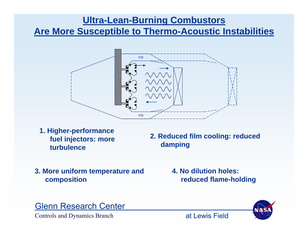
2. Reduced film cooling: reduced damping
3. More uniform temperature and composition
1. Higher-performance fuel injectors: more turbulence
4. No dilution holes: reduced flame-holding
Ultra-Lean-Burning Combustors Are More Susceptible to Thermo-Acoustic Instabilities
Controls and Dynamics Branch at Lewis FieldGlenn Research Center
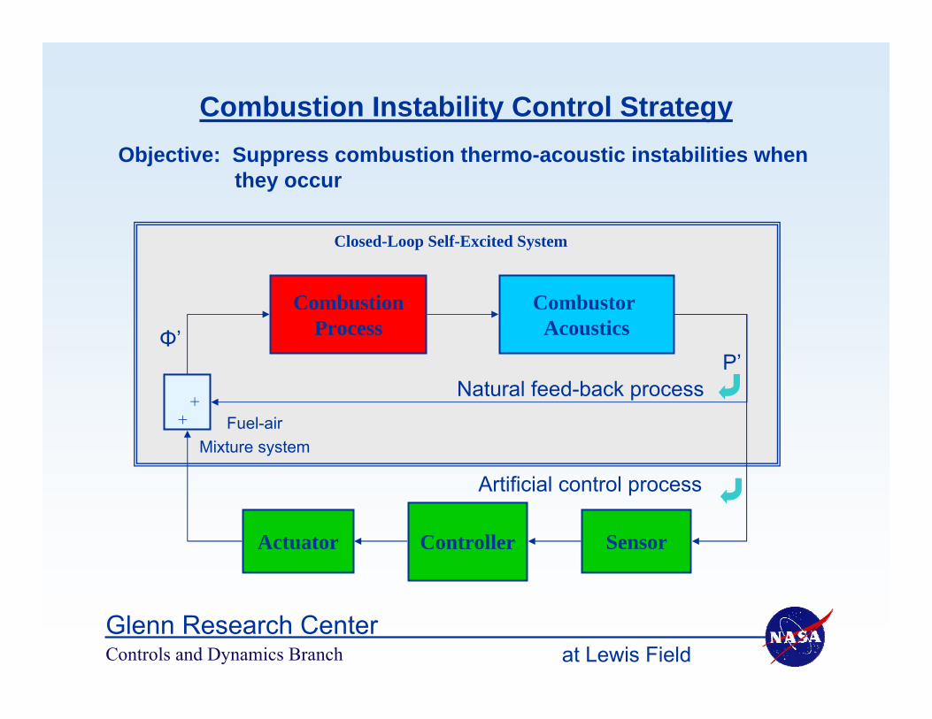
Combustion Instability Control StrategyObjective: Suppress combustion thermo-acoustic instabilities when
they occur
Combustor Acoustics
CombustionProcess
SensorControllerActuator
++
Closed-Loop Self-Excited System
Natural feed-back process
Artificial control process
Fuel-airMixture system
Φ’P’
Controls and Dynamics Branch at Lewis FieldGlenn Research Center
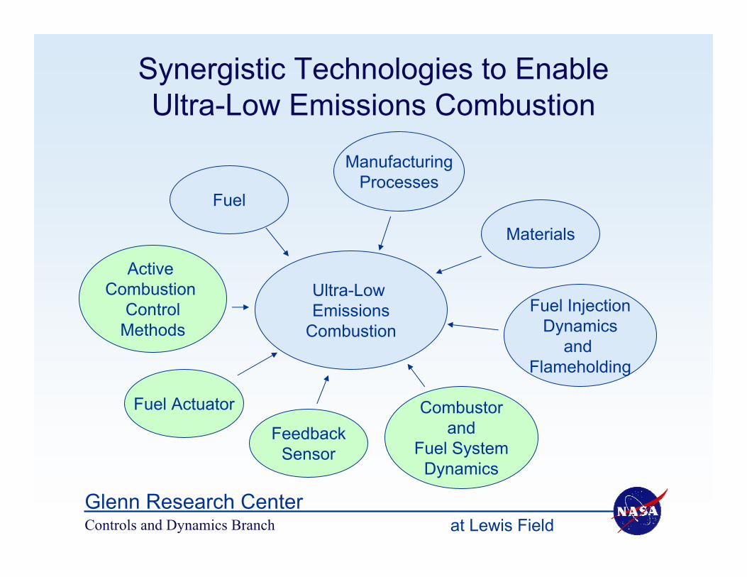
Synergistic Technologies to Enable Ultra-Low Emissions Combustion
Ultra-Low Emissions
Combustion
Fuel
Fuel InjectionDynamics
and Flameholding
Materials
FeedbackSensor
Fuel Actuator
Active Combustion
ControlMethods
ManufacturingProcesses
Combustorand
Fuel SystemDynamics

Controls and Dynamics Branch at Lewis FieldGlenn Research Center
Active Combustion Control - Technical Challenges• Combustor dynamics largely unmodeled
• Noisy environment
• Liquid fuel – introduces additional unmodeled dynamics including time delay (atomization, vaporization, …)
• Actuation system – enough bandwidth and authority, not just valve (also feedline, injection, …)
• Simplified models needed for control design evaluation
• Control methods that can: – identify instability– suppress instability in presence of large time delay, substantial
noise, unmodeled dynamics
• Realistic experimental testbeds (combustor, actuation system)
Controls and Dynamics Branch at Lewis FieldGlenn Research Center
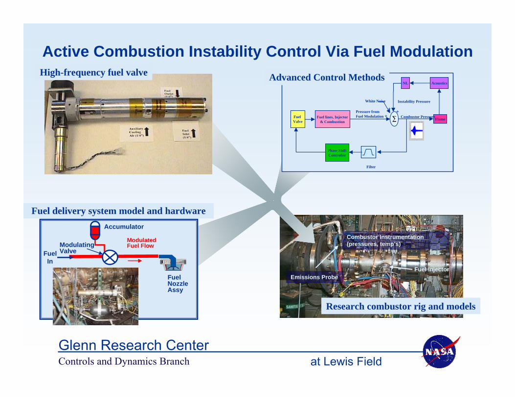
Combustor Instrumentation (pressures, temp’s)
Fuel InjectorEmissions Probe
Research combustor rig and models
Fuel delivery system model and hardwareAccumulator
ModulatingValveFuel
In
Fuel NozzleAssy
Modulated Fuel Flow
Active Combustion Instability Control Via Fuel ModulationHigh-frequency fuel valve
Phase ShiftController
Fuel Valve
Fuel lines, Injector& Combustion Σ
AcousticsNL
Flame
White Noise
+++
Filter
Pressure fromFuel Modulation Combustor Pressure
Instability Pressure
Advanced Control Methods

Controls and Dynamics Branch at Lewis FieldGlenn Research Center
Combustion Dynamics Modeling
Detailed, physics-based dynamic models
Fundamental understanding of combustor dynamics to aid passive,
active instability suppression
vt: -130 -115 -100 -85 -70 -55 -40 -25 -10 5 20 35 50
Penn State Injector Response Model Plot
Simplified Quasi-1D dynamic models
Allow physics-based control method validation
Results from NASA Sectored-1D Model of LPP
Combustor Rig – D. Paxson
0 500 1000 1500 200010
−10
10−8
10−6
10−4
10−2
100
Pow
er D
ensi
ty (
psi*
*2/h
z.)
Frequency (hz.)
ComputedMeasured
Reduced-order oscillator models
Run fast to allow parametric studies in support of control
system development
Combustor Acoustics
CombustionProcess
Controls and Dynamics Branch at Lewis FieldGlenn Research Center
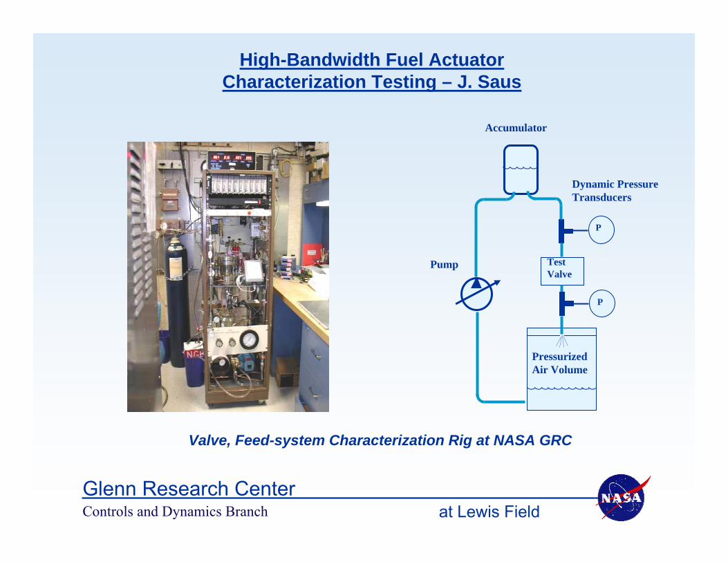
High-Bandwidth Fuel Actuator Characterization Testing – J. Saus
PressurizedAir Volume
P
TestValve
P
Pump
Accumulator
Dynamic PressureTransducers
Valve, Feed-system Characterization Rig at NASA GRC

Controls and Dynamics Branch at Lewis FieldGlenn Research Center
GaTech high-response fuel valve in characterization rig in CE7A
Frequency Response Dynamic Characterization Data
High-Bandwidth Fuel Actuator
Fuel Delivery System Dynamic Response
Stroboscopic Image of Dynamic Fuel Injection
SecondaryFuel
PrimaryFuel
0
0.05
0.1
0.15
0.2
DP23
a/in
put,
psi
/vol
t
-1080
-900
-720
-540
-360
-180
0
180
360
0 500 1000 1500 2000 2500Frequency, Hz
Pha
se, de
g
0ft-1V1ft-1V2ft-1V

Controls and Dynamics Branch at Lewis FieldGlenn Research Center
Adaptive phase shifting control:“Adaptive Sliding Phasor Averaged Control” – G. Kopasakis
Phase ShiftController
Fuel Valve
Fuel lines, Injector& Combustion Σ
AcousticsNL
Flame
White Noise
++
+
Filter
Pressure fromFuel Modulation Combustor Pressure
Instability Pressure
Pressure from instability
Pressure from Fuel modulation
Boundary of effective stability region
Overall combustor pressure
Boundary of restricted control region

Controls and Dynamics Branch at Lewis FieldGlenn Research Center
Model-Based Control:“Multi-Scale Extended Kalman Control” – D.K. Le
EK StatesPredictor
ParameterTuning
Time-Scale Averaged Pressure Variance
Sensedcombustion
pressure
Fuelmodulationcommand
Multi-ScaleTones Analysis
Damper
Suppression
Phase Drift Estimation
Phase-AdjustedReconstruction

Controls and Dynamics Branch at Lewis FieldGlenn Research Center
100 200 300 400 500 600 700 8000
2
4
6
8
10
12
Ampl
itude
, psi
Frequency, Hz
pla1c1, Run 423 and 425, 040527 - 040603
Active Combustion Instability Control Demonstrated Experimentally
Liquid-fueled combustor rig emulates engine observed instability behavior at engine pressures, temperatures, flows
Large amplitude, low-frequency instability suppressed by 90%
High-frequency, low-amplitude instability is identified, while still small, and suppressed almost to the noise floor. •0 •100 •200 •300 •400 •500 •600 •700 •800 •900 •1000
•0
•0.05
•0.1
•0.15
•0.2
•0.25
•0.3
•0.35
•0.4
•Am
plitu
de, p
si•Frequency, Hz
•Open-loop•Adaptive Phase-Shift Control
Controls and Dynamics Branch at Lewis FieldGlenn Research Center
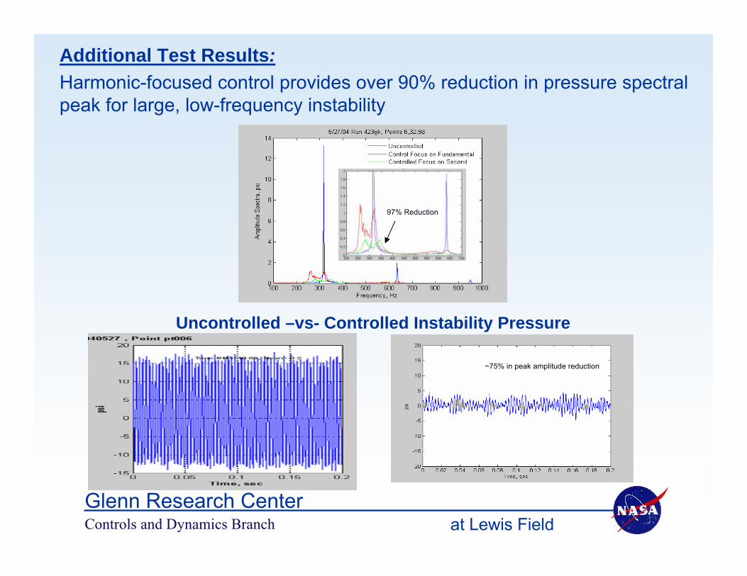
Additional Test Results:Harmonic-focused control provides over 90% reduction in pressure spectralpeak for large, low-frequency instability
Uncontrolled –vs- Controlled Instability Pressure
97% Reduction
~75% in peak amplitude reduction

Controls and Dynamics Branch at Lewis FieldGlenn Research Center
0 200 400 600 8000
2
4
6
8
10
12
F re q ue ncy, Hz
P L A1C1psi
Max=11.82 @ 314 .94H z , P S D R MS =9.56
Ru n 425, 040602 , P o in t p t016
0 5 10-15
-10
-5
0
5
10
15
20
psi
T im e , se c
Tim e R MS =9.56 , Mean =-0 .2
0 200 400 600 8000
0.5
1
1.5
2
2.5
3
3.5
F re q u e n cy, Hz
P L A1C1p si
Max=3 .16 @ 100 .1H z , P S D R MS =3.04
Ru n 425, 040602 , P o in t p t023
0 5 10-15
-10
-5
0
5
10
15
psi
T im e , se c
Ti m e R MS =3.07 , Mean =-0 . 3
Uncontrolled
Open-loop perturbations at 100Hz
Additional Test observations: Open-loop 100 Hz fuel valve perturbations shows substantial interference with 315Hz instability

Controls and Dynamics Branch at Lewis FieldGlenn Research Center
• Increasing fuel flow increases 530Hz combustion instability, preventing full-power operation
• Continuing research to demonstrate instability control/suppression:
– Apply advanced NASA modeling, control, actuation methods
Recent Results – Lean, Low-Emissions Combustor Instability Characterization
Active Control may extend lean, low-emissions combustor operationActive Control may extend lean, low-emissions combustor operation
Combustor Pressure Oscillations
Amplitude
FrequencySpectra

Controls and Dynamics Branch at Lewis FieldGlenn Research Center
Simulation of Combustion Instabilities:A Sectored-One-Dimensional Approach
Daniel E. PaxsonNASA Glenn Research Center
Cleveland, Ohio216-433-8334
Propulsion Controls and Diagnostics WorkshopCleveland, Ohio, November 2007

Controls and Dynamics Branch at Lewis FieldGlenn Research Center
Discussion Outline
• Motivation• Simulation Methodology Description• Results• Comments

Controls and Dynamics Branch at Lewis FieldGlenn Research Center
Motivation
• Low emission combustors may be susceptible to thermo-acoustic combustion instabilities.
• One possible solution to the this problem is active control.• Successful active control design requires accurate modeling and
simulation.– The essential physical phenomena should be correctly captured (e.g. self-
excitation).– Characterization and a control design necessitate rapid simulation (i.e.
relative simplicity).– Simulation must lend itself to implementing a variety of sensing and actuation
strategies.
For combustor configurations in which the potential instabilities propagate axially, but which contain abrupt changes in cross sectional area, the method to be described can achieve the simulation goals.

Controls and Dynamics Branch at Lewis FieldGlenn Research Center
Sector 2
Sector 3
Injector Region
Combustor Region
Description-Simplifications
• One-Dimensional• Perfect Gas
Within Each Sector:
Sector 1

Controls and Dynamics Branch at Lewis FieldGlenn Research Center
Description-Governing Equations
⎥⎥⎥⎥⎥⎥⎥
⎦
⎤
⎢⎢⎢⎢⎢⎢⎢
⎣
⎡
⎟⎟⎠
⎞⎜⎜⎝
⎛+
−
+
=
ρuz2ρu
1pu
ρupρu
F 2
2
γ
γ
⎥⎥⎥⎥⎥
⎦
⎤
⎢⎢⎢⎢⎢
⎣
⎡
+γ
=
ρz2
ρu1)-(
pρuρ
w 2
γ
x),w(Sx
)w(Ftw
=∂
∂+
∂∂
⎥⎥⎥⎥⎥⎥⎥⎥⎥⎥⎥
⎦
⎤
⎢⎢⎢⎢⎢⎢⎢⎢⎢⎢⎢
⎣
⎡
+−⎟⎟⎠
⎞⎜⎜⎝
⎛⎟⎠⎞
⎜⎝⎛∂∂
∂∂
+
++−γ
+⎟⎟⎠
⎞⎜⎜⎝
⎛⎟⎟⎠
⎞⎜⎜⎝
⎛−γ
+∂∂
∂∂
+⎟⎟⎠
⎞⎜⎜⎝
⎛⎟⎠⎞
⎜⎝⎛∂∂
∂∂
=
sst
*t
r
ht0s
0
t
2
*t
0.752*
t
s
zmRxz
ScRexm
QRq1
mT1)Pr(T
2u
xRex
uuxu
Rex
m
x),w(S
ε
ε
ρσε
( )⎭⎬⎫
⎩⎨⎧
<>−
−=igni
igniiign210 TT;0
TT;TT1z)ζρz(ζKR
)T(TQ iinfht −α=
• Reactive Euler Equations with Source Terms
• MacCormack’s Method– Fast– Second Order Accurate
• Artificial Viscosity– Baldwin-MacCormack– Density Instead of Pressure
• Uniform Grid Spacing– Relatively Course– Requires Some “Tuning” (e.g. eddy
viscosity, reaction rates)• Sectors Joined With Compatible
Boundary Conditions– Multi-block Approach– Nothing “Stored” @ Interface

Controls and Dynamics Branch at Lewis FieldGlenn Research Center
Initial Tests-Conical Pipe Acoustics
0.0
0.5
1.0
0.0 0.2 0.4 0.6 0.8 1.0x/L
A/A
*
Q-1-DSectored
pressuremeasurement
excitation
0.9
1.0
1.1
1.2
0 10 20 30 40 50
Non-Dimensional Time
p/p*
SectoredQ-1-D
• Theoretical resonant frequencies are integer multiples of the fundamental.
• Q-1-D and Sectored models agree• 100 numerical cells.

Controls and Dynamics Branch at Lewis FieldGlenn Research Center
Validation-Valveless Pulsejet
1.00.56
0.350.22 0.19
0.109 0.144 0.249 0.249 0.249
Tailpipe
CombustionChamber
IntakeFuel Injection
• Coupling between heat release and acoustic modes is self-excited.
• No external, forced excitation.
• Geometry approximates a functional pulsejet.
• Frequency is correct.• 200 cells.
-0.005
0.000
0.005
0.010
0.015
0.020
0.025
0.0 1.0 2.0 3.0 4.0 5.0Non-Dimensional Time
Ray
leig
h In
tegr
al, R
a ∫ ′′=1
00 dxpRqRa

Controls and Dynamics Branch at Lewis FieldGlenn Research Center
Comparison With ExperimentGRC CE-5 LPP
0.0
5.0
10.0
15.0
20.0
0 20 40 60 80 100
x (inches)
Hyd
raul
ic D
iam
eter
(inc
hes)
Fuel injectionCooling
Tee-section exhaust
Combustor
Pressuretransducer
• Exhaust modeled as mass extraction.
• Cooling spray modeled as a high heat transfer region.
• Flame position adjusted with turbulent diffusivity distribution.
• Noise added at inlet boundary.
• 350 cells, CPU time=1600 integration time .
Constant pressure boundary Wall boundary
Controls and Dynamics Branch at Lewis FieldGlenn Research Center
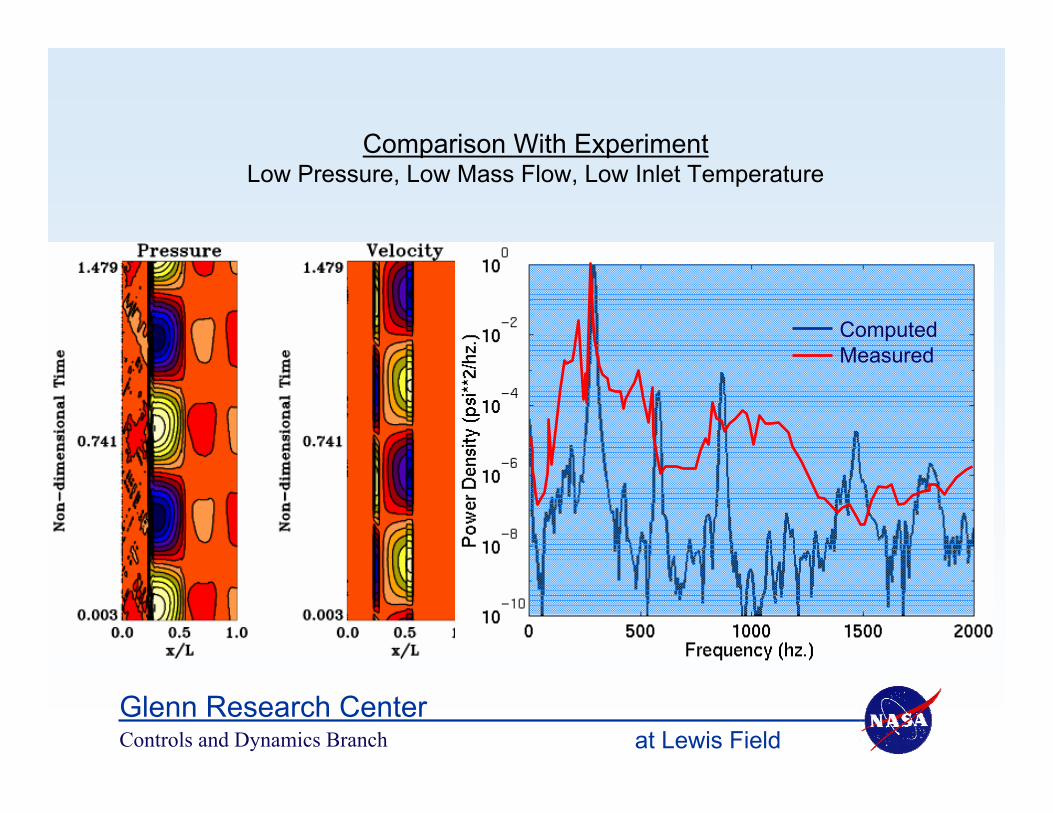
Comparison With ExperimentLow Pressure, Low Mass Flow, Low Inlet Temperature
ComputedMeasured

Controls and Dynamics Branch at Lewis FieldGlenn Research Center
ComputedMeasured
Comparison With ExperimentHigh Pressure, High Mass Flow, High Inlet Temperature

Controls and Dynamics Branch at Lewis FieldGlenn Research Center
02
46
810
121416
0 5 10 15 20Axial Distance (in.)
Cro
ss S
ectio
nal A
rea
(in.2
) CombustorDiffuser & Plenum
Injector
Comparison With ExperimentGRC CE-9 SNR
constant mass flow boundarychoked boundary
transducer
• Weak oscillations @ approx. 500 hz.• “Pink” noise at injector (momentum source)• Helmoltz-like.
RigSimulation
0
5
10
15
20
25
30
0 10 20 30 40Axial Distance (in.)
Cro
ss S
ectio
nal A
rea
(in.2
)
CombustorDiffuser & Plenum
Injector
constant mass flow boundarychoked boundary
transducer
RigSimulation
• Strong oscillations @ approx. 300 hz.
0
5
10
15
20
25
30
0 10 20 30Axial Distance (in.)
Cro
ss S
ectio
nal A
rea
(in.2
)
CombustorDiffuser & Plenum
Injector
RigSimulation
transducer
• Strong oscillations @ approx. 350 hz.• Simulation preceded testing (i.e.
predicitve)
constant mass flow boundarychoked boundary
Controls and Dynamics Branch at Lewis FieldGlenn Research Center
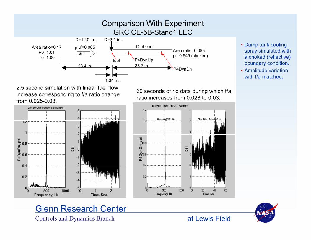
60 seconds of rig data during which f/a ratio increases from 0.028 to 0.03.
2.5 second simulation with linear fuel flow increase corresponding to f/a ratio change from 0.025-0.03.
Area ratio=0.17P0=1.01T0=1.00
ρ’u’=0.005
28.4 in. 35.7 in.
1.34 in.
D=12.0 in.D=4.0 in.
D=2.1 in.
Area ratio=0.093pr=0.545 (choked)
P4DynDn
P4DynUpfuel
air
Comparison With ExperimentGRC CE-5B-Stand1 LEC
• Dump tank cooling spray simulated with a choked (reflective) boundary condition.
• Amplitude variation with f/a matched.

Controls and Dynamics Branch at Lewis FieldGlenn Research Center
0 100 200 300 400 500 600 700 800 900 10000
0.05
0.1
0.15
0.2
0.25
0.3
0.35
0.4
Am
plitu
de, p
si
Frequency, Hz
Open-loopAdaptive Phase-Shift Control
0 500 10000
2
4
6
8
10
12
14
Frequency, Hz
PLA1C1psi
Max=13.26 @ 317.38Hz, PSD RMS=10.07
Run 423
Comparison With ExperimentGRC CE-9 SNR with Active Control Applied
Simulated Control
High Frequency Instability
Measured Control
Low Frequency Instability

Controls and Dynamics Branch at Lewis FieldGlenn Research Center
Sectored 1-D Model Concluding Remarks
• The sectored-one-dimensional technique has successfully simulated instabilities in a variety of combustors with complex geometries.
• Simulations run far from real-time, but fast enough for control design.
• Simulated plant responses to control match measured responses.
• Some success shown in prediction of instabilities, but “tuning” of some parameters is still required.
• More work is therefore needed to model complex phenomena in a 1-D compatible fashion.

Controls and Dynamics Branch at Lewis FieldGlenn Research Center
Active Combustion Control for Ultra Low Emissions in
Aircraft Gas-Turbine Engines
Current Directions and Future Plans
John DeLaatControls and Dynamics Branch
Ph: (216) 433-3744email: [email protected]

Controls and Dynamics Branch at Lewis FieldGlenn Research Center
Current Directions and Future Plans
• Penn State and Virginia Tech– Active fuel nozzle, flame transfer
function
• Georgia Tech– Integrated control of:
• Dynamic stability margin• Static stability margin• Dynamic stability mitigation
quartz combustor
Combustor test rig for flame response measurements
fuelfuel modulation actuator
LDI injector
2-D Spray Image
quartz combustor
Combustor test rig for flame response measurements
fuelfuel modulation actuator
LDI injector
2-D Spray Image
1 5 2 0 2 5 3 0 3 5 4 00
0 . 1
0 . 2
0 . 3
0 . 4
Slo
pe A
utoc
orre
latio
n C
urve
(o)
Pre
ssur
e A
mpl
itude
(+)
1
2
3
0
4
In le t V e lo c ity ( m /s )
stable
NRA Cooperative Agreements

Controls and Dynamics Branch at Lewis FieldGlenn Research Center
Current Directions and Future Plans• Current platform - lean combustor concept (not LDI)
– Actuator research for small “pilot” flows– Dynamic model validation– Instability control demonstration
• Future platform - LDI Multi-point injection– Fundamentals rig in CE7C– High pressure testing in CE5, ASCR– Control methods that exploit multipoint injection– Multidimensional models
• Incorporate technologies from NRA’s
• Harmonic, sub-harmonic models and control
Controls and Dynamics Branch at Lewis FieldGlenn Research Center
Opportunities for Collaboration
• NRA’s, SBIR – Watch solicitations. Future topics TBD• SAA’s – Have one in place, others welcome
• Requirements definition and feedback (engine, HW mfrs)• Realistic testbeds for technology transfer• Control methods integration and field testing• Modeling methods field testing• Multidimensional models development• Actuator systems, associated models development, field testing

Controls and Dynamics Branch at Lewis FieldGlenn Research Center
Concluding Remarks - Long Term Goal for Active Combustion Control
• Improve fundamental understanding of the combustor processes
in order to…• More effectively integrate multi-point combustor
design, controls, sensor, and actuator technologies to provide…
– An intelligent fuel/air management system with temporal and spatial fuel modulation for
• Instability avoidance/suppression– Thermoacoustics, blowout
• Pattern factor control• Emissions minimization
to enable…Combustors with extremely low emissions throughout the engine operating envelope

Controls and Dynamics Branch at Lewis FieldGlenn Research Center
References• Paxson, D.: “A Sectored-One-Dimensional Model for Simulating Combustion Instabilities in Premix Combustors,”
presented at the 38th Aerospace Sciences Meeting & Exhibit. AIAA-2000-0313, NASA TM-1999-209771, January 2000.
• Cohen, J.M. et al: "Experimental Replication of an Aeroengine Combustion Instability," International Gas Turbine & Aeroengine Congress & Exhibition, Munich, Germany, ASME Paper 2000-GT-0093, May 2000.
• DeLaat, J.C.; Breisacher, K.J.; Saus, J.R.; Paxson, D.E.: “Active Combustion Control for Aircraft Gas Turbine Engines.” Presented at the 36th Joint Propulsion Conference and Exposition, Huntsville, Alabama, July 17-19, 2000. NASA TM 2000-210346, AIAA –2000-3500.
• Le, D.K.; DeLaat, J.C.; Chang, C.T.; Vrnak, D.R.: “Model-Based Self-Tuning Multiscale Method for Combustion Control.” Presented at the 41st Joint Propulsion Conference and Exhibit cosponsored by the AIAA, ASME, SAE, and ASEE, Tucson, Arizona, July 10-13, 2005. AIAA-2005-3593.
• Kopasakis, G.; DeLaat, J.; Chang, C.: “Validation of an Adaptive Combustion Instability Control Method for Gas-Turbine Engines,” 40th Joint Propulsion Conference and Exhibit, Ft. Lauderdale, FL, AIAA-2004-4028, NASA TM-2004-213198, October 2004.
• DeLaat, J.C.; Chang, C.T.: "Active Control of High Frequency Combustion Instability in Aircraft Gas-Turbine Engines," 16th International Symposium on Airbreathing Engines, Cleveland, OH, ISABE-2003-1054, NASA TM-2003-212611, September 2003.
• Cohen, J.M.; Proscia, W; and DeLaat, J.C.: “Characterization and Control of Aeroengine Combustion Instability: Pratt & Whitney and NASA Experience.” In “Combustion Instabilities in Gas Turbine Engines, Operational Experience, Fundamental Mechanisms, and Modeling”, AIAA Progress in Astronautics and Aeronautics series, Tim Lieuwen, Vigor Yang editors, Chapter 6, p. 113-145, October 2005.
• Okojie, R.S.; DeLaat, J.C.; Saus, J.R.: “SiC Pressure Sensor for Detection of Combustor Thermo-Acoustic Instabilities.” Presented at the 13th International Conference on Solid-State Sensors, Actuators and Microsystems, Seoul, Orea, June 5-9, 2005. Volume 1, p. 470-473.