209368303 gas-turbine-combustion-chambers
TRANSCRIPT
UNIVERSITY OF WEST BOHEMIAFACULTY OF MECHANICAL ENGINEERING
DEPARTMENT OF POWER SYSTEM ENGINEERING

JET ENGINESJET ENGINES
COMBUSTION CHAMBERSCOMBUSTION CHAMBERS

INTRODUCTION
PURPOSE● In combustion chamber provides conversion of fuel chemical
energy to heat energy
● The combustion chamber has the difficult task of burning large quantities of fuel, supplied through the fuel spray nozzles, with extensive volumes of air, supplied by the compressor, and releasing the heat in such a manner that the air is expanded and accelerated to give a smooth stream of uniformly heated gas at all conditions required by the turbine. This task must be accomplished with the minimum loss in pressure and with the maximum heat release for the limited space available

INTRODUCTION
REQUIREMENTS● Easy and safety mixture ignition in every
working conditions● Stable mixture burning in every engine mode● Uniform pressure and velocity field in outlet● Low hydraulic losses● Short length of flame

INTRODUCTION
MAIN PROBLEMS● Very hight heat load of combustion area● High heat dilatation● Very high combustion temperature ( up to
2000K )● Problematic ignition● Stability of burning

MAIN CONSTRUCTION

COMBUSTION PROCESS
● Air from compressor enters the combustion chamber at a velocity approximately 100-150 m.s-1
● At first air is apportioned in CC snout to:● Primary flow (20-40% of air)
● Secondary flow (60-80% of air)
● In primary flow provides a fuel burning and dilution
● This velocity of inlet air from compressor is far too high for combustion and it is necessary to decelerate it
● Deceleration is provided by swirl vanes and flare
● Air is decelerated to speed of burning which is around 15-20 m.s-1
● In primary zone is air mixed with fuel from spray nozzle and it is ignited by electric spark. Temperature in core of burning achieve 1800-2000 °C.
● Air from secondary flow enter through holes and cool the flame tube
● In dilution zone air from secondary stabilize and make uniform the outlet flow

COMBUSTION PROCESS
Fig. Combustion process in p-V and T-s diagram

PARAMETERS
Fig. Evolution of parameters through CC
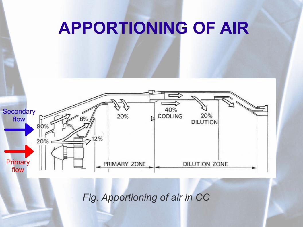
APPORTIONING OF AIR
Primaryflow
Secondaryflow
Fig. Apportioning of air in CC

FLAME STABILIZING
Fig. Flame stabilizing in CC

HEAT INLET TO CC
● Burning – chemical proces ( severe oxidation )● Exothermically reaction – release of heat● Condition of burning – it's necessary two
components● Fuel ( JET A-1, PL – 7)
– Oil-based hydrocarbon compound ( 86% C + 14% H2)
● Oxygen ( O2 is 23,3% of air)

HEAT INLET TO CC
● Types of burning● Ideal burning
● C+O2 = CO
2 + heat
● H2+1/2*O
2 = H
2O + heat
● Non-ideal burning● 2C+O
2 → 2CO
2 + heat
● 2H2+O
2 → 2H
2O + heat
HEAT INLET TO CC
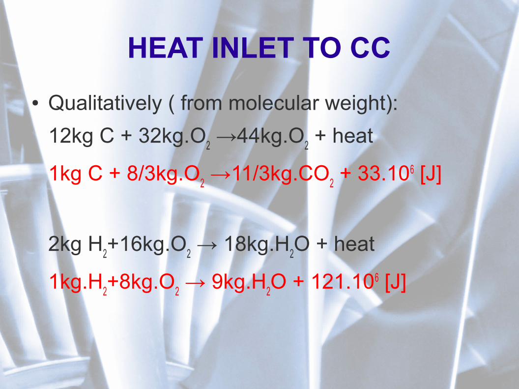
● Qualitatively ( from molecular weight):
12kg C + 32kg.O2 →44kg.O
2 + heat
1kg C + 8/3kg.O2 →11/3kg.CO
2 + 33.106 [J]
2kg H2+16kg.O
2 → 18kg.H
2O + heat
1kg.H2+8kg.O
2 → 9kg.H
2O + 121.106 [J]

NECESSARY OXYGEN/AIR
● Necessary oxygen for burning of 1kg fuel:
mO2=8mH+8/3mC
mO2=8*0,14+8/3*0,86
mO2=3,14 kg O
2
● Assumption: O2 is 23,2% of air
mAIR
=mO2/0,232=14,68 kg AIR = l
0
l0 - theoretical quantity of air for burning of 1kg
hydrocarbon fuel

NECESSARY OXYGEN/AIR
● Of course l0 is not enough, because temperature of gases is too high and its
necessary to mix with cooler air. Its mean that is necessary provide α*l0 air
for burning of 1kg of fuel
Qv – air flow through CC [kg.s-1]
Qf – fuel flow through CC [kg.s-1]
α – coefficient of air overflow [1] (3,5 – 4,5)
l0 – theoretical quantity of air for burning of 1kg hydrocarbon fuel
Q v=Q f l0

BASIC PARAMETERS
α – coefficient of air overflow
=real quantity of air for burning of 1 kg of fuel l
theoretical quantity of air for burning of 1 kg of fuel l0

BASIC PARAMETERS
● Heat (calorific) value of fuel Hu
● Define heat properties of fuel● Define a quantity of heat at ideal fuel burn● For PL-6 – 43123 [kJ.kg-1]
● Heat (calorific) value of mixture Hum
H um=H u
1 l 0

BASIC PARAMETERS
● Absolute pressure losses
● Burning efficiency
CC=p3T
p2T
[1]
b=real heat release during burning
theoretical heat release during burning

BASIC PARAMETERS
● Quantum of released head
● Equation of energy conservation
q=bH u
q=i 3gc3
2
2 1 l0−i 2ac2
2
2 l 0

CONSTRUTION TYPES
● Multiple● Annular● Turbo-annular (combined) ● Pooled
Multiple Annular Combined

MULTIPLE CONSTRUCTION

MULTIPLE CONSTRUCTION
Multiple combustion chamber - VK-1

ANNULAR CONSTRUCTION

ANNULAR CONSTRUCTION
Annular combustion chamber - R-29B-300

TURBO-ANNULAR CONSTRUCTION

TURBO-ANNULAR CONSTRUCTION
Turbo-annular combustion chamber - R11F-300

POOLED CONSTRUCTION

REFERENCES
● Otis, Vosbury: Aircraft gas turbine powerplants – Jeppesen: 2002
● Rolls royce – The jet engine, 1996● Hanus D., Maršálek J, : Studijní modul 15,
Turbínový motor, CERM, s.r.o. Brno 2004● Kadrnožka J.: Tepelné turbíny a
turbokompresory, CERM, s.r.o. Brno 2004

DISCUSSION...
...QUESTIONS