accel 49310 ignition kit installation instructions - jegs.com · 2 accel this illustrated booklet...
TRANSCRIPT
Installation Instructions for theACCEL 300plus ThunderSport
Ignition Kit #49310
Cleveland, Ohio216.398.8300
www.mrgasket.com
1
ACCELINTRODUCTION
The ACCEL 300plus ThunderSport Ignition Kit #49310 isdesigned to convert your Honda or Acura’s factory-equipped, inductively-charged internal coil ignition systemto a high performance, multi-strike, capacitive-dischargedexternal coil system. The conversion from the stock internalcoil to an external coil set-up is necessary because the highvoltage and amperage outputs of the ACCEL 300plusThunderSport control box could easily overheat and burnout the windings of the small internal factory coil.
This kit is designed to be installed without any permanentchanges to the stock factory wiring harnesses. No cutting orsplicing of any factory wiring is necessary. By saving all thefactory stock component parts removed during theinstallation of the ACCEL 300plus ThunderSport ignitionsystem, you can easily return your engine’s ignition systemback to factory stock status.
This kit includes the following parts:
Qty. Part Number Description
(1) 49310 300plus ThunderSportignition control box
(1) 140019 CD E-core ignition coil
(1) M49310 Harness
(1) 120500 Distributor cap
(4) Hardware kits:INKT1 mounting hardwareINKT7 universal coil lead wire kitINKT9 coil by-pass wiring kitINKT10 vibration isolation kit
2
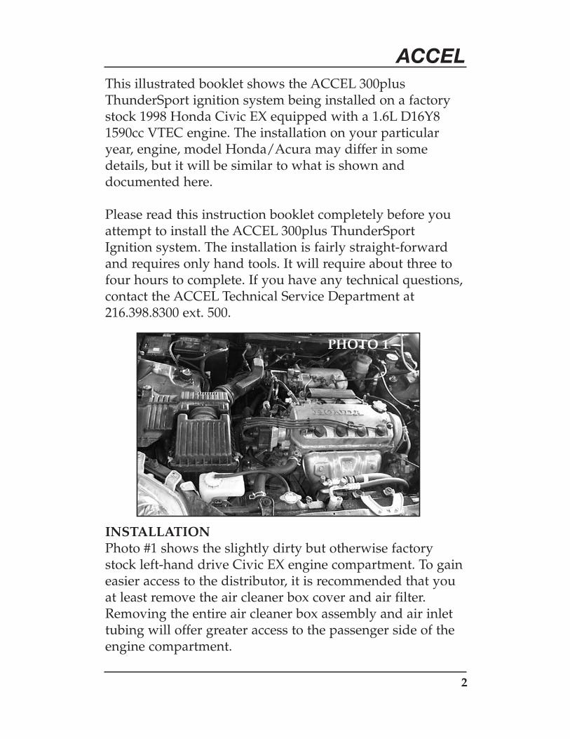
ACCELThis illustrated booklet shows the ACCEL 300plusThunderSport ignition system being installed on a factorystock 1998 Honda Civic EX equipped with a 1.6L D16Y81590cc VTEC engine. The installation on your particularyear, engine, model Honda/Acura may differ in somedetails, but it will be similar to what is shown anddocumented here.
Please read this instruction booklet completely before youattempt to install the ACCEL 300plus ThunderSportIgnition system. The installation is fairly straight-forwardand requires only hand tools. It will require about three tofour hours to complete. If you have any technical questions,contact the ACCEL Technical Service Department at216.398.8300 ext. 500.
INSTALLATIONPhoto #1 shows the slightly dirty but otherwise factorystock left-hand drive Civic EX engine compartment. To gaineasier access to the distributor, it is recommended that youat least remove the air cleaner box cover and air filter.Removing the entire air cleaner box assembly and air inlettubing will offer greater access to the passenger side of theengine compartment.
PHOTO 1

3
ACCEL1) Do NOT remove the spark plug wires from the distributor
cap at this time. Remove the distributor cap from thedistributor by removing the three screws that secure thedistributor cap to the distributor. Set the distributor capaside with the spark plug wires still attached.
2) Note that the rotor is secured on the distributor shaft bya Phillips head screw (see photo #2). If the screw is notvisible, you will have to jog the engine until it becomesvisible. This can be done by yourself, but it is easier andquicker with the help of a second person. Once the screwis visible, disconnect the negative battery cable and set itaside so that it can’t come into contact with the negativebattery terminal. Remove the Phillips screw and slide therotor off the distributor shaft. Note the condition of therotor tip. If it is in good condition, it can be carefullycleaned with an emery cloth or fine grade sand paperand reused. If the rotor tip is burnt, heavily oxidized orpitted, the rotor should be replaced.
PHOTO 2
4
ACCEL
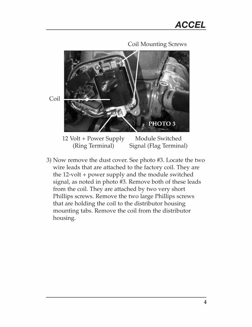
3) Now remove the dust cover. See photo #3. Locate the twowire leads that are attached to the factory coil. They arethe 12-volt + power supply and the module switchedsignal, as noted in photo #3. Remove both of these leadsfrom the coil. They are attached by two very shortPhillips screws. Remove the two large Phillips screwsthat are holding the coil to the distributor housingmounting tabs. Remove the coil from the distributorhousing.
PHOTO 3
Coil Mounting Screws
12 Volt + Power Supply(Ring Terminal)
Module SwitchedSignal (Flag Terminal)
Coil
5
ACCEL
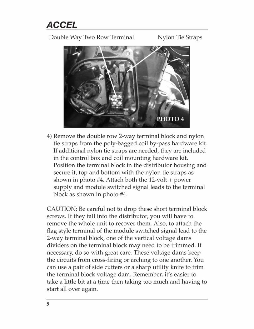
4) Remove the double row 2-way terminal block and nylontie straps from the poly-bagged coil by-pass hardware kit.If additional nylon tie straps are needed, they are includedin the control box and coil mounting hardware kit.Position the terminal block in the distributor housing andsecure it, top and bottom with the nylon tie straps asshown in photo #4. Attach both the 12-volt + powersupply and module switched signal leads to the terminalblock as shown in photo #4.
CAUTION: Be careful not to drop these short terminal blockscrews. If they fall into the distributor, you will have toremove the whole unit to recover them. Also, to attach theflag style terminal of the module switched signal lead to the2-way terminal block, one of the vertical voltage damsdividers on the terminal block may need to be trimmed. Ifnecessary, do so with great care. These voltage dams keepthe circuits from cross-firing or arching to one another. Youcan use a pair of side cutters or a sharp utility knife to trimthe terminal block voltage dam. Remember, it’s easier totake a little bit at a time then taking too much and having tostart all over again.
PHOTO 4
Nylon Tie StrapsDouble Way Two Row Terminal

6
ACCEL
5) The supplied ACCEL Distributor Cap #120500 has beendesigned with an integral center or fifth tower for theexternal coil lead. You will have to drill a 3/8” pass-through hole in this cap so that the ACCEL external wireharness can be attached to the terminal block inside thedistributor. For most applications, the best location todrill this pass-through hole in the ACCEL DistributorCap is indicated by the dot on the side of the distributorcap as shown in photo #5. The easiest way to drill thishole is by using a drill press, a hand drill or a rotarypower tool. DO NOT apply too much pressure while youare drilling or you will crack the distributor cap. Once thehole is drilled, clean up any material around both theinside and outside edges of the pass-through hole.
PHOTO 51”
9/16”
Pass Through Hole Drill Location

7
ACCEL
6) Thread the ring terminals on the ends of both the whiteand red leads on the ACCEL wiring harness through thenew pass-through hole in the distributor cap from theoutside. Carefully seat the black rubber grommet foundon the harness, around the red and white leads wires,into the pass-through hole in the distributor cap asshown in photo #6. A small screw driver or similar toolwill help to position the grommet so that it seals flat onboth the inside and outside of the distributor cap. Thisgrommet provides a seal against the elements andprevents chaffing of the red and white lead wires againstthe edges of the pass-through hole in the distributor cap.
PHOTO 6
Seated Grommet in Pass-Through Hole

8
ACCEL
7) Inspect the black rubber gasket that seals the distributorcap to the distributor. If it shows signs of being worn,replace it with the new one included in the distributorcap box. Carefully pull the red and white lead wiresthrough the distributor cap to give yourself enough slackto work with. Route the ACCEL red and white harnessleads into the distributor, under, behind and around theterminal block as shown in photo #7. Attach the redharness lead to the terminal block directly across fromthe 12-volt + power lead and the white harness leaddirectly across from the module switched signal lead,see photo #7.
Reinstall the dust cover. Make sure that you are notpinching the red and white harness leads and that thealignment tabs are positioned correctly. The dust covermay seem loose or not seated firmly on the distributor,but once the distributor cap is installed, the dust coverwill be securely held into place. Re-install the rotor andsecure with the Phillips screw. Next, slowly slide thedistributor cap along the red and white harness leads.
PHOTO 7
9
ACCELWith a rolling motion, seat the distributor cap onto thedistributor. You will need to GENTLY pull out the slacklength of the red and white leads inside the distributorcap. You may need to be doing this while you are seat-ing the distributor cap on the distributor to avoidpinching the red and white lead wires. DO NOTexcessively pull or tug on the red and white leads, thiscould damage their connection to the terminal block andrender the ACCEL 300plus ThunderSport Ignitionsystem inoperable. Once you have removed the slack onthe red and white ACCEL harness leads, secure thedistributor cap to the distributor with the three newPhillips screws included in the distributor cap box.
Apply a small dab of RTV silicone sealant to thegrommet around the red and white lead wires toprovide a weatherproof seal. This is important inapplications where the pass-through hole on thedistributor cap is facing forward or upward. The greenlead wire in the ACCEL harness is for triggering anaftermarket tachometer. If your vehicle is not equippedwith an aftermarket tachometer, simply trim off theexposed portion of the green lead or tuck it back underthe convoluted conduit covering.
10
ACCEL
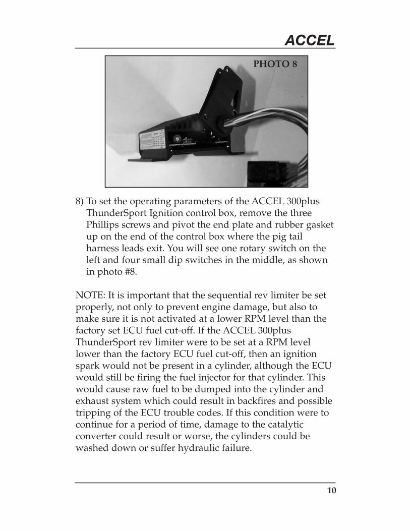
8) To set the operating parameters of the ACCEL 300plusThunderSport Ignition control box, remove the threePhillips screws and pivot the end plate and rubber gasketup on the end of the control box where the pig tailharness leads exit. You will see one rotary switch on theleft and four small dip switches in the middle, as shownin photo #8.
NOTE: It is important that the sequential rev limiter be setproperly, not only to prevent engine damage, but also tomake sure it is not activated at a lower RPM level than thefactory set ECU fuel cut-off. If the ACCEL 300plusThunderSport rev limiter were to be set at a RPM levellower than the factory ECU fuel cut-off, then an ignitionspark would not be present in a cylinder, although the ECUwould still be firing the fuel injector for that cylinder. Thiswould cause raw fuel to be dumped into the cylinder andexhaust system which could result in backfires and possibletripping of the ECU trouble codes. If this condition were tocontinue for a period of time, damage to the catalyticconverter could result or worse, the cylinders could bewashed down or suffer hydraulic failure.
PHOTO 8
11
ACCELDetermine the factory-set fuel cut-off RPM, which can befound in the factory operator’s manual and noted as themaximum recommend engine speed. This shouldcorrespond to the noted red line on the factory installedtachometer. Now it’s time to set the sequential revlimiter in the ACCEL 300plus ThunderSport control box.For this application we are going to set the rev limiter at7,000 RPM. By reading the yellow table on the side ofthe control box, set the rotary dial switch dial to “A” andthe first dip switch on the left to the “down” position.Turn on the sequential rev limit by setting the forth dipswitch to the “down” position. To tell the control boxthat your application is a four cylinder engine, you set thesecond dip switch to the “up” position and the third dipswitch to the “down” position, as shown in photo #8.Pivot the end plate and gasket back into position andsecure with the three Phillips screws.
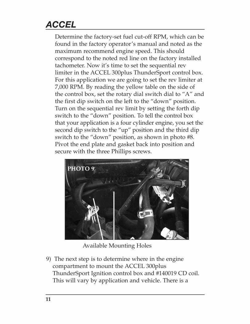
9) The next step is to determine where in the enginecompartment to mount the ACCEL 300plusThunderSport Ignition control box and #140019 CD coil.This will vary by application and vehicle. There is a
PHOTO 9
Available Mounting Holes
12
ACCELcontrol box and coil mounting hardware kit whichincludes screws, bolts, nuts and other items needed tosecure the ACCEL 300plus ThunderSport Ignition systemin your engine compartment. Both the control box andthe coil can be mounted in any orientation. Make sure themounting location that you choose is isolated fromextreme heat. For this particular installation, we decidedthat we did not want to drill any additional holes in thisvehicle’s sheet metal. Instead, we chose to mount thecontrol box on the lower passenger strut tower, using theunoccupied right-hand drive mounting bolt holes asshown in photo #9. The area near the top of thepassenger side strut tower was used to mount the coil.This required enlarging the holes in the mounting tabs ofboth the control box and the coil to accommodate therequired 8mm x 1.25mm bolts (not included in themounting hardware kit). The ACCEL harness included inthis kit is designed so that you can mount the control boxand coil in any number of locations on the passenger sideof the engine compartment. It’s all a matter of personalpreference and available space.

13
ACCEL
10) Once the control box and coil are mounted it is a simplecase of plugging in the harness. Because of the harness’sdesign, it can’t be plugged in incorrectly. The grayconnector plugs into the coil only one way, as shown inphoto #10. The two weather-sealed 4-pin connectors,one square and the other flat, plug into the correspondingconnectors on the control box’s pig tail harnesses. YouMUST connect the ring terminal on the black lead to agood ground location, preferably direct to the engineblock or uni-body. Use the rest of the nylon tie strapsand accessories to secure the harness in the enginecompartment. It is very important to keep the harnessisolated from being chaffed or damaged by movingparts and away from excessive heat.
11) Next comes the installation of the new coil lead wirethat carries the spark energy from the coil to thedistributor cap. The coil lead wire comes complete withthe distributor boot and terminal already installed onone end. Insert this end of the coil lead wire into thecenter or coil lead tower of the distributor cap. Route
PHOTO 10
ACCEL 300plus Thundersport Ignition Control Box
ACCEL #140019 CD Coil
14
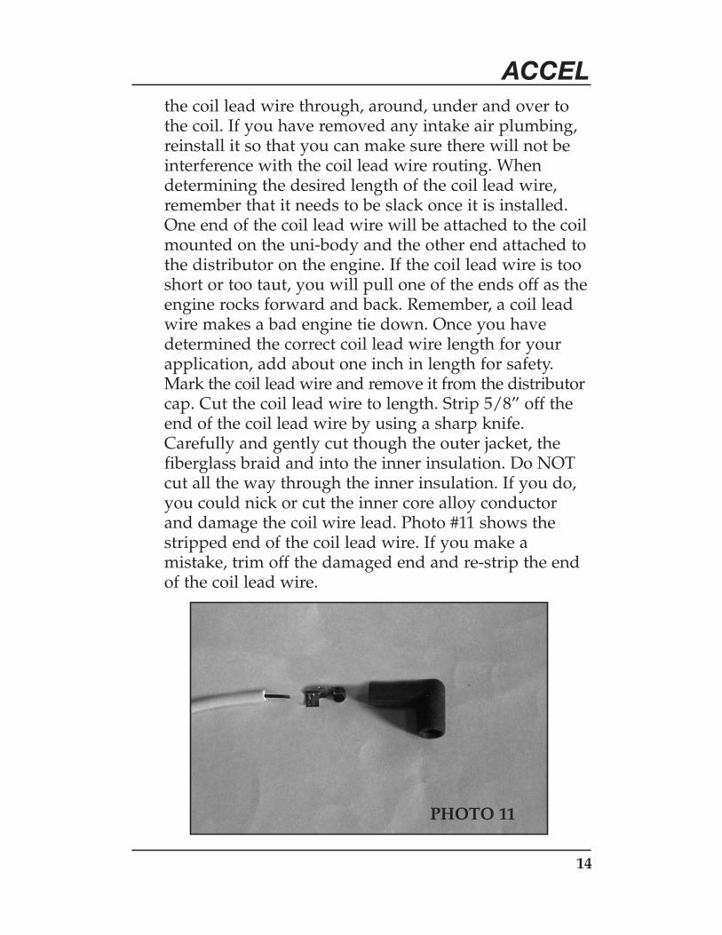
ACCELthe coil lead wire through, around, under and over tothe coil. If you have removed any intake air plumbing,reinstall it so that you can make sure there will not beinterference with the coil lead wire routing. Whendetermining the desired length of the coil lead wire,remember that it needs to be slack once it is installed.One end of the coil lead wire will be attached to the coilmounted on the uni-body and the other end attached tothe distributor on the engine. If the coil lead wire is tooshort or too taut, you will pull one of the ends off as theengine rocks forward and back. Remember, a coil leadwire makes a bad engine tie down. Once you havedetermined the correct coil lead wire length for yourapplication, add about one inch in length for safety.Mark the coil lead wire and remove it from the distributorcap. Cut the coil lead wire to length. Strip 5/8” off theend of the coil lead wire by using a sharp knife.Carefully and gently cut though the outer jacket, thefiberglass braid and into the inner insulation. Do NOTcut all the way through the inner insulation. If you do,you could nick or cut the inner core alloy conductorand damage the coil wire lead. Photo #11 shows thestripped end of the coil lead wire. If you make amistake, trim off the damaged end and re-strip the endof the coil lead wire.
PHOTO 11
15
ACCEL
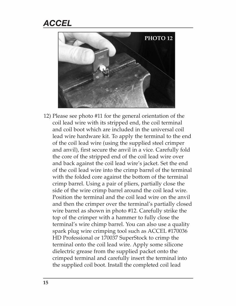
12) Please see photo #11 for the general orientation of thecoil lead wire with its stripped end, the coil terminaland coil boot which are included in the universal coillead wire hardware kit. To apply the terminal to the endof the coil lead wire (using the supplied steel crimperand anvil), first secure the anvil in a vice. Carefully foldthe core of the stripped end of the coil lead wire overand back against the coil lead wire’s jacket. Set the endof the coil lead wire into the crimp barrel of the terminalwith the folded core against the bottom of the terminalcrimp barrel. Using a pair of pliers, partially close theside of the wire crimp barrel around the coil lead wire.Position the terminal and the coil lead wire on the anviland then the crimper over the terminal’s partially closedwire barrel as shown in photo #12. Carefully strike thetop of the crimper with a hammer to fully close theterminal’s wire chimp barrel. You can also use a qualityspark plug wire crimping tool such as ACCEL #170036HD Professional or 170037 SuperStock to crimp theterminal onto the coil lead wire. Apply some siliconedielectric grease from the supplied packet onto thecrimped terminal and carefully insert the terminal intothe supplied coil boot. Install the completed coil lead
PHOTO 12

16
ACCELwire back on the distributor cap, retrace the routingthrough the engine compartment and plug the coil bootonto the output tower of the #140019 CD coil.
13) To make the most of your new-found ignition power,you should replace your factory-installed spark plugwire set. Your factory spark plug wire set has a highresistance core with about 4,500 Ohms of resistance perfoot. This high resistance can rob up to 25% of theignition energy before it can reach the spark plugs!Replace the factory wire set with a high quality, highperformance, low resistance spiral core wire set. For thisapplication, we installed an ACCEL 300plusThunderSport wire set #7913Y.
17
ACCEL
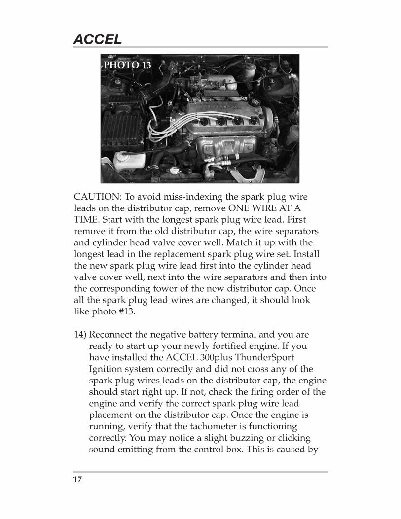
CAUTION: To avoid miss-indexing the spark plug wireleads on the distributor cap, remove ONE WIRE AT ATIME. Start with the longest spark plug wire lead. Firstremove it from the old distributor cap, the wire separatorsand cylinder head valve cover well. Match it up with thelongest lead in the replacement spark plug wire set. Installthe new spark plug wire lead first into the cylinder headvalve cover well, next into the wire separators and then intothe corresponding tower of the new distributor cap. Onceall the spark plug lead wires are changed, it should looklike photo #13.
14) Reconnect the negative battery terminal and you areready to start up your newly fortified engine. If youhave installed the ACCEL 300plus ThunderSportIgnition system correctly and did not cross any of thespark plug wires leads on the distributor cap, the engineshould start right up. If not, check the firing order of theengine and verify the correct spark plug wire leadplacement on the distributor cap. Once the engine isrunning, verify that the tachometer is functioningcorrectly. You may notice a slight buzzing or clickingsound emitting from the control box. This is caused by
PHOTO 13
18
ACCELthe normal operation of the capacitor as it is delivers the power to the coil. This sound can become amplified due to mounting the control box directly to the sheet metal of the uni-body. To isolate and reduce the noise generated, a vibration isolation kit consisting of rubber and rubber-coated steel washers is included. You can also use a HD racing-style anti-vibration mounting kit such as ACCEL#490050.
15) Because of the high energy output of the ACCEL300plus Thundersport ignition system, your engine nowhas the ability to increase the air/fuel mixture burnefficiency, unlocking hidden performance potentials.The results you should notice include faster starting,smoother idling, quicker and easier free-revving, as wellas increased fuel efficiency and lower hydro-carbon andcarbon monoxide emissions. On highly-modifiedengines with super or turbo charging, high compressionpistons or nitrous oxide, the combustion pressure isdrastically higher than on a stock engine. This alsoincreases the resistance at the spark plug gap. Theultra-high energy output of the ACCEL 300plusThunderSport ignition system overcomes this higherresistance and creates a faster, hotter and longer lastingignition flame kernel for a more complete burn of thehighly charged air/fuel mixture. What this translatesinto are results you can see and feel – such as smootherdelivery of power, quicker acceleration, and improvedpeak power.

Cleveland, Ohio216.398.8300
www.mrgasket.com
Printed in U.S.A. INST49310