abb automation & power world: april 18-21, 2011 wre-120-1 today’s wind power ... ·...
TRANSCRIPT

© ABB Inc.April 20, 2011 | Slide 1
WRE-120-1Today’s wind power converters designed for tomorrow’s needs
ABB Automation & Power World: April 18-21, 2011

© ABB Inc. April 20, 2011 | Slide 2
WRE-120-1Today’s wind power converters designed for tomorrow’s needs
Speaker name: Arnd Becker
Speaker title: Business Development Manager
Company name: ABB Inc.
Location: Houston, TX

© ABB Inc.April 20, 2011 | Slide 3
Your safety is important to usPlease be aware of these emergency procedures
In the event of an emergency please dial ext. 55555
from any house phone. Do not dial 9-1-1.
In the event of an alarm, please proceed carefully to the
nearest exit. Emergency exits are clearly marked
throughout the hotel and convention center.
Use the stairwells to evacuate the building and do not
attempt to use the elevators.
Hotel associates will be located throughout the public
space to assist in directing guests toward the closest exit.
Any guest requiring assistance during an evacuation
should dial “0” from any house phone and notify the
operator of their location.
Do not re-enter the building until advised by hotel
personnel or an “all clear” announcement is made.

© ABB Inc.April 20, 2011 | Slide 4
Your safety is important to usConvention Center exits in case of an emergency
Know your surroundings:
Identify the meeting room your workshop is being held in
Locate the nearest exit

© ABB Group April 20, 2011 | Slide 5
Introduction to ABB MV Converter Technology Table of contents
MV Converter Markets
Full Power Converters
MV and LV Converters Comparison
ABB MV Converter Technology

© ABB Group April 20, 2011 | Slide 6
MV Converter MarketsFuture of Large Turbines
Overall
Offshore
Trend is that on- and offshore turbines have a
different design
Offshore turbines larger than
5 MW will be the majority of installed MW by
2015 and after that it will be the dominant size
Offshore is a challenging and special segment;
heavy research and development is required
Focus is set on on simplicity and reliability
≥ 5 MW
≥ 3 MW

© ABB Group April 20, 2011 | Slide 7
MV Converter MarketsBasic drive train concepts
Squirrel-Cage Induction Machine (0-100% speed)Doubly-Fed Induction Machine ( 30% speed)
Permanent Magnet DD Machine (0-100% speed)Permanent Magnet Machine (0-100% speed)
• Brushes & slip-rings
• 30 % Converter + 30 % StatCom Powerelectronics
• Brushless
• 100 % Converter Power
• Gearless
• 100 % Converter Power • 100 % Converter Power

© ABB Group April 20, 2011 | Slide 8
MV Converter MarketsAdvantages of Full Power Converters
Most new turbines will be realized with full converter and permanent magnet
generators
Permanent magnet generators show high efficiency and high reliability
Full converter systems allow decoupling of the mechanical and the electrical
system, full grid code compliance and optimal power utilization
Medium-voltage technology for large turbines
Converter unit demand
More POWERFUL converters will be required!

© ABB Group April 20, 2011 | Slide 9
Full Power Converters Typical layout – large scale offshore turbine with full power converter
Nacelle:
Gearbox if used
PM Generator
Mechanical Brake
Pitch Drive
Lower section of the tower
Wind Turbine Controller
Power Converter
Main Transformer
Auxiliary distribution
MV Switchgear
Permanent
Magnet
Generator BrakePitch
Drive
Wind Turbine
Controller
Frequency Converter
Generator
Side
Converter
Grid
Side
Converter
Converter Controller
Line Coupling
Transformer
Medium
Voltage
Switchgear
10 … 33kV,
50 or 60Hz
© ABB Group April 20, 2011 | Slide 10
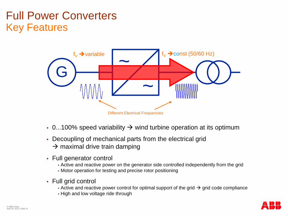
0...100% speed variability wind turbine operation at its optimum
Decoupling of mechanical parts from the electrical grid
maximal drive train damping
Full generator control Active and reactive power on the generator side controlled independently from the grid
Motor operation for testing and precise rotor positioning
Full grid control Active and reactive power control for optimal support of the grid grid code compliance
High and low voltage ride through
~G
~
Full Power Converters Key Features
fVvariable fVconst (50/60 Hz)
Different Electrical Frequencies

© ABB Group April 20, 2011 | Slide 11
MV and LV Converters ComparisonHigher Power Higher Current or Higher Voltage
Paralleled LV converters
690 V
...
~
G
~
~~
~G
~
3.3 kV
Single MV converter
There are two different converter concepts that can be applied in
order to reach higher power levels.
Low voltage converters are operated in parallel to handle the
current that increases when the power is higher.
MV converters runs on a higher voltage level. Thus the currents
are lower than in a system of the same power level operated at
lower voltages

© ABB Group April 20, 2011 | Slide 12
MV and LV Converters ComparisonHigher Power Higher Current or Higher Voltage
Paralleled LV converters
690 V
...
~
G
~
~~
~G
~3.3 kV
Single MV converter
LOWER VOLTAGE
HIGHER CURRENTS
Modules in parallel
More semiconductors
Availability by redundancy
HIGHER VOLTAGE
LOWER CURRENTS
One single converter handles up to
9 MVA
Less semiconductors
Availability by low parts count
As the power increases, MV is the
only practical solution

© ABB Group April 20, 2011 | Slide 13
MV and LV Converter ComparisonABB’s converter portfolio
ACS 800
PCS 6000
690 V
Paralleled for larger powers
Maximum of 6MW
BU LV Drives (Finland)
3.3 kV / 4.1 kV
Up to 9 MVA
BU MV Drives and Power Electronics
(Switzerland)
...
~
G
~
~~
~G
~

© ABB Group April 20, 2011 | Slide 14
ABB MV Converter Technology

© ABB Group April 20, 2011 | Slide 15
ABB MV Converter Technology Operating Principle
=
~ =
~G
fVvariable fVconst (50/60 Hz)
0 0.01 0.02 0.03 0.04 0.05 0.06 0.07 0.08 0.09 0.1-1
-0.8
-0.6
-0.4
-0.2
0
0.2
0.4
0.6
0.8
1
0 0.01 0.02 0.03 0.04 0.05 0.06 0.07 0.08 0.09 0.1-1
-0.8
-0.6
-0.4
-0.2
0
0.2
0.4
0.6
0.8
1
Wind Turbine Control
Torque Set Point
or
Power Set Point
Power Factor Set Point
or
Reactive Power Value (Q) Set Point
Different Electrical Frequencies

© ABB Group April 20, 2011 | Slide 16
ABB MV Converter Technology Voltage source inverter basics
=
~
Voltage
Source
InverterDC
Link
=
~
Voltage
Source
Inverter
Adjustable Parameters:
Frequency
Voltage level
Voltage phase shift

© ABB Group April 20, 2011 | Slide 17
ABB MV Converter Technology Main tasks
Active Power Control
The generator will be loaded with the
torque value set by the wind turbine
controller
Decoupling the generator from the grid:
Full control of the generator speed and
torque during normal and fault ride
through operation
Reactive Grid Power Control:
Grid stabilization
Operation at different power factors
Special Tasks:
Rotor Positioning mode
Back to Back test operation
=
~ =
~G
PGenerator
PResistor = PGenerator
PGrid = 0
=
~ =
~G
PGenerator
Different Electrical
Frequencies
PGrid = PGenerator
0 0.01 0.02 0.03 0.04 0.05 0.06 0.07 0.08 0.09 0.1-1
-0.8
-0.6
-0.4
-0.2
0
0.2
0.4
0.6
0.8
1
0 0.01 0.02 0.03 0.04 0.05 0.06 0.07 0.08 0.09 0.1-1
-0.8
-0.6
-0.4
-0.2
0
0.2
0.4
0.6
0.8
1
0 0.01 0.02 0.03 0.04 0.05 0.06 0.07 0.08 0.09 0.1-1
-0.8
-0.6
-0.4
-0.2
0
0.2
0.4
0.6
0.8
1
0 0.01 0.02 0.03 0.04 0.05 0.06 0.07 0.08 0.09 0.1-1
-0.8
-0.6
-0.4
-0.2
0
0.2
0.4
0.6
0.8
1
No Influence to the
Generator during Fault
Ride Through
Wind Turbine
Controller
Power or Torque
setpoint

© ABB Group April 20, 2011 | Slide 18
4 MVA 6 MVA 8 MVA5 MVA 7 MVA 9 MVA
3.3 kV
4 kV
SE
ABB MV Converter TechnologyPower Range of the PCS 6000 Wind
Higher powers by paralleling
of power modules

© ABB Group April 20, 2011 | Slide 19
LESS LOSSES
Lower currents and thus less losses (I2R) in
generator, converter, transformer and it’s
interconnections
EASY CABLING
Much smaller cabling, easy arrangement of
converter and transformer in tower foot
saving nacelle weight
ONLY 26 SEMICONDUCTORS
With MV technology, no paralleling of
components is required. This leads to reduced
parts count and thus higher reliability, less
complexity and less footprint.
PROVEN INDUSTRY STANDARD
MV converter technology is standard in industrial
applications of comparable power levels
G
~
~
ABB MV Converter TechnologyFeatures of the PCS 6000 Wind
PCS 6000
Weight Ratio
~1:4 PLosses = I2R
MV LV

© ABB Group April 20, 2011 | Slide 20
G
~
~
ABB MV Converter TechnologyOur System-Oriented Approach
The converter system has a strong influence on the whole drive train
Several drive train components depend on the power converter
Power converter acts as link between mechanical system and electrical grid
We provide a broad experience and deep system knowledge
ABB has dedicated specialists for grid code requirements and certification
Various simulation models are available - even customized models on request
Specifications for system relevant components such as transformer and main
circuit breaker are provided by ABB
Remote access
Different control methods available
Fuseless design
Simulation models
Hall testing / rotor positioning mode
Torque control
LVRT / HVRT
Overspeed protection
du/dt filter to protect generator
Designed for grid code compliance
Transformer spec by ABB
Transformer precharging
Inrush free grid connection
Breaker controlled by converter

© ABB Group April 20, 2011 | Slide 21
ABB MV Converter TechnologyThe Modular Concept at a Glance
The PCS 6000 modular converter family has a range from 3 to 9MVA with an
output voltage of 3.3kV or 4kV. The modular concept allows high flexibility for
customized converter solutions at the advantage of standardized high volume
production of the different modules.
The cooling unit, filters, circuit breakers and auxiliaries can be integrated in the
cabinets of the converter system and thus allow a very compact footprint.
PCS 6000 – Maximum Energy to the Grid
Grid side line
filter
PM
Gen
dv/dt filter Generator side converter Grid side converter
DC link with
voltage limiting
unitBreaker
Pre-charging Unit
Aux. Equipment
(heaters, fans, …) Cooling Unit
M
M
Converter
Control
Turbine Braking Resistor
AC 800 PEC S800 I/OVery Fast I/O
Win
d P
ark
Grid
Industrial PCFor converter commissioning, service,
maintenance and data logging

© ABB Group April 20, 2011 | Slide 22
PCS 6000 Wind
High Efficiency Converters for Renewable Energy
PM
Gen
dv/dt
filter Generator side converter Grid side converter
DC link with
voltage limiting
unitBreaker
Pre-charging Unit
Aux. Equipment
(heaters, fans, …) Cooling Unit
M
M
Converter Controller
Turbine Braking Resistor
AC 800 PEC S800 I/OVery Fast I/O
BreakerGrid side line
filter
ABB MV Converter TechnologyMain Components
Grid-side Converter
Generator-side
Converter
du/dt filter
Voltage limiting
unit (brake chopper)
Precharging unit

© ABB Group April 20, 2011 | Slide 23
PCS 6000 Wind
High Efficiency Converters for Renewable Energy
PM
Gen
dv/dt
filter Generator side converter Grid side converter
DC link with
voltage limiting
unitBreaker
Pre-charging Unit
Aux. Equipment
(heaters, fans, …) Cooling Unit
M
M
Converter Controller
Turbine Braking Resistor
AC 800 PEC S800 I/OVery Fast I/O
BreakerGrid side line
filter
ABB MV Converter TechnologyMain Components
Cooling unit
Circuit breakers
Grid side filter

© ABB Group April 20, 2011 | Slide 24
ABB MV Converter Technology PCS 6000 Family Modularization
High degree of standardization
High degree of flexibility
High degree of integration

© ABB Group April 20, 2011 | Slide 25
ABB MV Converter TechnologyReferences of the Technology Platform
ACS 6000 MV DriveFrequency converter to drive
an electrical motor
> 13’000 MVA delivered
=
~ =
~
Grid 1
U1
f1
Grid 2
U2
f2
PCS 6000 RailFrequency converter to connect
railway with regular grid
> 950 MVA delivered
PCS 6000 STATCOMFrequency converter for
reactive power control
> 200 MVA delivered
=
~ =
~M
=
~
PCS 6000 WindFrequency converter for
application in wind turbines
> 300 MVA delivered
=
~ =
~G

© ABB Group April 20, 2011 | Slide 26
ABB MV Converter TechnologyReferences of the PCS 6000 Wind
PCS 6000 Wind
=
~ =
~G
Alpha Ventus
First German offshore wind park
6 PCS 6000 successfully commissioned
in the Areva M5000 wind turbine
First offshore wind turbine applying MV
converter technology
5 MW permanent magnet generator
Series Production
New factory in Poland with annual
capacity of 200 units (+600)
Ongoing production of PCS 6000 for 5MW
offshore turbine
Prototypes
Factory in Switzerland with annual
capacity of 30 prototype units
Several prototype projects
Wind and tidal applications
Power range 1.1 to 6.5 MW

© ABB Group April 20, 2011 | Slide 27
PCS 6000 Wind Key ComponentsIGCT
The IGCT (Integrated Gate Commutated
Thyristor) is a switch, which can be turned on
and off by a fibre optic signal.
The IGCT is of a very robust design and has
the best balance between robustness,
efficiency, cost and reliability for medium
voltage converters.
The IGCT is explosion safe and optimal for
load cycling as faced in the wind industry.
Reverse conducting 6kV IGCT’s for the lower
power range (4kV AC) and asymmetric 4.5kV
IGCT’s for the higher power range (3.3kV AC)
are used
PCS 6000 – Maximum Energy to the Grid
Grid side line
filter
PM
Gen
dv/dt filter Generator side converter Grid side converter
DC link with
voltage limiting
unitBreaker
Pre-charging Unit
Aux. Equipment
(heaters, fans, …) Cooling Unit
M
M
Converter
Control
Turbine Braking Resistor
AC 800 PEC S800 I/OVery Fast I/O
Win
d P
ark
Grid
Industrial PCFor converter commissioning, service,
maintenance and data logging
MT

© ABB Group April 20, 2011 | Slide 28
PCS 6000 Wind Key ComponentsFrom IGCT to a 9MVA Converter
SE

© ABB Group April 20, 2011 | Slide 29
PCS 6000 Wind Key Components The control hardware
PCS 6000 – Maximum Energy to the Grid
Grid side line
filter
PM
Gen
dv/dt filter Generator side converter Grid side converter
DC link with
voltage limiting
unitBreaker
Pre-charging Unit
Aux. Equipment
(heaters, fans, …) Cooling Unit
M
M
Converter
Control
Turbine Braking Resistor
AC 800 PEC S800 I/OVery Fast I/O
Win
d P
ark
Grid
Industrial PCFor converter commissioning, service,
maintenance and data logging
Very Fast Applications
(VHDL)
Fast Applications
(MATLAB/Simulink)
Slow Appllications
(ABB Control Builder)
Cycle
Time
1 ms
100us
25ns
TASK LEVEL
low
speed
task
hig
h s
peed
task
Very Fast Applications
(VHDL)
Fast Applications
(MATLAB/Simulink)
Slow Appllications
(ABB Control Builder)
Cycle
Time
1 ms
100us
25ns
TASK LEVEL
low
speed
task
hig
h s
peed
task
The AC 800PEC (Power Electronic
Controller) is used as the main
controller. The 600MHz RISC 64-bit
processor allows complicated
control circuits
All the control equipment is running
on 24VDC and fiber optics.
MT

© ABB Group April 20, 2011 | Slide 30
PCS 6000 Wind Key ComponentsThe P3 Pfisterer© PLUG System
Pre-manufactured and tested cables with plug
No opening of cubicles during installation
100% water proof
MT

© ABB Group April 20, 2011 | Slide 31
PCS 6000 Wind Mechanical LayoutTypical Dimensions Converter Cabinet
3200 x 1200 x 2445
126” x 47” x 96”
(L x W x H / mm)
Approximately 5000 kg/11000lbs

© ABB Group April 20, 2011 | Slide 32
PCS 6000 Wind Mechanical LayoutTypical Dimensions Filter Cabinet / Braking Resistors
2200 x 1000 x 2445
86” x 39” x 96”
(L x W x H / mm)
Approximately 3200 kg/7000 lbs
1200 x 650 x 1025
47” x 25” x 40”
(L x W x H / mm)
Approximately 360 kg

Questions?
© ABB Group April 20, 2011 | Slide 33

© ABB Inc.April 20, 2011 | Slide 34
RemindersAutomation & Power World 2011
Please be sure to complete the workshop evaluation
Professional Development Hours (PDHs) and
Continuing Education Credits (CEUs):
You will receive a link via e-mail to print
certificates for all the workshops you have attended
during Automation & Power World 2011.
BE SURE YOU HAVE YOUR BADGE SCANNED
for each workshop you attend. If you do not have
your badge scanned you will not be able to obtain
PDHs or CEUs.

© ABB Group April 20, 2011 | Slide 35